EP3428006A1 - A child vehicle seat as well as an inlay for such a child vehicle seat - Google Patents
A child vehicle seat as well as an inlay for such a child vehicle seat Download PDFInfo
- Publication number
- EP3428006A1 EP3428006A1 EP18181835.2A EP18181835A EP3428006A1 EP 3428006 A1 EP3428006 A1 EP 3428006A1 EP 18181835 A EP18181835 A EP 18181835A EP 3428006 A1 EP3428006 A1 EP 3428006A1
- Authority
- EP
- European Patent Office
- Prior art keywords
- seat
- vehicle seat
- child
- child vehicle
- handle
- Prior art date
- Legal status (The legal status is an assumption and is not a legal conclusion. Google has not performed a legal analysis and makes no representation as to the accuracy of the status listed.)
- Granted
Links
Images






Classifications
-
- B—PERFORMING OPERATIONS; TRANSPORTING
- B60—VEHICLES IN GENERAL
- B60N—SEATS SPECIALLY ADAPTED FOR VEHICLES; VEHICLE PASSENGER ACCOMMODATION NOT OTHERWISE PROVIDED FOR
- B60N2/00—Seats specially adapted for vehicles; Arrangement or mounting of seats in vehicles
- B60N2/24—Seats specially adapted for vehicles; Arrangement or mounting of seats in vehicles for particular purposes or particular vehicles
- B60N2/26—Seats specially adapted for vehicles; Arrangement or mounting of seats in vehicles for particular purposes or particular vehicles for children
- B60N2/28—Seats readily mountable on, and dismountable from, existing seats or other parts of the vehicle
- B60N2/2803—Adaptations for seat belts
- B60N2/2812—Adaptations for seat belts for securing the child to the child seat
-
- B—PERFORMING OPERATIONS; TRANSPORTING
- B60—VEHICLES IN GENERAL
- B60N—SEATS SPECIALLY ADAPTED FOR VEHICLES; VEHICLE PASSENGER ACCOMMODATION NOT OTHERWISE PROVIDED FOR
- B60N2/00—Seats specially adapted for vehicles; Arrangement or mounting of seats in vehicles
- B60N2/24—Seats specially adapted for vehicles; Arrangement or mounting of seats in vehicles for particular purposes or particular vehicles
- B60N2/26—Seats specially adapted for vehicles; Arrangement or mounting of seats in vehicles for particular purposes or particular vehicles for children
- B60N2/28—Seats readily mountable on, and dismountable from, existing seats or other parts of the vehicle
- B60N2/2803—Adaptations for seat belts
- B60N2/2806—Adaptations for seat belts for securing the child seat to the vehicle
-
- B—PERFORMING OPERATIONS; TRANSPORTING
- B60—VEHICLES IN GENERAL
- B60N—SEATS SPECIALLY ADAPTED FOR VEHICLES; VEHICLE PASSENGER ACCOMMODATION NOT OTHERWISE PROVIDED FOR
- B60N2/00—Seats specially adapted for vehicles; Arrangement or mounting of seats in vehicles
- B60N2/24—Seats specially adapted for vehicles; Arrangement or mounting of seats in vehicles for particular purposes or particular vehicles
- B60N2/26—Seats specially adapted for vehicles; Arrangement or mounting of seats in vehicles for particular purposes or particular vehicles for children
- B60N2/28—Seats readily mountable on, and dismountable from, existing seats or other parts of the vehicle
- B60N2/2821—Seats readily mountable on, and dismountable from, existing seats or other parts of the vehicle having a seat and a base part
-
- B—PERFORMING OPERATIONS; TRANSPORTING
- B60—VEHICLES IN GENERAL
- B60N—SEATS SPECIALLY ADAPTED FOR VEHICLES; VEHICLE PASSENGER ACCOMMODATION NOT OTHERWISE PROVIDED FOR
- B60N2/00—Seats specially adapted for vehicles; Arrangement or mounting of seats in vehicles
- B60N2/24—Seats specially adapted for vehicles; Arrangement or mounting of seats in vehicles for particular purposes or particular vehicles
- B60N2/26—Seats specially adapted for vehicles; Arrangement or mounting of seats in vehicles for particular purposes or particular vehicles for children
- B60N2/28—Seats readily mountable on, and dismountable from, existing seats or other parts of the vehicle
- B60N2/2875—Seats readily mountable on, and dismountable from, existing seats or other parts of the vehicle inclinable, as a whole or partially
-
- B—PERFORMING OPERATIONS; TRANSPORTING
- B60—VEHICLES IN GENERAL
- B60N—SEATS SPECIALLY ADAPTED FOR VEHICLES; VEHICLE PASSENGER ACCOMMODATION NOT OTHERWISE PROVIDED FOR
- B60N2/00—Seats specially adapted for vehicles; Arrangement or mounting of seats in vehicles
- B60N2/24—Seats specially adapted for vehicles; Arrangement or mounting of seats in vehicles for particular purposes or particular vehicles
- B60N2/26—Seats specially adapted for vehicles; Arrangement or mounting of seats in vehicles for particular purposes or particular vehicles for children
- B60N2/28—Seats readily mountable on, and dismountable from, existing seats or other parts of the vehicle
- B60N2/2887—Fixation to a transversal anchorage bar, e.g. isofix
-
- B—PERFORMING OPERATIONS; TRANSPORTING
- B60—VEHICLES IN GENERAL
- B60N—SEATS SPECIALLY ADAPTED FOR VEHICLES; VEHICLE PASSENGER ACCOMMODATION NOT OTHERWISE PROVIDED FOR
- B60N2/00—Seats specially adapted for vehicles; Arrangement or mounting of seats in vehicles
- B60N2/90—Details or parts not otherwise provided for
- B60N2/919—Positioning and locking mechanisms
- B60N2002/952—Positioning and locking mechanisms characterised by details of the locking system
- B60N2002/957—Positioning and locking mechanisms characterised by details of the locking system the locking system prevents an abnormal or wrong mounting situation, i.e. deployment or functioning of a seat part being prevented if the seat or seat part is not properly mounted
Definitions
- the invention relates to a child vehicle seat comprising at least a base, a seat, a recline mechanism for moving the seat with respect to the base from at least a first position to a second position and vice versa, and a recline blocking mechanism for at least preventing displacement of the seat from the second position to the first position when a weight higher than a predetermined weight is exerted on the seat.
- the invention also relates to an inlay for such a child vehicle seat.
- Another disadvantage of this child vehicle seat is not suitable for younger or smaller children who can not yet be held in the seat by the three point safety belt of the vehicle but should be maintained in a child vehicle seat by an integrated harness in the child vehicle seat.
- At least one of the objects of the invention is to provide a child vehicle seat being also suitable for younger children, whereby reclining is also possible when the child is being maintained in the child vehicle seat by an integrated harness in the child vehicle seat.
- Another object of the invention is to provide a child vehicle seat whereby movement from the reclined position to an upright position as well as vice versa is prevented when a predetermined weight, like the weight of a child to use the child vehicle seat is exerted on the seat.
- the child vehicle seat also comprises a harness for holding a child and a deactivating mechanism for deactivating the recline blocking mechanism, which deactivating mechanism can be used when the harness is being used.
- the child vehicle seat is being used for relatively large children with a weight for example between 15-26 kilogram
- the child sitting in the seat is being held in the seat by means of the three point safety belt of the vehicle, a so called non-integral installation.
- the child vehicle seat can also be connected to the vehicle by means of the three point safety belt or a so called ISOFiX connectors together with an anti-rotation device (top-tether strap or support-leg).
- the recline blocking mechanism prevents at least displacement of the seat from the second position to the first position when a weight higher than a predetermined weight is exerted on the seat.
- the recline blocking mechanism prevents displacement of the seat from the second position to the first position as well as from the first position to the second position when a weight higher than a predetermined weight is exerted on the seat.
- the belts of the three point safety belt of the vehicle will not loosening around the child when the seat is being moved from the second to the first position and will also not be tightened around the child when the seat is being moved from the first to the second position.
- the weight exerted on the seat will be lower than the predetermined weight so that the recline mechanism can be operated. In use, this means that before the child sits down in the child vehicle seat, the parent has to decide in which position the seat of the child vehicle seat should be.
- the child vehicle seat In case that the child vehicle seat is being used for small children with a weight for example 9-18 kilogram, the child is being held in the seat by means of an integrated harness in the child vehicle seat, the so called integral installation.
- the child vehicle seat itself is being held in the vehicle by the three point safety belt of the vehicle or by means of so called ISOFiX system together with an anti-rotation device (top-tether strap or support-leg).
- the deactivating mechanism can now be used to deactivate the recline blocking mechanism so that the recline mechanism can be operated both with and without a child sitting in the child vehicle seat.
- An embodiment of the child vehicle seat according to the invention is characterized in that the child vehicle seat comprises a removable inlay for reducing the size of the seat, wherein the inlay comprises the deactivating mechanism for deactivating the recline blocking mechanism.
- the inlay will be used for the relatively small children with a weight for example between 9-18 kilogram.
- the recline blocking mechanism will be automatically be deactivated when installing the inlay in the seat.
- Another advantage is that the recline blocking mechanism van not be deactivated when there is no inlay in the seat
- the harness extend along or through the inlay.
- the recline mechanism comprises a handle being pivotable with respect to the seat from locking positions on the base defining the at least first and second positions of the seat, to an unlocked position wherein the seat is movable with respect to the base from at least a first position to a second position and vice versa
- the recline blocking mechanism comprises means to block pivoting of the handle, which means is movable from an unblocked position wherein the handle is pivotable with respect to the seat to a blocked position wherein pivoting of the handle is prevented.
- Another embodiment of the child vehicle seat according to the invention is characterized in that the means to block pivoting of the handle comprises an operating arm being pivotable against spring force from the unblocked position to the blocked position wherein the operating arm cooperates with the handle and prevent pivoting of the handle.
- Another embodiment of the child vehicle seat according to the invention is characterized in that the means to block pivoting of the handle comprises an extension provided on the handle, which extension is located in a passage in the operating arm in the blocked position thereof.
- the recline blocking mechanism comprises a pivotable plate provided in a seat portion of the seat, which plate cooperates with the operating arm, wherein the pivotable plate is in a rest position when the operating arm is in the unblocked position, whilst the plate is pivotable under a weight higher than the predermined weight on the seat if no deactivating mechanism is present in the seat to pivot the operating arm to the blocked position wherein the operating arm cooperates with the handle and blocks pivoting of the handle.
- Such a plate can simply be provided in the seat portion of the seat and will not provide discomfort for the child sitting on the seat portion.
- Another embodiment of the child vehicle seat according to the invention is characterized in that the means to block pivoting of the handle is maintained in the unblocked position by the deactivating mechanism of the inlay.
- the handle By holding the means to block pivoting of the handle in the unblocked position by the deactivating mechanism of the inlay, the handle can be moved between the several positions independent whether a child is sitting in the seat or not.
- Another embodiment of the child vehicle seat according to the invention is characterized in that the deactivating mechanism of the inlay comprises a strip being in abutment with the operating arm when the inlay is positioned in the seat, whereby the operating arm is maintained in the unblocked position.
- Such a strip simply prevents pivoting of the operating arm.
- Another embodiment of the child vehicle seat according to the invention is characterized in that the recline mechanism is movable to the unlocked position against spring force.
- the recline mechanism will normally be in its locked position and can only be moved to the unlocked position when the spring force has been overcome.
- Another embodiment of the child vehicle seat according to the invention is characterized in that the harness comprises at least a crotch belt, whilst the seat comprises a compartment for storing the crotch belt.
- the figures 1-6 show different views of a child vehicle seat 1 according to the invention.
- the child vehicle seat 1 comprises a base 2, a seat 3 and a removable inlay 4 for reducing the size of the seat 3.
- the base 2 can be provided on both sides with ISOFIX-connectors being slidable in and out the base 2 by means of knobs 5.
- the child vehicle seat 1 can be connected in a manner known per se to a vehicle.
- the seat 3 is provided with a seat portion 6, a backrest portion 7 and a movable headrest portion 8.
- the inlay 4 is provided with an inlay seat portion 9, an inlay backrest portion 10 and side portions 11 extending between the inlay seat portion 9 and inlay backrest portion 10.
- the inlay seat portion 9 rests on the seat portion 6 whilst the inlay backrest portion 10 rests against the backrest portion 7 of the seat 3. Due to the side portions 11 of the inlay 4 the width of the seat is reduced.
- a harness 12 is connected to the seat 3 and the inlay 4, which harness 12 comprises two shoulder belts 13, two side belts 14 and one crotch belt 15 being detachably connected to each other by means of a buckle 16.
- the belts of the harness 12 can be tensioned by means of strap 17.
- the child vehicle seat 1 described so far is known per se and will not be described in more detail.
- the child vehicle seat 1 comprises a pivotable plate 18 covering a compartment 19 in the seat portion 6.
- the crotch belt 15 and the buckle 16 can be stored in the compartment 19. This will be done when the child vehicle seat will be used as a non-integral seat for children with a weight for example 15-36 kilogram, whereby the child vehicle seat 1 is being used without inlay 4 and without the two shoulder belts 13 and the two side belts 14.
- FIG 5A shows the inlay 4 according to the invention.
- the inlay 4 differs from the inlays known so far in that the inlay 4 is provided with a deactivating mechanism comprising a strip 20 located partly inside the inlay seat portion 9 and extending partly below the inlay seat portion 9. At an end remote of the inlay seat portion 9, the strip 20 is provided with an end part 21.
- the strip 20 in located inside a crotch part 120 of the inlay 4.
- Figures 7A-7C are cross sections of the child seat as shown in figure 2 showing respectively the seat 3 in a first locked position and a first unlocked position without a child and a first locked position with a child sitting in the seat 3.
- the base 2 is provided with a first curved slot 38 wherein a pen 22 connected to the seat 3 is slidable movable.
- a spring 23 is connected to the pen 22 of the seat 3. At an end remote of pen 22 the spring 23 is connected to an extension 24 on the base 2.
- the base 2 is provided with a second slot 25 having a main longitudinal slot 26 and three position slots 27, 28, 29 extending perpendicular to the main longitudinal slot 26.
- a pen 30 connected to the seat 3 is slidable movable.
- the seat 3 is provided with a lever-shaped handle 31 being pivotable about an axis 32. Between a first end 33 of the handle 31 and a front side of the seat 3 a spring 34 is located. At a second end remote of the first end the handle 31 is provided with a pen 35 being slidable movable in second slot 25. In the position as shown in figure 7A the pen 35 is located in the first position slot 27, whereby the seat 3 is located in a first upright position. In the first position, the pens 22 and 30 are located near lower ends of the slots 38, 26.
- the seat 3 comprises a recline mechanism comprising amongst others the slots 25, 38 in the base 2, the springs 23 and 34, the pens 22, 30, 35 of the seat 3 and the handle 31.
- the recline mechanism works as follows.
- a user will move the first end 33 of the handle 31 against spring force of spring 34 so that the handle 31 will be pivoted about axis 32 in the direction as indicated by arrow Pi.
- the pen 35 will be moved in the direction as indicated by arrow P2 from the first position slot 27 into the main longitudinal slot 26.
- the pen 35 together with pen 30 can be moved under spring force of spring 23 in the main longitudinal slot 26 in the direction as indicated by arrow P3 until the pen 35 is located near the second or third position slot 28, 29.
- the seat will be in an intermediate position whilst in the third position the seat will be in a reclined position.
- the pen 22 of the seat 3 is moved under spring force of spring 23 in a direction indicated by arrow P4.
- the handle 31 By releasing the handle 31, the handle 31 will be moved under the spring force of springs 23, 34 to a position wherein the pen 35 will be moved into the nearest position slot 27, 28, 29, being the first slot when moving the pen 35 in the direction indicated by arrow P3.
- the handle 31 is also provided with an extension 36 directed upwards and towards the front side of the seat 3.
- the extension 36 is provided with a locking element 37.
- the seat 3 is furthermore provided with a lever-shaped operating arm 41 being pivotable about an axis 42.
- the operating arm 41 comprises with a first part 43 directed towards the handle 31 and a second part 44 directed towards the plate 18.
- the plate 18 is pivotable about axis 45.
- the first part 43 is provided with a passage 143 as can be seen in figure 7D .
- the second part 44 is L-shaped. Its end 47 is in abutment with a lower side of the plate 18.
- a spring 46 is connected to the operating arm 41 biasing the operating arm 41 into an unblocked position as shown in figure 7A , in which unblocked position the locking element 37 of the extension 36 of the handle 31 is not located inside the passage of the operating arm 41.
- the seat 3 comprises a recline blocking mechanism comprising amongst others the extension 36 on the handle 31, the operating arm 41, the spring 46 and the plate 18.
- the figures 7A-7C show the child vehicle seat 1 without inlay 4, whereby the child vehicle seat will be used for relative large children with a weight for example between 15-36 kilogram. With such a seat the child will be held inside the seat 3 by means of the three point safety belt of the vehicle.
- a child 50 is now sitting in the seat 3, whereby his upper legs 51 rest against the seat portion 6 of the seat 3. Since the weight of the child 50 is larger than a predetermined weight of for example one kilogram, the plate 18 will be pivoted about axis 45 in a direction indicated by arrow P5, whereby the plate 18 will exert a force onto the end 47 of the L-shaped second part 44. Due to said force, the operating arm 41 will be pivoted against spring force of spring 46 in a counter clockwise direction as indicated by arrow P6, whereby the passage in the first part 43 of the operating arm 41 will be moved over the locking element 37 of the extension 36 of the handle to the blocking position of the operating arm 41.
- the handle 31 In the blocking position of the operating arm 41, the handle 31 can no longer be moved to the position as shown in figure 7B , so that it is no longer possible to change the position of the seat 3 with respect to the base 2. In the blocking position the seat 3 can neither be moved from the first upright position to the second or third position nor from the third reclined position to the second or first position.
- the operating arm 41 will be pivoted under spring force of spring 46 in a clockwise direction opposite to arrow P6, whereby the passage in the first part 43 of the operating arm 41 will be moved away from the locking element 37 of the extension 36 of the handle to the unblocking position of the operating arm 41. Furthermore, the L-shaped second part 44 will force the plate 18 to pivot about axis 45 in a direction opposite to arrow P5 to the situation as shown in figure 7A .
- Figures 8A-8C are cross sections of the child seat as shown in figure 2 showing respectively the seat 3 in a third locked position and a third unlocked position without a child and a third locked position with a child sitting in the seat 3.
- the figures 9A-9B are cross sections of the child seat as shown in figure 1 showing respectively the seat in a first locked position without and with a child sitting in the seat.
- the figures 9A-9B show the child vehicle seat 1 with the inlay 4, whereby the child vehicle seat will be used as an integral seat for relative small children with a weight for example between 9-18 kilogram. With such a seat the child will be held inside the inlay 4 and the seat 3 by means of the harness 12.
- the end part 21 of the strip 20 will be inserted in an opening 55 in front of the plate 18 until the end part 21 abuts against the inner corner 56 of the L-shaped second part 44.
- the operating arm 41 being in its unblocked position is now locked against movement towards the blocked position.
- the deactivating mechanism comprising the strip 20 and the L-shaped second part 44 of the lever-shaped operating arm 41 is now activated and the recline blocking mechanism is deactivated.
- Figures 10A-10B are cross sections of the child seat as shown in figure 1 showing respectively the seat in a first unlocked position without and with a child sitting in the seat.
- FIGS iiA and 11B are perspective views of a second embodiment of a deactivating mechanism 61 according to the invention.
- the deactivating mechanism 61 comprises the L-shaped second parts 44 of the lever-shaped operating arm 41.
- the L-shaped second parts 44 extend through passages 62 in a wall 63 of the compartment 19.
- the deactivating mechanism 61 also comprises a strip 64 being provided with a handle 65.
- the handle 65 is slidable along a slot 66 in the wall 63 in and opposite a direction indicated by arrow P7 to move the strip 64 from a rest position to a deactivating position.
- the L-shaped second parts 44 In the rest position ( figure 11A ) the L-shaped second parts 44 can freely be moved through the passages 62 in the wall 63 of the compartment 19 so that the lever-shaped operating arm 41 can be pivoted. In the deactivating position ( figure 11B ) the L-shaped second parts 44 can no longer be moved through the passages 62 in the wall 63 of the compartment 19 thereby blocking the pivotal movement of the lever-shaped operating arm 41.
- Figure 12 is a perspective view of a third embodiment of a deactivating mechanism 71 according to the invention.
- the strip 20 is connected to the crotch belt 15 by means of straps 72.
- the end part 21 of the strip 20 is in engagement with the L-shaped second parts 44 of the lever-shaped operating arm 41 so that the pivotal movement of the lever-shaped operating arm 41 is blocked.
- the buckle 16 can be used to connect the child to the seat 3.
- the end part 21 of the strip 20 is removed out of engagement with the L-shaped second parts 44 of the lever-shaped operating arm 41 so that the lever-shaped operating arm 41 can be pivoted again.
Landscapes
- Engineering & Computer Science (AREA)
- Health & Medical Sciences (AREA)
- Child & Adolescent Psychology (AREA)
- General Health & Medical Sciences (AREA)
- Aviation & Aerospace Engineering (AREA)
- Transportation (AREA)
- Mechanical Engineering (AREA)
- Seats For Vehicles (AREA)
Abstract
Description
- The invention relates to a child vehicle seat comprising at least a base, a seat, a recline mechanism for moving the seat with respect to the base from at least a first position to a second position and vice versa, and a recline blocking mechanism for at least preventing displacement of the seat from the second position to the first position when a weight higher than a predetermined weight is exerted on the seat.
- The invention also relates to an inlay for such a child vehicle seat.
- By a child vehicle seat of
EP1839936B1 , the child is being held in the seat using a three point safety belt of the vehicle. - When bringing the child safety seat between the various positions, a problem arises when seat is displaced from the reclined position to the upright position of the child safety seat. When the three point safety belt of the vehicle is secured around the child as the child vehicle seat is placed in a reclined position, a greater length of seat belt of the vehicle has to be used than if the child safety seat is placed in an upright position. The retractor arrangement of the three point safety belt is not capable of reducing the belt length when moving the child vehicle seat from the reclined position to an upright position. This shifting of positions thereby results in a loose fastening of the belt around the child. This loose arrangement of the belt is not satisfactory when regarding the safety requirements of a child safety seat. If the adult does not retention or tighten up the three point safety belt, the child has a higher risk of injury in case of a sudden retardation of the vehicle.
- By a child vehicle seat is known from
EP1839936B1 movement from a reclined position to an upright position is prevented when a predetermined weight, like the weight of a child to use the child vehicle seat is exerted on the seat. However movement from the upright position to the reclined position is still possible. - Another disadvantage of this child vehicle seat is not suitable for younger or smaller children who can not yet be held in the seat by the three point safety belt of the vehicle but should be maintained in a child vehicle seat by an integrated harness in the child vehicle seat.
- At least one of the objects of the invention is to provide a child vehicle seat being also suitable for younger children, whereby reclining is also possible when the child is being maintained in the child vehicle seat by an integrated harness in the child vehicle seat.
- Another object of the invention is to provide a child vehicle seat whereby movement from the reclined position to an upright position as well as vice versa is prevented when a predetermined weight, like the weight of a child to use the child vehicle seat is exerted on the seat.
- One object is accomplished with the child vehicle seat according to the invention in that the child vehicle seat also comprises a harness for holding a child and a deactivating mechanism for deactivating the recline blocking mechanism, which deactivating mechanism can be used when the harness is being used.
- In case that the child vehicle seat is being used for relatively large children with a weight for example between 15-26 kilogram, the child sitting in the seat is being held in the seat by means of the three point safety belt of the vehicle, a so called non-integral installation. The child vehicle seat can also be connected to the vehicle by means of the three point safety belt or a so called ISOFiX connectors together with an anti-rotation device (top-tether strap or support-leg). The recline blocking mechanism prevents at least displacement of the seat from the second position to the first position when a weight higher than a predetermined weight is exerted on the seat. Preferably, the recline blocking mechanism prevents displacement of the seat from the second position to the first position as well as from the first position to the second position when a weight higher than a predetermined weight is exerted on the seat.
- In this manner the belts of the three point safety belt of the vehicle will not loosening around the child when the seat is being moved from the second to the first position and will also not be tightened around the child when the seat is being moved from the first to the second position.
- When no child is sitting in the child vehicle seat the weight exerted on the seat will be lower than the predetermined weight so that the recline mechanism can be operated. In use, this means that before the child sits down in the child vehicle seat, the parent has to decide in which position the seat of the child vehicle seat should be.
- In case that the child vehicle seat is being used for small children with a weight for example 9-18 kilogram, the child is being held in the seat by means of an integrated harness in the child vehicle seat, the so called integral installation. The child vehicle seat itself is being held in the vehicle by the three point safety belt of the vehicle or by means of so called ISOFiX system together with an anti-rotation device (top-tether strap or support-leg).
- . Since the child is not being held in the child vehicle seat by the three point safety belt of the vehicle but by the harness, there is no risk that the belts around the child will be loosening or tightened when the child vehicle seat is being moved from a first, for example upright position to a second, for example reclined position. The deactivating mechanism can now be used to deactivate the recline blocking mechanism so that the recline mechanism can be operated both with and without a child sitting in the child vehicle seat.
- An embodiment of the child vehicle seat according to the invention is characterized in that the child vehicle seat comprises a removable inlay for reducing the size of the seat, wherein the inlay comprises the deactivating mechanism for deactivating the recline blocking mechanism.
- The inlay will be used for the relatively small children with a weight for example between 9-18 kilogram. By providing the inlay with the deactivating mechanism, the recline blocking mechanism will be automatically be deactivated when installing the inlay in the seat. Another advantage is that the recline blocking mechanism van not be deactivated when there is no inlay in the seat The harness extend along or through the inlay.
- Another embodiment of the child vehicle seat according to the invention is characterized in that the recline mechanism comprises a handle being pivotable with respect to the seat from locking positions on the base defining the at least first and second positions of the seat, to an unlocked position wherein the seat is movable with respect to the base from at least a first position to a second position and vice versa, whilst the recline blocking mechanism comprises means to block pivoting of the handle, which means is movable from an unblocked position wherein the handle is pivotable with respect to the seat to a blocked position wherein pivoting of the handle is prevented.
- With such a handle the displacement of the seat between a first and a second position and if desired other positions is relatively easy. By preventing the handle to pivot, blocking of the recline mechanism is also relatively easy.
- Another embodiment of the child vehicle seat according to the invention is characterized in that the means to block pivoting of the handle comprises an operating arm being pivotable against spring force from the unblocked position to the blocked position wherein the operating arm cooperates with the handle and prevent pivoting of the handle.
- When no force is exerted on the operating arm, spring force will keep the operating arm in the unblocked position wherein the handle can be operated. In case that the operating arm is being pivoted against spring force from the unblocked position to the blocked position, the handle can no longer be pivoted and the seat can no longer be displaced from its position to the one of the other positions.
- Another embodiment of the child vehicle seat according to the invention is characterized in that the means to block pivoting of the handle comprises an extension provided on the handle, which extension is located in a passage in the operating arm in the blocked position thereof.
- When the extension of the handle is located in the passage of the operating arm, pivoting of the handle is no longer possible and the seat can no longer be displaced from its position to the one of the other positions.
- Another embodiment of the child vehicle seat according to the invention is characterized in that the recline blocking mechanism comprises a pivotable plate provided in a seat portion of the seat, which plate cooperates with the operating arm, wherein the pivotable plate is in a rest position when the operating arm is in the unblocked position, whilst the plate is pivotable under a weight higher than the predermined weight on the seat if no deactivating mechanism is present in the seat to pivot the operating arm to the blocked position wherein the operating arm cooperates with the handle and blocks pivoting of the handle.
- Such a plate can simply be provided in the seat portion of the seat and will not provide discomfort for the child sitting on the seat portion.
- Another embodiment of the child vehicle seat according to the invention is characterized in that the means to block pivoting of the handle is maintained in the unblocked position by the deactivating mechanism of the inlay.
- By holding the means to block pivoting of the handle in the unblocked position by the deactivating mechanism of the inlay, the handle can be moved between the several positions independent whether a child is sitting in the seat or not.
- Another embodiment of the child vehicle seat according to the invention is characterized in that the deactivating mechanism of the inlay comprises a strip being in abutment with the operating arm when the inlay is positioned in the seat, whereby the operating arm is maintained in the unblocked position.
- Such a strip simply prevents pivoting of the operating arm.
- Another embodiment of the child vehicle seat according to the invention is characterized in that the recline mechanism is movable to the unlocked position against spring force.
- In this manner, the recline mechanism will normally be in its locked position and can only be moved to the unlocked position when the spring force has been overcome.
- Another embodiment of the child vehicle seat according to the invention is characterized in that the harness comprises at least a crotch belt, whilst the seat comprises a compartment for storing the crotch belt.
- The child vehicle seat according to the invention will further be explained with reference to the drawings, wherein,
-
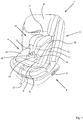
figure 1 is a perspective view of a child vehicle seat according to the invention with an inlay, -
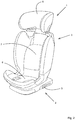
figure 2 is a perspective view of the child vehicle seat as shown infigure 1 without an inlay, -
figure 3 is a perspective view of the child vehicle seat as shown infigure 2 without covers, -
figure 4 is a perspective view of a part of the child vehicle seat as shown infigure 2 , -
figure 5A and5B are a perspective view of the inlay of the child vehicle seat as shown infigure 1 and a a perspective view of a detailed part of the inlay, -
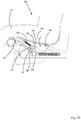
figure 6 is a perspective view of a part of the child vehicle seat as shown infigure 1 , -
figures 7A-7D are cross sections of the child seat as shown infigure 2 showing respectively the seat in a first locked position and a first unlocked position without a child and a first locked position with a child sitting in the seat and a a perspective view of a detailed part of the recline blocking mechanism, -
figures 8A-8C are cross sections of the child seat as shown infigure 2 showing respectively the seat in a third locked position and a third unlocked position without a child and a third locked position with a child sitting in the seat, -
figures 9A-9B are cross sections of the child seat as shown infigure 1 showing respectively the seat in a first locked position without and with a child sitting in the seat, with a first embodiment of the deactivating mechanism according to the invention, -
figures 10A-10B are cross sections of the child seat as shown infigure 1 showing respectively the seat in a first unlocked position without and with a child sitting in the seat, -
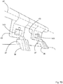
figures 11A and11B are perspective views of a second embodiment of a deactivating mechanism according to the invention, in a rest position and deactivating position respectively -
figure 12 is a perspective view of a third embodiment of a deactivating mechanism according to the invention. - In the drawings, like reference numerals refer to like elements.
- The
figures 1-6 show different views of achild vehicle seat 1 according to the invention. Thechild vehicle seat 1 comprises abase 2, aseat 3 and aremovable inlay 4 for reducing the size of theseat 3. - The
base 2 can be provided on both sides with ISOFIX-connectors being slidable in and out thebase 2 by means ofknobs 5. By means of the ISOFIX-connectors thechild vehicle seat 1 can be connected in a manner known per se to a vehicle. - The
seat 3 is provided with aseat portion 6, abackrest portion 7 and amovable headrest portion 8. - The
inlay 4 is provided with aninlay seat portion 9, aninlay backrest portion 10 andside portions 11 extending between theinlay seat portion 9 andinlay backrest portion 10. As can be seen infigure 1 , theinlay seat portion 9 rests on theseat portion 6 whilst theinlay backrest portion 10 rests against thebackrest portion 7 of theseat 3. Due to theside portions 11 of theinlay 4 the width of the seat is reduced. When using theinlay 4, aharness 12 is connected to theseat 3 and theinlay 4, which harness 12 comprises twoshoulder belts 13, twoside belts 14 and onecrotch belt 15 being detachably connected to each other by means of abuckle 16. The belts of theharness 12 can be tensioned by means ofstrap 17. - The
child vehicle seat 1 described so far is known per se and will not be described in more detail. - As can be seen in
figures 3 and4 thechild vehicle seat 1 comprises apivotable plate 18 covering acompartment 19 in theseat portion 6. Thecrotch belt 15 and thebuckle 16 can be stored in thecompartment 19. This will be done when the child vehicle seat will be used as a non-integral seat for children with a weight for example 15-36 kilogram, whereby thechild vehicle seat 1 is being used withoutinlay 4 and without the twoshoulder belts 13 and the twoside belts 14. -
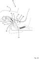
Figure 5A shows theinlay 4 according to the invention. Theinlay 4 differs from the inlays known so far in that theinlay 4 is provided with a deactivating mechanism comprising astrip 20 located partly inside theinlay seat portion 9 and extending partly below theinlay seat portion 9. At an end remote of theinlay seat portion 9, thestrip 20 is provided with anend part 21. As can be best seen infigure 5B thestrip 20 in located inside acrotch part 120 of theinlay 4. -
Figures 7A-7C are cross sections of the child seat as shown infigure 2 showing respectively theseat 3 in a first locked position and a first unlocked position without a child and a first locked position with a child sitting in theseat 3. - The
base 2 is provided with a firstcurved slot 38 wherein apen 22 connected to theseat 3 is slidable movable. Aspring 23 is connected to thepen 22 of theseat 3. At an end remote ofpen 22 thespring 23 is connected to anextension 24 on thebase 2. - The
base 2 is provided with asecond slot 25 having a mainlongitudinal slot 26 and threeposition slots longitudinal slot 26. In said main longitudinal slot 26 apen 30 connected to theseat 3 is slidable movable. Theseat 3 is provided with a lever-shapedhandle 31 being pivotable about anaxis 32. Between afirst end 33 of thehandle 31 and a front side of the seat 3 aspring 34 is located. At a second end remote of the first end thehandle 31 is provided with apen 35 being slidable movable insecond slot 25. In the position as shown infigure 7A thepen 35 is located in thefirst position slot 27, whereby theseat 3 is located in a first upright position. In the first position, thepens slots - The
seat 3 comprises a recline mechanism comprising amongst others theslots base 2, thesprings pens seat 3 and thehandle 31. - The recline mechanism works as follows.
- To move the
seat 3 from a first position to a second or third position, a user will move thefirst end 33 of thehandle 31 against spring force ofspring 34 so that thehandle 31 will be pivoted aboutaxis 32 in the direction as indicated by arrow Pi. By doing so, thepen 35 will be moved in the direction as indicated by arrow P2 from thefirst position slot 27 into the mainlongitudinal slot 26. As soon as thepen 35 is located in the mainlongitudinal slot 26, thepen 35 together withpen 30 can be moved under spring force ofspring 23 in the mainlongitudinal slot 26 in the direction as indicated by arrow P3 until thepen 35 is located near the second orthird position slot pen 22 of theseat 3 is moved under spring force ofspring 23 in a direction indicated by arrow P4. - By releasing the
handle 31, thehandle 31 will be moved under the spring force ofsprings pen 35 will be moved into thenearest position slot pen 35 in the direction indicated by arrow P3. - At the second end the
handle 31 is also provided with anextension 36 directed upwards and towards the front side of theseat 3. At an end remote of thepen 35 theextension 36 is provided with a lockingelement 37. - The
seat 3 is furthermore provided with a lever-shapedoperating arm 41 being pivotable about anaxis 42. Theoperating arm 41 comprises with afirst part 43 directed towards thehandle 31 and asecond part 44 directed towards theplate 18. As can be seen infigures 7A-7C theplate 18 is pivotable aboutaxis 45. Thefirst part 43 is provided with apassage 143 as can be seen infigure 7D . - The
second part 44 is L-shaped. Itsend 47 is in abutment with a lower side of theplate 18. - A
spring 46 is connected to theoperating arm 41 biasing theoperating arm 41 into an unblocked position as shown infigure 7A , in which unblocked position the lockingelement 37 of theextension 36 of thehandle 31 is not located inside the passage of theoperating arm 41. - The
seat 3 comprises a recline blocking mechanism comprising amongst others theextension 36 on thehandle 31, theoperating arm 41, thespring 46 and theplate 18. - The
figures 7A-7C show thechild vehicle seat 1 withoutinlay 4, whereby the child vehicle seat will be used for relative large children with a weight for example between 15-36 kilogram. With such a seat the child will be held inside theseat 3 by means of the three point safety belt of the vehicle. - In the
figures 7A and7B situations are shown whereby no child is present in theseat 3. In these situations, the recline mechanism can be operated as described above. - As can be seen in
figure 7C , achild 50 is now sitting in theseat 3, whereby hisupper legs 51 rest against theseat portion 6 of theseat 3. Since the weight of thechild 50 is larger than a predetermined weight of for example one kilogram, theplate 18 will be pivoted aboutaxis 45 in a direction indicated by arrow P5, whereby theplate 18 will exert a force onto theend 47 of the L-shapedsecond part 44. Due to said force, theoperating arm 41 will be pivoted against spring force ofspring 46 in a counter clockwise direction as indicated by arrow P6, whereby the passage in thefirst part 43 of theoperating arm 41 will be moved over the lockingelement 37 of theextension 36 of the handle to the blocking position of theoperating arm 41. In the blocking position of theoperating arm 41, thehandle 31 can no longer be moved to the position as shown infigure 7B , so that it is no longer possible to change the position of theseat 3 with respect to thebase 2. In the blocking position theseat 3 can neither be moved from the first upright position to the second or third position nor from the third reclined position to the second or first position. - As soon as the child leaves the
seat 3, theoperating arm 41 will be pivoted under spring force ofspring 46 in a clockwise direction opposite to arrow P6, whereby the passage in thefirst part 43 of theoperating arm 41 will be moved away from the lockingelement 37 of theextension 36 of the handle to the unblocking position of theoperating arm 41. Furthermore, the L-shapedsecond part 44 will force theplate 18 to pivot aboutaxis 45 in a direction opposite to arrow P5 to the situation as shown infigure 7A . -
Figures 8A-8C are cross sections of the child seat as shown infigure 2 showing respectively theseat 3 in a third locked position and a third unlocked position without a child and a third locked position with a child sitting in theseat 3. - The only difference between the
figures 7A-7C and thefigures 8A-8C is that in thefigures 7A-7C the seat is in the first upright position, whilst in thefigures 8A-8C theseat 3 is in the third reclined position. In the third position, thepens slots - The
figures 9A-9B are cross sections of the child seat as shown infigure 1 showing respectively the seat in a first locked position without and with a child sitting in the seat. Thefigures 9A-9B show thechild vehicle seat 1 with theinlay 4, whereby the child vehicle seat will be used as an integral seat for relative small children with a weight for example between 9-18 kilogram. With such a seat the child will be held inside theinlay 4 and theseat 3 by means of theharness 12. - By positioning the
inlay 4 onto theseat portion 6 of theseat 3, theend part 21 of thestrip 20 will be inserted in anopening 55 in front of theplate 18 until theend part 21 abuts against theinner corner 56 of the L-shapedsecond part 44. - The
operating arm 41 being in its unblocked position is now locked against movement towards the blocked position. - As can be seen in
figure 9B , although achild 50 is sitting on theseat portion 6 of theseat 3, theplate 18 is prevented by moving in the direction as indicated by arrow P5 (seefigures 6 ,7C ) by theend 47 of the L-shapedsecond part 44. - The deactivating mechanism comprising the
strip 20 and the L-shapedsecond part 44 of the lever-shapedoperating arm 41 is now activated and the recline blocking mechanism is deactivated. -
Figures 10A-10B are cross sections of the child seat as shown infigure 1 showing respectively the seat in a first unlocked position without and with a child sitting in the seat. - The only difference between the
figures 9A-9B and thefigures 10A-10B is that in thefigures 9A-9B the recline mechanism is in its locked position in thefigures 10A-10B the recline mechanism is in its unlocked position so that theseat 3 can be moved from the first to the second or third position and vice versa. - Figures iiA and 11B are perspective views of a second embodiment of a
deactivating mechanism 61 according to the invention. Thedeactivating mechanism 61 comprises the L-shapedsecond parts 44 of the lever-shapedoperating arm 41. The L-shapedsecond parts 44 extend throughpassages 62 in awall 63 of thecompartment 19. Thedeactivating mechanism 61 also comprises astrip 64 being provided with ahandle 65. Thehandle 65 is slidable along aslot 66 in thewall 63 in and opposite a direction indicated by arrow P7 to move thestrip 64 from a rest position to a deactivating position. In the rest position (figure 11A ) the L-shapedsecond parts 44 can freely be moved through thepassages 62 in thewall 63 of thecompartment 19 so that the lever-shapedoperating arm 41 can be pivoted. In the deactivating position (figure 11B ) the L-shapedsecond parts 44 can no longer be moved through thepassages 62 in thewall 63 of thecompartment 19 thereby blocking the pivotal movement of the lever-shapedoperating arm 41. -
Figure 12 is a perspective view of a third embodiment of adeactivating mechanism 71 according to the invention. - By this embodiment the
strip 20 is connected to thecrotch belt 15 by means ofstraps 72. In the position as shown infigure 12 theend part 21 of thestrip 20 is in engagement with the L-shapedsecond parts 44 of the lever-shapedoperating arm 41 so that the pivotal movement of the lever-shapedoperating arm 41 is blocked. Thebuckle 16 can be used to connect the child to theseat 3. By storing thebuckle 16 in thecompartment 19, theend part 21 of thestrip 20 is removed out of engagement with the L-shapedsecond parts 44 of the lever-shapedoperating arm 41 so that the lever-shapedoperating arm 41 can be pivoted again. - It is also possible to block the
operating arm 41 in its unlocked position by other means. -
- 1
- child vehicle seat
- 2
- base
- 3
- seat
- 4
- inlay
- 5
- knob
- 6
- seat portion
- 7
- backrest portion
- 8
- headrest portion
- 9
- inlay seat portion
- 10
- inlay backrest portion
- 11
- side portion
- 12
- harness
- 13
- shoulder belt
- 14
- side belt
- 15
- crotch belt
- 16
- buckle
- 17
- strap
- 18
- plate
- 19
- compartment
- 20
- strip
- 21
- part
- 22
- pen
- 23
- spring
- 24
- extension
- 25
- second slot
- 26
- longitudinal slot
- 27
- position slot
- 28
- position slot
- 29
- position slot
- 30
- pen
- 31
- lever-shaped handle
- 32
- axis
- 33
- first end
- 34
- spring
- 35
- pen
- 36
- extension
- 37
- locking element
- 38
- slot
- 41
- lever-shaped operating arm
- 42
- axis
- 43
- first part
- 44
- second part
- 45
- axis
- 46
- spring
- 47
- end
- 50
- child
- 51
- leg
- 55
- opening
- 56
- inner corner
- 61
- deactivating mechanism
- 62
- passage
- 63
- wall
- 64
- strip
- 65
- handle
- 66
- slot
- 71
- deactivating mechanism
- 72
- strap
- 120
- crotch part
- 143
- passage
- P1
- arrow
- P2
- arrow
- P3
- arrow
- P4
- arrow
- P5
- arrow
- P6
- arrow
- P7
- arrow
Claims (11)
- A child vehicle seat (i) comprising at least a base (2), a seat (3), a recline mechanism for moving the seat (3) with respect to the base (2) from at least a first position to a second position and vice versa, and a recline blocking mechanism for at least preventing displacement of the seat (3) from the second position to the first position when a weight higher than a predetermined weight is exerted on the seat (3), characterized in that the child vehicle seat (1) also comprises a harness (12) for holding a child (50) in the seat (3) and a deactivating mechanism for deactivating the recline blocking mechanism, which deactivating mechanism can be used when the harness is being used.
- A child vehicle seat (1) according to claim 1, characterized in that the child vehicle seat (1) comprises a removable inlay (4) for reducing the size of the seat (3), which inlay 4 comprises the deactivating mechanism for deactivating the recline blocking mechanism.
- A child vehicle seat (1) according to claim 1 or 2, characterized in that the recline mechanism comprises a handle (31) being pivotable with respect to the seat (3) from locking positions on the base (2) defining the at least first and second positions of the seat (3), to an unlocked position wherein the seat (3) is movable with respect to the base (2) from at least the first position to the second position and vice versa, whilst the recline blocking mechanism comprises means to block pivoting of the handle (31), which means is movable from an unblocked position wherein the handle (31) is pivotable with respect to the seat (3) to a blocked position wherein pivoting of the handle (31) is prevented.
- A child vehicle seat (1) according to claim 3, characterized in that the means to block pivoting of the handle (31) comprises an operating arm (41) being pivotable against spring force from the unblocked position to the blocked position wherein the operating arm (41) cooperates with the handle (31) and prevent pivoting of the handle (31).
- A child vehicle seat (1) according to claim 4, characterized in that the means to block pivoting of the handle (31) comprises an extension (36) provided on the handle (31), which extension (36) is located in a passage in the operating arm (41) in the blocked position thereof.
- A child vehicle seat (1) according to claim 4 or 5, characterized in that the recline blocking mechanism comprises a pivotable plate (18) provided in a seat portion (6) of the seat (3), which plate cooperates with the operating arm (41), wherein the pivotable plate is in a rest position when the operating arm (41) is in the unblocked position, whilst the plate is pivotable under a weight higher than the predermined weight on the seat (3) if no deactivating mechanism is present in the seat (3) to pivot the operating arm (41) to the blocked position wherein the operating arm (41) cooperates with the handle (31) and blocks pivoting of the handle (31).
- A child vehicle seat (1) according to one of the preceding claims 3-6, characterized in that the means to block pivoting of the handle (31) is maintained in the unblocked position by the deactivating mechanism of the inlay (4).
- A child vehicle seat (1) according to claim 4, 5 or 6, characterized in that the deactivating mechanism comprises a strip (20) being in abutment with the operating arm (41), whereby the operating arm (41) is maintained in the unblocked position.
- A child vehicle seat (1) to one of the preceding claims, characterized in that the recline mechanism is movable to the unlocked position against spring force.
- A child vehicle seat (i) to one of the preceding claims, characterized in that the harness (12) comprises at least a crotch belt (15), whilst the seat (3) comprises a compartment for storing the crotch belt (15).
- An inlay (4) for a child vehicle seat (1) according to one of the preceding claims, which inlay (4) is provided a deactivating mechanism for deactivating the recline blocking mechanism of the child vehicle seat (1).
Applications Claiming Priority (1)
| Application Number | Priority Date | Filing Date | Title |
|---|---|---|---|
| NL2019227A NL2019227B1 (en) | 2017-07-11 | 2017-07-11 | A child vehicle seat as well as an inlay for such a child vehicle seat |
Publications (2)
| Publication Number | Publication Date |
|---|---|
| EP3428006A1 true EP3428006A1 (en) | 2019-01-16 |
| EP3428006B1 EP3428006B1 (en) | 2020-01-22 |
Family
ID=59859592
Family Applications (1)
| Application Number | Title | Priority Date | Filing Date |
|---|---|---|---|
| EP18181835.2A Active EP3428006B1 (en) | 2017-07-11 | 2018-07-05 | A child vehicle seat as well as an inlay for such a child vehicle seat |
Country Status (3)
| Country | Link |
|---|---|
| EP (1) | EP3428006B1 (en) |
| CN (1) | CN109017470B (en) |
| NL (1) | NL2019227B1 (en) |
Families Citing this family (2)
| Publication number | Priority date | Publication date | Assignee | Title |
|---|---|---|---|---|
| EP3701839B1 (en) * | 2019-02-27 | 2022-11-16 | L&P Property Management Company | Control mechanism for a chair |
| CN113581037B (en) * | 2021-07-07 | 2022-10-28 | 好孩子儿童用品有限公司 | Automobile safety seat for children |
Citations (4)
| Publication number | Priority date | Publication date | Assignee | Title |
|---|---|---|---|---|
| DE2128927A1 (en) * | 1971-06-11 | 1972-12-28 | Schroth, Carl F., 5760 Neheim-Hüsten | Fastening and adjusting device for child seats in motor vehicles |
| US4205877A (en) * | 1977-05-27 | 1980-06-03 | Ettridge John P | Children's reclining car seats |
| US5746478A (en) * | 1995-11-10 | 1998-05-05 | Britax Child-Care Products Pty Ltd | Reclining mechanism and latch for child safety seat |
| EP1839936A2 (en) * | 2006-03-28 | 2007-10-03 | HTS HANS TORGERSEN & SONN A/S | Reclining group |
Family Cites Families (7)
| Publication number | Priority date | Publication date | Assignee | Title |
|---|---|---|---|---|
| JPH11198696A (en) * | 1998-01-14 | 1999-07-27 | Takata Kk | child seat |
| DE10331618B3 (en) * | 2003-07-12 | 2005-02-03 | Daimlerchrysler Ag | Passenger seat for road vehicle has seat cushion movable along seat frame to position out of turning track of holding bracket |
| JP2007308001A (en) * | 2006-05-18 | 2007-11-29 | Takata Corp | child seat |
| CN201800574U (en) * | 2010-05-25 | 2011-04-20 | 延锋伟世通汽车饰件系统有限公司 | Trim cover of fixing device for child safety seat |
| NL2008763C2 (en) * | 2012-05-07 | 2013-11-11 | Maxi Miliaan Bv | Child vehicle seat and seat and base suitable for such a child vehicle seat. |
| CN204736727U (en) * | 2015-05-28 | 2015-11-04 | 麦克英孚(宁波)婴童用品有限公司 | A latch mechanism is released to pothook for safe seat |
| CN205498678U (en) * | 2016-03-08 | 2016-08-24 | 宁波妈咪宝婴童用品制造有限公司 | Baby automobile safety seat back of chair angle adjustment mechanism |
-
2017
- 2017-07-11 NL NL2019227A patent/NL2019227B1/en not_active IP Right Cessation
-
2018
- 2018-07-05 EP EP18181835.2A patent/EP3428006B1/en active Active
- 2018-07-11 CN CN201810758464.7A patent/CN109017470B/en active Active
Patent Citations (4)
| Publication number | Priority date | Publication date | Assignee | Title |
|---|---|---|---|---|
| DE2128927A1 (en) * | 1971-06-11 | 1972-12-28 | Schroth, Carl F., 5760 Neheim-Hüsten | Fastening and adjusting device for child seats in motor vehicles |
| US4205877A (en) * | 1977-05-27 | 1980-06-03 | Ettridge John P | Children's reclining car seats |
| US5746478A (en) * | 1995-11-10 | 1998-05-05 | Britax Child-Care Products Pty Ltd | Reclining mechanism and latch for child safety seat |
| EP1839936A2 (en) * | 2006-03-28 | 2007-10-03 | HTS HANS TORGERSEN & SONN A/S | Reclining group |
Also Published As
| Publication number | Publication date |
|---|---|
| EP3428006B1 (en) | 2020-01-22 |
| NL2019227B1 (en) | 2019-01-25 |
| CN109017470A (en) | 2018-12-18 |
| CN109017470B (en) | 2021-03-05 |
Similar Documents
| Publication | Publication Date | Title |
|---|---|---|
| US10632871B2 (en) | Child safety seat with headrest height adjustment mechanism | |
| US4376551A (en) | Child care seat and restraining system | |
| CN104553903B (en) | Child seat with safety belt and manufacturing method thereof | |
| US5678887A (en) | Child booster seat | |
| US10604034B2 (en) | Child safety seat | |
| EP3689673B1 (en) | Safety belt clip | |
| GB2170401A (en) | Child's car seat restraint system | |
| CN101573252A (en) | Device for operating the anchoring system of an infant seat for automobiles | |
| JP4799898B2 (en) | Reboard system | |
| GB2356890A (en) | A seat belt buckle presenter with guide member for tongue | |
| EP3428006B1 (en) | A child vehicle seat as well as an inlay for such a child vehicle seat | |
| CN104340093A (en) | Seat with automatic harness strap adjustment mechanism | |
| US20100078908A1 (en) | Stroller having a seat belt attachment and adjustment device | |
| US9428143B2 (en) | Seat with upwardly projecting harness straps | |
| EP0745036B1 (en) | Infant car seats | |
| TWI824703B (en) | child seat | |
| JPH04342621A (en) | Child seat | |
| CN120307970A (en) | Crotch belt and child safety seat | |
| WO2012143045A1 (en) | Harness and assembly |
Legal Events
| Date | Code | Title | Description |
|---|---|---|---|
| PUAI | Public reference made under article 153(3) epc to a published international application that has entered the european phase |
Free format text: ORIGINAL CODE: 0009012 |
|
| STAA | Information on the status of an ep patent application or granted ep patent |
Free format text: STATUS: THE APPLICATION HAS BEEN PUBLISHED |
|
| AK | Designated contracting states |
Kind code of ref document: A1 Designated state(s): AL AT BE BG CH CY CZ DE DK EE ES FI FR GB GR HR HU IE IS IT LI LT LU LV MC MK MT NL NO PL PT RO RS SE SI SK SM TR |
|
| AX | Request for extension of the european patent |
Extension state: BA ME |
|
| STAA | Information on the status of an ep patent application or granted ep patent |
Free format text: STATUS: REQUEST FOR EXAMINATION WAS MADE |
|
| 17P | Request for examination filed |
Effective date: 20190702 |
|
| RBV | Designated contracting states (corrected) |
Designated state(s): AL AT BE BG CH CY CZ DE DK EE ES FI FR GB GR HR HU IE IS IT LI LT LU LV MC MK MT NL NO PL PT RO RS SE SI SK SM TR |
|
| GRAP | Despatch of communication of intention to grant a patent |
Free format text: ORIGINAL CODE: EPIDOSNIGR1 |
|
| STAA | Information on the status of an ep patent application or granted ep patent |
Free format text: STATUS: GRANT OF PATENT IS INTENDED |
|
| INTG | Intention to grant announced |
Effective date: 20191011 |
|
| GRAS | Grant fee paid |
Free format text: ORIGINAL CODE: EPIDOSNIGR3 |
|
| GRAA | (expected) grant |
Free format text: ORIGINAL CODE: 0009210 |
|
| STAA | Information on the status of an ep patent application or granted ep patent |
Free format text: STATUS: THE PATENT HAS BEEN GRANTED |
|
| AK | Designated contracting states |
Kind code of ref document: B1 Designated state(s): AL AT BE BG CH CY CZ DE DK EE ES FI FR GB GR HR HU IE IS IT LI LT LU LV MC MK MT NL NO PL PT RO RS SE SI SK SM TR |
|
| REG | Reference to a national code |
Ref country code: GB Ref legal event code: FG4D |
|
| REG | Reference to a national code |
Ref country code: CH Ref legal event code: EP |
|
| REG | Reference to a national code |
Ref country code: AT Ref legal event code: REF Ref document number: 1226716 Country of ref document: AT Kind code of ref document: T Effective date: 20200215 |
|
| REG | Reference to a national code |
Ref country code: IE Ref legal event code: FG4D |
|
| REG | Reference to a national code |
Ref country code: DE Ref legal event code: R096 Ref document number: 602018002104 Country of ref document: DE |
|
| REG | Reference to a national code |
Ref country code: NL Ref legal event code: FP |
|
| REG | Reference to a national code |
Ref country code: LT Ref legal event code: MG4D |
|
| PG25 | Lapsed in a contracting state [announced via postgrant information from national office to epo] |
Ref country code: PT Free format text: LAPSE BECAUSE OF FAILURE TO SUBMIT A TRANSLATION OF THE DESCRIPTION OR TO PAY THE FEE WITHIN THE PRESCRIBED TIME-LIMIT Effective date: 20200614 Ref country code: NO Free format text: LAPSE BECAUSE OF FAILURE TO SUBMIT A TRANSLATION OF THE DESCRIPTION OR TO PAY THE FEE WITHIN THE PRESCRIBED TIME-LIMIT Effective date: 20200422 Ref country code: FI Free format text: LAPSE BECAUSE OF FAILURE TO SUBMIT A TRANSLATION OF THE DESCRIPTION OR TO PAY THE FEE WITHIN THE PRESCRIBED TIME-LIMIT Effective date: 20200122 Ref country code: RS Free format text: LAPSE BECAUSE OF FAILURE TO SUBMIT A TRANSLATION OF THE DESCRIPTION OR TO PAY THE FEE WITHIN THE PRESCRIBED TIME-LIMIT Effective date: 20200122 |
|
| PG25 | Lapsed in a contracting state [announced via postgrant information from national office to epo] |
Ref country code: IS Free format text: LAPSE BECAUSE OF FAILURE TO SUBMIT A TRANSLATION OF THE DESCRIPTION OR TO PAY THE FEE WITHIN THE PRESCRIBED TIME-LIMIT Effective date: 20200522 Ref country code: GR Free format text: LAPSE BECAUSE OF FAILURE TO SUBMIT A TRANSLATION OF THE DESCRIPTION OR TO PAY THE FEE WITHIN THE PRESCRIBED TIME-LIMIT Effective date: 20200423 Ref country code: HR Free format text: LAPSE BECAUSE OF FAILURE TO SUBMIT A TRANSLATION OF THE DESCRIPTION OR TO PAY THE FEE WITHIN THE PRESCRIBED TIME-LIMIT Effective date: 20200122 Ref country code: LV Free format text: LAPSE BECAUSE OF FAILURE TO SUBMIT A TRANSLATION OF THE DESCRIPTION OR TO PAY THE FEE WITHIN THE PRESCRIBED TIME-LIMIT Effective date: 20200122 Ref country code: SE Free format text: LAPSE BECAUSE OF FAILURE TO SUBMIT A TRANSLATION OF THE DESCRIPTION OR TO PAY THE FEE WITHIN THE PRESCRIBED TIME-LIMIT Effective date: 20200122 Ref country code: BG Free format text: LAPSE BECAUSE OF FAILURE TO SUBMIT A TRANSLATION OF THE DESCRIPTION OR TO PAY THE FEE WITHIN THE PRESCRIBED TIME-LIMIT Effective date: 20200422 |
|
| REG | Reference to a national code |
Ref country code: DE Ref legal event code: R097 Ref document number: 602018002104 Country of ref document: DE |
|
| PG25 | Lapsed in a contracting state [announced via postgrant information from national office to epo] |
Ref country code: DK Free format text: LAPSE BECAUSE OF FAILURE TO SUBMIT A TRANSLATION OF THE DESCRIPTION OR TO PAY THE FEE WITHIN THE PRESCRIBED TIME-LIMIT Effective date: 20200122 Ref country code: LT Free format text: LAPSE BECAUSE OF FAILURE TO SUBMIT A TRANSLATION OF THE DESCRIPTION OR TO PAY THE FEE WITHIN THE PRESCRIBED TIME-LIMIT Effective date: 20200122 Ref country code: EE Free format text: LAPSE BECAUSE OF FAILURE TO SUBMIT A TRANSLATION OF THE DESCRIPTION OR TO PAY THE FEE WITHIN THE PRESCRIBED TIME-LIMIT Effective date: 20200122 Ref country code: SM Free format text: LAPSE BECAUSE OF FAILURE TO SUBMIT A TRANSLATION OF THE DESCRIPTION OR TO PAY THE FEE WITHIN THE PRESCRIBED TIME-LIMIT Effective date: 20200122 Ref country code: ES Free format text: LAPSE BECAUSE OF FAILURE TO SUBMIT A TRANSLATION OF THE DESCRIPTION OR TO PAY THE FEE WITHIN THE PRESCRIBED TIME-LIMIT Effective date: 20200122 Ref country code: RO Free format text: LAPSE BECAUSE OF FAILURE TO SUBMIT A TRANSLATION OF THE DESCRIPTION OR TO PAY THE FEE WITHIN THE PRESCRIBED TIME-LIMIT Effective date: 20200122 Ref country code: CZ Free format text: LAPSE BECAUSE OF FAILURE TO SUBMIT A TRANSLATION OF THE DESCRIPTION OR TO PAY THE FEE WITHIN THE PRESCRIBED TIME-LIMIT Effective date: 20200122 Ref country code: SK Free format text: LAPSE BECAUSE OF FAILURE TO SUBMIT A TRANSLATION OF THE DESCRIPTION OR TO PAY THE FEE WITHIN THE PRESCRIBED TIME-LIMIT Effective date: 20200122 |
|
| REG | Reference to a national code |
Ref country code: AT Ref legal event code: MK05 Ref document number: 1226716 Country of ref document: AT Kind code of ref document: T Effective date: 20200122 |
|
| PLBE | No opposition filed within time limit |
Free format text: ORIGINAL CODE: 0009261 |
|
| STAA | Information on the status of an ep patent application or granted ep patent |
Free format text: STATUS: NO OPPOSITION FILED WITHIN TIME LIMIT |
|
| 26N | No opposition filed |
Effective date: 20201023 |
|
| PG25 | Lapsed in a contracting state [announced via postgrant information from national office to epo] |
Ref country code: IT Free format text: LAPSE BECAUSE OF FAILURE TO SUBMIT A TRANSLATION OF THE DESCRIPTION OR TO PAY THE FEE WITHIN THE PRESCRIBED TIME-LIMIT Effective date: 20200122 Ref country code: AT Free format text: LAPSE BECAUSE OF FAILURE TO SUBMIT A TRANSLATION OF THE DESCRIPTION OR TO PAY THE FEE WITHIN THE PRESCRIBED TIME-LIMIT Effective date: 20200122 |
|
| PG25 | Lapsed in a contracting state [announced via postgrant information from national office to epo] |
Ref country code: MC Free format text: LAPSE BECAUSE OF FAILURE TO SUBMIT A TRANSLATION OF THE DESCRIPTION OR TO PAY THE FEE WITHIN THE PRESCRIBED TIME-LIMIT Effective date: 20200122 Ref country code: PL Free format text: LAPSE BECAUSE OF FAILURE TO SUBMIT A TRANSLATION OF THE DESCRIPTION OR TO PAY THE FEE WITHIN THE PRESCRIBED TIME-LIMIT Effective date: 20200122 Ref country code: SI Free format text: LAPSE BECAUSE OF FAILURE TO SUBMIT A TRANSLATION OF THE DESCRIPTION OR TO PAY THE FEE WITHIN THE PRESCRIBED TIME-LIMIT Effective date: 20200122 |
|
| REG | Reference to a national code |
Ref country code: BE Ref legal event code: MM Effective date: 20200731 |
|
| PG25 | Lapsed in a contracting state [announced via postgrant information from national office to epo] |
Ref country code: LU Free format text: LAPSE BECAUSE OF NON-PAYMENT OF DUE FEES Effective date: 20200705 Ref country code: IE Free format text: LAPSE BECAUSE OF NON-PAYMENT OF DUE FEES Effective date: 20200705 |
|
| PG25 | Lapsed in a contracting state [announced via postgrant information from national office to epo] |
Ref country code: BE Free format text: LAPSE BECAUSE OF NON-PAYMENT OF DUE FEES Effective date: 20200731 |
|
| REG | Reference to a national code |
Ref country code: DE Ref legal event code: R082 Ref document number: 602018002104 Country of ref document: DE Representative=s name: BOBZIEN, HANS CHRISTOPH, DIPL.-ING, DE Ref country code: DE Ref legal event code: R082 Ref document number: 602018002104 Country of ref document: DE Representative=s name: WAGNER ALBIGER & PARTNER PATENTANWAELTE MBB, DE |
|
| REG | Reference to a national code |
Ref country code: DE Ref legal event code: R082 Ref document number: 602018002104 Country of ref document: DE Representative=s name: BOBZIEN, HANS CHRISTOPH, DIPL.-ING, DE Ref country code: DE Ref legal event code: R082 Ref document number: 602018002104 Country of ref document: DE Representative=s name: WAGNER ALBIGER & PARTNER PATENTANWAELTE MBB, DE |
|
| REG | Reference to a national code |
Ref country code: CH Ref legal event code: PL |
|
| PG25 | Lapsed in a contracting state [announced via postgrant information from national office to epo] |
Ref country code: LI Free format text: LAPSE BECAUSE OF NON-PAYMENT OF DUE FEES Effective date: 20210731 Ref country code: CH Free format text: LAPSE BECAUSE OF NON-PAYMENT OF DUE FEES Effective date: 20210731 |
|
| PG25 | Lapsed in a contracting state [announced via postgrant information from national office to epo] |
Ref country code: TR Free format text: LAPSE BECAUSE OF FAILURE TO SUBMIT A TRANSLATION OF THE DESCRIPTION OR TO PAY THE FEE WITHIN THE PRESCRIBED TIME-LIMIT Effective date: 20200122 Ref country code: MT Free format text: LAPSE BECAUSE OF FAILURE TO SUBMIT A TRANSLATION OF THE DESCRIPTION OR TO PAY THE FEE WITHIN THE PRESCRIBED TIME-LIMIT Effective date: 20200122 Ref country code: CY Free format text: LAPSE BECAUSE OF FAILURE TO SUBMIT A TRANSLATION OF THE DESCRIPTION OR TO PAY THE FEE WITHIN THE PRESCRIBED TIME-LIMIT Effective date: 20200122 |
|
| PG25 | Lapsed in a contracting state [announced via postgrant information from national office to epo] |
Ref country code: MK Free format text: LAPSE BECAUSE OF FAILURE TO SUBMIT A TRANSLATION OF THE DESCRIPTION OR TO PAY THE FEE WITHIN THE PRESCRIBED TIME-LIMIT Effective date: 20200122 Ref country code: AL Free format text: LAPSE BECAUSE OF FAILURE TO SUBMIT A TRANSLATION OF THE DESCRIPTION OR TO PAY THE FEE WITHIN THE PRESCRIBED TIME-LIMIT Effective date: 20200122 |
|
| PGFP | Annual fee paid to national office [announced via postgrant information from national office to epo] |
Ref country code: NL Payment date: 20220621 Year of fee payment: 5 |
|
| PGFP | Annual fee paid to national office [announced via postgrant information from national office to epo] |
Ref country code: GB Payment date: 20220721 Year of fee payment: 5 Ref country code: DE Payment date: 20220720 Year of fee payment: 5 |
|
| PGFP | Annual fee paid to national office [announced via postgrant information from national office to epo] |
Ref country code: FR Payment date: 20220720 Year of fee payment: 5 |
|
| REG | Reference to a national code |
Ref country code: DE Ref legal event code: R082 Ref document number: 602018002104 Country of ref document: DE Representative=s name: BOBZIEN, HANS CHRISTOPH, DIPL.-ING, DE |
|
| REG | Reference to a national code |
Ref country code: GB Ref legal event code: 732E Free format text: REGISTERED BETWEEN 20231214 AND 20231220 |
|
| REG | Reference to a national code |
Ref country code: NL Ref legal event code: RC Free format text: DETAILS LICENCE OR PLEDGE: RIGHT OF PLEDGE, ESTABLISHED Name of requester: FEAC AGENT, LLC Effective date: 20240109 |
|
| REG | Reference to a national code |
Ref country code: DE Ref legal event code: R119 Ref document number: 602018002104 Country of ref document: DE |
|
| REG | Reference to a national code |
Ref country code: NL Ref legal event code: MM Effective date: 20230801 |
|
| GBPC | Gb: european patent ceased through non-payment of renewal fee |
Effective date: 20230705 |
|
| REG | Reference to a national code |
Ref country code: GB Ref legal event code: 732E Free format text: REGISTERED BETWEEN 20240229 AND 20240306 |
|
| PG25 | Lapsed in a contracting state [announced via postgrant information from national office to epo] |
Ref country code: NL Free format text: LAPSE BECAUSE OF NON-PAYMENT OF DUE FEES Effective date: 20230801 |
|
| PG25 | Lapsed in a contracting state [announced via postgrant information from national office to epo] |
Ref country code: NL Free format text: LAPSE BECAUSE OF NON-PAYMENT OF DUE FEES Effective date: 20230801 Ref country code: DE Free format text: LAPSE BECAUSE OF NON-PAYMENT OF DUE FEES Effective date: 20240201 Ref country code: GB Free format text: LAPSE BECAUSE OF NON-PAYMENT OF DUE FEES Effective date: 20230705 |
|
| PG25 | Lapsed in a contracting state [announced via postgrant information from national office to epo] |
Ref country code: FR Free format text: LAPSE BECAUSE OF NON-PAYMENT OF DUE FEES Effective date: 20230731 |