EP3427919A1 - Method and device of forming a three-dimensional object - Google Patents
Method and device of forming a three-dimensional object Download PDFInfo
- Publication number
- EP3427919A1 EP3427919A1 EP18180714.0A EP18180714A EP3427919A1 EP 3427919 A1 EP3427919 A1 EP 3427919A1 EP 18180714 A EP18180714 A EP 18180714A EP 3427919 A1 EP3427919 A1 EP 3427919A1
- Authority
- EP
- European Patent Office
- Prior art keywords
- model
- cover body
- base
- forming
- cover
- Prior art date
- Legal status (The legal status is an assumption and is not a legal conclusion. Google has not performed a legal analysis and makes no representation as to the accuracy of the status listed.)
- Granted
Links
Images

Classifications
-
- B—PERFORMING OPERATIONS; TRANSPORTING
- B29—WORKING OF PLASTICS; WORKING OF SUBSTANCES IN A PLASTIC STATE IN GENERAL
- B29C—SHAPING OR JOINING OF PLASTICS; SHAPING OF MATERIAL IN A PLASTIC STATE, NOT OTHERWISE PROVIDED FOR; AFTER-TREATMENT OF THE SHAPED PRODUCTS, e.g. REPAIRING
- B29C64/00—Additive manufacturing, i.e. manufacturing of three-dimensional [3D] objects by additive deposition, additive agglomeration or additive layering, e.g. by 3D printing, stereolithography or selective laser sintering
- B29C64/10—Processes of additive manufacturing
- B29C64/188—Processes of additive manufacturing involving additional operations performed on the added layers, e.g. smoothing, grinding or thickness control
-
- B—PERFORMING OPERATIONS; TRANSPORTING
- B29—WORKING OF PLASTICS; WORKING OF SUBSTANCES IN A PLASTIC STATE IN GENERAL
- B29C—SHAPING OR JOINING OF PLASTICS; SHAPING OF MATERIAL IN A PLASTIC STATE, NOT OTHERWISE PROVIDED FOR; AFTER-TREATMENT OF THE SHAPED PRODUCTS, e.g. REPAIRING
- B29C51/00—Shaping by thermoforming, i.e. shaping sheets or sheet like preforms after heating, e.g. shaping sheets in matched moulds or by deep-drawing; Apparatus therefor
- B29C51/10—Forming by pressure difference, e.g. vacuum
-
- B—PERFORMING OPERATIONS; TRANSPORTING
- B29—WORKING OF PLASTICS; WORKING OF SUBSTANCES IN A PLASTIC STATE IN GENERAL
- B29C—SHAPING OR JOINING OF PLASTICS; SHAPING OF MATERIAL IN A PLASTIC STATE, NOT OTHERWISE PROVIDED FOR; AFTER-TREATMENT OF THE SHAPED PRODUCTS, e.g. REPAIRING
- B29C51/00—Shaping by thermoforming, i.e. shaping sheets or sheet like preforms after heating, e.g. shaping sheets in matched moulds or by deep-drawing; Apparatus therefor
- B29C51/16—Lining or labelling
-
- B—PERFORMING OPERATIONS; TRANSPORTING
- B29—WORKING OF PLASTICS; WORKING OF SUBSTANCES IN A PLASTIC STATE IN GENERAL
- B29C—SHAPING OR JOINING OF PLASTICS; SHAPING OF MATERIAL IN A PLASTIC STATE, NOT OTHERWISE PROVIDED FOR; AFTER-TREATMENT OF THE SHAPED PRODUCTS, e.g. REPAIRING
- B29C51/00—Shaping by thermoforming, i.e. shaping sheets or sheet like preforms after heating, e.g. shaping sheets in matched moulds or by deep-drawing; Apparatus therefor
- B29C51/26—Component parts, details or accessories; Auxiliary operations
- B29C51/30—Moulds
- B29C51/36—Moulds specially adapted for vacuum forming, Manufacture thereof
-
- B—PERFORMING OPERATIONS; TRANSPORTING
- B29—WORKING OF PLASTICS; WORKING OF SUBSTANCES IN A PLASTIC STATE IN GENERAL
- B29C—SHAPING OR JOINING OF PLASTICS; SHAPING OF MATERIAL IN A PLASTIC STATE, NOT OTHERWISE PROVIDED FOR; AFTER-TREATMENT OF THE SHAPED PRODUCTS, e.g. REPAIRING
- B29C64/00—Additive manufacturing, i.e. manufacturing of three-dimensional [3D] objects by additive deposition, additive agglomeration or additive layering, e.g. by 3D printing, stereolithography or selective laser sintering
- B29C64/10—Processes of additive manufacturing
- B29C64/106—Processes of additive manufacturing using only liquids or viscous materials, e.g. depositing a continuous bead of viscous material
- B29C64/112—Processes of additive manufacturing using only liquids or viscous materials, e.g. depositing a continuous bead of viscous material using individual droplets, e.g. from jetting heads
-
- B—PERFORMING OPERATIONS; TRANSPORTING
- B29—WORKING OF PLASTICS; WORKING OF SUBSTANCES IN A PLASTIC STATE IN GENERAL
- B29C—SHAPING OR JOINING OF PLASTICS; SHAPING OF MATERIAL IN A PLASTIC STATE, NOT OTHERWISE PROVIDED FOR; AFTER-TREATMENT OF THE SHAPED PRODUCTS, e.g. REPAIRING
- B29C64/00—Additive manufacturing, i.e. manufacturing of three-dimensional [3D] objects by additive deposition, additive agglomeration or additive layering, e.g. by 3D printing, stereolithography or selective laser sintering
- B29C64/20—Apparatus for additive manufacturing; Details thereof or accessories therefor
- B29C64/245—Platforms or substrates
-
- B—PERFORMING OPERATIONS; TRANSPORTING
- B29—WORKING OF PLASTICS; WORKING OF SUBSTANCES IN A PLASTIC STATE IN GENERAL
- B29C—SHAPING OR JOINING OF PLASTICS; SHAPING OF MATERIAL IN A PLASTIC STATE, NOT OTHERWISE PROVIDED FOR; AFTER-TREATMENT OF THE SHAPED PRODUCTS, e.g. REPAIRING
- B29C64/00—Additive manufacturing, i.e. manufacturing of three-dimensional [3D] objects by additive deposition, additive agglomeration or additive layering, e.g. by 3D printing, stereolithography or selective laser sintering
- B29C64/30—Auxiliary operations or equipment
- B29C64/386—Data acquisition or data processing for additive manufacturing
-
- B—PERFORMING OPERATIONS; TRANSPORTING
- B29—WORKING OF PLASTICS; WORKING OF SUBSTANCES IN A PLASTIC STATE IN GENERAL
- B29C—SHAPING OR JOINING OF PLASTICS; SHAPING OF MATERIAL IN A PLASTIC STATE, NOT OTHERWISE PROVIDED FOR; AFTER-TREATMENT OF THE SHAPED PRODUCTS, e.g. REPAIRING
- B29C69/00—Combinations of shaping techniques not provided for in a single one of main groups B29C39/00 - B29C67/00, e.g. associations of moulding and joining techniques; Apparatus therefore
- B29C69/02—Combinations of shaping techniques not provided for in a single one of main groups B29C39/00 - B29C67/00, e.g. associations of moulding and joining techniques; Apparatus therefore of moulding techniques only
-
- B—PERFORMING OPERATIONS; TRANSPORTING
- B33—ADDITIVE MANUFACTURING TECHNOLOGY
- B33Y—ADDITIVE MANUFACTURING, i.e. MANUFACTURING OF THREE-DIMENSIONAL [3D] OBJECTS BY ADDITIVE DEPOSITION, ADDITIVE AGGLOMERATION OR ADDITIVE LAYERING, e.g. BY 3D PRINTING, STEREOLITHOGRAPHY OR SELECTIVE LASER SINTERING
- B33Y10/00—Processes of additive manufacturing
-
- B—PERFORMING OPERATIONS; TRANSPORTING
- B33—ADDITIVE MANUFACTURING TECHNOLOGY
- B33Y—ADDITIVE MANUFACTURING, i.e. MANUFACTURING OF THREE-DIMENSIONAL [3D] OBJECTS BY ADDITIVE DEPOSITION, ADDITIVE AGGLOMERATION OR ADDITIVE LAYERING, e.g. BY 3D PRINTING, STEREOLITHOGRAPHY OR SELECTIVE LASER SINTERING
- B33Y30/00—Apparatus for additive manufacturing; Details thereof or accessories therefor
-
- B—PERFORMING OPERATIONS; TRANSPORTING
- B33—ADDITIVE MANUFACTURING TECHNOLOGY
- B33Y—ADDITIVE MANUFACTURING, i.e. MANUFACTURING OF THREE-DIMENSIONAL [3D] OBJECTS BY ADDITIVE DEPOSITION, ADDITIVE AGGLOMERATION OR ADDITIVE LAYERING, e.g. BY 3D PRINTING, STEREOLITHOGRAPHY OR SELECTIVE LASER SINTERING
- B33Y50/00—Data acquisition or data processing for additive manufacturing
-
- B—PERFORMING OPERATIONS; TRANSPORTING
- B33—ADDITIVE MANUFACTURING TECHNOLOGY
- B33Y—ADDITIVE MANUFACTURING, i.e. MANUFACTURING OF THREE-DIMENSIONAL [3D] OBJECTS BY ADDITIVE DEPOSITION, ADDITIVE AGGLOMERATION OR ADDITIVE LAYERING, e.g. BY 3D PRINTING, STEREOLITHOGRAPHY OR SELECTIVE LASER SINTERING
- B33Y80/00—Products made by additive manufacturing
-
- B—PERFORMING OPERATIONS; TRANSPORTING
- B29—WORKING OF PLASTICS; WORKING OF SUBSTANCES IN A PLASTIC STATE IN GENERAL
- B29L—INDEXING SCHEME ASSOCIATED WITH SUBCLASS B29C, RELATING TO PARTICULAR ARTICLES
- B29L2031/00—Other particular articles
- B29L2031/40—Test specimens ; Models, e.g. model cars ; Probes
Definitions
- the invention relates to a method of forming a three-dimensional object with a shape determined by model data defining a model of the object.
- Conventional methods of forming three-dimensional objects comprise for example injection molding, hand-molding and firing material such as clay or the like, and machining a solid blank of, e.g. wood or metal, e.g. by means of a CNC machine tool.
- Injection molding requires a specific mold and is therefore economical only in cases where a large number of objects with identical shape have to be formed. Hand-molding three-dimensional objects is laborious and requires a high skill.
- Machining operations for forming three-dimensional objects can become very complicated, especially when the object to be formed has a surface relief with fine detail.
- 3D printing or, if the elevation of the printed object is not too high, "2.5 D printing” or “relief printing”.
- 3D printing shall be used here as a generic term encompassing all these types of print process.
- the 3D printing techniques have the advantage that they permit to render fine details on the surface of the three-dimensional object and also permit to print a surface layer of the objects directly in the desired color.
- the method according to the invention is characterized by the steps of:
- the invention combines 3D printing techniques with conventional forming techniques.
- the more efficient conventional forming techniques are used for forming the base part which may have a high elevation but has only a low resolution, i.e. a relatively smooth surface, whereas the more detailed surface structure is provided by printing the sheet-like cover body, which will have a significantly lower elevation, so that it can safely and efficiently be printed with a 3D printer which is capable of rendering fine details of the surface structure with high spatial resolution.
- the three-dimensional object is then completed by using the well established vacuum forming technique for matching the cover body to the base body.
- an ink is used that retains a certain resiliency even in the cured state, so that the sheet-like cover body may be deformed to some extent in order to match the surface of the base body in the vacuum forming step d).
- the cured ink has also elastic properties, so that the sheet-like cover body may be stretched locally in order to match the non-euclidian geometry of the base body surface.
- the model data defining the model of the object may be electronic data and may for example comprise the coordinates of grid points defining a grid model of the object.
- the step a) of splitting the model into the base part and the cover part may comprise applying a smoothing algorithm in order to obtain the low resolution base part.
- the high resolution cover part may be obtained by subtracting the base part from the original model, optionally after having scaled down or clipped the base part to some extent so as to assure that the remaining cover part has a positive thickness at all grid points.
- the step b) of forming the base body may comprise any known forming techniques including additive techniques such as 3D printing (with a high production / low resolution 3D printer), as well as subtractive techniques using for example a flat bed cutter or a multi-axis machining system.
- additive techniques such as 3D printing (with a high production / low resolution 3D printer)
- subtractive techniques using for example a flat bed cutter or a multi-axis machining system.
- the ink may be applied onto a flexible and possibly stretchable substrate sheet to which the ink adheres, so that the substrate becomes part of the cover body.
- the ink may be printed directly onto the print surface of the printer, the print surface having a composition or coating ensuring that the ink will not adhere to the print surface, so that the printed cover body can be released easily.
- the base body is used as a mold for suitably deforming the cover body.
- the step of vacuum forming may include bonding the cover body to the base body, so that the base body remains part of the three-dimensional object and assures that the vacuum-formed cover body retains its shape.
- the splitting step a) it may be possible to perform the splitting step a) in such a way that the base parts for a plurality of objects have an identical shape and the objects differ only in the shape of their cover part. Then, a large number of identical base bodies may be formed efficiently, for example by means of injection molding, and the final objects are individualized by printing different cover bodies and vacuum forming them onto the base bodies.
- the base body will serve only as a mold for vacuum forming and may be discarded afterwards, so that the resulting three-dimensional object is a hollow object consisting only of the cover body which retains its shape due to the last curing step after vacuum forming.
- This embodiment has the advantage that the step b) for forming the base body needs to be performed only once in a production process in which a plurality of three-dimensional objects with identical or similar shapes are formed.
- Fig. 1 shows, in a vertical cross-section, a model 10 of a three-dimensional object which is generally lens-shaped and has a flat bottom surface 12 and a textured top surface 14.
- the model 10 is a grid model in which a regular mesh of grid points is overlaid on the bottom surface 12, and the textured top surface 14 is defined by assigning a height value to each grid point.
- the sectional view in Fig. 1 shows only the grid points that are located within the sectional plane. For each of these grid points, a line 16 has been shown which connects the grid point on the bottom surface 12 to the corresponding point on the top surface 14
- the model 10 is split into a base part 18 and an overlying cover part 20.
- the base part 18 has a relatively large elevation and a relatively smooth top surface 22 which can be obtained by applying a smoothing algorithm and slightly shrinking the original model 10 shown in Fig. 1 .
- the smoothing algorithm e.g. Laplacian smoothing
- the smoothened surface has been shifted downwards by a certain amount so as to shrink the base part 18 and to assure that the top surface 22 of the base part will nowhere exceed the height of the top surface 14 of the model as a whole.
- the cover part 20 has a top surface identical with the top surface 14 of the original model and a curved bottom surface 24 which matches the top surface 22 of the base part 18.
- Fig. 4 illustrates a transformation that is applied to the cover part 20 and which converts the curved bottom surface 24 of the cover part into a flat bottom surface 24' while preserving the spatial relation (height difference) between the bottom surface 24 and the top surface 14 at each grid point.
- the transformed cover part 20' is obtained by diminishing, at each grid point, the height of both the corresponding point on the bottom surface 24 and the corresponding point on the top surface 14 by the height of the top surface 22 of the base part 18 ( Fig. 3 ) at the same grid point.
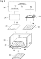
- Fig. 5 schematically shows a data processing system 26 where the data that define the model 10 are processed in the manner that has been described above in conjunction with Figs. 1 to 4 .
- the data that describe the base part 18 of the model are then transmitted to a forming implement 28, e.g. a CNC machine tool, where the data are used for controlling the machine tool so as to machine a blank (e.g. of wood, metal, plastics or any other suitable material) so as to obtain a base body 30 with a shape that has been defined by the base part 18 of the model.
- a forming implement 28 e.g. a CNC machine tool
- a blank e.g. of wood, metal, plastics or any other suitable material
- the data that describe the cover part, more particularly the transformed cover part 20' are transmitted to a printer 32, e.g. a flat bed ink jet printer that is capable of 3D or relief printing.
- the printer 32 is controlled to print a cover body 34 with a shape as defined by the cover part of the model data.
- the printer 32 is capable of printing with a high spatial resolution and is therefore capable of rendering the fine detail of the structured top surface 14'.
- the flat bottom surface of the cover body 34 (not visible in Fig. 5 ) is formed by the first layer of ink that is printed directly on the print surface of the printer 32.
- Fig. 5 further shows, in a sectioned perspective view, a vacuum forming implement 36 in which the base body 30 and the cover body 34 are joined together so as to form a three-dimensional object 38 with a shape as determined by the model 10.
- the vacuum forming implement 36 comprises a vacuum chamber 40 in which the base body 30 and the cover body 34 are positioned such that the cover body 34 overlays the top surface of the base body 30.
- a flexible bellows 42 covers the base body 30 and the cover body 34 and is sealed against a bottom wall of the vacuum chamber 20, so that the air between this bottom wall and the bellows 42 may be evacuated via suction holes 44. As a result, the bellows 42 shrinks and evenly presses the cover body 34 against the base body 30 on its entire surface.
- the cover body 34 is bent so that its bottom surface matches again the top surface of the base body 30 and the cover body as a whole reassumes the shape that is defined by the cover part 20 of the model in the non-transformed state as shown in Fig. 3 .
- the cover body may be firmly bonded to the base body, so that these components stick together in the final three-dimensional object 38.
- the base body 30 has the shape of a cylindrical lens, so that its top surface 22 is curved only in one dimension and, as a result, the flat, sheet-like cover body 34 can be smoothly wrapped around this surface.
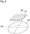
- the body of cured ink that constitutes the cover body 34 is stretchable to a certain extent, it is also possible to form three-dimensional objects in which the base body 30' is curved in two dimensions, as has been shown in Fig. 6 . Then, when the cover body 34, of which only a portion has been shown in Fig. 6 , is bonded to the top surface 22 of the base body 30', the cover body has to be stretched locally in order to adapt to the curved shape of the base body. This may lead to a minor distortion of the cover body 34 and, consequently, also of its textured top surface. In many cases these minor distortions will be tolerable. If a higher precision is required, it is also possible to compensate for these distortions by modifying the shape of the top surface 14' in the transformed version of the cover part 20' of the model such that the distortions which occur during vacuum forming restore the original shape of the top surface.
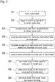
- step S1 the model data defining the model 10 are read into the data processing system 26 or are created directly in the data processing system.
- step S2 a smoothing algorithm, preferably a Laplacian smoothing algorithm is applied to the model 10 in order to obtain the base part 18 of the model.
- a smoothing algorithm preferably a Laplacian smoothing algorithm
- step S3 the base part 18 is subtracted from the original model 10, so that what remains is the cover part 20 of the model as shown in Fig. 3 .
- step S4 The transformation illustrated in Fig. 4 , for flattening the bottom side of the cover part, is applied in step S4, resulting in the transformed version of the cover part.
- step 5 which is preferably performed when the top surface of the base part is curved in two dimensions, the wrapping of the base body with the cover body is simulated in order to determine the amount by which the (elastic) cover body will be distorted (stretched), i.e. the amount by which each grid point will shift within the bottom surface of the cover part.
- the result may then be used in step S6 for applying an inverse distortion to the transformed version of the cover part 20' of the model, so that the original shape of the top surface 14 will be restored later in the vacuum forming step.
- step S7 any conventional forming technique is used for forming the base body 30 or 30' on the basis of the base part 18 of the model.
- step S8 the cover body 34 is printed with the flat bed printer 32 on the basis of the cover part 20' of the model data.
- the vacuum forming step S9 is performed for joining the base body and the cover body and bonding them together.
Landscapes
- Engineering & Computer Science (AREA)
- Chemical & Material Sciences (AREA)
- Materials Engineering (AREA)
- Manufacturing & Machinery (AREA)
- Mechanical Engineering (AREA)
- Physics & Mathematics (AREA)
- Optics & Photonics (AREA)
Abstract
a) splitting the model (10) into a high elevation / low resolution base part (18) and a low elevation / high resolution cover part (20');
b) forming a base body (30) with a shape as determined by the base part (18) of the model;
c) employing a 3D printing technique for printing a sheet-like cover body (34) with a shape as determined by the cover part (20') of the model; and
d) matching the cover body (34) to the base body (30) by vacuum forming.
Description
- The invention relates to a method of forming a three-dimensional object with a shape determined by model data defining a model of the object.
- Conventional methods of forming three-dimensional objects comprise for example injection molding, hand-molding and firing material such as clay or the like, and machining a solid blank of, e.g. wood or metal, e.g. by means of a CNC machine tool.
- Injection molding requires a specific mold and is therefore economical only in cases where a large number of objects with identical shape have to be formed. Hand-molding three-dimensional objects is laborious and requires a high skill.
- Machining operations for forming three-dimensional objects can become very complicated, especially when the object to be formed has a surface relief with fine detail.
- More recently, it has also become known to employ printing techniques, in particular ink jet printing, for forming three-dimensional objects by superposing several layers of curable ink. These techniques, which are termed "3D printing" or, if the elevation of the printed object is not too high, "2.5 D printing" or "relief printing". The term "3D printing" shall be used here as a generic term encompassing all these types of print process. The 3D printing techniques have the advantage that they permit to render fine details on the surface of the three-dimensional object and also permit to print a surface layer of the objects directly in the desired color.
- However, these techniques tend to become inefficient if the object to be formed has a very high elevation requiring that large amounts of ink have to be applied and cured in order to obtain a large-volume bulk body.
- Moreover, it is common practice to cure the ink by means of radiation, e.g. UV light. Then, when the elevation of the printed object increases, the curing lamps have to be arranged at a large distance above the print surface, so that there is a considerable risk of hazard.
- It is an object of the invention to provide a method of forming three-dimensional objects, which method involves printing techniques that are safer and/or more efficient.
- In order to achieve this object, the method according to the invention is characterized by the steps of:
- a) splitting the model into a high elevation / low resolution base part and a low elevation / high resolution cover part;
- b) forming a base body with a shape as determined by the base part of the model;
- c) employing a 3D printing technique for printing a sheet-like cover body with a shape as determined by the cover part of the model; and
- d) matching cover body to the base body by vacuum forming.
- The invention combines 3D printing techniques with conventional forming techniques. The more efficient conventional forming techniques are used for forming the base part which may have a high elevation but has only a low resolution, i.e. a relatively smooth surface, whereas the more detailed surface structure is provided by printing the sheet-like cover body, which will have a significantly lower elevation, so that it can safely and efficiently be printed with a 3D printer which is capable of rendering fine details of the surface structure with high spatial resolution. The three-dimensional object is then completed by using the well established vacuum forming technique for matching the cover body to the base body.
- More specific optional features of the invention are indicated in the dependent claims.
- It is preferred that, in the printing step c), an ink is used that retains a certain resiliency even in the cured state, so that the sheet-like cover body may be deformed to some extent in order to match the surface of the base body in the vacuum forming step d).
- If the surface of the base body is curved in two dimensions, it is further preferred that the cured ink has also elastic properties, so that the sheet-like cover body may be stretched locally in order to match the non-euclidian geometry of the base body surface.
- The model data defining the model of the object may be electronic data and may for example comprise the coordinates of grid points defining a grid model of the object. The step a) of splitting the model into the base part and the cover part may comprise applying a smoothing algorithm in order to obtain the low resolution base part. Then, the high resolution cover part may be obtained by subtracting the base part from the original model, optionally after having scaled down or clipped the base part to some extent so as to assure that the remaining cover part has a positive thickness at all grid points.
- The step b) of forming the base body may comprise any known forming techniques including additive techniques such as 3D printing (with a high production / low resolution 3D printer), as well as subtractive techniques using for example a flat bed cutter or a multi-axis machining system.
- In the printing step c) the ink may be applied onto a flexible and possibly stretchable substrate sheet to which the ink adheres, so that the substrate becomes part of the cover body. As an alternative, the ink may be printed directly onto the print surface of the printer, the print surface having a composition or coating ensuring that the ink will not adhere to the print surface, so that the printed cover body can be released easily.
- In the matching step d) the base body is used as a mold for suitably deforming the cover body.
- In one embodiment the step of vacuum forming may include bonding the cover body to the base body, so that the base body remains part of the three-dimensional object and assures that the vacuum-formed cover body retains its shape. In some applications where three-dimensional objects with similar general shapes are to be formed, it may be possible to perform the splitting step a) in such a way that the base parts for a plurality of objects have an identical shape and the objects differ only in the shape of their cover part. Then, a large number of identical base bodies may be formed efficiently, for example by means of injection molding, and the final objects are individualized by printing different cover bodies and vacuum forming them onto the base bodies.
- In a further development of the invention, it may be possible to employ an ink that is cured only partly in the printing step c), so that the ink body is still deformable to some extent, but can be cured further, e.g. by firing, in order to obtain a rigid body after the vacuum forming step d). In that case, the base body will serve only as a mold for vacuum forming and may be discarded afterwards, so that the resulting three-dimensional object is a hollow object consisting only of the cover body which retains its shape due to the last curing step after vacuum forming. This embodiment has the advantage that the step b) for forming the base body needs to be performed only once in a production process in which a plurality of three-dimensional objects with identical or similar shapes are formed.
- Embodiment examples will now be described in conjunction with the drawings, wherein:
- Fig. 1
- shows an example of a model of a three-dimensional object;
- Figs. 2 and 3
- illustrate a step of splitting the model shown in
Fig. 1 into a base part and a cover part; - Fig. 4
- illustrates a step of transforming the cover part of the model;
- Fig. 5
- is a diagram illustrating a workflow of a method according to the invention;
- Fig. 6
- is a perspective view of a base body and a part of a cover body of a three-dimensional object having a surface curved in two dimensions; and
- Fig. 7
- is a flow diagram showing essential steps of a method according to the invention.
-
Fig. 1 shows, in a vertical cross-section, amodel 10 of a three-dimensional object which is generally lens-shaped and has aflat bottom surface 12 and atextured top surface 14. Themodel 10 is a grid model in which a regular mesh of grid points is overlaid on thebottom surface 12, and thetextured top surface 14 is defined by assigning a height value to each grid point. The sectional view inFig. 1 shows only the grid points that are located within the sectional plane. For each of these grid points, aline 16 has been shown which connects the grid point on thebottom surface 12 to the corresponding point on thetop surface 14 - In
Fig. 2 themodel 10 is split into abase part 18 and anoverlying cover part 20. Thebase part 18 has a relatively large elevation and a relativelysmooth top surface 22 which can be obtained by applying a smoothing algorithm and slightly shrinking theoriginal model 10 shown inFig. 1 . More particularly, in this embodiment, the smoothing algorithm, e.g. Laplacian smoothing, has been applied to the grid points defining thetop surface 14, and the smoothened surface has been shifted downwards by a certain amount so as to shrink thebase part 18 and to assure that thetop surface 22 of the base part will nowhere exceed the height of thetop surface 14 of the model as a whole. - In
Fig. 3 thebase part 18 and thecover part 20 of the model have been shown separately. Thecover part 20 has a top surface identical with thetop surface 14 of the original model and acurved bottom surface 24 which matches thetop surface 22 of thebase part 18. -
Fig. 4 illustrates a transformation that is applied to thecover part 20 and which converts thecurved bottom surface 24 of the cover part into a flat bottom surface 24' while preserving the spatial relation (height difference) between thebottom surface 24 and thetop surface 14 at each grid point. The transformed cover part 20' is obtained by diminishing, at each grid point, the height of both the corresponding point on thebottom surface 24 and the corresponding point on thetop surface 14 by the height of thetop surface 22 of the base part 18 (Fig. 3 ) at the same grid point. -
Fig. 5 schematically shows adata processing system 26 where the data that define themodel 10 are processed in the manner that has been described above in conjunction withFigs. 1 to 4 . - The data that describe the
base part 18 of the model are then transmitted to a formingimplement 28, e.g. a CNC machine tool, where the data are used for controlling the machine tool so as to machine a blank (e.g. of wood, metal, plastics or any other suitable material) so as to obtain abase body 30 with a shape that has been defined by thebase part 18 of the model. - Similarly, the data that describe the cover part, more particularly the transformed cover part 20', are transmitted to a
printer 32, e.g. a flat bed ink jet printer that is capable of 3D or relief printing. On the basis of these data, theprinter 32 is controlled to print acover body 34 with a shape as defined by the cover part of the model data. Theprinter 32 is capable of printing with a high spatial resolution and is therefore capable of rendering the fine detail of the structured top surface 14'. The flat bottom surface of the cover body 34 (not visible inFig. 5 ) is formed by the first layer of ink that is printed directly on the print surface of theprinter 32. -
Fig. 5 further shows, in a sectioned perspective view, a vacuum forming implement 36 in which thebase body 30 and thecover body 34 are joined together so as to form a three-dimensional object 38 with a shape as determined by themodel 10. - Since the vacuum forming technology is well known, only a brief description will be given here. The vacuum forming implement 36 comprises a vacuum chamber 40 in which the
base body 30 and thecover body 34 are positioned such that thecover body 34 overlays the top surface of thebase body 30. A flexible bellows 42 covers thebase body 30 and thecover body 34 and is sealed against a bottom wall of thevacuum chamber 20, so that the air between this bottom wall and thebellows 42 may be evacuated via suction holes 44. As a result, thebellows 42 shrinks and evenly presses thecover body 34 against thebase body 30 on its entire surface. In this process, thecover body 34 is bent so that its bottom surface matches again the top surface of thebase body 30 and the cover body as a whole reassumes the shape that is defined by thecover part 20 of the model in the non-transformed state as shown inFig. 3 . - It will be understood that, by applying adhesive to the top surface of the
base body 30 and/or the bottom surface of thecover body 34, the cover body may be firmly bonded to the base body, so that these components stick together in the final three-dimensional object 38. - In the embodiment shown in
Fig. 5 , thebase body 30 has the shape of a cylindrical lens, so that itstop surface 22 is curved only in one dimension and, as a result, the flat, sheet-like cover body 34 can be smoothly wrapped around this surface. - If the body of cured ink that constitutes the
cover body 34 is stretchable to a certain extent, it is also possible to form three-dimensional objects in which the base body 30' is curved in two dimensions, as has been shown inFig. 6 . Then, when thecover body 34, of which only a portion has been shown inFig. 6 , is bonded to thetop surface 22 of the base body 30', the cover body has to be stretched locally in order to adapt to the curved shape of the base body. This may lead to a minor distortion of thecover body 34 and, consequently, also of its textured top surface. In many cases these minor distortions will be tolerable. If a higher precision is required, it is also possible to compensate for these distortions by modifying the shape of the top surface 14' in the transformed version of the cover part 20' of the model such that the distortions which occur during vacuum forming restore the original shape of the top surface. - Essential steps of a method according to the invention will now be described by reference to the flow diagram shown in
Fig. 7 . - In step S1, the model data defining the
model 10 are read into thedata processing system 26 or are created directly in the data processing system. - In step S2, a smoothing algorithm, preferably a Laplacian smoothing algorithm is applied to the
model 10 in order to obtain thebase part 18 of the model. - Then, in step S3, the
base part 18 is subtracted from theoriginal model 10, so that what remains is thecover part 20 of the model as shown inFig. 3 . - The transformation illustrated in
Fig. 4 , for flattening the bottom side of the cover part, is applied in step S4, resulting in the transformed version of the cover part. - In an optional step 5 which is preferably performed when the top surface of the base part is curved in two dimensions, the wrapping of the base body with the cover body is simulated in order to determine the amount by which the (elastic) cover body will be distorted (stretched), i.e. the amount by which each grid point will shift within the bottom surface of the cover part. The result may then be used in step S6 for applying an inverse distortion to the transformed version of the cover part 20' of the model, so that the original shape of the
top surface 14 will be restored later in the vacuum forming step. - In step S7, any conventional forming technique is used for forming the
base body 30 or 30' on the basis of thebase part 18 of the model. - In step S8, the
cover body 34 is printed with theflat bed printer 32 on the basis of the cover part 20' of the model data. - Finally, the vacuum forming step S9 is performed for joining the base body and the cover body and bonding them together.
Claims (9)
- A method of forming a three-dimensional object (38) with a shape determined by model data defining a model (10) of the object, characterized by the steps of:a) splitting the model (10) into a high elevation / low resolution base part (18) and a low elevation / high resolution cover part (20');b) forming a base body (30; 30') with a shape as determined by the base part (18) of the model;c) employing a 3D printing technique for printing a sheet-like cover body (34) with a shape as determined by the cover part (20') of the model; andd) matching cover body (34) to the base body (30; 30') by vacuum forming.
- The method according to claim 1, wherein an ink used in the printing step c) is selected to result in a cured ink body which constitutes the cover body (34) and has a certain resiliency.
- The method according to claim 2 wherein the ink is selected to result in a sheet-like cover body (34) which is stretchable.
- The method according to any of the preceding claims, wherein step a) comprises applying a smoothing algorithm to the model (10) in order to obtain the base part (18).
- The method according to claim 4, wherein the smoothing algorithm comprises Laplacian smoothing.
- The method according to any of the preceding claims, wherein the step c) is performed with a flat bed ink jet printer.
- The method according to any of the preceding claims, wherein, in step d), the cover body (34) is bonded to the base body (30; 30').
- A system for performing the method according to any of the preceding claims, the system comprising:- a data processing system (26) configured to perform step a);- a forming implement (28) adapted to form the base body (30; 30') on the basis of the base part (18) of the model;- an ink jet printer (32) for performing step c); and- a vacuum forming implement (36) adapted to perform step d).
- A computer program product comprising program code on a computer readable non-transitory medium, wherein the program code, when loaded into the data processing system (26) of the system according to claim 8, causes the data processing system to perform the step a).
Applications Claiming Priority (1)
| Application Number | Priority Date | Filing Date | Title |
|---|---|---|---|
| EP17180705 | 2017-07-11 |
Publications (2)
| Publication Number | Publication Date |
|---|---|
| EP3427919A1 true EP3427919A1 (en) | 2019-01-16 |
| EP3427919B1 EP3427919B1 (en) | 2021-08-11 |
Family
ID=59325161
Family Applications (1)
| Application Number | Title | Priority Date | Filing Date |
|---|---|---|---|
| EP18180714.0A Active EP3427919B1 (en) | 2017-07-11 | 2018-06-29 | Method and device of forming a three-dimensional object |
Country Status (2)
| Country | Link |
|---|---|
| US (1) | US10967567B2 (en) |
| EP (1) | EP3427919B1 (en) |
Families Citing this family (1)
| Publication number | Priority date | Publication date | Assignee | Title |
|---|---|---|---|---|
| US11292212B2 (en) * | 2018-10-11 | 2022-04-05 | X Development Llc | Hybrid additive manufacturing |
Citations (6)
| Publication number | Priority date | Publication date | Assignee | Title |
|---|---|---|---|---|
| CA2187123A1 (en) * | 1996-10-04 | 1998-04-04 | Pierre-Claude Aitcin | Mold made of porous concrete |
| EP1112828A1 (en) * | 1999-04-13 | 2001-07-04 | Angel Condes Condes | Method for manufacturing molds suitable for plastic injection |
| JP2003200487A (en) * | 2001-10-23 | 2003-07-15 | T S Tec Kk | Skin material having stitch design, vehicle seat, molding die for the skin material, manufacturing apparatus and manufacturing method for the vehicle seat |
| US20100102476A1 (en) * | 2008-10-29 | 2010-04-29 | Higgins Michael H | Method for manufacturing raised relief maps |
| US20160075090A1 (en) * | 2013-09-18 | 2016-03-17 | Disney Enterprises, Inc. | 3d printing with custom surface reflectance |
| CN105946205A (en) * | 2016-05-18 | 2016-09-21 | 浙江大学 | Calculable color texture thermoplastic molding method |
Family Cites Families (2)
| Publication number | Priority date | Publication date | Assignee | Title |
|---|---|---|---|---|
| US20050069682A1 (en) * | 2003-09-30 | 2005-03-31 | Tan Tseng | Custom 3-D Milled Object with Vacuum-Molded 2-D Printout Created from a 3-D Camera |
| BR112013015918B1 (en) | 2010-12-24 | 2020-02-11 | Unilever N.V. | WATER PURIFICATION COMPOSITION, WASH WATER PURIFICATION PROCESS AND KIT |
-
2018
- 2018-06-29 EP EP18180714.0A patent/EP3427919B1/en active Active
- 2018-07-03 US US16/026,567 patent/US10967567B2/en active Active
Patent Citations (6)
| Publication number | Priority date | Publication date | Assignee | Title |
|---|---|---|---|---|
| CA2187123A1 (en) * | 1996-10-04 | 1998-04-04 | Pierre-Claude Aitcin | Mold made of porous concrete |
| EP1112828A1 (en) * | 1999-04-13 | 2001-07-04 | Angel Condes Condes | Method for manufacturing molds suitable for plastic injection |
| JP2003200487A (en) * | 2001-10-23 | 2003-07-15 | T S Tec Kk | Skin material having stitch design, vehicle seat, molding die for the skin material, manufacturing apparatus and manufacturing method for the vehicle seat |
| US20100102476A1 (en) * | 2008-10-29 | 2010-04-29 | Higgins Michael H | Method for manufacturing raised relief maps |
| US20160075090A1 (en) * | 2013-09-18 | 2016-03-17 | Disney Enterprises, Inc. | 3d printing with custom surface reflectance |
| CN105946205A (en) * | 2016-05-18 | 2016-09-21 | 浙江大学 | Calculable color texture thermoplastic molding method |
Also Published As
| Publication number | Publication date |
|---|---|
| EP3427919B1 (en) | 2021-08-11 |
| US10967567B2 (en) | 2021-04-06 |
| US20190016044A1 (en) | 2019-01-17 |
Similar Documents
| Publication | Publication Date | Title |
|---|---|---|
| US11654623B2 (en) | Additive manufacturing system with layers of reinforcing mesh | |
| CN104875382B (en) | Three-dimensional printing method | |
| KR101407050B1 (en) | 3D printer using variable vat layer laminate method | |
| US20180194070A1 (en) | 3d printing using preformed reuseable support structure | |
| KR101722979B1 (en) | An Manufacturing Method of 3 Dimensional Shape | |
| JP2018118502A (en) | Three-dimensional printing method | |
| US10967567B2 (en) | Method of forming a three-dimensional object | |
| WO2015048276A1 (en) | A method of robot assisted automated decal application on complex three dimensional surfaces | |
| CN102602113A (en) | Decorative processing method for surface of large-size complex surface shell, surface shell and device | |
| CN110139757B (en) | Apparatus for producing objects by additive manufacturing and method of using the apparatus | |
| CN111032329B (en) | Decorative structure for the lining of a motor vehicle and method for producing such a decorative structure | |
| CN104441641A (en) | Stereo lithography apparatus (SLA)-based 3D printing implementation method and device | |
| TW201639711A (en) | Filming method and panel apparatus made thereof | |
| EP3274145B1 (en) | Processes for manufacturing parts employing additive manufacturing | |
| WO2022054350A1 (en) | Surface treatment method for modeled object | |
| US20190210153A1 (en) | Apparatus for producing an object by means of additive manufacturing and method of using the apparatus | |
| MX2025010497A (en) | Devices, systems, processes, and methods relating to 3d printers comprising pressurized resin production of three-dimensional target objects | |
| KR102272888B1 (en) | 3D printer with changing shape of printing plate and its operation method | |
| CN104985746A (en) | A film-covered injection molding process with silk-screen printed circuits | |
| CN115946463B (en) | UV transfer printing process and UV transfer printing tool | |
| CN107031264A (en) | Method for making pattern | |
| KR102028599B1 (en) | Method for transfering functional material layer on three-dimensional print object | |
| CN104511994A (en) | Film Thickness Uniformity Control Method for Embossing System | |
| CN103434079A (en) | Machining method for mobile phone model product part having carbon-fiber effect | |
| EP2942182A1 (en) | Method and system for applying a film to a plastic work piece that is to be cured, and a method for producing a plastic work piece |
Legal Events
| Date | Code | Title | Description |
|---|---|---|---|
| PUAI | Public reference made under article 153(3) epc to a published international application that has entered the european phase |
Free format text: ORIGINAL CODE: 0009012 |
|
| STAA | Information on the status of an ep patent application or granted ep patent |
Free format text: STATUS: THE APPLICATION HAS BEEN PUBLISHED |
|
| AK | Designated contracting states |
Kind code of ref document: A1 Designated state(s): AL AT BE BG CH CY CZ DE DK EE ES FI FR GB GR HR HU IE IS IT LI LT LU LV MC MK MT NL NO PL PT RO RS SE SI SK SM TR |
|
| AX | Request for extension of the european patent |
Extension state: BA ME |
|
| STAA | Information on the status of an ep patent application or granted ep patent |
Free format text: STATUS: REQUEST FOR EXAMINATION WAS MADE |
|
| 17P | Request for examination filed |
Effective date: 20190716 |
|
| RBV | Designated contracting states (corrected) |
Designated state(s): AL AT BE BG CH CY CZ DE DK EE ES FI FR GB GR HR HU IE IS IT LI LT LU LV MC MK MT NL NO PL PT RO RS SE SI SK SM TR |
|
| RAP1 | Party data changed (applicant data changed or rights of an application transferred) |
Owner name: CANON PRODUCTION PRINTING HOLDING B.V. |
|
| RAP1 | Party data changed (applicant data changed or rights of an application transferred) |
Owner name: CANON PRODUCTION PRINTING HOLDING B.V. |
|
| GRAP | Despatch of communication of intention to grant a patent |
Free format text: ORIGINAL CODE: EPIDOSNIGR1 |
|
| STAA | Information on the status of an ep patent application or granted ep patent |
Free format text: STATUS: GRANT OF PATENT IS INTENDED |
|
| RIC1 | Information provided on ipc code assigned before grant |
Ipc: B29C 64/188 20170101ALI20210219BHEP Ipc: B33Y 10/00 20150101ALI20210219BHEP Ipc: B29C 64/112 20170101ALI20210219BHEP Ipc: B29C 51/16 20060101ALI20210219BHEP Ipc: B33Y 30/00 20150101ALI20210219BHEP Ipc: B29C 64/245 20170101ALI20210219BHEP Ipc: B33Y 50/00 20150101ALI20210219BHEP Ipc: B29C 33/56 20060101ALI20210219BHEP Ipc: B29C 33/38 20060101ALI20210219BHEP Ipc: B29C 51/36 20060101AFI20210219BHEP Ipc: B29C 51/10 20060101ALI20210219BHEP Ipc: B33Y 40/00 20200101ALI20210219BHEP Ipc: B29C 33/18 20060101ALI20210219BHEP Ipc: B29L 31/40 20060101ALN20210219BHEP Ipc: B33Y 80/00 20150101ALI20210219BHEP |
|
| INTG | Intention to grant announced |
Effective date: 20210310 |
|
| GRAS | Grant fee paid |
Free format text: ORIGINAL CODE: EPIDOSNIGR3 |
|
| GRAA | (expected) grant |
Free format text: ORIGINAL CODE: 0009210 |
|
| STAA | Information on the status of an ep patent application or granted ep patent |
Free format text: STATUS: THE PATENT HAS BEEN GRANTED |
|
| AK | Designated contracting states |
Kind code of ref document: B1 Designated state(s): AL AT BE BG CH CY CZ DE DK EE ES FI FR GB GR HR HU IE IS IT LI LT LU LV MC MK MT NL NO PL PT RO RS SE SI SK SM TR |
|
| REG | Reference to a national code |
Ref country code: CH Ref legal event code: EP |
|
| REG | Reference to a national code |
Ref country code: DE Ref legal event code: R096 Ref document number: 602018021513 Country of ref document: DE |
|
| REG | Reference to a national code |
Ref country code: IE Ref legal event code: FG4D Ref country code: AT Ref legal event code: REF Ref document number: 1418934 Country of ref document: AT Kind code of ref document: T Effective date: 20210915 |
|
| REG | Reference to a national code |
Ref country code: NL Ref legal event code: FP |
|
| REG | Reference to a national code |
Ref country code: LT Ref legal event code: MG9D |
|
| REG | Reference to a national code |
Ref country code: AT Ref legal event code: MK05 Ref document number: 1418934 Country of ref document: AT Kind code of ref document: T Effective date: 20210811 |
|
| PG25 | Lapsed in a contracting state [announced via postgrant information from national office to epo] |
Ref country code: RS Free format text: LAPSE BECAUSE OF FAILURE TO SUBMIT A TRANSLATION OF THE DESCRIPTION OR TO PAY THE FEE WITHIN THE PRESCRIBED TIME-LIMIT Effective date: 20210811 Ref country code: SE Free format text: LAPSE BECAUSE OF FAILURE TO SUBMIT A TRANSLATION OF THE DESCRIPTION OR TO PAY THE FEE WITHIN THE PRESCRIBED TIME-LIMIT Effective date: 20210811 Ref country code: HR Free format text: LAPSE BECAUSE OF FAILURE TO SUBMIT A TRANSLATION OF THE DESCRIPTION OR TO PAY THE FEE WITHIN THE PRESCRIBED TIME-LIMIT Effective date: 20210811 Ref country code: ES Free format text: LAPSE BECAUSE OF FAILURE TO SUBMIT A TRANSLATION OF THE DESCRIPTION OR TO PAY THE FEE WITHIN THE PRESCRIBED TIME-LIMIT Effective date: 20210811 Ref country code: FI Free format text: LAPSE BECAUSE OF FAILURE TO SUBMIT A TRANSLATION OF THE DESCRIPTION OR TO PAY THE FEE WITHIN THE PRESCRIBED TIME-LIMIT Effective date: 20210811 Ref country code: NO Free format text: LAPSE BECAUSE OF FAILURE TO SUBMIT A TRANSLATION OF THE DESCRIPTION OR TO PAY THE FEE WITHIN THE PRESCRIBED TIME-LIMIT Effective date: 20211111 Ref country code: PT Free format text: LAPSE BECAUSE OF FAILURE TO SUBMIT A TRANSLATION OF THE DESCRIPTION OR TO PAY THE FEE WITHIN THE PRESCRIBED TIME-LIMIT Effective date: 20211213 Ref country code: LT Free format text: LAPSE BECAUSE OF FAILURE TO SUBMIT A TRANSLATION OF THE DESCRIPTION OR TO PAY THE FEE WITHIN THE PRESCRIBED TIME-LIMIT Effective date: 20210811 Ref country code: BG Free format text: LAPSE BECAUSE OF FAILURE TO SUBMIT A TRANSLATION OF THE DESCRIPTION OR TO PAY THE FEE WITHIN THE PRESCRIBED TIME-LIMIT Effective date: 20211111 Ref country code: AT Free format text: LAPSE BECAUSE OF FAILURE TO SUBMIT A TRANSLATION OF THE DESCRIPTION OR TO PAY THE FEE WITHIN THE PRESCRIBED TIME-LIMIT Effective date: 20210811 |
|
| PG25 | Lapsed in a contracting state [announced via postgrant information from national office to epo] |
Ref country code: PL Free format text: LAPSE BECAUSE OF FAILURE TO SUBMIT A TRANSLATION OF THE DESCRIPTION OR TO PAY THE FEE WITHIN THE PRESCRIBED TIME-LIMIT Effective date: 20210811 Ref country code: LV Free format text: LAPSE BECAUSE OF FAILURE TO SUBMIT A TRANSLATION OF THE DESCRIPTION OR TO PAY THE FEE WITHIN THE PRESCRIBED TIME-LIMIT Effective date: 20210811 Ref country code: GR Free format text: LAPSE BECAUSE OF FAILURE TO SUBMIT A TRANSLATION OF THE DESCRIPTION OR TO PAY THE FEE WITHIN THE PRESCRIBED TIME-LIMIT Effective date: 20211112 |
|
| PG25 | Lapsed in a contracting state [announced via postgrant information from national office to epo] |
Ref country code: DK Free format text: LAPSE BECAUSE OF FAILURE TO SUBMIT A TRANSLATION OF THE DESCRIPTION OR TO PAY THE FEE WITHIN THE PRESCRIBED TIME-LIMIT Effective date: 20210811 |
|
| REG | Reference to a national code |
Ref country code: DE Ref legal event code: R097 Ref document number: 602018021513 Country of ref document: DE |
|
| PG25 | Lapsed in a contracting state [announced via postgrant information from national office to epo] |
Ref country code: SM Free format text: LAPSE BECAUSE OF FAILURE TO SUBMIT A TRANSLATION OF THE DESCRIPTION OR TO PAY THE FEE WITHIN THE PRESCRIBED TIME-LIMIT Effective date: 20210811 Ref country code: SK Free format text: LAPSE BECAUSE OF FAILURE TO SUBMIT A TRANSLATION OF THE DESCRIPTION OR TO PAY THE FEE WITHIN THE PRESCRIBED TIME-LIMIT Effective date: 20210811 Ref country code: RO Free format text: LAPSE BECAUSE OF FAILURE TO SUBMIT A TRANSLATION OF THE DESCRIPTION OR TO PAY THE FEE WITHIN THE PRESCRIBED TIME-LIMIT Effective date: 20210811 Ref country code: EE Free format text: LAPSE BECAUSE OF FAILURE TO SUBMIT A TRANSLATION OF THE DESCRIPTION OR TO PAY THE FEE WITHIN THE PRESCRIBED TIME-LIMIT Effective date: 20210811 Ref country code: CZ Free format text: LAPSE BECAUSE OF FAILURE TO SUBMIT A TRANSLATION OF THE DESCRIPTION OR TO PAY THE FEE WITHIN THE PRESCRIBED TIME-LIMIT Effective date: 20210811 Ref country code: AL Free format text: LAPSE BECAUSE OF FAILURE TO SUBMIT A TRANSLATION OF THE DESCRIPTION OR TO PAY THE FEE WITHIN THE PRESCRIBED TIME-LIMIT Effective date: 20210811 |
|
| PLBE | No opposition filed within time limit |
Free format text: ORIGINAL CODE: 0009261 |
|
| STAA | Information on the status of an ep patent application or granted ep patent |
Free format text: STATUS: NO OPPOSITION FILED WITHIN TIME LIMIT |
|
| 26N | No opposition filed |
Effective date: 20220512 |
|
| PG25 | Lapsed in a contracting state [announced via postgrant information from national office to epo] |
Ref country code: IT Free format text: LAPSE BECAUSE OF FAILURE TO SUBMIT A TRANSLATION OF THE DESCRIPTION OR TO PAY THE FEE WITHIN THE PRESCRIBED TIME-LIMIT Effective date: 20210811 |
|
| PG25 | Lapsed in a contracting state [announced via postgrant information from national office to epo] |
Ref country code: SI Free format text: LAPSE BECAUSE OF FAILURE TO SUBMIT A TRANSLATION OF THE DESCRIPTION OR TO PAY THE FEE WITHIN THE PRESCRIBED TIME-LIMIT Effective date: 20210811 |
|
| PG25 | Lapsed in a contracting state [announced via postgrant information from national office to epo] |
Ref country code: MC Free format text: LAPSE BECAUSE OF FAILURE TO SUBMIT A TRANSLATION OF THE DESCRIPTION OR TO PAY THE FEE WITHIN THE PRESCRIBED TIME-LIMIT Effective date: 20210811 |
|
| REG | Reference to a national code |
Ref country code: CH Ref legal event code: PL |
|
| REG | Reference to a national code |
Ref country code: BE Ref legal event code: MM Effective date: 20220630 |
|
| PG25 | Lapsed in a contracting state [announced via postgrant information from national office to epo] |
Ref country code: LU Free format text: LAPSE BECAUSE OF NON-PAYMENT OF DUE FEES Effective date: 20220629 Ref country code: LI Free format text: LAPSE BECAUSE OF NON-PAYMENT OF DUE FEES Effective date: 20220630 Ref country code: IE Free format text: LAPSE BECAUSE OF NON-PAYMENT OF DUE FEES Effective date: 20220629 Ref country code: CH Free format text: LAPSE BECAUSE OF NON-PAYMENT OF DUE FEES Effective date: 20220630 |
|
| PG25 | Lapsed in a contracting state [announced via postgrant information from national office to epo] |
Ref country code: BE Free format text: LAPSE BECAUSE OF NON-PAYMENT OF DUE FEES Effective date: 20220630 |
|
| PG25 | Lapsed in a contracting state [announced via postgrant information from national office to epo] |
Ref country code: HU Free format text: LAPSE BECAUSE OF FAILURE TO SUBMIT A TRANSLATION OF THE DESCRIPTION OR TO PAY THE FEE WITHIN THE PRESCRIBED TIME-LIMIT; INVALID AB INITIO Effective date: 20180629 |
|
| PG25 | Lapsed in a contracting state [announced via postgrant information from national office to epo] |
Ref country code: MK Free format text: LAPSE BECAUSE OF FAILURE TO SUBMIT A TRANSLATION OF THE DESCRIPTION OR TO PAY THE FEE WITHIN THE PRESCRIBED TIME-LIMIT Effective date: 20210811 Ref country code: CY Free format text: LAPSE BECAUSE OF FAILURE TO SUBMIT A TRANSLATION OF THE DESCRIPTION OR TO PAY THE FEE WITHIN THE PRESCRIBED TIME-LIMIT Effective date: 20210811 |
|
| PG25 | Lapsed in a contracting state [announced via postgrant information from national office to epo] |
Ref country code: MT Free format text: LAPSE BECAUSE OF FAILURE TO SUBMIT A TRANSLATION OF THE DESCRIPTION OR TO PAY THE FEE WITHIN THE PRESCRIBED TIME-LIMIT Effective date: 20210811 |
|
| PGFP | Annual fee paid to national office [announced via postgrant information from national office to epo] |
Ref country code: NL Payment date: 20250519 Year of fee payment: 8 |
|
| PGFP | Annual fee paid to national office [announced via postgrant information from national office to epo] |
Ref country code: DE Payment date: 20250618 Year of fee payment: 8 |
|
| PGFP | Annual fee paid to national office [announced via postgrant information from national office to epo] |
Ref country code: GB Payment date: 20250618 Year of fee payment: 8 |
|
| PGFP | Annual fee paid to national office [announced via postgrant information from national office to epo] |
Ref country code: FR Payment date: 20250625 Year of fee payment: 8 |
|
| PG25 | Lapsed in a contracting state [announced via postgrant information from national office to epo] |
Ref country code: TR Free format text: LAPSE BECAUSE OF FAILURE TO SUBMIT A TRANSLATION OF THE DESCRIPTION OR TO PAY THE FEE WITHIN THE PRESCRIBED TIME-LIMIT Effective date: 20210811 |