EP3427675A1 - Cartouche d'agrafes comprenant un couvercle libérable - Google Patents
Cartouche d'agrafes comprenant un couvercle libérable Download PDFInfo
- Publication number
- EP3427675A1 EP3427675A1 EP18179845.5A EP18179845A EP3427675A1 EP 3427675 A1 EP3427675 A1 EP 3427675A1 EP 18179845 A EP18179845 A EP 18179845A EP 3427675 A1 EP3427675 A1 EP 3427675A1
- Authority
- EP
- European Patent Office
- Prior art keywords
- staple
- thickness compensator
- tissue thickness
- cartridge
- staple cartridge
- Prior art date
- Legal status (The legal status is an assumption and is not a legal conclusion. Google has not performed a legal analysis and makes no representation as to the accuracy of the status listed.)
- Granted
Links
- 239000012636 effector Substances 0.000 claims description 254
- 238000009434 installation Methods 0.000 claims description 12
- 210000001519 tissue Anatomy 0.000 description 1266
- 239000010410 layer Substances 0.000 description 652
- 238000010304 firing Methods 0.000 description 440
- 230000009969 flowable effect Effects 0.000 description 165
- 239000000203 mixture Substances 0.000 description 153
- 238000005520 cutting process Methods 0.000 description 152
- 230000001070 adhesive effect Effects 0.000 description 81
- 239000000463 material Substances 0.000 description 81
- 239000000853 adhesive Substances 0.000 description 80
- 230000014759 maintenance of location Effects 0.000 description 74
- 229920000954 Polyglycolide Polymers 0.000 description 72
- 230000036961 partial effect Effects 0.000 description 72
- 239000004633 polyglycolic acid Substances 0.000 description 70
- PAPBSGBWRJIAAV-UHFFFAOYSA-N ε-Caprolactone Chemical compound O=C1CCCCCO1 PAPBSGBWRJIAAV-UHFFFAOYSA-N 0.000 description 57
- 239000004820 Pressure-sensitive adhesive Substances 0.000 description 55
- 230000033001 locomotion Effects 0.000 description 50
- 239000000758 substrate Substances 0.000 description 46
- -1 poly(lactic acid) Polymers 0.000 description 43
- 229920001610 polycaprolactone Polymers 0.000 description 38
- 239000004632 polycaprolactone Substances 0.000 description 38
- 238000000034 method Methods 0.000 description 36
- 230000007246 mechanism Effects 0.000 description 31
- 230000006835 compression Effects 0.000 description 23
- 238000007906 compression Methods 0.000 description 23
- 229920001577 copolymer Polymers 0.000 description 23
- 239000011800 void material Substances 0.000 description 20
- 238000010521 absorption reaction Methods 0.000 description 18
- 230000000670 limiting effect Effects 0.000 description 18
- 230000008569 process Effects 0.000 description 18
- RKDVKSZUMVYZHH-UHFFFAOYSA-N 1,4-dioxane-2,5-dione Chemical compound O=C1COC(=O)CO1 RKDVKSZUMVYZHH-UHFFFAOYSA-N 0.000 description 17
- 239000011324 bead Substances 0.000 description 14
- 230000000717 retained effect Effects 0.000 description 14
- 238000010586 diagram Methods 0.000 description 13
- 239000011148 porous material Substances 0.000 description 13
- 229920000642 polymer Polymers 0.000 description 12
- JVTAAEKCZFNVCJ-REOHCLBHSA-N L-lactic acid Chemical compound C[C@H](O)C(O)=O JVTAAEKCZFNVCJ-REOHCLBHSA-N 0.000 description 11
- 239000006260 foam Substances 0.000 description 11
- 238000003780 insertion Methods 0.000 description 11
- 230000037431 insertion Effects 0.000 description 11
- 229920001432 poly(L-lactide) Polymers 0.000 description 11
- 229920001198 elastomeric copolymer Polymers 0.000 description 10
- JJTUDXZGHPGLLC-UHFFFAOYSA-N lactide Chemical compound CC1OC(=O)C(C)OC1=O JJTUDXZGHPGLLC-UHFFFAOYSA-N 0.000 description 10
- 230000008859 change Effects 0.000 description 9
- 239000011159 matrix material Substances 0.000 description 9
- 230000002829 reductive effect Effects 0.000 description 9
- VPVXHAANQNHFSF-UHFFFAOYSA-N 1,4-dioxan-2-one Chemical compound O=C1COCCO1 VPVXHAANQNHFSF-UHFFFAOYSA-N 0.000 description 8
- 230000035882 stress Effects 0.000 description 8
- JVTAAEKCZFNVCJ-UHFFFAOYSA-N Lactic Acid Natural products CC(O)C(O)=O JVTAAEKCZFNVCJ-UHFFFAOYSA-N 0.000 description 7
- 230000000994 depressogenic effect Effects 0.000 description 7
- 229920001059 synthetic polymer Polymers 0.000 description 7
- OUYCCCASQSFEME-QMMMGPOBSA-N L-tyrosine Chemical compound OC(=O)[C@@H](N)CC1=CC=C(O)C=C1 OUYCCCASQSFEME-QMMMGPOBSA-N 0.000 description 6
- 230000000295 complement effect Effects 0.000 description 6
- 230000000694 effects Effects 0.000 description 6
- 150000004676 glycans Chemical class 0.000 description 6
- 239000004417 polycarbonate Substances 0.000 description 6
- 229920000515 polycarbonate Polymers 0.000 description 6
- 229920001282 polysaccharide Polymers 0.000 description 6
- 239000005017 polysaccharide Substances 0.000 description 6
- 230000007704 transition Effects 0.000 description 6
- YFHICDDUDORKJB-UHFFFAOYSA-N trimethylene carbonate Chemical compound O=C1OCCCO1 YFHICDDUDORKJB-UHFFFAOYSA-N 0.000 description 6
- OUYCCCASQSFEME-UHFFFAOYSA-N tyrosine Natural products OC(=O)C(N)CC1=CC=C(O)C=C1 OUYCCCASQSFEME-UHFFFAOYSA-N 0.000 description 6
- JJTUDXZGHPGLLC-IMJSIDKUSA-N 4511-42-6 Chemical compound C[C@@H]1OC(=O)[C@H](C)OC1=O JJTUDXZGHPGLLC-IMJSIDKUSA-N 0.000 description 5
- 230000036760 body temperature Effects 0.000 description 5
- 210000003811 finger Anatomy 0.000 description 5
- 239000004310 lactic acid Substances 0.000 description 5
- 235000014655 lactic acid Nutrition 0.000 description 5
- 210000003739 neck Anatomy 0.000 description 5
- 229920000747 poly(lactic acid) Polymers 0.000 description 5
- 229920000139 polyethylene terephthalate Polymers 0.000 description 5
- 239000005020 polyethylene terephthalate Substances 0.000 description 5
- 239000012858 resilient material Substances 0.000 description 5
- 239000007787 solid Substances 0.000 description 5
- 229910001220 stainless steel Inorganic materials 0.000 description 5
- 239000010935 stainless steel Substances 0.000 description 5
- 238000003466 welding Methods 0.000 description 5
- 102000016942 Elastin Human genes 0.000 description 4
- 108010014258 Elastin Proteins 0.000 description 4
- 239000002202 Polyethylene glycol Substances 0.000 description 4
- 230000005540 biological transmission Effects 0.000 description 4
- 239000003814 drug Substances 0.000 description 4
- 229920002549 elastin Polymers 0.000 description 4
- 229920001971 elastomer Polymers 0.000 description 4
- 239000000835 fiber Substances 0.000 description 4
- 239000011521 glass Substances 0.000 description 4
- 229920001308 poly(aminoacid) Polymers 0.000 description 4
- 229920000728 polyester Polymers 0.000 description 4
- 229920001223 polyethylene glycol Polymers 0.000 description 4
- 230000000284 resting effect Effects 0.000 description 4
- 238000000926 separation method Methods 0.000 description 4
- 238000012546 transfer Methods 0.000 description 4
- 102000008186 Collagen Human genes 0.000 description 3
- 108010035532 Collagen Proteins 0.000 description 3
- 108010010803 Gelatin Proteins 0.000 description 3
- 102000003886 Glycoproteins Human genes 0.000 description 3
- 108090000288 Glycoproteins Proteins 0.000 description 3
- 239000004677 Nylon Substances 0.000 description 3
- 239000004698 Polyethylene Substances 0.000 description 3
- 229920000331 Polyhydroxybutyrate Polymers 0.000 description 3
- 239000004743 Polypropylene Substances 0.000 description 3
- 102000016611 Proteoglycans Human genes 0.000 description 3
- 108010067787 Proteoglycans Proteins 0.000 description 3
- 229920004738 ULTEM® Polymers 0.000 description 3
- 230000008901 benefit Effects 0.000 description 3
- 239000000560 biocompatible material Substances 0.000 description 3
- 230000015556 catabolic process Effects 0.000 description 3
- 239000011248 coating agent Substances 0.000 description 3
- 238000000576 coating method Methods 0.000 description 3
- 229920001436 collagen Polymers 0.000 description 3
- 238000006731 degradation reaction Methods 0.000 description 3
- 239000000945 filler Substances 0.000 description 3
- 230000006870 function Effects 0.000 description 3
- 239000008273 gelatin Substances 0.000 description 3
- 229920000159 gelatin Polymers 0.000 description 3
- 235000019322 gelatine Nutrition 0.000 description 3
- 235000011852 gelatine desserts Nutrition 0.000 description 3
- 239000000017 hydrogel Substances 0.000 description 3
- 238000002513 implantation Methods 0.000 description 3
- 230000003993 interaction Effects 0.000 description 3
- 239000007769 metal material Substances 0.000 description 3
- 230000007935 neutral effect Effects 0.000 description 3
- 229920001778 nylon Polymers 0.000 description 3
- 229920002463 poly(p-dioxanone) polymer Polymers 0.000 description 3
- 239000000622 polydioxanone Substances 0.000 description 3
- 229920000573 polyethylene Polymers 0.000 description 3
- 229920001155 polypropylene Polymers 0.000 description 3
- 229920002635 polyurethane Polymers 0.000 description 3
- 239000004814 polyurethane Substances 0.000 description 3
- 238000003825 pressing Methods 0.000 description 3
- 239000004627 regenerated cellulose Substances 0.000 description 3
- 230000004044 response Effects 0.000 description 3
- 238000013519 translation Methods 0.000 description 3
- KKGSHHDRPRINNY-UHFFFAOYSA-N 1,4-dioxan-2-one Chemical compound O=C1COCCO1.O=C1COCCO1 KKGSHHDRPRINNY-UHFFFAOYSA-N 0.000 description 2
- 239000004812 Fluorinated ethylene propylene Substances 0.000 description 2
- 229920000106 Liquid crystal polymer Polymers 0.000 description 2
- 239000004977 Liquid-crystal polymers (LCPs) Substances 0.000 description 2
- 239000004696 Poly ether ether ketone Substances 0.000 description 2
- 229920002732 Polyanhydride Polymers 0.000 description 2
- 229920001710 Polyorthoester Polymers 0.000 description 2
- 229910000831 Steel Inorganic materials 0.000 description 2
- RTAQQCXQSZGOHL-UHFFFAOYSA-N Titanium Chemical compound [Ti] RTAQQCXQSZGOHL-UHFFFAOYSA-N 0.000 description 2
- 229910052782 aluminium Inorganic materials 0.000 description 2
- XAGFODPZIPBFFR-UHFFFAOYSA-N aluminium Chemical compound [Al] XAGFODPZIPBFFR-UHFFFAOYSA-N 0.000 description 2
- 238000013459 approach Methods 0.000 description 2
- 230000015572 biosynthetic process Effects 0.000 description 2
- 210000001124 body fluid Anatomy 0.000 description 2
- 239000002775 capsule Substances 0.000 description 2
- 230000008878 coupling Effects 0.000 description 2
- 238000010168 coupling process Methods 0.000 description 2
- 238000005859 coupling reaction Methods 0.000 description 2
- 239000000806 elastomer Substances 0.000 description 2
- 229920000295 expanded polytetrafluoroethylene Polymers 0.000 description 2
- 239000000499 gel Substances 0.000 description 2
- 230000000977 initiatory effect Effects 0.000 description 2
- 210000004072 lung Anatomy 0.000 description 2
- 238000004519 manufacturing process Methods 0.000 description 2
- 229910052751 metal Inorganic materials 0.000 description 2
- 239000002184 metal Substances 0.000 description 2
- 238000012986 modification Methods 0.000 description 2
- 230000004048 modification Effects 0.000 description 2
- GKTNLYAAZKKMTQ-UHFFFAOYSA-N n-[bis(dimethylamino)phosphinimyl]-n-methylmethanamine Chemical compound CN(C)P(=N)(N(C)C)N(C)C GKTNLYAAZKKMTQ-UHFFFAOYSA-N 0.000 description 2
- 229920005615 natural polymer Polymers 0.000 description 2
- 229920009441 perflouroethylene propylene Polymers 0.000 description 2
- 230000002093 peripheral effect Effects 0.000 description 2
- 239000004014 plasticizer Substances 0.000 description 2
- 229920001279 poly(ester amides) Polymers 0.000 description 2
- 239000005014 poly(hydroxyalkanoate) Substances 0.000 description 2
- 229920001230 polyarylate Polymers 0.000 description 2
- 229920002530 polyetherether ketone Polymers 0.000 description 2
- 229920001343 polytetrafluoroethylene Polymers 0.000 description 2
- 239000004810 polytetrafluoroethylene Substances 0.000 description 2
- 229920000166 polytrimethylene carbonate Polymers 0.000 description 2
- 239000004800 polyvinyl chloride Substances 0.000 description 2
- 229920002620 polyvinyl fluoride Polymers 0.000 description 2
- 239000005060 rubber Substances 0.000 description 2
- 239000010959 steel Substances 0.000 description 2
- 238000001356 surgical procedure Methods 0.000 description 2
- 238000003856 thermoforming Methods 0.000 description 2
- 239000010936 titanium Substances 0.000 description 2
- 229910052719 titanium Inorganic materials 0.000 description 2
- 230000001960 triggered effect Effects 0.000 description 2
- KIUKXJAPPMFGSW-DNGZLQJQSA-N (2S,3S,4S,5R,6R)-6-[(2S,3R,4R,5S,6R)-3-Acetamido-2-[(2S,3S,4R,5R,6R)-6-[(2R,3R,4R,5S,6R)-3-acetamido-2,5-dihydroxy-6-(hydroxymethyl)oxan-4-yl]oxy-2-carboxy-4,5-dihydroxyoxan-3-yl]oxy-5-hydroxy-6-(hydroxymethyl)oxan-4-yl]oxy-3,4,5-trihydroxyoxane-2-carboxylic acid Chemical compound CC(=O)N[C@H]1[C@H](O)O[C@H](CO)[C@@H](O)[C@@H]1O[C@H]1[C@H](O)[C@@H](O)[C@H](O[C@H]2[C@@H]([C@@H](O[C@H]3[C@@H]([C@@H](O)[C@H](O)[C@H](O3)C(O)=O)O)[C@H](O)[C@@H](CO)O2)NC(C)=O)[C@@H](C(O)=O)O1 KIUKXJAPPMFGSW-DNGZLQJQSA-N 0.000 description 1
- BYEAHWXPCBROCE-UHFFFAOYSA-N 1,1,1,3,3,3-hexafluoropropan-2-ol Chemical compound FC(F)(F)C(O)C(F)(F)F BYEAHWXPCBROCE-UHFFFAOYSA-N 0.000 description 1
- MFRCZYUUKMFJQJ-UHFFFAOYSA-N 1,4-dioxane-2,5-dione;1,3-dioxan-2-one Chemical compound O=C1OCCCO1.O=C1COC(=O)CO1 MFRCZYUUKMFJQJ-UHFFFAOYSA-N 0.000 description 1
- LCSKNASZPVZHEG-UHFFFAOYSA-N 3,6-dimethyl-1,4-dioxane-2,5-dione;1,4-dioxane-2,5-dione Chemical compound O=C1COC(=O)CO1.CC1OC(=O)C(C)OC1=O LCSKNASZPVZHEG-UHFFFAOYSA-N 0.000 description 1
- SQDAZGGFXASXDW-UHFFFAOYSA-N 5-bromo-2-(trifluoromethoxy)pyridine Chemical compound FC(F)(F)OC1=CC=C(Br)C=N1 SQDAZGGFXASXDW-UHFFFAOYSA-N 0.000 description 1
- FHVDTGUDJYJELY-UHFFFAOYSA-N 6-{[2-carboxy-4,5-dihydroxy-6-(phosphanyloxy)oxan-3-yl]oxy}-4,5-dihydroxy-3-phosphanyloxane-2-carboxylic acid Chemical compound O1C(C(O)=O)C(P)C(O)C(O)C1OC1C(C(O)=O)OC(OP)C(O)C1O FHVDTGUDJYJELY-UHFFFAOYSA-N 0.000 description 1
- 229920000936 Agarose Polymers 0.000 description 1
- 229920002284 Cellulose triacetate Polymers 0.000 description 1
- 229920001661 Chitosan Polymers 0.000 description 1
- 229920001287 Chondroitin sulfate Polymers 0.000 description 1
- 239000004971 Cross linker Substances 0.000 description 1
- 229920004937 Dexon® Polymers 0.000 description 1
- 239000001856 Ethyl cellulose Substances 0.000 description 1
- ZZSNKZQZMQGXPY-UHFFFAOYSA-N Ethyl cellulose Chemical compound CCOCC1OC(OC)C(OCC)C(OCC)C1OC1C(O)C(O)C(OC)C(CO)O1 ZZSNKZQZMQGXPY-UHFFFAOYSA-N 0.000 description 1
- JOYRKODLDBILNP-UHFFFAOYSA-N Ethyl urethane Chemical compound CCOC(N)=O JOYRKODLDBILNP-UHFFFAOYSA-N 0.000 description 1
- IWDQPCIQCXRBQP-UHFFFAOYSA-M Fenaminosulf Chemical compound [Na+].CN(C)C1=CC=C(N=NS([O-])(=O)=O)C=C1 IWDQPCIQCXRBQP-UHFFFAOYSA-M 0.000 description 1
- 102000009123 Fibrin Human genes 0.000 description 1
- 108010073385 Fibrin Proteins 0.000 description 1
- BWGVNKXGVNDBDI-UHFFFAOYSA-N Fibrin monomer Chemical compound CNC(=O)CNC(=O)CN BWGVNKXGVNDBDI-UHFFFAOYSA-N 0.000 description 1
- 102000008946 Fibrinogen Human genes 0.000 description 1
- 108010049003 Fibrinogen Proteins 0.000 description 1
- 102000016359 Fibronectins Human genes 0.000 description 1
- 108010067306 Fibronectins Proteins 0.000 description 1
- AEMRFAOFKBGASW-UHFFFAOYSA-N Glycolic acid Polymers OCC(O)=O AEMRFAOFKBGASW-UHFFFAOYSA-N 0.000 description 1
- 229920000544 Gore-Tex Polymers 0.000 description 1
- 102000001554 Hemoglobins Human genes 0.000 description 1
- 108010054147 Hemoglobins Proteins 0.000 description 1
- 229920000663 Hydroxyethyl cellulose Polymers 0.000 description 1
- 239000004354 Hydroxyethyl cellulose Substances 0.000 description 1
- 229920001612 Hydroxyethyl starch Polymers 0.000 description 1
- 229920002153 Hydroxypropyl cellulose Polymers 0.000 description 1
- 108010058846 Ovalbumin Proteins 0.000 description 1
- 229920003171 Poly (ethylene oxide) Polymers 0.000 description 1
- 229930182556 Polyacetal Natural products 0.000 description 1
- 239000004952 Polyamide Substances 0.000 description 1
- 239000004793 Polystyrene Substances 0.000 description 1
- 239000004372 Polyvinyl alcohol Substances 0.000 description 1
- 235000004443 Ricinus communis Nutrition 0.000 description 1
- 240000000528 Ricinus communis Species 0.000 description 1
- 108010071390 Serum Albumin Proteins 0.000 description 1
- 102000007562 Serum Albumin Human genes 0.000 description 1
- 229920002125 Sokalan® Polymers 0.000 description 1
- NNLVGZFZQQXQNW-ADJNRHBOSA-N [(2r,3r,4s,5r,6s)-4,5-diacetyloxy-3-[(2s,3r,4s,5r,6r)-3,4,5-triacetyloxy-6-(acetyloxymethyl)oxan-2-yl]oxy-6-[(2r,3r,4s,5r,6s)-4,5,6-triacetyloxy-2-(acetyloxymethyl)oxan-3-yl]oxyoxan-2-yl]methyl acetate Chemical compound O([C@@H]1O[C@@H]([C@H]([C@H](OC(C)=O)[C@H]1OC(C)=O)O[C@H]1[C@@H]([C@@H](OC(C)=O)[C@H](OC(C)=O)[C@@H](COC(C)=O)O1)OC(C)=O)COC(=O)C)[C@@H]1[C@@H](COC(C)=O)O[C@@H](OC(C)=O)[C@H](OC(C)=O)[C@H]1OC(C)=O NNLVGZFZQQXQNW-ADJNRHBOSA-N 0.000 description 1
- 230000009471 action Effects 0.000 description 1
- 239000013543 active substance Substances 0.000 description 1
- 238000004026 adhesive bonding Methods 0.000 description 1
- 239000012790 adhesive layer Substances 0.000 description 1
- 230000032683 aging Effects 0.000 description 1
- 229940072056 alginate Drugs 0.000 description 1
- 229920000615 alginic acid Polymers 0.000 description 1
- 235000010443 alginic acid Nutrition 0.000 description 1
- 229940030225 antihemorrhagics Drugs 0.000 description 1
- 239000003963 antioxidant agent Substances 0.000 description 1
- QVGXLLKOCUKJST-UHFFFAOYSA-N atomic oxygen Chemical compound [O] QVGXLLKOCUKJST-UHFFFAOYSA-N 0.000 description 1
- 229920002988 biodegradable polymer Polymers 0.000 description 1
- 239000004621 biodegradable polymer Substances 0.000 description 1
- 229920001400 block copolymer Polymers 0.000 description 1
- 230000000903 blocking effect Effects 0.000 description 1
- 238000005219 brazing Methods 0.000 description 1
- 239000001913 cellulose Substances 0.000 description 1
- 229920002678 cellulose Polymers 0.000 description 1
- 229920002301 cellulose acetate Polymers 0.000 description 1
- 239000000919 ceramic Substances 0.000 description 1
- 238000003486 chemical etching Methods 0.000 description 1
- 229940059329 chondroitin sulfate Drugs 0.000 description 1
- 239000003086 colorant Substances 0.000 description 1
- 239000002131 composite material Substances 0.000 description 1
- 238000000748 compression moulding Methods 0.000 description 1
- 238000001816 cooling Methods 0.000 description 1
- 238000013461 design Methods 0.000 description 1
- 238000007607 die coating method Methods 0.000 description 1
- 238000003618 dip coating Methods 0.000 description 1
- 239000000975 dye Substances 0.000 description 1
- 238000000609 electron-beam lithography Methods 0.000 description 1
- HQQADJVZYDDRJT-UHFFFAOYSA-N ethene;prop-1-ene Chemical group C=C.CC=C HQQADJVZYDDRJT-UHFFFAOYSA-N 0.000 description 1
- 229920001249 ethyl cellulose Polymers 0.000 description 1
- 235000019325 ethyl cellulose Nutrition 0.000 description 1
- 229950003499 fibrin Drugs 0.000 description 1
- 229940012952 fibrinogen Drugs 0.000 description 1
- 230000009477 glass transition Effects 0.000 description 1
- 230000000025 haemostatic effect Effects 0.000 description 1
- 230000035876 healing Effects 0.000 description 1
- 230000023597 hemostasis Effects 0.000 description 1
- 230000002439 hemostatic effect Effects 0.000 description 1
- 229920002674 hyaluronan Polymers 0.000 description 1
- 229960003160 hyaluronic acid Drugs 0.000 description 1
- 235000019447 hydroxyethyl cellulose Nutrition 0.000 description 1
- 229940071826 hydroxyethyl cellulose Drugs 0.000 description 1
- 229940050526 hydroxyethylstarch Drugs 0.000 description 1
- 239000001863 hydroxypropyl cellulose Substances 0.000 description 1
- 235000010977 hydroxypropyl cellulose Nutrition 0.000 description 1
- 229940071676 hydroxypropylcellulose Drugs 0.000 description 1
- 239000007943 implant Substances 0.000 description 1
- 238000001727 in vivo Methods 0.000 description 1
- 238000007373 indentation Methods 0.000 description 1
- AMGQUBHHOARCQH-UHFFFAOYSA-N indium;oxotin Chemical compound [In].[Sn]=O AMGQUBHHOARCQH-UHFFFAOYSA-N 0.000 description 1
- 238000005304 joining Methods 0.000 description 1
- 238000012830 laparoscopic surgical procedure Methods 0.000 description 1
- 238000010329 laser etching Methods 0.000 description 1
- 230000007774 longterm Effects 0.000 description 1
- 230000013011 mating Effects 0.000 description 1
- 238000012978 minimally invasive surgical procedure Methods 0.000 description 1
- IFVGFQAONSKBCR-UHFFFAOYSA-N n-[bis(aziridin-1-yl)phosphoryl]pyrimidin-2-amine Chemical compound C1CN1P(N1CC1)(=O)NC1=NC=CC=N1 IFVGFQAONSKBCR-UHFFFAOYSA-N 0.000 description 1
- 238000002355 open surgical procedure Methods 0.000 description 1
- 229940092253 ovalbumin Drugs 0.000 description 1
- 229910052760 oxygen Inorganic materials 0.000 description 1
- 239000001301 oxygen Substances 0.000 description 1
- 230000035515 penetration Effects 0.000 description 1
- 238000000206 photolithography Methods 0.000 description 1
- 239000000049 pigment Substances 0.000 description 1
- 229920003023 plastic Polymers 0.000 description 1
- 239000004033 plastic Substances 0.000 description 1
- 239000002985 plastic film Substances 0.000 description 1
- 229920006255 plastic film Polymers 0.000 description 1
- 229920001245 poly(D,L-lactide-co-caprolactone) Polymers 0.000 description 1
- 239000005015 poly(hydroxybutyrate) Substances 0.000 description 1
- 229920003229 poly(methyl methacrylate) Polymers 0.000 description 1
- 229920002492 poly(sulfone) Polymers 0.000 description 1
- 229920002401 polyacrylamide Polymers 0.000 description 1
- 239000004584 polyacrylic acid Substances 0.000 description 1
- 229920002647 polyamide Polymers 0.000 description 1
- 229920001195 polyisoprene Polymers 0.000 description 1
- 229920006324 polyoxymethylene Polymers 0.000 description 1
- 229920001296 polysiloxane Polymers 0.000 description 1
- 229920002451 polyvinyl alcohol Polymers 0.000 description 1
- 229920000915 polyvinyl chloride Polymers 0.000 description 1
- 239000001267 polyvinylpyrrolidone Substances 0.000 description 1
- 235000013855 polyvinylpyrrolidone Nutrition 0.000 description 1
- 230000002250 progressing effect Effects 0.000 description 1
- 230000002685 pulmonary effect Effects 0.000 description 1
- 230000009467 reduction Effects 0.000 description 1
- 238000007761 roller coating Methods 0.000 description 1
- 210000004872 soft tissue Anatomy 0.000 description 1
- 238000004528 spin coating Methods 0.000 description 1
- 238000009987 spinning Methods 0.000 description 1
- 238000005507 spraying Methods 0.000 description 1
- 239000003381 stabilizer Substances 0.000 description 1
- 230000000087 stabilizing effect Effects 0.000 description 1
- 238000007655 standard test method Methods 0.000 description 1
- 238000010345 tape casting Methods 0.000 description 1
- 229940124597 therapeutic agent Drugs 0.000 description 1
- 210000003813 thumb Anatomy 0.000 description 1
- 230000000007 visual effect Effects 0.000 description 1
Images


Classifications
-
- A—HUMAN NECESSITIES
- A61—MEDICAL OR VETERINARY SCIENCE; HYGIENE
- A61B—DIAGNOSIS; SURGERY; IDENTIFICATION
- A61B17/00—Surgical instruments, devices or methods, e.g. tourniquets
- A61B17/068—Surgical staplers, e.g. containing multiple staples or clamps
- A61B17/0682—Surgical staplers, e.g. containing multiple staples or clamps for applying U-shaped staples or clamps, e.g. without a forming anvil
-
- A—HUMAN NECESSITIES
- A61—MEDICAL OR VETERINARY SCIENCE; HYGIENE
- A61B—DIAGNOSIS; SURGERY; IDENTIFICATION
- A61B17/00—Surgical instruments, devices or methods, e.g. tourniquets
- A61B17/064—Surgical staples, i.e. penetrating the tissue
- A61B17/0644—Surgical staples, i.e. penetrating the tissue penetrating the tissue, deformable to closed position
-
- A—HUMAN NECESSITIES
- A61—MEDICAL OR VETERINARY SCIENCE; HYGIENE
- A61B—DIAGNOSIS; SURGERY; IDENTIFICATION
- A61B17/00—Surgical instruments, devices or methods, e.g. tourniquets
- A61B17/068—Surgical staplers, e.g. containing multiple staples or clamps
-
- A—HUMAN NECESSITIES
- A61—MEDICAL OR VETERINARY SCIENCE; HYGIENE
- A61B—DIAGNOSIS; SURGERY; IDENTIFICATION
- A61B17/00—Surgical instruments, devices or methods, e.g. tourniquets
- A61B17/068—Surgical staplers, e.g. containing multiple staples or clamps
- A61B17/072—Surgical staplers, e.g. containing multiple staples or clamps for applying a row of staples in a single action, e.g. the staples being applied simultaneously
- A61B17/07207—Surgical staplers, e.g. containing multiple staples or clamps for applying a row of staples in a single action, e.g. the staples being applied simultaneously the staples being applied sequentially
-
- A—HUMAN NECESSITIES
- A61—MEDICAL OR VETERINARY SCIENCE; HYGIENE
- A61B—DIAGNOSIS; SURGERY; IDENTIFICATION
- A61B17/00—Surgical instruments, devices or methods, e.g. tourniquets
- A61B17/068—Surgical staplers, e.g. containing multiple staples or clamps
- A61B17/072—Surgical staplers, e.g. containing multiple staples or clamps for applying a row of staples in a single action, e.g. the staples being applied simultaneously
- A61B17/07292—Reinforcements for staple line, e.g. pledgets
-
- A—HUMAN NECESSITIES
- A61—MEDICAL OR VETERINARY SCIENCE; HYGIENE
- A61B—DIAGNOSIS; SURGERY; IDENTIFICATION
- A61B17/00—Surgical instruments, devices or methods, e.g. tourniquets
- A61B2017/00004—(bio)absorbable, (bio)resorbable, resorptive
-
- A—HUMAN NECESSITIES
- A61—MEDICAL OR VETERINARY SCIENCE; HYGIENE
- A61B—DIAGNOSIS; SURGERY; IDENTIFICATION
- A61B17/00—Surgical instruments, devices or methods, e.g. tourniquets
- A61B2017/0046—Surgical instruments, devices or methods, e.g. tourniquets with a releasable handle; with handle and operating part separable
- A61B2017/00473—Distal part, e.g. tip or head
-
- A—HUMAN NECESSITIES
- A61—MEDICAL OR VETERINARY SCIENCE; HYGIENE
- A61B—DIAGNOSIS; SURGERY; IDENTIFICATION
- A61B17/00—Surgical instruments, devices or methods, e.g. tourniquets
- A61B2017/00477—Coupling
-
- A—HUMAN NECESSITIES
- A61—MEDICAL OR VETERINARY SCIENCE; HYGIENE
- A61B—DIAGNOSIS; SURGERY; IDENTIFICATION
- A61B17/00—Surgical instruments, devices or methods, e.g. tourniquets
- A61B2017/00526—Methods of manufacturing
-
- A—HUMAN NECESSITIES
- A61—MEDICAL OR VETERINARY SCIENCE; HYGIENE
- A61B—DIAGNOSIS; SURGERY; IDENTIFICATION
- A61B17/00—Surgical instruments, devices or methods, e.g. tourniquets
- A61B2017/00526—Methods of manufacturing
- A61B2017/0053—Loading magazines or sutures into applying tools
-
- A—HUMAN NECESSITIES
- A61—MEDICAL OR VETERINARY SCIENCE; HYGIENE
- A61B—DIAGNOSIS; SURGERY; IDENTIFICATION
- A61B17/00—Surgical instruments, devices or methods, e.g. tourniquets
- A61B2017/00743—Type of operation; Specification of treatment sites
- A61B2017/00818—Treatment of the gastro-intestinal system
-
- A—HUMAN NECESSITIES
- A61—MEDICAL OR VETERINARY SCIENCE; HYGIENE
- A61B—DIAGNOSIS; SURGERY; IDENTIFICATION
- A61B17/00—Surgical instruments, devices or methods, e.g. tourniquets
- A61B2017/00831—Material properties
- A61B2017/00862—Material properties elastic or resilient
-
- A—HUMAN NECESSITIES
- A61—MEDICAL OR VETERINARY SCIENCE; HYGIENE
- A61B—DIAGNOSIS; SURGERY; IDENTIFICATION
- A61B17/00—Surgical instruments, devices or methods, e.g. tourniquets
- A61B2017/00831—Material properties
- A61B2017/00884—Material properties enhancing wound closure
-
- A—HUMAN NECESSITIES
- A61—MEDICAL OR VETERINARY SCIENCE; HYGIENE
- A61B—DIAGNOSIS; SURGERY; IDENTIFICATION
- A61B17/00—Surgical instruments, devices or methods, e.g. tourniquets
- A61B2017/00831—Material properties
- A61B2017/00893—Material properties pharmaceutically effective
-
- A—HUMAN NECESSITIES
- A61—MEDICAL OR VETERINARY SCIENCE; HYGIENE
- A61B—DIAGNOSIS; SURGERY; IDENTIFICATION
- A61B17/00—Surgical instruments, devices or methods, e.g. tourniquets
- A61B2017/00831—Material properties
- A61B2017/00951—Material properties adhesive
-
- A—HUMAN NECESSITIES
- A61—MEDICAL OR VETERINARY SCIENCE; HYGIENE
- A61B—DIAGNOSIS; SURGERY; IDENTIFICATION
- A61B17/00—Surgical instruments, devices or methods, e.g. tourniquets
- A61B2017/00831—Material properties
- A61B2017/00964—Material properties composite
-
- A—HUMAN NECESSITIES
- A61—MEDICAL OR VETERINARY SCIENCE; HYGIENE
- A61B—DIAGNOSIS; SURGERY; IDENTIFICATION
- A61B17/00—Surgical instruments, devices or methods, e.g. tourniquets
- A61B17/064—Surgical staples, i.e. penetrating the tissue
- A61B2017/0641—Surgical staples, i.e. penetrating the tissue having at least three legs as part of one single body
-
- A—HUMAN NECESSITIES
- A61—MEDICAL OR VETERINARY SCIENCE; HYGIENE
- A61B—DIAGNOSIS; SURGERY; IDENTIFICATION
- A61B17/00—Surgical instruments, devices or methods, e.g. tourniquets
- A61B17/068—Surgical staplers, e.g. containing multiple staples or clamps
- A61B17/072—Surgical staplers, e.g. containing multiple staples or clamps for applying a row of staples in a single action, e.g. the staples being applied simultaneously
- A61B2017/07214—Stapler heads
- A61B2017/07228—Arrangement of the staples
-
- A—HUMAN NECESSITIES
- A61—MEDICAL OR VETERINARY SCIENCE; HYGIENE
- A61B—DIAGNOSIS; SURGERY; IDENTIFICATION
- A61B17/00—Surgical instruments, devices or methods, e.g. tourniquets
- A61B17/068—Surgical staplers, e.g. containing multiple staples or clamps
- A61B17/072—Surgical staplers, e.g. containing multiple staples or clamps for applying a row of staples in a single action, e.g. the staples being applied simultaneously
- A61B2017/07214—Stapler heads
- A61B2017/07235—Stapler heads containing different staples, e.g. staples of different shapes, sizes or materials
-
- A—HUMAN NECESSITIES
- A61—MEDICAL OR VETERINARY SCIENCE; HYGIENE
- A61B—DIAGNOSIS; SURGERY; IDENTIFICATION
- A61B17/00—Surgical instruments, devices or methods, e.g. tourniquets
- A61B17/068—Surgical staplers, e.g. containing multiple staples or clamps
- A61B17/072—Surgical staplers, e.g. containing multiple staples or clamps for applying a row of staples in a single action, e.g. the staples being applied simultaneously
- A61B2017/07214—Stapler heads
- A61B2017/07242—Stapler heads achieving different staple heights during the same shot, e.g. using an anvil anvil having different heights or staples of different sizes
-
- A—HUMAN NECESSITIES
- A61—MEDICAL OR VETERINARY SCIENCE; HYGIENE
- A61B—DIAGNOSIS; SURGERY; IDENTIFICATION
- A61B17/00—Surgical instruments, devices or methods, e.g. tourniquets
- A61B17/068—Surgical staplers, e.g. containing multiple staples or clamps
- A61B17/072—Surgical staplers, e.g. containing multiple staples or clamps for applying a row of staples in a single action, e.g. the staples being applied simultaneously
- A61B2017/07214—Stapler heads
- A61B2017/0725—Stapler heads with settable gap between anvil and cartridge, e.g. for different staple heights at different shots
-
- A—HUMAN NECESSITIES
- A61—MEDICAL OR VETERINARY SCIENCE; HYGIENE
- A61B—DIAGNOSIS; SURGERY; IDENTIFICATION
- A61B17/00—Surgical instruments, devices or methods, e.g. tourniquets
- A61B17/068—Surgical staplers, e.g. containing multiple staples or clamps
- A61B17/072—Surgical staplers, e.g. containing multiple staples or clamps for applying a row of staples in a single action, e.g. the staples being applied simultaneously
- A61B2017/07214—Stapler heads
- A61B2017/07257—Stapler heads characterised by its anvil
-
- A—HUMAN NECESSITIES
- A61—MEDICAL OR VETERINARY SCIENCE; HYGIENE
- A61B—DIAGNOSIS; SURGERY; IDENTIFICATION
- A61B17/00—Surgical instruments, devices or methods, e.g. tourniquets
- A61B17/068—Surgical staplers, e.g. containing multiple staples or clamps
- A61B17/072—Surgical staplers, e.g. containing multiple staples or clamps for applying a row of staples in a single action, e.g. the staples being applied simultaneously
- A61B2017/07214—Stapler heads
- A61B2017/07271—Stapler heads characterised by its cartridge
-
- A—HUMAN NECESSITIES
- A61—MEDICAL OR VETERINARY SCIENCE; HYGIENE
- A61B—DIAGNOSIS; SURGERY; IDENTIFICATION
- A61B17/00—Surgical instruments, devices or methods, e.g. tourniquets
- A61B17/068—Surgical staplers, e.g. containing multiple staples or clamps
- A61B17/072—Surgical staplers, e.g. containing multiple staples or clamps for applying a row of staples in a single action, e.g. the staples being applied simultaneously
- A61B2017/07214—Stapler heads
- A61B2017/07278—Stapler heads characterised by its sled or its staple holder
-
- A—HUMAN NECESSITIES
- A61—MEDICAL OR VETERINARY SCIENCE; HYGIENE
- A61B—DIAGNOSIS; SURGERY; IDENTIFICATION
- A61B17/00—Surgical instruments, devices or methods, e.g. tourniquets
- A61B17/068—Surgical staplers, e.g. containing multiple staples or clamps
- A61B17/072—Surgical staplers, e.g. containing multiple staples or clamps for applying a row of staples in a single action, e.g. the staples being applied simultaneously
- A61B2017/07214—Stapler heads
- A61B2017/07285—Stapler heads characterised by its cutter
-
- A—HUMAN NECESSITIES
- A61—MEDICAL OR VETERINARY SCIENCE; HYGIENE
- A61B—DIAGNOSIS; SURGERY; IDENTIFICATION
- A61B17/00—Surgical instruments, devices or methods, e.g. tourniquets
- A61B17/28—Surgical forceps
- A61B17/29—Forceps for use in minimally invasive surgery
- A61B17/2909—Handles
- A61B2017/2912—Handles transmission of forces to actuating rod or piston
- A61B2017/2923—Toothed members, e.g. rack and pinion
-
- A—HUMAN NECESSITIES
- A61—MEDICAL OR VETERINARY SCIENCE; HYGIENE
- A61B—DIAGNOSIS; SURGERY; IDENTIFICATION
- A61B17/00—Surgical instruments, devices or methods, e.g. tourniquets
- A61B17/28—Surgical forceps
- A61B17/29—Forceps for use in minimally invasive surgery
- A61B17/2909—Handles
- A61B2017/2925—Pistol grips
-
- A—HUMAN NECESSITIES
- A61—MEDICAL OR VETERINARY SCIENCE; HYGIENE
- A61B—DIAGNOSIS; SURGERY; IDENTIFICATION
- A61B17/00—Surgical instruments, devices or methods, e.g. tourniquets
- A61B17/28—Surgical forceps
- A61B17/29—Forceps for use in minimally invasive surgery
- A61B2017/2926—Details of heads or jaws
- A61B2017/2927—Details of heads or jaws the angular position of the head being adjustable with respect to the shaft
-
- A—HUMAN NECESSITIES
- A61—MEDICAL OR VETERINARY SCIENCE; HYGIENE
- A61B—DIAGNOSIS; SURGERY; IDENTIFICATION
- A61B17/00—Surgical instruments, devices or methods, e.g. tourniquets
- A61B17/28—Surgical forceps
- A61B17/29—Forceps for use in minimally invasive surgery
- A61B2017/2926—Details of heads or jaws
- A61B2017/2932—Transmission of forces to jaw members
- A61B2017/2933—Transmission of forces to jaw members camming or guiding means
- A61B2017/2936—Pins in guiding slots
-
- A—HUMAN NECESSITIES
- A61—MEDICAL OR VETERINARY SCIENCE; HYGIENE
- A61B—DIAGNOSIS; SURGERY; IDENTIFICATION
- A61B17/00—Surgical instruments, devices or methods, e.g. tourniquets
- A61B17/32—Surgical cutting instruments
- A61B2017/320052—Guides for cutting instruments
-
- A—HUMAN NECESSITIES
- A61—MEDICAL OR VETERINARY SCIENCE; HYGIENE
- A61B—DIAGNOSIS; SURGERY; IDENTIFICATION
- A61B90/00—Instruments, implements or accessories specially adapted for surgery or diagnosis and not covered by any of the groups A61B1/00 - A61B50/00, e.g. for luxation treatment or for protecting wound edges
- A61B90/03—Automatic limiting or abutting means, e.g. for safety
- A61B2090/033—Abutting means, stops, e.g. abutting on tissue or skin
- A61B2090/034—Abutting means, stops, e.g. abutting on tissue or skin abutting on parts of the device itself
-
- A—HUMAN NECESSITIES
- A61—MEDICAL OR VETERINARY SCIENCE; HYGIENE
- A61B—DIAGNOSIS; SURGERY; IDENTIFICATION
- A61B90/00—Instruments, implements or accessories specially adapted for surgery or diagnosis and not covered by any of the groups A61B1/00 - A61B50/00, e.g. for luxation treatment or for protecting wound edges
- A61B90/03—Automatic limiting or abutting means, e.g. for safety
- A61B2090/037—Automatic limiting or abutting means, e.g. for safety with a frangible part, e.g. by reduced diameter
Definitions
- the present invention relates to surgical instruments and, in various embodiments, to surgical cutting and stapling instruments and staple cartridges therefor that are designed to cut and staple tissue.
- a first embodiment of the present invention comprises a staple cartridge for use with an end effector of a surgical stapler, wherein the end effector includes a staple cartridge channel configured to receive said staple cartridge, said staple cartridge comprising:
- FIGS. 169 to 173 which includes a retainer as shown in FIG. 168 .
- the layer of the first embodiment is discussed in paragraphs [0469] and [0470], for example.
- a second embodiment of the present invention comprises a staple cartridge for use with an end effector of a surgical stapler, wherein the end effector includes a staple cartridge channel configured to receive said staple cartridge, said staple cartridge comprising:
- FIGS. 169 to 173 which includes a retainer as shown in FIG. 168 .
- the layer of the second embodiment is discussed in paragraphs [0469] and [0470], for example.
- a third embodiment of the present invention comprises a staple cartridge for use with a surgical stapler, said staple cartridge comprising:
- FIGS. 169 to 173 A staple cartridge according to the third embodiment of the present invention is shown in FIGS. 169 to 173 , where the retainer shown in FIG. 168 comprises the cover of the third embodiment of the present invention.
- the layer of the third embodiment is discussed in paragraphs [0469] and [0470], for example.
- a fourth embodiment of the present invention provides a staple cartridge for use with a surgical stapler, said staple cartridge comprising:
- FIGS. 169 to 173 A staple cartridge according to the fourth embodiment of the present invention is shown in FIGS. 169 to 173 , where the retainer shown in FIG. 168 comprises the cover of the fourth embodiment of the present invention.
- Portions 2616 comprise the first and second lateral portions, and locking tabs 2626 comprise the first and second locks.
- the layer is discussed in paragraphs [0469] and [0470], for example.
- a fifth embodiment of the present invention provides a staple cartridge for use with a surgical stapler, said staple cartridge comprising:
- FIGS. 169 to 173 A staple cartridge according to the fifth embodiment of the present invention is shown in FIGS. 169 to 173 , where the retainer shown in FIG. 168 comprises the cover of the fifth embodiment of the present invention.
- Portions 2616 comprise the installation lock which engage a key in the staple cartridge channel 2670. The layer is discussed in paragraphs [0469] and [0470], for example.
- proximal and distal are used herein with reference to a clinician manipulating the handle portion of the surgical instrument.
- proximal referring to the portion closest to the clinician and the term “distal” referring to the portion located away from the clinician.
- distal referring to the portion located away from the clinician.
- spatial terms such as “vertical”, “horizontal”, “up”, and “down” may be used herein with respect to the drawings.
- surgical instruments are used in many orientations and positions, and these terms are not intended to be limiting and/or absolute.
- a surgical stapling and severing instrument 8010 can comprise an anvil 8014 which may be repeatably opened and closed about its pivotal attachment to an elongate staple channel 8016.
- a staple applying assembly 8012 can comprise the anvil 8014 and the channel 8016, wherein the assembly 8012 can be proximally attached to the elongate shaft 8018 forming an implement portion 8022.
- the implement portion 8022 can present a sufficiently small cross-section suitable for inserting the staple applying assembly 8012 through a trocar.
- the assembly 8012 can be manipulated by a handle 8020 connected to the shaft 8018.
- the handle 8020 can comprise user controls such as a rotation knob 8030 that rotates the elongate shaft 8018 and staple applying assembly 8012 about a longitudinal axis of the shaft 8018.
- a closure trigger 8026 which can pivot in front of a pistol grip 8036 about a closure trigger pin 8152 ( FIG. 3 ) engaged laterally across the handle housing 8154, can be depressed to close the staple applying assembly 8012.
- a closure release button 8038 can be outwardly presented on the handle 8020 when the closure trigger 8026 is clamped such that the release button 8038 can be depressed to unclamp the closure trigger 8026 and open the staple applying assembly 8012, as described in greater detail below.
- a firing trigger 8034 which can pivot in front of the closure trigger 8026, can cause the staple applying assembly 8012 to simultaneously sever and staple tissue clamped therein.
- multiple firing strokes can be employed using the firing trigger 8034 to reduce the amount of force required to be applied by the surgeon's hand per stroke.
- the handle 8020 can comprise rotatable right and/or left indicator wheels 8040, 8041 ( FIG. 3 ) which can indicate the firing progress. For instance, full firing travel may require three full firing strokes of firing trigger 8034 and thus the indicator wheels 8040, 8041 can rotate up to one-third of a revolution each per stroke of firing trigger 8034.
- a manual firing release lever 8042 can allow the firing system to be retracted before full firing travel has been completed, if desired, and, in addition, the firing release lever 8042 can allow a surgeon, or other clinician, to retract the firing system in the event that the firing system binds and/or fails.
- the elongate shaft 8018 can comprise an outer structure including a longitudinally reciprocating closure tube 8024 that pivots the anvil 8014 toward its close position in response to the proximal depression of the closure trigger 8026 of handle 8020.
- the elongate channel 8018 can be connected to the handle 8020 by a frame 8028 ( FIG. 3 ) that is internal to the closure tube 8024.
- the frame 8028 can be rotatably engaged to the handle 8020 so that the rotation of the rotation knob 8030 ( FIG. 1 ) can rotate the implement portion 8022.
- the rotation knob 8030 can be comprised of two half-shells which can include one or more inward projections 8031 that can extend through one or more elongate side openings 8070 in the closure tube 8024 and engage the frame 8028.
- the rotation knob 8030 and the frame 8028 can be rotated together, or synchronously, such that the rotated position of knob 8030 determines the rotated position of the implement portion 8022.
- the longitudinal length of the longer opening 8070 is sufficiently long to allow the longitudinal closure motion, and opening motion, of the closure tube 8024.
- an upper portion 8160 of the closure trigger 8026 can push forward a closure yoke 8162 ( FIG. 4 ) via a closure link 8164.
- the closure link 8164 is pivotally attached at its distal end by a closure yoke pin 8166 to the closure yoke 8162 and is pivotally attached at its proximal end by a closure link pin 8168.
- the closure trigger 8026 can be urged to an open position by a closure trigger tension spring 8246 that is connected proximally to the upper portion 8160 of the closure trigger 8026 and a handle housing 8154 formed by right and left half shells 8156, 8158.
- the tension force applied by the tension spring 8246 can be overcome by a closing force applied to the closure trigger 8026 in order to advance the yoke 8162, closure link 8164, and the closure tube 8024 distally.
- the closure release button 8038 can be positioned such that the surgeon, or other clinician, can push the closure release button 8038, if desired, and allow the closure trigger 8026, and the rest of the surgical instrument, to return to an unactuated state.
- the closure release button 8038 can be connected to a pivoting locking arm 8172 by a central lateral pivot 8173 such that motion can be transferred between the release button 8038 and the locking arm 8172.
- a compression spring 8174 can bias the closure release button 8038 proximally, i.e., clockwise about the central lateral pivot 8173 as viewed from the right and the upper portion 8160 of the closure trigger 8026 can include a proximal crest 8170 with an aft notch 8171.
- the pivoting locking arm 8172 can ride upon the proximal crest 8170 and when the closure trigger 8026 reaches its fully depressed position, it should be appreciated that the aft notch 8171 is presented below the pivoting locking arm 8172 which drops into and locks against the aft notch 8171 under the urging of the compression spring 8174.
- manual depression of the closure release button 8038 rotates the pivoting locking arm 8172 upward and out of aft notch 8171 thereby unlocking the closure trigger 8026 and allowing the closure trigger 8026 to be returned to its unclamped position.
- the firing trigger 8034 can be drawn toward the pistol grip 8036 in order to advance a firing rod 8032 distally from the handle 8020.
- the firing trigger 8034 can pivot about a firing trigger pin 8202 that laterally traverses and is engaged with the right and left half shells 8156, 8158 of the handle 8020.
- the firing trigger 8034 when actuated, can advance a linked transmission firing mechanism 8150.
- the linked transmission firing mechanism 8150 can be urged into a retracted, unfired, position by a spring 8184 that is, one, attached to the pistol grip 8036 of the handle 8020 and, two, attached to one of the links, for example, of the linked transmission firing mechanism 8150 as described in greater detail below.
- the spring 8184 can comprise a nonmoving end 8186 connected to the housing 8154 and a moving end 8188 connected to a proximal end 8190 of a steel band 8192.
- a distally-disposed end 8194 of the steel band 8192 can be attached to an attachment feature 8195 on a front link 8196a of a plurality of links 8196a -8196d that form a linked rack 8200.
- Linked rack 8200 can be flexible such that it can readily retract into the pistol grip 8036 and minimize the length of the handle 8020 and yet form a straight rigid rack assembly that may transfer a significant firing force to and/or through the firing rod 8032.
- the firing trigger 8034 can be engaged with a first link 8196a during a first actuation of the firing trigger 8034, engaged with a second link 8196b during a second actuation of the firing trigger 8034, engaged with a third link 8196c during a third actuation of the firing trigger 8034, and engaged with a fourth link 8196d during a fourth actuation of the firing trigger 8034, wherein each actuation of the firing trigger 8034 can advance the linked rack 8200 distally an incremental amount.
- the multiple strokes of firing trigger 8034 can rotate the right and left indicator gauge wheels 8040, 8041 to indicate the distance in which the linked rack 8200 has been advanced.
- an anti-backup mechanism 8250 can prevent the combination tension/compression spring 8184 from retracting the linked rack 8200 between firing strokes.
- a coupling slide tube 8131 abuts the first link 8196a and connects to the firing rod 8032 to communicate the firing motion.
- the firing rod 8032 extends proximally out of a proximal end of the frame 8028 and through a through hole 8408 of an anti-backup plate 8266.
- the through hole 8408 is sized to slidingly receive the firing rod 8032 when perpendicularly aligned but to bind when tipped.
- a lower tab attachment 8271 extends proximally from a lower lip of the proximal end of the frame 8028, extending through an aperture 8269 on a lower edge of the anti-backup plate 8266.
- This lower tab attachment 8271 draws the lower portion of the anti-backup plate 8266 proximate to the frame 8028 so that the anti-backup plate 8266 is perpendicular when the firing rod 8032 is distally advanced and allowed to tip top aft into a binding state when the firing rod 8032 attempts to retract.
- An anti-backup compression spring 8264 is distally constrained by the proximal end of the frame 8028 and proximally abuts a top portion of the anti-backup plate 8266, biasing the anti-backup plate 8266 to a locking state.
- an anti-backup cam tube 8268 slidingly encompasses the coupling slide tube 8131 and abuts the anti-backup plate 8266.
- a proximally projecting anti-backup yoke 8256 attached to the anti-backup cam tube 8268 extends overtop of the closure yoke 8162.
- a link triggered automatic retraction mechanism 8289 is incorporated into the surgical stapling and severing instrument 8010 to cause knife retraction at the end of full firing travel.
- the distal link 8196d includes a tang 8290 that projects upwardly when the distal link 8196d is advanced into rack channel 8291 ( FIG. 3 ) formed in the closure yoke 8162. This tang 8290 is aligned to activate a bottom proximal cam 8292 on an anti-backup release lever 8248 ( FIG. 6 ).
- structures formed in the right and left half shells 8156, 8158 constrain movement of the anti-backup release lever 8248.
- a pin receptacle 8296 and circular pin 8293 formed respectively between right and left half shells 8156, 8158 is received through a longitudinally elongate aperture 8294 formed in the anti-backup release lever 8248 distal to the bottom proximal cam 8292, thus allowing longitudinal translation as well as rotation about the circular pin 8293.
- a proximally open channel includes a proximal horizontal portion that communicates with an upwardly and distally angled portion that receives a rightward aft pin 8297 near the proximal end of the anti-backup release lever 8248, thus imparting an upward rotation as the anti-backup release lever 8248 reaches the distal most portion of its translation.
- a blocking structure formed in the right half shell 8156 proximal to the anti-backup release lever 8248 prevents proximal movement thereof once assembled to maintain rightward aft pin 8297 in the proximally open channel, discussed above.
- a distal end 8254 of the anti-backup release lever 8248 thus is urged distally and downwardly, causing a rightward front pin 8298 to drop into distally open step structure 8299 formed in the right half shell 8156, which is urged into this engagement by a compression spring 8300 ( FIG. 3 ) hooked to a leftward hook 8301 on the anti-backup release lever 8248 between the rightward front pin 8298 and the longitudinally elongate aperture 8294.
- the other end of the compression spring 8300 is attached to a hook 8302 ( FIG.
- the compression spring 8300 thus pulls the distal end 8254 of the anti-backup release lever 8248 down and aft, which results in the rightward front pin 8298 locking into the distally open step structure 8299 when distally advanced.
- the anti-backup release lever 8248 remains forward holding the anti-backup plate 8266 perpendicularly and thus allowing the linked rack 8200 to be retracted.
- the firing trigger 8034 can be operably engaged to the linked rack 8200 in any suitable manner.
- the firing trigger 8034 pivots about a firing trigger pin 8202 that is connected to the housing 8154.
- An upper portion 8204 of the firing trigger 8034 moves distally about the firing trigger pin 8202 as the firing trigger 8034 is depressed towards pistol grip 8036, stretching a proximally placed firing trigger tension spring 8206 ( FIG. 3 ) proximally connected between the upper portion 8204 of the firing trigger 8034 and the housing 8154.
- the upper portion 8204 of the firing trigger 8034 engages the linked rack 8200 during each firing trigger depression via a spring biased side pawl mechanism 8210.
- a ramped right-side track formed by a proximally and rightwardly facing beveled surface 8284 in each of the links 8196a-8196d is engaged by a side pawl assembly 8285.
- a pawl slide 8270 FIGS. 3 and 4
- a compression spring 8278 is attached between a hook 8279 on a top proximal position on the closure yoke rail 8276 and a hook 8280 on a distal right-side of the pawl slide 8270, which keeps the pawl slide 8270 drawn proximally into contact with the upper portion 8204 of the firing trigger 8034.
- a pawl block 8318 sits on the pawl slide 8270 pivoting about a vertical aft pin 8320 that passes through a left proximal corner of pawl block 8318 and pawl slide 8270.
- a kick-out block recess 8322 is formed on a distal portion of a top surface of the block 8318 to receive a kick-out block 8324 pivotally pinned therein by a vertical pin 8326 whose bottom tip extends into a pawl spring recess 8328 on a top surface of the pawl slide 8270.
- a pawl spring 8330 in the pawl spring recess 8328 extends to the right of the vertical front pin 8326 urging the pawl block 8318 to rotate counterclockwise when viewed from above into engagement with the ramped right-side track 8282.
- a small coil spring 8332 in the kick-out block recess 8322 urges the kick-out block 8324 to rotate clockwise when viewed from above, its proximal end urged into contact with a contoured lip 8334 formed in the closure yoke 8266 above the rack channel 8291. As shown in FIG.
- the stronger mechanical advantage of the pawl spring 8330 over the small coil spring 8332 means that the pawl block 8318 tends toward engagement with the kick-out block 8324 rotated clockwise.
- the kick-out block 8324 encounters a ridge 8336 in the contoured lip 8334 as the pawl slide 8270 retracts, forcing the kick-out block 8324 to rotate clockwise when viewed from above and thereby kicking out the pawl block 8318 from engagement with the linked rack 8200.
- the shape of the kick-out block recess 8322 stops the clockwise rotation of the kick-out block 8324 to a perpendicular orientation to the contoured lip 8334 maintaining this disengagement during the full retraction and thereby eliminating a ratcheting noise.
- the surgical stapling and severing instrument 8010 can include a manual retraction mechanism 8500 that provides for a manual release of the firing mechanism, manual retraction, and in one version ( FIGS. 13-15 ) further performs automatic retraction at the end of full firing travel.
- a front idler gear 8220 is engaged with a toothed upper, left surface 8222 of the linked rack 8200 wherein the front idler gear 8220 also engages an aft idler gear 8230 having a smaller right-side ratchet gear 8231.
- Both the front idler gear 8220 and aft idler gear 8230 are rotatably connected to the handle housing 8154 respectively on front idler axle 8232 and aft idler axle 8234.
- Each end of the aft axle 8232 extend through the respective right and left housing half shells 8156, 8158 and are attached to the left and right indicator gauge wheels 8040, 8041 and, since the aft axle 8234 is free spinning in the handle housing 8154 and has a keyed engagement to the aft gear 8230, the indicator gauge wheels 8040, 8041 rotate with the aft gear 8230.
- the gear relationship between the linked rack 8200, idler gear 8220 and aft gear 8230 may be advantageously selected so that the toothed upper surface 8222 has tooth dimensions that are suitably strong and that the aft gear 8230 makes no more than one revolution during the full firing travel of the linked transmission firing mechanism 8150.
- the gear mechanism 8502 can also be used to manual retract the knife.
- the smaller right-side ratchet gear 8231 of the aft idler gear 8230 extends into a hub 8506 of the manual retraction lever 8042, specifically aligned with a vertical longitudinally-aligned slot 8508 ( FIG. 8 ) bisecting the hub 8506.
- a lateral through hole 8510 of the hub 8506 communicates with an upper recess 8512.
- a front portion 8514 is shaped to receive a proximally directed locking pawl 8516 that pivots about a rightward lateral pin 8518 formed in a distal end of the upper recess 8512.
- An aft portion 8520 is shaped to receive an L-shaped spring tab 8522 that urges the locking pawl 8516 downward into engagement with the right-side smaller ratchet gear 8231.
- a hold-up structure 8524 projects from the right half shell 8156 into the upper recess 8512 holding up the locking pawl 8516 from engaging the smaller right-side ratchet gear 8231 when the manual retraction lever 8042 is down ( FIG. 10 ).
- a coil spring 8525 urges the manual retraction lever 8042 down.
- the combination tension/compression spring 8184 may become disconnected with the linked rack distally positioned.
- the locking pawl 8516 rotates clockwise and no longer is held up by the hold-up structure 8524 and engages the smaller right-side ratcheting gear 8231, rotating the aft idler gear 8230 clockwise when viewed from the left.
- the forward idler gear 8220 responds counterclockwise retracting the linked rack 8200.
- a rightward curved ridge 8510 projects out from the hub 8506, sized to contact and distally move the anti-backup release lever 8248 to release the anti-backup mechanism 8250 as the manual retraction lever 8042 is rotated.
- an automatic retraction mechanism 8600 for a surgical stapling and severing instrument can incorporate automatic retraction at the end of full firing travel into a front idler gear 8220a having a tooth 8602 that moves within a circular groove 8604 in a cam wheel 8606 until encountering a blockage after nearly a full rotation corresponding to three firing strokes.
- rightward ridge 8610 is rotated upward into contact a bottom cam recess 8612 to distally move an anti-backup release lever 8248a.
- the anti-backup release lever 8248a includes the distal end 8254 that operates as previously described.
- the circular pin 8293 and pin receptacle 8296 formed between right and left half shells 8156, 8158 is received through a generally rectangular aperture 8294a formed in the anti-backup release lever 8248a aft of the bottom cam 8192, thus allowing longitudinal translation as well as downward locking motion of the distal end 8254 of the anti-backup release lever 8248a.
- a horizontal proximally open channel receives the rightward aft pin near the proximal end of the anti-backup release lever 8248a.
- the linked rack 8200 and the anti-backup cam tube 8268 are in a retracted position, locking the anti-backup mechanism 8250 as the anti-backup compression spring 8264 proximally tips the anti-backup plate 8266.
- the automatic retraction mechanism 8600 is at an initial state with the anti-backup release lever 8248a retracted with link 8196a in contact with the forward idler gear 8220a.
- the tooth 8602 is at a six o'clock position with full travel of the circular groove 8604 progressing counterclockwise thereof with the rightward ridge 8610 just proximal to the tooth 8602.
- the linked rack 8200 After one firing stroke, the linked rack 8200 has moved up one distal link 8196b into contact with the forward idler gear 8220a. The tooth 8602 has progressed one third of a turn through the circular groove 8604 of the immobile cam wheel 8606. After a second firing stroke, the linked rack has moved up one more link 8196c into contact with the forward idler gear 8220a. The tooth 8602 has progressed two thirds of a turn through the circular groove 8604 of the immobile cam wheel 8606. After a third firing stroke, the linked rack 8200 has moved up one distal link 8196d into contact with the forward idler gear 8220a.
- the tooth 8602 has progressed fully around the circular groove 8604 into contact with the blockage, mentioned above, initiating counterclockwise rotation (when viewed from the right) of the cam wheel 8606 bringing the rightward ridge into contact with the anti-backup release lever 8248a.
- the anti-backup release lever 8248a has moved distally in response thereto, locking the rightward front pin 8298 into the distally open step structure 8299 and releasing the anti-backup mechanism 8250.
- Similar surgical stapling instruments are disclosed in U.S. Patent No. 7,083,075 .
- the staple applying assembly 9012 of a surgical stapling instrument 9010 accomplishes the functions of clamping onto tissue, driving staples and severing tissue by two distinct motions transferred longitudinally down the shaft 9016 relative to a shaft frame 9070.
- This shaft frame 9070 is proximally attached to a handle of a surgical stapling instrument and is coupled thereto for rotation about a longitudinal axis.
- An illustrative multi-stroke handle for the surgical stapling and severing instrument is described in greater detail in US 2003-0178848 A1 .
- Other applications consistent with the present invention may incorporate a single firing stroke, such as described in US 2004-0232196 A1 .
- the distal end of the shaft frame 9070 is attached to the staple channel 9018.
- the anvil 9022 has a proximal pivoting end 9072 that is pivotally received within a proximal end 9074 of the staple channel 9018, just distal to its engagement to the shaft frame 9070.
- the pivoting end 9072 of the anvil 9022 includes a closure feature 9076 proximate but distal to its pivotal attachment with the staple channel 9018.
- a closure tube 9078 whose distal end includes a horseshoe aperture 9080 that engages this closure feature 9076, selectively imparts an opening motion to the anvil 9022 during proximal longitudinal motion and a closing motion to the anvil 9022 during distal longitudinal motion of the closure tube 9078 sliding over the shaft frame 9070 in response to a closure trigger, similar to the above.
- the shaft frame 9070 encompasses and guides a firing motion from the handle through a longitudinally reciprocating, two-piece knife and firing bar 9090.
- the shaft frame 9070 includes a longitudinal firing bar slot 9092 that receives a proximal portion of the two-piece knife and firing bar 9090, specifically a laminate tapered firing bar 9094. It should be appreciated that the laminated tapered firing bar 9094 may be substituted with a solid firing bar and/or any other suitable materials.
- An E-beam 9102 is the distal portion of the two-piece knife and firing bar 9090, which facilitates separate closure and firing as well as spacing of the anvil 9022 from the elongate staple channel 9018 during firing.
- the knife and firing bar 9090 are formed of a female vertical attachment aperture 9104 proximally formed in the E-beam 9102 that receives a corresponding male attachment member 9106 distally presented by the laminated tapered firing bar 9094, allowing each portion to be formed of a selected material and process suitable for their disparate functions (e.g., strength, flexibility, friction).
- the E-beam 9102 may be advantageously formed of a material having suitable material properties for forming a pair of top pins 9110, a pair of middle pins 9112 and a bottom pin or foot 9114, as well as being able to acquire a sharp cutting edge 9116.
- integrally formed and proximally projecting top guide 9118 and middle guide 9120 bracketing each vertical end of the cutting edge 9116 further define a tissue staging area 9122 assisting in guiding tissue to the sharp cutting edge 9116 prior to being severed.
- the middle guide 9120 also serves to engage and fire the staple applying apparatus 9012 by abutting a stepped central member 9124 of a wedge sled 9126 ( FIG. 20 ) that effects staple formation by the staple applying assembly 9012, as described in greater detail below.
- top pins 9110, middle pins 9112, and bottom foot 9114 integrally with the E-beam 9102 facilitates manufacturing at tighter tolerances relative to one another as compared to being assembled from a plurality of parts, ensuring desired operation during firing and/or effective interaction with various lockout features of the staple applying assembly 9012.
- the staple applying assembly 9012 is shown open, with the E-beam 9102 fully retracted.
- the lower foot 9114 of the E-beam 9102 is dropped through a widened hole 9130 in the staple channel 9018 and the E-beam 9102 is then advanced such that the E-beam 9102 slides distally along a lower track 9132 formed in the staple channel 9018.
- the lower track 9132 includes a narrow slot 9133 that opens up as a widened slot 9134 on an undersurface of the staple channel 9018 to form an inverted T-shape in lateral cross section, as depicted particularly in FIGS. 22 and 23 , which communicates with the widened hole 9130.
- the laminate tapered firing bar 9094 facilitates insertion of the staple applying assembly 9012 through a trocar.
- a more distal, downward projection 9136 raises the E-beam 9102 when fully retracted. This is accomplished by placement of the downward projection 9136 at a point where it cams upwardly on a proximal edge of the widened hole 9130 in the staple channel 9018.
- the laminate tapered firing bar 9094 also enhances operation of certain lockout features that may be incorporated into the staple channel 9018 by including a more proximal upward projection 9138 that is urged downwardly by the shaft frame 9070 during an initial portion of the firing travel.
- a lateral bar 9140 is defined between a pair of square apertures 9142 in the shaft frame 9070 ( FIG. 17 ).
- a clip spring 9144 that encompasses the lateral bar 9140 downwardly urges a portion of the laminate tapered firing bar 9094 projecting distally out of the longitudinal firing bar slot 9092, which ensures certain advantageous lockout features are engaged when appropriate. This urging is more pronounced or confined solely to that portion of the firing travel when the upward projection 9138 contacts the clip spring 9144.
- the E-beam 9102 is retracted with the top pins 9110 thereof residing within an anvil pocket 9150 near the pivoting proximal end of the anvil 9022.
- a downwardly open vertical anvil slot 9152 laterally widens in the anvil 9022 into an anvil internal track 9154 that captures the top pins 9110 of the E-beam 9102 as they distally advance during firing, as depicted in FIGS. 24 and 25 , affirmatively spacing the anvil 9022 from the staple channel 9018.
- the surgeon is able to repeatably open and close the staple applying assembly 9012 until satisfied with the placement and orientation of tissue captured therein for stapling and severing, yet the E-beam 9102 assists in proper positioning of tissue even for a staple applying assembly 9012 of reduced diameter and correspondingly reduced rigidity.
- the staple applying assembly 9012 is shown with the replaceable staple cartridge 9020 that includes the wedge sled 9126. Longitudinally aligned and parallel plurality of downwardly open wedge slots 9202 ( FIG. 23 ) receive respective wedges 9204 integral to the wedge sled 9126.
- each staple driver 9206 includes two vertical prongs, each translating upwardly into a respective staple hole 9210, or cavity 9024, to upwardly force out and deform a staple 9023 resting thereupon against a staple forming surface 9214 ( FIG. 25 ) of the anvil 9022.
- a central firing recess 9216 ( FIG. 17 ) defined within the staple cartridge 9020 proximate to the staple channel 9018 allows the passage of the bottom, horizontal portion 9218 ( FIG.
- a staple cartridge tray 9220 attaches to and underlies a polymer staple cartridge body 9222 that has the staple driver recesses 9208, staple holes 9210, and central firing recess 9216 formed therein.
- the sharp cutting edge 9116 enters a vertical through slot 9230 passing through the longitudinal axis of the staple cartridge 9020, excepting only a most distal end thereof.
- Firing the staple applying assembly 9012 begins as depicted in FIG. 25 with the two-piece knife and firing bar 9090 proximally drawn until the downward projection 9136 cams the middle guide 9120 on the E-beam 9102 upward and aft, allowing a new staple cartridge 9020 to be inserted into the staple channel 9018 when the anvil 9022 is open as depicted in FIGS. 16 and 21 .
- the two-piece knife and firing bar 9090 has been distally advanced a small distance, allowing the downward projection 9136 to drop into the widened hole 9130 of the lower track 9132 under the urging of the clip spring 9144 against the upward projection 9138 of the laminate tapered firing bar 9094.
- the middle guide 9120 prevents further downward rotation by resting upon the stepped central member 9124 of the wedge sled 9126, thus maintaining the middle pin 9112 of the E-beam within the central firing recess 9216.
- the two-piece knife and firing bar 9090 has been distally fired, advancing the wedge sled 9126 to cause formation of staples 9023 while severing tissue 9242 clamped between the anvil 9022 and staple cartridge 9020 with the sharp cutting edge 9116. Thereafter, in FIG. 28 , the two-piece knife and firing bar 9090 is retracted, leaving the wedge sled 9126 distally positioned.
- FIG. 28 the two-piece knife and firing bar 9090 is retracted, leaving the wedge sled 9126 distally positioned.
- the middle pin 9112 is allowed to translate down into a lockout recess 9240 formed in the staple channel 9018 (also see FIGS. 22 and 25 ).
- the operator would receive a tactile indication as the middle pin 9112 encounters the distal edge of the lockout recess 9240 when the wedge sled 9126 (not shown in FIG. 29 ) is not proximally positioned (i.e., missing staple cartridge 9020 or spent staple cartridge 9020).
- Similar surgical stapling instruments are disclosed in U.S. Patent No. 7,380,696 .
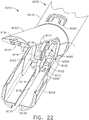
- a surgical instrument 12000 can comprise a handle 12010, a shaft 12020 extending from the handle 12010, and an end effector 12040 removably attachable to the shaft 12020, as described in greater detail further below.
- the handle 12010 can comprise a trigger 12014 which can be actuated to, one, close the end effector 12040 and, two, advance a firing member 12043 distally through the end effector 12040.
- the handle 12010 can include any suitable drive train configured to transfer and convert the rotational motion of the trigger 12014 to linear motion of a firing member 12023 extending through the shaft 12010.
- the trigger 12014 can be actuated toward a pistol grip 12012 of the handle 12010 in order to advance the firing member 12023 distally within the shaft 12020 along a longitudinal axis 12039 and, when the shaft firing member 12023 is operably coupled with the end effector firing member 12043, as discussed in greater detail further below, the distal movement of the shaft firing member 12023 can be transferred to the end effector firing member 12043.
- the end effector firing member 12043 can be configured to engage a first jaw 12040a including an anvil and/or a second jaw 12040b including a staple cartridge channel and move at least one of the first jaw 12040a and the second jaw 12040b toward the other.
- the end effector 12040 can be assembled to the shaft 12010 in a direction which is transverse to the longitudinal axis 12039.
- the end effector 12040 can be assembled to the shaft 12010 in a direction which is perpendicular to the longitudinal axis 12039, for example.
- the end effector 12040 can be moved toward the shaft 12010 such that the frame 12041 of the end effector 12040 engages and connects to the frame 12021 and such that the proximal end 12044 of the firing member 12043 engages and couples to the distal end 12024 of the firing member 12023.
- the shaft frame 12021 can include a channel 12022 defined therein which can be configured to slidably receive the shaft firing member 12023 and define the longitudinal axis 12039.
- the proximal end 12045 of the end effector frame 12041 and the distal end 12025 of the shaft frame 12021 can include co-operating dovetail features, for example, which can orient the end effector 12040 relative to the shaft 12020.
- the shaft frame 12021 can further include mounting apertures 12026 defined therein which can be configured to receive mounting projections 12046 extending from the end effector frame 12041.
- the surgical instrument 12000 can further comprise a lock collar 12030 which can be configured to lock the end effector 12040 to the shaft 12020.
- the lock collar 12030 can be moved between an unlocked position ( FIGS. 34 and 35 ) and a locked position ( FIG. 36 ).
- the end effector 12040 can be assembled to the shaft 12020.
- the lock collar 12030 can be slid over the interconnection between the end effector 12040 and the shaft 12020 to lock the end effector 12040 in place. More specifically, in at least one embodiment, the lock collar 12030 can define an inner aperture 12031 which can be configured to closely receive the outside perimeters of the end effector 12040 and the shaft 12020.
- the surgical instrument 12000 can comprise a spring or biasing member configured to bias the lock collar 12030 into its locked position. In such embodiments, a clinician can pull the lock collar 12030 proximally against the biasing force of the spring and, thereafter, release the lock collar 12030 and allow the spring to return the lock collar 12030 to its locked position.
- the surgical instrument 12000 can comprise an articulation joint 12050.
- the articulation joint 12050 in various embodiments, can be configured to permit a distal portion of the end effector 12040 to pivot about an axis defined by the articulation joint 12050.
- the end effector 12040 can comprise a proximal portion securely mounted to the shaft 12020 and the distal portion which can rotate relative to the proximal portion about the articulation joint 12050.
- the surgical instrument 12000 can comprise a lock configured to engage and disengage the distal portion of the end effector 12040.
- the end effector 12040 can include an end effector lock portion 12047 which can be pushed distally to lock the distal portion of the end effector 12040 in position and/or pulled proximally to unlock the distal portion of the end effector 12040.
- the surgical instrument 12000 can further comprise a lock actuator 12060 adjacent the handle 12010, for example, which can be pulled proximally in order to pull the end effector lock portion 12047 proximally.
- the lock actuator 12060 can be operably coupled with a lock portion 12027 extending through the shaft 12020 which is operably coupled, or operably couplable, to the end effector lock portion 12047.
- the proximal end 12048 of the end effector lock portion 12047 can be assembled to the distal end 12028 of the lock portion 12027 when the end effector 12040 is assembled to the shaft 12020.
- the end effector lock portion 12047 can be assembled to the lock portion 12027 at the same time that the end effector firing member 12043 is assembled to shaft firing member 12023.
- a staple cartridge can comprise a cartridge body including a plurality of staple cavities defined therein.
- the cartridge body can comprise a deck and a top deck surface wherein each staple cavity can define an opening in the deck surface.
- a staple can be positioned within each staple cavity such that the staples are stored within the cartridge body until they are ejected therefrom.
- the staples Prior to being ejected from the cartridge body, in various embodiments, the staples can be contained with the cartridge body such that the staples do not protrude above the deck surface. As the staples are positioned below the deck surface, in such embodiments, the possibility of the staples becoming damaged and/or prematurely contacting the targeted tissue can be reduced.
- the staples can be moved between an unfired position in which they do not protrude from the cartridge body and a fired position in which they have emerged from the cartridge body and can contact an anvil positioned opposite the staple cartridge.
- the anvil, and/or the forming pockets defined within the anvil can be positioned a predetermined distance above the deck surface such that, as the staples are being deployed from the cartridge body, the staples are deformed to a predetermined formed height.
- the thickness of the tissue captured between the anvil and the staple cartridge may vary and, as a result, thicker tissue may be captured within certain staples while thinner tissue may be captured within certain other staples.
- the clamping pressure, or force, applied to the tissue by the staples may vary from staple to staple or vary between a staple on one end of a staple row and a staple on the other end of the staple row, for example.
- the gap between the anvil and the staple cartridge deck can be controlled such that the staples apply a certain minimum clamping pressure within each staple. In some such circumstances, however, significant variation of the clamping pressure within different staples may still exist.
- an anvil such as anvil, 10060
- anvil 10060 can be moved into a closed position opposite the staple cartridge 10000.
- the anvil 10060 can position tissue against the tissue thickness compensator 10020 and, in various embodiments, compress the tissue thickness compensator 10020 against the deck surface 10011 of the support portion 10010, for example.
- the staples 10030 can be deployed, as also illustrated in FIG. 39 .
- the staple-firing sled 10050 can be moved from the proximal end 10001 of the staple cartridge 10000 toward the distal end 10002, as illustrated in FIG. 40 .
- the sled 10050 can contact the staple drivers 10040 and lift the staple drivers 10040 upwardly within the staple cavities 10012.
- the sled 10050 and the staple drivers 10040 can each comprise one or more ramps, or inclined surfaces, which can co-operate to move the staple drivers 10040 upwardly from their unfired positions.
- each staple driver 10040 can comprise at least one inclined surface and the sled 10050 can comprise one or more inclined surfaces which can be configured such that the sled inclined surfaces can slide under the driver inclined surface as the sled 10050 is advanced distally within the staple cartridge.
- the staple drivers 10040 can lift the staples 10030 upwardly such that the staples 10030 can emerge from their staple cavities 10012 through openings in the staple deck 10011 ( FIG. 41 ).
- the sled 10050 can contact a first staple 10030 and begin to lift the first staple 10030 upwardly.
- the sled 10050 can begin to lift additional staples 10030, and any other subsequent staples, in a sequential order.
- the sled 10050 can drive the staples 10030 upwardly such that the legs 10032 of the staples contact the opposing anvil, are deformed to a desired shape, and ejected therefrom the support portion 10010.
- the sled 10050 can move several staples upwardly at the same time as part of a firing sequence.
- each staple 10030 can be deformed such that a compression zone 10039 is defined therein.
- each staple 10030 can comprise a base 10031 and one or more legs 10032 extending from the base 10031 which, when deformed, can co-operatively define an area with the base 10031 within which the tissue T and the tissue thickness compensator 10020 can be captured.
- the tissue thickness compensator 10020 can apply pressure to the tissue T and, in certain circumstances, assume different compressed heights depending on the thickness of the tissue T.
- the tissue thickness compensator 10020 can resiliently fill gaps, or free spaces, present within the compression zones 10039 defined by the staples 10030.
- the staple legs 10032 of the staples 10030 can extend above the deck surface 10011 of the support portion 10010 when the staples 10030 are in their unfired positions.
- the tips of the staple legs 10032, or any other portion of the staple legs 10032 may not protrude through a top tissue-contacting surface 10021 of the tissue thickness compensator 10020 when the staples 10030 are in their unfired positions.
- the tips of the staple legs can protrude through the tissue-contacting surface.
- the tips of the staple legs 10032 can comprise sharp tips which can incise and penetrate the tissue thickness compensator 10020.
- the tissue thickness compensator 10020 can comprise a plurality of apertures which can be configured to receive the staple legs 10032 and allow the staple legs 10032 to slide relative to the tissue thickness compensator 10020.
- the support portion 10010 can further comprise a plurality of guides 10013 ( FIG. 41 ) extending from the deck surface 10011. The guides 10013 can be positioned adjacent to the staple cavity openings in the deck surface 10011 such that the staple legs 10032 can be at least partially supported by the guides 10013.
- a guide 10013 can be positioned at a proximal end and/or a distal end of a staple cavity opening.
- a first guide 10013 can be positioned at a first end of each staple cavity opening and a second guide 10013 can be positioned at a second end of each staple cavity opening such that each first guide 10013 can support a first staple leg 10032 of a staple 10030 and each second guide 10013 can support a second staple leg 10032 of the staple.
- each guide 10013 can comprise a groove or slot, such as groove 10016, for example, within which a staple leg 10032 can be slidably received.
- each guide 10013 can comprise a cleat, protrusion, and/or spike that can extend from the deck surface 10011 and can extend into the tissue thickness compensator 10020.
- the cleats, protrusions, and/or spikes can reduce relative movement between the tissue thickness compensator 10020 and the support portion 10010.
- the tips of the staple legs 10032 may be positioned within the guides 10013 and may not extend above the top surfaces of the guides 10013 when the staples 10030 are in their unfired position.
- the guides 10013 can define a guide height and the staples 10030 may not extend above this guide height when they are in their unfired position.
- a tissue thickness compensator such as tissue thickness compensator 10020, for example, can be comprised of a single sheet of material.
- a tissue thickness compensator can comprise a continuous sheet of material which can cover the entire top deck surface 10011 of the support portion 10010 or, alternatively, cover less than the entire deck surface 10011.
- the sheet of material can cover the staple cavity openings in the support portion 10010 while, in other embodiments, the sheet of material can comprise openings which can be aligned, or at least partially aligned, with the staple cavity openings.
- a tissue thickness compensator can be comprised of multiple layers of material.
- a tissue thickness compensator can comprise a compressible core and a wrap surrounding the compressible core.
- a tissue thickness compensator can comprise a wrap for releasably holding a compressible core to the support portion 10010.
- a staple cartridge can further comprise retainer clips which can be configured to inhibit the wrap, and the compressible core, from prematurely detaching from the support portion 10010.
- a tissue thickness compensator can be removably attached to the support portion 10010 by the staples 10030. More particularly, as also described above, the legs of the staples 10030 can extend into the tissue thickness compensator 10020 when the staples 10030 are in their unfired position and, as a result, releasably hold the tissue thickness compensator 10020 to the support portion 10010.
- the legs of the staples 10030 can be in contact with the sidewalls of their respective staple cavities 10012 wherein, owing to friction between the staple legs 10032 and the sidewalls, the staples 10030 and the tissue thickness compensator 10020 can be retained in position until the staples 10030 are deployed from the staple cartridge 10000.
- the tissue thickness compensator 10020 can be captured within the staples 10030 and held against the stapled tissue T.
- the support portion 10010 can be moved away from the tissue thickness compensator 10020 which has been fastened to the tissue.
- an adhesive can be utilized to removably hold the tissue thickness compensator 10020 to the support portion 10010.
- a two-part adhesive can be utilized wherein, in at least one embodiment, a first part of the adhesive can be placed on the deck surface 10011 and a second part of the adhesive can be placed on the tissue thickness compensator 10020 such that, when the tissue thickness compensator 10020 is placed against the deck surface 10011, the first part can contact the second part to active the adhesive and detachably bond the tissue thickness compensator 10020 to the support portion 10010.
- any other suitable means could be used to detachably retain the tissue thickness compensator to the support portion of a staple cartridge.
- the sled 10050 can be advanced from a proximal end to a distal end to fully deploy all of the staples 10030 contained within the staple cartridge 10000.
- the sled 10050 can be advanced distally within a longitudinal cavity within the support portion 10010 by a firing member, or knife bar, 10052 of a surgical stapler.
- the staple cartridge 10000 can be inserted into a staple cartridge channel in a jaw of the surgical stapler and the firing member 10052 can be advanced into contact with the sled 10050, as illustrated in FIG. 44 .
- the firing member 10052 can further comprise a cutting edge 10053 which can be advanced distally through a knife slot in the support portion 10010 as the staples 10030 are being fired.
- a corresponding knife slot can extend through the anvil positioned opposite the staple cartridge 10000 such that, in at least one embodiment, the cutting edge 10053 can extend between the anvil and the support portion 10010 and incise the tissue and the tissue thickness compensator positioned therebetween.
- the sled 10050 can be advanced distally by the firing member 10052 until the sled 10050 reaches the distal end of the staple cartridge 10000. At such point, the firing member 10052 can be retracted proximally. In some embodiments, the sled 10050 can be retracted proximally with the firing member 10052 but, in various embodiments, the sled 10050 can be left behind in the distal end 10002 of the staple cartridge 10000 when the firing member 10052 is retracted.
- the anvil can be re-opened, the tissue thickness compensator 10020 can be detached from the support portion 10010, and the remaining non-implanted portion of the expended staple cartridge 10000, including the support portion 10010, can be removed from the staple cartridge channel.
- a new staple cartridge 10000 can be inserted into the staple cartridge channel.
- the staple cartridge channel, the firing member 10052, and/or the staple cartridge 10000 can comprise co-operating features which can prevent the firing member 10052 from being advanced distally a second, or subsequent, time without a new, or unfired, staple cartridge 10000 positioned in the staple cartridge channel 10070.
- a support nose of the firing member10052 can be positioned on and/or over a support ledge on the sled 10050 such that the firing member 10052 is held in a sufficient upward position to prevent a lock, or beam, 10054 extending from the firing member 10052 from dropping into a lock recess defined within the staple cartridge channel.
- the lock 10054 may not abut a distal sidewall of the lock recess as the firing member 10052 is advanced.
- the firing member 10052 can be supported in its upward firing position owing to the support nose resting on the support ledge.
- the firing member 10052 can drop downwardly from its upward position as the support nose is no longer resting on the support ledge of the sled 10050.
- the surgical stapler can comprise a spring, and/or any other suitable biasing element, which can be configured to bias the firing member 10052 into its downward position.
- the firing member 10052 can't be held in its upper position by the sled 10050 as the sled 10050, at this point in the operating sequence, has been left behind at the distal end of the staple cartridge 10000.
- the lock beam 10054 will contact the sidewall 10057 of the lock recess which will prevent the firing member 10052 from being advanced distally into the staple cartridge 10000 once again.
- the new staple cartridge will have a proximally-positioned sled 10050 which can hold the firing member 10052 in its upper position and allow the firing member 10052 to be advanced distally once again.
- the sled 10050 can be configured to move the staple drivers 10040 between a first, unfired position and a second, fired position in order to eject staples 10030 from the support portion 10010.
- the staple drivers 10040 can be contained within the staple cavities 10012 after the staples 10030 have been ejected from the support portion 10010.
- the support portion 10010 can comprise one or more retention features which can be configured to block the staple drivers 10040 from being ejected from, or falling out of, the staple cavities 10012.
- the sled 10050 can be configured to eject the staple drivers 10040 from the support portion 10010 with the staples 10030.
- the staple drivers 10040 can be comprised of a bioabsorbable and/or biocompatible material, such as Ultem, for example.
- the staple drivers can be attached to the staples 10030.
- a staple driver can be molded over and/or around the base of each staple 10030 such that the driver is integrally formed with the staple.
- a compressible tissue thickness compensator can move, twist, and/or deflect relative to the underlying rigid support portion of a staple cartridge.
- the support portion, and/or any other suitable portion of the staple cartridge can comprise one or more features configured to limit relative movement between the tissue thickness compensator and the support portion.
- at least a portion of the staples 10030 can extend above the deck surface 10011 of the support portion 10010 wherein, in certain circumstances, lateral forces applied to a tissue thickness compensator can be resisted by the staples 10030 and/or the cleats 10013 extending from the support portion 10010, for example.
- the staples 10030 may tilt and/or bend within the staple cavities 10012 while resisting the lateral movement of the tissue thickness compensator wherein, in various embodiments, the staple cavities 10012 and the staples 10030 can be sized and configured to maintain the relative alignment between the legs 10032 of the staples 10030 and the forming pockets in the opposing anvil 10060 such that the staples 10000 are properly formed during the staple forming process. In various embodiments, the staples 10030 and/or the cleats 10013 can be configured to prevent or at least limit lateral distortion within the tissue thickness compensator 10020.
- the staples 10030 and/or cleats 10013 can be configured to stiffen, or limit the lateral and/or longitudinal movement of, a first, or tissue-contacting, surface of the tissue thickness compensator relative to a second, or bottom, surface.
- a staple cartridge, and/or a staple cartridge channel in which the staple cartridge is positioned can comprise at least one distortion minimizing member which can extend upwardly to limit the lateral and/or longitudinal movement, or distortion, of a tissue thickness compensator.
- a wrap at least partially surrounding a tissue thickness compensator, as discussed above, may also prevent, or at least limit, the lateral and/or longitudinal movement, or distortion, of the tissue thickness compensator.
- a staple cartridge can comprise a plurality of staple cavities each containing a staple positioned therein wherein the staple cavities can be arranged in a plurality of rows, and wherein an anvil positioned opposite the staple cartridge can comprise a plurality of forming pockets which correspond to the staple cavities in the staple cartridge.
- the anvil can comprise a plurality of forming pocket rows wherein each forming pocket can be positioned opposite a staple cavity in the staple cartridge.
- each forming pocket can comprise two forming cups configured to receive the staple legs 10032 of a staple 10030 wherein each forming cup is configured to receive a staple leg 10032 and form or curl the staple leg 10032 toward the other staple leg 10032, for example.
- an anvil can comprise an array, or grid, of forming pockets which are each configured to receive and form a staple leg.
- the array of forming pockets can comprise a quantity of forming pockets that exceeds the quantity of staples contained within the staple cartridge.
- a staple cartridge can comprise six longitudinal rows of staple cavities, for example, wherein the anvil can comprise six rows of forming pockets aligned with the six rows of staple cavities and, in addition, forming pockets positioned intermediate the rows of forming pockets.
- the anvil can comprise a first row of forming pockets which can be positioned over a first row of staple cavities, a second row of forming pockets which can be positioned over a second row of staple cavities that is adjacent to the first row of staple cavities, and, in addition, a row of forming pockets positioned intermediate the first row of forming pockets and the second row of forming pockets.
- an anvil can be moved from an open position to a closed position in order to compress tissue against the tissue thickness compensator of a staple cartridge, such as tissue thickness compensator 10020, for example.
- the tissue thickness compensator can be positioned adjacent to the support portion of the staple cartridge prior to the tissue thickness compensator being positioned relative to the tissue.
- the tissue thickness compensator 10020 can be in a position in which it abuts the support portion 10018 prior to the anvil being moved into its closed position.
- the tissue thickness compensator 10020 can be in a position in which a gap is present between the tissue thickness compensator 10020 and the support portion 10018.
- the anvil can displace the tissue and the tissue thickness compensator 10020 downwardly until the tissue thickness compensator 10020 abuts the support portion 10018 wherein, at such point, the anvil can be moved into is closed position and generate compression within the tissue.
- the surgeon can open the anvil, adjust the position of the anvil and the staple cartridge, and close the anvil once again. Owing to such positioning and re-positioning of the staple cartridge relative to the tissue, in various circumstances, the distal end of the tissue thickness compensator 10020 may become dislodged from the support portion 10010, for example.
- a staple cartridge can comprise one or more features configured to releasably retain a tissue thickness compensator to an underlying support portion of the staple cartridge
- a staple cartridge 10300 can comprise a support portion 10310, a tissue thickness compensator 10320 supported by the support portion 10310, and a distal end 10302 which includes a nose 10303 configured to releasably hold a distal end 10325 of the tissue thickness compensator 10320 in position.
- the nose 10303 can comprise a slot 10305 configured to receive the distal end 10325 of the tissue thickness compensator 10320.
- the distal end 10325 can be compressed, or wedged, within the slot 10305 such that the distal end 10325 can be held in place as the staple cartridge 10300 is positioned relative to the tissue.
- a staple cartridge 10400 can comprise a support portion, a tissue thickness compensator 10420 supported by support portion, and a distal end 10402 which includes a nose 10403 configured to releasably hold the distal end 10425 of the tissue thickness compensator 10420 in position.
- the distal end 10425 can comprise a projection extending therefrom and the nose 10403 can comprise a vertical slot 10405 configured to receive the projection of the distal end 10425.
- the distal end 10425, and/or the projection extending therefrom can be compressed, or wedged, within the slot 10405 such that the distal end 10425 can be held in place as the staple cartridge 10400 is positioned relative to the tissue.
- the tissue thickness compensator 10420 can comprise a slot, such as slot 10429, for example, which can be configured to receive at least a portion of the nose 10403 therein.
- a staple cartridge 10500 can comprise a support portion, a tissue thickness compensator 10520 supported by the support portion, and a distal end 10502 which includes a nose configured to releasably hold the distal end 10525 of the tissue thickness compensator 10520 in position.
- the nose can comprise a vertical slot 10505 configured to receive the distal end 10525 of the tissue thickness compensator 10520.
- the distal end 10525 can be compressed, or wedged, within the slot 10505 such that the distal end 10525 can be held in place as the staple cartridge 10500 is positioned relative to the tissue.
- the tissue thickness compensator 10320 can comprise a top surface 10324 which can be positioned above the top surface 10304 of the nose 10303.
- FIG. 44 Another exemplary embodiment in which the top surface of a tissue thickness compensator is positioned above the nose of the staple cartridge is illustrated in FIG. 44 , wherein the top surface 10721 of the tissue thickness compensator 10720 is positioned above the top surface 10004 of the nose 10003, for example.
- tissue can slide over the top surface 10304 of the nose 10303 and, in some circumstance, the tissue can contact the distal end 10325 of the tissue thickness compensator 10320 and can apply a force to the tissue thickness compensator 10320 tending to peel the tissue thickness compensator 10320 away from the support portion 10310. In the embodiments described herein, this peel force can be resisted by the portion of the distal end 10325 wedged within the nose 10303. In any event, once the tissue has been suitably positioned relative to the staple cartridge 13000, an anvil can be rotated into a closed position to compress the tissue and the tissue thickness compensator 10320 against the support portion 10310.
- the anvil can be rotated into a position in which the anvil contacts the top surface 10304 of the nose 10303 and, as a result, the anvil can be prevented from rotating further.
- the top surface 10324 of the tissue thickness compensator 10320 being positioned above the top surface 10304 of the nose 10303, the top surface 10324 can be pushed downwardly toward the support portion 10310 as the anvil is being closed and, in some circumstances, the top surface 10324 can be pushed below the top surface 10304 of the nose 10303, for example.
- the support portion 10310 and the nose 10303 can be moved away from the tissue thickness compensator 10320 such that the distal end 10325 of the tissue thickness compensator 10320 can slide out of the slot 10305.
- an anvil such as anvil 10060, for example, can be rotated into a closed position in which the anvil 10060 contacts the top nose surface 10004 of a staple cartridge, such as staple cartridge 10000, for example.
- a tissue thickness compensator such as tissue thickness compensator 10020, for example, is compressed will depend on, among other things, the uncompressed thickness, or height, of the tissue thickness compensator and the thickness of the tissue.
- a tissue thickness compensator 10920 can comprise a top surface which is flush, or at least substantially flush, with the top surface 10004 of the nose 10003.
- a tissue thickness compensator such as tissue thickness compensator 10820, for example, can comprise a top surface 10821 which is positioned below the top nose surface 10004 prior to the tissue thickness compensator 10820 being compressed by the tissue T and anvil 10060.
- tissue thickness compensator 10920 may undergo relatively little compression.
- the tissue thickness compensator 10820 may undergo a larger compression when the tissue T is relatively thicker.
- the tissue thickness compensator 10820 may be compressed a larger amount when it is positioned under the thicker tissue T and a lesser amount when it is positioned under the thinner tissue T, for example. In this way, as described above, the tissue thickness compensator can compensate for different tissue thicknesses.
- a surgical stapling instrument can comprise, one, a cartridge channel 16670 configured to receive a staple cartridge 16600 and, two, an anvil 16660 pivotably coupled to the cartridge channel 16670.
- the staple cartridge 16600 can comprise a support portion 16610 and a tissue thickness compensator 16620 wherein a distal end 16625 of the tissue thickness compensator 16620 can be releasably held to the support portion 16610 by a nose 16603 at the distal end 16602 of the staple cartridge 16600.
- the nose 16603 can comprise a slot 16605 and can be comprised of a flexible material.
- the nose 16603 can be flexed downwardly in order to expand the opening of slot 16605.
- the nose 16603 can comprise notches or cut-outs 16606 which can be configured to permit the nose 16603 to flex downwardly.
- the expanded opening of the slot 16605 can facilitate the insertion of the distal end 16625 of the tissue thickness compensator 16620 into the slot 16605.
- the nose 16603 can be released and, owing to the resiliency of the material comprising the nose 16603, the nose 16603 can return, or at least substantially return, to its unflexed condition and trap the distal end 16625 of the tissue thickness compensator 16620 against the deck surface 16611, as illustrated in FIG. 59 .
- the distal end 16625 can be pulled out of the slot 16605 when the support portion 16610 is moved away from the stapled tissue.
- the flexible nose 16603 can be configured to deflect as the tissue thickness compensator 16620 is detached from the support portion 16610.
- the tissue thickness compensator 16620 can comprise a top surface 16621 which is aligned, or at least substantially aligned, with a top surface 16604 of the nose 16603.
- a staple cartridge such as staple cartridge 11400, for example, can comprise a tissue thickness compensator 11420 removably attached to a support portion 11410.
- the staple cartridge 11400 can comprise one or more retainer bars 11413 which can be configured to hold the longitudinal sides of the tissue thickness compensator 11420 to the deck surface 11411.
- each retainer bar 11413 can comprise opposing arms 11418 which can define a channel 11416 therebetween.
- one of the arms 11418 can be configured to extend over the tissue thickness compensator 11420 and the other arm 11418 can be configured to extend under a lip 11419 extending from the support portion 11410.
- each retainer bar 11413 can be sized and configured to apply a compressive force to the longitudinal sides of the tissue thickness compensator 11420 prior to the staple cartridge 11400 being used.
- the staple cartridge 11400 can be positioned within a staple cartridge channel and, once the staple cartridge 11400 has been suitably positioned, an anvil, such as anvil 11460, for example, can be moved into a position in which it can compress the tissue thickness compensator 11420. Similar to the above, the thickness tissue compensator 11420, when compressed, can expand laterally, or outwardly, and, as a result, detach the retainer bars 11413 from the staple cartridge 11400.
- the closing of the anvil 11460 may not detach, or may not completely detach, the retainer bars 11413 from the staple cartridge.
- the advancement of a firing bar, described above, through the staple cartridge 11400 can deploy the staples 10030 from the support portion 11410 and, simultaneously, squeeze the anvil 11460 and the staple cartridge 11400 closer together to apply a compressive force to the tissue thickness compensator 11420 that is sufficient to cause the tissue thickness compensator 11420 to expand laterally and detach the retainer bars 11413 from the staple cartridge 11400.
- the support portion 11410 can be moved away from the implanted tissue thickness compensator 11420 and removed from the surgical site.
- a staple cartridge can comprise a plurality of fasteners configured to releasably hold a tissue thickness compensator to a support portion of the staple cartridge.
- the support portion can comprise a plurality of apertures defined in the deck surface, for example, wherein the fasteners can extend through the tissue thickness compensator and can be releasably retained in the support portion apertures.
- the fasteners can be progressively released from the support portion as the staples are progressively ejected from the support portion.
- the fasteners can be implanted with the tissue thickness compensator and, in at least one embodiment, the fasteners can be comprised of at least one bioabsorbable material, for example.
- a staple cartridge such as staple cartridge 11600, for example, can comprise a tissue thickness compensator 11620 releasably mounted to a support portion 11610 by a plurality of fasteners 11613.
- Each fastener 11613 can comprise a first end 11618 embedded within and/or otherwise engaged with the tissue thickness compensator 11620, a second end 11618 engaged with the support portion 11610, and a connector 11616 which connects the first end 11618 to the second end 11618.
- the fasteners 11613 can extend through a knife slot 11615 defined in the support portion 11610.
- a firing member 10052 can move a knife edge through the knife slot 11615 in the support portion 11610 and incise the fasteners 11613 in order to release the tissue thickness compensator 11620 from the support portion 11610.
- the firing bar 10052 can be advanced from a proximal end of the staple cartridge 11600 to a distal end of the staple cartridge 11600 in order to, one, advance the sled 10050 distally and progressively fire the staples 10030, as discussed above, and, two, progressively incise and/or break the fasteners 11613 to progressively release the tissue thickness compensator 11620 from the support portion 11610.
- the tissue thickness compensator 11620 can comprise a plurality of detachable segments which can each be held to support portion 11610 by one or more fasteners 11613, for example.
- the fasteners 11613 can assist in holding the unimplanted portion of the tissue thickness compensator 11620 to the support portion 11610 after the anvil 11660 is opened and the support portion 11610 is moved away from the tissue T, as illustrated in FIG. 131 .
- the cutting edge 10053 of the firing member 10052 can be configured to incise and/or break the fasteners 11613.
- a staple cartridge can comprise a tissue thickness compensator, such as tissue thickness compensator 15120, for example, which can comprise a plurality of portions having different thicknesses.
- the tissue thickness compensator 15120 can comprise a first, or inner, portion 15122a which can have a first thickness, second, or intermediate, portions 15122b extending from the first portion 15122b which can each have a second thickness, and third, or outer, portions 15122c extending from the second portions 15122b which can each have a third thickness.
- the third thickness can be thicker than the second thickness and the second thickness can be thicker than the first thickness, for example, although any suitable thicknesses could be utilized in various other embodiments.
- the portions 15122a-15122c of the tissue thickness compensator 15120 can comprise steps having different thickness.
- a staple cartridge can comprise several rows of staples 10030 and a plurality of staple drivers having different heights which can deform the staples 10030 to different formed heights.
- the staple cartridge can comprise first staple drivers 15140a which can drive the staples 10030 supported thereon to a first formed height, second staple drivers 15140b which can drive the staples 10030 supported thereon to a second formed height, and third staple drivers which can drive the staples 10030 supported thereon to a third formed height, wherein the first formed height can be shorter than the second formed height and the second formed height can be shorter than the third formed height, for example.
- each staple 10030 can comprise the same, or substantially the same, unformed, or unfired, height. In certain other embodiments, referring now to FIG.
- the first drivers 15140a, the second drivers 15140b, and/or the third drivers 15140c can support staples having different unformed heights.
- the first staple drivers 15140a can support staples 15130a having a first unformed height
- the second staple drivers 15140b can support staples 15130b having a second unformed height
- the third staple drivers 15140c can support staples 15130c having a third unformed height, wherein the first unformed height can be shorter than the second unformed height and the second unformed height can be shorter than the third unformed height, for example.
- the tips of the staples 15130a, 15130b, and/or 15130c can lie, or at least substantially lie, in the same plane while, in other embodiments, the tips of the staples 15130a, 15130b, and/or 15130c may not lie in same plane.
- a staple cartridge can include a tissue thickness compensator 15220 having a plurality of portions having different thickness which can be implanted against the tissue T by the staples 15130a, 15130b, and 15130c, as described above.
- a tissue thickness compensator 15220 having a plurality of portions having different thickness which can be implanted against the tissue T by the staples 15130a, 15130b, and 15130c, as described above.
- the staples 15130a, 15130b, and/or 15130c can be deformed to different formed heights wherein the first staples 15130a can be formed to a first formed height, the second staples 15130b can be formed to a second formed height, and the third staples 15130c can be formed to a third formed height, and wherein the first formed height can be shorter than the second formed height and the second formed height can be shorter than the third formed height, for example.
- the staples 15130a, 15130b, and 15130c can be formed to any suitable formed heights and/or any relative formed heights.
- a staple cartridge such as staple cartridge 10000, for example, can comprise a support portion 10010 and a tissue thickness compensator 10020 wherein a plurality of staples 10030 can be at least partially stored in the support portion 10010 and can extend into the tissue thickness compensator 10020 when the staples 10030 are in their unfired position.
- the tips of the staples 10030 do not protrude from the tissue thickness compensator 10020 when the staples 10030 are in their unfired positions.
- the tips of the staples 10030 can penetrate through the tissue thickness compensator 10020 and/or penetrate through the upper layer, or skin, 10022.
- the tips of the staples 10030 can protrude through the top surface of the tissue thickness compensator 10020 and/or skin 10022 when the staples 10030 are in their unfired position.
- the staples 10030 as they extend upwardly out of the support portion 10010 prior to being deployed, may tilt and/or deflect relative to the support portion, as also discussed above.
- a staple cartridge can comprise a tissue thickness compensator 13620 and a skin, or top layer, 13621, for example.
- one or more pledgets, or retainers, 13622 can be embedded in the skin 13621.
- each retainer 13622 can comprise one or more apertures 13629 defined therein which can be configured to receive the staple legs 13032 of staples 13030 therein when the staples 13030 are in their unfired position, as illustrated in FIG. 140 .
- a staple cartridge can comprise a tissue thickness compensator 13120 and a skin, or top layer, 13122, for example.
- the tissue thickness compensator 13120 can comprise conical bumps, projections, and/or protrusions 13128, for example, which can extend upwardly from the top surface 13121 of the tissue thickness compensator 13120.
- the projections 13128 can be configured to receive and envelop the tips of the staple legs 13032 of the staples 13030 when the staples 13030 are in their unfired position, as illustrated in FIG. 135 .
- the top layer 13122 can also comprise conical bumps, projections, and/or protrusions 13129 which can be aligned, or at least substantially aligned, with the projections 13128.
- the staple legs 10032 can penetrate the projections 13128 and 13129 and emerge from the tissue thickness compensator 13120.
- a staple cartridge can comprise a tissue thickness compensator 13520 and a skin, or top layer, 13522, for example.
- the skin 13522 can comprise conical bumps, projections, and/or protrusions 13529, for example, which can extend upwardly from the top surface 13521 of the tissue thickness compensator 13520.
- the projections 13529 can be configured to receive and envelop the tips of the staple legs 13032 of the staples 13030 when the staples 13030 are in their unfired position, as illustrated in FIG. 139 . In use, the staple legs 10032 can penetrate the projections 13529 and emerge from the skin 13522.
- a staple cartridge can comprise a tissue thickness compensator 13220 and a skin, or top layer, 13222, for example.
- the tissue thickness compensator 13220 can comprise conical dimples and/or recesses 13128, for example, which can extend downwardly into the top surface 13221 of the tissue thickness compensator 13220.
- the tips of the staple legs 13032 can extend through the recesses 13128 when the staples 13030 are in their unfired position, as illustrated in FIG. 136 .
- the top layer 13222 can also comprise conical dimples and/or recesses 13229 which can be aligned, or at least substantially aligned, with the recesses 13228.
- a staple cartridge can comprise a tissue thickness compensator 13320 and a skin, or top layer, 13322, for example.
- the skin 13320 can comprise thick portions 13329 which can extend downwardly into the top surface 13321 of the tissue thickness compensator 13320.
- the thick portions 13329 can be configured to receive at least a portion of the staple legs 13032 of the staples 13030 therein when the staples 13030 are in their unfired position, as illustrated in FIG.
- a staple cartridge can comprise a tissue thickness compensator 13420 and a skin, or top layer, 13422, for example.
- the skin 13422 can comprise thick portions 13429 which can extend upwardly from the top surface 13421 of the tissue thickness compensator 13420.
- the thick portions 13429 can be configured to receive at least a portion of the staple legs 13032 of the staples 13030 therein when the staples 13030 are in their unfired position, as illustrated in FIG. 138 .
- the thick portions 13429 can hold the staple legs 13032 in position such that the legs 13032 are aligned, or at least substantially aligned, with the staple-forming pockets of an anvil positioned opposite the tissue thickness compensator 13420.
- a staple cartridge can comprise a tissue thickness compensator 13720 and a skin, or top layer, 13721, for example.
- the tissue thickness compensator 13720 can comprise pyramidal and/or stepped bumps, projections, and/or protrusions 13728, for example, which can extend upwardly from the top surface 13721 of the tissue thickness compensator 13720.
- the projections 13728 can be configured to receive and envelop the tips of the staple legs 13032 of the staples 13030 when the staples 13030 are in their unfired position, as illustrated in FIG. 142 .
- the top layer 13721 can comprise pyramidal and/or stepped bumps, projections, and/or protrusions 13729 which can be aligned, or at least substantially aligned, with the projections 13728.
- the skin 13721 can further comprise one or more teeth 13727 extending upwardly from the projections 13729 which can be configured to engage tissue positioned against the top layer 13721 and prevent, or at least limit, relative lateral and/or longitudinal movement between the tissue, the top layer 13721, and/or the tips of the staple legs 13032.
- the staple legs 13032 can penetrate the projections 13728 and 13729 and emerge from the tissue thickness compensator 13720 when the staples 13030 are moved from their unfired positions to their fired positions.
- a staple cartridge can comprise a tissue thickness compensator 13820 and a skin, or top layer, 13821, for example.
- the tissue thickness compensator 13820 can comprise pyramidal and/or stepped bumps, projections, and/or protrusions 13828, for example, which can extend upwardly from the top surface 13821 of the tissue thickness compensator 13820.
- the projections 13828 can be configured to receive and envelop the tips of the staple legs 13032 of the staples 13030 when the staples 13030 are in their unfired position, as illustrated in FIG. 144 .
- the top layer 13821 can comprise pyramidal and/or stepped bumps, projections, and/or protrusions 13829 which can be aligned, or at least substantially aligned, with the projections 13828.
- the top layer 13821 can further comprise one or more teeth 13827 extending downwardly into the tissue thickness compensator 13820 which can be configured to prevent, or at least limit, relative lateral and/or longitudinal movement between the top layer 13821 and the tissue thickness compensator 13820, for example.
- the staple legs 10032 can penetrate the projections 13828 and 13829 and emerge from the tissue thickness compensator 13820 when the staples 13030 are moved from their unfired positions and their fired positions.
- a staple cartridge can comprise a tissue thickness compensator, such as tissue thickness compensator 13920, for example, which can include ridges 13923 and valleys 13924 defined therein wherein, in at least one embodiment, the valleys 13924 can be defined between the ridges 13923.
- tissue thickness compensator 13920 can include ridges 13923 and valleys 13924 defined therein wherein, in at least one embodiment, the valleys 13924 can be defined between the ridges 13923.
- each ridge 13923 can comprise the same height, substantially the same height, or different heights.
- each valley 13924 can comprise the same depth, substantially the same depth, or different depths.
- a plurality of staples 13030 can be at least partially stored within the tissue thickness compensator 13920 such that the tips of the staples 13030 can be positioned within the ridges 13923.
- the staple legs 13032 of the staples 13030 may not protrude from the tissue thickness compensator 13920 and/or a skin, or top layer, 13921 attached to the tissue thickness compensator 13920, for example, when the staples 13030 are stored in their unfired position.
- the ridges 13923 and/or the valleys 13924 can extend laterally across the staple cartridge.
- the staple cartridge can comprise a longitudinal knife slot wherein the ridges 13923 and the valleys 13924 can extend in a direction which is transverse and/or perpendicular to the knife slot.
- a tissue thickness compensator and/or a skin covering a tissue thickness compensator, can comprise longitudinal ridges and/or valleys.
- a tissue thickness compensator can comprise a top surface defined by ridges 14023 and valleys 14024, wherein the valleys 14024 can be defined between the ridges 14023, for example.
- the tissue thickness compensator can comprise a skin 14021 which can include a plurality of apertures 14029 defined therein which can each be configured to receive a staple leg 13032.
- the apertures 14029 can be defined in the ridges 14023 wherein the tips of the staple legs 13032 may be positioned below the peaks 14028 of the ridges 14029, positioned flush with the peaks 14028, and/or positioned above the peaks 14028.
- the apertures 14029 can be defined in the valleys 14024, for example.
- each aperture can be surrounded, or at least partially surrounded, by an embossment, for example, which can strengthen the skin and/or tissue thickness compensator surrounding the apertures.
- the skin 14021 can be attached to a tissue thickness compensator in any suitable manner, including using at least one adhesive, for example.
- a disposable loading unit 15900 can comprise an anvil 15960 and a staple cartridge channel 15970 wherein the staple cartridge channel 15970 can rotate relative to the anvil 15960.
- the anvil 15960 may not be able to rotate.
- tissue can be positioned between the anvil 15960 and the staple cartridge channel 15970 and, thereafter, the staple cartridge channel 15970 can be rotated toward the tissue to clamp the tissue against the anvil.
- the disposable loading unit 15900 can further comprise a tissue thickness compensator 15920 which can be configured to contact the tissue.
- a disposable loading unit 12900 can comprise a loading assembly including a bottom portion 12922 which can be removably attached to the support portion 12610, a top portion 12990 which can be removably attached to the anvil 12560, and a flexible joint 12991 connecting the bottom portion 12922 and the top portion 12990.
- a longitudinal retention rail 12825 can extend downwardly from the bottom portion 12922 and into the knife slot 12615 defined in the support portion 12610 such that the bottom portion 12922 can be releasably retained to the support portion 12610.
- a longitudinal retention rail 12995 can extend upwardly from the top portion 12990 into a knife slot defined in the anvil 12560 such that the top portion 12990 can be releasably retained to the anvil 12560. As illustrated in FIGS.
- a tissue thickness compensator 12620 can be mounted to the bottom portion 12922 of the loading assembly wherein, in order to position the tissue thickness compensator 12620 relative to the support portion 12610, a clinician could flex the top portion 12990 and the bottom portion 12922 toward one another, position the loading assembly between the anvil 12560 and the support portion 12610, and release the flexed loading assembly such that it can resiliently expand and bias the top portion 12990 against the anvil 12560 and the bottom portion 12922 against the support portion 12610.
- a staple cartridge such as staple cartridge 14900, for example, can comprise a support portion 14910 and, in addition, a tissue thickness compensator 14920 positioned against the support portion 14910.
- the support portion 14910 can comprise staple drivers which can be lifted upwardly by a staple-deploying sled in order to lift staples, such as staples 10030, for example, at least partially positioned within the support portion 14910 toward an anvil, such as anvil 10060, for example, positioned opposite the staple cartridge 14900.
- the support portion 14910 can comprise six rows of staple cavities, such as two outer rows of staple cavities, two inner rows of staple cavities, and two intermediate rows of staple cavities positioned intermediate the inner rows and the outer rows, for example, wherein the anvil 10060 can comprise six rows of forming pockets 10062 aligned, or at least substantially aligned, with the staple cavities.
- the inner rows of staple cavities can include staple drivers 14940a positioned therein, the intermediate rows of staple cavities can include staple drivers 14940b positioned therein, and the outer rows of staple cavities can include staple drivers 14940c positioned therein, wherein each of the staple drivers 14940a can include a cradle 14949a configured to support a staple 10030, wherein each of the staple drivers 14940b can include a cradle 14949b configured to support a staple 10030, and wherein each of the staple drivers 14940c can include a cradle 14949c configured to support a staple 10030.
- the cradles 14949a of the staple drivers 14940a can be positioned closer to the anvil 10060 than the cradles 14949b of the staple drivers 14940b and the cradles 14949c of the staple drivers 14940c.
- a first forming distance can be defined between the cradles 14949a and the forming pockets 10062 positioned over the cradles 14949a
- a second forming distance can be defined between the cradles 14949b and the forming pockets 10062 positioned over the cradles 14949b
- a third forming distance can be defined between the cradles 14949c and the forming pockets 10062 positioned over the cradles 14949c, wherein, in various embodiments, the first forming distance can be shorter than the second forming distance and the second forming distance can be shorter than the third forming distance, for example.
- each staple driver 14940a-14940c can be moved upwardly an equal, or an at least substantially equal, distance toward the anvil 10060 by the staple-deploying sled such that the first drivers 14940a drive their respective staples 10030 to a first formed height, the second drivers 14940b drive their respective staples 10030 to a second formed height, and the third drivers 14940c drive their respective staples 10030 to a third formed height, wherein the first formed height can be shorter than the second formed height and the second formed height can be shorter than the third formed height, for example.
- first staple drivers 14940a are displaced upwardly a first distance
- second staple drivers 14940b are displaced upwardly a second distance
- third staple drivers 14940c are displaced upwardly a third distance, wherein one or more of the first distance, the second distance, and the third distance can be different.
- the deck surface 14911 of the support portion 14910 can vary in height with respect to the tissue-contacting surface 10061 of the anvil 10060. In certain embodiments, this height variation can occur laterally and, in at least one embodiment, the height of the deck surface 14911 surrounding the inner rows of staple cavities can be higher than the deck surface 14911 surrounding the outer rows of staple cavities, for example. In various embodiments, the bottom surface 14922 of the tissue thickness compensator 14920 can be configured to parallel, or at least substantially parallel, the deck surface 14911 of the support portion 14910.
- the tissue thickness compensator 14920 can also vary in thickness wherein, in at least one embodiment, the top, or tissue-contacting, surface 14921 of the tissue thickness compensator 14920 can slope inwardly from the outside or lateral edges thereof. In at least one such embodiment, as a result of the above, the tissue thickness compensator 14920 can be thinner in a region positioned over the inner rows of staple cavities and thicker in a region positioned over the outer rows of staple cavities, for example. In various embodiments, referring now to FIG.
- the deck surface of a support portion 15010 can comprise a stepped deck surface, for example, wherein the highest steps of the stepped surface can surround the inner rows of staple cavities and the lowest steps of the stepped surface can surround the outer rows of staple cavities, for example.
- steps having an intermediate height can surround the intermediate rows of staple cavities.
- a tissue thickness compensator such as tissue thickness compensator 15020, for example, can comprise a bottom surface which can parallel and abut the deck surface of the support portion 15010.
- the top, or tissue-contacting, surface 15021 of the tissue thickness compensator can comprise an arcuate, parabolic, and/or curved surface, for example, which, in at least one such embodiment, can extend from a first lateral side of the tissue thickness compensator 15020 to a second lateral side of the tissue thickness compensator 15020 with an apex aligned, or at least substantially aligned, with the center of the staple cartridge 15000, for example.
- a staple-firing sled 10050 of a staple cartridge 10000 can be moved from a proximal end of the staple cartridge 10000 toward a distal end 10002 of the staple cartridge, as illustrated in FIGS. 161 and 162 , by a firing member, illustrated elsewhere. As the sled 10050 is advanced, the sled 10050 can contact the staple drivers 10040 and lift the staple drivers 10040 upwardly within the staple cavities 10012 defined in a cartridge body 10010 of the staple cartridge 10000.
- the sled 10050 and the staple drivers 10040 can each comprise one or more ramps, or inclined surfaces, which can co-operate to move the staple drivers 10040, and the staples supported thereon, upwardly from their unfired positions.
- the staple cartridge 10000 can further comprise a pan 10027, for example, which can at least partially surround the bottom of the cartridge body 10010 and at least partially contain the staple drivers 10040 within the cartridge body 10010.
- the cartridge body 10010 can further comprise a longitudinal slot 10016 defined therein which can be configured to at least partially receive the firing member as it passes through the staple cartridge 10000.
- the staples contained within the staple cartridge body 10010 can be fired sequentially between a proximal end 10001 and a distal end 10002 of the staple cartridge 10000.
- the staple cartridge 10000 can comprise staple drivers 10040a, 10040b, and 10040c, for example, which can fire the staples in a predetermined manner.
- the staple cartridge 10000 can comprise a proximal driver 10040c positioned on a first side of the longitudinal slot 10016 and a second proximal driver 10040c positioned on a second, or opposite, side of the slot 10016.
- Each driver 10040c can be configured to fire two staples, i.e., the two proximal-most staples, simultaneously.
- Such staples are positioned in the staple cavities designated 10012c.
- staple cavities 10012c can comprise a distal staple cavity designated 10013c and a proximal staple cavity 10014c.
- the reader will appreciate that the staple cavity 10013c is positioned in a different staple row than the staple cavity 10014c.
- the staple cavities 10013c and 10014c may be located in the two innermost rows of staples with the third, outermost, staple row not having a staple which is fired by a driver 10040c.
- the staple cartridge 10000 can comprise an intermediate driver 10040b positioned on a first side of the longitudinal slot 10016 and a second intermediate driver 10040b positioned on a second, or opposite, side of the slot 10016.
- Each driver 10040b can be configured to fire three staples simultaneously.
- Such staples are positioned in the staple cavities designated 10012b.
- such staple cavities 10012b can comprise a distal staple cavity designated 10013b, an intermediate staple cavity 10014b, and a distal staple cavity 10015b.
- the staple cavities 10013b, 10014b, and 10015b are all positioned in different staple rows.
- the staple cartridge 10000 can comprise a distal driver 10040a positioned on a first side of the longitudinal slot 10015 and a second distal driver 10040a positioned on a second, or opposite, side of the slot 10015.
- Each driver 10040a can be configured to fire four staples simultaneously.
- Such staples are positioned in the staple cavities designated 10012a.
- such staple cavities 10012a can comprise two distal staple cavities designated 10013a, an intermediate staple cavity 10014a, and a distal staple cavity 10015a.
- the staple cavities 10013a, 10014a, and 10015a are all positioned in an array extending across all three staple rows on a side of the longitudinal slot 10016.
- the distal-most staples positioned within the distal-most cavities 10013a within the cartridge body 10010 are positioned in the inner and outer staple rows and extend distally with respect to the distal-most staple cavity 10014a in the intermediate row positioned between the inner row and outer row of staple cavities. While only a few staple drivers 10040a, 10040b, and 10040c are discussed above, the staple cartridge 10000 can comprise any suitable number of staple drivers to eject the staples from the staple cavities. Such staple drivers can eject two, three, four, and/or more staples simultaneously. With particular reference to FIG.
- a staple cartridge can comprise one or more staple drivers 41040a, for example, configured to support two staples thereon, one or more drivers 41040b, for example, configured to support three staples thereon, and/or one or more staple drivers 41040c configured to support four staples thereon.
- the last, or distal-most, drivers contained within a cartridge can comprise drivers 41040c which can include two distal support cradles 41041c which can hold the last staples in a staple line.
- the drivers 41040a-c support staples in six staple lines and drivers 41040c support the last staples in four of those lines.
- Such staples can be aligned, or at least substantially aligned, along an axis which is perpendicular to a cut path which extends along a longitudinal axis.
- Such staples owing to their arrangement, can provide various hemostatic advantages.
- the last staples in the other two staple lines can be supported by cradles 41041b.
- a staple cartridge for a surgical stapler can include a layer, such as a tissue thickness compensator and/or a buttress material, for example, arranged on a staple deck of a staple cartridge.
- a layer such as a tissue thickness compensator and/or a buttress material, for example, arranged on a staple deck of a staple cartridge.
- the layer and patient tissue can be captured by staples when the staples are fired. Then, the layer can be separated from the surgical stapler and can remain in the patient when the stapler is removed from the patient.
- a distal end of the layer can be attached to the staple cartridge to stabilize the layer relative to the staple cartridge while the staple cartridge and the layer are being positioned relative to patient tissue.
- the staple cartridge can include a distally-arranged cutting blade that cuts the layer free from the distal end that is attached to the staple cartridge.
- FIGS. 81A-83 illustrate a staple cartridge assembly 2300 that includes a staple cartridge 2330 and a distal cutting blade 2324 arranged in a distal cavity 2332 of the staple cartridge 2330. As described in greater detail below, the distal cutting blade 2324 can be moved from an undeployed position within the distal cavity 2332 to a deployed positioned in which the cutting blade 2324 extends out of the distal cavity 2332 to sever a distal end portion 2316 of a layer 2306 arranged on the staple cartridge.
- the distal portion 2316 of the layer 2306 can be attached to the staple cartridge 2300 by being captured between the staple cartridge 2300 and a panel 2310 extending proximally from a nose 2308 of the staple cartridge assembly 2300.
- the layer 2306 can be captured by being compressed between the staple cartridge 2330 and the panel 2310.
- a gap between the staple cartridge 2330 and the panel 2310 can be smaller than a thickness of the distal portion 2316 of the layer 2306 positioned in the gap so that the distal portion 2316 is compressed between the staple cartridge 2330 and the panel 2310.
- the distal portion 2316 of the layer 2306 can include one or more apertures 2320.
- One or more pegs 2318 can extend from the panel 2308 and pass through the apertures 2320 to capture the distal portion 2316 of the layer 2306.
- the distal portion 2316 of the layer 2306 can be attached to the staple cartridge 2330 by adhesives, welding, and/or heat staking, for example.
- the distal cutting blade 2324 that severs the distal portion 2316 of the layer 2306 from the remainder of the layer 2306 can be arranged in a distal cavity 2332 of the staple cartridge 2330.
- the distal cavity 2332 and the distal cutting blade 2324 can be positioned such that the distal cutting blade 2324 can sever the distal portion 2316 of the layer 2306 at a proximal location relative to a location where the distal portion 2316 is attached to the staple cartridge 2330.
- the distal cutting blade 2324 can sever the distal portion 2316 of the layer 2306 at a proximal location relative to the pegs 2318 and apertures 2320 that attach the distal portion 2316 to the staple cartridge 2330. As a result, when the distal cutting blade 2324 severs the distal portion 2316 of the layer 2306, the remainder of the layer 2306 can be released from the staple cartridge.
- the distal cutting blade 2324 can include a cam 2322 that can push the distal cutting blade 2324 out of the distal cavity 2332.
- the cam 2322 can engage rails and/or channels 2334 in the distal cavity 2332 that can constrain the movement of the cam 2322 and the distal cutting blade 2324 to a particular direction as the blade 2324 extends out of the distal cavity 2332.
- the rails and/or channels 2334 are illustrated in FIGS. 82 and 83 as being perpendicular to the staple deck 2302 of the staple cartridge 2330. In such an arrangement, when moved from an undeployed position (shown in FIG. 82 ) to a deployed position (shown in FIG.
- the distal cutting blade 2324 can extend from the distal cavity 2332 in a direction that is perpendicular to the staple deck 2302 of the staple cartridge 2330.
- the rails and/or channels 2334 can be arranged at any suitable angle relative to the staple deck 2302 of the staple cartridge 2330.
- the rails or channels 2334 can be arranged at a 30° angle relative to the staple deck 2302 of the staple cartridge 2330 such that the distal cutting blade 2324 extends out of the distal cavity 2322 partially in a distal direction that is 30° from perpendicular relative to the staple deck 2302 of the staple cartridge 2330.
- the cam 2322 can be pushed by a firing member 2326.
- the firing member 2326 can be arranged in a slot in the staple cartridge 2330, such as the knife slot 2304, for example.
- the firing member 2326 can include cam surfaces 2328 and 2329 that can engage the cam 2322 to displace the cam 2322 and the distal cutting blade 2324 towards the layer 2306.
- the firing member 2326 can move distally relative to the cam 2322 and the distal cutting blade 2324 from an unactuated position to an actuated position to deploy the cutting blade 2324 and sever the distal portion 2316 of the layer 2306.
- FIG. 82 illustrates the firing member 2326 in an unactuated position in which the cam surfaces 2328 and 2329 have not engaged the cam 2322.
- one or both of the surfaces 2328 and 2329 of the firing member 2326 can be in contact the cam in an unactuated position so long as the distal cutting blade 2324 is not pushed out of the distal cavity 2332.
- the cam surfaces 2328 of the firing member 2326 engage the cam 2322 to progressively push the cam 2322 and the distal cutting blade 2324 to a deployed position such that the distal cutting blade severs the distal portion 2316 of the layer 2306.
- the cam 2322 can engage rails and/or channels 2334 in the distal cavity 2332.
- the rails and/or channels 2334 can be arranged at an angle relative to the staple deck 2302 of the staple cartridge 2330.
- the rails and/or channels 2334 can be arranged at an angle such that the cam 2322 and the distal cutting blade 2324 move distally as the blade 2324 deploys from the distal cavity.
- arranging the rails at such an angle can reduce the amount of force required to actuate the firing member 2326 by aligning a component of the movement of the cam 2322 and the blade 2324 along a longitudinal axis along which the firing member 2326 moves.
- Arranging the rails at such an angle can also reduce the likelihood of binding between the cam 2322 and the firing member 2326 and/or between the cam 2322 and the rails and/or channels 2324 in the distal cavity 2332.
- the firing member 2326 can be moved distally from an unactuated position to an actuated position by the cutting blade 2312 and/or a staple driver 2340.
- the firing member 2326 can be integral with the tissue-cutting blade 2312 and/or the staple driver 2340 such that the firing member 2326 travels through the staple cartridge 2330 and along a longitudinal axis of the staple cartridge 2330 with the tissue cutting blade 2312 and/or the staple driver 2340.
- the firing member 2326 can be separate from the tissue-cutting blade 2312 and/or the staple driver 2340. In such embodiments, the tissue-cutting blade 2312 and/or the staple driver 2340 can push the firing member 2326 through the staple cartridge 2330.
- the firing member 2326 can be positioned at a distal end of the staple cartridge 2330 in an unactuated position, as illustrated in FIG. 82 .
- the cutting blade 2312 and/or the staple driver 2340 can travel through the staple cartridge 2330 and then push the firing member 2326 into the actuated position illustrated in FIG. 83 as the cutting blade 2312 and/or the staple driver 2340 reach the distal end of the staple cartridge 2330.
- motion of the tissue-cutting blade 2312 and/or the staple driver 2340 in a direction along a longitudinal axis of the staple cartridge 2330 can cause the distal cutting blade 2324 to deploy in a direction different from the tissue-cutting blade and/or the staple driver 2340.
- the distal cutting blade 2324 is not deployed to sever the distal portion 2316 of the layer 2306 until the firing stroke of the tissue cutting blade 2312 and/or the staple driver 2340 have been completed or are almost completed.
- the distal portion 2316 of the layer 2306 can remain attached to the staple cartridge 2330, thereby stabilizing the layer 2306 relative to the staple cartridge 2330, until most or all of the staples have been fired by the staple driver 2340 and/or until patient tissue and the layer 2306 have been severed by the tissue cutting blade 2312.
- the distal cutting blade 2324 can be deployed to sever the distal portion 2316 of the layer 2306 before the tissue cutting blade 2312 and/or the staple driver 2340 have begun their firing stroke.
- the firing member 2326 can be moved from the unactuated position illustrated in FIG. 82 to the actuated position illustrated in FIG. 83 by a first actuation of a firing trigger of a surgical stapler.
- a subsequent actuation of the firing trigger can move the tissue cutting blade 2312 and/or the staple driver 2340.
- the distal portion 2316 of the layer 2306 can be detached from the staple cartridge 2330 before the tissue cutting blade 2312 severs patient tissue and/or before the staples capture the layer 2306 and patient tissue.
- the firing member 2326 can be actuated by a first trigger of the surgical instrument and the tissue-cutting blade 2312 and/or the staple driver 2340 can be actuated by a second trigger.
- the nose 2308 of the staple cartridge assembly 2300 can include a panel 2310 that extends proximally from the nose 2308 and that at least partially covers the distal portion 2316 of the layer 2306.
- the panel 2310 can include an inward-facing surface 2309 that can face the distal portion 2316 of the layer 2306.
- the inward-facing surface 2309 of the panel 2310 can support the distal portion 2316 of the layer 2306 as the distal cutting blade 2324 severs the distal portion 2316.
- the distal cutting blade 2324 can eventually make contact with the inward-facing surface 2309, thereby completely severing the distal portion 2316 of the layer 2306 from the remainder of the layer 2306.
- the panel 2310 can also protect patient tissue from the distal cutting blade 2324.
- unaffected patient tissue that is not severed by the tissue cutting blade 2312 and/or stapled by staples from the staple cartridge 2330 can pass over an outward-facing surface 2311 of the panel 2310.
- the panel 2310 can shield the unaffected tissue from the distal cutting blade 2324.
- the panel 2310 can be positioned between the distal cutting blade 2324 extending out of the distal cavity 2332 and patient tissue proximate to the outward-facing surface 2311 of the panel 2310, such that the patient tissue is not exposed to the distal cutting blade 2324.
- a staple cartridge 20000 can comprise a cartridge body 20010 and a tissue thickness compensator 20020 releasably attached thereto.
- the staple cartridge 20000 can comprise any suitable arrangement of staples, staple cavities, and/or staple drivers which are fired by a sled, or firing member, passing distally through the staple cartridge 20000 to capture at least a portion of the tissue thickness compensator 20020 and at least a portion of the patient tissue within the staples, as described elsewhere herein.
- Such discussion of the staples, staple cavities, and staple drivers is not repeated here for the sake of brevity to the reader. Referring primarily now to FIGS.
- the staple cartridge 20000 can include a sled 20060 which is advanced distally by a firing member 20050.
- the sled 20060 can be configured to release the tissue thickness compensator 20020 from the cartridge body 20010, as illustrated in FIGS. 78 and 79 .
- the distal end 20022 of the tissue thickness compensator 20020 can be releasably retained to the distal end of the cartridge body 20010 by a flexible clamp 20013 and a retention pin 20072 wherein the sled 20060 can defeat, or withdraw, the retention pin 20072.
- the flexible clamp 20013 can be configured to securely hold the tissue thickness compensator 20020 against the deck 20015 of the cartridge body 20010. In such circumstances, the flexible clamp 20013 can provide a sufficient clamping force to the tissue thickness compensator 20020 in order to hold the tissue thickness compensator 20020 in place.
- the retention pin 20072 may also securely hold the tissue thickness compensator 20020 to the cartridge body 20010.
- the distal end 20022 of the tissue thickness compensator 20020 can comprise an aperture 20023 defined therein which can be configured to receive the retention pin 20072 and, owing to the interaction between the retention pin 20072 and the sidewalls of the aperture 20023, the retention pin 20072 can prevent the tissue thickness compensator 20020 from sliding out between the clamp 20013 and the cartridge deck 20015.
- the retention pin 20072 and the clamp 20013 can co-operatively confine the movement of the tissue thickness compensator 20020 and, in various circumstances, the top of the retention pin 20072 can abut or can be positioned closely adjacent to the clamp 20013.
- the retention pin 20072 can be lowered by the sled 20060, as illustrated in FIGS. 78 and 79 . More specifically, the retention pin 20072 can extend from a cam 20070 wherein the cam 20070 can rest or sit upon a resilient member, or spring, 20012 extending from a pan 20011 attached to the cartridge body 20010 and, when the sled 20060 engages the cam 20070, the sled 20060 can push the cam 20070 and the retention pin 20072 downwardly thereby compressing the spring 20012.
- the cartridge body 20010 can include guides 20018 defined therein which confine the movement of the cam 20070 along a substantially vertical path, i.e., a path perpendicular to cartridge deck 20015.
- the sled 20060 can include a cam actuator 20062 which extends distally with respect to the staple driver lift surfaces 20063. Once the pin 20072 has been sufficiently lowered, the tissue thickness compensator 20020 can slide relative to cartridge deck 20015 and slip out of the clamp 20013. In various circumstances, the pin 20072 can be lowered a sufficient amount while still at least partially protruding from the cartridge deck 20015. In other circumstances, the pin 20072 can be lowered beneath the cartridge deck 20015. In either event, the cam actuator 20062 and staple driver lift surfaces 20063 of the sled 20060 can be configured such that the retention pin 20072 is sufficiently lowered at the same time that the last, or distal-most, staple is fired by the sled 20060.
- the cam actuator 20062 and staple driver lift surfaces 20063 of the sled 20060 can be configured such that the retention pin 20072 is sufficiently lowered before the last, or distal-most, staple is fired by the sled 20060.
- the cam actuator 20062 and staple driver lift surfaces 20063 of the sled 20060 can be configured such that the retention pin 20072 is sufficiently lowered after the last, or distal-most, staple is fired by the sled 20060.
- cam 20070 is described herein as having one retention pin 20072, a plurality of retention pins 20072 can extend from the cam 20070 which can each be configured to releasably retain the tissue thickness compensator 20020 to the cartridge body 20010.
- the tissue thickness compensator 20020 can include a suitable number of apertures 20023 configured to receive the retention pins 20072.
- a cartridge 21000 can comprise a cartridge body 21010, a tissue thickness compensator 21020 releasably secured to the cartridge body 21010, and a sled 21060 which can be configured to release the tissue thickness compensator 21020 from the cartridge body 21010.
- the sled 21060 can comprise staple driver lift surfaces 21063 which are configured to lift staple drivers, and staples supported thereon, toward an anvil positioned opposite the tissue thickness compensator 21020.
- the sled 21060 can further comprise a cam actuator 21062 which can be configured to deactivate a clamp 21013 holding a distal end 21022 of the tissue thickness compensator 21020 to the deck surface 21015 of the cartridge body 21010. More specifically, the clamp 21013 can include a cam 21072 extending downwardly into the cartridge body 21010 wherein the cam 21072 can be engaged by the cam actuator 21062 as the sled 21060 is advanced distally through the staple cartridge 21000.
- the cam actuator 21062 When the cam actuator 21062 engages the cam 21072, the cam actuator 21062 can lift the cam 21072 upwardly and flex the clamp 21013 away from the distal end 21022 of the tissue thickness compensator 21020, as illustrated in FIG. 81 . At such point, the cartridge body 21010 can be moved away from the tissue thickness compensator 21020. Stated another way, by the time that the tissue thickness compensator 21020 is released from the cartridge body 21010, the tissue thickness compensator 21020 will have been implanted to the patient tissue by one or more staples wherein, after the tissue thickness compensator 21020 has been released, the cartridge body 21010 can be moved away from the implanted tissue thickness compensator 21020 and removed from the surgical site.
- the cam actuator 21062 and staple driver lift surfaces 21063 of the sled 21060 can be configured such that the cam 20072 is sufficiently raised to sufficiently reduce the clamping force applied by the clamp 21013 at the same time that the last, or distal-most, staple is fired by the sled 20060.
- the cam actuator 21062 and staple driver lift surfaces 21063 of the sled 21060 can be configured such that the cam 21072 is sufficiently raised to sufficiently reduce the clamping force applied by the clamp 21013 before the last, or distal-most, staple is fired by the sled 21060.
- the cam actuator 21062 and staple driver lift surfaces 21063 of the sled 21060 can be configured such that the cam 20072 is sufficiently raised to sufficiently reduce the clamping force applied by the clamp 21013 after the last, or distal-most, staple is fired by the sled 21060.
- the clamp 21013 is described herein as having one cam 21072 extending therefrom, a plurality of cams 21072 can extend from the clamp 21013 which can each be configured to lift the clamp 21013 and release the tissue thickness compensator 20020 from the cartridge body 20010.
- a sled, or firing member, passing through a staple cartridge can release a tissue thickness compensator from a cartridge body at the end, or near the end, of the distal movement of the sled and/or the end of the firing stroke of the firing member.
- the tissue thickness compensator can be released from the cartridge body at the same time, or nearly the same time, that all of the staples have been fired from the staple cartridge.
- the tissue thickness compensator can be released from the cartridge body at the same time, or before, the first, or proximal-most, staples have been fired from the staple cartridge.
- FIGS. 90-92 illustrate a staple cartridge 22000.
- the staple cartridge 22000 can comprise a cartridge body 22010 and a tissue thickness compensator 22020 releasably secured thereto.
- the staple cartridge 22000 can further include a staple-firing sled as described above, the sled may not release the tissue thickness compensator 22020; rather, the staple cartridge 22000 may further comprise an actuator 22011 which can be advanced distally by the firing member at the beginning of the firing stroke thereof.
- an actuator 22011 which can be advanced distally by the firing member at the beginning of the firing stroke thereof.
- the actuator 22011 can include a cam support 22012 extending therefrom which can be configured to support a cam 22070 when the actuator 22011 is in its unactuated position, as illustrated in FIG. 90 .
- the staple cartridge 22000 can further comprise a biasing member, or spring, 22074 which can be configured to hold or bias the cam 22070 against the cam support 22012 while, again, the actuator 22011 is in its unactuated position illustrated in FIG. 90 .
- a retention pin 22072 extending from the cam 22070 can be engaged with and extend through an aperture 22023 defined in a distal end 22022 of the tissue thickness compensator 22020 such that, similar to the above, the retention pin 22072, and/or the retention pin 22072 in concert with a clamp 22013 extending from the cartridge body 22010, can hold the tissue thickness compensator 22020 in position.
- the cam support 22012 can be advanced distally such that the cam support 22012 may no longer support the cam 22070.
- the spring 22074 may bias the cam 22070 downwardly such that the retention pin 22072 is biased out of engagement, or at least partially out of engagement, with the tissue thickness compensator 22020.
- the spring 22074 can bias the cam 22070 downwardly such that the retention pin 22072 is positioned below the deck 22015 of the cartridge 22010.
- the distal advancement of the actuator 22011 can release the tissue thickness compensator 22020 from the cartridge body 22010.
- the clamp 22013 may still provide a holding force to the tissue thickness compensator 22020 such that the tissue thickness compensator 22020 remains pinned against the staple deck 22015; however, the tissue thickness compensator 22020 can be slid out from underneath the clamp 22013 upon the application of a sufficient relative force between the tissue thickness compensator 22020 and the cartridge body 22010.
- the release of the tissue thickness compensator 22020 from the cartridge body 22010 can occur before, contemporaneous with, and/or immediately after the proximal-most staples are fired from the staple cartridge 22000. In such circumstances, the early release of the tissue thickness compensator 22020 may permit the tissue thickness compensator 22020 to be released from the cartridge body 22010 eventhough the staple cartridge 22000 has only been partially fired, for example.
- an end effector assembly 5000 can include a first jaw, illustrated elsewhere, and a second jaw 5002.
- the second jaw 5002 can include a cartridge assembly that includes a fastener cartridge body 5050 and a tissue thickness compensator 5058 releasably secured to the fastener cartridge body 5050.
- the fastener cartridge body 5050 can have a cartridge deck 5052 and fastener cavities 5054 defined in the cartridge deck 5052.
- the second jaw 5002 can include fasteners, such as surgical staples, for example, which can be removably positioned in the fastener cavities 5054.
- a fastener can be ejectably positioned in each fastener cavity 5054 of the cartridge body 5050.
- the cartridge body 5050 can include a slot 5056, which can extend from a proximal portion 5004 of the second jaw 5002 toward a distal portion 5006 of the second jaw 5002.
- a firing assembly 5030 can translate along the slot 5056 of the cartridge body 5050.
- the firing assembly 5030 can translate within the slot 5056 during a firing stroke, and can eject the fasteners from the fastener cavities 5054 during the firing stroke.
- the firing assembly 5030 can include a firing bar ( FIG. 84 ), a cutting edge 5036, a crossbar 5038, and a foot 5044 ( FIGS. 86 and 87 ).
- the cutting edge 5036 can cut tissue and/or cut the tissue thickness compensator 5058 as the firing assembly 5030 is fired through the second jaw 5002 during a firing stroke.
- the crossbar 5038 can hold the first jaw relative to the cartridge body 5050, and the foot 5044 can hold the firing assembly 5030 relative to the cartridge body 5050, for example.
- the crossbar 5038 and the foot 5044 can hold the cutting element 5036 perpendicular to the deck 5052 of the fastener cartridge 5050, for example.
- the firing assembly 5030 can engage a sled 5034 in the cartridge body 5050 during the firing stroke.
- the firing assembly 5030 can push the sled 5034 distally during the firing stroke to eject fasteners from the fastener cavities 5054, for example.
- the tissue thickness compensator 5058 can be releasably secured to the cartridge body 5050 by at least one connector 5080a, 5080b.
- multiple connectors 5080a, 5080b can secure the tissue thickness compensator 5058 to the cartridge body 5050.
- a proximal connector 5080a can secure the tissue thickness compensator 5058 to the cartridge body 5050 at the proximal portion 5004 of the second jaw 5002
- a distal connector 5080b can secure the tissue thickness compensator 5058 to the cartridge body 5050 at the distal portion 5006 of the second jaw 5002.
- additional connectors can secure the tissue thickness compensator 5058 to the cartridge body 5050.
- the additional connectors can be spaced along at least a portion of the length of the cartridge body 5050, and can be positioned between the proximal connector 5080a and the distal connector 5080b, for example.
- the connectors 5080a, 5080b can hold the tissue thickness compensator 5058 relative to the cartridge body 5050.
- the tissue thickness compensator 5058 can be released from the cartridge body 5050 when the connectors 5080a, 5080b are broken, cut, dislodged or otherwise overcome.
- the firing assembly 5030 can overcome the connectors 5080a, 5080b as the firing assembly 5030 translates along the slot 5056 in the fastener cartridge 5050 during a firing stroke. During such a firing stroke, the firing assembly 5030 can cut tissue clamped between the first jaw and the second jaw 5002, and can also move the fasteners from the fastener cavities 5054 into the clamped tissue.
- the firing assembly 5030 can push the sled 5034 ( FIGS. 86 and 87 ) distally during the firing stroke.
- the sled 5034 can have a camming surface or ramp 5042, which can engage drivers in the fastener cavities 5054. When the ramp 5042 engages a driver, the ramp 5042 can push the driver toward the deck 5052 to eject the fastener from the fastener cavity 5054. Further, the firing assembly 5030 can cut the tissue thickness compensator 5058 and the connectors 5080a, 5080b during the firing stroke.
- the cutting edge 5036 of the firing assembly 5030 can cut the proximal connector 5080a at or near the beginning of the firing stroke, for example, and can cut the distal connector 5080b at or near the end of the firing stroke, for example.
- the sled 5034 FIGS. 86 and 87 ) can eject the fasteners from the fastener cavities 5054 after the cutting edge 5036 cuts the proximal connector 5080a and before the cutting edge 5036 cuts the distal connector 5080b.
- the cutting edge 5036 of the firing assembly 5030 may stop before reaching the distal connector 5080b, and the tissue thickness compensator 5058 may remain secured to the cartridge body 5050 at the distal portion 5006 of the second jaw 5002.
- the tissue thickness compensator 5058 can remain secured to the cartridge body 5050 until the operator cuts or otherwise overcomes the distal connector 5080b. For example, the operator may introduce an additional surgical instrument and/or step in the surgical procedure to overcome the distal connector 5080b.
- the second jaw 5002 can overcome the connectors 5080a, 5080b at or near the beginning of the firing stroke.
- an element of the second jaw 5002 can overcome the proximal connector 5080a, the distal connector 5080b, and any additional connectors therebetween at or near the beginning of the firing stroke.
- the second jaw 5002 and/or the cartridge assembly can include an actuator 5010, which can overcome the distal connector 5080b before the fasteners are ejected from the fastener cavities.
- the actuator 5010 can overcome the distal connector 5080b and the tissue thickness compensator 5358 can be released from the cartridge body 5050 even when the firing stroke terminates prematurely, i.e., before the firing assembly 5030 reaches the distal portion 5006 of the second jaw 5002, for example.
- the actuator 5010 can include a bottom side 5016 ( FIGS. 85A-85C ) and sidewalls 5018 ( FIGS. 84 and 85D ).
- the sidewalls 5018 can extend from the bottom side 5016 and around at least a portion of the cartridge body 5050.
- the bottom side 5016 and/or the sidewalls 5018 can extend past or around the fasteners positioned in the fastener cavities 5054.
- the actuator 5010 can be moveably held relative to the cartridge body 5050.
- the actuator 5010 can move from a pre-actuated position ( FIG. 85A ) to an actuated position ( FIGS. 85B and 85D ).
- the sidewalls 5018 of the actuator 5010 can engage slits in the cartridge body 5050, such that the actuator 5010 moves in the slits to slide relative to the cartridge body 5050.
- the actuator 5010 can slide relative to the fasteners positioned in fastener cavities 5054 of the cartridge body 5050.
- the actuator 5010 can slide past and/or around the fasteners positioned in the fastener cavities 5054.
- the actuator 5010 can include a slot 5012, which can extend from the proximal portion 5004 toward the distal portion 5006 of the second jaw 5002.
- the slot 5012 in the actuator 5010 can correspond to and/or be aligned with the slot 5056 ( FIG. 84 ) in the cartridge body 5050, for example.
- the firing assembly 5030 can translate along and/or within the slot 5012 in the actuator 5010 as the firing assembly 5030 translates along and/or within the slot 5056 in the cartridge body 5050 during the firing stroke.
- the firing assembly 5030 can engage the actuator 5010 to move the actuator 5010 distally when the firing assembly 5030 is at or near the beginning of the firing stroke.
- the firing assembly 5030 can actuate the actuator 5010 at the proximal portion 5004 of the second jaw 5002.
- a distal end of the actuator 5010 can cut or otherwise overcome the distal connector 5080b, for example.
- proximal actuation of the actuator 5010 can effectuate distal release of the tissue thickness compensator 5058 from the cartridge body 5050.
- the actuator 5010 can merely shift distally to overcome the distal connector 5080b.
- the actuator 5010 can shift approximately 1 mm, for example, before overcoming the distal connector 5080b.
- the actuator 5010 can shift approximately 0.5 mm to approximately 5 mm, for example, before overcoming the distal connector 5080b.
- the actuator 5010 can move from the pre-actuated position ( FIG. 85A ) to the actuated position ( FIG. 85B ) when the firing assembly 5030 moves between an unfired position and a partially fired position during part of the firing stroke.
- the actuator 5010 can include a release stop, such as detent tabs 5022, for example.
- the progression of the firing element relative to the actuator 5010 can be paused by the detent tabs 5022.
- the detent tabs 5022 can temporarily halt the progression of the firing assembly 5030 relative to the actuator 5010.
- the detent tabs 5022 can engage the sled 5034 and/or the firing assembly 5030 to hold the firing assembly 5030 relative to the actuator 5010, such that the actuator 5010 moves therewith.
- the bottom side 5016 of the actuator 5010 can include a detent tab 5022
- the sled 5034 can include a recess or groove 5040.
- the groove 5040 can receive the tab 5022 when the sled 5034 is positioned in the proximal portion 5004 of the second jaw 5002.
- the groove 5040 can be aligned with the tab 5022 when the firing assembly 5030 moves from an unfired position to a fired position, and thus, when the actuator is pushed from a pre-actuated position ( FIG. 85A ) to an actuated positioned ( FIG. 85B ).
- at least one tab 5022 can be positioned on either side of the slot 5012 ( FIGS. 85A-85C ) in the actuator 5010, and each tab 5022 can engage the sled 5034.
- the sled 5034 can engage the detent tabs 5022 as the firing assembly 5030 and sled 5034 translate along the slot 5056 ( FIG. 84 ) during the firing stroke.
- the detent tabs 5022 can engage the sled 5034 at or near the beginning of the firing stroke.
- the detent tabs 5022 can be near the proximal end of the actuator 5010, and the sled 4034 can engage the detent tabs 5022 upon the initiation of the firing stroke.
- the actuator 5010 can be driven and/or shifted distally.
- the actuator 5010 can move distally until it reaches a hard stop 5060 defined in the cartridge body 5050, for example.
- the hard stop 5060 can be at the distal portion 5006 of the second jaw 5002, and can prevent further distal movement of the actuator 5010, for example.
- the actuator 5010 can abut the hard stop 5060 before the firing assembly 5030 ejects the fasteners from the fastener cavities 5054 of the cartridge body 5050 ( FIG. 84 ).
- the actuator 5010 can abut the hard stop 5060 as the firing assembly 5030 ejects at least one fastener from a fastener cavity 5054 and/or after the firing assembly 5030 has ejected at least one fastener from a fastener cavity 5054.
- the actuator 5010 when the actuator 5010 is pushed distally by the sled 5034 and/or the firing assembly 5030, the actuator 5010 can cut or otherwise overcome the distal connector 5080b to release the tissue thickness compensator 5058 from the cartridge body 5050 at the distal portion 5006 of the second jaw 5002.
- the actuator 5010 can include a notch 5024 for receiving and holding the distal connector 5080b. The notch 5024 can hold the distal connector 5080b as the actuator 5010 shifts distally toward the hard stop 5060. Further, the actuator 5010 can include a cutting edge 5020, for example, along the notch 5024.
- the distal connector 5080b when the actuator 5010 moves toward the hard stop 5060, the distal connector 5080b can be pushed between the hard stop 5060 and the cutting edge 5020 of the actuator 5010.
- the cutting edge 5020 can cut the distal connector 5080b when the cutting edge 5020 is pushed into and/or toward the hard stop 5060.
- the distal connector 5080b can be cut by the cutting edge 5020 of the actuator 5010 at or near the beginning of the firing stroke and before the fasteners are fired from the fastener cavities 5054 ( FIG. 84 ).
- the cutting edge 5020 can cut the distal connector 5080b as the firing assembly 5030 ejects at least one fastener from a fastener cavity 5054 and/or after the firing assembly 5030 has ejected at least one fastener from a fastener cavity 5054.
- the actuator 5010 can overcome the distal connector 5080b without cutting it. For example, the actuator 5010 can dislodge or stretch the distal connector 5080b out of position such that the distal connector 5080b no longer holds the tissue thickness compensator 5058 relative to the cartridge body 5050.
- the proximal connector 5080a can be cut by a proximal cutting edge on the actuator 5010.
- additional connectors along the length of the cartridge body 5050 can be cut or otherwise overcome by the actuator 5010 at or near the beginning of the firing stroke.
- the cutting edge 5036 of the firing assembly 5030 can cut or otherwise overcome the proximal connector 5080a and/or additional connectors.
- the cutting edge 5036 of the firing assembly 5030 can cut the proximal connector 5080a and the cutting edge 5020 of the actuator 5010 can cut the distal connector 5080b before the fasteners are ejected from the fastener cavities 5054 of the cartridge body 5050 ( FIG. 84 ).
- the sled 5034 and/or the firing assembly 5030 can be configured to overcome the detent tabs 5022 of the actuator 5010.
- the firing assembly 5030 and the sled 5034 can move relative to the actuator 5010.
- the firing assembly 5030 can push the sled 5034 distally to move the actuator 5010 distally until further distal movement of the actuator is prevented by the hard stop 5060 ( FIGS. 85A , 85C , and 85D ).
- the firing assembly 5030 can push the sled 5034 with sufficient force to deform, deflect, and/or dislodge the detent tabs 5022 from the recesses 5040 in the sled 5034.
- the tabs 5022 can each comprise a cantilever which can flex downwardly out of engagement with the groove 5040 after a sufficient longitudinal force has been applied to the sled 5034.
- the detent tabs 5022 can be sufficiently rigid to withstand the force of the firing assembly 5030 as the actuator 5010 shifts distally toward the hard stop 5060, and can be sufficiently flexible to deflect when the actuator 5010 reaches the hard stop 5060 without requiring excessive force by a motor and/or operator.
- the detent tabs 5022 can be configured to permit the firing bar 5032 to pass through the cartridge body 5050 after the force applied to detent tabs 5022 has exceeded a predetermined force.
- an end effector assembly 5100 can include a first jaw, illustrated elsewhere, and a second jaw 5102.
- the second jaw 5102 and/or a fastener cartridge assembly positionable therein can include an actuator 5110.
- the actuator 5110 can slide or shift relative to a fastener cartridge body, such as the fastener cartridge body 5050 ( FIG. 84 ), for example, of the fastener cartridge assembly.
- the actuator 5110 can include a bottom wall 5116 and sidewalls 5118, which can be positioned at least partially around the cartridge body 5050. The bottom wall 5116 and/or the sidewalls 5118 can extend past or around the fasteners positioned in the fastener cavities 5054 ( FIG.
- the actuator 5110 can include a slot 5112 extending along at least a portion of the bottom wall 5116.
- the sidewalls 5118 can include lips 5122 and/or lips 5124, which can slidably engage the cartridge body 5050.
- the lips 5122 can extend around the cartridge body 5050 and into slits in the deck 5052 ( FIG. 84 ) of the cartridge body 5050.
- the lips 5124 can extend into slits along the side of the cartridge body 5050, for example.
- the lips 5122, 5124 can slide within the slits as the actuator 5110 moves relative to the cartridge body 5050.
- the lips can constrain and/or define the relative movement between the actuator 5110 and the cartridge body 5050, for example.
- the actuator 5110 moves relative to the cartridge body 5050, the actuator 5110 can slide relative to the fasteners positioned in the fastener cavities 5054 of the cartridge body 5050.
- the actuator 5110 can slide past or around the fasteners in the fastener cavities 5054.
- the actuator 5110 can include a release stop, such as detent 5114, for example, at the proximal portion 5104 of the second jaw 5102, for example.
- the detent 5114 can include a detent arm 5120 which can operably hold a sled 5134 of the cartridge body 5050 ( FIG. 84 ).
- the sled 5134 can include a groove 5144 and the detent arm 5120 can engage the groove 5144 to retain the sled 5134 relative to the actuator 5110.
- the detent 5114 can have multiple detent arms 5120, which can be retained in grooves 5144 in the sled 5134.
- the detent arms 5120 can extend from opposite sides of the actuator 5110, for example, and the sled 5134 can be positioned intermediate the detent arms 5120, for example.
- the firing assembly 5030 can push against the sled 5134 and can shift the actuator 5110 distally while the detent arms 5120 are held in the grooves 5144 of the sled 5134 ( FIG. 29A ).
- the detent arms 5120 can be sufficiently rigid to hold the sled 5134 relative to the actuator 5110 as the actuator 5110 is pushed distally by the firing assembly 5030. Thereafter, the actuator 5110 can abut a hard stop, such as hard stop 5060 ( FIGS. 84-85B and 85D ), for example, which can prevent further distal movement of the actuator 5110.
- the firing assembly 5030 can push the sled 5134 through the detent 5114.
- the firing assembly 5030 can force the sled 5134 to overcome the detent arms 5120.
- the detent arms 5120 can be sufficiently flexible to flex out of engagement with the grooves 5144 of the sled 5134 and permit passage of the firing assembly 5030 between the detent arms 5120 and along the slot 5112 in the actuator 5110.
- the actuator 5110 can include an edge that can cut or otherwise overcome a distal connector, similar to distal connector 5080b ( FIG.
- the actuator 5110 can overcome the distal connector and/or additional connector(s) before a fastener is fired from the fastener cartridge 5050. In certain embodiments, the actuator 5110 can overcome the distal connector and/or additional connector(s) as at least one fastener is fired from a fastener cavity and/or after at least one fastener has been fired from a fastener cavity.
- an end effector assembly 5200 can include a first jaw, illustrated elsewhere, and a second jaw 5202.
- the second jaw 5202 and/or a fastener cartridge assembly can include an actuator 5210 that can slide relative to a fastener cartridge body, such as the fastener cartridge body 5050 ( FIG. 84 ), for example.
- the actuator 5210 can include a bottom wall 5216 and sidewalls. The sidewalls can be positioned at least partially around the cartridge body 5050, for example.
- the actuator 5210 can include a slot 5212 extending along at least a portion of the bottom wall 5216. Further, the actuator 5210 can be moveably held relative to the cartridge body 5050.
- the actuator 5210 can move relative to the fasteners positioned in the fastener cavities 5054 of the cartridge body 5050.
- the actuator 5210 can slide past or around the fasteners positioned in the fastener cavities 5054.
- the firing assembly 5030 can translate along and/or within the slot 5212 during a firing stroke. Similar to the actuators 5010, 5110, the actuator 5210 can include a release stop 5214. In various embodiments, the release stop 5214 can include a frangible portion 5220, which can be a bridge across the slot 5212, for example. Referring primarily to FIG. 87A , the firing assembly 5030 can abut the release stop 5214 to push the actuator 5210 distally. Thereafter, the actuator 5210 can abut a hard stop, such as hard stop 5060 ( FIGS. 84-85B and 85D ), which can prevent further distal movement of the actuator 5210. Referring primarily to FIG.
- the firing assembly 5030 can break the frangible portion 5220 of the release stop 5214 to continue moving distally along the slot 5212 during the firing stroke.
- the frangible portion 5220 can be sufficiently rigid to withstand the force of the firing assembly 5030 as the actuator 5210 shifts distally toward the hard stop 5060 ( FIG. 85D ), and can be sufficiently frangible to break when the actuator 5210 reaches the hard stop 5060 without requiring excessive force by a motor and/or operator.
- the actuator 5210 can overcome the distal connector 5080b and/or additional connector(s) before a fastener is fired from the fastener cartridge 5050.
- the actuator 5210 can overcome the distal connector and/or additional connector(s) as at least one fastener is fired from a fastener cavity and/or after at least one fastener has been fired from a fastener cavity.
- an end effector assembly 5300 can include a first jaw, illustrated elsewhere, and a second jaw 5302.
- the second jaw 5302 can include a cartridge body 5350 and a tissue thickness compensator 5358 releasably secured to the cartridge body 5350.
- the second jaw 5302 can include fasteners, such as surgical staples, for example, which can be removably positioned in fastener cavities in the cartridge body 5350.
- a fastener can be ejectably positioned in each fastener cavity.
- the cartridge body 5350 can include a slot 5356 ( FIG.
- the firing assembly 5030 can translate along the slot 5356 of the cartridge body 5350.
- the firing assembly 5030 can translate within the slot of the fastener cartridge 5350 during a firing stroke, and can eject the fasteners from the fastener cavities during the firing stroke, for example.
- the firing assembly 5030 can engage a sled 5334 ( FIG. 89 ) in the cartridge body 5350 during the firing stroke, for example, and can push the sled 5334 distally during the firing stroke, for example.
- the firing assembly 5030 and/or an actuator 5310 can release the tissue thickness compensator 5358 from the cartridge body 5350.
- the tissue thickness compensator 5358 can include a body 5360, a proximal mount 5362 extending from the body 5360, and a distal mount 5364 extending from the body 5360.
- a pin 5366 can extend through the proximal mount 5362 into an opening 5356a in the cartridge body 5350, such that the pin 5366 releasably holds the tissue thickness compensator 5358 relative to the cartridge body 5350 at the proximal portion 5304 of the second jaw 5302, for example.
- the pin 5366 can be friction fit and/or snap-fit into the opening 5356a, for example.
- the pin 5366 can be held in the opening 5456a utilizing one or more adhesives, for example. In some embodiments, at least a portion of the cartridge body 5350 and/or pin 5366 can be welded, for example.
- the tissue thickness compensator 5358 can include multiple proximal mounts 5362, which can be releasably secured to the cartridge body 5350 on either side or both sides of the slot 5356 ( FIG. 88 ) in the cartridge body 5350. In certain embodiments, the distal mount 5364 can be secured to the cartridge body 5350 at the distal portion 5306 of the second jaw 5302, for example.
- the distal mount 5364 can be secured to the cartridge body 5350 via at least one adhesive between the distal mount 5364 and the cartridge body 5350, for example. Additionally or alternatively, the distal mount 5364 can be secured to the cartridge body 5350 by at least one pin and/or other fastener, for example.
- the actuator 5310 can loop around the distal mount 5364 and can extend to the sled 5334 in the second jaw 5302.
- the actuator 5310 can comprise a cable or cord, which can extend through the cartridge body 5350 and/or through a channel 5346 defined in the second jaw 5302 and/or in the sled 5334, for example.
- distal movement of the sled 5334 can pull the actuator 5310 to break through the distal mount 5364 of the tissue thickness compensator 5358.
- the actuator 5310 can have a first end 5316 secured to the sled 5334, a second end 5318 secured within the cartridge body 5350, and a loop 5320 between the first end 5316 and the second end 5318.
- the loop 5320 can loop around the distal mount 5364, for example.
- the loop 5320 can wrap around the distal mount 5364 between the portion of the distal mount 5364 that is secured to the cartridge body 5350 and the body 5360 of the tissue thickness compensator 5358.
- the second end 5318 can be fixedly secured in the cartridge body 5350, such that when the first end 5316 moves, the loop 5320 tightens around the distal mount 5364.
- the second jaw 5302 and/or the cartridge body 5350 can include buttons, pins, and/or castors, such as a first button 5312 and a second button 5314, for example.
- the actuator 5310 can wrap around the first button 5312 and the second button 5314, for example.
- the position of the buttons 5312, 5314 and the orientation of the actuator 5310 around the buttons 5312, 5314 can cause the loop 5320 of the actuator 5310 to tighten around the distal mount 5364 when the sled 5334 and the firing assembly 5330 move distally during a firing stroke. Further, as the loop 5320 tightens around the distal mount 5364, the loop 5320 can break through the distal mount 5364 to release the body 5360 of the tissue thickness compensator 5358 from the cartridge body 5350 at the distal portion 5306 of the second jaw 5302. As such, in view of the above, the distal mount 5364 can be disengaged during the beginning of the firing stroke.
- the pin 5366 securing the proximal mount 5362 of the tissue thickness compensator 5358 to the cartridge body 5350 can be released from the opening 5356 in the cartridge body 5350.
- the pin 5366 can be released from the opening 5356.
- the pin 5366 can be sheared and/or severed by the cutting edge 5036 of the firing assembly 5030, for example, and/or can be pushed and/or driven out of the opening 5356 by an element of the firing assembly 5030.
- the tissue thickness compensator 5358 can be released from the cartridge body 5350 at or near the beginning of the firing stroke when both the proximal mount 5362 and the distal mount 5364 are released from the cartridge body 5350.
- the actuator 5310 can release the tissue thickness compensator 5358 from the cartridge body 5350 prior to the firing assembly 5030 and/or the sled 5334 ejecting the fasteners from the fastener cavities in the cartridge body 5350.
- the firing assembly 5030 and/or the sled 5334 can eject at least one fastener from a fastener cavity before and/or while the actuator 5310 releases the tissue thickness compensator 5358 from the cartridge body 5350.
- a fastener cartridge assembly can comprise a cartridge body comprising a plurality of fastener cavities and a slot.
- the fastener cartridge assembly can further comprise a plurality of fasteners, wherein each fastener is removably positioned in a fastener cavity.
- the fastener cartridge assembly can further comprise a firing element configured to move along the slot, a tissue thickness compensator releasably secured to the cartridge body, and a mount, wherein the mount secures the tissue thickness compensator to the cartridge body, and wherein the mount is positioned distal to a fastener of the plurality of fasteners.
- the fastener cartridge assembly can further comprise a cable between the firing element and the mount, wherein the cable is configured to break the mount when the firing element moves distally along the slot.
- the tissue thickness compensator can be released from the cartridge body when the cable breaks the mount.
- the cable can break the mount prior to the removal of the fasteners from the fastener cavities.
- the fastener cartridge assembly can further comprise a channel, wherein the cable extends through the channel.
- an end effector assembly 5600 can include a first jaw, illustrated elsewhere, and a second jaw 5602.
- the second jaw 5602 can include a fastener cartridge body 5650 and a tissue thickness compensator 5658 releasably secured to the second jaw 5602 and/or to the fastener cartridge body 5650.
- the fastener cartridge body 5650 and the tissue thickness compensator 5658 releasably secured thereto can comprise a fastener cartridge assembly.
- the cartridge body 5650 can have a cartridge deck 5652 and fastener cavities 5654 defined in the cartridge deck 5652.
- the second jaw 5602 can include fasteners, such as surgical staples, for example, which can be removably positioned in the fastener cavities 5654.
- fasteners such as surgical staples, for example, which can be removably positioned in each fastener cavity 5654 of the cartridge body 5650.
- the cartridge body 5650 can include a ridge 5648 extending from the cartridge deck 5652.
- the ridge 5648 can extend around at least a portion of a fastener cavity 5654, for example.
- the tip of the fastener can protrude from the fastener cavity 5654.
- the cartridge body 5650 can include a slot 5656, which can extend from a proximal portion 5604 of the second jaw 5602 toward a distal portion 5606 of the second jaw 5602.
- a firing assembly 5630 can translate along the slot 5656 of the cartridge body 5650.
- the firing assembly 5630 can translate along the slot 5656 during a firing stroke, and can eject fasteners from the fastener cavities 5654 during the firing stroke.
- the firing assembly 5630 can include a firing bar 5632, a cutting edge 5636, a crossbar 5638, and a foot 5644.
- the cutting edge 5636 can cut tissue and/or cut the tissue thickness compensator 5658 as the firing assembly 5630 is fired through the second jaw 5602 during a firing stroke.
- the crossbar 5638 can engage a slot in the anvil of the first jaw to hold the firing assembly 5630 relative to the first jaw, and the foot 5644 can engage a slot in the second jaw 5602, such as the slot 5656 in the cartridge body 5650, for example, to hold the first jaw relative to the cartridge body 5650.
- the crossbar 5638 and/or the foot 5644 can hold the cutting edge 5636 of the firing assembly 6530 perpendicular to the deck 5652 of the fastener cartridge 5650, for example.
- the firing assembly 5630 can engage a sled 5634 in the cartridge body 5650 during the firing stroke.
- the firing assembly 5630 can push the sled 5634 distally during the firing stroke to eject fasteners from the fastener cavities 5654, for example.
- the sled 5634 can have a camming surface or ramp 5642, which can engage drivers and/or fasteners in the fastener cavities 5654, for example.
- the ramp 5642 When the ramp 5642 engages a driver, the ramp 5642 can push the driver toward the deck 5652 to eject the corresponding fastener from the fastener cavity 5654. Further, in various embodiments, the firing assembly 5630 can cut the tissue thickness compensator 5658 during the firing stroke.
- the tissue thickness compensator 5658 can include a cartridge contacting surface 5662 ( FIG. 93A ) and a tissue contacting surface 5664 ( FIG. 93B ).
- the cartridge contacting surface 5662 can be positioned against the cartridge deck 5652 when the tissue thickness compensator 5658 is secured to the cartridge body 5650 ( FIG. 93B ), for example.
- the tissue contacting surface 5664 can be positioned against tissue when tissue is clamped between the first jaw and the second jaw 5602, for example.
- the tissue thickness compensator 5658 can include a mount 5660.
- the mount 5660 can be a rectangular or triangular flap, for example, that can extend from the tissue thickness compensator 5658. Further, the mount 5660 can be a cutout portion of the tissue thickness compensator 5658, such that a space 5666 is left in the tissue thickness compensator 5658 that corresponds to the shape of the mount 5660.
- the mount 5660 can be aligned with the slot 5656 of the cartridge body 5650 when the tissue thickness compensator 5658 is positioned relative to the cartridge body 5650, for example. Further, the mount 5660 can extend into the slot 5656 when the cartridge contacting surface 5662 of the tissue thickness compensator 5658 is positioned adjacent to the deck 5652 of the cartridge body 5650.
- the mount 5660 can be friction fit into the slot 5656 when the tissue thickness compensator 5658 is secured to the cartridge body 5650.
- the mount 5660 can hold at least a portion of the tissue thickness compensator 5658 relative to the cartridge body 5650.
- the cartridge contacting surface 5662 can be positioned against the deck 5652 of the cartridge body 5650.
- the tissue thickness compensator 5658 can include a plurality of mounts 5660, which can be aligned with the slot 5656 of the cartridge body 5650.
- at least one mount 5660 can be positioned in the proximal portion 5604 of the second jaw 5602, and at least one mount 5660 can be positioned in the distal portion 5606 of the second jaw 5602.
- the mounts 5660 can be spaced along at least a portion of the length of the tissue thickness compensator 5658.
- the slot 5656 can be a longitudinal slot that extends from the proximal portion 5604 to the distal portion 5606 of the second jaw 5602.
- the mounts 5660 can be friction fit into the longitudinal slot 5656, for example, and can secure the tissue thickness compensator 5658 to the cartridge body 5650.
- the sled 5634 can include a tongue 5640, which can project from the sled 5634 toward the distal portion 5606 of the jaw 5602.
- the tongue 5640 can move along the slot 5656 in the cartridge body 5650.
- the tongue 5640 can move along the slot 5656 adjacent to the cartridge contacting surface 5664 of the tissue thickness compensator 5658.
- the tongue 5640 can move against the mounts 5660 that are positioned in the slot 5656.
- the mounts 5660 can be deflectable.
- the tongue 5640 can deflect the mounts 5660 into alignment, or at least substantial alignment, with the body of the tissue thickness compensator 5658.
- the mounts 5660 can be sequentially deflected into the corresponding spaces 5666 defined in the tissue thickness compensator 5658.
- the tissue thickness compensator 5658 can be unsecured to and/or released from the cartridge body 5650.
- another element of the sled 5634 and/or the firing assembly 5630 can deflect the mounts 5660 out of the slot 5656 to unsecure and/or release the tissue thickness compensator 5658 from the cartridge body 5650.
- an end effector assembly 5700 can include a first jaw, illustrated elsewhere, and a second jaw 5702.
- the second jaw 5702 can include a fastener cartridge body 5750 and a tissue thickness compensator 5758 releasably secured to the cartridge body 5750 and/or to the second jaw 5702.
- the fastener cartridge body 5750 and the tissue thickness compensator 5758 releasably secured thereto can comprise a fastener cartridge assembly, for example.
- the cartridge body 5750 can have a cartridge deck 5752, fastener cavities 5754 defined in the cartridge deck 5752 and for holding fasteners, ridges 5748 at least partially around the fastener cavities 5754, and/or a slot 5756 extending from a proximal portion 5704 of the second jaw 5702 toward a distal portion 5706 of the second jaw 5702.
- the cartridge body 5750 can include a bridge 5780 traversing or extending across the slot 5756.
- the bridge 5780 can be a frangible and/or splitable bridge, for example.
- the bridge 5780 can be a thin, breakable portion, and can be a solid form absorbable material, such as PGA, PCL, PGA/PCL, PLA/PCL, and/or TMC, for example.
- the bridge 5780 can have an aperture 5782, which can extend at least partially through the bridge 5780.
- the firing assembly 5630 can translate along the slot 5756 of the cartridge body 5750.
- the firing assembly 5630 can translate along the slot 5756 during a firing stroke, and can eject the fasteners from the fastener cavities 5754 during the firing stroke.
- the firing assembly 5630 can include the firing bar 5632, the cutting edge 5636, the crossbar 5638, and the foot 5644.
- the cutting edge 5636 can cut tissue and/or cut the tissue thickness compensator 5758 as the firing assembly 5630 is fired through the second jaw 5702 during a firing stroke.
- the crossbar 5638 can engage a slot in the anvil of the first jaw to hold the first jaw relative to the cartridge body 5750, and the foot 5644 can engage a slot in the second jaw 5702, such as the slot 5756 in the cartridge body 5750, for example, to hold the firing assembly 5630 relative to the second jaw 5702.
- the crossbar 5638 and/or the foot 5644 can hold the cutting edge 5636 perpendicular to the deck 5752 of the fastener cartridge 5750, for example.
- the tissue thickness compensator 5758 can include a cartridge contacting surface 5762 and a tissue contacting surface.
- the cartridge contacting surface 5762 can be positioned against the cartridge deck 5752 when the tissue thickness compensator 5758 is secured to the cartridge body 5750 and/or to the second jaw 5702, for example. Further, the tissue contacting surface can be positioned against tissue when tissue is clamped between the first jaw and the second jaw 5702, for example.
- the tissue thickness compensator 5758 can include a mount 5760.
- the mount 5760 can be a protrusion, pin, tab, and/or post, for example, which can extend from cartridge contacting surface 5762 of the tissue thickness compensator 5758.
- the mount 5760 can be aligned, or at least substantially aligned, with the aperture 5782 of the bridge 5780 when the tissue thickness compensator 5758 is positioned relative to the cartridge body 5750, for example. Further, the mount 5760 can extend at least partially into the aperture 5782 when the cartridge contacting surface 5762 of the tissue thickness compensator 5758 is positioned adjacent to the deck 5752 of the cartridge body 5750. In various embodiments, the mount 5760 can be friction fit into the aperture 5782 when the tissue thickness compensator 5758 is secured to the cartridge body 5750. The mount 5760 can hold and/or secure the tissue thickness compensator 5758 relative to the cartridge body 5750 and/or to the second jaw 5702. For example, when the mount 5760 is friction fit in the aperture 5782 of the bridge 5780, the cartridge contacting surface 5762 can be positioned against the deck 5752 of the cartridge body 5750.
- the fastener cartridge 5750 can include a plurality of bridges 5780 extending across the slot 5756 of the cartridge body 5750.
- the bridges 5780 can be spaced along at least a portion of the length of the slot 5756, for example.
- the slot 5756 can be a longitudinal slot that extends from the proximal portion 5704 to the distal portion 5706 of the second jaw 5702.
- the tissue thickness compensator 5758 can include a plurality of mounts 5760, which can be aligned with the bridges 5780 of the cartridge body 5750.
- At least one mount 5760 can be positioned in the proximal portion 5704 of the second jaw 5702, and at least one mount 5760 can be positioned in the distal portion 5706 of the second jaw 5702 when the tissue thickness compensator 5758 is positioned relative to the cartridge body 5750.
- the mounts 5760 can be spaced along at least a portion of the length of the tissue thickness compensator 5758.
- the mounts 5760 can be friction fit into the slot 5756, for example, and can secure the tissue thickness compensator 5758 to the cartridge body 5750 and/or to the second jaw 5702.
- the cutting edge 5636 of the firing assembly 5630 can cut the tissue thickness compensator 5758 and/or tissue clamped between the first jaw and the second jaw 5702 of the end effector assembly 5700 when the firing assembly 5630 moves along the slot 5756 during a firing stroke. Further, the firing assembly 5630 can split the bridge 5780 when the firing assembly 5630 moves through the slot 5756. For example, the cutting edge 5636 of the firing assembly 5630 can break or cut the bridge 5780 when the firing assembly moves through the slot 5756. In various embodiments, the cutting edge 5636 can successively cut each bridge 5780 as the firing assembly 5630 moves in the slot 5756 during the firing stroke.
- the tissue thickness compensator 5758 can be unsecured to and/or released from the cartridge body 5750.
- the cutting edge 5636 can break or cut the mounts 5760 aligned therewith during a firing stroke.
- another element of the sled and/or the firing assembly 5630 can break or cut the bridges 5780 to release the tissue thickness compensator 5758 from the cartridge body 5750.
- an end effector assembly 5800 can include a first jaw, illustrated elsewhere, and a second jaw 5802.
- the second jaw 5802 can include a fastener cartridge body 5850 and a tissue thickness compensator 5858 releasably secured to the cartridge body 5850 and/or to the second jaw 5802.
- the fastener cartridge body 5850 and the tissue thickness compensator 5858 releasably secured thereto can comprise a fastener cartridge assembly.
- the cartridge body 5850 can have a cartridge deck 5852, fastener cavities 5854 defined in the cartridge deck 5852 configured to receive fasteners, a ridge 5848 positioned around at least a portion of a fastener cavity 5854, and a slot 5856, which can extend from a proximal portion 5804 of the second jaw 5802 toward a distal portion 5806 of the second jaw 5802.
- the cartridge body 5850 can include a bridge 5880 traversing or extending at least partially across the slot 5856.
- the bridge 5880 can be a frangible and/or splitable bridge, for example.
- the bridge 5880 can include a first leg 5884 and a second leg 5886.
- the first leg 5884 can extend from a first side of the cartridge body 5850 into the slot 5856, for example, and the second leg 5886 can extend from a second side of the cartridge body 5850 into the slot 5856, for example.
- the first leg 5884 and the second leg 5886 can be angularly oriented relative to the axis of the slot 5856, and the first leg 5884 can be angularly oriented approximately 90 degrees relative to the second leg 5886, for example.
- the first leg 5884 and/or the second leg 5886 can deflectable.
- the bridge 5880 can include a gap between the first leg 5884 and the second 5886, for example.
- the firing assembly 5630 can translate along the slot 5856 of the cartridge body 5850.
- the firing assembly 5630 can translate along the slot 5856 during a firing stroke, and can eject the fasteners from the fastener cavities 5854 during the firing stroke.
- the firing assembly 5630 can include the firing bar 5632, the cutting edge 5636, the crossbar 5638, and the foot 5644.
- the cutting edge 5636 can cut tissue and/or cut the tissue thickness compensator 5858 as the firing assembly 5630 is fired through the second jaw 5802 during a firing stroke.
- the crossbar 5638 can engage a slot in the anvil of the first jaw to hold the first jaw relative to the cartridge body 5850, and the foot 5644 can engage a slot in the second jaw 5802, such as the slot 5856 in the cartridge body 5850, for example, to hold the firing assembly 5630 relative to the second jaw 5802.
- the crossbar 5638 and/or the foot 5644 can hold the cutting edge 5636 perpendicular to the deck 5852 of the fastener cartridge 5850, for example.
- the tissue thickness compensator 5858 can include a cartridge contacting surface 5862 and a tissue contacting surface.
- the cartridge contacting surface 5862 can be positioned against the cartridge deck 5852 when the tissue thickness compensator 5858 is secured to the cartridge body 5850 and/or to the second jaw 5802, for example. Further, the tissue contacting surface can be positioned against tissue when tissue is clamped between the first jaw and the second jaw 5802, for example.
- the tissue thickness compensator 5858 can include a mount 5860.
- the mount 5860 can be a protrusion, pin, tab, and/or post, for example, which can extend from the cartridge contacting surface 5862 of the tissue thickness compensator 5858.
- the mount 5860 can be aligned with the gap between the legs 5884, 5886 of the bridge 5880 when the tissue thickness compensator 5858 is positioned relative to the cartridge body 5850, for example. Further, the mount 5860 can be held by the legs 5884, 5886 of the bridge 5880 when the cartridge contacting surface 5862 of the tissue thickness compensator 5858 is positioned adjacent to the deck 5852 of the cartridge body 5850.
- the mount 5860 can be friction fit into the gap between the legs 5884, 5886 when the tissue thickness compensator 5858 is secured to the cartridge body 5850.
- the mount-bridge engagement of the second jaw 5802 can hold the tissue thickness compensator 5858 relative to the cartridge body 5850.
- the mount 5860 is friction fit between the legs 5884, 5886 of the bridge 5880, the cartridge contacting surface 5862 can be held against the deck 5852 of the cartridge body 5850.
- the fastener cartridge 5850 can include a plurality of bridges 5880 extending across the slot 5856 of the cartridge body 5850.
- the bridges 5880 can be spaced along at least a portion of the length of the slot 5856, for example.
- the slot 5856 can be a longitudinal slot that extends from the proximal portion 5804 to the distal portion 5806 of the second jaw 5802.
- the tissue thickness compensator 5858 can include a plurality of mounts 5860, which can be aligned with the bridges 5880 of the cartridge body 5850.
- At least one mount 5860 can be positioned in the proximal portion 5804 of the second jaw 5802, and at least one mount 5860 can be positioned in the distal portion 5806 of the second jaw 5802 when the tissue thickness compensator 5858 is positioned relative to the cartridge body 5850 and/or the second jaw 5802.
- the mounts 5860 can be spaced along at least a portion of the length of the tissue thickness compensator 5858.
- the mounts 5860 can be friction fit into the bridges 5880, for example, and can secure the tissue thickness compensator 5858 to the cartridge body 5850.
- the cutting edge 5636 of the firing assembly 5630 can cut the tissue thickness compensator 5858 and/or the tissue clamped between the first jaw and the second jaw 5802 of the end effector assembly 5800 when the firing assembly 5630 moves along the slot 5856 during a firing stroke. Further, the firing assembly 5630 can split the bridge 5880 when the firing assembly 5630 moves through the slot 5856. For example, the cutting edge 5636 of the firing assembly 5630 can deflect and/or split the legs 5884, 5886 of the bridge 5880 when the firing assembly 5630 moves through the slot 5856.
- the cutting edge 5636 can successively deflect the legs 5884, 5886 of each bridge 5880 to split each bridge 5880 as the firing assembly 5630 moves in the slot 5856 during the firing stroke.
- the bridge 5880 can release the corresponding mount 5860 of the tissue thickness compensator 5858.
- the tissue thickness compensator 5858 can be unsecured to and/or released from the cartridge body 5850 when each mount 5860 is released from each bridge 5880 along the length of the cartridge body 5850.
- the cutting edge 5636 can cut or break the mounts 5860 aligned therewith during a firing stroke.
- another element of the sled and/or the firing assembly 5630 can split the bridges 5880 to release the tissue thickness compensator 5858 from the cartridge body 5850.
- an end effector assembly 5900 can include a first jaw or anvil 5910 ( FIGS. 99 and 100 ) and a second jaw 5902.
- the second jaw 5902 can include a fastener cartridge body 5950 and a tissue thickness compensator 5958 releasably secured to the fastener cartridge body 5950 and/or to the second jaw 5902.
- the fastener cartridge body 5950 and the tissue thickness compensator 5958 releasably secured thereto can comprise a fastener cartridge assembly, for example. Referring primarily to FIG.
- the fastener cartridge body 5950 can have a cartridge deck 5952 and cavities defined in the cartridge deck 5962.
- Mount cavities 5948 and/or fastener cavities 5954 can be defined in the cartridge deck 5952, for example.
- the mount cavities 5948 and the fastener cavities 5954 can have the same or similar structure and/or geometry.
- the second jaw 5902 can include fasteners, such as surgical staples, for example, which can be removably positioned in the fastener cavities 5954.
- the cartridge body 5950 can include a slot 5956, which can extend from a proximal portion 5904 of the second jaw 5902 toward a distal portion 5906 of the second jaw 5902.
- the firing assembly 5630 can translate along the slot 5956 of the cartridge body 5950 during a firing stroke, and can eject the fasteners from the fastener cavities 5954 during the firing stroke.
- the cutting edge 5636 can cut tissue and/or cut the tissue thickness compensator 5958 as the firing assembly 5630 is fired through the end effector assembly 5900 during the firing stroke.
- the crossbar 5638 can engage a slot 5912 in the anvil 5910 ( FIGS.
- the foot 5644 can engage a slot in the second jaw 5902, such as the slot 5956 in the cartridge body 5950, for example, to hold the firing assembly 5630 relative to the second jaw 5902.
- the crossbar 5638 and/or the foot 5644 can hold the cutting edge 5636 perpendicular to the deck 5952 of the fastener cartridge 5950, for example.
- the tissue thickness compensator 5958 can include a cartridge contacting surface 5962 ( FIG. 97 ) and a tissue contacting surface 5964 ( FIGS. 98 and 99 ).
- the cartridge contacting surface 5962 can be positioned against the cartridge deck 5952 when the tissue thickness compensator 5958 is secured to the cartridge body 5950 and/or to the second jaw 5902, for example.
- the tissue contacting surface 5964 can be positioned against tissue when tissue is clamped between the anvil 5910 and the second jaw 5902, for example.
- the tissue thickness compensator 5958 can include a mount 5960.
- the mount 5960 can be a protrusion, pin, tab, and/or post, for example, which can extend from the cartridge contacting surface 5962 of the tissue thickness compensator 5958.
- the tissue thickness compensator 5958 can include a recess 5970, which can be adjacent to the mount 5960, for example.
- the recess 5970 can be vertically aligned with the mount 5970, for example.
- the recess 5970 can be defined in the tissue contacting surface 5964 of the tissue thickness compensator 5958, and can extend toward the mount 5960.
- a thin piece of the tissue thickness compensator 5958 can be positioned between the recess 5970 and the mount 5960, for example.
- the mount 5960 can be aligned with a mount cavity 5948 in the cartridge deck 5952 when the tissue thickness compensator 5958 is positioned relative to the cartridge body 5950, for example. Further, the mount 5960 can be positioned in the mount cavity 5948 when the cartridge contacting surface 5962 of the tissue thickness compensator 5958 is positioned adjacent to the deck 5952 of the cartridge body 5950. In various embodiments, the mount 5960 can be friction fit into the mount cavity 5948 when the tissue thickness compensator 5958 is secured to the cartridge body 5950. The friction fit engagement between the mount 5960 and the mount cavity 5948 can hold at least a portion of the tissue thickness compensator 5958 relative to the cartridge body 5950. For example, when the mount 5960 is friction fit in the mount cavity 5948, the cartridge contacting surface 5962 can be held against the deck 5952 of the cartridge body 5950.
- the fastener cartridge 5950 can include a plurality of mount cavities 5948 defined in the cartridge deck 5952.
- corresponding mount cavities 5948 can be defined in the cartridge deck 5952 on either side of the slot 5956.
- a first mount cavity 5948 can be defined on a first longitudinal side of the cartridge body 5950, for example, and a corresponding second mount cavity 5948 can be defined on a second longitudinal side of the cartridge body 5950, for example.
- a first pair of corresponding mount cavities 5948 can be positioned in the proximal portion 5904 of the second jaw 5902 and/or a second pair of corresponding mount cavities 5948 can be positioned in the distal portion 5906 of the second jaw 5902, for example.
- fastener cavities 5954 can be positioned between the corresponding pairs of mount cavities 5948, i.e., closer to the slot 5956, and between the pair of mount cavities 5948 at the proximal portion 5904 of the second jaw 5902 and the pair of mount cavities 5948 at the distal portion 5906 of the second jaw 5902, i.e., in an intermediate portion of the cartridge body 5950.
- the tissue thickness compensator 5958 can include a plurality of mounts 5960, which can be aligned with the mount cavities 5948 of the cartridge body 5950.
- at least one mount 5960 can be positioned in the proximal portion 5904 of the second jaw 5902, and at least one mount 5960 can be positioned in the distal portion 5906 of the second jaw 5902.
- a pair of mounts 5960 can be positioned in the proximal portion 5904 of the second jaw 5902, and a pair of mounts 5960 can be positioned in the distal portion 5906 of the second jaw 5902.
- the mounts 5960 can be friction fit into mount cavities 5948, for example, and can secure at least a portion of the tissue thickness compensator 5958 to the cartridge body 5950.
- the mounts 5960 can be removed from the mount cavities 5948 during a firing stroke.
- drivers 5920 movably positioned in the mount cavities 5948 can eject the mounts 5960 from the mount cavities 5948 during the firing stroke.
- a driver 5920 can be positioned in each mount cavity 5948.
- an element of the firing assembly 5630 and/or a sled in the second jaw 5902 can engage the driver 5920 to move the driver 5920 toward the cartridge deck 5952 and/or toward the tissue thickness compensator 5958, for example.
- the driver 5920 can push the mount 5960 positioned in the mount cavity 5948 toward the deck 5952 and/or toward the tissue thickness compensator 5958, for example.
- the recess 5970 defined in the tissue thickness compensator 5958 that corresponds to the pushed mount 5960 can receive the pushed mount 5960.
- the driver 5920 can push the mount 5960 into the recess 5970.
- the mount 5960 can be crushed, deformed and/or compressed into the recess 5970, for example.
- the tissue thickness compensator 5958 can be unsecured and/or released from the cartridge body 5950.
- a staple cartridge 13000 can comprise a cartridge body 13010, a tissue thickness compensator 13020, and a plurality of firable connectors configured to releasably hold the tissue thickness compensator 13020 to the cartridge body 13010, as described in greater detail further below.
- the cartridge body 13010 can comprise a proximal end 13011, a distal end 13012, and a deck 13015 configured to support the tissue thickness compensator 13020 thereon.
- the cartridge body 13010 can include one or more proximal stops 13013 extending therefrom which can be configured to block or resist the proximal movement of the tissue thickness compensator 13020.
- the cartridge body 13010 can include one or more distal stops 13014 which can be configured to block or resist the distal movement of the tissue thickness compensator 13020.
- the cartridge body 13010 can further comprise a plurality of staple cavities 13016 defined therein.
- the staple cartridge 13000 can comprise a plurality of connectors 13030 and 13040 configured to releasably hold the tissue thickness compensator 13020 to the cartridge body 13010.
- Each connector 13030 for example, can comprise a plurality of cavity plugs 13031, which are positionable in the staple cavities 13016, and a connecting bar 13032 extending between the cavity plugs 13031 and over the tissue thickness compensator 13020.
- the cavity plugs 13031 in at least one embodiment, can fit snugly within the staple cavities 13016.
- the cavity plugs 13031 can be press-fit and/or snap-fit into the staple cavities 13016.
- Each connector 13040 for example, can comprise a cavity plug 13031 and a head 13042 extending therefrom, wherein the head 13042 can at least partially extend over the tissue thickness compensator 13020.
- the tissue thickness compensator 13020 can comprise a set of proximal notches 13023 defined in the proximal end 13021 of the tissue thickness compensator 13020 configured to receive the cavity plugs 13031 extending from a proximal connector 13030, intermediate notches 13024 each configured to receive a cavity plug 13031 extending from intermediate connectors 13040, and a set of distal notches 13025 defined in the distal end 13022 of the tissue thickness compensator 13020 configured to receive the cavity plugs 13031 extending from a distal connector 13030, for example.
- a sled, or firing member can be advanced distally through the staple cartridge 13000 to eject staples positioned within the staple cavities 13016.
- the staple cavities 13016 comprising a staple positioned therein may not be plugged by a cavity plug 13031.
- the staple cavities having a cavity plug 13031 positioned therein may not have a staple positioned therein.
- a staple cavity may include a fastener and a cavity plug 13031 positioned therein.
- the staple cartridge 13000 may further comprise a plurality of staple drivers 13050, for example, which support the staples in their unfired position.
- the firing member can lift the staple drivers 13050 and the staples upwardly, i.e., toward the deck 13015 of the cartridge body 13010 and toward an anvil positioned opposite the tissue thickness compensator 13020.
- the staple drivers 13050 can contact and lift the cavity plugs 13031 positioned in some of the staple cavities 13016 upwardly toward the anvil.
- the legs of the staples can pass through the tissue thickness compensator 13020, through tissue positioned between the tissue thickness compensator 13020 and the anvil, and contact the anvil positioned on the opposite side of the tissue.
- the staple drivers 13050 can then drive the staples against the anvil such that the staples are deformed to capture the tissue thickness compensator 13020 and the tissue therein.
- the anvil may resist the upward movement of the cavity plugs 13031.
- the cavity plugs 13031 may deform, deflect, and/or break.
- the cavity plugs 13031 can include one or more notches, for example, which can induce the deformation, deflection, and/or breakage of the cavity plugs 13031 at a specific location therein.
- the entirety, or at least substantial entirety, of the cavity plugs 13031 may be ejected from the staple cavities 13016 by the staple drivers 13050.
- the connectors 13030 and/or 13040 may no longer connect the tissue thickness compensator 13020 to the cartridge body 13010 and, as such, the cartridge body 13010 can be moved away the tissue thickness compensator 13020 that has been implanted against the tissue.
- the firing member can be advanced from the proximal end 13011 toward the distal end 13012 of the staple cartridge 13000.
- the cartridge body 13010 can include a longitudinal slot 13019 configured to slidably receive at least a portion of the firing member therein.
- the firing member can eject the staples positioned in the proximal-most staples 13016 and, then, fire the proximal-most connector 13030.
- the firing of the proximal-most connector 13030 can release the proximal end 13021 of the tissue thickness compensator 13020 from the cartridge body 13010.
- the firing member can fire the proximal-most connector prior to firing any staples.
- the firing member can be further advanced distally to eject staples from the staple cavities 13016 and then fire the intermediate connectors 13040. At such point, only the distal-most connector 13030 may remain which holds the tissue thickness compensator 13020 to the cartridge body 13010. Once the firing member has fired the distal-most connector 13030, the tissue thickness compensator 13020 may no longer be attached to the cartridge body 13010.
- the above-described sequence describes a staple cartridge which is fully or completely fired. Other circumstances can arise in which less than the entirety of the staples contained in the staple cartridge are fired. In such circumstances, some of the connectors holding the tissue thickness compensator 13020 to the cartridge body 13010 may not be fired.
- the anvil When the partial use of the staple cartridge 13000 is complete, the anvil may be opened and the cartridge body 13010 may be pulled away from the partially implanted tissue thickness compensator 13020. In such circumstances, the unfired connectors may be configured to slide out of the staple cavities 13016 even though they have not been fired.
- the connectors 13030 and 13040 for example, may be comprised of any suitable biocompatible and/or bioabsorbable material.
- the firing member may include a cutting portion, such as a knife, for example, which can be configured to transect the tissue thickness compensator 13020 and the tissue as the firing member is advanced distally through the staple cartridge 13000.
- the cutting portion can also be configured to transect the connecting bars 13032 of the connectors 13030.
- a staple cartridge 10800 comprising a support portion 10810 and a tissue thickness compensator 10820 can be loaded into a staple cartridge channel with a staple cartridge applicator 10880, for example.
- the staple cartridge applicator 10880 can also be configured to position an upper tissue thickness compensator 10890, for example, relative to an anvil, such as anvil 10060, for example, such that, when the anvil 10060 is closed, the anvil 10060 can contact and engage the tissue thickness compensator 10890.
- the tissue thickness compensator 10890 can comprise a plurality of retention legs 10895 extending from the top surface 10891 of the tissue thickness compensator 10890 which can be configured to be engage the anvil 10060 and releasably retain the tissue thickness compensator 10890 to the anvil 10060.
- the legs 10895 can be arranged in a longitudinal row wherein each leg 10895 can comprise at least one foot configured to enter into and engage the knife slot 10065 defined in the anvil 10060.
- some of the feet of legs 10895 can extend in one direction while other feet can extend in another direction. In at least one embodiment, some of the feet can extend in opposite directions.
- the anvil 10060 can be reopened and the clinician can move the staple cartridge applicator 10880 away from the tissue thickness compensators 10820 and 10890.
- the upper tissue thickness compensator 10890 can be positioned on a first side of the targeted tissue and the tissue thickness compensator 10820, which can comprise a lower tissue thickness compensator, can be positioned on a second side of the tissue.
- a knife edge of a firing member such as knife edge 10053, for example, can be advanced through the tissue and the tissue thickness compensators.
- a staple cartridge applicator such as applicator 12280, for example, can comprise a tissue thickness compensator 12290 detachably mounted thereto which can be, similar to the above, inserted into a staple cartridge channel, as illustrated in FIG. 106A , and engaged by the anvil 10060 when the anvil 10060 is moved into a closed position.
- the applicator 12280 may include a handle 10084 for positioning the compensator 12290 relative to a staple cartridge.
- the applicator 10084 may comprise a plurality of legs 10081 that may secure the compensator 12290 to the staple cartridge.
- the tissue thickness compensator 12290 can comprise a plurality of retention members 12295 extending upwardly from the top surface 12291 of the tissue thickness compensator 12290 wherein each retention member 12295 can comprise a plurality of flexible legs 12296 which can be configured to be inserted into the knife slot 10065 in the anvil 10060.
- the flexible legs 12296 of each retention member 12295 can be separated by a gap 12298 such that, as the legs 12296 are inserted into the knife slot 10065, the legs 12296 can flex inwardly and then resiliently return outwardly once the enlarged feet of the flexible legs 12296 have passed through the knife slot 10065.
- the enlarged feet of the flexible legs 12296 can flex behind opposing retention lips 12297 defined in the anvil 10060 and, as a result of the interaction of the legs 12296 and the lips 12297, the tissue thickness compensator 12290 can be retained to the anvil 10060. Thereafter, the staple cartridge applicator 12280 can be moved away from the tissue thickness compensator 12290, as illustrated in FIG. 106B .
- the anvil 10060 can be reopened and, as the anvil 10060 is moved away from the implanted tissue thickness compensator 12290, the legs 12296 of the retention members 12995 can flex inwardly such that they can be pulled out of the knife slot 10065.
- an end-effector assembly can include a staple cartridge, an anvil, and at least one piece of buttress material positioned intermediate the staple cartridge and the anvil.
- a piece of buttress material such as buttress material 336
- staple cartridge 322 can include first side wall 302 and second side wall 304, wherein at least one of the first and second side walls can include a lip 306 extending outwardly therefrom.
- buttress material 336 can include first edge, or side, 308, second edge, or side, 310, and at least one lip 312 extending at least partially along the length of edges 308 and 310.
- lips 312 can be configured to engage lips 306 in a snap-fit fashion in order to releasably retain buttress material 336 to staple cartridge 322.
- buttress material 336 can include surface 316 which can be configured to be positioned adjacent to or against deck 328 of staple cartridge 322.
- side edges 308 and 310 can comprise sidewalls which can extend in a perpendicular or transverse direction relative to surface 316.
- lips 312 can extend from these sidewalls such that lips 312 can be interlocked behind lips 306 of staple cartridge 322.
- lips 312 of buttress material 336 can be disengaged from lips 306 of staple cartridge 322 when the staples are deployed from staple cartridge 322.
- buttress material 336 when the staples are deployed, the staples can contact buttress material 336, apply an upward force to buttress material 336, and dislodge buttress material 336 from staple cartridge 322.
- buttress material 336 may be automatically disengaged from staple cartridge 322 when the staples are deployed therefrom and/or when the end-effector is opened as described above.
- a piece of buttress material can include at least one member extending therefrom which can be configured to releasably retain the buttress material to one of a staple cartridge and/or an anvil.
- member 318 can extend from buttress material 336 in a direction which is perpendicular or transverse to surface 316.
- member 318 can be engaged with one of staple cavity 320, and/or an anvil pocket, in a friction-fit or press-fit manner to releasably retain the piece of buttress material to one of the staple cartridge and the anvil.
- staples deployed from staple cavities 320 can apply an upward force to buttress material 336 and disengage members 318 from staple cavities 320.
- the staples can pierce members 318 and/or buttress material 336 to secure the buttress material to the tissue as outlined above.
- a piece of buttress material can include more than one member, or projection, extending therefrom to retain a piece of buttress material to one of a staple cartridge and an anvil.
- more than one member 318' can extend from piece of buttress material 336', for example.
- members 318' can be can press-fit into staple cavities 320' of staple cartridge 322', and/or into anvil pockets of an anvil (not illustrated), such that the members can frictionally retain the piece of buttress material to the staple cartridge and/or the anvil as outlined above.
- a staple cartridge and/or anvil can include slots or apertures therein in addition to the staple cavities of the staple cartridge and the anvil pockets of the anvil for receiving projections, or retaining members, extending from a piece of buttress material.
- a support portion can comprise retention features, which can be configured to progressively release a tissue thickness compensator from the support portion as the staples are progressively fired from the staple cartridge.
- a staple cartridge such as staple cartridge 11200, for example, can comprise a support portion 11210 including retention features 11213 which can be configured to releasably hold a tissue thickness compensator 11220 ( FIG. 115 ) to the support portion 11210.
- the retention features 11213 can be positioned at the ends of each staple cavity 11212, for example, wherein each retention feature 11213 can comprise a guide groove 11216 defined therein which is configured to slidably receive a staple leg 10032 of a staple 10030.
- both the staple legs 10032 and the retention features 11213 can be configured to releasably retain the tissue thickness compensator 11220 to the support portion 11210.
- staple drivers 10040 contained within the support portion 11210 can be driven upwardly by a sled 10050, as described above, wherein the staple drivers 10040 can be configured to contact the retention features 11213, at least partially detach the retention features 11213 from the support portion 11210, and displace the retention features 11213 outwardly and away from the staples 10030 and the staple cavities 11212.
- the retention features 11213 may no longer be able to retain the tissue thickness compensator 11220 to the support portion 11210 and, as a result, the tissue thickness compensator 11220 can be released from the support portion 11210.
- the tissue thickness compensator 11220 can be progressively released from the support portion 11210 as the staples 10030 are progressively ejected from the staple cartridge toward an anvil, such as anvil 11260, for example.
- the staple drivers 10040 may contact the retention features 11213 when the top surfaces of the staple drivers 10040 become co-planar, or at least substantially co-planar, with the deck surface 11211 of the support portion 11210, for example.
- the tissue thickness compensator 11220 may be released from the support portion 11210 at the same time as and/or just before the staples 10030 are formed to their fully-formed, or fully-fired, configuration.
- the drivers 10040 can be overdriven such that they are pushed above the deck surface 11211 to fully form the staples 10030 and, during the process of being overdriven, break the retention features 11213 away from the support portion 11210.
- the retention features 11213 may extend over, or overhang, into the staple cavities 11212 prior to being detached or displaced outwardly such that the drivers 10040 can contact the retention features 11213 just as the drivers 10040 reach the deck surface 11211.
- the support portion 11210 can be moved away from the implanted tissue thickness compensator 11220.
- a fastener cartridge assembly 6002 for use with an end effector assembly can include a cartridge body 6050 and a tissue thickness compensator 6058 releasably secured thereto. Similar to the cartridge body 5650, for example, the cartridge body 6050 can include a slot 6056 configured to guide a firing assembly and/or fastener cavities 6054 configured to removably retain fasteners in the cartridge body 6050. In various embodiments, the cartridge body 6050 can include a projection 6048, such as a post, mount, tab, and/or ridge, for example. The projection 6048 can extend from the cartridge deck of the cartridge body 6050 and into the tissue thickness compensator 6058 when the tissue thickness compensator 6058 is positioned relative to the cartridge deck.
- the cartridge body 6050 can include a plurality of projections 6048 extending from the cartridge deck.
- the projections 6048 can be positioned along the length of the cartridge body 6050, for example, and can be positioned between adjacent fastener cavities 6054, for example.
- the tissue thickness compensator 6058 can be thermoformed around the projections 6048 of the tissue thickness compensator 6058.
- the tissue thickness compensator 6058 can be positioned relative to the cartridge deck of the cartridge body 6050. Once positioned, the tissue thickness compensator 6058 can be heated to a sufficient temperature such that the tissue thickness compensator 6058 deforms to accommodate the shape of the cartridge deck, including the shape of the projections 6048 extending therefrom.
- the tissue thickness compensator 6058 can be locally heated, for example, and can reach a temperature near and/or approaching the glass transition temperature of the material comprising the tissue thickness compensator 6058, for example.
- the tissue thickness compensator can be heated to approximately 90 degrees C to approximately 120 degrees C, for example.
- the tissue thickness compensator can be heated to approximately 75 degrees C to approximately 150 degrees C, for example.
- the heat source can be removed or reduced and the tissue thickness compensator 6058 can cool.
- the tissue thickness compensator 6058 can be subjected to the heightened temperature for approximately 2 seconds to approximately 5 seconds, for example, to attain sufficient deformation around the projections 6048. In other circumstances, the tissue thickness compensator 6058 can be subjected to the heightened temperature for approximately 1 second to approximately 10 seconds, for example, to attain sufficient deformation around the projections 6048.
- the tissue thickness compensator 6058 can shrink closer toward and/or tighter around the projections 6048, for example.
- the thermoformed tissue thickness compensator 6058 can prevent and/or limit lateral shifting and/or buckling of the tissue thickness compensator 6058 between fastener cavities 6054 and along the length of the cartridge body 6050.
- the tissue thickness compensator 6058 can be thermoformed around at least a portion of a fastener removably positioned in a fastener cavity 6054.
- the tissue thickness compensator 6058 can be thermoformed around the legs of staples extending above the cartridge deck.
- the fastener cartridge assembly 6002 can include a cover or shell 6060 around at least a portion of the cartridge body 6050.
- the shell 6060 can extend around the bottom, sides, and/or cartridge deck of the cartridge body 6050, for example.
- the shell 6060 can be secured to the cartridge body 6050 by pins 6062, for example.
- the shell 6060 can include a metallic material, such as stainless steel 300 series, stainless steel 400 series, titanium, and/or medical grade aluminum, for example.
- the metallic shell 6060 can facilitate heat transfer in the cartridge body 6050 and/or the projections 6048 to improve the thermoforming effect, for example.
- a fastener cartridge assembly 6102 for use with an end effector assembly can include a cartridge body 6150 and a tissue thickness compensator 6158 releasably secured thereto. Similar to the cartridge body 5650, the cartridge body 6150 can include a slot 6156 configured to guide a firing assembly, for example, and fastener cavities 6154 configured to removably hold fasteners in the cartridge body 6150, for example.
- the cartridge body 6150 can also include a ridge 6146, similar to the ridge 5648, extending from the cartridge deck 6152. The ridge 6146 can extend around at least a portion of a fastener cavity 6154, for example.
- the tip of the fastener when a fastener is positioned in a fastener cavity 6154, the tip of the fastener can protrude from the fastener cavity 6148.
- the ridge 6146 positioned at least partially around the fastener cavity 6154 can support and/or guide the tip of the fastener when the fastener is ejected from the fastener cavity 6154.
- the cartridge body 6150 can include a plurality of ridges 6146 at least partially surrounding the fastener cavities 6154.
- a ridge 6146 can extend around at least the proximal and/or distal ends of each fastener cavity 6154.
- the fastener cartridge assembly 6102 can include a cover or shell 6160, similar to shell 6060, for example, positioned around at least a portion of the cartridge body 6150.
- the shell 6160 can extend around the bottom and/or sides of the cartridge body 6150, for example, and can be secured to the cartridge body 6150 by pins 6162, for example.
- the shell 6160 can include a projection 6148, such as a post, mount, tab, and/or ridge, for example.
- the projection 6148 can extend beyond the cartridge deck 6152 of the cartridge body 6150.
- the projection 6148 can extend into the tissue thickness compensator 6158 when the tissue thickness compensator 6158 is positioned relative to the cartridge deck.
- the shell 6160 can include a plurality of projections 6148 extending therefrom. The projections 6148 can be positioned along the length of the shell 6160, for example, and around the perimeter of the cartridge body 6150, for example.
- the tissue thickness compensator 6158 can be thermoformed around the projections 6148 of the shell 6160.
- the tissue thickness compensator 6158 can be wider than the shell 6160 such that a portion of the tissue thickness compensator 6158 extends beyond the perimeter of the cartridge body 6150.
- the tissue thickness compensator 6158 can be thermoformed to the projections 6148 around the perimeter of the cartridge body 6150, for example.
- the tissue thickness compensator 6158 can be thermoformed to the ridges 6146 and/or to the staple legs extending from the fastener cavities 6154, for example.
- the shell 6160 can include a metallic material, such as such as stainless steel 300 series, stainless steel 400 series, titanium, and/or medical grade aluminum, for example, to facilitate heat transfer and improve the thermoforming effect.
- an end effector assembly 6200 can include a first jaw or anvil 6210 and a second jaw 6202.
- the second jaw 6202 can include a cartridge body 6250 and a tissue thickness compensator 6258 releasably secured thereto. Similar to the cartridge body 5650, the cartridge body 6250 can include fastener cavities 6254 and fasteners, such as surgical staples, for example, which can be removably positioned therein.
- a surgical staple 6290 can be positioned on a driver 6220 in a fastener cavity 6254. Referring primarily to FIG.
- the staple 6290 can include a base 6292 and legs 6294a, 6294b extending from the base 6292.
- the first leg 6294a can extend from a first end of the base 6292, for example, and a second leg 6294b can extend from a second end of the base 6292, for example.
- the base 6292 of the staple 6290 can be positioned in the fastener cavity 6254 and the legs 6294a, 6294b of the staple 6290 can extend from the fastener cavity 6254 into the tissue thickness compensator 6258.
- the staple legs 6294a, 6294b can include a barb between the base 6292 and the tips 6299a, 6299b of each staple leg 6294a, 6294b.
- the barb can be a sharp and/or pointed protrusion, such as a thorn, for example.
- wire diameter of staples can be approximately 0.0069", approximately 0.0079", and/or approximately 0.0089", for example.
- the barb can be approximately 0.001", for example. In certain circumstances, the barb can be between approximately 0.0005" to approximately 0.003", for example.
- a first lower barb 6296a can be positioned on the first staple leg 6294a and a second lower barb 6296b can be positioned on the second staple leg 6294b.
- Lower barbs 6296a. 6296b can be positioned between the base 6292 and the tips 6299a, 6299b of the staple legs 6294a, 6294b.
- a first upper barb 6298a can be positioned on the first staple leg 6294a and a second upper barb 6298b can be positioned on the second staple leg 6294b.
- Upper barbs 6298a, 6298b can be positioned between the lower barbs 6296a, 6296b and the tips 6299a, 6299b on the respective staple legs 6294a, 6294b.
- the driver 6220 When the driver 6220 is in a pre-fired position and the staple 6290 is in a pre-formed configuration, at least one barb 6296a, 6296b, 6298a, 6298b of the staple 6290 can be positioned in the tissue thickness compensator 6258.
- the barb 6296a, 6296b, 6298a, 6298b can grip and/or hold the tissue thickness compensator 6258 relative to the cartridge body 6250, for example.
- the barb 6296a, 6296b, 6298a, 6298b embedded in the tissue thickness compensator 6258 can prevent and/or limit lateral movement of the tissue thickness compensator 6258 relative to the cartridge deck, for example, and/or can prevent lifting of the tissue thickness compensator 6258 away from the cartridge deck, for example. Additionally or alternatively, in various embodiments, a barb can positioned at the tips 6299a, 6299b of the staple legs 6294a, 6294b.
- the staple 6290 when the driver 6220 moves to a fired position, the staple 6290 can be removed and/or ejected from the fastener cavity 6254. Further, the tissue thickness compensator 6258 and the tissue T can be clamped between the anvil 6210 and the cartridge body 6250 of the end effector assembly 6200.
- the staple forming pockets 6214 in the anvil 6210 can form the staple 6290 into a B-form, for example.
- at least one barb 6296a, 6296b, 6298a, 6298b of the staple 6290 can engage the tissue clamped within the staple 6290, for example.
- the barb 6296a, 6296b, 6298a, 6298b can grip and/or hold the tissue T captured within the staple 6290.
- a fastener 6390 can be releasably held by a lock driver 6320 in a fastener cartridge 6350 ( FIGS. 123 and 124 ) for use with an end effector assembly.
- the fastener 6390 can include a base 6392 and legs 6394a, 6394b extending from the base 6392.
- the first leg 6394a can extend from a first end of the base 6392, for example, and a second leg 6394b can extend from a second end of the base 6392, for example.
- the lock driver 6320 can releasably hold the base 6392 of the fastener 6390.
- the lock driver 6320 can include a catch 6340, which can releasably hook and/or hold the base 6392.
- the catch 6340 can be flexible, for example, and can flex to release the base 6392 of the fastener 6390, for example.
- the lock driver 6320 and/or the catch 6340 can be comprised of plastic, such as Ultem, for example, with either glass filler or no glass filler such that the catch 6340 is sufficiently elastically and/or plastically deformed.
- the lock driver 6320 can be moveably positioned in a fastener cavity 6354 defined in the cartridge deck 6352 of the cartridge body 6350.
- the lock driver 6320 can move from a locked position ( FIG. 123 ) to an unlocked position ( FIG. 124 ) in the fastener cavity.
- a sled and/or driver in the cartridge body 6350 can engage the lock driver 6320 during a firing stroke to the move the lock driver 6320 from the locked position to the unlocked position.
- the fastener 6390 can be secured to the lock driver 6320 when the lock driver 6320 is in the locked position, and can be released from the lock driver 6320 when the lock driver 6320 is moved to the unlocked position.
- the fastener 6390 can be ejected from the fastener cavity 6354.
- a key 6353 adjacent to the fastener cavity 6354 can release the fastener 6390 from the lock driver 6320, for example.
- the key 6353 can be a lip extending inwardly from at least a portion of the rim of the fastener cavity 6354, for example.
- the key 6353 can have a camming surface 6355.
- a ledge 6344 of the catch 6340 can abut the camming surface 6355 of the key 6353.
- the camming surface 6355 can flex the catch 6340, such that the hook 6342 releases the base 6392 of the fastener 6390.
- the hook 6342 can rotate upwardly to release the base 6392.
- the hook 6342 can rotate upwardly such that the opening of the hook 6342 is directed upward toward the tissue thickness compensator 6358, and such that the base 6392 can move upward through the opening and away from the lock driver 6320.
- a tissue thickness compensator 6358 can be releasably secured to the cartridge deck 6352 of the cartridge body 6350.
- the staple legs 6394a, 6394b can extend from the fastener cavity 6354 into the tissue thickness compensator 6358.
- the staple legs 6394a, 6394b can hold the tissue thickness compensator 6358 relative to the cartridge deck 6352, for example, and can prevent and/or limit lateral movement of the tissue thickness compensator 6358 relative to the cartridge deck 6352, for example.
- the catch 6340 can release the base 6392 of the fastener 6390 such that the fastener 6390 can disengage the lock drivers 6320 and the cartridge body 6350.
- the tissue thickness compensator 6858 can be unsecured to and/or released from the cartridge body 6350.
- an end effector assembly 6400 can include a first jaw and/or anvil 6410 ( FIGS. 127-129 ) and a second jaw 6402.
- the second jaw 6402 can include a fastener cartridge body 6450 and a tissue thickness compensator 6458 releasably secured to the second jaw 6402 and/or to the tissue thickness compensator 6458.
- the fastener cartridge body 6450 and the tissue thickness compensator releasably secured thereto can comprise a fastener cartridge assembly, for example.
- the cartridge body 6450 can include a cartridge deck 6452 and a slot 6456 extending through at least a portion of the cartridge body 6450.
- Cavities can be defined in the cartridge deck 6452 and into the cartridge body 6450.
- fastener cavities 6454 can be defined in the cartridge deck 6452 and can receive fasteners 6490 ( FIGS. 126A-129 ) therein.
- the fasteners 6490 can be removably positioned in the fastener cavities 6454.
- a single fastener 6490 can be removably positioned in each fastener cavity 6454, and can be ejected from the fastener cavity 6454 during a firing stroke.
- lock cavities 6448 can be defined in the cartridge deck 6452 and can receive locks 6440 therein.
- a single lock 6440 can be moveably positioned in each lock cavity 6448, and can be moved from a locked position ( FIGS. 127 and 128 ) to an unlocked position ( FIG. 129 ) during the firing stroke.
- the lock 6440 can include a base 6444 and a hook 6442 moveably positioned relative to the base 6444.
- the hook 6442 can move within an aperture formed through at least a portion of the base 6444.
- the hook 6442 can receive and/or hold a connector 6480, for example.
- the hook 6442 can be comprised of liquid crystal polymer (LCP), Nylon, Ultem, polycarbonate, and/or ABS, for example.
- the connector 6480 can be a suture, for example.
- the connector can be comprised of PDS, PGA/PCL, PLLA/PCL, TMC/PCL, PGA and/or PCL, for example.
- the hook 6442 when the hook 6442 is embedded or partially embedded in the base 6444, the hook 6442 can constrain the connector 6480.
- the connector 6480 can be held between the hook 6442 and the base 6444, for example.
- the connector 6480 can be unconstrained by the hook 6442, for example, and can move out of engagement with the lock 6440, for example.
- the connector 6480 can slide out of engagement with the lock 6440 when the hook 6442 is at least partially lifted out of the base 6444.
- the connector 6480 can extend from the tissue thickness compensator 6458.
- the tissue thickness compensator 6458 can be friction fit and/or thermoformed with the connector 6480, for example.
- the connector 6480 can be threaded through the hook 6442 of the lock 6440 when the lock 6440 is in the unlocked position. As the connector 6480 is thread through the hook 6442, the tissue thickness compensator 6458 can move into position relative to the cartridge body 6450. For example, the tissue thickness compensator 6458 can be positioned on the cartridge deck 6452 of the cartridge body 6450. Referring primarily to FIG.
- the lock 6440 can be moved from the unlocked position to a locked position.
- the hook 6442 of the lock 6440 can be embedded or partially embedded in the base 6444 such that the lock 6440 encloses and/or constrains the connector 6480.
- the lock 6440 and/or driver 6420 can include a spring, which can bias the lock 6440 into the unlocked position, for example.
- the tissue thickness compensator 6458 can be secured to the cartridge body 6450 by the connector-lock engagement, for example.
- a key can move along at least a portion of the cartridge body 6450 during a firing stroke.
- the key can be a sled 6434 and/or an element of the firing assembly, for example.
- the sled 6434 can engage the drivers in the cavities in the cartridge body 6450 during the firing stroke.
- the sled 6434 can push the drivers toward the cartridge deck 6452 and/or toward the tissue thickness compensator 6458 to eject fasteners from the fastener cavities 6454 and/or to move the locks 6440 from the locked position to the unlocked position.
- the sled 6434 can engage a driver 6420 in the lock cavity 6448 during the firing stroke.
- the sled 6434 can move the driver 6420 toward the cartridge deck 6452 and/or toward the tissue thickness compensator 6458. Further, referring primarily to FIG. 129 , the driver 6420 can move the lock 6440 from the locked position to the unlocked position. For example, the driver 6420 can push the hook 6442 out of the base 6444. When the hook 6442 is lifted out of the base 6444, the connector can be unconstrained by the lock 6440. In such embodiments, the tissue thickness compensator 6458 can be unsecured to and/or released from the cartridge body 6450, for example.
- a tissue thickness compensator 17050 can comprise a first portion 17052 and a second portion 17054 extending relative to the first portion 17052.
- the tissue thickness compensator 17050 can comprise part of a staple cartridge assembly.
- the tissue thickness compensator 17050 can be attached to a cartridge body of the staple cartridge assembly.
- the tissue thickness compensator can be assembled to an anvil of a surgical stapling instrument.
- the first portion 17052 of the tissue thickness compensator 17050 can be compressible.
- the first portion 17052 can be captured within staples ejected from the staple cartridge and can apply a compressive force to the tissue also captured within the staples.
- the second portion 17054 of the tissue thickness compensator 17050 can extend through the first portion 17052 wherein the second portion 17054 can comprise a proximal end 17053 and a distal end 17055 extending from the first portion 17052. As discussed in greater detail below, the second portion 17054 may be less flexible and/or more rigid than the first portion 17052.
- a staple cartridge assembly 17000 can comprise a cartridge body 17010 including a plurality of staple cavities defined therein and a plurality of staples at least partially stored within the staple cavities. As illustrated in FIG. 68 , the tissue thickness compensator 17050 can be mounted to the cartridge body 17010.
- the staple cartridge assembly 17000 can comprise a proximal mount 17060 configured to releasably hold the proximal end 17053 of the second portion 17054 to the cartridge body 17010 and a distal mount 17070 configured to releasably hold the distal end 17055 to the second portion 17054.
- the proximal mount 17060 can comprise a single component or more than one component. As illustrated in FIG. 68 , the proximal mount 17060 can comprise a first mount portion 17060a and a second mount portion 17060b configured to at least partially capture and hold the second portion 17054 against the cartridge body 17010.
- each mount portion 17060a, 17060b can comprise a key 17062 which can be releasably secured within a key slot 17012 defined in the cartridge body 17010.
- Each key 17062 and key slot 17012 can be sized and configured such that the sidewalls of the key slot 17012 can apply a retention force to the key 17062 which resists the removal of the key 17062 from the key slot 17012.
- the key 17062 can be releasably press-fit and/or snap-fit within the key slot 17012.
- the key 17062 can comprise an enlarged end 17063 which can be releasably clamped between the sidewalls of the key slot 17012, for example.
- each mount portion 17060a, 17060b can comprise a window 17064 configured to at least partially receive the proximal end 17053 of the second portion 17054.
- the sidewalls of the window 17064 can be configured to engage and compress the tissue thickness compensator 17030 against the deck 17014 of the cartridge body 17010.
- at least a portion of the second portion 17054 can be contained within the mount portions 17060a, 17060b.
- the distal mount 17070 can comprise a window 17074 which can be sized and configured to receive at least a portion of the distal end 17055 of the second portion 17054. Also similar to the above, the sidewalls of the window 17074 can be configured to engage and compress the tissue thickness compensator 17030 against the deck 17014 of the cartridge body 17010. Furthermore, at least a portion of the second portion 17054 can be contained within the mount portion 17070.
- the distal mount portion 17070 can comprise one or more pins 17072 extending therefrom which can be releasably secured within one or more pin apertures 17011 defined in the cartridge body 17010.
- Each pin 17070 and pin aperture 17011 can be sized and configured such that the sidewalls of the pin aperture 17011 can apply a retention force to the pin 17072 which resists the removal of the pin 17072 from the pin aperture 17011.
- each pin 17072 can be releasably press-fit and/or snap-fit within a pin aperture 17011.
- the tissue thickness compensator 17030 can be positioned against the deck 17014 of the cartridge body 17010 and the proximal mounts 17060 and the distal mount 17070 can then be assembled to cartridge body 17010.
- the mounts 17060, 17070 can be assembled to the cartridge body 17010 to capture or trap the tissue thickness compensator 17050 against the cartridge body 17010 as discussed above.
- the mounts 17060, 17070 can be configured to capture and releasably retain the ends of the second portion 17074 to the cartridge body 17010.
- the proximal mounts17060 and/or the distal mount 17070 can be configured to capture at least a portion of the first portion 17052 therein.
- tissue thickness compensator 17050 depicted in FIGS. 67-69 comprises two portions
- a tissue thickness compensator can comprise more than two portions.
- a tissue thickness compensator can comprise a compressible first portion 17052 and two or more rigid second portions 17054 extending therethrough.
- a tissue thickness compensator can comprise two or more compressible portions arranged in any suitable arrangement, such as in two or more layers, for example.
- the staple cartridge 17000 can be assembled to a surgical stapler.
- the staple cartridge 17000 can be removably retained with a channel defined in an end effector of the surgical stapler and then inserted into a surgical site within a patient.
- the proximal mounts 17060 and/or the distal mount 17070 can be configured to retain the tissue thickness compensator 17050 to the cartridge body 17010 while the staple cartridge 17000 is inserted into and/or manipulated within the surgical site.
- the second portion 17054 of the tissue thickness compensator 17050 can provide sufficient rigidity to the tissue thickness compensator 17050 such that the tissue thickness compensator 17050 does not become detached from the cartridge body 17010 until one or more of the proximal mounts 17060 and/or the distal mount 17070 is incised and/or detached from the cartridge body 17010, as discussed in greater detail below.
- the attributes of the first portion 17052 of the tissue thickness compensator 17050 can be primarily or exclusively selected so as to provide the desired tissue compensation properties of the tissue thickness compensator 17050.
- the second portion 17054 of the tissue thickness compensator 17050 can resist relative movement between the proximal end 17053 and the distal end 17055 and, in various circumstances, resist the movement of the proximal end 17053 and the distal end 17055 toward one another.
- a firing member 17030 can be advanced through the staple cartridge 17000 to deploy the staples removably positioned therein.
- the staple cartridge 17000 can include a movable member 17034 which can be advanced from a proximal end of the staple cartridge 17000 toward a distal end of the staple cartridge 17000 by the firing member 17030.
- the movable member 17034 further to the above, can be configured to lift the staples removably stored within the cartridge body 17010 between an unfired position and a fired position.
- the firing member 17030 can further comprise a cutting portion, such as knife 17032, for example, which can be configured to transect the tissue being stapled as the firing member 17030 is advanced distally through the staple cartridge 17000.
- the knife 17032 can also be configured to transect the tissue thickness compensator 17050 as the firing member 17030 is advanced distally through the staple cartridge 17000.
- the proximal end 17053 of the second portion 17054 can be severed by the knife 17032.
- the tissue thickness compensator 17050 can be at least partially severed, or entirely severed, along a longitudinal axis at least partially defined by notch 17057 defined therein. As illustrated in FIG.
- the notch 17057 can be aligned, or at least substantially aligned, with a longitudinal knife slot 17015 extending through the cartridge body 17010.
- the firing member 17030 may be at least partially advanced, or entirely advanced, through the staple cartridge 17000 to at least partially, or entirely, implant the tissue thickness compensator 17050 against the tissue and, owing to the at least partial transection of the tissue thickness compensator 17050, especially the second portion 17054, the tissue thickness compensator 17050 can be sufficiently flexible so as to slide out of the proximal mount portions 17060a, 17060b and the distal mount 17070.
- the firing member 17030 can be retracted to its proximal, or starting, position after the firing member 17030 has been at least partially fired and the tissue thickness compensator 17050 has been at least partially implanted wherein the cartridge body 17010 can then be pulled away from the implanted tissue thickness compensator 17050.
- the cartridge body 17010 is pulled away from the tissue thickness compensator 17050 along the longitudinal axis, the at least partially transected tissue thickness compensator 17050 may be able to buckle longitudinally and the proximal and distal ends of the tissue thickness compensator 17050 may move toward one another, for example.
- a tissue thickness compensator 17150 can comprise a compressible portion 17152 and a mount portion 17154 extending through and/or extending from the compressible portion 17152.
- the compressible portion 17152 can comprise a proximal end 17153 which can include a thickness which is less than the thickness of the body portion 17156 of the tissue thickness compensator 17150.
- the proximal end 17153 can comprise a tapered portion, for example.
- a staple cartridge assembly such as staple cartridge 17100, for example, can include a proximal mount 17160 configured to releasably secure the mount portion 17154 of the tissue thickness compensator 17150 to a cartridge body 17010.
- Proximal mount 17160 can comprise one or more locks 17162 extending therefrom which can be received within one or more keyholes 10112 defined in the cartridge body 17110.
- each of the locks 17162 can comprise a leg and a foot extending from the leg wherein the leg can be configured to flex laterally as the lock 17162 is inserted into a keyhole 17112 and then resiliently return, or at least substantially return, to its unflexed configuration such that the foot can releasably engage, or move behind, a sidewall of the keyhole 17112.
- the proximal mount 17160 can further comprise a cavity 17164 configured to receive the proximal mount portion 17154 of the tissue thickness compensator 17150.
- the cavity 17164 can be configured to compress the proximal mount portion 17154 against the deck of the cartridge body 17110 and hold the proximal end of the tissue thickness compensator 17150 in position.
- a firing member such as firing member 17030, for example, can be configured to incise the proximal mount 17160 as the firing member 17030 is being advanced to incise the tissue thickness compensator 17150.
- the incision of the proximal mount 17160 can release the tissue thickness compensator 17150 from the cartridge body 17110.
- the firing member 17030 can be configured to pass through a slot defined between the proximal mount portions 17060a, 17060b and, in at least some circumstances, pass through the proximal mount portions 17060a, 17060b without incising the same.
- a proximal mount for releasably holding a tissue thickness compensator to a cartridge body can comprise first and second portions 17260a, 17260b which, when assembled to the cartridge body, can define a longitudinal gap or slot 17267 which can be sized and configured to permit the firing member 17030 to pass therebetween.
- each of the first and second portions 17260a, 17260b can comprise a cavity 17264 configured to at least partially receive and hold a tissue thickness compensator in place.
- each of the first and second portions 17260a, 17260b can comprise locks 17262 extending therefrom which can be configured to engage the cartridge body.
- a staple cartridge assembly can include a proximal mount or attachment portion configured to hold the proximal end of a tissue thickness compensator to the proximal end of a cartridge body and a distal mount or attachment portion configured to hold the distal end of the tissue thickness compensator to the distal end of the cartridge body.
- a staple cartridge assembly may only comprise at least one proximal mount or at least one distal mount for holding the tissue thickness compensator to the cartridge body.
- a cartridge assembly 17300 can comprise a cartridge body 17310 and a tissue thickness compensator 17350, wherein the distal end of the tissue thickness compensator 17350 can comprise a distal end 17355 configured to be releasably mounted to the cartridge body 17310.
- the distal end of the cartridge body 17310 can include lock apertures 17011 configured to receive and attach at least one distal mount to the cartridge body 17310.
- the cartridge assembly 17300 does not further include a proximal mount for mounting the proximal end of the tissue thickness compensator 17350 to the cartridge body 17310.
- the distal end 17355 can be integrally formed with the body portion 17356 of the tissue thickness compensator 17350 or, alternatively, attached to the body portion 17356.
- a staple cartridge assembly such as staple cartridge 10400, for example, can comprise a cartridge body 10410 including a distal end, or nose, 10419 which can be configured to releasably hold a tissue thickness compensator 10450 in position.
- the tissue thickness compensator 10450 can comprise a first portion 10452 mounted to a second portion 10454, wherein the second portion 10454 can include a distal end 10455 configured to be releasably held by the nose 10419.
- the nose 10419 and a deck 10414 of the cartridge body 10410 can define a slot 10418 therebetween configured to receive the distal end 10455.
- the nose 10419 can be comprised of a resilient material which can be sized and configured such that the nose 10419 is biased into engagement with the distal end 10455.
- the nose 10419 can be sufficiently flexible so as to permit the tissue thickness compensator 10450 to slide out from underneath the nose 10419 when the cartridge body 10410 is moved away from the tissue thickness compensator 10450 after the tissue thickness compensator 10450 has been at least partially implanted.
- the first layer 10452 can be comprised of a compressible foam which can be mounted to the second layer 10454. In various circumstances, one or more adhesives can be utilized to mount the first layer 10452 to the second layer 10454.
- the first layer 10452 can be mounted to the second layer 10454 such that the distal end 10455 and a notch 10457 defined in the distal end 10455 remain exposed.
- the first layer 10452 may be mounted to the second layer 10454 such that the first layer 10452 is centered laterally with respect to a longitudinal center axis 10459 defined by the second layer 10454.
- a staple cartridge assembly can include a movable firing member at least partially stored therein which can be configured to lift staples stored within the staple cartridge assembly between unfired positions and fired positions.
- a staple cartridge assembly 10500 can include a cartridge body 10510, a tissue thickness compensator 10550, and a movable firing member, or sled, 10034 slidably stored therein.
- the sled 10034 can include one or more ramps 10035 defined thereon which can be configured to lift the staples from their unfired positions to their fired positions in use. Prior to use, the sled 10034 can be releasably locked in position.
- the tissue thickness compensator 10550 can be configured to releasably hold the sled 10034 in a proximal position before the sled 10034 is advanced distally to eject the staples from the staple cartridge assembly 10500 and incise the tissue thickness compensator 10550.
- the tissue thickness compensator 10550 can comprise one or more tabs, or detents, 10557 extending therefrom which can releasably engage the sled 10034.
- the sled 10034 can include one or more recesses 10037 within which the detents 10557 can be positioned until a sufficient force is applied to the sled 10034 which can cause the sled 10034 to overcome the retention force applied to the sled 10034 by the detents 10557.
- the detents 10557 can be configured to hold the sled 10034 in position until a longitudinal firing force applied to the sled 10034 in the distal direction exceeds a threshold force wherein, when the firing force exceeds the threshold force, the sled 10034 can slide distally and the detents 10557 can sufficiently flex, or otherwise deform, to permit the sled 10034 to slide thereby.
- the detents 10557 can be positioned proximal to the staple cavities defined in the cartridge body 10510 and/or proximal to the staples stored within the cartridge body 10510 such that the sled 10034 can be releasably held in an unfired position which is proximal to the staples. Once the sled 10034 has been advanced distally, the sled 10034 can be advanced toward the staples.
- the cartridge body 10510 can include one or more retention slots 10517 which can be configured to receive at least a portion of the detents 10557. More particularly, in at least the illustrated embodiment, a retention slot 10517 defined in one side of the cartridge body 10510 can be aligned with a recess 10037 defined in a corresponding side of the sled 10034 when the sled 10034 is in its proximal, unfired position such that a detent 10557 can be concurrently positioned within the aligned retention slot 10517 and the recess 10037.
- the sidewalls of the retention slot 10517 defined in the cartridge body 10510 can support the detent 10557 and at least inhibit the detent 10557 from becoming prematurely dislodged from the recess 10037.
- the sled 10034 can be advanced distally such that the recess 10037 is no longer aligned with the detent 10557; however, in at least the illustrated embodiment, the detent 10557 may remain aligned with and/or positioned within the retention slot 10517 after the sled 10034 has been at least partially advanced. Referring primarily to FIG.
- a first arrangement comprising a detent 10557, a sled recess 10037, and a cartridge retention slot 10517 can be arranged with respect to a first side of the sled 10034 and a second arrangement comprising a second detent 10557, a second sled recess 10037, and a second cartridge retention slot 10517 can be arranged with respect to a second, or opposite, side of the sled 10034.
- staple cartridges can include a pliable layer, such as a tissue thickness compensator and/or a buttress material, for example, on a staple deck, wherein staples can arranged so that the tips of the unfired staples extend into the layer.
- the pliable layer can comprise a compressible and/or crushable staple cartridge that is implantable in a patient and deforms and/or compresses when captured in the staples.
- the pliable layer and/or implantable staple cartridge can also deform and/or compress if a surgeon, nurse, technician, or other user ("user" or “users”) inadvertently presses a thumb or other finger against the pliable layer or implantable staple cartridge, for example. Such deformation and/or compression can render the staple cartridge unusable.
- Staple cartridge retainers are often supplied with retainers, which can assist the user in loading the staple cartridge into a surgical stapler.
- the retainer can also cover the staple deck and any pliable layer, thereby preventing the users from inadvertently compressing, crushing, and/or deforming the pliable layer.
- users sometimes prematurely remove the staple cartridge retainer prior to fully installing the staple cartridge into an end effector of a surgical stapler. By prematurely removing the retainer, the users can risk causing damage to the pliable layer.
- FIGS. 164-167 illustrate an embodiment of a retainer 10000 that can be attached to a staple cartridge 10010.
- the staple cartridge 10010 can include a pliable layer 10020, such as a tissue thickness compensator and/or a buttress material, arranged on a staple deck 10011 of the staple cartridge 10010.
- staples 10030 can extend from the staple cartridge 10010 into the exposed pliable layer 10020. If the retainer 10000 is prematurely removed, a user may inadvertently press on the pliable layer 10020 while pushing the staple cartridge 10010 into a staple cartridge channel of an end effector, thereby compressing and/or deforming the layer 10020.
- FIGS. 168-173 illustrate an embodiment of a retainer 2600 that can be locked to a staple cartridge 2650 and that cannot be unlocked and removed from the staple cartridge 2650 until the staple cartridge 2650 is fully inserted into a staple cartridge channel 2670 of an end effector.
- a proximal end portion 2604 of the retainer 2600 can include movable cam portions 2616 with locking tabs 2626 extending from the movable cam portions 2616.
- the locking tabs 2626 extend into and engage a slot 2652, such as a knife slot, in the staple cartridge 2650.
- the engagement of the locking tabs 2626 within the slot 2652 releasably holds the retainer 2600 and the staple cartridge 2650 together.
- the locking tabs only disengage from the slot 2652 such that the retainer 2600 can be released and removed from the staple cartridge 2650 after the cam portions 2616 of the retainer 2616 engage a key in the staple cartridge channel 2670 that causes the cam portions 2616 to inwardly flex toward one another.
- the cam portions 2616 can only engage the key if the staple cartridge 2650 is properly seated in the staple cartridge channel 2670.
- the proximal end portion 2604 of the retainer 2600 can include cam portions 2616, each of which is attached to the body 2606 of the retainer 2600 by a neck 2624.
- the cam portions 2616 can be separated from one another by a gap 2622.
- the cam portions 2616 can flex inwardly in the direction of arrow I (shown in FIG. 172 ) when an inwardly-compressive force is applied and can resiliently flex outwardly in the direction of arrow O (shown in FIG. 170 ) about the necks 2624.
- a locking tab 2626 can extend from each cam portion 2618.
- the locking tabs 2626 when arranged on a staple cartridge 2650, can extend into and releasably engage a slot 2652, such as a knife slot, in the staple cartridge 2650.
- a slot 2652 such as a knife slot
- the cam portions can be biased in an outwardly flexed position such that lips 2628 extending from the locking tabs 2626 can engage ridges 2654 in the slot 2652 in the staple cartridge 2650.
- Biasing the cam portions 2616 in the outwardly flexed position can push the lips 2628 of the locking tabs 2626 into engagement with the ridges 2654 in the slot 2652 such that the retainer 2600 is locked to the staple cartridge 2650 absent an inwardly-compressive force from the key of the staple cartridge channel 2670.
- the key of the staple cartridge channel 2670 can include interior walls of the staple cartridge channel 2670 that provide a progressively increasing inwardly-compressive force to the cam portions 2616 such that the cam portions 2616 can flex inwardly in the direction of arrow I (shown in FIG. 172 ) as the retainer 2600 and the staple cartridge 2650 are inserted into the staple cartridge channel 2670.
- the staple cartridge channel 2670 can include first interior walls 2672 defining a first width that can accommodate the cam portions 2616 in their biased, outwardly-flexed position.
- the staple cartridge channel 2670 can include second interior walls 2676 defining a second width that can accommodate the cam portions 2616 in an inwardly-flexed position, as shown in FIG. 172 .
- the staple cartridge channel 2670 can include intermediate interior walls 2674 positioned intermediate the first interior walls 2672 and the second interior walls 2676 that can transition from the first width to the second width.
- the staple cartridge 2650 and the retainer 2600 are moved in a proximal direction relative to and toward the staple cartridge channel 2670 to be inserted into the staple cartridge channel 2670, indicated by arrow P in FIGS. 170 and 172 . Referring primarily to FIGS.
- first walls 2672 can define a width that accommodates the cam portions 2616 in their biased, outwardly-flexed position.
- the first walls 2672 can define a width that accommodates the cam portions 2616 in a partially inwardly-flexed position, wherein the partial amount of inward flexing is sufficiently enough such that the lips 2628 of the locking tabs 2626 do not disengage from the ridges 2654 of the staple cartridge 2650 and the retainer 2600 becomes unlocked from the staple cartridge 2650.
- the rounded ends 2620 and outward-facing surfaces 2618 engage the intermediate walls 2674 and then the second walls 2676.
- the intermediate walls 2674 and the second walls 2676 can provide a progressively increasing force that can cause the cam portions 2616 to flex progressively inward. Eventually, the cam portions 2616 will flex inwardly by an amount such that the lips 2628 of the locking tabs 2626 can be disengaged from the ridges 2654 in the slot 2652 of the staple cartridge 2650. When the locking tabs 2626 are disengaged from the ridges 2654, the retainer 2600 is unlocked from the staple cartridge 2650 such that the retainer 2600 can be removed from the staple cartridge 2650. In various embodiments, the cam portions 2616 flex inwardly so that the tabs 2626 disengage from the ridges 2654 only when the staple cartridge 2650 is fully inserted into the staple cartridge channel 2670.
- a lockable retainer such as retainer 2600 described above with reference to FIGS. 168-173
- the staple cartridge 2650 can comprise a datum surface 2632 that can engage a datum surface 2674 of the staple cartridge channel 2670.
- a first predetermined distance from the datum surface 2632 of the staple cartridge 2650 to the cam portions 2616 can correspond to a second predetermined distance between the datum surface 2674 of the staple cartridge channel 2670 and the walls 2672, 2674, and 2676 that comprise the key of the staple cartridge channel 2670.
- the first and second predetermined distances for a particularly-sized retainer and staple cartridge and for a staple cartridge channel intended for use with the particularly-sized staple cartridge can be different from the first and second predetermined distances for other differently-sized retainers, staple cartridges, and staple cartridge channels.
- each size of staple cartridge, retainer, and staple cartridge channel can have a first predetermined distance and a second predetermined distance that is different from other sizes of staple cartridge, retainer, and staple cartridge channel.
- the staple cartridge 2650 and the retainer 2600 can be arranged so that, when they are inserted into a correctly-sized staple cartridge channel, the cam portions 2616 can only engage the second walls 2676 of the staple cartridge channel 2670 such that the locking tabs 2626 disengage from the slot 2652 in the staple cartridge 2650 when the datum surfaces 2632 and 2674 engage one another. If the staple cartridge 2650 and the retainer 2600 are too short for the staple cartridge channel 2670, for example, then the cam portions 2616 may not reach the second walls 2676 such that the locking tabs 2626 can be disengaged from the slot 2552 in the staple cartridge 2650 when the datum surfaces 2632 and 2674 are engaged. As a result, the retainer 2600 would not be unlocked and removable from the staple cartridge 2650.
- the cam portions 2616 engaging the second walls 2676 of the staple cartridge channel 2670 could prevent the datum surfaces 2632 and 2674 of the staple cartridge 2650 and the staple cartridge channel 2670, respectively, from engaging. As a result, the staple cartridge 2650 would not be completely seated in the staple cartridge channel 2670.
- the retainer 2600 can also include a pair of proximal tabs 2612 arranged near a proximal end 2602 of the retainer 2600 and a pair of distal tabs 2610 arranged near a distal end 2604 of the retainer 2600.
- the proximal tabs 2608 and the distal tabs 2610 can extend from the body 2606 and can engage and releasably hold the staple cartridge 2650.
- the proximal tabs 2612 and the distal tabs 2610 can engage and hold the staple cartridge 2650 until the staple cartridge 2650 is fully seated in the staple cartridge channel 2670.
- the proximal tabs 2612 and/or the distal tabs 2610 can serve as another lock that prevents the retainer 2600 from being removed from the staple cartridge 2650 before the staple cartridge 2650 is completely seated in the staple cartridge channel 2670.
- each proximal tab 2612 can include a proximal lip 2614 and each distal tab 2610 can include a distal lip 2610.
- Each proximal lip 2614 can include an inward-facing angled surface 2615 and each distal lip 2610 can include an inward-facing angled surface 2611.
- the proximal lips 2614 and the distal lips 2610 can engage and releasably hold lateral sides of the staple cartridge 2650.
- the inward-facing angled surfaces 2611 and 2615 can engage edges 2672 and 2678 of the staple cartridge channel 2670.
- edges 2672 and 2678 of the staple cartridge channel 2670 can flex outwardly the proximal tabs 2612 and/or the distal tabs 2610 such that the proximal lips 2614 and the distal lips 2610 disengage from the lateral sides of the staple cartridge 2650.
- the retainer 2600 can be released and removed from the staple cartridge 2650.
- the end effector 12 of a surgical instrument can be configured to receive an end effector insert 28010.
- the end effector insert 28010 can comprise a compensator body 28012 and at least one clip 28014a, 28014b.
- the end effector insert 28010 can comprise a proximal clip 28014b at the proximal end of the compensator body 28012 and a distal clip 28014a at the distal end of the compensator body 28012, for example. Referring primarily to FIG.
- the distal clip 28014a can be secured to the anvil 25060 of the end effector 12 at or near the distal end of the anvil 25060.
- the distal clip 28014a can be substantially aligned with and/or partially positioned within the longitudinal slot 25062 of the anvil 25060.
- the proximal clip 28014b can be secured to a staple cartridge 25000 in the lower jaw 25070 of the end effector 12 ( FIG. 179 ).
- the proximal clip 28014b can be secured to the staple cartridge 25000 at or near the proximal end of the staple cartridge 25000.
- the proximal clip 28014b can be substantially aligned with and/or positioned within a longitudinal slot 25004 in the staple cartridge 25000.
- the end effector insert 28010 can be inserted into the end effector 12 of a surgical instrument.
- at least a portion of the end effector insert 28010 such as the compensator body 28012, distal clips 28014a, and/or proximal clip 28014b, can be deformable and/or resilient, for example.
- the end effector insert 28010 is inserted into the end effector 12, the distal and/or the proximal clips 28014a, 28014b can bend or flex.
- the clips 28014a, 28014b can seek to return to their initial, undeformed configuration and can generate a corresponding springback or restoring force, for example.
- the end effector insert 28010 when the end effector insert 28010 is positioned within the end effector 12, the end effector insert 28010 can apply a spring load to the end effector 12.
- the end effector insert 28010 can be solid or substantially solid such that an operator can grasp the insert 28010 when the operator is inserting the end effector insert 28010 and staple cartridge 25000 into the end effector 12.
- the end effector insert 28010 can be removed from the end effector 12 prior to cutting and/or fastening operations of the end effector 12. In other embodiments, the end effector insert 28010 can remain positioned in the end effector 12 during cutting and/or firing operations.
- the end effector insert 28010 can be transected by the cutting element 25052 as staples are fired from their staples cavities 25002 ( FIG. 178 ) in the staple cartridge 25000.
- the end effector insert 28010 can comprise a tissue thickness compensation material, similar to at least one of the tissue thickness compensators described herein.
- the end effector insert 28010 can comprise a polymeric composition, such as a bioabsorbable, biocompatible elastomeric polymer, for example.
- the end effector insert 28010 can further comprise a bioabsorbable polymer, such as, for example, lyophilized polysaccharide, glycoprotein, elastin, proteoglycan, gelatin, collagen, and/or oxidized regenerated cellulose (ORC), for example.
- the end effector insert 28010 can comprise at least one therapeutic agent such as a pharmaceutically active agent or medicament.
- the end effector insert 28010 can be releasably attached to the end effector 12 and/or to the anvil 25060 and/or the staple cartridge 25000 of the end effector 12.
- the proximal clip 28014b can be releasably secured to the staple cartridge 25000 ( FIG. 178 ), for example, and the distal clip 28014a can be releasably secured to the anvil 25060 ( FIG. 177 ), for example.
- the proximal clip 28014b can be aligned with and/or retained within the slot 25004 of the staple cartridge 25000.
- the distal clip 28014a can be aligned with and/or retained within the slot 25062 of the anvil 25060.
- the proximal clip 28014b can be releasably secured to the staple cartridge 25000 before the staple cartridge 25000 is positioned in the lower jaw 25070 ( FIG. 179 ).
- the distal clip 28014a can be moved into alignment with the slot 25062 in the anvil 25060, for example.
- the distal clip 28014a when the staple cartridge 25000 and the end effector insert 28010 are positioned in the end effector 12 ( FIG. 180 ), the distal clip 28014a can releasably engage the anvil 25060.
- the distal clip 28014a can slide into the slot 25062 in the anvil 25060, for example.
- the distal clip 28014a can be positioned relative to the anvil 25060 before or while the proximal clip 28014b is positioned relative to the staple cartridge 25000.
- the end effector insert 28010 When the end effector insert 28010 is releasably secured within the end effector 12, for example by the proximal clip 28014b and the distal clip 28014a as described herein, the end effector insert 28010 can be held in tension in the end effector 12. Stated differently, the proximal clip 28014b secured relative to the staple cartridge 25000 in the lower jaw 25070 can exert a pulling force along the end effector insert 28010 and on the distal clip 28014a secured relative to the anvil 25060, for example. In various embodiments, the tension between the proximal clip 28015b and the distal clip 28014a can help to hold the end effector insert 28010 in the end effector 12.
- the proximal clip 28014b can be positioned intermediate the unfired sled 25056 ( FIG. 178 ) and the staple cartridge 25000.
- the unfired sled 25056 can be proximal to the proximal clip 28013b.
- the sled 25056 can move distally past the proximal clip 28014b, and can deflect the proximal clip 28014b, for example.
- the proximal clip 28014b when the sled 25056 deflects the proximal clip 28014b during the firing stroke, the proximal clip 28014b can be released from the slot 25004 in the staple cartridge 25000. In certain embodiments, the sled 25056 and/or an element of the firing bar 25050 (illustrated elsewhere) can release the proximal clip 28014b from the staple cartridge 25000. Further, when the proximal clip 28014b is released from the staple cartridge 25000, the tension in the end effector insert 28010 can be at least partially relieved. In the absence of a pulling force exerted on the distal clip 28014a, the distal clip 28014a can release from the anvil 25060. Accordingly, the end effector insert 28010 can be released from the end effector 12 and, for example, can remain in the patient's tissue after the end effector 12 has been removed from the patient.
- a proximal end of an anvil-attachable layer such as a tissue thickness compensator and/or a buttress material, for example, can be releasably attached to a proximal end of a staple cartridge for alignment with and attachment to an anvil of an end effector into which the staple cartridge can be inserted.
- the anvil-attachable layer can be arranged relative to an anvil-facing side of a staple cartridge.
- the anvil-attachable layer can be arranged on a staple deck of the staple cartridge and/or can be arranged on a staple deck layer.
- a proximal end of the anvil-attachable layer can be attached to a proximal end of the staple cartridge or a proximal end of the staple deck layer.
- the anvil of the surgical stapler can be closed against the anvil-attachable layer such that the layer becomes attached to the anvil.
- the anvil-attachable layer, now attached to the anvil can move with the anvil and away from the staple cartridge.
- the attached layer can pivot about its proximal end that is attached to the staple cartridge and/or the staple cartridge layer.
- the proximal end of the layer can detach from the staple cartridge.
- the surgical stapler with the anvil-attachable layer attached to the anvil, can now cut and staple patient tissue.
- the anvil-attachable layer can also be cut by the surgical stapler and captured by the staples.
- the surgical stapler can be removed from the patient.
- the surgical stapler can be pulled free from the layer, breaking the attachment between the layer and the staple cartridge.
- FIGS. 181 and 182 illustrate an embodiment of a staple cartridge assembly 2400 comprising an anvil-attachable layer 2414.
- the anvil-attachable layer 2414 can comprise a tissue thickness compensator and/or a buttress material, for example.
- a proximal end 2416 of the anvil-attachable layer 2414 can be attached to a proximal end 2418 of a staple cartridge body 2402.
- the staple cartridge assembly 2400 can include a staple cartridge layer 2412, such as a tissue thickness compensator and/or a buttress material, for example, arranged on a staple deck of the staple cartridge body 2402.
- a cartridge pan 2404 can at least partially surround the staple cartridge body 2402 and can be comprised of a metal material, for example.
- the staple cartridge body 2402 can include a surface 2406 and grooves 2408 defined in the surface 2406 at a proximal end 2418 of the cartridge body 2402.
- a proximal end portion 2416 of the anvil-attachable layer 2414 can be positioned over the grooves 2408.
- tabs 2410 extending from the cartridge pan 2404 can be deformed such that they extend into the grooves 2408, capturing the proximal end portion 2416 of the anvil-attachable layer 2414 in the grooves 2408 between the side walls of the grooves 2408 and the tabs 2410, for example.
- the tabs 2410 can also capture the anvil-attachable layer 2414 between bottoms of the grooves 2408 and the tabs 2410, for example.
- the staple cartridge assembly 2400 shown in FIG. 182 can be inserted into a staple cartridge channel of an end effector of a surgical stapler. Then, an anvil of the end effector can be closed against the anvil-attachable layer 2414.
- the anvil-attachable layer 2414 can be arranged on the staple cartridge body 2402 such that the layer 2414 is properly aligned with the anvil when the staple cartridge assembly 2400 is inserted into the staple cartridge channel 2400 and the anvil is then closed.
- an anvil-facing surface 2415 of the anvil-attachable layer 2414 can include an adhesive that can adhere to a surface of the anvil and/or one or more attachment features that engage the anvil to attach the anvil-attachable layer 2414 to the anvil.
- the anvil-facing surface 2415 can include one or more protrusions extending therefrom that can engage a knife slot of the anvil.
- the anvil can be returned to an open position with the anvil-attachable layer 2414 attached thereto.
- the portion of the anvil-attachable layer 2414 attached to the anvil can pivot about the proximal end 2416 of the layer 2414 that is attached to the staple cartridge body 2402 to enable the layer 2414 to move with the anvil.
- the surgical stapler can comprise a staple cartridge layer 2412 aligned on the staple cartridge body 2402 and the anvil-attachable layer 2414 attached to and aligned with the anvil.
- the surgical stapler is prepared for use to cut and staple patient tissue.
- the staple cartridge body 2402 and the staple cartridge layer 2412 can be positioned on one side of the patient tissue and the anvil and anvil-attachable layer 2414 can be positioned on an opposite side of the patient tissue.
- the attachment of the anvil-attachable layer 2414 to the anvil and to the staple cartridge body 2402 can stabilize the anvil-attachable layer 2414 relative to the anvil while the stapler is being positioned against the patient tissue.
- the anvil When the surgical stapler is properly positioned relative to patient tissue, the anvil can be closed, capturing the tissue between the staple cartridge body 2402 and the staple cartridge layer 2412 on one side of the tissue and the anvil and the anvil-attachable layer 2414 on a second opposing side of the tissue.
- the surgical stapler can be fired.
- a staple driver can be advanced in a distal direction through staple driver slots 2422 in the staple cartridge body 2402 to fire and form staples that are stored in the staple cartridge.
- the fired and formed staples can capture the staple cartridge layer 2412, the anvil-attachable layer 2414, and the patient tissue therebetween.
- a cutting blade can be advanced in the distal direction through a knife slot 2420 in the cartridge body 2402 and a knife slot in the anvil.
- the cutting blade can sever the staple cartridge layer 2412, the anvil-attachable layer 2414, and the patient tissue therebetween as the cutting blade is advanced.
- the staple driver and the cutting blade can be advanced simultaneously.
- the staple driver can lead the cutting blade such that the staples are fired and formed before the cutting blade severs the patient tissue, the staple cartridge layer 2412, and the anvil-attachable layer 2414.
- the anvil can be reopened.
- the anvil-attachable layer 2414 that is now attached to the staple cartridge layer 2412 and the patient tissue by the staples can be detached from the anvil.
- the anvil-attachable layer 2414 can be held in place by the staples and the patient tissue, such that the layer 2414 can be pulled away from an adhesive and/or attachment feature, for example, that is holding the layer 2414 to the anvil.
- the proximal end 2416 of the anvil-attachable layer 2414 can be pulled away from the staple cartridge body 2402 in order to be detached from the proximal end 2416 of the staple cartridge body 2402.
- the portions of the proximal end 2416 of the anvil-attachable layer 2414 captured between the grooves 2408 in the cartridge body 2402 and the tabs 2410 of the cartridge pan 2404 can be pulled out from between the tabs 2410 and the grooves 2408.
- the anvil-attachable layer 2414 can be torn away from portions of the anvil-attachable layer 2414 that are captured between the grooves 2408 and the tabs 2410 of the cartridge pan 2404.
- the portion of the anvil-attachable layer 2414 captured between the grooves 2408 and the tabs 2410 can be distressed by the tabs 2410 pressing into the portion of the layer 2414 in order to reduce the force required to tear the remaining portion of the layer 2414 and/or to define locations where the layer 2414 will tear.
- the tabs 2410 extending into the anvil-adjustable layer 2414 may partially score, cut, and/or perforate the layer 2414, for example.
- the surgical stapler can be removed from the patient, leaving the layers 2412 and 2414 implanted in the patient.
- the layers 2412 and 2414 can bolster the lines of staples and/or can compress to different thicknesses in different staples to provide at least a minimum amount of compression to patient tissue captured by the staples, for example.
- the anvil attachable layer 2414 can be detached from the staple cartridge body 2402 after the layer 2414 is attached to the anvil and the anvil is reopened.
- the layer 2414 can be attached to an anvil by an adhesive and/or attachment feature on an anvil-facing surface 2415 of the layer 2414.
- the anvil-attachable layer 2414 can move with the anvil away from the staple cartridge body 2402.
- movement of the anvil and the anvil-attachable layer 2414 away from the staple cartridge body 2402 can pull the portions of the layer 2414 captured between the tabs 2410 of the cartridge pan 2404 and the grooves 2408 in the cartridge body 2402 out from between the tabs 2410 and the grooves 2408 such that the proximal end 2416 of the layer 2414 can also move with the anvil.
- FIGS. 183 and 184 illustrate another embodiment comprising a staple cartridge assembly 2450 that includes an anvil-attachable layer 2464 attachable to a staple cartridge body 2452.
- a proximal end 2466 of the anvil-attachable layer 2464 is attached to surfaces 2472 on attachment portions 2470 that can extend from a surface 2456 of the cartridge body 2452.
- the proximal end 2466 of the anvil-attachable layer 2464 can be attached to the surfaces 2472 by adhesives, ultrasonic welding, thermal welding, and/or heat staking, for example.
- the staple cartridge assembly 2450 can include a staple cartridge layer 2462 arranged on the staple cartridge body 2462.
- the attachment portions 2470 can extend from the surface 2456 of the cartridge body 2452 such that the surfaces 2472 are approximately level with an anvil-facing surface 2467 of the staple cartridge layer 2462.
- the anvil-attachable layer 2464 can lie substantially flat across the anvil-facing surface 2467 of the staple cartridge layer 2462 and the surfaces 2472.
- an anvil of the end effector can be closed in order to make contact with an anvil-facing side 2465 of the anvil-attachable layer 2464.
- An adhesive and/or attachment features on the anvil-facing side 2465 of the anvil-attachable layer 2464 can attach the anvil-attachable layer 2464 to the anvil. Then, when the anvil is reopened, the anvil-attachable layer 2464 can pivot about the proximal end 2466 attached to the surfaces 2472. Similar to the embodiments described above with respect to FIGS. 181 and 182 , the staple cartridge layer 2462, the anvil-attachable layer 2464, and patient tissue therebetween can be cut and stapled together.
- the anvil of the surgical stapler is reopened and/or the surgical stapler is removed from the patient, the anvil-attachable layer 2464 can be detached from the anvil and the staple cartridge layer 2462 can be detached from the staple cartridge body 2452. Also, the proximal end 2466 of the anvil-attachable layer 2464 can detach from the adhesive and/or other attachment to the surfaces 2472 such that the anvil-attachable layer 2464 can be implanted in the patient.
- the proximal end 2466 of the anvil-attachable layer 2464 can detach from the surfaces 2472.
- the proximal end 2466 of the anvil-attachable layer 2464 can also be attached to the anvil.
- the anvil and attached anvil-attachable layer 2464 move in a direction away from the staple cartridge body 2452 and/or the staple cartridge layer 2462, the proximal end 2466 of the layer 2464 can be pulled and detach from the surfaces 2472.
- the anvil-attachable layer 2464 can be detached from the staple cartridge before the staple cartridge layer 2464, the anvil-attachable layer 2464, and patient tissue therebetween are cut and stapled.
- FIGS. 185 and 186 illustrate another embodiment comprising a staple cartridge assembly 2500 that includes a staple cartridge layer 2506 and an anvil-attachable layer 2510.
- the anvil-attachable layer 2510 is attached to the staple cartridge layer 2506 instead of to the staple cartridge body 2502.
- the staple cartridge layer 2506 and the anvil-attachable layer 2510 each can comprise a tissue thickness compensator and/or a buttress material, for example.
- the anvil-attachable layer 2510 can include a first proximal tab portion 2512 extending from a proximal end 2508 of the layer 2510.
- the first proximal tab portion 2512 can be attached to a proximal end surface 2516 of the staple cartridge layer 2506.
- the first proximal tab portion 2512 can be glued, welded, and/or overmolded onto the proximal end surface 2516 of the staple cartridge layer 2506.
- the anvil-attachable layer 2510 can include a second proximal tab portion 2514 extending from the first proximal tab portion 2512.
- the second proximal tab portion 2514 can be attached to a bottom surface 2518 of the staple cartridge layer 2506 by gluing, welding, and/or overmolding, for example.
- an anvil-facing surface 2511 of the anvil-attachable layer 2510 can be attached to the anvil by an adhesive and/or by attachment features.
- the anvil-attachable layer 2510 can move away from the staple cartridge layer 2506 and the staple cartridge body 2502 with the anvil.
- the anvil-attachable layer 2510 can pivot about the first tab portion 2512 as the anvil reopens.
- the end effector can be closed on patient tissue such that the staple cartridge body 2502 and staple cartridge layer 2506 are positioned on a first side of the patient tissue and the anvil and anvil-attachable layer 2510 are positioned on a second opposing side of the patient tissue.
- a cutting blade can be advanced through a knife slot 2520 in the cartridge body 2502 and a staple driver can be advanced through a staple driver slot 2422 in the cartridge body 2502.
- the first tab portion 2512 and the second tab portion 2514 of the anvil-attachable layer can by aligned with the knife slot 2512.
- the cutting blade can sever the first tab portion 2512 and the second tab portion 2514.
- the severing of the first tab portion 2512 and the second tab portion 2514 by the cutting blade can detach the first tab portion 2512 and the second tab portion 2514 from the staple cartridge layer 2506.
- the anvil-attachable layer 2510, and patient tissue therebetween have been cut and stapled, the anvil may be reopened such that the anvil-attachable layer 2510 separates from the anvil and the staple cartridge layer 2506 separates from the staple cartridge body 2502.
- first tab portion 2512 and/or the second tab portion 2514 of the anvil-attachable layer 2510 can remain attached to the staple cartridge layer 2506 since both layers are captured by staples and are implantable in the patient. For example, if the cutting blade does not detach the first tab portion 2512 and the second tab portion 2514 from the staple cartridge layer 2506, then the staple cartridge layer 2506 and the anvil-attachable layer 2510 will be attached to each other inside of the patient by the formed staples and by the first and second tab portions 2512 and 2514.
- the first tab portion 2512 and the second tab portion 2514 can detach from the staple cartridge layer 2506 when the anvil is reopened and the anvil and anvil-attachable layer 2510 move away from the staple cartridge layer 2506.
- the anvil and the anvil-attachable layer 2510 attached thereto can pull the first tab portion 2512 and the second tab portion 2514 away from the staple cartridge layer 2506 such that the first tab portion 2512 and the second tab portion 2514 detach from the staple cartridge layer 2506.
- FIGS. 187 and 188 illustrate another embodiment comprising an anvil-attachable layer 2550 for use with a surgical stapler.
- a proximal end portion 2554 of the anvil-attachable layer 2550 is attachable to a proximal end portion of a staple cartridge for insertion into an end effector of the surgical stapler and for alignment and attachment to an anvil of the end effector.
- a body 2552 of the anvil-attachable layer 2550 can be detached from the staple cartridge by a cutting blade of the surgical stapler at the beginning of the stroke of the cutting blade.
- the cutting blade 2570 shown in FIG. 188 can detach the anvil-attachable layer 2550 from the staple cartridge before any patient tissue is cut and before any portion of the body 2552 of the anvil-attachable layer 2550 has been captured by staples.
- the anvil-attachable layer 2550 can include a body 2552 and a proximal end portion 2554.
- the proximal end portion 2554 includes attachment features 2556 that can attach to a proximal end portion of a staple cartridge.
- the attachment features 2556 can include adhesives, welds, and/or heat staking.
- the attachment feature 2556 can also comprise a portion captured between a slot in a staple cartridge and a tab of a cartridge pan, as described above with respect to FIGS. 181 and 182 , for example.
- the anvil-attachable layer 2550 can be attached to and aligned with the staple cartridge such staple cavities of the staple cartridge are aligned with the body 2552 of the layer 2550.
- a staple cartridge assembly that includes the anvil-attachable layer 2550 attached to a staple cartridge can be inserted into a staple cartridge channel of an end effector of a surgical stapler.
- An anvil of the end effector can close on an anvil-facing surface 2553 of the anvil-attachable layer 2550.
- the anvil-facing surface 2553 can include an adhesive and/or attachment features that releasably attach the anvil-attachable layer 2550 to the anvil when the anvil is closed on the anvil-facing surface 2553.
- the anvil-attachable layer 2550 can pivot about the attachment features 2556 to move with the anvil.
- the staple cartridge can include a staple cartridge layer, such as a tissue thickness compensator and/or a buttress material, for example.
- the anvil-attachable layer 2550 can comprise a first lateral side 2566 and a second lateral side 2568.
- the first lateral side 2566 and the second later side 2568 can define a midline 2564 therebetween.
- the anvil-attachable layer 2550 can be attached to and aligned with the anvil of the end effector such that the midline 2564 is aligned with a knife slot in the anvil and a knife slot in the staple cartridge.
- the body 2552 of the anvil-attachable layer 2550 can include a first lateral slit 2558 positioned near a proximal end and extending from the first lateral side 2566 and past the midline 2564.
- the body 2552 of the anvil-attachable layer 2550 also can include a second lateral slit 2560 positioned proximally relative to the first lateral slit 2558 extending from the second lateral side 2568 and past the midline 2564.
- the first lateral slit 2558 and the second lateral slit 2560 can define a connector portion 2562 therebetween that can connect the body 2552 of the anvil-attachable layer 2550 to the proximal end portion 2554 of the layer 2550.
- the end effector can be closed on patient tissue such that the anvil and the anvil-attachable layer 2550 are on one side of the tissue and the staple cartridge and/or the staple cartridge layer is on an opposite side of the tissue.
- a cutting blade 2570 can be advanced through a knife slot in the cartridge, such as knife slot 2418 shown in FIGS. 181-185 , for example, and a knife slot in the anvil.
- the midline 2564 of the anvil-attachable layer 2550 can be aligned with the knife slots such that the cutting blade 2570 progressively cuts the anvil-attachable layer 2550 along the midline.
- a cutting edge 2572 of the cutting blade 2570 first cuts the proximal end portion 2554 of the layer 2550 before then cutting through the connector portion 2562, separating the body 2552 of the layer 2550 from the proximal end portion 2554 of the layer 2550. Finally, the cutting blade 2570 cuts through the body 2552 of the anvil-attachable layer 2550. After the cutting blade 2570 has advanced through the anvil-attachable layer 2550, the layer is divided in four pieces. The body 2552 of the anvil-attachable layer 2550 is detached from the proximal portion 2554 of the layer 2550. Furthermore, the body 2552 of the anvil-attachable layer 2550 is divided into two pieces 2580 and 2582 and the proximal portion 2554 of the layer 2550 is divided into two pieces 2586 and 2588.
- a surgeon using a surgical stapler may not completely fire the stapler.
- the surgeon may only advance the cutting blade 2570 and the staple driver halfway through the body 2552 of the anvil-attachable layer 2550.
- the body 2552 of the anvil-attachable layer 2550 is released from the staple cartridge at the beginning of the cutting stroke of the cutting blade 2570 when the blade 2570 severs the connector portion 2560 of the layer 2550.
- the cutting blade 2570 will then be advanced to cut along the midline 2564 along approximately half the length of the body 2552 of the anvil-attachable layer 2550.
- a staple driver can advance to fire and form staples in patient tissue and in the half of the body 2552 of the layer 2550 that is cut by the cutting blade 2570.
- the remaining half of the body 2552 of the anvil-attachable layer 2550 is not cut and is not captured by staples.
- the cutting blade 2570 and the staple driver can then be retracted and the anvil can be reopened.
- the portion of the body 2552 of the anvil-attachable layer 2550 that is captured by the staples and attached to patient tissue can detach from the anvil.
- the connector portion 2560 connecting the body 2552 of the anvil-attachable layer 2550 to the proximal end portion 2554 can be severed before any staples are fired and before the cutting blade 2570 severs any patient tissue or any portion of the body 2552 of the layer 2550. Therefore, the body 2552 of the layer 2550 is already free from the staple cartridge.
- the portion of the body 2552 of the anvil-attachable layer 2550 that is captured by patient tissue can pull the remainder of the body 2552 away from the anvil.
- the anvil-attachable layer 2550 can accommodate an incomplete firing of the surgical stapler because the connector portion 2560 of the anvil-attachable layer 2550 can be cut by the cutting blade 2570 before any staples from a staple cartridge are fired and formed in the body 2552 of the layer 2550.
- the embodiments described with reference to FIGS. 181-186 can also accommodate an incomplete firing of a surgical stapler. In each instance, a cutting blade of the surgical stapler is not needed to separate the anvil-attachable layer from the staple cartridge.
- the anvil-attachable layers can be pulled free from their attachments to the staple cartridge body after a partial firing the surgical instrument.
- the anvil-attachable layer is attached to a staple cartridge layer instead of being attached to the staple cartridge.
- the staple cartridge layer and the anvil-attachable layer are both implantable in the patient. Thus, whether the surgical instrument is completely fired has no bearing on separating the anvil-attachable layers in the embodiments described with reference to FIGS. 181-186 from a staple cartridge in a surgical stapler.
- a surgeon can use a second surgical instrument to detach the anvil-attachable layers, described above with reference to FIGS. 181-184 , from a staple cartridge.
- the surgical stapler is used on delicate tissue, such as lung tissue, the surgeon may want to avoid tugging on the tissue that can result from pulling the surgical stapler free from the anvil-attachable layer.
- the surgeon can introduce another surgical instrument, such as a grasping tool, to hold the stapled patient tissue and anvil-attachable layer stationary while the surgical stapler is removed from the patient.
- a grasping tool such as a grasping tool
- a surgeon may not need a second surgical tool to detach the anvil-attachable layer from the surgical stapler.
- the anvil-attachable layer 2510 is attached to a staple cartridge layer 2506 that is also implanted in the patient. There is no attachment of the anvil-attachable layer to the staple cartridge in the surgical stapler. Therefore, the patient tissue does not need to be tugged or pulled to separate the anvil-attachable layer from the staple cartridge when the stapler is removed from the patient.
- the body 2552 of the anvil-attachable layer 2550 is mechanically detached from the surgical stapler by a cutting blade 2570 at the beginning of the stroke of the cutting blade. Again, there is no attachment of the body 2552 of the anvil-attachable layer 2550 to the staple cartridge in the surgical stapler when the surgical stapler is ready for removal from the patient after cutting and stapling patient tissue. Therefore, the patient tissue does not need to be tugged or pulled to separate the body 2552 of the anvil-attachable layer 2550 from the staple cartridge when the stapler is removed from the patient.
- a compensator 27120 for a sleeve 27110 can comprise a body 27122 having a longitudinal protrusion 27124 that extends along at least a portion of the body 27122.
- the longitudinal protrusion 27124 can define a longitudinal path along the midline of the body 27122, for example.
- the longitudinal protrusion 27124 can be received by a longitudinal slot in an anvil when the sleeve 27110 is positioned on the anvil.
- the longitudinal protrusion 27124 can comprise a rounded projection.
- the cross-section of the longitudinal protrusion 27124 can form an arc and/or partial ring.
- the longitudinal protrusion 27124 can comprise an angular and/or stepped projection.
- the compensator 27120 can further comprise an edge 27126, which can be straight, bent, fluted, wavy, and/or zigzagged, for example.
- the edge 27126 can comprise gaps 27128 that can be configured to receive the catch extensions extending from the anvil when the assembled sleeve 27110 is positioned on the anvil.
- a layer such as a tissue thickness compensator, for example, can be implanted against tissue by one or more fasteners ejected from a staple cartridge.
- the entirety of a staple line can capture at least a portion of the layer against the tissue.
- the proximal-most staples in a staple line can capture at least a portion of the layer therein while the distal-most staples in the staple line can also capture at least a portion of the layer therein.
- a proximal portion of the layer can extend proximally with respect to the proximal-most staples in the staple line and/or a distal portion of the layer can extend distally with respect to the distal-most staples in the staple line.
- a series of layers can be implanted. In at least one such circumstance, the layers can be implanted consecutively along a cut line. In some circumstances, the layers can be implanted such that one layer partially overlaps another layer. For instance, the distal end of a first implanted layer can overlap with the proximal end of a second implanted layer. Likewise, the distal end of the second implanted layer can overlap with a proximal end of a third layer, and so forth.
- a tissue thickness compensator 11050 can comprise a proximal end 11053 and a distal end 11055 wherein the proximal end 11053 and/or the distal end 11055 can comprise one or more strain relief portions which can reduce the rigidity of the tissue thickness compensator 11050 and the rigidity of the tissue being stapled.
- the distal end 11055 of the tissue thickness compensator 11050 can comprise one or more slots 11058 defined therein.
- the slots 11058 can comprise cuts and/or notches, for example, defined in the tissue thickness compensator 11050.
- the slots 11058 can define projections, or tabs, 11056 which can be configured to at least partially move and/or flex relative to one another and/or the body portion of the tissue thickness compensator 11050. Stated another way, the slots 11058 can provide localized strain relief to the tissue thickness compensator 11050 and the underlying tissue.
- the tabs 11056 of a first tissue thickness compensator 11050 can be overlapped with a proximal end 11053 of a second tissue thickness compensator 11050.
- the slots 11058 can permit the first tissue thickness compensator 11050 and the second tissue thickness compensator to pivot relative to one another.
- the tabs 11056 of a first tissue thickness compensator 11050 can be overlapped with the tabs 11056 of a second tissue thickness compensator 11050.
- the slots 11058 in the overlapped distal ends 11055 can further reduce the rigidity within the underlying tissue.
- tissue thickness compensator 11050 only comprises an arrangement of tabs 11057 and slots 11058 on one end thereof, a tissue thickness compensator may comprise an arrangement of tabs 11057 and slots 11058 on both ends thereof, for example.
- each tab 11056 can comprise a tapered profile.
- each tab 11056 can comprise a base attached to the body of the tissue thickness compensator 11050 having a base width and a free end on the opposite end thereof having an end width, wherein the base width can be wider than the end width.
- the end width can be wider than the base width.
- an end 11055 can comprise a plurality of tabs 11056 having different configurations.
- the tabs 11056 can have different lengths. As illustrated in FIG.
- an end-most tab 11056a can have a first length
- a second tab 11056b can have a second length which is longer than the first length
- a third tab 10056c can have a third length which is longer than the second length
- a fourth tab 10056d can have a fourth length which is longer than the third length
- a fifth tab 10056e can have a fifth length which is longer than the fourth length
- a sixth tab 10056f can have a sixth length which is longer than the fifth length, for example.
- the tabs 10056 can become progressively shorter toward the distal end of the tissue thickness compensator 10050.
- the lengths of the tabs 10056 can be arranged in any other suitable arrangement.
- a layer can comprise edges which define the perimeter of the layer. These edges may be straight, substantially straight, linear, and/or substantially linear, in certain circumstances. In some such circumstances, the layer edges may impinge on and/or otherwise affect the surrounding tissue. Also, in some such circumstances, the edges may be rigid and may rigidly support the tissue. In effect, certain portions of the tissue may be unsupported by the layer which are adjacent to other portions of the tissue which are rigidly supported by the layer without transition therebetween. Referring to FIGS. 192-194 once again, the perimeter of the tissue thickness compensator 11050 can include a contoured configuration which can provide a region of transitional rigidity to the underlying tissue.
- the perimeter of the tissue thickness compensator 11050 can comprise a plurality of notches or recesses 11059 defined therein which can define tabs 11057. Similar to the above, the tabs 11057 can extend from the body of the tissue thickness compensator 11050 and can move relative thereto. Also similar to the above, each tab 11057 can comprise a base end attached to the body of the tissue thickness compensator 11050 and free end which is movable relative to the base end. In certain circumstances, the free end of a tab 11057 can have a width which is narrower than the width of the base end of the tab 11057 while, in other circumstances, the free end of a tab 11057 can have a width which is wider than the width of the base end of the tab 11057.
- the tabs 11057 can comprise any suitable configuration such as a semicircular, or an at least partially arcuate, configuration, for example.
- the tissue underlying and/or fastened to the body portion of the tissue thickness compensator 11050 can be rigidly supported by the body portion, the tissue underlying and/or fastened to the tabs 11057 can be less than rigidly supported by the tabs 11057, and the tissue adjacent to the tabs 11057, but not underlying the tabs 11057, may be unsupported by the tissue thickness compensator 11050.
- a staple cartridge assembly 11100 can comprise a cartridge body 11110 and a tissue thickness compensator 11150 attached to the cartridge body 11110.
- the cartridge assembly 11100 can further comprise one or more attachment members 11160 configured to releasably hold the tissue thickness compensator 11150 to the cartridge body 11110.
- each attachment member can comprise a strap which extends around the cartridge body 11110 and the tissue thickness compensator 11150.
- a firing member 10030 can be advanced through the staple cartridge 11100 to incise the tissue thickness compensator 11150, fire the staples at least partially stored in the cartridge body 11110, and sever the attachment members 11160.
- the tissue thickness compensator 11150 can comprise a first, or proximal, end 11157 and a second, or distal, end 11155.
- the distal end 11155 can comprise an elongate projection 11156 extending from a body portion 11153 of the tissue thickness compensator 11150.
- the elongate projection 11156 can extend distally with respect to the distal-most attachment member 11160.
- the cartridge body 11110 can comprise a deck 11113 within which staple cavities of the cartridge body 11110 can be defined.
- the body 11153 of the tissue thickness compensator 11150 can be configured and arranged such that it covers the deck 11113 and the staple cavities defined in the cartridge body 11110.
- the elongate projection 11156 can extend distally from the deck 11113 and extend distally with respect to the staple cavities defined in the deck 11113.
- the tissue thickness compensator 11150 can be fastened to tissue and can provide tissue thickness compensation properties, as described herein. Similar to the above, the tissue underlying the tissue thickness compensator 11150 may be rigidly supported by the tissue thickness compensator 11150 and the staples securing the same whereas the tissue surrounding the tissue thickness compensator 11150 may be unsupported by the tissue thickness compensator 11150 and may be flexible. In such circumstances, the tissue between the flexible unsupported tissue and the rigidly supported tissue underlying the tissue thickness compensator 11150, i.e., the transition tissue, can undergo an undesirable amount of strain. Such strain may negatively impact the transition tissue.
- tissue for example, the tissue immediately surrounding the perimeter of the tissue thickness compensator, i.e., the perimeter tissue, may tear in certain circumstances, especially the perimeter tissue adjacent to and/or surrounding the distal end of the tissue thickness compensator, i.e., the end perimeter tissue.
- the distal projection 11156 of the tissue thickness compensator 11150 can support the end perimeter tissue. Stated another way, the distal projection 11156 can provide transitional support to the end perimeter tissue. Such transitional support can be less than the support provided by the body of the tissue thickness compensator 11150 and can mitigate the change in strain between the unsupported tissue and the fully supported tissue underlying the tissue thickness compensator 11150.
- the distal projection 11156 can provide an enlarged area in which force can be transmitted between the unstapled tissue and the stapled tissue.
- the distal projection 11156 can be configured to flex and move with the unsupported tissue and the tissue thickness compensator 11150. In various circumstances, the distal projection 11156 can move relative to the body portion of the tissue thickness compensator 11150 and/or the unsupported tissue.
- the tissue thickness compensator 11150 can further comprise a notch 11157 defined in the proximal end 11153 thereof.
- the notch 11157 can be defined between two distally extending projections 11158.
- the notch 11157 can comprise any suitable shape, such as a parabolic shape, for example.
- the distally extending projections 11158 can provide transitional support to the proximal end perimeter tissue. Such transitional support can be less than the support provided by the body of the tissue thickness compensator 11150 and can mitigate the change in strain between the unsupported tissue and the fully supported tissue underlying the tissue thickness compensator 11150.
- the proximal projections 11158 can provide an enlarged area in which force can be transmitted between the unstapled tissue and the stapled tissue.
- the proximal projections 11158 can be configured to flex and move with the unsupported tissue and the tissue thickness compensator 11150. In various circumstances, the proximal projections 11158 can move relative to the body portion of the tissue thickness compensator 11150, each other, and/or the unsupported tissue.
- Various alternative embodiments are envisioned in which more than two projections extend from the proximal end and/or distal end of a tissue thickness compensator.
- tissue thickness compensators 11150 can be implanted in an end-to-end manner along a path.
- the distal end 11155 of a first tissue thickness compensator 11150 can overlap with the proximal end 11153 of a second tissue thickness compensator 11150.
- the distal end 11155 of the second tissue thickness compensator 11150 can overlap with the proximal end 11153 of a third tissue thickness compensator 11150.
- the distal projection 11156 of the first tissue thickness compensator 11150 can be aligned, or at least substantially aligned, with the recess 11157 of the second tissue thickness compensator 11150.
- the distal projection 11156 and the proximal recess 11558 can be sized and configured such that they have substantially the same size and/or shape.
- a distal projection 11156 can be configured to be positioned within a proximal recess 11157 of an adjacent tissue thickness compensator 11150.
- an end effector of a surgical stapling instrument can comprise a first jaw including a cartridge channel 11390 configured to receive a staple cartridge 11300 therein and a second jaw including an anvil 11391.
- the staple cartridge 11300 can comprise a cartridge body 11310 and a tissue thickness compensator 11350.
- the staple cartridge 11300 can further comprise a tissue abutment member 11355 attached thereto.
- the tissue abutment member 13555 in various circumstances, can be removably attached to the cartridge body 11310.
- the tissue abutment member 11355 can be attached to the tissue thickness compensator 11350.
- the tissue abutment member 11355 may be releasably secured to the tissue thickness compensator 11350.
- fasteners may be deployed from the cartridge body 11310 to secure the tissue thickness compensator 11350 to tissue T captured between the tissue thickness compensator 11350 and the anvil 11391.
- fasteners may not penetrate the tissue abutment member 11355.
- fasteners may penetrate and capture at least a portion of the tissue abutment member. 11355 therein and secure the tissue abutment member 11355 to the tissue T.
- tissue abutment member 11355 can be configured to provide transitional support between the unsupported tissue and the tissue underlying the tissue thickness compensator 11350 which is rigidly supported by the fasteners.
- the tissue abutment member 11355 can comprise any suitable shape, such as tongue-shaped, for example.
- the tissue abutment member 11355 can comprise one or more notches 11358 which can define tabs 11356 therebetween.
- the tissue abutment member 11355 can flex relative to the tissue thickness compensator 11350 and the tabs 11356 can flex relative to each other, the body of the tissue abutment member 11355, and/or the tissue thickness compensator 11350, for example.
- tissue abutment member 11355 can overlap the tissue thickness compensator 11350.
- tissue abutment member 11355 can be attached to the tissue thickness compensator 11350 by one or more adhesives, for example.
- at least a portion of the tissue abutment member 11355 can overlap one or more staple cavities defined in the cartridge body 11310 such that the staples ejected from such staple cavities can capture at least a portion of the tissue abutment member 11355 therein and secure the tissue abutment member 11355 to the tissue.
- At least a portion of the tissue abutment member 11355 can overlap a nose 11311 of the cartridge body 11310. In various circumstances, such a portion of the tissue abutment member 11355 can be attached to the nose 11311 by one or more adhesives, for example. In other circumstances, such a portion of the tissue abutment member 11355 may not be attached to the nose 11311. Referring primarily to FIG. 294 , at least a portion of the tissue abutment member 11355 can overlap a distal portion 11312 of the nose 11311. In various circumstances, such a portion of the tissue abutment member 11355 may not be attached to the distal portion 11312 of the nose 11311.
- tissue abutment member 11355 can extend freely from the nose 11311 of the cartridge body 11310.
- the tissue abutment member 11355 can comprise a cantilever.
- the staple cartridge 11300 can be positioned on a first side of the tissue T and the anvil 11391 can be positioned on the second side.
- the anvil 11391 can then be pivoted toward the staple cartridge 11300 about a pivot 11392 defined in a shaft 11393 of a surgical stapling instrument.
- the staples contained within the cartridge body 11310 can be ejected therefrom, penetrate the tissue thickness compensator 11350, and secure the tissue thickness compensator 11350 to the tissue T.
- the anvil 11391 can be opened and the end effector can be moved away from the tissue T.
- the cartridge body 11310 can be pulled away from the tissue thickness compensator 11350 thereby leaving the tissue thickness compensator 11350 behind.
- the tissue abutment member 11355 can detach from the staple cartridge 11300 with the tissue thickness compensator 11350.
- the tissue thickness compensator 11350 can hold the tissue abutment member 11355 against the tissue.
- the tissue abutment member 11355 can be biased against the tissue T by the tissue thickness compensator 11350.
- the tissue abutment member 11355 can flexibly support the underlying tissue T and distribute forces, stresses, and/or strains over a large area.
- the end effector of a surgical instrument can comprise a tissue abutment member, such as tissue abutment member 11395, for example, attached to the anvil 11391.
- tissue abutment member 11395 can be the same as, or at least substantially the same as, the tissue abutment member 11355.
- the tissue abutment member 11395 can comprise notches 11398 defined between tabs 11396.
- the tissue abutment member 11395 can be attached to the anvil 11391 utilizing one or more adhesives, for example, wherein the tissue abutment member 11395 can be positioned against the tissue T when the anvil 11391 is positioned relative to the tissue T and then closed.
- the tissue abutment member 11395 can detach from the anvil 11391 and remain attached to the tissue T.
- at least a portion of the tissue abutment member 11395 can be captured within the staples ejected from the cartridge body 11310, for example.
- the tissue abutment member 11395 can at least partially overlap, or extend over, staple cavities defined in the anvil 11391.
- one or more adhesives such as activatable adhesives, for example, can be located on the tissue-contacting surfaces of the tissue abutment member 11395 such that the tissue abutment member 11395 adheres to the tissue T.
- one or both of the tissue abutment member 11355 and the tissue abutment member 11395 may be utilized to flexibly support the tissue T.
- the tissue abutment members 11355 and 11395 may be comprised of the same material, or different materials.
- the tissue abutment members 11355 and 11395 may comprise the same shape and configuration, or different shapes and configurations.
- the tissue abutment members 11355 and 11395 may also comprise the same thickness, or different thicknesses.
- Such properties of the tissue abutment members 11355 and 11395 can be selected so as to provide a desired support profile to the tissue positioned therebetween. For instance, such properties may be selected such that one of the tissue thickness compensators 11355 and 11395 is more rigid than the other. Concurrently, such properties may be selected such that one of the tissue thickness compensators 11355 and 11395 is more flexible than the other.
- a tissue thickness compensator can comprise a plurality of layers.
- a tissue thickness compensator can comprise a first layer and a second layer.
- Such layers can be comprised of the same materials, or different materials. Some layers can be configured to provide different properties to the tissue thickness compensator.
- a tissue thickness compensator can comprise a compressible first layer that provides tissue thickness compensation properties and a more rigid second layer which can support the first layer.
- a tissue thickness compensator 11250 can comprise a first layer 11251 and a second layer 11252.
- the second layer 11252 can be compressible and can provide tissue thickness compensation properties.
- the first layer 11251 can be rigid and can support the second layer 11252.
- the second layer 11252 can be positioned against and/or attached to a cartridge body 11210, for example.
- the first layer 11251 can comprise a longitudinal channel 11253 extending along the length thereof which can be sized and configured to be releasably retained in a longitudinal knife slot 11215 defined in the cartridge body 11210.
- the second layer 11252 can be secured to the first layer 11251 and held in place by the first layer 11251.
- compensator 11250 may comprise a plurality of layers.
- an outer periphery 11218 of the second layer 11252 may be at least partially extended beyond an outer periphery 11220 of the first layer 11251.
- the first layer 11251 and the second layer 11252 may comprise different degrees of stiffness.
- the second layer 11252 may be configured to be more flexible than the first layer 11251.
- This arrangement may provide tissue thickness compensator 11250 with a sufficiently rigid inner region, comprised from the first layer 11251 and the second layer 11252, which may be suitable to provide adequate support for staples 11260, and a sufficiently flexible outer region, comprised from the second layer 11252, which may be suitable to provide sufficient flexibility to soften the impact upon tissue T, for example, during and/or after the capturing of the tissue T and the tissue thickness compensator 11250 by the staples 11260.
- Layers 11251 and 11252 can be joined together, for example, by an adhesive. Other attachment means for attaching the first layer 11251 to the second layer 11252 are contemplated within the scope of the current disclosure.
- the first layer 11251 may include an inner portion 11254 and an outer portion 11256 at least partially surrounding the inner portion 11254, wherein the outer portion 11256 may be configured to be more flexible than the inner portion 11254.
- the outer portion 11254 may comprise a plurality of slits 11210 which may increase the flexibility of the outer portion 11254.
- the second layer 11252 may be configured to be more flexible than the first layer 11251.
- This arrangement may provide tissue thickness compensator 11250 with three regions of different rigidity including a first inner region having the most rigidity, the inner region being comprised of inner portion 11254 of the first layer 11251 and the second layer 11252, a middle region having an intermediate rigidity, the middle region being comprised of outer portion 11256 of first layer 11251 and the second layer 11252, and a third outer region having the least rigidity, the third region being comprised solely of the second layer 11252.
- the second layer 11252 of tissue thickness compensator 11250 can comprise a woven structure which may include a plurality of fibers which may be woven into the woven structure.
- the woven structure may provide the second layer 11252 with sufficient flexibility to soften the impact upon tissue T, for example, during and/or after the capturing of the tissue T and the tissue thickness compensator 11250 by staples 11260.
- the outer periphery 11218 can be comprised of fibers which can provide an atraumatic tissue contacting surface to minimize impact upon tissue T, as described above.
- the woven structure and fibers can be comprised of biocompatible materials.
- the woven structure and/or fibers can be comprised from a bioabsorbable material such as PLLA, PGA, PCL, and/or combinations thereof, for example.
- a staple cartridge channel can be configured to receive a staple cartridge 1060 which can comprise a cartridge body 1062, a cartridge deck 1064, and a support 1065.
- a tissue thickness compensator such as, for example, tissue thickness compensator 1100 may be removably positioned against or adjacent cartridge deck 1064, as illustrated in FIG. 199 .
- tissue thickness compensator may be configured to be absorbed after implantation in a patient.
- the absorption process may initially reduce the tissue thickness compensator into smaller pieces which may include rough edges that may have undesirable effects on surrounding tissue T.
- tissue thickness compensator 1100 may be at least partially assembled from a plurality of pieces 1140, which each may have atraumatic outer peripheries and may be joined together to form a single structure, as illustrated in FIG. 201 .
- Pieces 1140 can be joined to form tissue thickness compensator 1100 in a manner such that the absorption process may first reduce tissue thickness compensator 1100 into pieces 1140 thereby minimizing the presence of rough edges.
- pieces 1140 may comprise circular profiles and may be joined together by thermal bonding to form tissue thickness compensator 1100. Other profiles and other means for joining pieces 1140 are contemplated within the scope of the present disclosure.
- pieces 1140 can be joined together by an adhesive 1143 (See FIG. 200 ) configured to be absorbed faster than pieces 1140 to allow separation of the pieces 1140 in an initial stage of the absorption process.
- pieces 1140 can be arranged in an overlapping array wherein an end portion of one of the pieces 1140 may overlap with an end portion of another one of the pieces 1140 such that the two end portions of the pieces 1140 are releasably attached to each other, for example, by an adhesive.
- pieces 1140 can be arranged in another overlapping array wherein one of the pieces 1140 can be positioned over and releasably attached to a plurality of pieces 1140, as illustrated in FIG. 201 .
- a tissue thickness compensator may be configured to be absorbed after implantation in a patient and the absorption process may initially reduce the tissue thickness compensator into random smaller pieces. Guiding the absorption process to yield small pieces with atraumatic outer edges can be achieved, as described above, by starting with small pieces having atraumatic outer edges.
- Another approach may include modifying the tissue thickness compensator in such a manner that allows its separation into smaller pieces having atraumatic peripheries in an initial stage of the absorption process. For example, as illustrated in FIG.
- a tissue thickness compensator 1200 may comprise a pattern such as pattern 1212, for example, which can be molded or carved into the tissue thickness compensator 1200 to yield, for example, a plurality of circular shaped portions 1210.
- the portions 1210 may be defined by reducing the thickness of tissue thickness compensator 1200 along circumferences 1214 of the circular shaped portions 1210, as illustrated in the cross-sectional view in FIG. 202A . In result, a faster absorption along the circumferences 1214 of circular shaped portions 1210 may occur which may lead to a separation of the circular shaped portions 1210 from each other in an initial stage of the absorption process.
- tissue thickness compensator 1200' may comprise a pattern 1216 comprising portions 1218 which may include profiles that extend longitudinally in a wave-like profile along a length of tissue thickness compensator 1200'.
- tissue thickness compensator 1200" may comprise a pattern 1220 which may include hexagonal shaped portions 1222.
- tissue thickness compensator such as tissue thickness compensator 1250
- tissue thickness compensator 1250 may be captured along with tissue T by staples, such as staples 1002, for example, and may be configured to be reduced into atraumatic pieces, such as pieces 1226, for example, in an initial stage of the absorption process after implantation in a patient.
- staples 1002 Upon separation, pieces 1226 can move and/or slide relative to each other which may impact surrounding tissue T.
- fired staples 1002 can be spatially arranged onto tissue thickness compensator 1250 such that a staple 1002 may capture multiple pieces 1226, as illustrated in FIG. 205 .
- tissue thickness compensator 1250 may also aid in maintaining tissue thickness compensator 1250 in a substantially singular structure even after pieces 1226 are separated from each other in the initial stage of the absorption process. As such, the tissue thickness compensator 1250 may continue to provide support for tissue T captured by staples 1002 after pieces 1226 are separated from each other in the initial stage of the absorption process.
- tissue thickness compensator such as tissue thickness compensator 1300 may comprise a plurality of slits 1310 which can be strategically positioned to improve the flexibility of tissue thickness compensator 1300, as described above.
- slits 1310 may partially divide tissue thickness compensator 1300 into a plurality of portions 1312 which may separate from each other during an initial stage of the absorption process.
- Slits 1312 can reduce the width of tissue thickness compensator 1300 along outer peripheries 1314 of portions 1312, as illustrated in FIG. 206 . This reduction in width may lead to faster absorption along the outer peripheries 1314 of portions 1312, which can result in reducing tissue thickness compensator 1300 into separate portions 1312 during the initial stage of the absorption process.
- an end effector of a surgical stapling instrument can comprise a first jaw and a second jaw, wherein at least one of the first jaw and the second jaw can be configured to be moved relative to the other.
- the end effector can comprise a first jaw including a staple cartridge channel 1010 and a second jaw including an anvil 1012 ( FIG. 207B ), wherein the anvil 1012 can be pivoted toward and/or away from the staple cartridge channel 1010, for example.
- the staple cartridge channel 1010 can be configured to receive a staple cartridge 1020, for example, which can be removably retained within the staple cartridge channel 1010. Other embodiments may include staple cartridges that are not readily removable from the cartridge channel 1010.
- the staple cartridge 1020 can comprise a cartridge body 1022, a cartridge deck 1024, and a layer 1000 wherein, as illustrated in FIG. 207A , layer 1000 may be removably positioned against or adjacent cartridge deck 1024.
- the cartridge body 1022 can comprise a plurality of staple cavities 1026 and a staple 1002 positioned within each staple cavity 1026.
- the staples 1002 can be supported by staple drivers 1028 positioned within the cartridge body 1022 wherein a sled and/or firing member, for example, can be advanced through the staple cartridge 1020 to lift the staple drivers 1028 upwardly within the staple cavities 1026 and eject the staples 1002 from the staple cavities 1026, as illustrated in FIG. 207B .
- Tissue T and/or layer 1000 can be captured by staples 1002, as illustrated in FIG. 207B , as staples 1002 are ejected from the staples cavities 1026.
- Layer 1000 may be comprised of a biocompatible material.
- layer 1000 can be comprised of a bioabsorbable material such as PLLA, PGA, PCL, and/or combinations thereof, for example.
- layer 1000 can comprise a tissue thickness compensator which may include internal compression features designed to compensate for tissue T thickness when layer 1000 and tissue T are captured by staples 1002, as described above.
- layer 1000 can include a tissue contacting surface 1003 which can be configured to reduce slippage between the layer 1000 and the tissue T positioned thereagainst.
- Pressure exerted against the tissue T in contact with the tissue contacting surface 1003 may depend in part on the contact area between the tissue T and the tissue contacting surface 1003. Since pressure is reversibly proportional to area, reducing the contact area may yield higher pressure against the tissue T and in turn may yield better slippage protection.
- the tissue contacting surface 1003 may include a plurality of cleats 1030 comprising small contact areas, wherein the cleats 1030 may reduce slippage between the layer 1000 and the tissue T positioned thereagainst.
- Layer 1000 can be manufactured with cleats 1030, for example, by compression molding techniques.
- cleats 1030 can be formed onto tissue contacting surface 1003 after layer 1000 is manufactured, for example, by laser and/or chemical etching techniques which may yield a plurality of protruding structures.
- cleats 1030 may comprise micrometer and/or nanometer scale structures formed onto tissue contacting surface 1003 using, for example, photolithography techniques which may generally use a pre-fabricated photomask as a master from which a final pattern of micrometer and/or nanometer scale cleats can be derived.
- Other techniques for forming micrometer and/or nanometer scale cleats 1030 can be utilized and are contemplated within the scope of the current disclosure.
- electron beam lithography can be utilized to create cleats 1030.
- tissue contacting surface 1003 may include pillar-shaped cleats 1038 which may include square and/or rectangle bases and substantially perpendicular sides extending generally away from tissue contacting surface 1003.
- pillar-shaped cleats 1038 may terminate at generally narrow top portions, or tips 1040, as illustrated in cross-sectional view in FIG. 208 .
- tissue contacting surface 1003 may include cone-shaped cleats 1032, as illustrated in FIG. 218 , pyramid-shaped cleats 1034, as illustrated in FIG.
- the pyramid-shaped cleats 1034 may include square and/or triangular bases and sloping sides that may extend generally away from tissue contacting surface 1003 and terminate at top portions 1036, as illustrated in the cross-sectional view in FIG. 220 .
- Cleats 1030 can be spatially arranged onto tissue contacting surface 1003 in a predetermined pattern or array.
- cleats 1030 can be spatially arranged onto tissue contacting surface 1003 in multiple rows which may extend longitudinally along a length of surface 1003 in parallel to each other.
- Cleats 1030 can also be spatially arranged in circles.
- cleats 1030 can be arranged in concentric circles.
- cleats 1030 can be randomly positioned onto tissue contacting surface 1003.
- tissue contacting surface 1003 may include cleats 1030 comprising multiple shapes, multiple heights, and/or multiple spatial arrangements to provide various degrees of slippage protection along various regions of the tissue contacting surface 1003. For example, greater slippage protection may be needed at and/or around regions of tissue contacting surface 1003 where staples 1002 are configured to penetrate and capture tissue T.
- layer 1000 may comprise linear protrusions 1044 which can be disposed onto the tissue contacting surface 1003.
- Linear protrusions 1044 may extend longitudinally.
- linear protrusions 1044 may extend in parallel with each other, along a length of the layer 1000, as illustrated in FIG. 209 .
- linear protrusions 1044 may extend along a width of the layer 1000, as illustrated in FIG. 215 .
- longitudinal and transverse linear protrusions 1044 may cross paths. For example, as illustrated in FIG.
- a first pattern 1046 of the linear protrusions 1044 may extend in parallel in a first direction on tissue contacting surface 1003, and a second pattern 1048 of linear protrusions 1044 may extend in parallel in a second direction on tissue contacting surface 1003, wherein the first direction can be perpendicular, or substantially perpendicular, to the second direction.
- linear protrusions 1044 may comprise substantially uniform cross-sectional areas, as illustrated in FIG. 210 .
- linear protrusions 1044 may comprise different cross-sectional areas (not shown).
- the first pattern 1046 and the second pattern 1048 may be continuous or intermittent.
- layer 1000 may include non-linear protrusions which can be disposed onto the tissue contacting surface 1003 alone or in combination with linear protrusions 1044. Furthermore, linear protrusions 1044 and/or the non-linear protrusions can be disposed onto the tissue contacting surface 1003 in combination with cleats 1030 to produce a desired degree of slippage protection.
- layer 1000 may comprise a plurality of depressions 1050 which can be carved into the tissue contacting surface 1003, as illustrated in FIG. 223 .
- Depressions 1050 may comprise substantially uniform socket shapes, as illustrated in FIG. 224 .
- depressions 1050 may comprise different depths which may provide various degrees of slippage protection along various regions of the tissue contacting surface 1003. Generally, a greater depth of a particular depression may yield a greater flexibility of the region where the depression lies and a greater collapsibility of such region.
- depressions 1050 may comprise a plurality of shapes and/or spatial arrangements.
- layer 1000 may comprise combinations of depressions 1050 and cleats 1030 spatially arranged on tissue contacting surface 1003. In certain circumstances, cleats 1030 and depressions 1050 may be arranged in alternating patterns.
- layer 1000 may comprise linear depressions 1052 which, similar to linear protrusions 1044 (described above), may extend longitudinally, for example in parallel with each other, along a length of the layer 1000, as illustrated in FIG. 223 .
- layer 1000 may comprise combinations of linear depressions 1052 and linear protrusions 1044 spatially arranged onto tissue contacting surface 1003, for example in an alternating pattern.
- the combinations of linear depressions 1052 and linear protrusions 1044 can be arranged in a corrugated pattern 1054, as illustrated in FIG. 221 .
- a tissue thickness compensator such as compensator 22320, for example, can comprise a plurality of first cavities 22322a and a plurality of second cavities 22322b which can be aligned with staple forming pockets 22062a and 22062b, respectively.
- the staple forming pockets 22062a and 22062b may be defined in separate stepped surfaces on the anvil 22060.
- the forming pockets 22062a can be defined in first surfaces 22069a of anvil 22060 and the forming pockets 22062b can be defined in second surfaces 22069b wherein the first surfaces 22069a can be positioned offset, or higher, with respect to the second surfaces 22069b, for example.
- the first cavities 22322a of the tissue thickness compensator 22320 can be larger than the second cavities 22322b wherein, in at least one such embodiment, the first cavities 22322a can extend higher than the second cavities 22322b.
- the first cavities 22322a can extend upwardly into the first staple forming pockets 22062a while, concurrently, the second cavities 22322b can extend upwardly into the second staple forming pockets 22062b.
- the first cavities 22322a and/or the second cavities 22322b can be configured to contain a medicament.
- first cavities 22322a can be arranged in certain rows while the second cavities 22322b can be arranged in different rows.
- the cavities 22322a and/or the cavities 22322b can be configured to fit snugly within staple forming pockets 22062a and/or 22062b, respectively.
- the compensator 22320 can be assembled to the anvil 22060 such that the second layer 22327 of the compensator 22320 is positioned against the second surfaces 22069b of the anvil 22060. Referring now to FIGS.
- the compensator 22320 can be positioned adjacent to the anvil 22060 such that the compensator 22320 can abut the anvil 22060 when the anvil 22060 is displaced toward the staple cartridge 22000 to compress the tissue T therebetween.
- layer 1000 can also be positioned adjacent to the anvil 1012 such that the layer 1000 can abut the anvil 1012 when the anvil 1012 is displaced toward the staple cartridge 1020 to compress the tissue T therebetween. Also similar to the above, the layer 1000 may be captured by staples 1002 as staples 1002 are ejected from the staple cavities 1026 by staple drivers 1028. In particular, as illustrated in FIGS.
- staples 1002 may each comprise a base 1060, a first deformable member 1062 comprising a first tip 1063 and a second deformable member 1064 comprising a second tip 1065 which, along with the first tip 1063, may penetrate through layer 1000 to reach their respective forming pockets 1066 and 1068 as staples 1002 are ejected from the staple cavities 1026 by staple drivers 1028.
- tips 1063 and 1065 may each penetrate through layer 1000 a second time as the tips 1063 and 1065 are guided on a return path out of the forming pockets 1066 and 1068, respectively.
- layer 1000 may include portions 1070 which may comprise a reduced thickness relative to the remainder of the layer 1000.
- layer 1000 may comprise a substantially uniform thickness "A" and portions 1070 may comprise a thickness smaller than thickness "A.”
- layer 1000 can be aligned with staple cartridge 1020 such that upon firing staples 1002 the tips 1063 and 1065 of staples 1002 may penetrate through tissue T and the full thickness "A" of layer 1000 as the tips 1063 and 1065 of the deformable members 1062 and 1064 travel toward the respective pockets 1066 and 1068 and may penetrate through the reduced thickness of portions 1070 as they are guided out of the pockets 1066 and 1068, respectively.
- the reduced thickness of portions 1070 may improve the repiercing of tips 1063 and 1065 into the tissue T on the return paths of tips 1063 and 1065 from pockets 1066 and 1068, respectively.
- layer 1000 may comprise protrusions 1080 which may comprise an increased thickness relative to the remainder of the layer 1000.
- layer 1000 may comprise a substantially uniform thickness "A” and protrusions 1080 may comprise a thickness "A+B" greater than thickness "A”.
- Layer 1000 can be aligned with staple cartridge 1020 such that upon firing staples 1002 the tips 1063 and 1065 of staples 1002 may penetrate through tissue T and the thickness "A" of layer 1000 as the tips 1063 and 1065 of the deformable members 1062 and 1064 travel toward the respective pockets 1066 and 1068.
- tips 1063 and 1065 of staples 1002 may penetrate through the thickness "A" of layer 1000 as they are guided out of the pockets 1066 and 1068 respectively thereby wrapping, or substantially wrapping, deformable members 1062 and 1064 at least partially around protrusions 1080.
- tissue T and protrusions 1080 may be captured between each of deformable members 1062 and 1064 and bases 1060 of staples 1002.
- protrusions 1080 can be arranged in rows and can be configured to fit snugly within the staple forming pockets of anvil 1020.
- protrusions 1080 can comprise curved profiles which can be configured for mating engagement with forming pockets 1066 and 1068.
- surgical staplers may include a layer, such as a buttress material and/or a tissue thickness compensator, arranged on a surface of an anvil of the end effector.
- the layer can be susceptible to movement and/or misalignment. For example, the layer may be moved relative to the anvil if the layer is dragged across patient tissue while a surgeon positions the surgical stapler prior to stapling tissue.
- the layer can include releasable retention features for attaching the layer to the anvil so that the layer remains aligned with the anvil until after the surgical stapler is fired.
- the releasable retention features can be implantable in the patient.
- an anvil-attachable layer 33420 such as a buttress material and/or a tissue thickness compensator, can comprise a shell 33426, a cavity 33424 defined in the shell 33426, and a core 33425 positioned within the cavity 33424.
- the shell 33426 can comprise a film body formed from a continuous extruded shape and the core 33425 can comprise a fibrous medicament core, such as ORC, for example.
- the shell 33426 can comprise one or more flexible legs 33423 which can be configured to extend into a knife slot 22063 defined in the anvil 22060 and releasably retain the anvil-attachable layer 33420 to the anvil 22060.
- an anvil-attachable layer 22320 such as a buttress material and/or a tissue thickness compensator, can be attached to an anvil 22060.
- the anvil-attachable layer 22320 can include cavities 22322a and/or cavities 22322b that can be configured to fit snugly within staple forming pockets 22062a and/or 22062b, respectively. The snug fit can releasably retain the anvil-attachable layer 22320 relative to the anvil 22060.
- the anvil-attachable layer 22320 can be assembled to the anvil 22060 such that a second layer 22327 of the anvil-attachable layer 22320 is positioned against the second surfaces 22069b of the anvil 22060.
- the anvil-attachable layer 22320 can be positioned adjacent to the anvil 22060 such that the anvil-attachable layer 22320 can abut the anvil 22060 when the anvil 22060 is displaced toward the staple cartridge 22000 to compress the tissue T therebetween.
- anvil-attachable layer 2030 can include a body 2034 and a protrusion 2036 extending from the body 2034.
- the protrusion 2036 can engage a slot 2048, such as a knife slot, in an anvil 2042 of an end effector.
- the protrusion 2036 can be wider than the slot 2048 such that the protrusion 2036 is compressed when inserted into the slot 2048.
- the protrusion 2036 can be deformed such that it bulges outwardly and presses against surfaces of the slot 2048.
- a compressive force between the protrusion 2036 and the slot 2048 can provide a retention force that holds the anvil-attachable layer 2030 relative to the anvil 2042.
- the anvil-attachable layer 2030 can be releasably attached to a retainer 2000.
- the retainer 2000 can align the anvil-attachable layer 2030 with the anvil 2042 and attach the anvil-attachable layer 2030 to the anvil 2042.
- Embodiments of the retainer 2000 can include a cover 2006 and tabs 2008, 2010 (tab 2010 illustrated in FIGS. 228-230 ) extending therefrom. As illustrated in FIGS. 229 and 230 , the tabs can engage and releasably hold a staple cartridge 2020 to the retainer 2000.
- the retainer also can include a grip portion 2002 extending from the cover 2006 that a user may grasp to insert the retainer 2000, the staple cartridge 2020, and the anvil-attachable layer 2030 into a staple cartridge channel 2040 of an end effector.
- the retainer 2000 can also include tabs 2014 that extend from the cover 2006.
- the retainer 2000 can include two tabs 2014, one tab extending from each lateral side of the cover 2006.
- each tab 2014 can include an inward-facing groove 2016 and an inward-facing angled surface 2018.
- lateral edges of the anvil-attachable layer 2030 can engage the grooves 2016 in the tabs 2014.
- the anvil-attachable layer 2030 can be arranged on the retainer 2000 such that the protrusion 2036 of the layer 2030 extends away from the retainer 2000.
- the retainer 2000 can also include a raised ridge 2022 extending from the cover 2006. As best shown in FIG. 231 , the raised ridge 2022 of the retainer 2000 can be aligned with the protrusion 2036 of the anvil-attachable layer 2030.
- a surgeon, nurse, clinician or other user can insert the staple cartridge 2020 into the staple cartridge channel 2040 of the end effector, close the anvil on the retainer to release the anvil-attachable layer from the retainer and attach the layer to the anvil, and then remove the retainer from the end effector.
- the user can grasp the retainer 2000 by the grip portion 2002 and insert the staple cartridge 2020 into a staple cartridge channel 2040 of the end effector.
- tabs 2008 of the retainer 2000 can engage the staple cartridge channel 2040 of the end effector.
- FIG. 231 illustrates the staple cartridge 2020 loaded into the staple cartridge channel 2040 with the retainer 2000 and anvil-attachable layer 2030 on top of the staple cartridge 2020.
- the anvil 2042 of the end effector is positioned above the anvil-attachable layer 2030 and the retainer 2000.
- the anvil 2042 can be moved toward the retainer 2000 and the anvil-attachable layer 2030.
- a surface 2044 of the anvil 2042 can contact the body 2034 of the anvil-attachable layer 2030.
- a slot 2046, such as a knife slot, of the anvil 2042 can engage the ridge 2036 of the anvil-attachable layer 2030.
- lateral edges 2050 of the anvil 2042 can engage the inward-facing angled surfaces 2018 of the film-holding tabs 2014, pushing the tabs 2014 outward such that the inward-facing grooves 2016 move away from the lateral edges of the anvil-attachable layer 2030.
- the raised ridge 2022 of the retainer 2000 can support the protrusion 2036 of the anvil-attachable layer 2034 as it engages the slot 2046 of the anvil 2042.
- the raised ridge 2022 of the retainer 2000 can deform the protrusion 2036 of the anvil-attachable layer 2030 such that the exterior dimensions of the protrusion 2036 of the anvil-attachable layer 2030 extend outwardly.
- the raised ridge 2022 of the retainer 2000 can press into the anvil-attachable layer 2030 under the protrusion 2036, causing the protrusion 2036 to bulge out and/or expand into the slot 2046 of the anvil 2042.
- the resulting contact between the expanded protrusion 2036 and the slot 2046 can hold the ridge 2036 of the anvil-attachable layer 2030 within the slot 2046.
- the slot 2046 can include lips 2048 that can capture at least a portion of the protrusion 2036, further retaining the protrusion 2036 within the slot 2046 of the anvil 2042.
- the anvil-attachable layer 2030 is carried away from the retainer 2000 with the anvil 2042.
- the retainer 2000 can be removed from the end effector, leaving the anvil-attachable layer 2030 and the staple cartridge 2020 in the end effector.
- a proximal end 2032 of the anvil-attachable layer 2030 can be attached to the staple cartridge 2020.
- the anvil-attachable layer 2030 may be attached to the staple cartridge 2020 by adhesive, tack welding, and/or heat staking.
- the anvil-attachable layer 2030 can detach from the staple cartridge 2020 after the anvil-attachable layer 2030 is attached to the anvil 2042 and the anvil is reopened.
- the anvil-attachable layer 2030 can remain attached to the staple cartridge 2020 until after the staples in the staple cartridge have been fired and the anvil-attachable layer 2030 is captured within the fired staples.
- FIG. 235 illustrates the anvil-attachable layer 2030 separate from the retainer 2000.
- FIGS. 236 and 237 illustrate other embodiments of anvil-attachable layers.
- FIG. 236 illustrates an embodiment of an anvil-attachable layer 2060 that includes a body 2064 and discrete protrusions 2062 extending therefrom.
- FIG. 237 illustrates another embodiment of an anvil-attachable layer 2070 that includes a body 2074 with discrete protrusions 2072 extending therefrom.
- each discrete protrusion 2072 can include a peg 2073 extending from the body of the anvil-attachable layer 2070 and a cap 2075 extending from the peg 2073.
- the cap 2075 can have larger dimensions than the peg 2073 so that the cap extends over the lateral edges 2048 in the slot 2046 in the anvil 2042 when the protrusions 2072 are inserted into the slot 2046.
- FIGS. 238-243 various embodiments of anvil-attachable layers can include one or more deployable attachment features that can be formed in the body of the anvil-attachable layer.
- FIGS. 238-240 illustrate an embodiment of an anvil-attachable layer 2080 that includes a body 2082 and an array of deployable attachment features 2084 formed in the body 2082.
- Each deployable attachment feature 2084 can be formed in the body 2082 by forming apertures 2085 in the body 2082.
- Each deployable attachment feature 2084 can include a longitudinal portion 2086 attached to the body 2082 and a lateral portion 2088 attached to the longitudinal portion 2086.
- the longitudinal portion 2086 can be attached to the body 2082 by a hinge 2087.
- the aperture 2085 surrounding each deployable attachment feature 2084 and the hinge 2087 can permit movement of the deployable attachment features 2084 between an undeployed configuration and a deployed configured, described in greater detail below.
- the hinge 2087 can be absent.
- the deployable attachment features 2084 can be bent about the longitudinal portions 2086, for example, to move between the undeployed configuration and the deployed configuration.
- FIG. 238 illustrates the deployable attachment features 2084 in an undeployed configuration, wherein each of the deployable attachment features 2084 lies substantially in a plane defined by the body 2082 of the anvil-attachable layer 2084.
- FIG. 239 illustrates the deployable attachment features 2084 in a deployed configuration, wherein each deployable attachment feature 2084 extends out of the plane defined by the body 2082 of the anvil-attachable layer 2080.
- the deployable attachment features 2084 can rotate about the hinges 2087 to extend out of the plane defined by the body 2082.
- the deployable attachment features 2084 can be deployed into a slot 2046 of an anvil 2042.
- the longitudinal portion 2086 of the deployable attachment feature 2084 can extend into the slot 2046 of the anvil 2042 and the lateral portion 2088 can extend further into the slot 2046.
- the lateral portion 2088 of the deployable attachment feature 2084 can engage a lip 2048 in the slot 2046 to provide for stronger retention between the anvil-attachable layer 2080 and the anvil 2042.
- engagement between the lateral portion 2088 of the deployable attachment feature 2084 and the lip 2048 in the slot 2046 can prevent the deployable attachment feature 2084 from returning to the undeployed position.
- the longitudinal portion 2086 of each deployable attachment feature 2084 can be shorter than a narrow portion 2047 of the slot 2046.
- the longitudinal portion 2086 can be under tension when the lateral portion 2088 engages the lip 2048 in the slot 2046.
- the tension in the lateral portion 2088 can hold the body 2082 of the anvil-attachable layer 2080 snugly against the anvil 2042.
- the body 2082 and the deployable attachment features 2084 may be formed from a unitary body. Then, the apertures 2085 can be formed in the body 2082 by, for example, cutting the apertures 2085 into the body 2082. The apertures 2085 can be cut by a stamping tool, a cutting blade, a laser, or any other suitable means. In various other embodiments, the anvil-attachable layer 2080 and the apertures 2085 can be formed in a mold. In certain embodiments, the apertures 2085 can include a gap between the body 2082 and a deployable attachment feature 2084. In certain other embodiments, the apertures 2085 do not provide for a gap between the body 2082 and the deployable attachment features 2084.
- the hinge 2087 can be formed by thinning or scoring the anvil-attachable layer 2080 between the body 2082 and the longitudinal portion 2086, for example. In various other embodiments, the hinges provide no change in thickness between the body 2082 and the longitudinal portions 2086 of the deployable attachment features 2084.
- FIGS. 238-240 illustrate an embodiment of an anvil-attachable layer 2080 wherein the deployable attachment features 2084 each include a lateral portion 2088 that includes a circular portion.
- the lateral portion can include other suitable shapes, including but not limited to triangles, ovals, and polygons.
- FIGS. 241-243 illustrate an embodiment of an anvil-attachable layer 2090 wherein the deployable attachment features 2094 each include a lateral portion 2098 that has a rectangular cross-section.
- Each deployable attachment feature 2094 can be attached to the body 2092 by a hinge 2097.
- the body and deployable attachment features of an anvil-attachable layer can comprise a flexible and/or a resilient material.
- the body 2082 and deployable attachment features 2084 of anvil-attachable layer 2080 can comprise a flexible and/or a resilient material.
- the body 2092 and deployable attachment features 2094 of anvil-attachable layer 2090 can comprise a flexible and/or a resilient material. Referring to the anvil-attachable layer 2080 of FIGS.
- each deployable attachment feature 2084 when deployed into a slot 2046, such as a knife slot, of an anvil 2042, the lateral portion 2088 can flex and/or deform to pass through a narrow portion 2047 of the slot 2046. Then, as the lateral portion 2088 extends past the lips 2048 of the slot 2046 and into to a wide portion 2049 of the slot 2046, the lateral portion 2088 can return to an unflexed and/or undeformed shape. As the lateral portion 2088 returns to the unflexed and/or undeformed shape, the lateral portion 2088 can extend laterally into the wide portion 2049 of the slot 2046.
- the narrow portion 2047 of the slot 2046 can provide an interference fit that inhibits the lateral portion 2088 from being readily pulled out of the slot 2046. Stated differently, to be pulled out of the slot 2046, the lateral portion 2088 must flex and/or deform again to fit through the narrow portion 2047 of the slot 2046.
- the lateral portion 2088 and/or the narrow portion 2047 of the slot 2046 can be sized so that a pulling force required to pull the deployable attachment feature 2084 out of the slot can be large enough so that the anvil-attachable layer 2080 is not displaced from the anvil 2042 while the anvil 2042 is positioned relative to patient tissue. However, the pulling force can be small enough such that the anvil-attachable layer 2080 can pull away from the anvil after the anvil-attachable layer 2080 is captured by staples.
- a cutting blade of a surgical stapler can sever the deployable attachment features of an anvil-attachable layer.
- a cutting blade can travel through the slot 2046 of the anvil 2042.
- the cutting blade can cut each deployable attachment feature 2084 substantially in half.
- the halves of each deployable attachment features 2084 can be easily pulled out of the slot 2046 when the anvil-attachable layer 2080 is removed from the anvil 2042 after the staples are fired.
- FIGS. 251-254 illustrate a retainer 19700 that first installs a staple cartridge 19690 into a staple cartridge channel 19740 and then presses an anvil-attachable layer 2056 against an anvil 19720.
- the retainer 19700 includes a first portion 2052 and a second portion 2054, wherein the first portion 2052 is movable relative to the second portion 2054 in the directions indicated by arrows Q and S (shown in FIGS. 253 and 254 , respectively).
- the first portion 2052 can include a cam that includes anti-lobes 19646 and 19647 and lobes 19642 and 19643.
- the second portion can include cam protrusions 19614 and 19616 that engage the cam of the first portion 2052.
- the cam protrusions 19614 and 19616 engage the anti-lobes 16646 and 16647 of the cam of the first portion 2052.
- FIGS. 253 and 254 after the staple cartridge has been seated in a staple cartridge channel 19740 of the end effector, the first portion 2052 can move in the direction of arrow Q relative to the second portion 2054.
- Moving the first portion 2052 in the direction of arrow Q causes the cam protrusions 19614 and 19616 to engage the lobes 19642 and 19643 of the cam of the first portion 2052.
- the lobes 19642 and 19643 push the cam protrusions 19614 and 19616 apart, thereby pushing the anvil-attachable layer 2056 into contact with the anvil 19720.
- a retainer can install a staple cartridge in a staple cartridge channel, arrange an anvil-attachable layer on an anvil, and deploy deployable attachment features of the anvil-attachable layer into engagement with the anvil.
- a retainer 2110 can include a grip portion 2112, a staple-cartridge-facing portion 2114, and an anvil-facing portion 2118.
- the staple-cartridge-facing portion 2114 and the anvil-facing portion 2118 can be spaced apart and arranged at an angle relative to one another by a support 2116. As can best be seen in FIG.
- the staple-cartridge-facing portion 2114 and the anvil-facing portion 2118 can be arranged at an angle similar to the angle between the staple cartridge channel 2160 and the anvil 2150 when the anvil 2150 is in a fully-open position.
- the staple-cartridge-facing portion 2114 can include first clips 2124 and second clips 2126 extending therefrom.
- the first clips 2114 can engage and releasably hold a staple cartridge 2140 to the retainer 2110, as illustrated in FIG. 255 .
- the second clips 2126 can engage a staple cartridge channel 2160 of an end effector, such that the retainer 2110 is releasably held to the staple cartridge channel 2160.
- the anvil-facing portion 2118 can include a clip 2120 that holds an anvil-attachable layer, such as the anvil-attachable layer 2080 illustrated in FIGS. 238-240 , relative to the anvil surface 2118.
- the anvil-facing portion 2118 can also include discrete protrusions 2122 that are positioned relative to locations of the deployable attachment features 2084 of the anvil-attachable layer 2080. As illustrated in FIG. 255 , when the anvil-attachable layer 2080 is loaded onto the anvil-facing portion 2118 of the retainer 2110, the anvil-attachable layer 2080 can rest on top of the discrete protrusions 2122.
- the anvil-attachable layer 2080 can make contact with the anvil 2150. Once the anvil-attachable layer 2080 is in contact with the anvil 2150, the retainer 2110 and staple cartridge 2140 can continue to move relative to the anvil 2150 until the staple cartridge 2140 is fully seated.
- each discrete protrusion 2122 of the anvil-facing portion 2118 of the retainer 2110 can include an angled face 2123 that can engage the deployable attachment features 2084.
- the angled surfaces 2123 can be progressively engaged with the deployable attachment features 2084 until the deployable attachment features 2084 have rotated about the hinges 2087 and are deployed in the slot 2152 of the anvil 2150.
- the angled surface 2123 of the discrete protrusions 2122 can support both the longitudinal portion 2086 and the lateral portion 2088 of each deployable attachment feature such that both the longitudinal portion 2086 and the lateral portion 2088 deploy in to the slot 2152 of the anvil 2150.
- the retainer 2110 may completely seat the staple cartridge 2140 in the staple cartridge channel 2160 without the anvil-attachable layer 2080 contacting the anvil 2150.
- the anvil 2150 can be moved from a fully-open position toward a closed position so that the anvil 2150 contacts the anvil-attachable layer 2080 and the discrete protrusions 2122 deploy the deployable attachment features 2084 into the slot 2052 of the anvil 2050.
- FIGS. 259-262 illustrate another embodiment of a retainer 2170.
- the retainer 2170 can include a staple-cartridge-facing portion 2174 and an anvil-facing portion 2178 spaced apart and arranged at an angle to one another by a support 2190.
- the staple-cartridge-facing portion 2174 can engage and releasably hold a staple cartridge 2140.
- the staple-cartridge-facing portion 2174 can also engage and releasably hold a staple cartridge channel 2160 of an end effector.
- An anvil-attachable layer such as anvil-attachable layer 2080, described above with reference to FIGS. 238-240 , can be arranged on the anvil-facing portion 2178. As illustrated in greater detail in FIGS.
- the anvil-facing portion 2178 can include apertures 2182 that can be aligned with the deployable attachment features 2084 of the anvil-attachable layer 2080 arranged on the anvil-facing portion 2178.
- Each aperture 2182 can include a cam 2202 arranged therein.
- Each cam 2202 can be attached to the anvil-facing portion 2178 by a flexible member 2204 such that the cam 2202 can rotate about the flexible member 2204 out of the aperture 2182 and into contact with the deployable attachment feature 2084.
- Each cam 2202 can include a curved surface 2203 that can progressively deploy the deployable attachment feature 2084 into a slot 2152 in the anvil 2150. Referring to FIG.
- the curved surface 2203 of the cam 2202 will first make contact with the lateral portion 2088 of the deployable attachment feature 2084 such that the lateral portion 2088 is deployed into the slot 2152 of the anvil 2150.
- the curved surface 2203 of the cam 2202 can contact the longitudinal portion 2086 of the deployable attachment feature 2086 such that the lateral portion 2086 is also deployed into the slot 2152 of the anvil 2150.
- the support 2190 between the staple-cartridge-facing portion 2174 and the anvil-facing portion 2178 can include a stationary portion 2194 and a moveable portion 2196.
- the moveable portion 2196 can be operably coupled to a button 2192 that a user can push to move the moveable portion 2196 relative to the stationary portion 2194.
- the moveable portion 2196 of the support 2190 can include a series of cam surfaces 2206 that can engage the cam portions 2202 to push the cam portions 2202 out of the apertures 2182. When the moveable portion 2196 is moved proximally relative to the stationary portion 2194, the cam surfaces 2206 can displace the cams 2202 out of the apertures 2182 and into contact with the deployable attachment features 2084 of the film 2080, as described above.
- the movable portion 2196 of the support 2190 can be biased in a distal position relative to the stationary portion 2194, as illustrated in FIG. 259 .
- a spring or the like may be arranged between the stationary portion 2194 and the moveable portion 2196.
- the spring can bias the movable portion 2196 of the support 2190 in a distal position relative to the stationary portion 2194.
- the biasing force can be sufficiently high such that forces required to seat the staple cartridge 2140 in the staple cartridge channel 2160 will not overcome the biasing force.
- the deployable attachment features 2084 are less likely to be deployed by the cams 2202 if forces required to completely seat the staple cartridge 2140 in the staple cartridge channel 2160 are inadvertently applied to the button 2192.
- anvil-attachable layer 22320a and 22320b are illustrated in a position between an anvil 22060 and patient tissue T.
- Embodiments of the anvil-attachable layers 22320a and 22320b can include protrusions 2078 extending from the body on a side facing the patient tissue T. The protrusions 2078 can push into or pierce the tissue T, providing grip between the tissue T and the anvil-attachable layers 22320a and 22320b. The grip can prevent the tissue from slipping relative to the anvil-attachable layers 22320a and 22320b.
- the retention features may be separated from the anvil-attachable layer after a surgical stapler in which the layer is installed has been fired.
- the retention features can be attached to one or more tethers.
- the tethers can be attached to the surgical stapler or to another object outside of the patient so that the retention features can be removed from the patient by pulling on the tethers after the stapler has been fired.
- the tissue thickness compensator may comprise a polymeric composition.
- the polymeric composition may comprise one or more synthetic polymer and/or one or more non-synthetic polymer.
- the synthetic polymer may comprise a synthetic absorbable polymer and/or a synthetic non-absorbable polymer.
- the polymeric composition may comprise a biocompatible foam, for example.
- the biocompatible foam may comprise a porous, open cell foam and/or a porous, closed cell foam, for example.
- the biocompatible foam can have a uniform pore morphology or may have a gradient pore morphology ( i.e. small pores gradually increasing in size to large pores across the thickness of the foam in one direction).
- the polymeric composition may comprise one or more of a porous scaffold, a porous matrix, a gel matrix, a hydrogel matrix, a solution matrix, a filamentous matrix, a tubular matrix, a composite matrix, a membranous matrix, a biostable polymer, and a biodegradable polymer, and combinations thereof.
- the tissue thickness compensator may comprise a foam reinforced by a filamentous matrix or may comprise a foam having an additional hydrogel layer that expands in the presence of bodily fluids to further provide the compression on the tissue.
- a tissue thickness compensator could also be comprised of a coating on a material and/or a second or third layer that expands in the presence of bodily fluids to further provide the compression on the tissue.
- a layer could be a hydrogel that could be a synthetic and/or naturally derived material and could be either biodurable and/or biodegradable, for example.
- a tissue thickness compensator could be reinforced with fibrous nonwoven materials or fibrous mesh type elements, for example, that can provide additional flexibility, stiffness, and/or strength.
- a tissue thickness compensator that has a porous morphology which exhibits a gradient structure such as, for example, small pores on one surface and larger pores on the other surface.
- Such morphology could be more optimal for tissue in-growth or haemostatic behavior.
- the gradient could be also compositional with a varying bio-absorption profile.
- a short term absorption profile may be preferred to address hemostasis while a long term absorption profile may address better tissue healing without leakages.
- non-synthetic polymers include, but are not limited to, lypholized polysaccharide, glycoprotein, elastin, proteoglycan, gelatin, collagen, and oxidized regenerated cellulose (ORC).
- synthetic absorbable polymers include, but are not limited to, poly(lactic acid) (PLA), poly(L-lactic acid) (PLLA), polycaprolactone (PCL), polyglycolic acid (PGA), poly(trimethylene carbonate) (TMC), polyethylene terephthalate (PET), polyhydroxyalkanoate (PHA), a copolymer of glycolide and ⁇ -caprolactone (PGCL), a copolymer of glycolide and-trimethylene carbonate, poly(glycerol sebacate) (PGS), polydioxanone, poly(orthoesters), polyanhydrides, polysaccharides, poly(ester-amides), tyrosine-based polyarylates, tyrosine-based
- the polymeric composition may comprise from approximately 50% to approximately 90% by weight of the polymeric composition of PLLA and approximately 50% to approximately 10% by weight of the polymeric composition of PCL, for example.
- the polymeric composition may comprise approximately 70% by weight of PLLA and approximately 30% by weight of PCL, for example.
- the polymeric composition may comprise from approximately 55% to approximately 85% by weight of the polymeric composition of PGA and 15% to 45% by weight of the polymeric composition of PCL, for example.
- the polymeric composition may comprise approximately 65% by weight of PGA and approximately 35% by weight of PCL, for example.
- the polymeric composition may comprise from approximately 90% to approximately 95% by weight of the polymeric composition of PGA and approximately 5% to approximately 10% by weight of the polymeric composition of PLA, for example.
- the synthetic absorbable polymer may comprise a bioabsorbable, biocompatible elastomeric copolymer.
- Suitable bioabsorbable, biocompatible elastomeric copolymers include but are not limited to copolymers of ⁇ -caprolactone and glycolide (preferably having a mole ratio of ⁇ -caprolactone to glycolide of from about 30:70 to about 70:30, preferably 35:65 to about 65:35, and more preferably 45:55 to 35:65); elastomeric copolymers of ⁇ -caprolactone and lactide, including L-lactide, D-lactide blends thereof or lactic acid copolymers (preferably having a mole ratio of ⁇ -caprolactone to lactide of from about 35:65 to about 65:35 and more preferably 45:55 to 30:70) elastomeric copolymers of p-dioxanone (1,4-dioxan-2-one) and lactide including L
- the elastomeric copolymer is a copolymer of glycolide and ⁇ -caprolactone. In another embodiment, the elastomeric copolymer is a copolymer of lactide and ⁇ -caprolactone.
- the synthetic absorbable polymer may comprise one or more of 90/10 poly(glycolide-L-lactide) copolymer, commercially available from Ethicon, Inc. under the trade designation VICRYL (polyglactic 910), polyglycolide, commercially available from American Cyanamid Co. under the trade designation DEXON, polydioxanone, commercially available from Ethicon, Inc. under the trade designation PDS, poly(glycolide-trimethylene carbonate) random block copolymer, commercially available from American Cyanamid Co. under the trade designation MAXON, 75/25 poly(glycolide- ⁇ -caprolactone) copolymer (poliglecaprolactone 25), commercially available from Ethicon, Inc. under the trade designation MONOCRYL, for example.
- VICRYL polyglactic 910
- DEXON polydioxanone
- PDS poly(glycolide-trimethylene carbonate) random block copolymer
- MAXON 75/25 poly(
- synthetic non-absorbable polymers include, but are not limited to, foamed polyurethane, polypropylene (PP), polyethylene (PE), polycarbonate, polyamides, such as nylon, polyvinylchloride (PVC), polymethylmetacrylate (PMMA), polystyrene (PS), polyester, polyetheretherketone (PEEK), polytetrafluoroethylene (PTFE), polytrifluorochloroethylene (PTFCE), polyvinylfluoride (PVF), fluorinated ethylene propylene (FEP), polyacetal, polysulfone, and combinations thereof.
- foamed polyurethane such as nylon, polyvinylchloride (PVC), polymethylmetacrylate (PMMA), polystyrene (PS), polyester, polyetheretherketone (PEEK), polytetrafluoroethylene (PTFE), polytrifluorochloroethylene (PTFCE), polyvinylfluoride (PVF), fluorinated ethylene propylene (FE
- the synthetic non-absorbable polymers may include, but are not limited to, foamed elastomers and porous elastomers, such as, for example, silicone, polyisoprene, and rubber.
- the synthetic polymers may comprise expanded polytetrafluoroethylene (ePTFE), commercially available from W. L. Gore & Associates, Inc. under the trade designation GORE-TEX Soft Tissue Patch and co-polyetherester urethane foam commercially available from Polyganics under the trade designation NASOPORE.
- ePTFE expanded polytetrafluoroethylene
- the polymeric composition of a tissue thickness compensator may be characterized by percent porosity, pore size, and/or hardness, for example.
- the polymeric composition may have a percent porosity from approximately 30% by volume to approximately 99% by volume, for example.
- the polymeric composition may have a percent porosity from approximately 60% by volume to approximately 98% by volume, for example.
- the polymeric composition may have a percent porosity from approximately 85% by volume to approximately 97% by volume, for example.
- the polymeric composition may comprise approximately 70% by weight of PLLA and approximately 30% by weight of PCL, for example, and can comprise approximately 90% porosity by volume, for example.
- the polymeric composition would comprise approximately 10% copolymer by volume.
- the polymeric composition may comprise approximately 65% by weight of PGA and approximately 35% by weight of PCL, for example, and can have a percent porosity from approximately 93% by volume to approximately 95% by volume, for example.
- the polymeric composition may comprise a greater than 85% porosity by volume.
- the polymeric composition may have a pore size from approximately 5 micrometers to approximately 2000 micrometers, for example. In various embodiments, the polymeric composition may have a pore size between approximately 10 micrometers to approximately 100 micrometers, for example.
- the polymeric composition can comprise a copolymer of PGA and PCL, for example.
- the polymeric composition may have a pore size between approximately 100 micrometers to approximately 1000 micrometers, for example.
- the polymeric composition can comprise a copolymer of PLLA and PCL, for example.
- the hardness of a polymeric composition may be expressed in terms of the Shore Hardness, which can defined as the resistance to permanent indentation of a material as determined with a durometer, such as a Shore Durometer.
- a pressure is applied to the material with a durometer indenter foot in accordance with ASTM procedure D2240-00, entitled, "Standard Test Method for Rubber Property-Durometer Hardness".
- the durometer indenter foot may be applied to the material for a sufficient period of time, such as 15 seconds, for example, wherein a reading is then taken from the appropriate scale.
- a reading of 0 can be obtained when the indenter foot completely penetrates the material, and a reading of 100 can be obtained when no penetration into the material occurs. This reading is dimensionless.
- the durometer may be determined in accordance with any suitable scale, such as Type A and/or Type OO scales, for example, in accordance with ASTM D2240-00.
- the polymeric composition of a tissue thickness compensator may have a Shore A hardness value from approximately 4 A to approximately 16 A, for example, which is approximately 45 OO to approximately 65 OO on the Shore OO range.
- the polymeric composition can comprise a PLLA/PCL copolymer or a PGA/PCL copolymer, for example.
- the polymeric composition of a tissue thickness compensator may have a Shore A Hardness value of less than 15 A.
- the polymeric composition of a tissue thickness compensator may have a Shore A Hardness value of less than 10 A. In various embodiments, the polymeric composition of a tissue thickness compensator may have a Shore A Hardness value of less than 5 A. In certain embodiments, the polymeric material may have a Shore OO composition value from approximately 35 OO to approximately 75 OO, for example.
- the polymeric composition may have at least two of the above-identified properties. In various embodiments, the polymeric composition may have at least three of the above-identified properties.
- the polymeric composition may have a porosity from 85% to 97% by volume, a pore size from 5 micrometers to 2000 micrometers, and a Shore A hardness value from 4 A to 16 A and Shore OO hardness value from 45 OO to 65 OO, for example.
- the polymeric composition may comprise 70% by weight of the polymeric composition of PLLA and 30% by weight of the polymeric composition of PCL having a porosity of 90% by volume, a pore size from 100 micrometers to 1000 micrometers, and a Shore A hardness value from 4 A to 16 A and Shore OO hardness value from 45 OO to 65 OO, for example.
- the polymeric composition may comprise 65% by weight of the polymeric composition of PGA and 35% by weight of the polymeric composition of PCL having a porosity from 93% to 95% by volume, a pore size from 10 micrometers to 100 micrometers, and a Shore A hardness value from 4 A to 16 A and Shore OO hardness value from 45 OO to 65 OO, for example.
- a tissue thickness compensator may be releasably attached to a staple cartridge and/or anvil by a flowable attachment portion.
- the flowable attachment portion may be operatively associated with the staple cartridge and/or anvil.
- a flowable attachment portion may be provided between the tissue thickness compensator and the staple cartridge and/or anvil.
- at least a portion of an outer surface of the tissue thickness compensator may comprise the flowable attachment portion.
- an adhesive laminate may comprise the tissue thickness compensator and flowable attachment portion.
- the adhesive laminate may comprise a base layer comprising the tissue thickness compensator and an adhesive layer on at least a portion of a surface of the base layer comprising the flowable attachment portion.
- the adhesive laminate may comprise a tissue contacting surface comprising the tissue thickness compensator and an opposing surface comprising the flowable attachment portion.
- the adhesive laminate may releasably attach the adhesive laminate to a staple cartridge and/or anvil.
- a flowable attachment portion may comprise a flowable polymeric composition, such as a pressure sensitive adhesive ("PSA"), for example.
- PSA pressure sensitive adhesive
- An effective amount of the PSA may be applied to the tissue thickness compensator to provide adequate cohesive strength to produce the desired adhesion properties to the staple cartridge and/or anvil.
- PSAs may be characterized by one or more of the following properties: (1) aggressive and permanent tack; (2) adherence with no more than finger pressure; (3) sufficient ability to hold onto an adherend; and (4) sufficient cohesive strength to be removed cleanly from the adherend.
- the flowable attachment portion may flow when pressure, heat, and/or stress are applied thereto. Such pressure and/or stress may be applied directly by hand and/or by a device, such as, for example, a mechanical device, and may be a manual process and/or an automated process.
- the flowable attachment portion may be responsive to a temperature change and/or a pressure change. In various embodiments, the flowable attachment portion may flow from a first position to a second position when heat and/or pressure are applied thereto. In various embodiments, the flowable attachment portion may be flowable at body temperature (37°C) and/or room temperature (25°C). In various embodiments, the flowable attachment portion may be flowable at body temperature (37°C) but not at room temperature (25°C). In various embodiments, the flowable attachment portion may be responsive to a temperature change such that the flowable attachment portion is in the first position when the tissue thickness compensator is at a first temperature and in the second position when the tissue thickness compensator is at a second temperature.
- the second temperature may be greater than the first temperature.
- the first temperature may be room temperature and the second temperature may be body temperature.
- the flowable attachment portion may be responsive to a pressure change such that the flowable attachment portion is in the first position when the tissue thickness compensator is at a first pressure and in the second position when the tissue thickness compensator at a second pressure.
- the second pressure may be greater than the first pressure.
- the first pressure may be atmospheric pressure and the second pressure may be finger pressure.
- the flowable attachment portion may flow from a first position when at room temperature and/or atmospheric pressure to a second position when at body temperature and/or under pressure.
- the flowable attachment portion may flow from a first (unstressed) position to the second position when pressure and/or stress are applied thereto.
- the flowable attachment portion may flow into a void in the staple cartridge and/or anvil.
- the flowable attachment portion may flow when heat and/or pressure are applied thereto and extend over at least a portion of the surface of the staple cartridge and/or anvil lacking the flowable attachment portion and/or fill at least a portion of a void in the staple cartridge and/or anvil, such as, for example, a slot and/or a staple cavity.
- the flowable attachment portion may flow in-vivo to fill at least a portion of a void in the staple cartridge and/or anvil.
- the flowable attachment portion may flow such that the flowable attachment portion comprises a complementary shape to the at least a portion of the void in the staple cartridge and/or anvil.
- the flowable polymeric composition may flow to fill at least a portion of a slot and/or staple cavity in the anvil.
- the flowable attachment portion may flow into the void when pressure is applied thereto and take the shape of the void. Without wishing to be bound to any particular theory, it is believed that the filling at least a portion of a void in the staple cartridge and/or anvil with the flowable attachment portion may improve the attachment of the tissue thickness compensator to the staple cartridge and/or anvil.
- a flowable attachment portion such as, for example, the PSA, may be responsive to a change in temperature and/or a change in pressure to move between a first position and/or a first profile and a second position and/or a second profile.
- the flowable attachment portion may have a first position spaced away from the staple cartridge and/or anvil.
- the flowable attachment portion may be configured to penetrate a void in the staple cartridge and/or anvil and/or fill at least a portion of the void in the staple cartridge and/or anvil when the flowable attachment portion is in the second position.
- the flowable attachment portion may take the shape of the void such that the flowable attachment portion comprises a profile complementary to the void when the flowable attachment portion is in the second profile.
- the first position and/or first profile may be spaced from the staple cartridge and/or anvil, and the second position and/or second profile may contact the staple cartridge and/or anvil.
- the first position and/or first profile may comprise a neutral (original) profile when at room temperature and/or atmospheric pressure and the second position and/or second profile may comprise a complementary profile to the void in the staple cartridge and/or anvil when at body temperature and/or under pressure.
- the profile of the flowable attachment portion may flow to achieve a complementary shape and/or dimension of the void in the staple cartridge and/or anvil.
- a method of bonding a tissue thickness compensator to a substrate may generally comprise providing a tissue thickness compensator; applying a flowable attachment portion, such as a pressure sensitive adhesive, for example, to at least a portion of a surface of the tissue thickness compensator; and contacting the flowable attachment portion and the substrate.
- the method of bonding a tissue thickness compensator to a substrate may comprise applying pressure to at least one of the tissue thickness compensator and substrate.
- the flowable attachment portion may flow from a first position on an outer surface of the tissue thickness compensator to a second position further comprising an outer surface and/or inner surface of the substrate.
- the flowable attachment portion may come into contact with the substrate causing adhesion of the tissue thickness compensator to the substrate. In various embodiments, the flowable attachment portion may bond the tissue thickness compensator to the substrate. In various embodiments, the flowable attachment portion may flow into at least one void in the substrate, such as, for example, a slot and/or staple cavity. In various embodiments, the flowable attachment portion may fill at least a portion of the at least one void in the substrate when in the second position.
- a method of attaching a tissue thickness compensator to a substrate may generally comprise applying at least one discrete bead and/or strip of a flowable polymeric composition, such as a pressure sensitive adhesive, for example, to a surface of the tissue thickness compensator; contacting the substrate and the at least one discrete bead and/or strip of the flowable polymeric composition; and pressing one of the substrate and at least one discrete bead and/or strip of flowable polymeric composition into the other of the substrate and at least one discrete bead and/or strip of flowable polymeric composition to releasably attach the tissue thickness compensator to the substrate.
- a flowable polymeric composition such as a pressure sensitive adhesive
- the method of attaching a tissue thickness compensator to a substrate may comprise applying the at least one discrete bead and/or strip of flowable polymeric composition to the substrate at a perimeter and/or central axis of the tissue thickness compensator at an expected location of the substrate. In various embodiments, the method of attaching a tissue thickness compensator to a substrate may comprise applying the at least one discrete bead and/or strip of flowable polymeric composition in a longitudinal direction and/or lateral direction on the tissue thickness compensator.
- the method of attaching a tissue thickness compensator to a substrate may comprise applying the at least one discrete bead and/or strip of flowable polymeric composition in a pattern and/or an amount that is preselected based at least in part on expected loads on the tissue thickness compensator.
- the patterns and amount of the flowable polymeric composition to be applied may be selected to withstand the stresses, e.g., shear stress, associated with a clinician's manipulation of the medical device.
- the patterns and amount of the flowable polymeric composition to be applied may be preferably selected to balance loads on the flowable polymeric composition due to the clinician's manipulation with ease of application and/or conservation of the flowable polymeric composition.
- the composition of the flowable polymeric composition may be considered when selecting the patterns and amount of the flowable polymeric composition to apply.
- the flowable attachment portion may partially adhere the tissue thickness compensator to the staple cartridge and/or anvil and/or fully partially adhere the tissue thickness compensator to the staple cartridge and/or anvil.
- a fully adhered tissue thickness compensator may include a full layer of the flowable polymeric composition, such as, for example, a pressure sensitive adhesive, between the tissue thickness compensator and the substrate.
- a fully adhered tissue thickness compensator may lack a portion of the tissue thickness compensator free of the flowable polymeric composition.
- a partially adhered tissue thickness compensator may include an effective amount of the flowable polymeric composition between the tissue thickness compensator and substrate that includes at least a portion of the tissue thickness compensator free of the flowable polymeric composition.
- a partially adhered tissue thickness compensator may exert a greater shear stress on the flowable polymeric composition relative to a fully adhered tissue thickness compensator. Therefore, the shear properties of the flowable polymeric composition and/or the amount and patterns of the flowable polymeric composition may be selected to withstand the expected manipulation of the medical device by the clinician.
- the flowable polymeric composition may be applied to the tissue thickness compensator in one of a continuous pattern and a discontinuous pattern.
- a continuous pattern of flowable polymeric composition may comprise a discrete strip of flowable polymeric composition applied to at least a portion of the tissue thickness compensator.
- a continuous pattern of flowable polymeric composition may comprise a continuous bead of flowable polymeric composition disposed along at least a portion of the central axis of the tissue thickness compensator in the longitudinal direction and/or at least a portion of a perimeter of the tissue thickness compensator.
- the flowable polymeric composition may be applied in various other patterns and configurations on the substrate, such as, for example, a crisscrossed pattern or other diagonal patterns, in a continuous full sheet or layer, or in any other design to achieve the desired adhesive properties.
- the continuous pattern of flowable polymeric composition may be applied along an inner periphery and/or outer periphery of the tissue thickness compensator.
- the continuous pattern of flowable polymeric composition may be applied along an inner periphery of the tissue thickness compensator to be positioned along a central longitudinal axis of the substrate when attached thereto.
- the continuous pattern of flowable polymeric composition may be applied along an inner periphery of the tissue thickness compensator to be aligned with at least one void in the substrate, such as a slot and/or staple cavity, for example, when attached thereto.
- the continuous pattern of flowable polymeric composition may be applied along an outer periphery of the tissue thickness compensator to be positioned along an outer perimeter of the substrate when attached thereto.
- the flowable polymeric composition may be applied to the tissue thickness compensator to leave an inner portion and/or a peripheral border on the substrate that is free of flowable polymeric composition.
- a discontinuous pattern of flowable polymeric composition may comprise a plurality of discrete beads and/or strips of flowable polymeric composition spaced apart from each other on the substrate. In various embodiments, at least a portion of the plurality of beads and/or strips of flowable polymeric composition may be compressed together when pressure and/or stress is applied. In various embodiments, the compressed plurality of beads and/or strips of flowable polymeric composition may form a continuous pattern of flowable polymeric composition.
- a partially adhered tissue thickness compensator may comprise a plurality of discrete beads and/or strips of flowable polymeric composition on a surface of the tissue thickness compensator spaced apart from each other such that at least a portion of the tissue thickness compensator comprises free space lacking the flowable polymeric composition when pressure is applied.
- the free space may comprise a portion of the tissue thickness compensator in which the beads and/or strips of flowable polymeric composition do not contact each other and/or a portion of the tissue thickness compensator in which the beads and/or strips of flowable polymeric composition are not applied.
- the free space may comprise an inner portion and/or a peripheral border on the substrate.
- the method of attaching the tissue thickness compensator to the substrate may comprise applying at least one discrete strip of flowable polymeric composition to the tissue thickness compensator.
- a discrete strip of flowable polymeric composition may extend along a portion of the central longitudinal axis of the tissue thickness compensator.
- a discrete strip of flowable polymeric composition may be applied along a portion of the tissue thickness compensator aligned with at least one void in the substrate, such as a slot and/or staple cavity.
- the method of attaching the tissue thickness compensator to the substrate may comprise applying a plurality of parallel discrete strips of flowable polymeric composition to the tissue thickness compensator.
- two discrete strips of flowable polymeric composition may extend in the longitudinal direction along opposing side edges of the tissue thickness compensator.
- each of the two discrete strips of flowable polymeric composition may applied along a portion of the tissue thickness compensator aligned with at least one void in the substrate, such as a slot and/or staple cavities, for example.
- the distance between the strips and/or side edge may be preselected such that the flowable polymeric composition may flow into at least one void in the substrate, such as, for example, at least one staple cavity in an anvil, when attached thereto.
- the distance between the plurality of parallel discrete strips of flowable polymeric composition and/or side edge may be preselected to one of fully adhere the tissue thickness compensator to the substrate and partially adhere the tissue thickness compensator to the substrate.
- a width of the strip may be at least 1 mm, for example.
- a width of the strip may be between approximately 0.5 mm and approximately 1.5 mm, for example.
- a width of the strip may be between approximately 1.0 mm and approximately 1.25 mm, for example.
- a width of a gap between the adhesive strips and/or side edge may be at least 1 mm, for example.
- the distance between the strips and/or side edge may be preselected to partially adhere the tissue thickness compensator to the substrate with an adhesive to empty space ratio preselected based on expected loads on the tissue thickness compensator.
- the adhesive to empty space ratio may be 1:10 to 10:1, such as, for example, 1:1, 1:2, 1:3, 1:4, 1:5, and 2:3
- a minimum of 0.25 mm of the PSA substrate may be needed to be flowable, for example.
- the PSA substrate can comprise a thickness between approximately 1.25 mm and approximately 1.50 mm, for example. In certain embodiments, the PSA substrate can comprise a thickness between approximately 0.5 mm and approximately 0.75 mm, for example.
- the flowable attachment portion may comprise a flowable polymeric composition.
- the flowable polymeric composition may comprise a pressure sensitive adhesive.
- the flowable attachment portion may comprise a pressure sensitive adhesive laminate.
- the flowable attachment portion may comprise an adhesive laminate comprising the tissue thickness compensator and flowable polymeric composition.
- the polymeric composition may comprise one or more synthetic polymers and/or one or more natural polymers.
- the polymeric composition may be bioabsorbable, biocompatible and/or biodegradable.
- Examples of natural polymers include, but are not limited to, lypholized polysaccharide, glycoprotein, elastin, proteoglycan, gelatin, collagen, fibrin, fibronectin, fibrinogen, elastin, serum albumin, hemoglobin, ovalbumin, and oxidized regenerated cellulose (ORC) and combinations thereof.
- Examples of polysaccharides include, but are not limited to, hyaluronic acid, chondroitin sulfate, hydroxyethyl starch, hydroxyethyl cellulose, hydroxypropylcellulose, carboxyetyl-cellulose, chitan/chitosan, agarose and alginate, and combinations thereof.
- synthetic polymers include, but are not limited to, poly(lactic acid) (PLA), poly(L-lactic acid) (PLLA), polycaprolactone (PCL), polyglycolic acid (PGA), poly (glycolic acid) poly (hydroxybutyrate), poly (phosphazine), polyester, poly(trimethylene carbonate) (TMC), polyethylene terephthalate (PET), polyhydroxyalkanoate (PHA), a copolymer of glycolide and ⁇ -caprolactone (PGCL), a copolymer of glycolide and-trimethylene carbonate, poly(glycerol sebacate) (PGS), polydioxanone, poly(orthoesters), polyanhydrides, polyacrylamides, polysaccharides, poly(ester-amides), tyrosine-based polyarylates, tyrosine-based polyiminocarbonates, tyrosine-based polycarbonates, poly(D,L-lactide-urethane), poly(
- the flowable polymeric composition may comprise a copolymer of ⁇ -caprolactone and glycolide (PCL/PGA).
- the flowable polymeric composition may comprise from about 50% to about 90% by weight of the polymeric composition of PGA and about 50% to about 10% by weight of the polymeric composition of PCL, for example.
- the flowable polymeric composition may comprise from about 50% to about 75% by weight of the polymeric composition of PGA and about 50% to about 25% by weight of the polymeric composition of PCL, for example.
- the flowable polymeric composition may comprise from about 50% to about 60% by weight of the polymeric composition of PGA and about 50% to about 40% by weight of the polymeric composition of PCL, for example.
- the flowable polymeric composition may comprise about 70% by weight of polymeric composition of PGA and about 30% by weight of the polymeric composition of PCL, for example. In at least one embodiment, the flowable polymeric composition may comprise about 64% by weight of polymeric composition of PGA and about 36% by weight of the polymeric composition of PCL, for example.
- the flowable polymeric composition may comprise a copolymer of ⁇ -caprolactone and lactide, including L-lactide, D-lactide blends thereof and lactic acid copolymers.
- the flowable polymeric composition may comprise a mole ratio of PCL to PGA from 30:70 to 70:30, such as, for example, 35:65 to 65:35, 45:55 to 35:65, and 50:50.
- the amount of ⁇ -caprolactone may be from 30 and 45 mole percent with the balance being glycolide, such as, for example, 35 to 40 mole percent ⁇ -caprolactone with the balance being glycolide.
- the PSA may comprise a 36:64 (mol/mol) [poly( ⁇ -caprolactone-co-glycolide)] copolymer.
- the flowable polymeric composition may comprise a copolymer of p-dioxanone (1,4-dioxan-2-one) and lactide, including L-lactide, D-lactide and lactic acid.
- the flowable polymeric composition may comprise a mole ratio of p-dioxanone to lactide of from 40:60 to 60:40.
- the flowable polymeric composition may comprise a copolymer of ⁇ -caprolactone and p-dioxanone.
- the flowable polymeric composition may comprise a mole ratio of ⁇ -caprolactone to p-dioxanone of from 30:70 to 70:30.
- the tissue thickness compensator and flowable attachment portion may comprise one of a same polymeric composition and a different polymeric composition.
- the tissue thickness compensator and flowable attachment portion may each comprise the same bioabsorbable material, such as, for example, a copolymer of ⁇ -caprolactone and glycolide (PCL/PGA).
- the tissue thickness compensator and flowable attachment portion may differ in at least one characteristic selected from composition, modulus, elongation, inherent viscosity, crystallinity, and bioabsorption.
- the tissue thickness compensator and flowable attachment portion may comprise the same copolymer that differs in at least one characteristic selected from composition, modulus, elongation, inherent viscosity, crystallinity, and bioabsorption.
- the tissue thickness compensator and flowable attachment portion may each comprise a PCL/PGA copolymer that differs in the weight percent of ⁇ -caprolactone and glycolide and/or mole ratio of ⁇ -caprolactone to glycolide.
- the tissue thickness compensator may comprise about 50% by weight of polymeric composition of PGA and about 50% by weight of the polymeric composition of PCL, and the flowable attachment portion may comprise about 64% by weight of polymeric composition of PGA and about 36% by weight of the polymeric composition of PCL.
- the tissue thickness compensator may comprise a PCL/PGA copolymer having a mole ratio of ⁇ -caprolactone to glycolide of 50:50 and the flowable attachment portion may comprise a PCL/PGA copolymer having a mole ratio of ⁇ -caprolactone to glycolide of 36:64.
- a concentration of ⁇ -caprolactone in the pressure sensitive adhesive and a concentration of ⁇ -caprolactone in the tissue thickness compensator may differ by at least 1 weight percent by weight of the polymeric compositions, respectively. In various embodiments, a concentration of ⁇ -caprolactone in the pressure sensitive adhesive and a concentration of ⁇ -caprolactone in the tissue thickness compensator may differ by at least 5 weight percent. In various embodiments, a concentration of ⁇ -caprolactone in the pressure sensitive adhesive and a concentration of ⁇ -caprolactone in the tissue thickness compensator may differ by at least 10 weight percent.
- a concentration of ⁇ -caprolactone in the pressure sensitive adhesive and a concentration of ⁇ -caprolactone in the tissue thickness compensator may differ by at least 15 weight percent. In various embodiments, a concentration of ⁇ -caprolactone in the pressure sensitive adhesive and a concentration of ⁇ -caprolactone in the tissue thickness compensator may differ by 1 to 15 weight percent. In various embodiments, a concentration of ⁇ -caprolactone in the pressure sensitive adhesive and a concentration of ⁇ -caprolactone in the tissue thickness compensator may differ by 10 to 15 weight percent. In various embodiments, a concentration of ⁇ -caprolactone in the pressure sensitive adhesive and a concentration of ⁇ -caprolactone in the tissue thickness compensator may differ by 14 weight percent.
- a concentration of ⁇ -caprolactone in the pressure sensitive adhesive may differ from a concentration of ⁇ -caprolactone in the tissue thickness compensator as described above such that a concentration of ⁇ -caprolactone in the pressure sensitive adhesive may be one of greater than and less than a concentration of ⁇ -caprolactone in the tissue thickness compensator.
- a concentration of polyglycolic acid in the pressure sensitive adhesive and a concentration of polyglycolic acid in the tissue thickness compensator may differ by at least 1 weight percent. In various embodiments, a concentration of polyglycolic acid in the pressure sensitive adhesive and a concentration of polyglycolic acid in the tissue thickness compensator may differ by at least 5 weight percent. In various embodiments, a concentration of polyglycolic acid in the pressure sensitive adhesive and a concentration of polyglycolic acid in the tissue thickness compensator may differ by at least 10 weight percent. In various embodiments, a concentration of polyglycolic acid in the pressure sensitive adhesive and a concentration of polyglycolic acid in the tissue thickness compensator may differ by at least 15 weight percent.
- a concentration of polyglycolic acid in the pressure sensitive adhesive and a concentration of polyglycolic acid in the tissue thickness compensator may differ by at least 20 weight percent. In various embodiments, a concentration of polyglycolic acid in the pressure sensitive adhesive and a concentration of polyglycolic acid in the tissue thickness compensator may differ by 1 to 20 weight percent. In various embodiments, a concentration of polyglycolic acid in the pressure sensitive adhesive and a concentration of polyglycolic acid in the tissue thickness compensator may differ by 15 to 20 weight percent. In various embodiments, a concentration of polyglycolic acid in the pressure sensitive adhesive and a concentration of polyglycolic acid in the tissue thickness compensator may differ by 16 weight percent.
- a concentration of polyglycolic acid in the pressure sensitive adhesive may differ from a concentration of polyglycolic acid in the tissue thickness compensator as described above such that a concentration of polyglycolic acid in the pressure sensitive adhesive may be one of greater than and less than a concentration of polyglycolic acid in the tissue thickness compensator.
- a concentration of ⁇ -caprolactone in the pressure sensitive adhesive and a concentration of ⁇ -caprolactone in the tissue thickness compensator may differ by at least 1 mole percent. In various embodiments, a concentration of ⁇ -caprolactone in the pressure sensitive adhesive and a concentration of ⁇ -caprolactone in the tissue thickness compensator may differ by at least 5 mole percent. In various embodiments, a concentration of ⁇ -caprolactone in the pressure sensitive adhesive and a concentration of ⁇ -caprolactone in the tissue thickness compensator may differ by at least 10 mole percent.
- a concentration of ⁇ -caprolactone in the pressure sensitive adhesive and a concentration of ⁇ -caprolactone in the tissue thickness compensator may differ by at least 15 mole percent. In various embodiments, a concentration of ⁇ -caprolactone in the pressure sensitive adhesive and a concentration of ⁇ -caprolactone in the tissue thickness compensator may differ by 1 to 15 mole percent. In various embodiments, a concentration of ⁇ -caprolactone in the pressure sensitive adhesive and a concentration of ⁇ -caprolactone in the tissue thickness compensator may differ by 10 to 15 mole percent.
- a concentration of ⁇ -caprolactone in the pressure sensitive adhesive and a concentration of ⁇ -caprolactone in the tissue thickness compensator may differ by 14 mole percent.
- a concentration of ⁇ -caprolactone in the pressure sensitive adhesive may differ from a concentration of ⁇ -caprolactone in the tissue thickness compensator as described above such that a concentration of ⁇ -caprolactone in the pressure sensitive adhesive may be one of greater than and less than a concentration of ⁇ -caprolactone in the tissue thickness compensator.
- a concentration of polyglycolic acid in the pressure sensitive adhesive and a concentration of polyglycolic acid in the tissue thickness compensator may differ by at least 1 mole percent. In various embodiments, a concentration of polyglycolic acid in the pressure sensitive adhesive and a concentration of polyglycolic acid in the tissue thickness compensator may differ by at least 5 mole percent. In various embodiments, a concentration of polyglycolic acid in the pressure sensitive adhesive and a concentration of polyglycolic acid in the tissue thickness compensator may differ by at least 10 mole percent. In various embodiments, a concentration of polyglycolic acid in the pressure sensitive adhesive and a concentration of polyglycolic acid in the tissue thickness compensator may differ by at least 15 mole percent.
- a concentration of polyglycolic acid in the pressure sensitive adhesive and a concentration of polyglycolic acid in the tissue thickness compensator may differ by at least 20 mole percent. In various embodiments, a concentration of polyglycolic acid in the pressure sensitive adhesive and a concentration of polyglycolic acid in the tissue thickness compensator may differ by 1 to 20 mole percent. In various embodiments, a concentration of polyglycolic acid in the pressure sensitive adhesive and a concentration of polyglycolic acid in the tissue thickness compensator may differ by 15 to 20 mole percent. In various embodiments, a concentration of polyglycolic acid in the pressure sensitive adhesive and a concentration of polyglycolic acid in the tissue thickness compensator may differ by 16 mole percent.
- a concentration of polyglycolic acid in the pressure sensitive adhesive may differ from a concentration of polyglycolic acid in the tissue thickness compensator as described above such that a concentration of polyglycolic acid in the pressure sensitive adhesive may be one of greater than and less than a concentration of polyglycolic acid in the tissue thickness compensator.
- the polymeric compositions may comprise additional optional components to further improve the processability of the compositions and/or mechanical characteristics and other characteristics, such as tackiness, resistance to ageing by light, oxygen and heat, and visual appearance, for example.
- additional optional components may include other copolymers that can be included in the polymeric composition to achieve a desired property, such as, for example, to increase adhesion or compatibility with the substrate.
- the additional optional components may include, but are not limited to, other polymers or copolymers, fillers, cross-linkers, tackifiers, plasticizers, pigments, dyes, antioxidants, colorants and stabilizers.
- the polymeric composition may comprise a tackifier included in a finite amount of at least 0.1, at least 2, or at least 5 up to 10, 25, or 50 weight percent, based on the total weight of polymeric composition.
- the polymeric composition may comprise a plasticizer included in a finite amount of at least 0.1, at least 2, or at least 5 up to 10, 25, or 50 weight percent, based on the total weight of polymeric composition.
- the flowable attachment portion may comprise a flowable (plastically deformable) polymeric composition.
- the flowable polymeric composition may normally tacky at room temperature (e.g., 20°C to 25°C) and releasably adhere to a variety of substrates using only moderate pressure, such as finger pressure, for example, to form the bond to attach to the substrate.
- the flowable polymeric composition may be a solid up to 40°C, up to 45°C, up to 50°C, up to 55°C, and/or up to 60°C.
- the flowable polymeric composition may melt without degradation at greater than 40°C, greater than 45°C, greater than 50°C, greater than 55°C, greater than 60°C, and/or greater than 120°C. In various embodiments, the flowable polymeric composition may melt without degradation up to 600°C, up to 500°C, up to 400°C, up to 300°C, up to 240°C, and/or up to 180°C. In various embodiments, the flowable polymeric composition may melt without degradation from 40.1°C to 600°C, 120°C to 240°C, and/or 180°C.
- the flowable polymeric composition may be characterized by an inherent viscosity in a 0.1 g/dL hexafluoroisopropanol solution at 25°C from 0.6 to 4.0 dL/g, 0.8 to 3.2 g/dL, 1.0 to 2.4 g/dL, and/or 1.6 g/dL.
- the flowable polymeric composition may not comprise a gel.
- the flowable polymeric composition may be characterized by one or more of the following properties: a percent crystallinity of less than about 25 percent, a percent crystallinity of less than about 15 percent, and a percent crystallinity from 15 to 25 percent; a percent elongation greater than about 200, a percent elongation greater than about 500, and a percent elongation from about 200 to about 500; and a modulus less than about 40,000 psi, a modulus less than about 20,000 psi, and a modulus from about 20,000 to about 40,000 psi.
- the flowable attachment portion may comprise one of a strip, tape, roll of tape, sheet, and film attached to a surface and/or edge of the tissue thickness compensator.
- the flowable attachment portion may comprise a pressure sensitive tape comprising an adhesive and a backing.
- the backing may comprise one of a flexible backing material and an inflexible backing material. Examples of flexible backing materials include, but are not limited to plastic films such as polypropylene, polyethylene, polyvinyl chloride, polyester (polyethylene terephthalate), polycarbonate, polymethyl(meth)acrylate (PMMA), cellulose acetate, cellulose triacetate, and ethyl cellulose. Foam backings may be used.
- inflexible backing materials include, but are not limited to, metal, metalized polymeric film, indium tin oxide coated glass and polyester, PMMA plate, polycarbonate plate, glass, or ceramic sheet material.
- the pressure sensitive tape may comprise a release liner. In various embodiments, the pressure sensitive tape may be applied by removing the release liner thereby exposing the adhesive.
- the flowable attachment portion may be applied to the tissue thickness compensator using conventional coating techniques, such as, for example, roller coating, flow coating, dip coating, spin coating, spray coating, knife coating, and die coating.
- the flowable attachment portion may have an initial thickness from approximately 1.25 mm to approximately 1.50 mm, for example. In some embodiments, the flowable attachment portion may have an initial thickness from approximately 0.5 mm to approximately 0.75 mm, for example. In various embodiments, the flowable attachment portion may have a final thickness of at least 0.25 mm, for example, when pressure is applied thereto.
- the flowable attachment portion 30000 may comprise a continuous strip centrally disposed in a longitudinal direction along a portion of the central axis of the tissue thickness compensator 30010.
- the width of the strip may be at least 1 mm, for example.
- the width of the strip can be between approximately 0.5 mm and approximately 1.5 mm, for example.
- the width of the strip can be between approximately 1.0 mm and approximately 1.25 mm, for example.
- the first position of the flowable attachment portion 30000 may be spaced away from the anvil 30020 and the first profile of the flowable attachment portion 30000 may comprise a neutral (original) profile. As shown in FIG.
- the flowable attachment portion 30000 may be aligned with a void 30025 in the anvil 30020, such as a centrally disposed slot, for example. As shown in FIG. 265 , the flowable attachment portion 30000 may flow into the slot 30025 and come into securing engagement with the anvil 30020 when a threshold level of pressure is applied to the flowable attachment portion 30000. The flowable attachment portion 30000 may fill at least a portion of the slot 30025 such that the flowable attachment portion 30000 may take the shape of the slot 30025. The second position of the flowable attachment portion 30000 may contact the anvil 30020 and the second profile of the flowable attachment 30000 portion may comprise a complementary profile to the slot 30025. The flowable attachment portion 30000 may releasably attach the tissue thickness compensator 30010 to the anvil 30020.
- the flowable attachment portion 30000 may comprise two continuous strips parallel to each other and disposed in a longitudinal direction along a portion of the tissue thickness compensator 30010.
- the width of the strip may be at least 1 mm, for example.
- the width of the strip can be between approximately 0.5 mm and approximately 1.5 mm, for example.
- the width of the strip can be between approximately 1.0 mm and approximately 1.25 mm, for example.
- the two discrete strips may be spaced apart from the central axis and side edges of the tissue thickness compensator 30010.
- the width of a gap between the each strip may be at least 1 mm, for example, and the width of a gap between the each strip and side edge may be at least 1 mm, for example.
- the adhesive to empty space ratio may be between approximately 1:4 and approximately 1:2, for example.
- the adhesive to empty space ratio may be at least 1:10, for example. In various circumstances, the adhesive to empty space ratio may be zero.
- a constant layer across the entire surface may be desirable, in some circumstances.
- the first position of the flowable attachment portion 30000 may be spaced away from the anvil 30020 and the first profile of the flowable attachment portion 30000 may comprise a neutral (original) profile. As shown in FIG. 267 , the flowable attachment portion 30000 may be aligned with the staple forming cavities 30030, for example. As shown in FIG.
- the flowable attachment portion 30000 may flow into the staple cavities 30030 and come into securing engagement with the anvil 30020 when a threshold level of pressure, such as finger pressure, for example, is applied to the flowable attachment portion 30000.
- the flowable attachment portion 30000 may fill at least a portion of the staple cavity 30030 such that the flowable attachment portion 30000 may take the shape of the staple cavity 30030. At least a portion of the staple cavities 30030 may be free of the flowable attachment portion 30000.
- the second position of the flowable attachment portion 30000 may contact the anvil 30020 and the second profile of the flowable attachment portion 30000 may comprise a complementary profile to the staple cavities 30030.
- the flowable attachment portion 30000 may releasably attach the tissue thickness compensator 30000 to the anvil 30020.
- a staple cartridge 30100 comprising a support portion 30102 and a tissue thickness compensator 30110 can be loaded into a staple cartridge channel with a staple cartridge applicator 30140, for example.
- an applicator 30140 can be configured to position an upper tissue thickness compensator 30110 relative to an anvil 30120 in addition to positioning a staple cartridge 30100 within a staple cartridge channel.
- the applicator 30140 can comprise latch arms 30141 which can be releasably engaged with lock projections extending from a support portion 30102 of the staple cartridge 30100 such that the applicator 30140 can be maintained in position over a tissue thickness compensator 30110 of the staple cartridge 30100.
- the upper tissue thickness compensator 30110 can be removably attached to the applicator 30140 such that the anvil 30120 of a surgical instrument can be closed onto the applicator 30140, engage the tissue thickness compensator 30110, and detach from the tissue thickness compensator 30110 from the applicator 30140.
- the tissue thickness compensator 30110 and/or the anvil 30120 can comprise one or more retention features which can be configured to releasably hold the tissue thickness compensator 30110 to the anvil.
- the retention features may comprise an adhesive sheet and/or an adhesive tab 30112.
- the adhesive sheet and/or an adhesive tab may be integrally formed from a portion of the tissue thickness compensator 30110.
- the tissue thickness compensator 30110 may comprise at least one adhesive tab 30112 along an edge of the tissue thickness compensator 30110.
- the adhesive tab 30112 may comprise a release liner 30113. Referring to FIG. 271 , the anvil 30120 may be moved to a closed position to engage the tissue thickness compensator 30110. The release liner 30113 may be removed to expose an adhesive surface of the adhesive tab 30112. Referring to FIGS.
- a first end of the adhesive tab 30112 may be secured to the anvil and a second end of the adhesive tab 30112 may be secured to the anvil to releasably attach the tissue thickness compensator 30110 to the anvil.
- the adhesive tab 30112 may be pulled distally to detach the tissue thickness compensator 30110 from the applicator 30140. Thereafter, the anvil and the staple cartridge 30100 can be positioned relative to the tissue that is to be stapled and/or incised. The clinician may pull the adhesive tab 30112 to detach the tissue thickness compensator 30110 from the anvil.
- the tissue thickness compensator 30210 may comprise at least one adhesive tab 30212 along a distal edge of the tissue thickness compensator 30210.
- the adhesive tab 30212 may comprise a release liner 30213.
- a staple cartridge applicator 30240 can be configured to position an upper tissue thickness 30210 compensator relative to an anvil 30220.
- the release liner 30213 may be removed to expose an adhesive surface of the adhesive tab 30212.
- the adhesive tab 30212 may be folded over and secured to the anvil 30220 to releasably attach the tissue thickness compensator 30210 to the anvil 30220.
- the adhesive tab 30212 may be pulled distally to detach the tissue thickness compensator 30210 from the applicator 30240.
- a staple-deploying sled can be advanced distally through the staple cartridge by a firing member that can advance a knife edge 30211 through the tissue thickness compensator 30210 in order to incise at least a portion of the adhesive tab 30212 and progressively detach the tissue thickness compensator 30210 from the anvil 30220.
- the clinician may pull the remainder of the adhesive tab 30212 from the anvil 30220 before reloading a new staple cartridge 30200.
- the adhesive sheet and/or an adhesive tab may be separate from the tissue thickness compensator.
- an adhesive tab 30312 (see also FIGS. 288 and 292 ) may be provided between the staple cartridge 30300 and tissue thickness compensator 30310.
- the tissue thickness compensator 30310 may comprise a notch 30311 configured and dimensioned coordinate with the adhesive tab 30312 to releasably retain the tissue thickness compensator 30310 to the anvil 30320.
- a first end of the adhesive tab 30312 may be secured to the tissue thickness compensator 30310 adjacent the notch 30311 and a second end of the adhesive tab 30312 may be secured to the anvil 30320.
- the adhesive tab 30312 is not engaging the notch 30311. Thereafter, the anvil 30320 and the staple cartridge 30300 can be positioned relative to the tissue T that is to be stapled and/or incised.
- a staple-deploying sled can be advanced distally through the staple cartridge by a firing member in order to eject the staples from the staple cartridge, as outlined above.
- each staple can capture a portion of the tissue thickness compensator against the top surface of the tissue.
- the firing member can advance a knife edge through the tissue thickness compensator 30310, wherein, in at least one embodiment, the knife edge can be advanced through the tissue thickness compensator 30310 to move the tissue thickness compensator 30310 distally and align the adhesive tab 30312 and notch 30311, as shown in FIGS.
- the tissue thickness compensator 30310 in order to incise the tissue thickness compensator 30310 and detach the tissue thickness compensator 30310 from the anvil 30320.
- the tissue thickness compensator 30310 lacking a notch may move downwardly, as shown in FIGS. 280 and 281 , to disengage the adhesive tabs 30312 and detach the tissue thickness compensator 30310 from the anvil 30320.
- the anvil 30320 can be re-opened and moved away from the implanted tissue thickness compensator 30310, as shown in FIG. 283 .
- FIGS. 282 and 283 the tissue thickness compensator 30310 can be fastened to the tissue T and incised by the cutting member, as discussed above.
- the flowable attachment portion may be applied by removing the first release liner from the first adhesive tab thereby exposing the flowable attachment portion comprising a pressure sensitive adhesive, for example.
- the first adhesive tab may be rolled down or otherwise pressed onto the outer surface of the substrate.
- the second release liner may be removed from the second adhesive tab thereby exposing the PSA.
- the second adhesive tab may be pressed onto the outer surface of the substrate and/or first adhesive tab.
- staples can include wires which are deformed when they contact an anvil of the surgical stapler.
- wires can be comprised of metal, such as stainless steel, for example, and/or any other suitable material.
- Such embodiments, and the teachings thereof, can be applied to embodiments which include fasteners removably stored with fastener cartridges for use with any suitable fastening instrument.
- tissue thickness compensators attached to, and/or for use with, staple cartridges and/or fastener cartridges.
- tissue thickness compensators can be utilized to compensate for variations in tissue thickness from one end of a staple cartridge to another, or for variations in tissue thickness captured within one staple, or fastener, as compared to another.
- tissue thickness compensators can also be utilized to compensate for variations in tissue thickness from one side of a staple cartridge to another.
- Such embodiments, and the teachings thereof can be applied to embodiments which include a layer, or layers, of material attached to, and/or for use with, staple cartridges and/or fastener cartridges.
- a layer can include buttress material.
Applications Claiming Priority (11)
| Application Number | Priority Date | Filing Date | Title |
|---|---|---|---|
| US13/763,028 US9282962B2 (en) | 2010-09-30 | 2013-02-08 | Adhesive film laminate |
| US13/763,054 US9272406B2 (en) | 2010-09-30 | 2013-02-08 | Fastener cartridge comprising a cutting member for releasing a tissue thickness compensator |
| US13/763,065 US9566061B2 (en) | 2010-09-30 | 2013-02-08 | Fastener cartridge comprising a releasably attached tissue thickness compensator |
| US13/763,021 US9386984B2 (en) | 2013-02-08 | 2013-02-08 | Staple cartridge comprising a releasable cover |
| US13/763,106 US9592050B2 (en) | 2010-09-30 | 2013-02-08 | End effector comprising a distal tissue abutment member |
| US13/763,042 US9861361B2 (en) | 2010-09-30 | 2013-02-08 | Releasable tissue thickness compensator and fastener cartridge having the same |
| US13/763,035 US10213198B2 (en) | 2010-09-30 | 2013-02-08 | Actuator for releasing a tissue thickness compensator from a fastener cartridge |
| US13/763,048 US9700317B2 (en) | 2010-09-30 | 2013-02-08 | Fastener cartridge comprising a releasable tissue thickness compensator |
| US13/763,094 US9788834B2 (en) | 2010-09-30 | 2013-02-08 | Layer comprising deployable attachment members |
| US13/763,112 US10405854B2 (en) | 2010-09-30 | 2013-02-08 | Surgical stapling cartridge with layer retention features |
| EP14154531.9A EP2772194B1 (fr) | 2013-02-08 | 2014-02-10 | Cartouche d'agrafes comprenant un couvercle libérable |
Related Parent Applications (1)
| Application Number | Title | Priority Date | Filing Date |
|---|---|---|---|
| EP14154531.9A Division EP2772194B1 (fr) | 2013-02-08 | 2014-02-10 | Cartouche d'agrafes comprenant un couvercle libérable |
Publications (2)
| Publication Number | Publication Date |
|---|---|
| EP3427675A1 true EP3427675A1 (fr) | 2019-01-16 |
| EP3427675B1 EP3427675B1 (fr) | 2021-01-27 |
Family
ID=55307115
Family Applications (15)
| Application Number | Title | Priority Date | Filing Date |
|---|---|---|---|
| EP18179845.5A Active EP3427675B1 (fr) | 2013-02-08 | 2014-02-10 | Cartouche d'agrafes comprenant un couvercle libérable |
| EP17156545.0A Active EP3213693B1 (fr) | 2013-02-08 | 2014-02-10 | Actionneur de déclenchement d'un compensateur d'épaisseur tissulaire depuis une cartouche d'élément de fixation |
| EP14154563.2A Active EP2764837B1 (fr) | 2013-02-08 | 2014-02-10 | Cartouche de fixation comprenant un compensateur d'épaisseur de tissu libérable |
| EP18164729.8A Active EP3375388B1 (fr) | 2013-02-08 | 2014-02-10 | Cartouche d'élément de fixation avec moyen de verrouillage de celui-ci |
| EP14154559.0A Active EP2764834B1 (fr) | 2013-02-08 | 2014-02-10 | Cartouche d'agrafeuse comprenant un compensateur d'épaisseur de tissu détachable |
| EP19192668.2A Withdrawn EP3593735A3 (fr) | 2013-02-08 | 2014-02-10 | Effecteur d'extrémité distale comprenant un élément de butée de tissu |
| EP14154536.8A Active EP2764828B1 (fr) | 2013-02-08 | 2014-02-10 | Effecteur d'extrémité distale comprenant un élément de butée de tissu |
| EP14154564.0A Active EP2764838B1 (fr) | 2013-02-08 | 2014-02-10 | Elément de compensation d'épaisseur de tissu comprenant des éléments de fixation déployables pour la matrice d'une agrafeuse chirurgicale |
| EP14154558.2A Active EP2764833B1 (fr) | 2013-02-08 | 2014-02-10 | Stratifié de film adhésif |
| EP14154560.8A Active EP2764835B8 (fr) | 2013-02-08 | 2014-02-10 | Actionneur pour libérer un compensateur d'épaisseur tissulaire d'une cartouche d'élément de fixation |
| EP14154561.6A Active EP2764836B1 (fr) | 2013-02-08 | 2014-02-10 | Compensateur de l'épaisseur d'un tissu libérable et cartouche d'élément de fixation ayant celui-ci |
| EP14154527.7A Active EP2764826B1 (fr) | 2013-02-08 | 2014-02-10 | Cartouche d'agrafage chirurgical dotée d'une couche d'éléments de retenue |
| EP14154531.9A Active EP2772194B1 (fr) | 2013-02-08 | 2014-02-10 | Cartouche d'agrafes comprenant un couvercle libérable |
| EP15200329.9A Active EP3025655B1 (fr) | 2013-02-08 | 2014-02-10 | Cartouche d'élément de fixation comprenant un compensateur d'épaisseur de tissu libérable |
| EP14154542.6A Active EP2764829B1 (fr) | 2013-02-08 | 2014-02-10 | Cartouche de fixation comprenant un élément de coupe pour libérer un compensateur de l'épaisseur d'un tissu |
Family Applications After (14)
| Application Number | Title | Priority Date | Filing Date |
|---|---|---|---|
| EP17156545.0A Active EP3213693B1 (fr) | 2013-02-08 | 2014-02-10 | Actionneur de déclenchement d'un compensateur d'épaisseur tissulaire depuis une cartouche d'élément de fixation |
| EP14154563.2A Active EP2764837B1 (fr) | 2013-02-08 | 2014-02-10 | Cartouche de fixation comprenant un compensateur d'épaisseur de tissu libérable |
| EP18164729.8A Active EP3375388B1 (fr) | 2013-02-08 | 2014-02-10 | Cartouche d'élément de fixation avec moyen de verrouillage de celui-ci |
| EP14154559.0A Active EP2764834B1 (fr) | 2013-02-08 | 2014-02-10 | Cartouche d'agrafeuse comprenant un compensateur d'épaisseur de tissu détachable |
| EP19192668.2A Withdrawn EP3593735A3 (fr) | 2013-02-08 | 2014-02-10 | Effecteur d'extrémité distale comprenant un élément de butée de tissu |
| EP14154536.8A Active EP2764828B1 (fr) | 2013-02-08 | 2014-02-10 | Effecteur d'extrémité distale comprenant un élément de butée de tissu |
| EP14154564.0A Active EP2764838B1 (fr) | 2013-02-08 | 2014-02-10 | Elément de compensation d'épaisseur de tissu comprenant des éléments de fixation déployables pour la matrice d'une agrafeuse chirurgicale |
| EP14154558.2A Active EP2764833B1 (fr) | 2013-02-08 | 2014-02-10 | Stratifié de film adhésif |
| EP14154560.8A Active EP2764835B8 (fr) | 2013-02-08 | 2014-02-10 | Actionneur pour libérer un compensateur d'épaisseur tissulaire d'une cartouche d'élément de fixation |
| EP14154561.6A Active EP2764836B1 (fr) | 2013-02-08 | 2014-02-10 | Compensateur de l'épaisseur d'un tissu libérable et cartouche d'élément de fixation ayant celui-ci |
| EP14154527.7A Active EP2764826B1 (fr) | 2013-02-08 | 2014-02-10 | Cartouche d'agrafage chirurgical dotée d'une couche d'éléments de retenue |
| EP14154531.9A Active EP2772194B1 (fr) | 2013-02-08 | 2014-02-10 | Cartouche d'agrafes comprenant un couvercle libérable |
| EP15200329.9A Active EP3025655B1 (fr) | 2013-02-08 | 2014-02-10 | Cartouche d'élément de fixation comprenant un compensateur d'épaisseur de tissu libérable |
| EP14154542.6A Active EP2764829B1 (fr) | 2013-02-08 | 2014-02-10 | Cartouche de fixation comprenant un élément de coupe pour libérer un compensateur de l'épaisseur d'un tissu |
Country Status (10)
| Country | Link |
|---|---|
| US (1) | US9386984B2 (fr) |
| EP (15) | EP3427675B1 (fr) |
| JP (2) | JP6377646B2 (fr) |
| CN (8) | CN105208941B (fr) |
| CA (9) | CA2899471C (fr) |
| ES (1) | ES2626394T3 (fr) |
| MX (2) | MX2015010219A (fr) |
| PL (1) | PL2764834T3 (fr) |
| RU (1) | RU2662873C2 (fr) |
| WO (10) | WO2014123974A1 (fr) |
Families Citing this family (849)
| Publication number | Priority date | Publication date | Assignee | Title |
|---|---|---|---|---|
| US9060770B2 (en) | 2003-05-20 | 2015-06-23 | Ethicon Endo-Surgery, Inc. | Robotically-driven surgical instrument with E-beam driver |
| US20070084897A1 (en) | 2003-05-20 | 2007-04-19 | Shelton Frederick E Iv | Articulating surgical stapling instrument incorporating a two-piece e-beam firing mechanism |
| US8215531B2 (en) | 2004-07-28 | 2012-07-10 | Ethicon Endo-Surgery, Inc. | Surgical stapling instrument having a medical substance dispenser |
| US11896225B2 (en) | 2004-07-28 | 2024-02-13 | Cilag Gmbh International | Staple cartridge comprising a pan |
| US7845536B2 (en) | 2004-10-18 | 2010-12-07 | Tyco Healthcare Group Lp | Annular adhesive structure |
| US9364229B2 (en) | 2005-03-15 | 2016-06-14 | Covidien Lp | Circular anastomosis structures |
| US7669746B2 (en) | 2005-08-31 | 2010-03-02 | Ethicon Endo-Surgery, Inc. | Staple cartridges for forming staples having differing formed staple heights |
| US9237891B2 (en) | 2005-08-31 | 2016-01-19 | Ethicon Endo-Surgery, Inc. | Robotically-controlled surgical stapling devices that produce formed staples having different lengths |
| US7934630B2 (en) | 2005-08-31 | 2011-05-03 | Ethicon Endo-Surgery, Inc. | Staple cartridges for forming staples having differing formed staple heights |
| US10159482B2 (en) | 2005-08-31 | 2018-12-25 | Ethicon Llc | Fastener cartridge assembly comprising a fixed anvil and different staple heights |
| US11246590B2 (en) | 2005-08-31 | 2022-02-15 | Cilag Gmbh International | Staple cartridge including staple drivers having different unfired heights |
| US20070194082A1 (en) | 2005-08-31 | 2007-08-23 | Morgan Jerome R | Surgical stapling device with anvil having staple forming pockets of varying depths |
| US11484312B2 (en) | 2005-08-31 | 2022-11-01 | Cilag Gmbh International | Staple cartridge comprising a staple driver arrangement |
| US20070106317A1 (en) | 2005-11-09 | 2007-05-10 | Shelton Frederick E Iv | Hydraulically and electrically actuated articulation joints for surgical instruments |
| US9861359B2 (en) | 2006-01-31 | 2018-01-09 | Ethicon Llc | Powered surgical instruments with firing system lockout arrangements |
| US11278279B2 (en) | 2006-01-31 | 2022-03-22 | Cilag Gmbh International | Surgical instrument assembly |
| US20110290856A1 (en) | 2006-01-31 | 2011-12-01 | Ethicon Endo-Surgery, Inc. | Robotically-controlled surgical instrument with force-feedback capabilities |
| US8708213B2 (en) | 2006-01-31 | 2014-04-29 | Ethicon Endo-Surgery, Inc. | Surgical instrument having a feedback system |
| US20110024477A1 (en) | 2009-02-06 | 2011-02-03 | Hall Steven G | Driven Surgical Stapler Improvements |
| US11224427B2 (en) | 2006-01-31 | 2022-01-18 | Cilag Gmbh International | Surgical stapling system including a console and retraction assembly |
| US7753904B2 (en) | 2006-01-31 | 2010-07-13 | Ethicon Endo-Surgery, Inc. | Endoscopic surgical instrument with a handle that can articulate with respect to the shaft |
| US7845537B2 (en) | 2006-01-31 | 2010-12-07 | Ethicon Endo-Surgery, Inc. | Surgical instrument having recording capabilities |
| US20120292367A1 (en) | 2006-01-31 | 2012-11-22 | Ethicon Endo-Surgery, Inc. | Robotically-controlled end effector |
| US20110006101A1 (en) | 2009-02-06 | 2011-01-13 | EthiconEndo-Surgery, Inc. | Motor driven surgical fastener device with cutting member lockout arrangements |
| US8820603B2 (en) | 2006-01-31 | 2014-09-02 | Ethicon Endo-Surgery, Inc. | Accessing data stored in a memory of a surgical instrument |
| US8186555B2 (en) | 2006-01-31 | 2012-05-29 | Ethicon Endo-Surgery, Inc. | Motor-driven surgical cutting and fastening instrument with mechanical closure system |
| US11793518B2 (en) | 2006-01-31 | 2023-10-24 | Cilag Gmbh International | Powered surgical instruments with firing system lockout arrangements |
| US8992422B2 (en) | 2006-03-23 | 2015-03-31 | Ethicon Endo-Surgery, Inc. | Robotically-controlled endoscopic accessory channel |
| US20070225562A1 (en) | 2006-03-23 | 2007-09-27 | Ethicon Endo-Surgery, Inc. | Articulating endoscopic accessory channel |
| EP2018248B1 (fr) | 2006-05-19 | 2015-11-04 | Applied Medical Resources Corporation | Agrafeuse chirurgicale |
| US8322455B2 (en) | 2006-06-27 | 2012-12-04 | Ethicon Endo-Surgery, Inc. | Manually driven surgical cutting and fastening instrument |
| US8485412B2 (en) | 2006-09-29 | 2013-07-16 | Ethicon Endo-Surgery, Inc. | Surgical staples having attached drivers and stapling instruments for deploying the same |
| US10130359B2 (en) | 2006-09-29 | 2018-11-20 | Ethicon Llc | Method for forming a staple |
| US10568652B2 (en) | 2006-09-29 | 2020-02-25 | Ethicon Llc | Surgical staples having attached drivers of different heights and stapling instruments for deploying the same |
| US11291441B2 (en) | 2007-01-10 | 2022-04-05 | Cilag Gmbh International | Surgical instrument with wireless communication between control unit and remote sensor |
| US8652120B2 (en) | 2007-01-10 | 2014-02-18 | Ethicon Endo-Surgery, Inc. | Surgical instrument with wireless communication between control unit and sensor transponders |
| US8684253B2 (en) | 2007-01-10 | 2014-04-01 | Ethicon Endo-Surgery, Inc. | Surgical instrument with wireless communication between a control unit of a robotic system and remote sensor |
| US11039836B2 (en) | 2007-01-11 | 2021-06-22 | Cilag Gmbh International | Staple cartridge for use with a surgical stapling instrument |
| US8701958B2 (en) | 2007-01-11 | 2014-04-22 | Ethicon Endo-Surgery, Inc. | Curved end effector for a surgical stapling device |
| US8727197B2 (en) | 2007-03-15 | 2014-05-20 | Ethicon Endo-Surgery, Inc. | Staple cartridge cavity configuration with cooperative surgical staple |
| US8893946B2 (en) | 2007-03-28 | 2014-11-25 | Ethicon Endo-Surgery, Inc. | Laparoscopic tissue thickness and clamp load measuring devices |
| US8931682B2 (en) | 2007-06-04 | 2015-01-13 | Ethicon Endo-Surgery, Inc. | Robotically-controlled shaft based rotary drive systems for surgical instruments |
| US11672531B2 (en) | 2007-06-04 | 2023-06-13 | Cilag Gmbh International | Rotary drive systems for surgical instruments |
| US7665646B2 (en) | 2007-06-18 | 2010-02-23 | Tyco Healthcare Group Lp | Interlocking buttress material retention system |
| US8308040B2 (en) | 2007-06-22 | 2012-11-13 | Ethicon Endo-Surgery, Inc. | Surgical stapling instrument with an articulatable end effector |
| US7753245B2 (en) | 2007-06-22 | 2010-07-13 | Ethicon Endo-Surgery, Inc. | Surgical stapling instruments |
| US8062330B2 (en) | 2007-06-27 | 2011-11-22 | Tyco Healthcare Group Lp | Buttress and surgical stapling apparatus |
| US11849941B2 (en) | 2007-06-29 | 2023-12-26 | Cilag Gmbh International | Staple cartridge having staple cavities extending at a transverse angle relative to a longitudinal cartridge axis |
| US7905381B2 (en) | 2008-09-19 | 2011-03-15 | Ethicon Endo-Surgery, Inc. | Surgical stapling instrument with cutting member arrangement |
| US8561870B2 (en) | 2008-02-13 | 2013-10-22 | Ethicon Endo-Surgery, Inc. | Surgical stapling instrument |
| US8758391B2 (en) | 2008-02-14 | 2014-06-24 | Ethicon Endo-Surgery, Inc. | Interchangeable tools for surgical instruments |
| US7866527B2 (en) | 2008-02-14 | 2011-01-11 | Ethicon Endo-Surgery, Inc. | Surgical stapling apparatus with interlockable firing system |
| US8657174B2 (en) | 2008-02-14 | 2014-02-25 | Ethicon Endo-Surgery, Inc. | Motorized surgical cutting and fastening instrument having handle based power source |
| BRPI0901282A2 (pt) | 2008-02-14 | 2009-11-17 | Ethicon Endo Surgery Inc | instrumento cirúrgico de corte e fixação dotado de eletrodos de rf |
| US9179912B2 (en) | 2008-02-14 | 2015-11-10 | Ethicon Endo-Surgery, Inc. | Robotically-controlled motorized surgical cutting and fastening instrument |
| US8636736B2 (en) | 2008-02-14 | 2014-01-28 | Ethicon Endo-Surgery, Inc. | Motorized surgical cutting and fastening instrument |
| US8573465B2 (en) | 2008-02-14 | 2013-11-05 | Ethicon Endo-Surgery, Inc. | Robotically-controlled surgical end effector system with rotary actuated closure systems |
| US7819298B2 (en) | 2008-02-14 | 2010-10-26 | Ethicon Endo-Surgery, Inc. | Surgical stapling apparatus with control features operable with one hand |
| US9615826B2 (en) | 2010-09-30 | 2017-04-11 | Ethicon Endo-Surgery, Llc | Multiple thickness implantable layers for surgical stapling devices |
| US11272927B2 (en) | 2008-02-15 | 2022-03-15 | Cilag Gmbh International | Layer arrangements for surgical staple cartridges |
| US20090206131A1 (en) | 2008-02-15 | 2009-08-20 | Ethicon Endo-Surgery, Inc. | End effector coupling arrangements for a surgical cutting and stapling instrument |
| PL3476312T3 (pl) | 2008-09-19 | 2024-03-11 | Ethicon Llc | Stapler chirurgiczny z urządzeniem do dopasowania wysokości zszywek |
| US8210411B2 (en) | 2008-09-23 | 2012-07-03 | Ethicon Endo-Surgery, Inc. | Motor-driven surgical cutting instrument |
| US9386983B2 (en) | 2008-09-23 | 2016-07-12 | Ethicon Endo-Surgery, Llc | Robotically-controlled motorized surgical instrument |
| US11648005B2 (en) | 2008-09-23 | 2023-05-16 | Cilag Gmbh International | Robotically-controlled motorized surgical instrument with an end effector |
| US9005230B2 (en) | 2008-09-23 | 2015-04-14 | Ethicon Endo-Surgery, Inc. | Motorized surgical instrument |
| US8608045B2 (en) | 2008-10-10 | 2013-12-17 | Ethicon Endo-Sugery, Inc. | Powered surgical cutting and stapling apparatus with manually retractable firing system |
| US20100147921A1 (en) | 2008-12-16 | 2010-06-17 | Lee Olson | Surgical Apparatus Including Surgical Buttress |
| US8517239B2 (en) | 2009-02-05 | 2013-08-27 | Ethicon Endo-Surgery, Inc. | Surgical stapling instrument comprising a magnetic element driver |
| JP2012517287A (ja) | 2009-02-06 | 2012-08-02 | エシコン・エンド−サージェリィ・インコーポレイテッド | 被駆動式手術用ステープラの改良 |
| US8444036B2 (en) | 2009-02-06 | 2013-05-21 | Ethicon Endo-Surgery, Inc. | Motor driven surgical fastener device with mechanisms for adjusting a tissue gap within the end effector |
| US9486215B2 (en) | 2009-03-31 | 2016-11-08 | Covidien Lp | Surgical stapling apparatus |
| US20150231409A1 (en) | 2009-10-15 | 2015-08-20 | Covidien Lp | Buttress brachytherapy and integrated staple line markers for margin identification |
| US9693772B2 (en) | 2009-10-15 | 2017-07-04 | Covidien Lp | Staple line reinforcement for anvil and cartridge |
| US10842485B2 (en) | 2009-10-15 | 2020-11-24 | Covidien Lp | Brachytherapy buttress |
| US8220688B2 (en) | 2009-12-24 | 2012-07-17 | Ethicon Endo-Surgery, Inc. | Motor-driven surgical cutting instrument with electric actuator directional control assembly |
| US8851354B2 (en) | 2009-12-24 | 2014-10-07 | Ethicon Endo-Surgery, Inc. | Surgical cutting instrument that analyzes tissue thickness |
| US8608046B2 (en) | 2010-01-07 | 2013-12-17 | Ethicon Endo-Surgery, Inc. | Test device for a surgical tool |
| US8783543B2 (en) | 2010-07-30 | 2014-07-22 | Ethicon Endo-Surgery, Inc. | Tissue acquisition arrangements and methods for surgical stapling devices |
| US8360296B2 (en) | 2010-09-09 | 2013-01-29 | Ethicon Endo-Surgery, Inc. | Surgical stapling head assembly with firing lockout for a surgical stapler |
| US9289212B2 (en) | 2010-09-17 | 2016-03-22 | Ethicon Endo-Surgery, Inc. | Surgical instruments and batteries for surgical instruments |
| US8632525B2 (en) | 2010-09-17 | 2014-01-21 | Ethicon Endo-Surgery, Inc. | Power control arrangements for surgical instruments and batteries |
| US8733613B2 (en) | 2010-09-29 | 2014-05-27 | Ethicon Endo-Surgery, Inc. | Staple cartridge |
| US20120080498A1 (en) | 2010-09-30 | 2012-04-05 | Ethicon Endo-Surgery, Inc. | Curved end effector for a stapling instrument |
| US11925354B2 (en) | 2010-09-30 | 2024-03-12 | Cilag Gmbh International | Staple cartridge comprising staples positioned within a compressible portion thereof |
| US9364233B2 (en) | 2010-09-30 | 2016-06-14 | Ethicon Endo-Surgery, Llc | Tissue thickness compensators for circular surgical staplers |
| US9044228B2 (en) | 2010-09-30 | 2015-06-02 | Ethicon Endo-Surgery, Inc. | Fastener system comprising a plurality of fastener cartridges |
| US9351730B2 (en) | 2011-04-29 | 2016-05-31 | Ethicon Endo-Surgery, Llc | Tissue thickness compensator comprising channels |
| US9307989B2 (en) | 2012-03-28 | 2016-04-12 | Ethicon Endo-Surgery, Llc | Tissue stapler having a thickness compensator incorportating a hydrophobic agent |
| US9386988B2 (en) | 2010-09-30 | 2016-07-12 | Ethicon End-Surgery, LLC | Retainer assembly including a tissue thickness compensator |
| US11812965B2 (en) | 2010-09-30 | 2023-11-14 | Cilag Gmbh International | Layer of material for a surgical end effector |
| US11298125B2 (en) | 2010-09-30 | 2022-04-12 | Cilag Gmbh International | Tissue stapler having a thickness compensator |
| CA2812553C (fr) | 2010-09-30 | 2019-02-12 | Ethicon Endo-Surgery, Inc. | Systeme de fermeture comprenant une matrice de retenue et une matrice d'alignement |
| US9204880B2 (en) | 2012-03-28 | 2015-12-08 | Ethicon Endo-Surgery, Inc. | Tissue thickness compensator comprising capsules defining a low pressure environment |
| US9314246B2 (en) | 2010-09-30 | 2016-04-19 | Ethicon Endo-Surgery, Llc | Tissue stapler having a thickness compensator incorporating an anti-inflammatory agent |
| US9700317B2 (en) | 2010-09-30 | 2017-07-11 | Ethicon Endo-Surgery, Llc | Fastener cartridge comprising a releasable tissue thickness compensator |
| US9220501B2 (en) | 2010-09-30 | 2015-12-29 | Ethicon Endo-Surgery, Inc. | Tissue thickness compensators |
| US9232941B2 (en) | 2010-09-30 | 2016-01-12 | Ethicon Endo-Surgery, Inc. | Tissue thickness compensator comprising a reservoir |
| US10945731B2 (en) | 2010-09-30 | 2021-03-16 | Ethicon Llc | Tissue thickness compensator comprising controlled release and expansion |
| US9220500B2 (en) | 2010-09-30 | 2015-12-29 | Ethicon Endo-Surgery, Inc. | Tissue thickness compensator comprising structure to produce a resilient load |
| US9113865B2 (en) | 2010-09-30 | 2015-08-25 | Ethicon Endo-Surgery, Inc. | Staple cartridge comprising a layer |
| US9414838B2 (en) | 2012-03-28 | 2016-08-16 | Ethicon Endo-Surgery, Llc | Tissue thickness compensator comprised of a plurality of materials |
| US9332974B2 (en) | 2010-09-30 | 2016-05-10 | Ethicon Endo-Surgery, Llc | Layered tissue thickness compensator |
| US9629814B2 (en) | 2010-09-30 | 2017-04-25 | Ethicon Endo-Surgery, Llc | Tissue thickness compensator configured to redistribute compressive forces |
| US8695866B2 (en) | 2010-10-01 | 2014-04-15 | Ethicon Endo-Surgery, Inc. | Surgical instrument having a power control circuit |
| US9611652B2 (en) | 2011-02-25 | 2017-04-04 | Dustin M. M. Haddock | Mounting device for building surfaces having elongated mounting slot |
| US8632462B2 (en) | 2011-03-14 | 2014-01-21 | Ethicon Endo-Surgery, Inc. | Trans-rectum universal ports |
| DE102011017218B4 (de) | 2011-04-15 | 2018-10-31 | Mühlbauer Gmbh & Co. Kg | Vorrichtung und Verfahren zum Übertragen elektronischer Bauteile von einem ersten Träger zu einem zweiten Träger |
| US8789737B2 (en) | 2011-04-27 | 2014-07-29 | Covidien Lp | Circular stapler and staple line reinforcement material |
| AU2012250197B2 (en) | 2011-04-29 | 2017-08-10 | Ethicon Endo-Surgery, Inc. | Staple cartridge comprising staples positioned within a compressible portion thereof |
| US11207064B2 (en) | 2011-05-27 | 2021-12-28 | Cilag Gmbh International | Automated end effector component reloading system for use with a robotic system |
| US9072535B2 (en) | 2011-05-27 | 2015-07-07 | Ethicon Endo-Surgery, Inc. | Surgical stapling instruments with rotatable staple deployment arrangements |
| US9050084B2 (en) | 2011-09-23 | 2015-06-09 | Ethicon Endo-Surgery, Inc. | Staple cartridge including collapsible deck arrangement |
| US9237892B2 (en) | 2011-12-14 | 2016-01-19 | Covidien Lp | Buttress attachment to the cartridge surface |
| US9113885B2 (en) | 2011-12-14 | 2015-08-25 | Covidien Lp | Buttress assembly for use with surgical stapling device |
| US9326773B2 (en) | 2012-01-26 | 2016-05-03 | Covidien Lp | Surgical device including buttress material |
| US9044230B2 (en) | 2012-02-13 | 2015-06-02 | Ethicon Endo-Surgery, Inc. | Surgical cutting and fastening instrument with apparatus for determining cartridge and firing motion status |
| US9078653B2 (en) | 2012-03-26 | 2015-07-14 | Ethicon Endo-Surgery, Inc. | Surgical stapling device with lockout system for preventing actuation in the absence of an installed staple cartridge |
| RU2644272C2 (ru) | 2012-03-28 | 2018-02-08 | Этикон Эндо-Серджери, Инк. | Узел ограничения, включающий компенсатор толщины ткани |
| JP6305979B2 (ja) | 2012-03-28 | 2018-04-04 | エシコン・エンド−サージェリィ・インコーポレイテッドEthicon Endo−Surgery,Inc. | 複数の層を含む組織厚さコンペンセーター |
| US9198662B2 (en) | 2012-03-28 | 2015-12-01 | Ethicon Endo-Surgery, Inc. | Tissue thickness compensator having improved visibility |
| BR112014024098B1 (pt) | 2012-03-28 | 2021-05-25 | Ethicon Endo-Surgery, Inc. | cartucho de grampos |
| US11871901B2 (en) | 2012-05-20 | 2024-01-16 | Cilag Gmbh International | Method for situational awareness for surgical network or surgical network connected device capable of adjusting function based on a sensed situation or usage |
| US9101358B2 (en) | 2012-06-15 | 2015-08-11 | Ethicon Endo-Surgery, Inc. | Articulatable surgical instrument comprising a firing drive |
| JP6290201B2 (ja) | 2012-06-28 | 2018-03-07 | エシコン・エンド−サージェリィ・インコーポレイテッドEthicon Endo−Surgery,Inc. | 空クリップカートリッジ用のロックアウト |
| US9289256B2 (en) | 2012-06-28 | 2016-03-22 | Ethicon Endo-Surgery, Llc | Surgical end effectors having angled tissue-contacting surfaces |
| US9204879B2 (en) | 2012-06-28 | 2015-12-08 | Ethicon Endo-Surgery, Inc. | Flexible drive member |
| US9282974B2 (en) | 2012-06-28 | 2016-03-15 | Ethicon Endo-Surgery, Llc | Empty clip cartridge lockout |
| US9101385B2 (en) | 2012-06-28 | 2015-08-11 | Ethicon Endo-Surgery, Inc. | Electrode connections for rotary driven surgical tools |
| US9408606B2 (en) | 2012-06-28 | 2016-08-09 | Ethicon Endo-Surgery, Llc | Robotically powered surgical device with manually-actuatable reversing system |
| US9125662B2 (en) | 2012-06-28 | 2015-09-08 | Ethicon Endo-Surgery, Inc. | Multi-axis articulating and rotating surgical tools |
| US20140001231A1 (en) | 2012-06-28 | 2014-01-02 | Ethicon Endo-Surgery, Inc. | Firing system lockout arrangements for surgical instruments |
| US9561038B2 (en) | 2012-06-28 | 2017-02-07 | Ethicon Endo-Surgery, Llc | Interchangeable clip applier |
| BR112014032776B1 (pt) | 2012-06-28 | 2021-09-08 | Ethicon Endo-Surgery, Inc | Sistema de instrumento cirúrgico e kit cirúrgico para uso com um sistema de instrumento cirúrgico |
| US9072536B2 (en) | 2012-06-28 | 2015-07-07 | Ethicon Endo-Surgery, Inc. | Differential locking arrangements for rotary powered surgical instruments |
| US9028494B2 (en) | 2012-06-28 | 2015-05-12 | Ethicon Endo-Surgery, Inc. | Interchangeable end effector coupling arrangement |
| US9119657B2 (en) | 2012-06-28 | 2015-09-01 | Ethicon Endo-Surgery, Inc. | Rotary actuatable closure arrangement for surgical end effector |
| US11202631B2 (en) | 2012-06-28 | 2021-12-21 | Cilag Gmbh International | Stapling assembly comprising a firing lockout |
| US9572576B2 (en) | 2012-07-18 | 2017-02-21 | Covidien Lp | Surgical apparatus including surgical buttress |
| US20140048580A1 (en) | 2012-08-20 | 2014-02-20 | Covidien Lp | Buttress attachment features for surgical stapling apparatus |
| US9386985B2 (en) | 2012-10-15 | 2016-07-12 | Ethicon Endo-Surgery, Llc | Surgical cutting instrument |
| US20140131418A1 (en) | 2012-11-09 | 2014-05-15 | Covidien Lp | Surgical Stapling Apparatus Including Buttress Attachment |
| US9414839B2 (en) | 2013-02-04 | 2016-08-16 | Covidien Lp | Buttress attachment for circular stapling device |
| US9192383B2 (en) | 2013-02-04 | 2015-11-24 | Covidien Lp | Circular stapling device including buttress material |
| US20140239047A1 (en) | 2013-02-28 | 2014-08-28 | Covidien Lp | Adherence concepts for non-woven absorbable felt buttresses |
| US9517065B2 (en) * | 2013-02-28 | 2016-12-13 | Ethicon Endo-Surgery, Llc | Integrated tissue positioning and jaw alignment features for surgical stapler |
| RU2669463C2 (ru) | 2013-03-01 | 2018-10-11 | Этикон Эндо-Серджери, Инк. | Хирургический инструмент с мягким упором |
| US20140249557A1 (en) | 2013-03-01 | 2014-09-04 | Ethicon Endo-Surgery, Inc. | Thumbwheel switch arrangements for surgical instruments |
| BR112015021098B1 (pt) | 2013-03-01 | 2022-02-15 | Ethicon Endo-Surgery, Inc | Cobertura para uma junta de articulação e instrumento cirúrgico |
| US9345481B2 (en) | 2013-03-13 | 2016-05-24 | Ethicon Endo-Surgery, Llc | Staple cartridge tissue thickness sensor system |
| US9629629B2 (en) | 2013-03-14 | 2017-04-25 | Ethicon Endo-Surgey, LLC | Control systems for surgical instruments |
| US9883860B2 (en) | 2013-03-14 | 2018-02-06 | Ethicon Llc | Interchangeable shaft assemblies for use with a surgical instrument |
| EP4144303A1 (fr) | 2013-03-14 | 2023-03-08 | Applied Medical Resources Corporation | Agrafeuse chirurgicale avec poches partielles |
| US9668732B2 (en) | 2013-03-15 | 2017-06-06 | Applied Medical Resources Corporation | Surgical stapler handle assembly having actuation mechanism with longitudinally rotatable shaft |
| ES2803961T3 (es) * | 2013-03-15 | 2021-02-01 | Applied Med Resources | Grapadora quirúrgica con mordaza expandible |
| US9332984B2 (en) | 2013-03-27 | 2016-05-10 | Ethicon Endo-Surgery, Llc | Fastener cartridge assemblies |
| US9572577B2 (en) | 2013-03-27 | 2017-02-21 | Ethicon Endo-Surgery, Llc | Fastener cartridge comprising a tissue thickness compensator including openings therein |
| US9795384B2 (en) | 2013-03-27 | 2017-10-24 | Ethicon Llc | Fastener cartridge comprising a tissue thickness compensator and a gap setting element |
| US10136887B2 (en) | 2013-04-16 | 2018-11-27 | Ethicon Llc | Drive system decoupling arrangement for a surgical instrument |
| BR112015026109B1 (pt) | 2013-04-16 | 2022-02-22 | Ethicon Endo-Surgery, Inc | Instrumento cirúrgico |
| US9574644B2 (en) | 2013-05-30 | 2017-02-21 | Ethicon Endo-Surgery, Llc | Power module for use with a surgical instrument |
| US9924942B2 (en) | 2013-08-23 | 2018-03-27 | Ethicon Llc | Motor-powered articulatable surgical instruments |
| MX369362B (es) | 2013-08-23 | 2019-11-06 | Ethicon Endo Surgery Llc | Dispositivos de retraccion de miembros de disparo para instrumentos quirurgicos electricos. |
| EP2845549B1 (fr) * | 2013-09-10 | 2016-08-31 | Erbe Elektromedizin GmbH | Instrument chirurgical doté d'un mécanisme d'actionnement amélioré |
| US9655620B2 (en) | 2013-10-28 | 2017-05-23 | Covidien Lp | Circular surgical stapling device including buttress material |
| US20150173756A1 (en) | 2013-12-23 | 2015-06-25 | Ethicon Endo-Surgery, Inc. | Surgical cutting and stapling methods |
| US9724092B2 (en) | 2013-12-23 | 2017-08-08 | Ethicon Llc | Modular surgical instruments |
| US9642620B2 (en) | 2013-12-23 | 2017-05-09 | Ethicon Endo-Surgery, Llc | Surgical cutting and stapling instruments with articulatable end effectors |
| US9681870B2 (en) | 2013-12-23 | 2017-06-20 | Ethicon Llc | Articulatable surgical instruments with separate and distinct closing and firing systems |
| US9585662B2 (en) | 2013-12-23 | 2017-03-07 | Ethicon Endo-Surgery, Llc | Fastener cartridge comprising an extendable firing member |
| US9839428B2 (en) | 2013-12-23 | 2017-12-12 | Ethicon Llc | Surgical cutting and stapling instruments with independent jaw control features |
| US9962161B2 (en) | 2014-02-12 | 2018-05-08 | Ethicon Llc | Deliverable surgical instrument |
| US20140166725A1 (en) | 2014-02-24 | 2014-06-19 | Ethicon Endo-Surgery, Inc. | Staple cartridge including a barbed staple. |
| CN106232029B (zh) | 2014-02-24 | 2019-04-12 | 伊西康内外科有限责任公司 | 包括击发构件锁定件的紧固系统 |
| US9820738B2 (en) | 2014-03-26 | 2017-11-21 | Ethicon Llc | Surgical instrument comprising interactive systems |
| US9804618B2 (en) | 2014-03-26 | 2017-10-31 | Ethicon Llc | Systems and methods for controlling a segmented circuit |
| US20150272580A1 (en) | 2014-03-26 | 2015-10-01 | Ethicon Endo-Surgery, Inc. | Verification of number of battery exchanges/procedure count |
| US9913642B2 (en) | 2014-03-26 | 2018-03-13 | Ethicon Llc | Surgical instrument comprising a sensor system |
| BR112016021943B1 (pt) | 2014-03-26 | 2022-06-14 | Ethicon Endo-Surgery, Llc | Instrumento cirúrgico para uso por um operador em um procedimento cirúrgico |
| CN106456176B (zh) | 2014-04-16 | 2019-06-28 | 伊西康内外科有限责任公司 | 包括具有不同构型的延伸部的紧固件仓 |
| JP6532889B2 (ja) | 2014-04-16 | 2019-06-19 | エシコン エルエルシーEthicon LLC | 締結具カートリッジ組立体及びステープル保持具カバー配置構成 |
| US20150297222A1 (en) | 2014-04-16 | 2015-10-22 | Ethicon Endo-Surgery, Inc. | Fastener cartridges including extensions having different configurations |
| BR112016023825B1 (pt) | 2014-04-16 | 2022-08-02 | Ethicon Endo-Surgery, Llc | Cartucho de grampos para uso com um grampeador cirúrgico e cartucho de grampos para uso com um instrumento cirúrgico |
| US11185330B2 (en) | 2014-04-16 | 2021-11-30 | Cilag Gmbh International | Fastener cartridge assemblies and staple retainer cover arrangements |
| US9801628B2 (en) | 2014-09-26 | 2017-10-31 | Ethicon Llc | Surgical staple and driver arrangements for staple cartridges |
| WO2015172052A1 (fr) * | 2014-05-09 | 2015-11-12 | Rotation Medical, Inc. | Système de pose d'implant médical pour un implant de type feuille |
| US10172611B2 (en) | 2014-06-10 | 2019-01-08 | Ethicon Llc | Adjunct materials and methods of using same in surgical methods for tissue sealing |
| US9913646B2 (en) | 2014-06-10 | 2018-03-13 | Ethicon Llc | Devices for sealing staples in tissue |
| ES2758511T3 (es) | 2014-06-11 | 2020-05-05 | Applied Med Resources | Grapadora quirúrgica con disparo circunferencial |
| US10045781B2 (en) | 2014-06-13 | 2018-08-14 | Ethicon Llc | Closure lockout systems for surgical instruments |
| US9730694B2 (en) | 2014-07-01 | 2017-08-15 | Covidien Lp | Loading unit including shipping assembly |
| US10004500B2 (en) | 2014-09-02 | 2018-06-26 | Ethicon Llc | Devices and methods for manually retracting a drive shaft, drive beam, and associated components of a surgical fastening device |
| US9788835B2 (en) | 2014-09-02 | 2017-10-17 | Ethicon Llc | Devices and methods for facilitating ejection of surgical fasteners from cartridges |
| US10135242B2 (en) | 2014-09-05 | 2018-11-20 | Ethicon Llc | Smart cartridge wake up operation and data retention |
| BR112017004361B1 (pt) | 2014-09-05 | 2023-04-11 | Ethicon Llc | Sistema eletrônico para um instrumento cirúrgico |
| US11311294B2 (en) | 2014-09-05 | 2022-04-26 | Cilag Gmbh International | Powered medical device including measurement of closure state of jaws |
| EP3949872B1 (fr) | 2014-09-15 | 2023-11-22 | Applied Medical Resources Corporation | Agrafeuse chirurgicale à hauteur d'agrafes auto-réglable |
| US10105142B2 (en) | 2014-09-18 | 2018-10-23 | Ethicon Llc | Surgical stapler with plurality of cutting elements |
| MX2017003960A (es) * | 2014-09-26 | 2017-12-04 | Ethicon Llc | Refuerzos de grapas quirúrgicas y materiales auxiliares. |
| US11523821B2 (en) | 2014-09-26 | 2022-12-13 | Cilag Gmbh International | Method for creating a flexible staple line |
| US9924943B2 (en) | 2014-10-01 | 2018-03-27 | Covidien Lp | Method of manufacturing jaw members for surgical stapling instrument |
| US10076325B2 (en) | 2014-10-13 | 2018-09-18 | Ethicon Llc | Surgical stapling apparatus comprising a tissue stop |
| US9924944B2 (en) | 2014-10-16 | 2018-03-27 | Ethicon Llc | Staple cartridge comprising an adjunct material |
| US11141153B2 (en) | 2014-10-29 | 2021-10-12 | Cilag Gmbh International | Staple cartridges comprising driver arrangements |
| US10517594B2 (en) * | 2014-10-29 | 2019-12-31 | Ethicon Llc | Cartridge assemblies for surgical staplers |
| US11504192B2 (en) | 2014-10-30 | 2022-11-22 | Cilag Gmbh International | Method of hub communication with surgical instrument systems |
| US9844376B2 (en) * | 2014-11-06 | 2017-12-19 | Ethicon Llc | Staple cartridge comprising a releasable adjunct material |
| US10736636B2 (en) | 2014-12-10 | 2020-08-11 | Ethicon Llc | Articulatable surgical instrument system |
| US9844375B2 (en) | 2014-12-18 | 2017-12-19 | Ethicon Llc | Drive arrangements for articulatable surgical instruments |
| US10188385B2 (en) | 2014-12-18 | 2019-01-29 | Ethicon Llc | Surgical instrument system comprising lockable systems |
| US10004501B2 (en) | 2014-12-18 | 2018-06-26 | Ethicon Llc | Surgical instruments with improved closure arrangements |
| US9987000B2 (en) | 2014-12-18 | 2018-06-05 | Ethicon Llc | Surgical instrument assembly comprising a flexible articulation system |
| US10117649B2 (en) | 2014-12-18 | 2018-11-06 | Ethicon Llc | Surgical instrument assembly comprising a lockable articulation system |
| US10085748B2 (en) | 2014-12-18 | 2018-10-02 | Ethicon Llc | Locking arrangements for detachable shaft assemblies with articulatable surgical end effectors |
| US9844374B2 (en) | 2014-12-18 | 2017-12-19 | Ethicon Llc | Surgical instrument systems comprising an articulatable end effector and means for adjusting the firing stroke of a firing member |
| RU2703684C2 (ru) | 2014-12-18 | 2019-10-21 | ЭТИКОН ЭНДО-СЕРДЖЕРИ, ЭлЭлСи | Хирургический инструмент с упором, который выполнен с возможностью избирательного перемещения относительно кассеты со скобами вокруг дискретной неподвижной оси |
| JP6404478B2 (ja) * | 2014-12-31 | 2018-10-10 | タッチストーン インターナショナル メディカル サイエンス カンパニーリミテッドTouchstone International Medical Science Co., Ltd. | ステープルカートリッジユニットと当該ステープルカートリッジユニットを使用する医療用ステープラー |
| CN105796146B (zh) * | 2014-12-31 | 2018-03-20 | 苏州天臣国际医疗科技有限公司 | 一种钉头组件及具有该钉头组件的腔镜切割吻合器 |
| US10111665B2 (en) * | 2015-02-19 | 2018-10-30 | Covidien Lp | Electromechanical surgical systems |
| US11154301B2 (en) | 2015-02-27 | 2021-10-26 | Cilag Gmbh International | Modular stapling assembly |
| US10226250B2 (en) | 2015-02-27 | 2019-03-12 | Ethicon Llc | Modular stapling assembly |
| US10180463B2 (en) | 2015-02-27 | 2019-01-15 | Ethicon Llc | Surgical apparatus configured to assess whether a performance parameter of the surgical apparatus is within an acceptable performance band |
| US10321907B2 (en) | 2015-02-27 | 2019-06-18 | Ethicon Llc | System for monitoring whether a surgical instrument needs to be serviced |
| US10441279B2 (en) | 2015-03-06 | 2019-10-15 | Ethicon Llc | Multiple level thresholds to modify operation of powered surgical instruments |
| US10687806B2 (en) | 2015-03-06 | 2020-06-23 | Ethicon Llc | Adaptive tissue compression techniques to adjust closure rates for multiple tissue types |
| JP2020121162A (ja) | 2015-03-06 | 2020-08-13 | エシコン エルエルシーEthicon LLC | 測定の安定性要素、クリープ要素、及び粘弾性要素を決定するためのセンサデータの時間依存性評価 |
| US9993248B2 (en) | 2015-03-06 | 2018-06-12 | Ethicon Endo-Surgery, Llc | Smart sensors with local signal processing |
| US10245033B2 (en) | 2015-03-06 | 2019-04-02 | Ethicon Llc | Surgical instrument comprising a lockable battery housing |
| US9901342B2 (en) | 2015-03-06 | 2018-02-27 | Ethicon Endo-Surgery, Llc | Signal and power communication system positioned on a rotatable shaft |
| US10045776B2 (en) | 2015-03-06 | 2018-08-14 | Ethicon Llc | Control techniques and sub-processor contained within modular shaft with select control processing from handle |
| US9895148B2 (en) | 2015-03-06 | 2018-02-20 | Ethicon Endo-Surgery, Llc | Monitoring speed control and precision incrementing of motor for powered surgical instruments |
| US9808246B2 (en) | 2015-03-06 | 2017-11-07 | Ethicon Endo-Surgery, Llc | Method of operating a powered surgical instrument |
| US10617412B2 (en) | 2015-03-06 | 2020-04-14 | Ethicon Llc | System for detecting the mis-insertion of a staple cartridge into a surgical stapler |
| US9924961B2 (en) | 2015-03-06 | 2018-03-27 | Ethicon Endo-Surgery, Llc | Interactive feedback system for powered surgical instruments |
| US10052044B2 (en) | 2015-03-06 | 2018-08-21 | Ethicon Llc | Time dependent evaluation of sensor data to determine stability, creep, and viscoelastic elements of measures |
| US10548593B2 (en) * | 2015-03-25 | 2020-02-04 | Ethicon Llc | Flowable bioabsorbable polymer adhesive for releasably attaching a staple buttress to a surgical stapler |
| US10349939B2 (en) | 2015-03-25 | 2019-07-16 | Ethicon Llc | Method of applying a buttress to a surgical stapler |
| US10172617B2 (en) * | 2015-03-25 | 2019-01-08 | Ethicon Llc | Malleable bioabsorbable polymer adhesive for releasably attaching a staple buttress to a surgical stapler |
| US10390825B2 (en) | 2015-03-31 | 2019-08-27 | Ethicon Llc | Surgical instrument with progressive rotary drive systems |
| US10159471B2 (en) | 2015-05-13 | 2018-12-25 | C.R. Bard, Inc. | Actuation lockout for a surgical instrument |
| US10405863B2 (en) | 2015-06-18 | 2019-09-10 | Ethicon Llc | Movable firing beam support arrangements for articulatable surgical instruments |
| US10314580B2 (en) * | 2015-07-28 | 2019-06-11 | Ethicon Llc | Surgical staple cartridge with compression feature at knife slot |
| KR20240027156A (ko) | 2015-08-06 | 2024-02-29 | 어플라이드 메디컬 리소시스 코포레이션 | 로킹 관절 조인트를 갖는 수술용 스테이플러 |
| US11058425B2 (en) | 2015-08-17 | 2021-07-13 | Ethicon Llc | Implantable layers for a surgical instrument |
| US10349940B2 (en) | 2015-08-24 | 2019-07-16 | Ethicon Llc | Surgical stapler buttress applicator with state indicator |
| US10166023B2 (en) | 2015-08-24 | 2019-01-01 | Ethicon Llc | Method of applying a buttress to a surgical stapler end effector |
| US10342542B2 (en) | 2015-08-24 | 2019-07-09 | Ethicon Llc | Surgical stapler buttress applicator with end effector actuated release mechanism |
| US10342532B2 (en) | 2015-08-24 | 2019-07-09 | Ethicon Llc | Surgical stapler buttress applicator with multi-point actuated release mechanism |
| US10639039B2 (en) * | 2015-08-24 | 2020-05-05 | Ethicon Llc | Surgical stapler buttress applicator with multi-zone platform for pressure focused release |
| RU2725747C2 (ru) * | 2015-08-26 | 2020-07-03 | ЭТИКОН ЭлЭлСи | Узел кассеты со скобами, содержащий различные зазоры для сжатия ткани и зазоры для формирования скоб |
| US10098642B2 (en) | 2015-08-26 | 2018-10-16 | Ethicon Llc | Surgical staples comprising features for improved fastening of tissue |
| BR112018003693B1 (pt) | 2015-08-26 | 2022-11-22 | Ethicon Llc | Cartucho de grampos cirúrgicos para uso com um instrumento de grampeamento cirúrgico |
| US10238390B2 (en) | 2015-09-02 | 2019-03-26 | Ethicon Llc | Surgical staple cartridges with driver arrangements for establishing herringbone staple patterns |
| MX2022006189A (es) * | 2015-09-02 | 2022-06-16 | Ethicon Llc | Configuraciones de grapas quirurgicas con superficies de leva situadas entre porciones que soportan grapas quirurgicas. |
| US10076326B2 (en) | 2015-09-23 | 2018-09-18 | Ethicon Llc | Surgical stapler having current mirror-based motor control |
| US10238386B2 (en) | 2015-09-23 | 2019-03-26 | Ethicon Llc | Surgical stapler having motor control based on an electrical parameter related to a motor current |
| US10363036B2 (en) | 2015-09-23 | 2019-07-30 | Ethicon Llc | Surgical stapler having force-based motor control |
| US10327769B2 (en) | 2015-09-23 | 2019-06-25 | Ethicon Llc | Surgical stapler having motor control based on a drive system component |
| US10085751B2 (en) | 2015-09-23 | 2018-10-02 | Ethicon Llc | Surgical stapler having temperature-based motor control |
| US10105139B2 (en) | 2015-09-23 | 2018-10-23 | Ethicon Llc | Surgical stapler having downstream current-based motor control |
| US10299878B2 (en) | 2015-09-25 | 2019-05-28 | Ethicon Llc | Implantable adjunct systems for determining adjunct skew |
| US10980539B2 (en) | 2015-09-30 | 2021-04-20 | Ethicon Llc | Implantable adjunct comprising bonded layers |
| US10561420B2 (en) | 2015-09-30 | 2020-02-18 | Ethicon Llc | Tubular absorbable constructs |
| US10285699B2 (en) | 2015-09-30 | 2019-05-14 | Ethicon Llc | Compressible adjunct |
| RU2734868C1 (ru) * | 2015-09-30 | 2020-10-23 | ЭТИКОН ЭлЭлСи | Постепенно высвобождаемый имплантируемый вспомогательный элемент для применения с хирургическим сшивающим инструментом |
| US11890015B2 (en) | 2015-09-30 | 2024-02-06 | Cilag Gmbh International | Compressible adjunct with crossing spacer fibers |
| US10226251B2 (en) | 2015-10-15 | 2019-03-12 | Ethicon Llc | Surgical staple actuating sled with actuation stroke having minimized distance relative to distal staple |
| US10265069B2 (en) | 2015-10-15 | 2019-04-23 | Ethicon Llc | Surgical staple cartridge with varying staple crown width along a curve |
| US10499917B2 (en) | 2015-10-15 | 2019-12-10 | Ethicon Llc | Surgical stapler end effector with knife position indicators |
| US10342535B2 (en) | 2015-10-15 | 2019-07-09 | Ethicon Llc | Method of applying staples to liver and other organs |
| US10265073B2 (en) | 2015-10-15 | 2019-04-23 | Ethicon Llc | Surgical stapler with terminal staple orientation crossing center line |
| US20170105727A1 (en) * | 2015-10-15 | 2017-04-20 | Ethicon Endo-Surgery, Llc | Surgical stapler with progressively driven asymmetric alternating staple drivers |
| US11141159B2 (en) | 2015-10-15 | 2021-10-12 | Cilag Gmbh International | Surgical stapler end effector with multi-staple driver crossing center line |
| US10952730B2 (en) | 2015-10-15 | 2021-03-23 | Ethicon Llc | End effector for surgical stapler with varying curve and taper |
| US10441286B2 (en) * | 2015-10-29 | 2019-10-15 | Ethicon Llc | Multi-layer surgical stapler buttress assembly |
| US10085745B2 (en) * | 2015-10-29 | 2018-10-02 | Ethicon Llc | Extensible buttress assembly for surgical stapler |
| US10314588B2 (en) * | 2015-10-29 | 2019-06-11 | Ethicon Llc | Fluid penetrable buttress assembly for a surgical stapler |
| US10499918B2 (en) * | 2015-10-29 | 2019-12-10 | Ethicon Llc | Surgical stapler buttress assembly with features to interact with movable end effector components |
| WO2017079044A1 (fr) * | 2015-11-06 | 2017-05-11 | Intuitive Surgical Operations, Inc. | Couteau à fusible mécanique |
| US10368865B2 (en) | 2015-12-30 | 2019-08-06 | Ethicon Llc | Mechanisms for compensating for drivetrain failure in powered surgical instruments |
| US10292704B2 (en) | 2015-12-30 | 2019-05-21 | Ethicon Llc | Mechanisms for compensating for battery pack failure in powered surgical instruments |
| US10265068B2 (en) | 2015-12-30 | 2019-04-23 | Ethicon Llc | Surgical instruments with separable motors and motor control circuits |
| BR112018016098B1 (pt) | 2016-02-09 | 2023-02-23 | Ethicon Llc | Instrumento cirúrgico |
| US11213293B2 (en) | 2016-02-09 | 2022-01-04 | Cilag Gmbh International | Articulatable surgical instruments with single articulation link arrangements |
| US10433837B2 (en) | 2016-02-09 | 2019-10-08 | Ethicon Llc | Surgical instruments with multiple link articulation arrangements |
| US11224426B2 (en) | 2016-02-12 | 2022-01-18 | Cilag Gmbh International | Mechanisms for compensating for drivetrain failure in powered surgical instruments |
| US10448948B2 (en) | 2016-02-12 | 2019-10-22 | Ethicon Llc | Mechanisms for compensating for drivetrain failure in powered surgical instruments |
| US10258331B2 (en) | 2016-02-12 | 2019-04-16 | Ethicon Llc | Mechanisms for compensating for drivetrain failure in powered surgical instruments |
| US10278703B2 (en) * | 2016-03-21 | 2019-05-07 | Ethicon, Inc. | Temporary fixation tools for use with circular anastomotic staplers |
| JP7010839B2 (ja) * | 2016-04-01 | 2022-01-26 | エシコン エルエルシー | 非侵襲性の特徴部を備えたステープルカートリッジ |
| US11045191B2 (en) | 2016-04-01 | 2021-06-29 | Cilag Gmbh International | Method for operating a surgical stapling system |
| US10485542B2 (en) | 2016-04-01 | 2019-11-26 | Ethicon Llc | Surgical stapling instrument comprising multiple lockouts |
| US10617413B2 (en) | 2016-04-01 | 2020-04-14 | Ethicon Llc | Closure system arrangements for surgical cutting and stapling devices with separate and distinct firing shafts |
| US11284890B2 (en) | 2016-04-01 | 2022-03-29 | Cilag Gmbh International | Circular stapling system comprising an incisable tissue support |
| US10413293B2 (en) | 2016-04-01 | 2019-09-17 | Ethicon Llc | Interchangeable surgical tool assembly with a surgical end effector that is selectively rotatable about a shaft axis |
| CA3020791A1 (fr) | 2016-04-12 | 2017-10-19 | Applied Medical Resources Corporation | Ensemble tige de recharge pour agrafeuse chirurgicale |
| AU2017250184B2 (en) | 2016-04-12 | 2022-03-24 | Applied Medical Resources Corporation | Surgical stapler having articulation mechanism |
| JP6965268B2 (ja) | 2016-04-12 | 2021-11-10 | アプライド メディカル リソーシーズ コーポレイション | 電動ハンドル付き外科用ステープラ |
| US11179150B2 (en) | 2016-04-15 | 2021-11-23 | Cilag Gmbh International | Systems and methods for controlling a surgical stapling and cutting instrument |
| US10405859B2 (en) | 2016-04-15 | 2019-09-10 | Ethicon Llc | Surgical instrument with adjustable stop/start control during a firing motion |
| US10456137B2 (en) | 2016-04-15 | 2019-10-29 | Ethicon Llc | Staple formation detection mechanisms |
| US10426467B2 (en) | 2016-04-15 | 2019-10-01 | Ethicon Llc | Surgical instrument with detection sensors |
| US10335145B2 (en) | 2016-04-15 | 2019-07-02 | Ethicon Llc | Modular surgical instrument with configurable operating mode |
| US10357247B2 (en) | 2016-04-15 | 2019-07-23 | Ethicon Llc | Surgical instrument with multiple program responses during a firing motion |
| US11607239B2 (en) | 2016-04-15 | 2023-03-21 | Cilag Gmbh International | Systems and methods for controlling a surgical stapling and cutting instrument |
| US10828028B2 (en) | 2016-04-15 | 2020-11-10 | Ethicon Llc | Surgical instrument with multiple program responses during a firing motion |
| US10492783B2 (en) | 2016-04-15 | 2019-12-03 | Ethicon, Llc | Surgical instrument with improved stop/start control during a firing motion |
| US11317917B2 (en) | 2016-04-18 | 2022-05-03 | Cilag Gmbh International | Surgical stapling system comprising a lockable firing assembly |
| US10478181B2 (en) | 2016-04-18 | 2019-11-19 | Ethicon Llc | Cartridge lockout arrangements for rotary powered surgical cutting and stapling instruments |
| US20170296173A1 (en) | 2016-04-18 | 2017-10-19 | Ethicon Endo-Surgery, Llc | Method for operating a surgical instrument |
| US10258337B2 (en) * | 2016-04-20 | 2019-04-16 | Ethicon Llc | Surgical staple cartridge with severed tissue edge adjunct |
| US10959731B2 (en) | 2016-06-14 | 2021-03-30 | Covidien Lp | Buttress attachment for surgical stapling instrument |
| CN109310431B (zh) | 2016-06-24 | 2022-03-04 | 伊西康有限责任公司 | 包括线材钉和冲压钉的钉仓 |
| JP6968838B2 (ja) * | 2016-06-24 | 2021-11-17 | エシコン エルエルシーEthicon LLC | 打ち抜かれたステープル及びそれを使用するステープルカートリッジ |
| USD847989S1 (en) | 2016-06-24 | 2019-05-07 | Ethicon Llc | Surgical fastener cartridge |
| USD822206S1 (en) | 2016-06-24 | 2018-07-03 | Ethicon Llc | Surgical fastener |
| USD850617S1 (en) | 2016-06-24 | 2019-06-04 | Ethicon Llc | Surgical fastener cartridge |
| USD826405S1 (en) | 2016-06-24 | 2018-08-21 | Ethicon Llc | Surgical fastener |
| US10675024B2 (en) | 2016-06-24 | 2020-06-09 | Ethicon Llc | Staple cartridge comprising overdriven staples |
| WO2018023016A1 (fr) | 2016-07-29 | 2018-02-01 | Haddock Dustin M M | Support de montage sur nervure trapézoidale à pattes flexibles |
| US10707531B1 (en) | 2016-09-27 | 2020-07-07 | New Dominion Enterprises Inc. | All-inorganic solvents for electrolytes |
| WO2018081722A1 (fr) | 2016-10-31 | 2018-05-03 | Haddock Dustin M M | Pince de liaison électrique de panneaux métalliques |
| US10631857B2 (en) * | 2016-11-04 | 2020-04-28 | Covidien Lp | Loading unit for surgical instruments with low profile pushers |
| US11026686B2 (en) | 2016-11-08 | 2021-06-08 | Covidien Lp | Structure for attaching buttress to anvil and/or cartridge of surgical stapling instrument |
| US10542981B2 (en) | 2016-11-14 | 2020-01-28 | Ethicon Llc | Atraumatic stapling head features for circular surgical stapler |
| US10405932B2 (en) * | 2016-12-20 | 2019-09-10 | Ethicon Llc | Robotic endocutter drivetrain with bailout and manual opening |
| US10398460B2 (en) | 2016-12-20 | 2019-09-03 | Ethicon Llc | Robotic endocutter drivetrain with bailout and manual opening |
| US11419606B2 (en) | 2016-12-21 | 2022-08-23 | Cilag Gmbh International | Shaft assembly comprising a clutch configured to adapt the output of a rotary firing member to two different systems |
| US11684367B2 (en) | 2016-12-21 | 2023-06-27 | Cilag Gmbh International | Stepped assembly having and end-of-life indicator |
| US10517595B2 (en) | 2016-12-21 | 2019-12-31 | Ethicon Llc | Jaw actuated lock arrangements for preventing advancement of a firing member in a surgical end effector unless an unfired cartridge is installed in the end effector |
| US10617414B2 (en) | 2016-12-21 | 2020-04-14 | Ethicon Llc | Closure member arrangements for surgical instruments |
| US10687810B2 (en) | 2016-12-21 | 2020-06-23 | Ethicon Llc | Stepped staple cartridge with tissue retention and gap setting features |
| MX2019007292A (es) * | 2016-12-21 | 2019-10-15 | Ethicon Llc | Instrumento quirurgico que comprende un miembro de corte. |
| US10758229B2 (en) | 2016-12-21 | 2020-09-01 | Ethicon Llc | Surgical instrument comprising improved jaw control |
| US10675025B2 (en) | 2016-12-21 | 2020-06-09 | Ethicon Llc | Shaft assembly comprising separately actuatable and retractable systems |
| US10945727B2 (en) | 2016-12-21 | 2021-03-16 | Ethicon Llc | Staple cartridge with deformable driver retention features |
| US20180168615A1 (en) | 2016-12-21 | 2018-06-21 | Ethicon Endo-Surgery, Llc | Method of deforming staples from two different types of staple cartridges with the same surgical stapling instrument |
| US10675026B2 (en) | 2016-12-21 | 2020-06-09 | Ethicon Llc | Methods of stapling tissue |
| US10426471B2 (en) | 2016-12-21 | 2019-10-01 | Ethicon Llc | Surgical instrument with multiple failure response modes |
| US10588630B2 (en) | 2016-12-21 | 2020-03-17 | Ethicon Llc | Surgical tool assemblies with closure stroke reduction features |
| US10682138B2 (en) | 2016-12-21 | 2020-06-16 | Ethicon Llc | Bilaterally asymmetric staple forming pocket pairs |
| US10893864B2 (en) | 2016-12-21 | 2021-01-19 | Ethicon | Staple cartridges and arrangements of staples and staple cavities therein |
| CN110099619B (zh) | 2016-12-21 | 2022-07-15 | 爱惜康有限责任公司 | 用于外科端部执行器和可替换工具组件的闭锁装置 |
| MX2019007420A (es) * | 2016-12-21 | 2019-10-30 | Ethicon Llc | Unidad de disparo que comprende un fusible de estados fallidos múltiples. |
| JP7010956B2 (ja) | 2016-12-21 | 2022-01-26 | エシコン エルエルシー | 組織をステープル留めする方法 |
| US10856868B2 (en) | 2016-12-21 | 2020-12-08 | Ethicon Llc | Firing member pin configurations |
| US20180168648A1 (en) | 2016-12-21 | 2018-06-21 | Ethicon Endo-Surgery, Llc | Durability features for end effectors and firing assemblies of surgical stapling instruments |
| BR112019011947A2 (pt) | 2016-12-21 | 2019-10-29 | Ethicon Llc | sistemas de grampeamento cirúrgico |
| US20180168608A1 (en) | 2016-12-21 | 2018-06-21 | Ethicon Endo-Surgery, Llc | Surgical instrument system comprising an end effector lockout and a firing assembly lockout |
| US11134942B2 (en) | 2016-12-21 | 2021-10-05 | Cilag Gmbh International | Surgical stapling instruments and staple-forming anvils |
| US20180168625A1 (en) | 2016-12-21 | 2018-06-21 | Ethicon Endo-Surgery, Llc | Surgical stapling instruments with smart staple cartridges |
| US10993715B2 (en) | 2016-12-21 | 2021-05-04 | Ethicon Llc | Staple cartridge comprising staples with different clamping breadths |
| US10588632B2 (en) | 2016-12-21 | 2020-03-17 | Ethicon Llc | Surgical end effectors and firing members thereof |
| US10952767B2 (en) | 2017-02-06 | 2021-03-23 | Covidien Lp | Connector clip for securing an introducer to a surgical fastener applying apparatus |
| US10881402B2 (en) * | 2017-02-17 | 2021-01-05 | Ethicon Llc | Surgical end effector adjunct attachment |
| US10729438B2 (en) * | 2017-02-17 | 2020-08-04 | Ethicon Llc | Hybrid mechanism for attachment of an adjunct to a surgical instrument |
| US10485544B2 (en) * | 2017-02-17 | 2019-11-26 | Ethicon Llc | End effector having extension features for mating with adjuncts |
| US10765426B2 (en) * | 2017-02-17 | 2020-09-08 | Ethicon Llc | Systems for coupling adjuncts to an end effector |
| US10869663B2 (en) * | 2017-02-17 | 2020-12-22 | Ethicon Llc | End effector configured to mate with adjunct materials |
| US10828031B2 (en) * | 2017-02-17 | 2020-11-10 | Ethicon Llc | Surgical stapler with elastically deformable tip |
| US20180235625A1 (en) * | 2017-02-17 | 2018-08-23 | Ethicon Llc | End effector with adjunct materials |
| US11272930B2 (en) | 2017-02-17 | 2022-03-15 | Cilag Gmbh International | Method of surgical stapling with end effector component having a curved tip |
| US10555734B2 (en) * | 2017-02-17 | 2020-02-11 | Ethicon Llc | Methods and systems for mating constrictable adjunct materials with end effectors |
| US10925607B2 (en) * | 2017-02-28 | 2021-02-23 | Covidien Lp | Surgical stapling apparatus with staple sheath |
| CN106691527A (zh) * | 2017-02-28 | 2017-05-24 | 苏州法兰克曼医疗器械有限公司 | 一种腔内直切推刀机构 |
| US10603035B2 (en) | 2017-05-02 | 2020-03-31 | Covidien Lp | Surgical loading unit including an articulating end effector |
| US11324502B2 (en) | 2017-05-02 | 2022-05-10 | Covidien Lp | Surgical loading unit including an articulating end effector |
| US10368864B2 (en) | 2017-06-20 | 2019-08-06 | Ethicon Llc | Systems and methods for controlling displaying motor velocity for a surgical instrument |
| US10888321B2 (en) | 2017-06-20 | 2021-01-12 | Ethicon Llc | Systems and methods for controlling velocity of a displacement member of a surgical stapling and cutting instrument |
| USD879809S1 (en) | 2017-06-20 | 2020-03-31 | Ethicon Llc | Display panel with changeable graphical user interface |
| US11071554B2 (en) | 2017-06-20 | 2021-07-27 | Cilag Gmbh International | Closed loop feedback control of motor velocity of a surgical stapling and cutting instrument based on magnitude of velocity error measurements |
| USD890784S1 (en) | 2017-06-20 | 2020-07-21 | Ethicon Llc | Display panel with changeable graphical user interface |
| US10779820B2 (en) | 2017-06-20 | 2020-09-22 | Ethicon Llc | Systems and methods for controlling motor speed according to user input for a surgical instrument |
| US10327767B2 (en) | 2017-06-20 | 2019-06-25 | Ethicon Llc | Control of motor velocity of a surgical stapling and cutting instrument based on angle of articulation |
| US10980537B2 (en) | 2017-06-20 | 2021-04-20 | Ethicon Llc | Closed loop feedback control of motor velocity of a surgical stapling and cutting instrument based on measured time over a specified number of shaft rotations |
| US11653914B2 (en) | 2017-06-20 | 2023-05-23 | Cilag Gmbh International | Systems and methods for controlling motor velocity of a surgical stapling and cutting instrument according to articulation angle of end effector |
| US10881396B2 (en) | 2017-06-20 | 2021-01-05 | Ethicon Llc | Surgical instrument with variable duration trigger arrangement |
| US10881399B2 (en) | 2017-06-20 | 2021-01-05 | Ethicon Llc | Techniques for adaptive control of motor velocity of a surgical stapling and cutting instrument |
| US11090046B2 (en) | 2017-06-20 | 2021-08-17 | Cilag Gmbh International | Systems and methods for controlling displacement member motion of a surgical stapling and cutting instrument |
| US10624633B2 (en) | 2017-06-20 | 2020-04-21 | Ethicon Llc | Systems and methods for controlling motor velocity of a surgical stapling and cutting instrument |
| US10307170B2 (en) | 2017-06-20 | 2019-06-04 | Ethicon Llc | Method for closed loop control of motor velocity of a surgical stapling and cutting instrument |
| US11517325B2 (en) | 2017-06-20 | 2022-12-06 | Cilag Gmbh International | Closed loop feedback control of motor velocity of a surgical stapling and cutting instrument based on measured displacement distance traveled over a specified time interval |
| US11382638B2 (en) | 2017-06-20 | 2022-07-12 | Cilag Gmbh International | Closed loop feedback control of motor velocity of a surgical stapling and cutting instrument based on measured time over a specified displacement distance |
| USD879808S1 (en) | 2017-06-20 | 2020-03-31 | Ethicon Llc | Display panel with graphical user interface |
| US10390841B2 (en) | 2017-06-20 | 2019-08-27 | Ethicon Llc | Control of motor velocity of a surgical stapling and cutting instrument based on angle of articulation |
| US10813639B2 (en) | 2017-06-20 | 2020-10-27 | Ethicon Llc | Closed loop feedback control of motor velocity of a surgical stapling and cutting instrument based on system conditions |
| US10646220B2 (en) | 2017-06-20 | 2020-05-12 | Ethicon Llc | Systems and methods for controlling displacement member velocity for a surgical instrument |
| BR112019026738A2 (pt) * | 2017-06-27 | 2020-06-30 | Ethicon Llc | disposições de bigorna cirúrgica |
| US20180368844A1 (en) | 2017-06-27 | 2018-12-27 | Ethicon Llc | Staple forming pocket arrangements |
| US11266405B2 (en) | 2017-06-27 | 2022-03-08 | Cilag Gmbh International | Surgical anvil manufacturing methods |
| US10772629B2 (en) * | 2017-06-27 | 2020-09-15 | Ethicon Llc | Surgical anvil arrangements |
| US10856869B2 (en) * | 2017-06-27 | 2020-12-08 | Ethicon Llc | Surgical anvil arrangements |
| US10993716B2 (en) | 2017-06-27 | 2021-05-04 | Ethicon Llc | Surgical anvil arrangements |
| US11324503B2 (en) | 2017-06-27 | 2022-05-10 | Cilag Gmbh International | Surgical firing member arrangements |
| US10903685B2 (en) | 2017-06-28 | 2021-01-26 | Ethicon Llc | Surgical shaft assemblies with slip ring assemblies forming capacitive channels |
| USD869655S1 (en) | 2017-06-28 | 2019-12-10 | Ethicon Llc | Surgical fastener cartridge |
| EP3420947B1 (fr) | 2017-06-28 | 2022-05-25 | Cilag GmbH International | Instrument chirurgical comprenant des coupleurs rotatifs actionnables de façon sélective |
| US11259805B2 (en) | 2017-06-28 | 2022-03-01 | Cilag Gmbh International | Surgical instrument comprising firing member supports |
| US11020114B2 (en) | 2017-06-28 | 2021-06-01 | Cilag Gmbh International | Surgical instruments with articulatable end effector with axially shortened articulation joint configurations |
| USD906355S1 (en) | 2017-06-28 | 2020-12-29 | Ethicon Llc | Display screen or portion thereof with a graphical user interface for a surgical instrument |
| US11298128B2 (en) | 2017-06-28 | 2022-04-12 | Cilag Gmbh International | Surgical system couplable with staple cartridge and radio frequency cartridge, and method of using same |
| US11246592B2 (en) | 2017-06-28 | 2022-02-15 | Cilag Gmbh International | Surgical instrument comprising an articulation system lockable to a frame |
| US10765427B2 (en) | 2017-06-28 | 2020-09-08 | Ethicon Llc | Method for articulating a surgical instrument |
| US10211586B2 (en) | 2017-06-28 | 2019-02-19 | Ethicon Llc | Surgical shaft assemblies with watertight housings |
| USD854151S1 (en) | 2017-06-28 | 2019-07-16 | Ethicon Llc | Surgical instrument shaft |
| US11564686B2 (en) | 2017-06-28 | 2023-01-31 | Cilag Gmbh International | Surgical shaft assemblies with flexible interfaces |
| US10716614B2 (en) | 2017-06-28 | 2020-07-21 | Ethicon Llc | Surgical shaft assemblies with slip ring assemblies with increased contact pressure |
| US11678880B2 (en) | 2017-06-28 | 2023-06-20 | Cilag Gmbh International | Surgical instrument comprising a shaft including a housing arrangement |
| USD851762S1 (en) | 2017-06-28 | 2019-06-18 | Ethicon Llc | Anvil |
| US10398434B2 (en) | 2017-06-29 | 2019-09-03 | Ethicon Llc | Closed loop velocity control of closure member for robotic surgical instrument |
| US10258418B2 (en) | 2017-06-29 | 2019-04-16 | Ethicon Llc | System for controlling articulation forces |
| US10932772B2 (en) | 2017-06-29 | 2021-03-02 | Ethicon Llc | Methods for closed loop velocity control for robotic surgical instrument |
| US10898183B2 (en) | 2017-06-29 | 2021-01-26 | Ethicon Llc | Robotic surgical instrument with closed loop feedback techniques for advancement of closure member during firing |
| US11007022B2 (en) | 2017-06-29 | 2021-05-18 | Ethicon Llc | Closed loop velocity control techniques based on sensed tissue parameters for robotic surgical instrument |
| US11471155B2 (en) | 2017-08-03 | 2022-10-18 | Cilag Gmbh International | Surgical system bailout |
| US11944300B2 (en) | 2017-08-03 | 2024-04-02 | Cilag Gmbh International | Method for operating a surgical system bailout |
| US11304695B2 (en) | 2017-08-03 | 2022-04-19 | Cilag Gmbh International | Surgical system shaft interconnection |
| US10849625B2 (en) * | 2017-08-07 | 2020-12-01 | Covidien Lp | Surgical buttress retention systems for surgical stapling apparatus |
| US10624636B2 (en) | 2017-08-23 | 2020-04-21 | Covidien Lp | Surgical stapling device with floating staple cartridge |
| US10945733B2 (en) | 2017-08-23 | 2021-03-16 | Covidien Lp | Surgical buttress reload and tip attachment assemblies for surgical stapling apparatus |
| US10806452B2 (en) | 2017-08-24 | 2020-10-20 | Covidien Lp | Loading unit for a surgical stapling instrument |
| US10881403B2 (en) * | 2017-08-29 | 2021-01-05 | Ethicon Llc | Endocutter control system |
| US11172928B2 (en) | 2017-08-29 | 2021-11-16 | Cilag Gmbh International | Endocutter control system |
| USD907647S1 (en) | 2017-09-29 | 2021-01-12 | Ethicon Llc | Display screen or portion thereof with animated graphical user interface |
| US11399829B2 (en) | 2017-09-29 | 2022-08-02 | Cilag Gmbh International | Systems and methods of initiating a power shutdown mode for a surgical instrument |
| US10729501B2 (en) | 2017-09-29 | 2020-08-04 | Ethicon Llc | Systems and methods for language selection of a surgical instrument |
| USD907648S1 (en) * | 2017-09-29 | 2021-01-12 | Ethicon Llc | Display screen or portion thereof with animated graphical user interface |
| USD917500S1 (en) | 2017-09-29 | 2021-04-27 | Ethicon Llc | Display screen or portion thereof with graphical user interface |
| US10743872B2 (en) | 2017-09-29 | 2020-08-18 | Ethicon Llc | System and methods for controlling a display of a surgical instrument |
| US10796471B2 (en) | 2017-09-29 | 2020-10-06 | Ethicon Llc | Systems and methods of displaying a knife position for a surgical instrument |
| US10765429B2 (en) | 2017-09-29 | 2020-09-08 | Ethicon Llc | Systems and methods for providing alerts according to the operational state of a surgical instrument |
| WO2019074956A1 (fr) | 2017-10-09 | 2019-04-18 | Rmh Tech Llc | Ensemble de rail pourvu d'un adaptateur à montage latéral réversible pour des applications de montage direct et indirect |
| CN107802302B (zh) * | 2017-10-16 | 2019-12-20 | 成都颐合恒瑞医疗科技有限公司 | 一种手术用吻合器装置 |
| US11801098B2 (en) | 2017-10-30 | 2023-10-31 | Cilag Gmbh International | Method of hub communication with surgical instrument systems |
| US11129636B2 (en) | 2017-10-30 | 2021-09-28 | Cilag Gmbh International | Surgical instruments comprising an articulation drive that provides for high articulation angles |
| US11229436B2 (en) | 2017-10-30 | 2022-01-25 | Cilag Gmbh International | Surgical system comprising a surgical tool and a surgical hub |
| US11291510B2 (en) | 2017-10-30 | 2022-04-05 | Cilag Gmbh International | Method of hub communication with surgical instrument systems |
| US11090075B2 (en) | 2017-10-30 | 2021-08-17 | Cilag Gmbh International | Articulation features for surgical end effector |
| US11311342B2 (en) | 2017-10-30 | 2022-04-26 | Cilag Gmbh International | Method for communicating with surgical instrument systems |
| US11564756B2 (en) | 2017-10-30 | 2023-01-31 | Cilag Gmbh International | Method of hub communication with surgical instrument systems |
| US11317919B2 (en) | 2017-10-30 | 2022-05-03 | Cilag Gmbh International | Clip applier comprising a clip crimping system |
| US11406390B2 (en) | 2017-10-30 | 2022-08-09 | Cilag Gmbh International | Clip applier comprising interchangeable clip reloads |
| US11911045B2 (en) | 2017-10-30 | 2024-02-27 | Cllag GmbH International | Method for operating a powered articulating multi-clip applier |
| EP3476327A1 (fr) * | 2017-10-30 | 2019-05-01 | Ethicon LLC | Instruments chirurgicaux comprenant un mécanisme de décalage |
| US11134944B2 (en) | 2017-10-30 | 2021-10-05 | Cilag Gmbh International | Surgical stapler knife motion controls |
| US11510741B2 (en) | 2017-10-30 | 2022-11-29 | Cilag Gmbh International | Method for producing a surgical instrument comprising a smart electrical system |
| US10779903B2 (en) | 2017-10-31 | 2020-09-22 | Ethicon Llc | Positive shaft rotation lock activated by jaw closure |
| US10842490B2 (en) | 2017-10-31 | 2020-11-24 | Ethicon Llc | Cartridge body design with force reduction based on firing completion |
| US10925603B2 (en) | 2017-11-14 | 2021-02-23 | Covidien Lp | Reload with articulation stabilization system |
| US10863987B2 (en) | 2017-11-16 | 2020-12-15 | Covidien Lp | Surgical instrument with imaging device |
| CN107680793A (zh) * | 2017-11-22 | 2018-02-09 | 天威保变(秦皇岛)变压器有限公司 | 变压器铁心油道陶瓷片高频次定位装配连供方法及装置 |
| US11141151B2 (en) | 2017-12-08 | 2021-10-12 | Covidien Lp | Surgical buttress for circular stapling |
| US10779825B2 (en) | 2017-12-15 | 2020-09-22 | Ethicon Llc | Adapters with end effector position sensing and control arrangements for use in connection with electromechanical surgical instruments |
| US10779826B2 (en) | 2017-12-15 | 2020-09-22 | Ethicon Llc | Methods of operating surgical end effectors |
| US11197670B2 (en) | 2017-12-15 | 2021-12-14 | Cilag Gmbh International | Surgical end effectors with pivotal jaws configured to touch at their respective distal ends when fully closed |
| US11071543B2 (en) | 2017-12-15 | 2021-07-27 | Cilag Gmbh International | Surgical end effectors with clamping assemblies configured to increase jaw aperture ranges |
| US10828033B2 (en) | 2017-12-15 | 2020-11-10 | Ethicon Llc | Handheld electromechanical surgical instruments with improved motor control arrangements for positioning components of an adapter coupled thereto |
| US10687813B2 (en) | 2017-12-15 | 2020-06-23 | Ethicon Llc | Adapters with firing stroke sensing arrangements for use in connection with electromechanical surgical instruments |
| US11006955B2 (en) | 2017-12-15 | 2021-05-18 | Ethicon Llc | End effectors with positive jaw opening features for use with adapters for electromechanical surgical instruments |
| US10966718B2 (en) | 2017-12-15 | 2021-04-06 | Ethicon Llc | Dynamic clamping assemblies with improved wear characteristics for use in connection with electromechanical surgical instruments |
| US10869666B2 (en) | 2017-12-15 | 2020-12-22 | Ethicon Llc | Adapters with control systems for controlling multiple motors of an electromechanical surgical instrument |
| US10743875B2 (en) | 2017-12-15 | 2020-08-18 | Ethicon Llc | Surgical end effectors with jaw stiffener arrangements configured to permit monitoring of firing member |
| US11033267B2 (en) | 2017-12-15 | 2021-06-15 | Ethicon Llc | Systems and methods of controlling a clamping member firing rate of a surgical instrument |
| US10743874B2 (en) | 2017-12-15 | 2020-08-18 | Ethicon Llc | Sealed adapters for use with electromechanical surgical instruments |
| US10835330B2 (en) | 2017-12-19 | 2020-11-17 | Ethicon Llc | Method for determining the position of a rotatable jaw of a surgical instrument attachment assembly |
| US10716565B2 (en) | 2017-12-19 | 2020-07-21 | Ethicon Llc | Surgical instruments with dual articulation drivers |
| US11020112B2 (en) | 2017-12-19 | 2021-06-01 | Ethicon Llc | Surgical tools configured for interchangeable use with different controller interfaces |
| US11045270B2 (en) | 2017-12-19 | 2021-06-29 | Cilag Gmbh International | Robotic attachment comprising exterior drive actuator |
| USD910847S1 (en) | 2017-12-19 | 2021-02-16 | Ethicon Llc | Surgical instrument assembly |
| US10729509B2 (en) | 2017-12-19 | 2020-08-04 | Ethicon Llc | Surgical instrument comprising closure and firing locking mechanism |
| US11311290B2 (en) | 2017-12-21 | 2022-04-26 | Cilag Gmbh International | Surgical instrument comprising an end effector dampener |
| US11179151B2 (en) | 2017-12-21 | 2021-11-23 | Cilag Gmbh International | Surgical instrument comprising a display |
| US11129680B2 (en) | 2017-12-21 | 2021-09-28 | Cilag Gmbh International | Surgical instrument comprising a projector |
| US11076853B2 (en) | 2017-12-21 | 2021-08-03 | Cilag Gmbh International | Systems and methods of displaying a knife position during transection for a surgical instrument |
| CN108042166B (zh) * | 2017-12-25 | 2019-07-23 | 苏州英途康医疗科技有限公司 | 用于腔镜吻合器的适配器和腔镜吻合器 |
| US11937769B2 (en) | 2017-12-28 | 2024-03-26 | Cilag Gmbh International | Method of hub communication, processing, storage and display |
| US11096693B2 (en) | 2017-12-28 | 2021-08-24 | Cilag Gmbh International | Adjustment of staple height of at least one row of staples based on the sensed tissue thickness or force in closing |
| US11423007B2 (en) | 2017-12-28 | 2022-08-23 | Cilag Gmbh International | Adjustment of device control programs based on stratified contextual data in addition to the data |
| US11896322B2 (en) | 2017-12-28 | 2024-02-13 | Cilag Gmbh International | Sensing the patient position and contact utilizing the mono-polar return pad electrode to provide situational awareness to the hub |
| US11786245B2 (en) | 2017-12-28 | 2023-10-17 | Cilag Gmbh International | Surgical systems with prioritized data transmission capabilities |
| US11540855B2 (en) | 2017-12-28 | 2023-01-03 | Cilag Gmbh International | Controlling activation of an ultrasonic surgical instrument according to the presence of tissue |
| US11257589B2 (en) | 2017-12-28 | 2022-02-22 | Cilag Gmbh International | Real-time analysis of comprehensive cost of all instrumentation used in surgery utilizing data fluidity to track instruments through stocking and in-house processes |
| US11253315B2 (en) | 2017-12-28 | 2022-02-22 | Cilag Gmbh International | Increasing radio frequency to create pad-less monopolar loop |
| US11559307B2 (en) | 2017-12-28 | 2023-01-24 | Cilag Gmbh International | Method of robotic hub communication, detection, and control |
| US11166772B2 (en) | 2017-12-28 | 2021-11-09 | Cilag Gmbh International | Surgical hub coordination of control and communication of operating room devices |
| US11376002B2 (en) | 2017-12-28 | 2022-07-05 | Cilag Gmbh International | Surgical instrument cartridge sensor assemblies |
| US11100631B2 (en) | 2017-12-28 | 2021-08-24 | Cilag Gmbh International | Use of laser light and red-green-blue coloration to determine properties of back scattered light |
| US11464535B2 (en) | 2017-12-28 | 2022-10-11 | Cilag Gmbh International | Detection of end effector emersion in liquid |
| US10892899B2 (en) | 2017-12-28 | 2021-01-12 | Ethicon Llc | Self describing data packets generated at an issuing instrument |
| US11304745B2 (en) | 2017-12-28 | 2022-04-19 | Cilag Gmbh International | Surgical evacuation sensing and display |
| US11602393B2 (en) | 2017-12-28 | 2023-03-14 | Cilag Gmbh International | Surgical evacuation sensing and generator control |
| US11857152B2 (en) | 2017-12-28 | 2024-01-02 | Cilag Gmbh International | Surgical hub spatial awareness to determine devices in operating theater |
| US11109866B2 (en) | 2017-12-28 | 2021-09-07 | Cilag Gmbh International | Method for circular stapler control algorithm adjustment based on situational awareness |
| US11633237B2 (en) | 2017-12-28 | 2023-04-25 | Cilag Gmbh International | Usage and technique analysis of surgeon / staff performance against a baseline to optimize device utilization and performance for both current and future procedures |
| US11132462B2 (en) | 2017-12-28 | 2021-09-28 | Cilag Gmbh International | Data stripping method to interrogate patient records and create anonymized record |
| US11832899B2 (en) | 2017-12-28 | 2023-12-05 | Cilag Gmbh International | Surgical systems with autonomously adjustable control programs |
| US11903601B2 (en) | 2017-12-28 | 2024-02-20 | Cilag Gmbh International | Surgical instrument comprising a plurality of drive systems |
| US11659023B2 (en) | 2017-12-28 | 2023-05-23 | Cilag Gmbh International | Method of hub communication |
| US20190201146A1 (en) | 2017-12-28 | 2019-07-04 | Ethicon Llc | Safety systems for smart powered surgical stapling |
| US11364075B2 (en) | 2017-12-28 | 2022-06-21 | Cilag Gmbh International | Radio frequency energy device for delivering combined electrical signals |
| US11076921B2 (en) | 2017-12-28 | 2021-08-03 | Cilag Gmbh International | Adaptive control program updates for surgical hubs |
| US11786251B2 (en) | 2017-12-28 | 2023-10-17 | Cilag Gmbh International | Method for adaptive control schemes for surgical network control and interaction |
| US11202570B2 (en) | 2017-12-28 | 2021-12-21 | Cilag Gmbh International | Communication hub and storage device for storing parameters and status of a surgical device to be shared with cloud based analytics systems |
| US11304763B2 (en) | 2017-12-28 | 2022-04-19 | Cilag Gmbh International | Image capturing of the areas outside the abdomen to improve placement and control of a surgical device in use |
| US10898622B2 (en) | 2017-12-28 | 2021-01-26 | Ethicon Llc | Surgical evacuation system with a communication circuit for communication between a filter and a smoke evacuation device |
| US11529187B2 (en) | 2017-12-28 | 2022-12-20 | Cilag Gmbh International | Surgical evacuation sensor arrangements |
| US11389164B2 (en) | 2017-12-28 | 2022-07-19 | Cilag Gmbh International | Method of using reinforced flexible circuits with multiple sensors to optimize performance of radio frequency devices |
| US11896443B2 (en) | 2017-12-28 | 2024-02-13 | Cilag Gmbh International | Control of a surgical system through a surgical barrier |
| US11424027B2 (en) | 2017-12-28 | 2022-08-23 | Cilag Gmbh International | Method for operating surgical instrument systems |
| US10943454B2 (en) | 2017-12-28 | 2021-03-09 | Ethicon Llc | Detection and escalation of security responses of surgical instruments to increasing severity threats |
| US11317937B2 (en) | 2018-03-08 | 2022-05-03 | Cilag Gmbh International | Determining the state of an ultrasonic end effector |
| US11056244B2 (en) | 2017-12-28 | 2021-07-06 | Cilag Gmbh International | Automated data scaling, alignment, and organizing based on predefined parameters within surgical networks |
| US11432885B2 (en) | 2017-12-28 | 2022-09-06 | Cilag Gmbh International | Sensing arrangements for robot-assisted surgical platforms |
| US11304699B2 (en) | 2017-12-28 | 2022-04-19 | Cilag Gmbh International | Method for adaptive control schemes for surgical network control and interaction |
| US10932872B2 (en) | 2017-12-28 | 2021-03-02 | Ethicon Llc | Cloud-based medical analytics for linking of local usage trends with the resource acquisition behaviors of larger data set |
| US10987178B2 (en) | 2017-12-28 | 2021-04-27 | Ethicon Llc | Surgical hub control arrangements |
| US11026751B2 (en) | 2017-12-28 | 2021-06-08 | Cilag Gmbh International | Display of alignment of staple cartridge to prior linear staple line |
| US11666331B2 (en) | 2017-12-28 | 2023-06-06 | Cilag Gmbh International | Systems for detecting proximity of surgical end effector to cancerous tissue |
| US11818052B2 (en) | 2017-12-28 | 2023-11-14 | Cilag Gmbh International | Surgical network determination of prioritization of communication, interaction, or processing based on system or device needs |
| US11179208B2 (en) | 2017-12-28 | 2021-11-23 | Cilag Gmbh International | Cloud-based medical analytics for security and authentication trends and reactive measures |
| US11311306B2 (en) | 2017-12-28 | 2022-04-26 | Cilag Gmbh International | Surgical systems for detecting end effector tissue distribution irregularities |
| US11324557B2 (en) | 2017-12-28 | 2022-05-10 | Cilag Gmbh International | Surgical instrument with a sensing array |
| US11464559B2 (en) | 2017-12-28 | 2022-10-11 | Cilag Gmbh International | Estimating state of ultrasonic end effector and control system therefor |
| US10849697B2 (en) | 2017-12-28 | 2020-12-01 | Ethicon Llc | Cloud interface for coupled surgical devices |
| US11864728B2 (en) | 2017-12-28 | 2024-01-09 | Cilag Gmbh International | Characterization of tissue irregularities through the use of mono-chromatic light refractivity |
| US11744604B2 (en) | 2017-12-28 | 2023-09-05 | Cilag Gmbh International | Surgical instrument with a hardware-only control circuit |
| US11291495B2 (en) | 2017-12-28 | 2022-04-05 | Cilag Gmbh International | Interruption of energy due to inadvertent capacitive coupling |
| US11419630B2 (en) | 2017-12-28 | 2022-08-23 | Cilag Gmbh International | Surgical system distributed processing |
| US10944728B2 (en) | 2017-12-28 | 2021-03-09 | Ethicon Llc | Interactive surgical systems with encrypted communication capabilities |
| US11278281B2 (en) | 2017-12-28 | 2022-03-22 | Cilag Gmbh International | Interactive surgical system |
| US11273001B2 (en) | 2017-12-28 | 2022-03-15 | Cilag Gmbh International | Surgical hub and modular device response adjustment based on situational awareness |
| US10966791B2 (en) | 2017-12-28 | 2021-04-06 | Ethicon Llc | Cloud-based medical analytics for medical facility segmented individualization of instrument function |
| US11559308B2 (en) | 2017-12-28 | 2023-01-24 | Cilag Gmbh International | Method for smart energy device infrastructure |
| US11576677B2 (en) | 2017-12-28 | 2023-02-14 | Cilag Gmbh International | Method of hub communication, processing, display, and cloud analytics |
| US11213359B2 (en) | 2017-12-28 | 2022-01-04 | Cilag Gmbh International | Controllers for robot-assisted surgical platforms |
| US11410259B2 (en) | 2017-12-28 | 2022-08-09 | Cilag Gmbh International | Adaptive control program updates for surgical devices |
| US11266468B2 (en) | 2017-12-28 | 2022-03-08 | Cilag Gmbh International | Cooperative utilization of data derived from secondary sources by intelligent surgical hubs |
| US20190201042A1 (en) | 2017-12-28 | 2019-07-04 | Ethicon Llc | Determining the state of an ultrasonic electromechanical system according to frequency shift |
| US11147607B2 (en) | 2017-12-28 | 2021-10-19 | Cilag Gmbh International | Bipolar combination device that automatically adjusts pressure based on energy modality |
| US11051876B2 (en) | 2017-12-28 | 2021-07-06 | Cilag Gmbh International | Surgical evacuation flow paths |
| US11446052B2 (en) | 2017-12-28 | 2022-09-20 | Cilag Gmbh International | Variation of radio frequency and ultrasonic power level in cooperation with varying clamp arm pressure to achieve predefined heat flux or power applied to tissue |
| US11160605B2 (en) | 2017-12-28 | 2021-11-02 | Cilag Gmbh International | Surgical evacuation sensing and motor control |
| US11678881B2 (en) | 2017-12-28 | 2023-06-20 | Cilag Gmbh International | Spatial awareness of surgical hubs in operating rooms |
| US11304720B2 (en) | 2017-12-28 | 2022-04-19 | Cilag Gmbh International | Activation of energy devices |
| US11844579B2 (en) | 2017-12-28 | 2023-12-19 | Cilag Gmbh International | Adjustments based on airborne particle properties |
| US10892995B2 (en) | 2017-12-28 | 2021-01-12 | Ethicon Llc | Surgical network determination of prioritization of communication, interaction, or processing based on system or device needs |
| US11308075B2 (en) | 2017-12-28 | 2022-04-19 | Cilag Gmbh International | Surgical network, instrument, and cloud responses based on validation of received dataset and authentication of its source and integrity |
| US10758310B2 (en) | 2017-12-28 | 2020-09-01 | Ethicon Llc | Wireless pairing of a surgical device with another device within a sterile surgical field based on the usage and situational awareness of devices |
| US11284936B2 (en) | 2017-12-28 | 2022-03-29 | Cilag Gmbh International | Surgical instrument having a flexible electrode |
| US11589888B2 (en) | 2017-12-28 | 2023-02-28 | Cilag Gmbh International | Method for controlling smart energy devices |
| US20190200981A1 (en) | 2017-12-28 | 2019-07-04 | Ethicon Llc | Method of compressing tissue within a stapling device and simultaneously displaying the location of the tissue within the jaws |
| US20190201039A1 (en) | 2017-12-28 | 2019-07-04 | Ethicon Llc | Situational awareness of electrosurgical systems |
| US11571234B2 (en) | 2017-12-28 | 2023-02-07 | Cilag Gmbh International | Temperature control of ultrasonic end effector and control system therefor |
| US11069012B2 (en) | 2017-12-28 | 2021-07-20 | Cilag Gmbh International | Interactive surgical systems with condition handling of devices and data capabilities |
| US11832840B2 (en) | 2017-12-28 | 2023-12-05 | Cilag Gmbh International | Surgical instrument having a flexible circuit |
| US11234756B2 (en) | 2017-12-28 | 2022-02-01 | Cilag Gmbh International | Powered surgical tool with predefined adjustable control algorithm for controlling end effector parameter |
| US11419667B2 (en) | 2017-12-28 | 2022-08-23 | Cilag Gmbh International | Ultrasonic energy device which varies pressure applied by clamp arm to provide threshold control pressure at a cut progression location |
| US20190201113A1 (en) | 2017-12-28 | 2019-07-04 | Ethicon Llc | Controls for robot-assisted surgical platforms |
| US10945732B2 (en) | 2018-01-17 | 2021-03-16 | Covidien Lp | Surgical stapler with self-returning assembly |
| USD885574S1 (en) | 2018-02-21 | 2020-05-26 | Ethicon Llc | Knitted tissue scaffold |
| US20190254667A1 (en) | 2018-02-21 | 2019-08-22 | Ethicon Llc | Knitted tissue scaffolds |
| CN112040884A (zh) | 2018-02-21 | 2020-12-04 | 爱惜康有限责任公司 | 针织组织支架 |
| US10980533B2 (en) * | 2018-02-21 | 2021-04-20 | Ethicon Llc | Three dimensional adjuncts |
| WO2019169010A1 (fr) | 2018-02-27 | 2019-09-06 | Applied Medical Resources Corporation | Agrafeuse chirurgicale pourvue d'une poignée motorisée |
| EP3758618A4 (fr) | 2018-03-02 | 2021-10-06 | Covidien LP | Instrument d'agrafage chirurgical |
| US11701162B2 (en) | 2018-03-08 | 2023-07-18 | Cilag Gmbh International | Smart blade application for reusable and disposable devices |
| US11839396B2 (en) | 2018-03-08 | 2023-12-12 | Cilag Gmbh International | Fine dissection mode for tissue classification |
| US11259830B2 (en) | 2018-03-08 | 2022-03-01 | Cilag Gmbh International | Methods for controlling temperature in ultrasonic device |
| US10903785B2 (en) | 2018-03-21 | 2021-01-26 | Rmh Tech Llc | PV module mounting assembly with clamp/standoff arrangement |
| US11219453B2 (en) | 2018-03-28 | 2022-01-11 | Cilag Gmbh International | Surgical stapling devices with cartridge compatible closure and firing lockout arrangements |
| US10973520B2 (en) | 2018-03-28 | 2021-04-13 | Ethicon Llc | Surgical staple cartridge with firing member driven camming assembly that has an onboard tissue cutting feature |
| US11589865B2 (en) | 2018-03-28 | 2023-02-28 | Cilag Gmbh International | Methods for controlling a powered surgical stapler that has separate rotary closure and firing systems |
| US11207067B2 (en) | 2018-03-28 | 2021-12-28 | Cilag Gmbh International | Surgical stapling device with separate rotary driven closure and firing systems and firing member that engages both jaws while firing |
| US11278280B2 (en) | 2018-03-28 | 2022-03-22 | Cilag Gmbh International | Surgical instrument comprising a jaw closure lockout |
| US11129611B2 (en) | 2018-03-28 | 2021-09-28 | Cilag Gmbh International | Surgical staplers with arrangements for maintaining a firing member thereof in a locked configuration unless a compatible cartridge has been installed therein |
| US11090047B2 (en) | 2018-03-28 | 2021-08-17 | Cilag Gmbh International | Surgical instrument comprising an adaptive control system |
| US11096688B2 (en) | 2018-03-28 | 2021-08-24 | Cilag Gmbh International | Rotary driven firing members with different anvil and channel engagement features |
| US11471156B2 (en) | 2018-03-28 | 2022-10-18 | Cilag Gmbh International | Surgical stapling devices with improved rotary driven closure systems |
| US10595873B2 (en) * | 2018-04-19 | 2020-03-24 | Franklin Institute of Innovation, LLC | Surgical staplers and related methods |
| DE102018206308A1 (de) | 2018-04-24 | 2019-10-24 | Horsch Maschinen Gmbh | Lagerelement und Lageranordnung einer landwirtschaftlichen Maschine |
| US11426163B2 (en) | 2018-05-09 | 2022-08-30 | Covidien Lp | Universal linear surgical stapling buttress |
| US11284896B2 (en) | 2018-05-09 | 2022-03-29 | Covidien Lp | Surgical buttress loading and attaching/detaching assemblies |
| US10849622B2 (en) | 2018-06-21 | 2020-12-01 | Covidien Lp | Articulated stapling with fire lock |
| US11219460B2 (en) | 2018-07-02 | 2022-01-11 | Covidien Lp | Surgical stapling apparatus with anvil buttress |
| US10736631B2 (en) | 2018-08-07 | 2020-08-11 | Covidien Lp | End effector with staple cartridge ejector |
| US11207065B2 (en) | 2018-08-20 | 2021-12-28 | Cilag Gmbh International | Method for fabricating surgical stapler anvils |
| US11324501B2 (en) | 2018-08-20 | 2022-05-10 | Cilag Gmbh International | Surgical stapling devices with improved closure members |
| US10856870B2 (en) | 2018-08-20 | 2020-12-08 | Ethicon Llc | Switching arrangements for motor powered articulatable surgical instruments |
| US11039834B2 (en) * | 2018-08-20 | 2021-06-22 | Cilag Gmbh International | Surgical stapler anvils with staple directing protrusions and tissue stability features |
| USD914878S1 (en) | 2018-08-20 | 2021-03-30 | Ethicon Llc | Surgical instrument anvil |
| US11291440B2 (en) | 2018-08-20 | 2022-04-05 | Cilag Gmbh International | Method for operating a powered articulatable surgical instrument |
| US10842492B2 (en) | 2018-08-20 | 2020-11-24 | Ethicon Llc | Powered articulatable surgical instruments with clutching and locking arrangements for linking an articulation drive system to a firing drive system |
| US10779821B2 (en) | 2018-08-20 | 2020-09-22 | Ethicon Llc | Surgical stapler anvils with tissue stop features configured to avoid tissue pinch |
| US10912559B2 (en) | 2018-08-20 | 2021-02-09 | Ethicon Llc | Reinforced deformable anvil tip for surgical stapler anvil |
| US11083458B2 (en) | 2018-08-20 | 2021-08-10 | Cilag Gmbh International | Powered surgical instruments with clutching arrangements to convert linear drive motions to rotary drive motions |
| US11253256B2 (en) | 2018-08-20 | 2022-02-22 | Cilag Gmbh International | Articulatable motor powered surgical instruments with dedicated articulation motor arrangements |
| US11045192B2 (en) | 2018-08-20 | 2021-06-29 | Cilag Gmbh International | Fabricating techniques for surgical stapler anvils |
| DE102018006760A1 (de) | 2018-08-27 | 2020-02-27 | Mühlbauer Gmbh & Co. Kg | Inspektion beim Übertragen elektronischer Bauteile von einem ersten zu einem zweiten Träger |
| DE102018006771B4 (de) | 2018-08-27 | 2022-09-08 | Mühlbauer Gmbh & Co. Kg | Vorrichtung und Verfahren zum Übertragen elektronischer Bauteile von einem ersten zu einem zweiten Träger |
| US10806459B2 (en) | 2018-09-14 | 2020-10-20 | Covidien Lp | Drug patterned reinforcement material for circular anastomosis |
| US10849620B2 (en) | 2018-09-14 | 2020-12-01 | Covidien Lp | Connector mechanisms for surgical stapling instruments |
| US11510669B2 (en) | 2020-09-29 | 2022-11-29 | Covidien Lp | Hand-held surgical instruments |
| US11241236B2 (en) * | 2018-09-21 | 2022-02-08 | Covidien Lp | Buttress attachment methods for circular EEA staplers |
| US10952729B2 (en) * | 2018-10-03 | 2021-03-23 | Covidien Lp | Universal linear buttress retention/release assemblies and methods |
| US11090051B2 (en) | 2018-10-23 | 2021-08-17 | Covidien Lp | Surgical stapling device with floating staple cartridge |
| AU2019397167B2 (en) * | 2018-12-14 | 2023-04-06 | Rmh Tech Llc | Mounting device for nail strip panels |
| US10905424B2 (en) * | 2018-12-28 | 2021-02-02 | Ethicon Llc | Curved tip surgical stapler buttress assembly applicator with proximal alignment features |
| US11701109B2 (en) * | 2018-12-28 | 2023-07-18 | Cilag Gmbh International | Surgical stapler with sloped staple deck for varying tissue compression |
| US10912563B2 (en) | 2019-01-02 | 2021-02-09 | Covidien Lp | Stapling device including tool assembly stabilizing member |
| US11259807B2 (en) | 2019-02-19 | 2022-03-01 | Cilag Gmbh International | Staple cartridges with cam surfaces configured to engage primary and secondary portions of a lockout of a surgical stapling device |
| US11751872B2 (en) * | 2019-02-19 | 2023-09-12 | Cilag Gmbh International | Insertable deactivator element for surgical stapler lockouts |
| US11369377B2 (en) * | 2019-02-19 | 2022-06-28 | Cilag Gmbh International | Surgical stapling assembly with cartridge based retainer configured to unlock a firing lockout |
| US11357503B2 (en) * | 2019-02-19 | 2022-06-14 | Cilag Gmbh International | Staple cartridge retainers with frangible retention features and methods of using same |
| US11317915B2 (en) | 2019-02-19 | 2022-05-03 | Cilag Gmbh International | Universal cartridge based key feature that unlocks multiple lockout arrangements in different surgical staplers |
| US20220142642A1 (en) * | 2019-02-27 | 2022-05-12 | Intuitive Surgical Operations, Inc. | Stapler cartridge assemblies and related devices, systems, and methods |
| US11311293B2 (en) | 2019-02-27 | 2022-04-26 | Applied Medical Resources Corporation | Surgical stapling instrument having a two-position lockout mechanism |
| US11344297B2 (en) | 2019-02-28 | 2022-05-31 | Covidien Lp | Surgical stapling device with independently movable jaws |
| US11259808B2 (en) | 2019-03-13 | 2022-03-01 | Covidien Lp | Tool assemblies with a gap locking member |
| US11172929B2 (en) | 2019-03-25 | 2021-11-16 | Cilag Gmbh International | Articulation drive arrangements for surgical systems |
| US11147553B2 (en) | 2019-03-25 | 2021-10-19 | Cilag Gmbh International | Firing drive arrangements for surgical systems |
| US11696761B2 (en) | 2019-03-25 | 2023-07-11 | Cilag Gmbh International | Firing drive arrangements for surgical systems |
| US11147551B2 (en) | 2019-03-25 | 2021-10-19 | Cilag Gmbh International | Firing drive arrangements for surgical systems |
| KR20210145248A (ko) * | 2019-03-29 | 2021-12-01 | 어플라이드 메디컬 리소시스 코포레이션 | 수술용 스테이플링 시스템에 대한 재장전물 커버 |
| US11284892B2 (en) | 2019-04-01 | 2022-03-29 | Covidien Lp | Loading unit and adapter with modified coupling assembly |
| US11284893B2 (en) | 2019-04-02 | 2022-03-29 | Covidien Lp | Stapling device with articulating tool assembly |
| US11241228B2 (en) | 2019-04-05 | 2022-02-08 | Covidien Lp | Surgical instrument including an adapter assembly and an articulating surgical loading unit |
| US11730472B2 (en) | 2019-04-25 | 2023-08-22 | Covidien Lp | Surgical system and surgical loading units thereof |
| US11166721B2 (en) * | 2019-04-26 | 2021-11-09 | Cilag Gmbh International | Staple retainer for surgical stapler cartridge |
| US11432816B2 (en) | 2019-04-30 | 2022-09-06 | Cilag Gmbh International | Articulation pin for a surgical instrument |
| US11471157B2 (en) | 2019-04-30 | 2022-10-18 | Cilag Gmbh International | Articulation control mapping for a surgical instrument |
| US11253254B2 (en) | 2019-04-30 | 2022-02-22 | Cilag Gmbh International | Shaft rotation actuator on a surgical instrument |
| US11426251B2 (en) | 2019-04-30 | 2022-08-30 | Cilag Gmbh International | Articulation directional lights on a surgical instrument |
| US11452528B2 (en) | 2019-04-30 | 2022-09-27 | Cilag Gmbh International | Articulation actuators for a surgical instrument |
| US11648009B2 (en) | 2019-04-30 | 2023-05-16 | Cilag Gmbh International | Rotatable jaw tip for a surgical instrument |
| US11903581B2 (en) | 2019-04-30 | 2024-02-20 | Cilag Gmbh International | Methods for stapling tissue using a surgical instrument |
| CN111904505A (zh) * | 2019-05-10 | 2020-11-10 | 上海逸思医疗科技有限公司 | 一种医疗器械 |
| USD964564S1 (en) | 2019-06-25 | 2022-09-20 | Cilag Gmbh International | Surgical staple cartridge retainer with a closure system authentication key |
| USD952144S1 (en) | 2019-06-25 | 2022-05-17 | Cilag Gmbh International | Surgical staple cartridge retainer with firing system authentication key |
| USD950728S1 (en) | 2019-06-25 | 2022-05-03 | Cilag Gmbh International | Surgical staple cartridge |
| US11464601B2 (en) * | 2019-06-28 | 2022-10-11 | Cilag Gmbh International | Surgical instrument comprising an RFID system for tracking a movable component |
| US11638587B2 (en) | 2019-06-28 | 2023-05-02 | Cilag Gmbh International | RFID identification systems for surgical instruments |
| US11229437B2 (en) | 2019-06-28 | 2022-01-25 | Cilag Gmbh International | Method for authenticating the compatibility of a staple cartridge with a surgical instrument |
| US11298132B2 (en) | 2019-06-28 | 2022-04-12 | Cilag GmbH Inlernational | Staple cartridge including a honeycomb extension |
| US11291451B2 (en) | 2019-06-28 | 2022-04-05 | Cilag Gmbh International | Surgical instrument with battery compatibility verification functionality |
| US11224497B2 (en) | 2019-06-28 | 2022-01-18 | Cilag Gmbh International | Surgical systems with multiple RFID tags |
| US11523822B2 (en) | 2019-06-28 | 2022-12-13 | Cilag Gmbh International | Battery pack including a circuit interrupter |
| US11627959B2 (en) | 2019-06-28 | 2023-04-18 | Cilag Gmbh International | Surgical instruments including manual and powered system lockouts |
| US11660163B2 (en) | 2019-06-28 | 2023-05-30 | Cilag Gmbh International | Surgical system with RFID tags for updating motor assembly parameters |
| US11478241B2 (en) | 2019-06-28 | 2022-10-25 | Cilag Gmbh International | Staple cartridge including projections |
| US11553971B2 (en) | 2019-06-28 | 2023-01-17 | Cilag Gmbh International | Surgical RFID assemblies for display and communication |
| US11399837B2 (en) | 2019-06-28 | 2022-08-02 | Cilag Gmbh International | Mechanisms for motor control adjustments of a motorized surgical instrument |
| US11219455B2 (en) | 2019-06-28 | 2022-01-11 | Cilag Gmbh International | Surgical instrument including a lockout key |
| US11771419B2 (en) | 2019-06-28 | 2023-10-03 | Cilag Gmbh International | Packaging for a replaceable component of a surgical stapling system |
| US11298127B2 (en) | 2019-06-28 | 2022-04-12 | Cilag GmbH Interational | Surgical stapling system having a lockout mechanism for an incompatible cartridge |
| US11246678B2 (en) | 2019-06-28 | 2022-02-15 | Cilag Gmbh International | Surgical stapling system having a frangible RFID tag |
| US11259803B2 (en) | 2019-06-28 | 2022-03-01 | Cilag Gmbh International | Surgical stapling system having an information encryption protocol |
| US20200405308A1 (en) * | 2019-06-28 | 2020-12-31 | Ethicon Llc | Surgical instrument including a firing lockout |
| US11497492B2 (en) | 2019-06-28 | 2022-11-15 | Cilag Gmbh International | Surgical instrument including an articulation lock |
| US11684434B2 (en) | 2019-06-28 | 2023-06-27 | Cilag Gmbh International | Surgical RFID assemblies for instrument operational setting control |
| US11376098B2 (en) | 2019-06-28 | 2022-07-05 | Cilag Gmbh International | Surgical instrument system comprising an RFID system |
| US11426167B2 (en) | 2019-06-28 | 2022-08-30 | Cilag Gmbh International | Mechanisms for proper anvil attachment surgical stapling head assembly |
| US11051807B2 (en) | 2019-06-28 | 2021-07-06 | Cilag Gmbh International | Packaging assembly including a particulate trap |
| US11344309B2 (en) | 2019-07-05 | 2022-05-31 | Covidien Lp | Circular stapling instruments |
| US11224424B2 (en) | 2019-08-02 | 2022-01-18 | Covidien Lp | Linear stapling device with vertically movable knife |
| US11612396B2 (en) * | 2019-09-16 | 2023-03-28 | Cilag Gmbh International | Compressible non-fibrous adjuncts |
| EP3791799A1 (fr) * | 2019-09-16 | 2021-03-17 | Ethicon LLC | Accessoires compressibles non fibreux |
| US11406385B2 (en) | 2019-10-11 | 2022-08-09 | Covidien Lp | Stapling device with a gap locking member |
| US11571208B2 (en) | 2019-10-11 | 2023-02-07 | Covidien Lp | Surgical buttress loading units |
| US11123068B2 (en) | 2019-11-08 | 2021-09-21 | Covidien Lp | Surgical staple cartridge |
| US11707274B2 (en) | 2019-12-06 | 2023-07-25 | Covidien Lp | Articulating mechanism for surgical instrument |
| US11523824B2 (en) | 2019-12-12 | 2022-12-13 | Covidien Lp | Anvil buttress loading for a surgical stapling apparatus |
| US11109862B2 (en) | 2019-12-12 | 2021-09-07 | Covidien Lp | Surgical stapling device with flexible shaft |
| US11737747B2 (en) | 2019-12-17 | 2023-08-29 | Covidien Lp | Hand-held surgical instruments |
| US11911032B2 (en) | 2019-12-19 | 2024-02-27 | Cilag Gmbh International | Staple cartridge comprising a seating cam |
| US11607219B2 (en) | 2019-12-19 | 2023-03-21 | Cilag Gmbh International | Staple cartridge comprising a detachable tissue cutting knife |
| US11576672B2 (en) | 2019-12-19 | 2023-02-14 | Cilag Gmbh International | Surgical instrument comprising a closure system including a closure member and an opening member driven by a drive screw |
| US11844520B2 (en) | 2019-12-19 | 2023-12-19 | Cilag Gmbh International | Staple cartridge comprising driver retention members |
| US11234698B2 (en) | 2019-12-19 | 2022-02-01 | Cilag Gmbh International | Stapling system comprising a clamp lockout and a firing lockout |
| US11446029B2 (en) | 2019-12-19 | 2022-09-20 | Cilag Gmbh International | Staple cartridge comprising projections extending from a curved deck surface |
| US11304696B2 (en) | 2019-12-19 | 2022-04-19 | Cilag Gmbh International | Surgical instrument comprising a powered articulation system |
| US11559304B2 (en) | 2019-12-19 | 2023-01-24 | Cilag Gmbh International | Surgical instrument comprising a rapid closure mechanism |
| US11464512B2 (en) | 2019-12-19 | 2022-10-11 | Cilag Gmbh International | Staple cartridge comprising a curved deck surface |
| US11529139B2 (en) | 2019-12-19 | 2022-12-20 | Cilag Gmbh International | Motor driven surgical instrument |
| US11931033B2 (en) | 2019-12-19 | 2024-03-19 | Cilag Gmbh International | Staple cartridge comprising a latch lockout |
| US11701111B2 (en) | 2019-12-19 | 2023-07-18 | Cilag Gmbh International | Method for operating a surgical stapling instrument |
| US11529137B2 (en) * | 2019-12-19 | 2022-12-20 | Cilag Gmbh International | Staple cartridge comprising driver retention members |
| US11504122B2 (en) | 2019-12-19 | 2022-11-22 | Cilag Gmbh International | Surgical instrument comprising a nested firing member |
| US11291447B2 (en) | 2019-12-19 | 2022-04-05 | Cilag Gmbh International | Stapling instrument comprising independent jaw closing and staple firing systems |
| CN111248962B (zh) * | 2020-01-17 | 2020-11-27 | 盈甲医疗器械制造(上海)有限公司 | 用于电动吻合器的自动回退装置及其电动吻合器 |
| US11278282B2 (en) | 2020-01-31 | 2022-03-22 | Covidien Lp | Stapling device with selective cutting |
| US11452524B2 (en) | 2020-01-31 | 2022-09-27 | Covidien Lp | Surgical stapling device with lockout |
| US11890014B2 (en) | 2020-02-14 | 2024-02-06 | Covidien Lp | Cartridge holder for surgical staples and having ridges in peripheral walls for gripping tissue |
| US11344301B2 (en) | 2020-03-02 | 2022-05-31 | Covidien Lp | Surgical stapling device with replaceable reload assembly |
| US11344302B2 (en) | 2020-03-05 | 2022-05-31 | Covidien Lp | Articulation mechanism for surgical stapling device |
| US11246593B2 (en) | 2020-03-06 | 2022-02-15 | Covidien Lp | Staple cartridge |
| US11707278B2 (en) | 2020-03-06 | 2023-07-25 | Covidien Lp | Surgical stapler tool assembly to minimize bleeding |
| US11317911B2 (en) | 2020-03-10 | 2022-05-03 | Covidien Lp | Tool assembly with replaceable cartridge assembly |
| US11357505B2 (en) | 2020-03-10 | 2022-06-14 | Covidien Lp | Surgical stapling apparatus with firing lockout mechanism |
| CN115667642A (zh) | 2020-03-16 | 2023-01-31 | Rmh技术有限责任公司 | 用于金属屋顶的安装装置 |
| US11406383B2 (en) | 2020-03-17 | 2022-08-09 | Covidien Lp | Fire assisted powered EGIA handle |
| US11041310B1 (en) | 2020-03-17 | 2021-06-22 | Rmh Tech Llc | Mounting device for controlling uplift of a metal roof |
| US11547407B2 (en) | 2020-03-19 | 2023-01-10 | Covidien Lp | Staple line reinforcement for surgical stapling apparatus |
| US11426159B2 (en) | 2020-04-01 | 2022-08-30 | Covidien Lp | Sled detection device |
| US11331098B2 (en) | 2020-04-01 | 2022-05-17 | Covidien Lp | Sled detection device |
| US11504117B2 (en) | 2020-04-02 | 2022-11-22 | Covidien Lp | Hand-held surgical instruments |
| US11337699B2 (en) | 2020-04-28 | 2022-05-24 | Covidien Lp | Magnesium infused surgical buttress for surgical stapler |
| CN111528949B (zh) * | 2020-05-08 | 2022-08-09 | 卓阮医疗科技(苏州)有限公司 | 一种吻合口加固修补材料 |
| US11937794B2 (en) | 2020-05-11 | 2024-03-26 | Covidien Lp | Powered handle assembly for surgical devices |
| US11406387B2 (en) | 2020-05-12 | 2022-08-09 | Covidien Lp | Surgical stapling device with replaceable staple cartridge |
| US11191537B1 (en) | 2020-05-12 | 2021-12-07 | Covidien Lp | Stapling device with continuously parallel jaws |
| US11534167B2 (en) | 2020-05-28 | 2022-12-27 | Covidien Lp | Electrotaxis-conducive stapling |
| USD967421S1 (en) | 2020-06-02 | 2022-10-18 | Cilag Gmbh International | Staple cartridge |
| USD975278S1 (en) | 2020-06-02 | 2023-01-10 | Cilag Gmbh International | Staple cartridge |
| USD966512S1 (en) | 2020-06-02 | 2022-10-11 | Cilag Gmbh International | Staple cartridge |
| USD975850S1 (en) | 2020-06-02 | 2023-01-17 | Cilag Gmbh International | Staple cartridge |
| USD976401S1 (en) | 2020-06-02 | 2023-01-24 | Cilag Gmbh International | Staple cartridge |
| USD975851S1 (en) | 2020-06-02 | 2023-01-17 | Cilag Gmbh International | Staple cartridge |
| USD974560S1 (en) | 2020-06-02 | 2023-01-03 | Cilag Gmbh International | Staple cartridge |
| US11191538B1 (en) | 2020-06-08 | 2021-12-07 | Covidien Lp | Surgical stapling device with parallel jaw closure |
| CN111671480B (zh) * | 2020-06-12 | 2023-09-22 | 妙思医疗科技(上海)有限公司 | 用于实施胃底折叠术的内镜钉合装置 |
| US11844517B2 (en) | 2020-06-25 | 2023-12-19 | Covidien Lp | Linear stapling device with continuously parallel jaws |
| US11497494B2 (en) * | 2020-06-30 | 2022-11-15 | Cilag Gmbh International | Surgical stapler cartridge retainer with ejector feature |
| US11324500B2 (en) | 2020-06-30 | 2022-05-10 | Covidien Lp | Surgical stapling device |
| US11517305B2 (en) | 2020-07-09 | 2022-12-06 | Covidien Lp | Contoured staple pusher |
| US11446028B2 (en) | 2020-07-09 | 2022-09-20 | Covidien Lp | Tool assembly with pivotable clamping beam |
| WO2022016357A1 (fr) * | 2020-07-21 | 2022-01-27 | Covidien Lp | Couvercle d'expédition pour cartouche d'agrafes |
| US20220031350A1 (en) | 2020-07-28 | 2022-02-03 | Cilag Gmbh International | Surgical instruments with double pivot articulation joint arrangements |
| US11266402B2 (en) | 2020-07-30 | 2022-03-08 | Covidien Lp | Sensing curved tip for surgical stapling instruments |
| US11439392B2 (en) | 2020-08-03 | 2022-09-13 | Covidien Lp | Surgical stapling device and fastener for pathological exam |
| US11395654B2 (en) | 2020-08-07 | 2022-07-26 | Covidien Lp | Surgical stapling device with articulation braking assembly |
| US11602342B2 (en) | 2020-08-27 | 2023-03-14 | Covidien Lp | Surgical stapling device with laser probe |
| DE102020005484A1 (de) | 2020-09-07 | 2022-03-10 | Mühlbauer Gmbh & Co. Kg | Vorrichtungen und Verfahren zum Betreiben von mindestens zwei Werkzeugen |
| US11707276B2 (en) | 2020-09-08 | 2023-07-25 | Covidien Lp | Surgical buttress assemblies and techniques for surgical stapling |
| US11678878B2 (en) | 2020-09-16 | 2023-06-20 | Covidien Lp | Articulation mechanism for surgical stapling device |
| US11660092B2 (en) | 2020-09-29 | 2023-05-30 | Covidien Lp | Adapter for securing loading units to handle assemblies of surgical stapling instruments |
| US11406384B2 (en) | 2020-10-05 | 2022-08-09 | Covidien Lp | Stapling device with drive assembly stop member |
| US11576674B2 (en) | 2020-10-06 | 2023-02-14 | Covidien Lp | Surgical stapling device with articulation lock assembly |
| US11399833B2 (en) | 2020-10-19 | 2022-08-02 | Covidien Lp | Anvil buttress attachment for surgical stapling apparatus |
| EP4236821A1 (fr) | 2020-10-29 | 2023-09-06 | Applied Medical Resources Corporation | Agrafeuse chirurgicale munie d'une poignée motorisée |
| US11517390B2 (en) | 2020-10-29 | 2022-12-06 | Cilag Gmbh International | Surgical instrument comprising a limited travel switch |
| USD1013170S1 (en) | 2020-10-29 | 2024-01-30 | Cilag Gmbh International | Surgical instrument assembly |
| US11779330B2 (en) | 2020-10-29 | 2023-10-10 | Cilag Gmbh International | Surgical instrument comprising a jaw alignment system |
| US11617577B2 (en) | 2020-10-29 | 2023-04-04 | Cilag Gmbh International | Surgical instrument comprising a sensor configured to sense whether an articulation drive of the surgical instrument is actuatable |
| US11534259B2 (en) | 2020-10-29 | 2022-12-27 | Cilag Gmbh International | Surgical instrument comprising an articulation indicator |
| US11931025B2 (en) | 2020-10-29 | 2024-03-19 | Cilag Gmbh International | Surgical instrument comprising a releasable closure drive lock |
| USD980425S1 (en) | 2020-10-29 | 2023-03-07 | Cilag Gmbh International | Surgical instrument assembly |
| US11896217B2 (en) | 2020-10-29 | 2024-02-13 | Cilag Gmbh International | Surgical instrument comprising an articulation lock |
| US11771428B2 (en) * | 2020-10-29 | 2023-10-03 | Applied Medical Resources Corporation | Actuation shaft retention mechanism for surgical stapler |
| US11452526B2 (en) | 2020-10-29 | 2022-09-27 | Cilag Gmbh International | Surgical instrument comprising a staged voltage regulation start-up system |
| US11717289B2 (en) | 2020-10-29 | 2023-08-08 | Cilag Gmbh International | Surgical instrument comprising an indicator which indicates that an articulation drive is actuatable |
| US11844518B2 (en) | 2020-10-29 | 2023-12-19 | Cilag Gmbh International | Method for operating a surgical instrument |
| US11890007B2 (en) | 2020-11-18 | 2024-02-06 | Covidien Lp | Stapling device with flex cable and tensioning mechanism |
| US11648007B2 (en) | 2020-11-25 | 2023-05-16 | Cilag Gmbh International | Compressible knitted adjuncts with varying fiber features |
| US11446027B2 (en) | 2020-11-25 | 2022-09-20 | Cilag Gmbh International | Compressible knitted adjuncts with surface features |
| US11707279B2 (en) | 2020-11-25 | 2023-07-25 | Cilag Gmbh International | Compressible knitted adjuncts with finished edges |
| US11690617B2 (en) | 2020-11-25 | 2023-07-04 | Cilag Gmbh International | Compressible knitted adjuncts with finished edges |
| US11678883B2 (en) | 2020-11-25 | 2023-06-20 | Cilag Gmbh International | Compressible knitted adjuncts with varying interconnections |
| US11849943B2 (en) | 2020-12-02 | 2023-12-26 | Cilag Gmbh International | Surgical instrument with cartridge release mechanisms |
| US11653915B2 (en) | 2020-12-02 | 2023-05-23 | Cilag Gmbh International | Surgical instruments with sled location detection and adjustment features |
| US11653920B2 (en) | 2020-12-02 | 2023-05-23 | Cilag Gmbh International | Powered surgical instruments with communication interfaces through sterile barrier |
| US11890010B2 (en) * | 2020-12-02 | 2024-02-06 | Cllag GmbH International | Dual-sided reinforced reload for surgical instruments |
| US11627960B2 (en) | 2020-12-02 | 2023-04-18 | Cilag Gmbh International | Powered surgical instruments with smart reload with separately attachable exteriorly mounted wiring connections |
| US11737751B2 (en) | 2020-12-02 | 2023-08-29 | Cilag Gmbh International | Devices and methods of managing energy dissipated within sterile barriers of surgical instrument housings |
| US11744581B2 (en) | 2020-12-02 | 2023-09-05 | Cilag Gmbh International | Powered surgical instruments with multi-phase tissue treatment |
| US11944296B2 (en) | 2020-12-02 | 2024-04-02 | Cilag Gmbh International | Powered surgical instruments with external connectors |
| US11678882B2 (en) | 2020-12-02 | 2023-06-20 | Cilag Gmbh International | Surgical instruments with interactive features to remedy incidental sled movements |
| US11737774B2 (en) | 2020-12-04 | 2023-08-29 | Covidien Lp | Surgical instrument with articulation assembly |
| US11819200B2 (en) | 2020-12-15 | 2023-11-21 | Covidien Lp | Surgical instrument with articulation assembly |
| US11553914B2 (en) | 2020-12-22 | 2023-01-17 | Covidien Lp | Surgical stapling device with parallel jaw closure |
| CN112674823B (zh) * | 2020-12-23 | 2022-03-08 | 天臣国际医疗科技股份有限公司 | 击发机构及吻合器 |
| US11534170B2 (en) | 2021-01-04 | 2022-12-27 | Covidien Lp | Anvil buttress attachment for surgical stapling apparatus |
| US11759206B2 (en) | 2021-01-05 | 2023-09-19 | Covidien Lp | Surgical stapling device with firing lockout mechanism |
| US11744582B2 (en) | 2021-01-05 | 2023-09-05 | Covidien Lp | Surgical stapling device with firing lockout mechanism |
| US11517313B2 (en) | 2021-01-27 | 2022-12-06 | Covidien Lp | Surgical stapling device with laminated drive member |
| US11759207B2 (en) | 2021-01-27 | 2023-09-19 | Covidien Lp | Surgical stapling apparatus with adjustable height clamping member |
| US11730473B2 (en) | 2021-02-26 | 2023-08-22 | Cilag Gmbh International | Monitoring of manufacturing life-cycle |
| US11723657B2 (en) | 2021-02-26 | 2023-08-15 | Cilag Gmbh International | Adjustable communication based on available bandwidth and power capacity |
| US11751869B2 (en) | 2021-02-26 | 2023-09-12 | Cilag Gmbh International | Monitoring of multiple sensors over time to detect moving characteristics of tissue |
| US11696757B2 (en) | 2021-02-26 | 2023-07-11 | Cilag Gmbh International | Monitoring of internal systems to detect and track cartridge motion status |
| US11793514B2 (en) | 2021-02-26 | 2023-10-24 | Cilag Gmbh International | Staple cartridge comprising sensor array which may be embedded in cartridge body |
| US11812964B2 (en) | 2021-02-26 | 2023-11-14 | Cilag Gmbh International | Staple cartridge comprising a power management circuit |
| US11701113B2 (en) | 2021-02-26 | 2023-07-18 | Cilag Gmbh International | Stapling instrument comprising a separate power antenna and a data transfer antenna |
| US11749877B2 (en) | 2021-02-26 | 2023-09-05 | Cilag Gmbh International | Stapling instrument comprising a signal antenna |
| US11744583B2 (en) | 2021-02-26 | 2023-09-05 | Cilag Gmbh International | Distal communication array to tune frequency of RF systems |
| US11925349B2 (en) | 2021-02-26 | 2024-03-12 | Cilag Gmbh International | Adjustment to transfer parameters to improve available power |
| US11717300B2 (en) | 2021-03-11 | 2023-08-08 | Covidien Lp | Surgical stapling apparatus with integrated visualization |
| US11806011B2 (en) | 2021-03-22 | 2023-11-07 | Cilag Gmbh International | Stapling instrument comprising tissue compression systems |
| US11723658B2 (en) | 2021-03-22 | 2023-08-15 | Cilag Gmbh International | Staple cartridge comprising a firing lockout |
| US11717291B2 (en) | 2021-03-22 | 2023-08-08 | Cilag Gmbh International | Staple cartridge comprising staples configured to apply different tissue compression |
| US11826042B2 (en) | 2021-03-22 | 2023-11-28 | Cilag Gmbh International | Surgical instrument comprising a firing drive including a selectable leverage mechanism |
| US11826012B2 (en) | 2021-03-22 | 2023-11-28 | Cilag Gmbh International | Stapling instrument comprising a pulsed motor-driven firing rack |
| US11737749B2 (en) | 2021-03-22 | 2023-08-29 | Cilag Gmbh International | Surgical stapling instrument comprising a retraction system |
| US11759202B2 (en) | 2021-03-22 | 2023-09-19 | Cilag Gmbh International | Staple cartridge comprising an implantable layer |
| US11786239B2 (en) | 2021-03-24 | 2023-10-17 | Cilag Gmbh International | Surgical instrument articulation joint arrangements comprising multiple moving linkage features |
| US11944336B2 (en) | 2021-03-24 | 2024-04-02 | Cilag Gmbh International | Joint arrangements for multi-planar alignment and support of operational drive shafts in articulatable surgical instruments |
| US11896218B2 (en) | 2021-03-24 | 2024-02-13 | Cilag Gmbh International | Method of using a powered stapling device |
| US11896219B2 (en) | 2021-03-24 | 2024-02-13 | Cilag Gmbh International | Mating features between drivers and underside of a cartridge deck |
| US11744603B2 (en) | 2021-03-24 | 2023-09-05 | Cilag Gmbh International | Multi-axis pivot joints for surgical instruments and methods for manufacturing same |
| US11903582B2 (en) | 2021-03-24 | 2024-02-20 | Cilag Gmbh International | Leveraging surfaces for cartridge installation |
| US11832816B2 (en) | 2021-03-24 | 2023-12-05 | Cilag Gmbh International | Surgical stapling assembly comprising nonplanar staples and planar staples |
| US11849944B2 (en) | 2021-03-24 | 2023-12-26 | Cilag Gmbh International | Drivers for fastener cartridge assemblies having rotary drive screws |
| US11793516B2 (en) | 2021-03-24 | 2023-10-24 | Cilag Gmbh International | Surgical staple cartridge comprising longitudinal support beam |
| US11849945B2 (en) | 2021-03-24 | 2023-12-26 | Cilag Gmbh International | Rotary-driven surgical stapling assembly comprising eccentrically driven firing member |
| US11857183B2 (en) | 2021-03-24 | 2024-01-02 | Cilag Gmbh International | Stapling assembly components having metal substrates and plastic bodies |
| US11786243B2 (en) | 2021-03-24 | 2023-10-17 | Cilag Gmbh International | Firing members having flexible portions for adapting to a load during a surgical firing stroke |
| US11497495B2 (en) | 2021-03-31 | 2022-11-15 | Covidien Lp | Continuous stapler strip for use with a surgical stapling device |
| US11666330B2 (en) | 2021-04-05 | 2023-06-06 | Covidien Lp | Surgical stapling device with lockout mechanism |
| US11931035B2 (en) | 2021-04-30 | 2024-03-19 | Cilag Gmbh International | Articulation system for surgical instrument |
| US11826043B2 (en) * | 2021-04-30 | 2023-11-28 | Cilag Gmbh International | Staple cartridge comprising formation support features |
| US11918275B2 (en) | 2021-04-30 | 2024-03-05 | Cilag Gmbh International | Electrosurgical adaptation techniques of energy modality for combination electrosurgical instruments based on shorting or tissue impedance irregularity |
| US11857184B2 (en) | 2021-04-30 | 2024-01-02 | Cilag Gmbh International | Surgical instrument comprising a rotation-driven and translation-driven tissue cutting knife |
| US11944295B2 (en) | 2021-04-30 | 2024-04-02 | Cilag Gmbh International | Surgical instrument comprising end effector with longitudinal sealing step |
| US11576670B2 (en) | 2021-05-06 | 2023-02-14 | Covidien Lp | Surgical stapling device with optimized drive assembly |
| US11890004B2 (en) * | 2021-05-10 | 2024-02-06 | Cilag Gmbh International | Staple cartridge comprising lubricated staples |
| US11812956B2 (en) | 2021-05-18 | 2023-11-14 | Covidien Lp | Dual firing radial stapling device |
| US11696755B2 (en) | 2021-05-19 | 2023-07-11 | Covidien Lp | Surgical stapling device with reload assembly removal lockout |
| US11771423B2 (en) | 2021-05-25 | 2023-10-03 | Covidien Lp | Powered stapling device with manual retraction |
| US11510673B1 (en) | 2021-05-25 | 2022-11-29 | Covidien Lp | Powered stapling device with manual retraction |
| US11701119B2 (en) | 2021-05-26 | 2023-07-18 | Covidien Lp | Powered stapling device with rack release |
| US20220378426A1 (en) | 2021-05-28 | 2022-12-01 | Cilag Gmbh International | Stapling instrument comprising a mounted shaft orientation sensor |
| US11576675B2 (en) | 2021-06-07 | 2023-02-14 | Covidien Lp | Staple cartridge with knife |
| US11510670B1 (en) | 2021-06-23 | 2022-11-29 | Covidien Lp | Buttress attachment for surgical stapling apparatus |
| US11596399B2 (en) | 2021-06-23 | 2023-03-07 | Covidien Lp | Anvil buttress attachment for surgical stapling apparatus |
| US11672538B2 (en) | 2021-06-24 | 2023-06-13 | Covidien Lp | Surgical stapling device including a buttress retention assembly |
| US11617579B2 (en) | 2021-06-29 | 2023-04-04 | Covidien Lp | Ultra low profile surgical stapling instrument for tissue resections |
| US11707275B2 (en) | 2021-06-29 | 2023-07-25 | Covidien Lp | Asymmetrical surgical stapling device |
| US11602344B2 (en) | 2021-06-30 | 2023-03-14 | Covidien Lp | Surgical stapling apparatus with firing lockout assembly |
| US11678879B2 (en) | 2021-07-01 | 2023-06-20 | Covidien Lp | Buttress attachment for surgical stapling apparatus |
| US11684368B2 (en) | 2021-07-14 | 2023-06-27 | Covidien Lp | Surgical stapling device including a buttress retention assembly |
| US20230040425A1 (en) * | 2021-08-03 | 2023-02-09 | Covidien Lp | Surgical buttress attachment assemblies for surgical stapling apparatus |
| US11540831B1 (en) * | 2021-08-12 | 2023-01-03 | Covidien Lp | Staple cartridge with actuation sled detection |
| US20230051222A1 (en) * | 2021-08-16 | 2023-02-16 | Cilag Gmbh International | Cartridge-based firing lockout mechanism for surgical stapler |
| US20230045893A1 (en) * | 2021-08-16 | 2023-02-16 | Cilag Gmbh International | Multi-position restraining member for sled movement |
| US11779334B2 (en) * | 2021-08-19 | 2023-10-10 | Covidien Lp | Surgical stapling device including a manual retraction assembly |
| US11576671B1 (en) | 2021-08-20 | 2023-02-14 | Covidien Lp | Small diameter linear surgical stapling apparatus |
| US11707277B2 (en) | 2021-08-20 | 2023-07-25 | Covidien Lp | Articulating surgical stapling apparatus with pivotable knife bar guide assembly |
| US11801052B2 (en) * | 2021-08-30 | 2023-10-31 | Covidien Lp | Assemblies for surgical stapling instruments |
| US11864761B2 (en) | 2021-09-14 | 2024-01-09 | Covidien Lp | Surgical instrument with illumination mechanism |
| US11660094B2 (en) | 2021-09-29 | 2023-05-30 | Covidien Lp | Surgical fastening instrument with two-part surgical fasteners |
| US11653922B2 (en) | 2021-09-29 | 2023-05-23 | Covidien Lp | Surgical stapling device with firing lockout mechanism |
| US11849949B2 (en) | 2021-09-30 | 2023-12-26 | Covidien Lp | Surgical stapling device with firing lockout member |
| US11751875B2 (en) | 2021-10-13 | 2023-09-12 | Coviden Lp | Surgical buttress attachment assemblies for surgical stapling apparatus |
| US11877745B2 (en) | 2021-10-18 | 2024-01-23 | Cilag Gmbh International | Surgical stapling assembly having longitudinally-repeating staple leg clusters |
| US20230135282A1 (en) * | 2021-10-28 | 2023-05-04 | Cilag Gmbh International | Staple cartridge identification systems |
| US11937816B2 (en) | 2021-10-28 | 2024-03-26 | Cilag Gmbh International | Electrical lead arrangements for surgical instruments |
| US20230139479A1 (en) * | 2021-10-29 | 2023-05-04 | Cilag Gmbh International | Displaceable adjunct attachment features for surgical stapler |
| US11806017B2 (en) | 2021-11-23 | 2023-11-07 | Covidien Lp | Anvil buttress loading system for surgical stapling apparatus |
| US20230301657A1 (en) * | 2022-03-25 | 2023-09-28 | Cilag Gmbh International | Thermally formed tissue cushion adjunct for surgical stapler end effector |
| CN115363658A (zh) * | 2022-08-29 | 2022-11-22 | 宝玛医疗科技(无锡)有限公司 | 组合钉、推钉器及应用该组合钉的钉仓组件和检测方法 |
Citations (9)
| Publication number | Priority date | Publication date | Assignee | Title |
|---|---|---|---|---|
| US20030178848A1 (en) | 1997-04-15 | 2003-09-25 | Williams Peter C. | Ferrule with relief to reduce galling |
| US20040232196A1 (en) | 2003-05-20 | 2004-11-25 | Shelton Frederick E. | Surgical stapling instrument having separate distinct closing and firing systems |
| US7083075B2 (en) | 2003-09-29 | 2006-08-01 | Ethicon Endo-Surgery, Inc. | Multi-stroke mechanism with automatic end of stroke retraction |
| US7380696B2 (en) | 2003-05-20 | 2008-06-03 | Ethicon Endo-Surgery, Inc. | Articulating surgical stapling instrument incorporating a two-piece E-beam firing mechanism |
| EP1994890A1 (fr) * | 2007-05-25 | 2008-11-26 | Tyco Healthcare Group, LP | Système pour attacher une pièce d'appui à une agrafeuse chirurgicale |
| US7980443B2 (en) | 2008-02-15 | 2011-07-19 | Ethicon Endo-Surgery, Inc. | End effectors for a surgical cutting and stapling instrument |
| US20110226837A1 (en) | 2008-02-13 | 2011-09-22 | Ethicon Endo-Surgery, Inc. | Surgical stapling instrument |
| US20120074198A1 (en) | 2010-09-29 | 2012-03-29 | Ethicon Endo-Surgery, Inc. | Staple cartridge |
| US20120241497A1 (en) * | 2010-09-30 | 2012-09-27 | Ethicon Endo-Surgery, Inc. | Tissue thickness compensator comprising a reservoir |
Family Cites Families (2439)
| Publication number | Priority date | Publication date | Assignee | Title |
|---|---|---|---|---|
| DE273689C (fr) | 1913-08-07 | 1914-05-08 | ||
| US66052A (en) | 1867-06-25 | smith | ||
| US1306107A (en) | 1919-06-10 | Assigotob to amebxcak | ||
| US1314601A (en) | 1919-09-02 | Flexible shaft | ||
| US662587A (en) | 1900-05-18 | 1900-11-27 | Charles Chandler Blake | Insulated support for electric conductors. |
| US670748A (en) | 1900-10-25 | 1901-03-26 | Paul Weddeler | Flexible shafting. |
| US951393A (en) | 1909-04-06 | 1910-03-08 | John N Hahn | Staple. |
| FR459743A (fr) | 1912-09-14 | 1913-11-12 | Bariquant Et Marre Des Atel | Transmission flexible |
| US1677337A (en) | 1924-09-27 | 1928-07-17 | Thomas E Grove | Antrum drill |
| US1794907A (en) | 1929-07-19 | 1931-03-03 | Joseph N Kelly | Worm and gear |
| US2037727A (en) | 1934-12-27 | 1936-04-21 | United Shoe Machinery Corp | Fastening |
| US2132295A (en) | 1937-05-05 | 1938-10-04 | Hawkins Earl | Stapling device |
| US2211117A (en) | 1937-09-06 | 1940-08-13 | Rieter Joh Jacob & Cie Ag | Device for drawing rovings in speeders and spinning machines |
| US2161632A (en) | 1937-12-20 | 1939-06-06 | Martin L Nattenheimer | Fastening device |
| US2214870A (en) | 1938-08-10 | 1940-09-17 | William J West | Siding cutter |
| US2318379A (en) | 1941-04-17 | 1943-05-04 | Walter S Davis | Suture package |
| US2441096A (en) | 1944-09-04 | 1948-05-04 | Singer Mfg Co | Control means for portable electric tools |
| US2578686A (en) | 1945-04-27 | 1951-12-18 | Tubing Appliance Co Inc | Open-sided-socket ratchet wrench |
| US2526902A (en) | 1947-07-31 | 1950-10-24 | Norman C Rublee | Insulating staple |
| FR999646A (fr) | 1949-11-16 | 1952-02-04 | Dispositif serre-câble | |
| US2674149A (en) | 1952-03-01 | 1954-04-06 | Jerry S Benson | Multiple pronged fastener device with spreading means |
| US2804848A (en) | 1954-09-30 | 1957-09-03 | Chicago Pneumatic Tool Co | Drilling apparatus |
| FR1112936A (fr) | 1954-10-20 | 1956-03-20 | Moteur électrique et commande à trois vitesses enfermés dans une gaine | |
| US2808482A (en) | 1956-04-12 | 1957-10-01 | Miniature Switch Corp | Toggle switch construction |
| US2853074A (en) | 1956-06-15 | 1958-09-23 | Edward A Olson | Stapling instrument for surgical purposes |
| US2959974A (en) | 1958-05-28 | 1960-11-15 | Melvin H Emrick | Forward and reverse friction drive tapping attachment |
| DE1775926U (de) | 1958-06-11 | 1958-10-16 | Rudolf W Dipl Ing Ihmig | Kugelschreibermine. |
| US3032769A (en) | 1959-08-18 | 1962-05-08 | John R Palmer | Method of making a bracket |
| US3078465A (en) | 1959-09-09 | 1963-02-26 | Bobrov Boris Sergueevitch | Instrument for stitching gastric stump |
| GB939929A (en) | 1959-10-30 | 1963-10-16 | Vasilii Fedotovich Goodov | Instrument for stitching blood vessels, intestines, bronchi and other soft tissues |
| US3079606A (en) | 1960-01-04 | 1963-03-05 | Bobrov Boris Sergeevich | Instrument for placing lateral gastrointestinal anastomoses |
| US3075062A (en) | 1960-02-02 | 1963-01-22 | J B T Instr Inc | Toggle switch |
| US3196869A (en) | 1962-06-13 | 1965-07-27 | William M Scholl | Buttress pad and method of making the same |
| US3166072A (en) | 1962-10-22 | 1965-01-19 | Jr John T Sullivan | Barbed clips |
| US3266494A (en) | 1963-08-26 | 1966-08-16 | Possis Machine Corp | Powered forceps |
| US3317105A (en) | 1964-03-25 | 1967-05-02 | Niiex Khirurgicheskoi Apparatu | Instrument for placing lateral intestinal anastomoses |
| US3269630A (en) | 1964-04-30 | 1966-08-30 | Fleischer Harry | Stapling instrument |
| US3317103A (en) | 1965-05-03 | 1967-05-02 | Cullen | Apparatus for handling hose or similar elongate members |
| US3275211A (en) | 1965-05-10 | 1966-09-27 | United States Surgical Corp | Surgical stapler with replaceable cartridge |
| US3357296A (en) | 1965-05-14 | 1967-12-12 | Keuneth W Lefever | Staple fastener |
| US3494533A (en) | 1966-10-10 | 1970-02-10 | United States Surgical Corp | Surgical stapler for stitching body organs |
| US3490675A (en) | 1966-10-10 | 1970-01-20 | United States Surgical Corp | Instrument for placing lateral gastrointestinal anastomoses |
| GB1210522A (en) | 1966-10-10 | 1970-10-28 | United States Surgical Corp | Instrument for placing lateral gastro-intestinal anastomoses |
| US3499591A (en) | 1967-06-23 | 1970-03-10 | United States Surgical Corp | Instrument for placing lateral gastro-intestinal anastomoses |
| US3503396A (en) | 1967-09-21 | 1970-03-31 | American Hospital Supply Corp | Atraumatic surgical clamp |
| GB1217159A (en) | 1967-12-05 | 1970-12-31 | Coventry Gauge & Tool Co Ltd | Torque limiting device |
| US3568675A (en) | 1968-08-30 | 1971-03-09 | Clyde B Harvey | Fistula and penetrating wound dressing |
| US3551987A (en) | 1968-09-12 | 1971-01-05 | Jack E Wilkinson | Stapling clamp for gastrointestinal surgery |
| US3640317A (en) | 1969-03-21 | 1972-02-08 | Jack Panfili | Clip for closing fragile stuffed casings |
| US3572159A (en) | 1969-06-12 | 1971-03-23 | Teleflex Inc | Motion transmitting remote control assembly |
| US3643851A (en) | 1969-08-25 | 1972-02-22 | United States Surgical Corp | Skin stapler |
| US3709221A (en) | 1969-11-21 | 1973-01-09 | Pall Corp | Microporous nonadherent surgical dressing |
| US3598943A (en) | 1969-12-01 | 1971-08-10 | Illinois Tool Works | Actuator assembly for toggle switch |
| US3744495A (en) | 1970-01-02 | 1973-07-10 | M Johnson | Method of securing prolapsed vagina in cattle |
| US3608549A (en) | 1970-01-15 | 1971-09-28 | Merrill Edward Wilson | Method of administering drugs and capsule therefor |
| US3662939A (en) | 1970-02-26 | 1972-05-16 | United States Surgical Corp | Surgical stapler for skin and fascia |
| FR2084475A5 (fr) | 1970-03-16 | 1971-12-17 | Brumlik George | |
| US3661666A (en) | 1970-08-06 | 1972-05-09 | Philip Morris Inc | Method for making swab applicators |
| US3740994A (en) | 1970-10-13 | 1973-06-26 | Surgical Corp | Three stage medical instrument |
| US3717294A (en) | 1970-12-14 | 1973-02-20 | Surgical Corp | Cartridge and powering instrument for stapling skin and fascia |
| US3746002A (en) | 1971-04-29 | 1973-07-17 | J Haller | Atraumatic surgical clamp |
| CA960189A (en) | 1971-07-12 | 1974-12-31 | Hilti Aktiengesellschaft | Nail holder assembly |
| US3851196A (en) | 1971-09-08 | 1974-11-26 | Xynetics Inc | Plural axis linear motor structure |
| US3734207A (en) | 1971-12-27 | 1973-05-22 | M Fishbein | Battery powered orthopedic cutting tool |
| US3751902A (en) | 1972-02-22 | 1973-08-14 | Emhart Corp | Apparatus for installing insulation on a staple |
| US3940844A (en) | 1972-02-22 | 1976-03-02 | Pci Group, Inc. | Method of installing an insulating sleeve on a staple |
| US4198734A (en) | 1972-04-04 | 1980-04-22 | Brumlik George C | Self-gripping devices with flexible self-gripping means and method |
| GB1339394A (en) | 1972-04-06 | 1973-12-05 | Vnii Khirurgicheskoi Apparatur | Dies for surgical stapling instruments |
| US3819100A (en) | 1972-09-29 | 1974-06-25 | United States Surgical Corp | Surgical stapling instrument |
| USRE28932E (en) | 1972-09-29 | 1976-08-17 | United States Surgical Corporation | Surgical stapling instrument |
| US3892228A (en) | 1972-10-06 | 1975-07-01 | Olympus Optical Co | Apparatus for adjusting the flexing of the bending section of an endoscope |
| US3821919A (en) | 1972-11-10 | 1974-07-02 | Illinois Tool Works | Staple |
| JPS5033988U (fr) | 1973-07-21 | 1975-04-11 | ||
| US3885491A (en) | 1973-12-21 | 1975-05-27 | Illinois Tool Works | Locking staple |
| JPS543B2 (fr) | 1974-02-28 | 1979-01-05 | ||
| US4169990A (en) | 1974-06-24 | 1979-10-02 | General Electric Company | Electronically commutated motor |
| US3894174A (en) | 1974-07-03 | 1975-07-08 | Emhart Corp | Insulated staple and method of making the same |
| US3955581A (en) | 1974-10-18 | 1976-05-11 | United States Surgical Corporation | Three-stage surgical instrument |
| US4129059A (en) | 1974-11-07 | 1978-12-12 | Eck William F Van | Staple-type fastener |
| SU566574A1 (ru) | 1975-05-04 | 1977-07-30 | Всесоюзный научно-исследовательский и испытательный институт медицинской техники | Аппарат дл наложени линейного скобочного шва на органы и ткани |
| US4060089A (en) | 1975-09-03 | 1977-11-29 | United States Surgical Corporation | Surgical fastening method and device therefor |
| US4054108A (en) | 1976-08-02 | 1977-10-18 | General Motors Corporation | Internal combustion engine |
| US4226242A (en) | 1977-09-13 | 1980-10-07 | United States Surgical Corporation | Repeating hemostatic clip applying instruments and multi-clip cartridges therefor |
| SU674747A1 (ru) | 1976-11-24 | 1979-07-25 | Всесоюзный научно-исследовательский и испытательный институт медицинской техники | Аппарат дл механического сшивани тканей |
| FR2446509A1 (fr) | 1977-04-29 | 1980-08-08 | Garret Roger | Programmateur |
| US4573468A (en) | 1977-05-26 | 1986-03-04 | United States Surgical Corporation | Hollow body organ stapling instrument and disposable cartridge employing relief vents |
| CA1124605A (fr) | 1977-08-05 | 1982-06-01 | Charles H. Klieman | Agrafeuse pour usage en chirurgie |
| US4900303A (en) | 1978-03-10 | 1990-02-13 | Lemelson Jerome H | Dispensing catheter and method |
| US4321002A (en) | 1978-03-27 | 1982-03-23 | Minnesota Mining And Manufacturing Company | Medical stapling device |
| US4207898A (en) | 1978-03-27 | 1980-06-17 | Senco Products, Inc. | Intralumenal anastomosis surgical stapling instrument |
| US4274304A (en) | 1978-03-29 | 1981-06-23 | Cooper Industries, Inc. | In-line reversing mechanism |
| US4198982A (en) | 1978-03-31 | 1980-04-22 | Memorial Hospital For Cancer And Allied Diseases | Surgical stapling instrument and method |
| SU1036324A1 (ru) | 1978-03-31 | 1983-08-23 | Всесоюзный научно-исследовательский и испытательный институт медицинской техники | Хирургический сшивающий аппарат |
| GB2024012B (en) | 1978-04-10 | 1982-07-28 | Johnson & Johnson | Oxygen-generating surgical dressing |
| US4180285A (en) | 1978-05-11 | 1979-12-25 | Reneau Bobby J | Articulated ball connector for use with pipeline |
| DE2839990C2 (de) | 1978-09-14 | 1980-05-14 | Audi Nsu Auto Union Ag, 7107 Neckarsulm | Verfahren zum Umschmelzhärten der Oberfläche eines um seine Drehachse rotierenden Werkstücks, welche Oberfläche unterschiedlichen Abstand von der Drehachse hat |
| SE419421B (sv) | 1979-03-16 | 1981-08-03 | Ove Larson | Bojlig arm i synnerhet robotarm |
| SU886900A1 (ru) | 1979-03-26 | 1981-12-07 | Всесоюзный научно-исследовательский и испытательный институт медицинской техники | Хирургический сшивающий аппарат дл наложени линейных швов |
| US4340331A (en) | 1979-03-26 | 1982-07-20 | Savino Dominick J | Staple and anviless stapling apparatus therefor |
| US4261244A (en) | 1979-05-14 | 1981-04-14 | Senco Products, Inc. | Surgical staple |
| US4272662A (en) | 1979-05-21 | 1981-06-09 | C & K Components, Inc. | Toggle switch with shaped wire spring contact |
| US4275813A (en) | 1979-06-04 | 1981-06-30 | United States Surgical Corporation | Coherent surgical staple array |
| US4272002A (en) | 1979-07-23 | 1981-06-09 | Lawrence M. Smith | Internal surgical stapler |
| US4296654A (en) | 1979-08-20 | 1981-10-27 | Mercer Albert E | Adjustable angled socket wrench extension |
| US4250436A (en) | 1979-09-24 | 1981-02-10 | The Singer Company | Motor braking arrangement and method |
| SU1022703A1 (ru) | 1979-12-20 | 1983-06-15 | Всесоюзный научно-исследовательский и испытательный институт медицинской техники | Хирургический аппарат дл наложени компрессионных швов |
| US4429695A (en) | 1980-02-05 | 1984-02-07 | United States Surgical Corporation | Surgical instruments |
| AU534210B2 (en) | 1980-02-05 | 1984-01-12 | United States Surgical Corporation | Surgical staples |
| US4396139A (en) | 1980-02-15 | 1983-08-02 | Technalytics, Inc. | Surgical stapling system, apparatus and staple |
| US4317451A (en) | 1980-02-19 | 1982-03-02 | Ethicon, Inc. | Plastic surgical staple |
| US4289133A (en) | 1980-02-28 | 1981-09-15 | Senco Products, Inc. | Cut-through backup washer for the scalpel of an intraluminal surgical stapling instrument |
| US4428376A (en) | 1980-05-02 | 1984-01-31 | Ethicon Inc. | Plastic surgical staple |
| US4331277A (en) | 1980-05-23 | 1982-05-25 | United States Surgical Corporation | Self-contained gas powered surgical stapler |
| US4380312A (en) | 1980-07-17 | 1983-04-19 | Minnesota Mining And Manufacturing Company | Stapling tool |
| US4606343A (en) | 1980-08-18 | 1986-08-19 | United States Surgical Corporation | Self-powered surgical fastening instrument |
| US4328839A (en) | 1980-09-19 | 1982-05-11 | Drilling Development, Inc. | Flexible drill pipe |
| US4353371A (en) | 1980-09-24 | 1982-10-12 | Cosman Eric R | Longitudinally, side-biting, bipolar coagulating, surgical instrument |
| DE3036217C2 (de) | 1980-09-25 | 1986-12-18 | Siemens AG, 1000 Berlin und 8000 München | Fernbedienbares medizinisches Gerät |
| US4349028A (en) | 1980-10-03 | 1982-09-14 | United States Surgical Corporation | Surgical stapling apparatus having self-contained pneumatic system for completing manually initiated motion sequence |
| AU542936B2 (en) | 1980-10-17 | 1985-03-28 | United States Surgical Corporation | Self centering staple |
| US4500024A (en) | 1980-11-19 | 1985-02-19 | Ethicon, Inc. | Multiple clip applier |
| US4347450A (en) | 1980-12-10 | 1982-08-31 | Colligan Wallace M | Portable power tool |
| US4451743A (en) | 1980-12-29 | 1984-05-29 | Citizen Watch Company Limited | DC-to-DC Voltage converter |
| US4409057A (en) | 1981-01-19 | 1983-10-11 | Minnesota Mining & Manufacturing Company | Staple supporting and removing strip |
| US4382326A (en) | 1981-01-19 | 1983-05-10 | Minnesota Mining & Manufacturing Company | Staple supporting and staple removing strip |
| US4379457A (en) | 1981-02-17 | 1983-04-12 | United States Surgical Corporation | Indicator for surgical stapler |
| SU1009439A1 (ru) | 1981-03-24 | 1983-04-07 | Предприятие П/Я Р-6094 | Хирургический сшивающий аппарат дл наложени анастомозов на пищеварительном тракте |
| US4526174A (en) | 1981-03-27 | 1985-07-02 | Minnesota Mining And Manufacturing Company | Staple and cartridge for use in a tissue stapling device and a tissue closing method |
| SU982676A1 (ru) | 1981-04-07 | 1982-12-23 | Всесоюзный научно-исследовательский и испытательный институт медицинской техники | Хирургическа скобка |
| DE3115192C2 (de) | 1981-04-15 | 1983-05-19 | Christian Prof. Dr.med. 2400 Lübeck Krüger | Medizinisches Instrument |
| US4383634A (en) | 1981-05-26 | 1983-05-17 | United States Surgical Corporation | Surgical stapler apparatus with pivotally mounted actuator assemblies |
| US4485816A (en) | 1981-06-25 | 1984-12-04 | Alchemia | Shape-memory surgical staple apparatus and method for use in surgical suturing |
| FR2509490B1 (fr) | 1981-07-09 | 1985-02-22 | Tractel Sa | Mecanisme de debrayage pour appareil de traction agissant sur un cable qui le traverse |
| US4486928A (en) | 1981-07-09 | 1984-12-11 | Magnavox Government And Industrial Electronics Company | Apparatus for tool storage and selection |
| US4475679A (en) | 1981-08-07 | 1984-10-09 | Fleury Jr George J | Multi-staple cartridge for surgical staplers |
| US4632290A (en) | 1981-08-17 | 1986-12-30 | United States Surgical Corporation | Surgical stapler apparatus |
| US4576167A (en) | 1981-09-03 | 1986-03-18 | United States Surgical Corporation | Surgical stapler apparatus with curved shaft |
| JPS5844033A (ja) | 1981-09-11 | 1983-03-14 | 富士写真光機株式会社 | 内視鏡用アダプタ−型処置具導入装置 |
| JPS5861747A (ja) | 1981-10-08 | 1983-04-12 | 馬渕 健一 | 美容具 |
| US4402445A (en) | 1981-10-09 | 1983-09-06 | United States Surgical Corporation | Surgical fastener and means for applying same |
| DE3277287D1 (en) | 1981-10-15 | 1987-10-22 | Olympus Optical Co | Endoscope system with an electric bending mechanism |
| US4809695A (en) | 1981-10-21 | 1989-03-07 | Owen M. Gwathmey | Suturing assembly and method |
| US4416276A (en) | 1981-10-26 | 1983-11-22 | Valleylab, Inc. | Adaptive, return electrode monitoring system |
| US4415112A (en) | 1981-10-27 | 1983-11-15 | United States Surgical Corporation | Surgical stapling assembly having resiliently mounted anvil |
| US4442964A (en) | 1981-12-07 | 1984-04-17 | Senco Products, Inc. | Pressure sensitive and working-gap controlled surgical stapling instrument |
| US4448194A (en) | 1982-02-03 | 1984-05-15 | Ethicon, Inc. | Full stroke compelling mechanism for surgical instrument with drum drive |
| DE3204532C2 (de) | 1982-02-10 | 1983-12-08 | B. Braun Melsungen Ag, 3508 Melsungen | Chirurgische Hautklammer |
| SU1114405A1 (ru) | 1982-02-23 | 1984-09-23 | Всесоюзный научно-исследовательский и испытательный институт медицинской техники | Хирургический сшивающий аппарат дл наложени компрессионных анастомозов на органы пищеварительного тракта |
| DE3210466A1 (de) | 1982-03-22 | 1983-09-29 | Peter Dipl.-Kfm. Dr. 6230 Frankfurt Gschaider | Verfahren und vorrichtung zur durchfuehrung von handhabungsprozessen |
| US4408692A (en) | 1982-04-12 | 1983-10-11 | The Kendall Company | Sterile cover for instrument |
| US4664305A (en) | 1982-05-04 | 1987-05-12 | Blake Joseph W Iii | Surgical stapler |
| US4473077A (en) | 1982-05-28 | 1984-09-25 | United States Surgical Corporation | Surgical stapler apparatus with flexible shaft |
| US4467805A (en) | 1982-08-25 | 1984-08-28 | Mamoru Fukuda | Skin closure stapling device for surgical procedures |
| US4488523A (en) | 1982-09-24 | 1984-12-18 | United States Surgical Corporation | Flexible, hydraulically actuated device for applying surgical fasteners |
| US4604786A (en) | 1982-11-05 | 1986-08-12 | The Grigoleit Company | Method of making a composite article including a body having a decorative metal plate attached thereto |
| US4790225A (en) | 1982-11-24 | 1988-12-13 | Panduit Corp. | Dispenser of discrete cable ties provided on a continuous ribbon of cable ties |
| US4676245A (en) | 1983-02-09 | 1987-06-30 | Mamoru Fukuda | Interlocking surgical staple assembly |
| JPS59163608A (ja) | 1983-03-08 | 1984-09-14 | Hitachi Koki Co Ltd | ジグソ− |
| JPS59168848A (ja) | 1983-03-11 | 1984-09-22 | エチコン・インコ−ポレ−テツド | 非金属製の生物に適合性の無菌の外科装置 |
| US4652820A (en) | 1983-03-23 | 1987-03-24 | North American Philips Corporation | Combined position sensor and magnetic motor or bearing |
| US4506671A (en) | 1983-03-30 | 1985-03-26 | United States Surgical Corporation | Apparatus for applying two-part surgical fasteners |
| GB2138298B (en) | 1983-04-21 | 1986-11-05 | Hundon Forge Ltd | Pellet implanter |
| US4522327A (en) | 1983-05-18 | 1985-06-11 | United States Surgical Corporation | Surgical fastener applying apparatus |
| US4527724A (en) | 1983-06-10 | 1985-07-09 | Senmed, Inc. | Disposable linear surgical stapling instrument |
| GR81919B (fr) | 1983-06-20 | 1984-12-12 | Ethicon Inc | |
| US4573469A (en) | 1983-06-20 | 1986-03-04 | Ethicon, Inc. | Two-piece tissue fastener with coinable leg staple and retaining receiver and method and instrument for applying same |
| US4532927A (en) | 1983-06-20 | 1985-08-06 | Ethicon, Inc. | Two-piece tissue fastener with non-reentry bent leg staple and retaining receiver |
| US4548202A (en) | 1983-06-20 | 1985-10-22 | Ethicon, Inc. | Mesh tissue fasteners |
| US4531522A (en) | 1983-06-20 | 1985-07-30 | Ethicon, Inc. | Two-piece tissue fastener with locking top and method for applying same |
| US4693248A (en) | 1983-06-20 | 1987-09-15 | Ethicon, Inc. | Two-piece tissue fastener with deformable retaining receiver |
| SU1175891A1 (ru) | 1983-08-16 | 1985-08-30 | Предприятие П/Я А-7840 | Устройство дл формовани изделий |
| US4944443A (en) | 1988-04-22 | 1990-07-31 | Innovative Surgical Devices, Inc. | Surgical suturing instrument and method |
| US4669647A (en) | 1983-08-26 | 1987-06-02 | Technalytics, Inc. | Surgical stapler |
| US4589416A (en) | 1983-10-04 | 1986-05-20 | United States Surgical Corporation | Surgical fastener retainer member assembly |
| US4530453A (en) | 1983-10-04 | 1985-07-23 | United States Surgical Corporation | Surgical fastener applying apparatus |
| US4667674A (en) | 1983-10-04 | 1987-05-26 | United States Surgical Corporation | Surgical fastener exhibiting improved hemostasis |
| US4505414A (en) | 1983-10-12 | 1985-03-19 | Filipi Charles J | Expandable anvil surgical stapler |
| US4610383A (en) | 1983-10-14 | 1986-09-09 | Senmed, Inc. | Disposable linear surgical stapler |
| US4571213A (en) | 1983-11-17 | 1986-02-18 | Nikko Co., Ltd. | Direction-converting device for a toy car |
| US4565109A (en) | 1983-12-27 | 1986-01-21 | Tsay Chi Chour | Instantaneous direction changing rotation mechanism |
| JPS60137406U (ja) | 1984-02-24 | 1985-09-11 | シ−アイ化成株式会社 | マグネツトシ−ト |
| US4600037A (en) | 1984-03-19 | 1986-07-15 | Texas Eastern Drilling Systems, Inc. | Flexible drill pipe |
| US4612933A (en) | 1984-03-30 | 1986-09-23 | Senmed, Inc. | Multiple-load cartridge assembly for a linear surgical stapling instrument |
| US4619391A (en) | 1984-04-18 | 1986-10-28 | Acme United Corporation | Surgical stapling instrument |
| US4607638A (en) | 1984-04-20 | 1986-08-26 | Design Standards Corporation | Surgical staples |
| US5002553A (en) | 1984-05-14 | 1991-03-26 | Surgical Systems & Instruments, Inc. | Atherectomy system with a clutch |
| US5464013A (en) | 1984-05-25 | 1995-11-07 | Lemelson; Jerome H. | Medical scanning and treatment system and method |
| GB8417562D0 (en) | 1984-07-10 | 1984-08-15 | Surgical Design Services | Fasteners |
| US4741336A (en) | 1984-07-16 | 1988-05-03 | Ethicon, Inc. | Shaped staples and slotted receivers (case VII) |
| IN165375B (fr) | 1984-07-16 | 1989-10-07 | Ethicon Inc | |
| US4591085A (en) | 1984-07-16 | 1986-05-27 | Ethicon, Inc. | Surgical instrument for applying fasteners, said instrument having an improved trigger interlocking mechanism (Case VI) |
| US4605004A (en) | 1984-07-16 | 1986-08-12 | Ethicon, Inc. | Surgical instrument for applying fasteners said instrument including force supporting means (case IV) |
| US4585153A (en) | 1984-07-16 | 1986-04-29 | Ethicon, Inc. | Surgical instrument for applying two-piece fasteners comprising frictionally held U-shaped staples and receivers (Case III) |
| US4655222A (en) | 1984-07-30 | 1987-04-07 | Ethicon, Inc. | Coated surgical staple |
| US4754909A (en) | 1984-08-09 | 1988-07-05 | Barker John M | Flexible stapler |
| US4671445A (en) | 1984-08-09 | 1987-06-09 | Baxter Travenol Laboratories, Inc. | Flexible surgical stapler assembly |
| IL73079A (en) | 1984-09-26 | 1989-01-31 | Porat Michael | Gripper means for medical instruments |
| US4566620A (en) | 1984-10-19 | 1986-01-28 | United States Surgical Corporation | Articulated surgical fastener applying apparatus |
| US4573622A (en) | 1984-10-19 | 1986-03-04 | United States Surgical Corporation | Surgical fastener applying apparatus with variable fastener arrays |
| US4633874A (en) | 1984-10-19 | 1987-01-06 | Senmed, Inc. | Surgical stapling instrument with jaw latching mechanism and disposable staple cartridge |
| US4605001A (en) | 1984-10-19 | 1986-08-12 | Senmed, Inc. | Surgical stapling instrument with dual staple height mechanism |
| US4608981A (en) | 1984-10-19 | 1986-09-02 | Senmed, Inc. | Surgical stapling instrument with staple height adjusting mechanism |
| US4580712A (en) | 1984-10-19 | 1986-04-08 | United States Surgical Corporation | Surgical fastener applying apparatus with progressive application of fastener |
| US4767044A (en) | 1984-10-19 | 1988-08-30 | United States Surgical Corporation | Surgical fastener applying apparatus |
| US4787387A (en) | 1984-11-08 | 1988-11-29 | American Cyanamid Company | Surgical closure element |
| US4646722A (en) | 1984-12-10 | 1987-03-03 | Opielab, Inc. | Protective endoscope sheath and method of installing same |
| US4641076A (en) | 1985-01-23 | 1987-02-03 | Hall Surgical-Division Of Zimmer, Inc. | Method and apparatus for sterilizing and charging batteries |
| JPS635697Y2 (fr) | 1985-04-04 | 1988-02-17 | ||
| SU1377052A1 (ru) * | 1985-04-17 | 1988-02-28 | Всесоюзный онкологический научный центр | Устройство дл соединени полых органов |
| US4665916A (en) | 1985-08-09 | 1987-05-19 | United States Surgical Corporation | Surgical stapler apparatus |
| US4643731A (en) | 1985-08-16 | 1987-02-17 | Alza Corporation | Means for providing instant agent from agent dispensing system |
| US4750902A (en) | 1985-08-28 | 1988-06-14 | Sonomed Technology, Inc. | Endoscopic ultrasonic aspirators |
| US4750488A (en) | 1986-05-19 | 1988-06-14 | Sonomed Technology, Inc. | Vibration apparatus preferably for endoscopic ultrasonic aspirator |
| US4728020A (en) | 1985-08-30 | 1988-03-01 | United States Surgical Corporation | Articulated surgical fastener applying apparatus |
| CH670753A5 (fr) | 1985-09-10 | 1989-07-14 | Vnii Ispytatel Med Tech | |
| SU1377053A1 (ru) | 1985-10-02 | 1988-02-28 | В. Г. Сахаутдинов, Р. А. Талипов, Р. М. Халиков и 3. X. Гарифуллин | Хирургический сшивающий аппарат |
| US4610250A (en) | 1985-10-08 | 1986-09-09 | United States Surgical Corporation | Two-part surgical fastener for fascia wound approximation |
| US4715520A (en) | 1985-10-10 | 1987-12-29 | United States Surgical Corporation | Surgical fastener applying apparatus with tissue edge control |
| EP0226426B1 (fr) | 1985-12-06 | 1990-05-16 | Desoutter, Limited | Transmission à deux vitesses |
| SU1333319A2 (ru) | 1985-12-10 | 1987-08-30 | Петрозаводский государственный университет им.О.В.Куусинена | Ушиватель полых органов |
| US4634419A (en) | 1985-12-13 | 1987-01-06 | Cooper Lasersonics, Inc. | Angulated ultrasonic surgical handpieces and method for their production |
| US4728876A (en) | 1986-02-19 | 1988-03-01 | Minnesota Mining And Manufacturing Company | Orthopedic drive assembly |
| US4662555A (en) | 1986-03-11 | 1987-05-05 | Edward Weck & Company, Inc. | Surgical stapler |
| US4903697A (en) | 1986-03-27 | 1990-02-27 | Semion Resnick | Cartridge assembly for a surgical stapling instrument |
| US4700703A (en) | 1986-03-27 | 1987-10-20 | Semion Resnick | Cartridge assembly for a surgical stapling instrument |
| US4827911A (en) | 1986-04-02 | 1989-05-09 | Cooper Lasersonics, Inc. | Method and apparatus for ultrasonic surgical fragmentation and removal of tissue |
| US4747820A (en) | 1986-04-09 | 1988-05-31 | Cooper Lasersonics, Inc. | Irrigation/aspiration manifold and fittings for ultrasonic surgical aspiration system |
| US4988334A (en) | 1986-04-09 | 1991-01-29 | Valleylab, Inc. | Ultrasonic surgical system with aspiration tubulation connector |
| JPS62170011U (fr) | 1986-04-16 | 1987-10-28 | ||
| US4817847A (en) | 1986-04-21 | 1989-04-04 | Finanzaktiengesellschaft Globe Control | Instrument and a procedure for performing an anastomosis |
| SU1561964A1 (ru) | 1986-04-24 | 1990-05-07 | Благовещенский государственный медицинский институт | Хирургический сшивающий аппарат |
| FR2598905B1 (fr) | 1986-05-22 | 1993-08-13 | Chevalier Jean Michel | Dispositif d'interruption de la circulation d'un fluide dans un conduit a paroi souple, notamment un viscere creux et ensemble de pince comportant ce dispositif |
| US4709120A (en) | 1986-06-06 | 1987-11-24 | Pearson Dean C | Underground utility equipment vault |
| US5190544A (en) | 1986-06-23 | 1993-03-02 | Pfizer Hospital Products Group, Inc. | Modular femoral fixation system |
| US4727308A (en) | 1986-08-28 | 1988-02-23 | International Business Machines Corporation | FET power converter with reduced switching loss |
| US4743214A (en) | 1986-09-03 | 1988-05-10 | Tai Cheng Yang | Steering control for toy electric vehicles |
| US4890613A (en) | 1986-09-19 | 1990-01-02 | Ethicon, Inc. | Two piece internal organ fastener |
| US4752024A (en) | 1986-10-17 | 1988-06-21 | Green David T | Surgical fastener and surgical stapling apparatus |
| US4893622A (en) | 1986-10-17 | 1990-01-16 | United States Surgical Corporation | Method of stapling tubular body organs |
| JPH0755222B2 (ja) | 1986-12-12 | 1995-06-14 | オリンパス光学工業株式会社 | 処置具 |
| US4865030A (en) | 1987-01-21 | 1989-09-12 | American Medical Systems, Inc. | Apparatus for removal of objects from body passages |
| WO1988006021A1 (fr) | 1987-02-10 | 1988-08-25 | Vaso Products Australia Pty. Limited | Applicateur de manchons veineux, cartouche et manchon |
| US4873977A (en) | 1987-02-11 | 1989-10-17 | Odis L. Avant | Stapling method and apparatus for vesicle-urethral re-anastomosis following retropubic prostatectomy and other tubular anastomosis |
| US4719917A (en) | 1987-02-17 | 1988-01-19 | Minnesota Mining And Manufacturing Company | Surgical staple |
| US5217478A (en) | 1987-02-18 | 1993-06-08 | Linvatec Corporation | Arthroscopic surgical instrument drive system |
| DE3709067A1 (de) | 1987-03-19 | 1988-09-29 | Ewald Hensler | Medizinisches, insbesondere chirurgisches instrument |
| US4730726A (en) | 1987-04-21 | 1988-03-15 | United States Surgical Corporation | Sealed sterile package |
| US4777780A (en) | 1987-04-21 | 1988-10-18 | United States Surgical Corporation | Method for forming a sealed sterile package |
| US4941623A (en) | 1987-05-12 | 1990-07-17 | United States Surgical Corporation | Stapling process and device for use on the mesentery of the abdomen |
| US5542949A (en) | 1987-05-14 | 1996-08-06 | Yoon; Inbae | Multifunctional clip applier instrument |
| US5285944A (en) | 1987-05-26 | 1994-02-15 | United States Surgical Corporation | Surgical stapler apparatus |
| US4844068A (en) | 1987-06-05 | 1989-07-04 | Ethicon, Inc. | Bariatric surgical instrument |
| US4848637A (en) | 1987-06-11 | 1989-07-18 | Pruitt J Crayton | Staple device for use on the mesenteries of the abdomen |
| US4930503A (en) | 1987-06-11 | 1990-06-05 | Pruitt J Crayton | Stapling process and device for use on the mesenteries of the abdomen |
| US5027834A (en) | 1987-06-11 | 1991-07-02 | United States Surgical Corporation | Stapling process for use on the mesenteries of the abdomen |
| US4773420A (en) | 1987-06-22 | 1988-09-27 | U.S. Surgical Corporation | Purse string applicator |
| DE3723310A1 (de) | 1987-07-15 | 1989-01-26 | John Urquhart | Pharmazeutisches praeparat und verfahren zu seiner herstellung |
| US4821939A (en) | 1987-09-02 | 1989-04-18 | United States Surgical Corporation | Staple cartridge and an anvilless surgical stapler |
| US5158567A (en) | 1987-09-02 | 1992-10-27 | United States Surgical Corporation | One-piece surgical staple |
| SU1509051A1 (ru) | 1987-09-14 | 1989-09-23 | Институт прикладной физики АН СССР | Ушиватель органов |
| US5015227A (en) | 1987-09-30 | 1991-05-14 | Valleylab Inc. | Apparatus for providing enhanced tissue fragmentation and/or hemostasis |
| US4931047A (en) | 1987-09-30 | 1990-06-05 | Cavitron, Inc. | Method and apparatus for providing enhanced tissue fragmentation and/or hemostasis |
| US4805617A (en) | 1987-11-05 | 1989-02-21 | Ethicon, Inc. | Surgical fastening systems made from polymeric materials |
| US4830855A (en) | 1987-11-13 | 1989-05-16 | Landec Labs, Inc. | Temperature-controlled active agent dispenser |
| US5106627A (en) | 1987-11-17 | 1992-04-21 | Brown University Research Foundation | Neurological therapy devices |
| US5018515A (en) | 1987-12-14 | 1991-05-28 | The Kendall Company | See through absorbent dressing |
| US4834720A (en) | 1987-12-24 | 1989-05-30 | Becton, Dickinson And Company | Implantable port septum |
| US4819853A (en) | 1987-12-31 | 1989-04-11 | United States Surgical Corporation | Surgical fastener cartridge |
| US5100420A (en) | 1989-07-18 | 1992-03-31 | United States Surgical Corporation | Apparatus and method for applying surgical clips in laparoscopic or endoscopic procedures |
| US5383881A (en) | 1989-07-18 | 1995-01-24 | United States Surgical Corporation | Safety device for use with endoscopic instrumentation |
| GB8800909D0 (en) | 1988-01-15 | 1988-02-17 | Ethicon Inc | Gas powered surgical stapler |
| US5084057A (en) | 1989-07-18 | 1992-01-28 | United States Surgical Corporation | Apparatus and method for applying surgical clips in laparoscopic or endoscopic procedures |
| JPH01182196A (ja) | 1988-01-18 | 1989-07-20 | Sanshin Ind Co Ltd | シフト補助装置 |
| US4805823A (en) | 1988-03-18 | 1989-02-21 | Ethicon, Inc. | Pocket configuration for internal organ staplers |
| US4880015A (en) | 1988-06-03 | 1989-11-14 | Nierman David M | Biopsy forceps |
| US5444113A (en) | 1988-08-08 | 1995-08-22 | Ecopol, Llc | End use applications of biodegradable polymers |
| US5024671A (en) | 1988-09-19 | 1991-06-18 | Baxter International Inc. | Microporous vascular graft |
| US5071052A (en) | 1988-09-22 | 1991-12-10 | United States Surgical Corporation | Surgical fastening apparatus with activation lockout |
| US4869415A (en) | 1988-09-26 | 1989-09-26 | Ethicon, Inc. | Energy storage means for a surgical stapler |
| CA1308782C (fr) | 1988-10-13 | 1992-10-13 | Gyrus Medical Limited | Appareil de depistage et de surveillance |
| US4892244A (en) | 1988-11-07 | 1990-01-09 | Ethicon, Inc. | Surgical stapler cartridge lockout device |
| EP0369324B1 (fr) | 1988-11-11 | 1995-11-02 | United States Surgical Corporation | Instrument de chirurgie |
| US5197648A (en) | 1988-11-29 | 1993-03-30 | Gingold Bruce S | Surgical stapling apparatus |
| US4915100A (en) | 1988-12-19 | 1990-04-10 | United States Surgical Corporation | Surgical stapler apparatus with tissue shield |
| US4986808A (en) | 1988-12-20 | 1991-01-22 | Valleylab, Inc. | Magnetostrictive transducer |
| US4978333A (en) | 1988-12-20 | 1990-12-18 | Valleylab, Inc. | Resonator for surgical handpiece |
| US5098360A (en) | 1988-12-26 | 1992-03-24 | Tochigifujisangyo Kabushiki Kaisha | Differential gear with limited slip and locking mechanism |
| US5108368A (en) | 1990-01-04 | 1992-04-28 | Pilot Cardiovascular System, Inc. | Steerable medical device |
| US5111987A (en) | 1989-01-23 | 1992-05-12 | Moeinzadeh Manssour H | Semi-disposable surgical stapler |
| US5061269A (en) | 1989-02-07 | 1991-10-29 | Joseph J. Berke | Surgical rongeur power grip structure and method |
| US4930674A (en) | 1989-02-24 | 1990-06-05 | Abiomed, Inc. | Surgical stapler |
| US5186711A (en) | 1989-03-07 | 1993-02-16 | Albert Einstein College Of Medicine Of Yeshiva University | Hemostasis apparatus and method |
| US5522817A (en) | 1989-03-31 | 1996-06-04 | United States Surgical Corporation | Absorbable surgical fastener with bone penetrating elements |
| US5062563A (en) | 1989-04-10 | 1991-11-05 | United States Surgical Corporation | Fascia stapler |
| US5104397A (en) | 1989-04-14 | 1992-04-14 | Codman & Shurtleff, Inc. | Multi-position latching mechanism for forceps |
| US5009661A (en) | 1989-04-24 | 1991-04-23 | Michelson Gary K | Protective mechanism for surgical rongeurs |
| US5222976A (en) | 1989-05-16 | 1993-06-29 | Inbae Yoon | Suture devices particularly useful in endoscopic surgery |
| SU1708312A1 (ru) | 1989-05-16 | 1992-01-30 | Всесоюзный научно-исследовательский и испытательный институт медицинской техники | Хирургический аппарат дл сшивани костной ткани |
| US5318221A (en) | 1989-05-26 | 1994-06-07 | United States Surgical Corporation | Apparatus and method for placing staples in laparoscopic or endoscopic procedures |
| US5106008A (en) | 1989-05-26 | 1992-04-21 | United States Surgical Corporation | Locking mechanism for a surgical fastening apparatus |
| US4955959A (en) | 1989-05-26 | 1990-09-11 | United States Surgical Corporation | Locking mechanism for a surgical fastening apparatus |
| US5031814A (en) | 1989-05-26 | 1991-07-16 | United States Surgical Corporation | Locking mechanism for surgical fastening apparatus |
| US5413268A (en) | 1989-05-26 | 1995-05-09 | United States Surgical Corporation | Apparatus and method for placing stables in laparoscopic or endoscopic procedures |
| US5040715B1 (en) | 1989-05-26 | 1994-04-05 | United States Surgical Corp | Apparatus and method for placing staples in laparoscopic or endoscopic procedures |
| US4978049A (en) | 1989-05-26 | 1990-12-18 | United States Surgical Corporation | Three staple drive member |
| US5505363A (en) | 1989-05-26 | 1996-04-09 | United States Surgical Corporation | Surgical staples with plated anvils |
| US5035040A (en) | 1989-05-30 | 1991-07-30 | Duo-Fast Corporation | Hog ring fastener, tool and methods |
| US4932960A (en) | 1989-09-01 | 1990-06-12 | United States Surgical Corporation | Absorbable surgical fastener |
| US5155941A (en) | 1989-09-18 | 1992-10-20 | Olympus Optical Co., Ltd. | Industrial endoscope system having a rotary treatment member |
| US4965709A (en) | 1989-09-25 | 1990-10-23 | General Electric Company | Switching converter with pseudo-resonant DC link |
| CH677728A5 (fr) | 1989-10-17 | 1991-06-28 | Bieffe Medital Sa | |
| US5264218A (en) | 1989-10-25 | 1993-11-23 | C. R. Bard, Inc. | Modifiable, semi-permeable, wound dressing |
| US5239981A (en) | 1989-11-16 | 1993-08-31 | Effner Biomet Gmbh | Film covering to protect a surgical instrument and an endoscope to be used with the film covering |
| US5156609A (en) | 1989-12-26 | 1992-10-20 | Nakao Naomi L | Endoscopic stapling device and method |
| US5195968A (en) | 1990-02-02 | 1993-03-23 | Ingemar Lundquist | Catheter steering mechanism |
| US6033378A (en) | 1990-02-02 | 2000-03-07 | Ep Technologies, Inc. | Catheter steering mechanism |
| US5100042A (en) | 1990-03-05 | 1992-03-31 | United States Surgical Corporation | Surgical fastener apparatus |
| US5088997A (en) | 1990-03-15 | 1992-02-18 | Valleylab, Inc. | Gas coagulation device |
| US5244462A (en) | 1990-03-15 | 1993-09-14 | Valleylab Inc. | Electrosurgical apparatus |
| US5217457A (en) | 1990-03-15 | 1993-06-08 | Valleylab Inc. | Enhanced electrosurgical apparatus |
| US5014899A (en) | 1990-03-30 | 1991-05-14 | United States Surgical Corporation | Surgical stapling apparatus |
| SU1722476A1 (ru) | 1990-04-02 | 1992-03-30 | Свердловский Филиал Научно-Производственного Объединения "Фтизиопульмонология" | Устройство дл временной окклюзии трубчатых органов |
| US5005754A (en) | 1990-04-04 | 1991-04-09 | Ethicon, Inc. | Bladder and mandrel for use with surgical stapler |
| US5002543A (en) | 1990-04-09 | 1991-03-26 | Bradshaw Anthony J | Steerable intramedullary fracture reduction device |
| US5454378A (en) | 1993-02-11 | 1995-10-03 | Symbiosis Corporation | Biopsy forceps having a detachable proximal handle and distal jaws |
| US5290271A (en) | 1990-05-14 | 1994-03-01 | Jernberg Gary R | Surgical implant and method for controlled release of chemotherapeutic agents |
| US5116349A (en) | 1990-05-23 | 1992-05-26 | United States Surgical Corporation | Surgical fastener apparatus |
| US5074454A (en) | 1990-06-04 | 1991-12-24 | Peters Ronald L | Surgical stapler |
| US5342395A (en) | 1990-07-06 | 1994-08-30 | American Cyanamid Co. | Absorbable surgical repair devices |
| SU1752361A1 (ru) | 1990-07-10 | 1992-08-07 | Производственное Объединение "Челябинский Тракторный Завод Им.В.И.Ленина" | Хирургический сшивающий аппарат |
| RU2008830C1 (ru) | 1990-07-13 | 1994-03-15 | Константин Алексеевич Додонов | Электрохирургический аппарат |
| US5163598A (en) | 1990-07-23 | 1992-11-17 | Rudolph Peters | Sternum stapling apparatus |
| US5234447A (en) | 1990-08-28 | 1993-08-10 | Robert L. Kaster | Side-to-end vascular anastomotic staple apparatus |
| US5094247A (en) | 1990-08-31 | 1992-03-10 | Cordis Corporation | Biopsy forceps with handle having a flexible coupling |
| US5156315A (en) | 1990-09-17 | 1992-10-20 | United States Surgical Corporation | Arcuate apparatus for applying two-part surgical fasteners |
| US5253793A (en) | 1990-09-17 | 1993-10-19 | United States Surgical Corporation | Apparatus for applying two-part surgical fasteners |
| US5653373A (en) | 1990-09-17 | 1997-08-05 | United States Surgical Corporation | Arcuate apparatus for applying two-part surgical fasteners |
| US5156614A (en) | 1990-09-17 | 1992-10-20 | United States Surgical Corporation | Apparatus for applying two-part surgical fasteners |
| US5080556A (en) | 1990-09-28 | 1992-01-14 | General Electric Company | Thermal seal for a gas turbine spacer disc |
| US5104025A (en) | 1990-09-28 | 1992-04-14 | Ethicon, Inc. | Intraluminal anastomotic surgical stapler with detached anvil |
| DE9117288U1 (de) | 1990-10-05 | 1999-10-21 | United States Surgical Corp | Chirurgisches Klammerinstrument |
| US5088979A (en) | 1990-10-11 | 1992-02-18 | Wilson-Cook Medical Inc. | Method for esophageal invagination and devices useful therein |
| US5042707A (en) | 1990-10-16 | 1991-08-27 | Taheri Syde A | Intravascular stapler, and method of operating same |
| USD330699S (en) | 1990-10-19 | 1992-11-03 | W. W. Cross, Inc. | Insulated staple |
| FR2668361A1 (fr) | 1990-10-30 | 1992-04-30 | Mai Christian | Agrafe et plaque d'osteosynthese a compression dynamique auto-retentive. |
| US5658307A (en) | 1990-11-07 | 1997-08-19 | Exconde; Primo D. | Method of using a surgical dissector instrument |
| US5129570A (en) | 1990-11-30 | 1992-07-14 | Ethicon, Inc. | Surgical stapler |
| US5470009A (en) | 1990-12-06 | 1995-11-28 | United States Surgical Corporation | Surgical fastening apparatus with locking mechanism |
| CA2055943C (fr) | 1990-12-06 | 2003-09-23 | Daniel P. Rodak | Dispositif de fixation chirurgicale avec mecanisme de verrouillage |
| USRE36720E (en) | 1990-12-13 | 2000-05-30 | United States Surgical Corporation | Apparatus and method for applying latchless surgical clips |
| US5209747A (en) | 1990-12-13 | 1993-05-11 | Knoepfler Dennis J | Adjustable angle medical forceps |
| US5122156A (en) | 1990-12-14 | 1992-06-16 | United States Surgical Corporation | Apparatus for securement and attachment of body organs |
| US5141144A (en) | 1990-12-18 | 1992-08-25 | Minnesota Mining And Manufacturing Company | Stapler and firing device |
| DE69119607T2 (de) | 1990-12-18 | 1996-11-14 | United States Surgical Corp | Sicherheitsvorrichtung für chirurgische klammersetzgeräte |
| US5083695A (en) | 1990-12-18 | 1992-01-28 | Minnesota Mining And Manufacturing Company | Stapler and firing device |
| CA2055985A1 (fr) | 1990-12-20 | 1992-06-21 | Daniel Shichman | Agrafe a fascia |
| US5354303A (en) | 1991-01-09 | 1994-10-11 | Endomedix Corporation | Devices for enclosing, manipulating, debulking and removing tissue through minimal incisions |
| US5222963A (en) | 1991-01-17 | 1993-06-29 | Ethicon, Inc. | Pull-through circular anastomosic intraluminal stapler with absorbable fastener means |
| US5188111A (en) | 1991-01-18 | 1993-02-23 | Catheter Research, Inc. | Device for seeking an area of interest within a body |
| CA2060635A1 (fr) | 1991-02-12 | 1992-08-13 | Keith D'alessio | Implants medicaux bioabsorbables |
| DE4104755A1 (de) | 1991-02-15 | 1992-08-20 | Heidmueller Harald | Chirurgisches instrument |
| CA2061319A1 (fr) | 1991-02-19 | 1992-08-20 | Hector Chow | Agrafe chirurgicale pour insertion dans les tissus |
| US5571285A (en) | 1991-02-19 | 1996-11-05 | Ethicon, Inc. | Surgical staple for insertion into tissue |
| US5219111A (en) | 1991-03-11 | 1993-06-15 | Ethicon, Inc. | Pneumatically actuated linear stapling device |
| US5445155A (en) | 1991-03-13 | 1995-08-29 | Scimed Life Systems Incorporated | Intravascular imaging apparatus and methods for use and manufacture |
| US5336232A (en) | 1991-03-14 | 1994-08-09 | United States Surgical Corporation | Approximating apparatus for surgical jaw structure and method of using the same |
| CA2061885A1 (fr) | 1991-03-14 | 1992-09-15 | David T. Green | Appareil d'approximation pour structure chirurgicale de la machoire |
| US5217453A (en) | 1991-03-18 | 1993-06-08 | Wilk Peter J | Automated surgical system and apparatus |
| US5171253A (en) | 1991-03-22 | 1992-12-15 | Klieman Charles H | Velcro-like closure system with absorbable suture materials for absorbable hemostatic clips and surgical strips |
| US5065929A (en) | 1991-04-01 | 1991-11-19 | Ethicon, Inc. | Surgical stapler with locking means |
| US5470010A (en) | 1991-04-04 | 1995-11-28 | Ethicon, Inc. | Multiple fire endoscopic stapling mechanism |
| US5171247A (en) | 1991-04-04 | 1992-12-15 | Ethicon, Inc. | Endoscopic multiple ligating clip applier with rotating shaft |
| US5246156A (en) | 1991-09-12 | 1993-09-21 | Ethicon, Inc. | Multiple fire endoscopic stapling mechanism |
| US5171249A (en) | 1991-04-04 | 1992-12-15 | Ethicon, Inc. | Endoscopic multiple ligating clip applier |
| US5297714A (en) | 1991-04-17 | 1994-03-29 | Ethicon, Inc. | Surgical staple with modified "B" shaped configuration |
| US5339799A (en) | 1991-04-23 | 1994-08-23 | Olympus Optical Co., Ltd. | Medical system for reproducing a state of contact of the treatment section in the operation unit |
| US5257713A (en) | 1991-05-07 | 1993-11-02 | United States Surgical Corporation | Surgical fastening device |
| US5413267A (en) | 1991-05-14 | 1995-05-09 | United States Surgical Corporation | Surgical stapler with spent cartridge sensing and lockout means |
| US5137198A (en) | 1991-05-16 | 1992-08-11 | Ethicon, Inc. | Fast closure device for linear surgical stapling instrument |
| DE4116343A1 (de) | 1991-05-18 | 1992-11-19 | Bosch Gmbh Robert | Handgefuehrtes elektrowerkzeug, insbesondere bohrmaschine |
| FI93607C (fi) | 1991-05-24 | 1995-05-10 | John Koivukangas | Leikkaustoimenpidelaite |
| US5190517A (en) | 1991-06-06 | 1993-03-02 | Valleylab Inc. | Electrosurgical and ultrasonic surgical system |
| US5221036A (en) | 1991-06-11 | 1993-06-22 | Haruo Takase | Surgical stapler |
| US5262678A (en) | 1991-06-21 | 1993-11-16 | Lutron Electronics Co., Inc. | Wallbox-mountable switch and dimmer |
| US5268622A (en) | 1991-06-27 | 1993-12-07 | Stryker Corporation | DC powered surgical handpiece having a motor control circuit |
| US5207697A (en) | 1991-06-27 | 1993-05-04 | Stryker Corporation | Battery powered surgical handpiece |
| US5735290A (en) | 1993-02-22 | 1998-04-07 | Heartport, Inc. | Methods and systems for performing thoracoscopic coronary bypass and other procedures |
| US5383888A (en) | 1992-02-12 | 1995-01-24 | United States Surgical Corporation | Articulating endoscopic surgical apparatus |
| US5391180A (en) | 1991-08-05 | 1995-02-21 | United States Surgical Corporation | Articulating endoscopic surgical apparatus |
| US5282829A (en) | 1991-08-15 | 1994-02-01 | United States Surgical Corporation | Hollow body implants |
| GR920100358A (el) | 1991-08-23 | 1993-06-07 | Ethicon Inc | Οργανο συρραφής χειρουργικής αναστομώσεως. |
| US5350104A (en) | 1991-08-23 | 1994-09-27 | Ethicon, Inc. | Sealing means for endoscopic surgical anastomosis stapling instrument |
| US5263973A (en) | 1991-08-30 | 1993-11-23 | Cook Melvin S | Surgical stapling method |
| US5142932A (en) | 1991-09-04 | 1992-09-01 | The United States Of America As Represented By The Administrator Of The National Aeronautics And Space Administration | Flexible robotic arm |
| US5200280A (en) | 1991-09-05 | 1993-04-06 | Black & Decker Inc. | Terminal cover for a battery pack |
| IT1251206B (it) | 1991-09-18 | 1995-05-04 | Magneti Marelli Spa | Impianto elettrico di un autoveicolo, comprendente almeno un supercondensatore. |
| US5476479A (en) | 1991-09-26 | 1995-12-19 | United States Surgical Corporation | Handle for endoscopic surgical instruments and jaw structure |
| US5431654A (en) | 1991-09-30 | 1995-07-11 | Stryker Corporation | Bone cement injector |
| US5275608A (en) | 1991-10-16 | 1994-01-04 | Implemed, Inc. | Generic endoscopic instrument |
| CA2075141C (fr) | 1991-10-17 | 1998-06-30 | Donald A. Morin | Enclume pour agrafeuses chirurgicales |
| US5579978A (en) | 1991-10-18 | 1996-12-03 | United States Surgical Corporation | Apparatus for applying surgical fasteners |
| US5397046A (en) | 1991-10-18 | 1995-03-14 | United States Surgical Corporation | Lockout mechanism for surgical apparatus |
| US5711472A (en) | 1991-10-18 | 1998-01-27 | United States Surgical Corporation | Self contained gas powered surgical apparatus |
| US5497933A (en) | 1991-10-18 | 1996-03-12 | United States Surgical Corporation | Apparatus and method for applying surgical staples to attach an object to body tissue |
| US5312023A (en) | 1991-10-18 | 1994-05-17 | United States Surgical Corporation | Self contained gas powered surgical apparatus |
| CA2075227C (fr) | 1991-10-18 | 2004-02-10 | Robert J. Geiste | Appareil d'attache chirurgicale avec mecanisme de verrouillage |
| US5364001A (en) | 1991-10-18 | 1994-11-15 | United States Surgical Corporation | Self contained gas powered surgical apparatus |
| US5307976A (en) | 1991-10-18 | 1994-05-03 | Ethicon, Inc. | Linear stapling mechanism with cutting means |
| US5443198A (en) | 1991-10-18 | 1995-08-22 | United States Surgical Corporation | Surgical fastener applying apparatus |
| DE537571T1 (de) | 1991-10-18 | 1993-10-14 | United States Surgical Corp | Gerät zum Anbringen von chirurgischen Befestigungen. |
| US5332142A (en) | 1991-10-18 | 1994-07-26 | Ethicon, Inc. | Linear stapling mechanism with cutting means |
| US5366134A (en) | 1991-10-18 | 1994-11-22 | United States Surgical Corporation | Surgical fastening apparatus |
| AU657364B2 (en) | 1991-10-18 | 1995-03-09 | United States Surgical Corporation | Self contained gas powered surgical apparatus |
| US5431322A (en) | 1991-10-18 | 1995-07-11 | United States Surgical Corporation | Self contained gas powered surgical apparatus |
| AU660712B2 (en) | 1991-10-18 | 1995-07-06 | United States Surgical Corporation | Apparatus for applying surgical fasteners |
| US5395312A (en) | 1991-10-18 | 1995-03-07 | Desai; Ashvin | Surgical tool |
| US5289963A (en) | 1991-10-18 | 1994-03-01 | United States Surgical Corporation | Apparatus and method for applying surgical staples to attach an object to body tissue |
| CA2078794C (fr) | 1991-10-18 | 1998-10-06 | Frank J. Viola | Dispositif de blocage pour instrument permettant d'appliquer des agrafes chirurgicales |
| US5478003A (en) | 1991-10-18 | 1995-12-26 | United States Surgical Corporation | Surgical apparatus |
| US5326013A (en) | 1991-10-18 | 1994-07-05 | United States Surgical Corporation | Self contained gas powered surgical apparatus |
| US6250532B1 (en) | 1991-10-18 | 2001-06-26 | United States Surgical Corporation | Surgical stapling apparatus |
| US5197649A (en) | 1991-10-29 | 1993-03-30 | The Trustees Of Columbia University In The City Of New York | Gastrointestinal endoscoptic stapler |
| EP0540461A1 (fr) | 1991-10-29 | 1993-05-05 | SULZER Medizinaltechnik AG | Dispositif stérile de ponction des vaisseaux sanguins équipé d'une sonde non-stérile et système pour la mise en place de l'ensemble |
| US5350400A (en) | 1991-10-30 | 1994-09-27 | American Cyanamid Company | Malleable, bioabsorbable, plastic staple; and method and apparatus for deforming such staple |
| US5240163A (en) | 1991-10-30 | 1993-08-31 | American Cyanamid Company | Linear surgical stapling instrument |
| US5665085A (en) | 1991-11-01 | 1997-09-09 | Medical Scientific, Inc. | Electrosurgical cutting tool |
| US5713896A (en) | 1991-11-01 | 1998-02-03 | Medical Scientific, Inc. | Impedance feedback electrosurgical system |
| US5531744A (en) | 1991-11-01 | 1996-07-02 | Medical Scientific, Inc. | Alternative current pathways for bipolar surgical cutting tool |
| US5395034A (en) | 1991-11-07 | 1995-03-07 | American Cyanamid Co. | Linear surgical stapling instrument |
| ATE241938T1 (de) | 1991-11-08 | 2003-06-15 | Boston Scient Ltd | Ablationselektrode mit isoliertem temperaturmesselement |
| US5439467A (en) | 1991-12-03 | 1995-08-08 | Vesica Medical, Inc. | Suture passer |
| US5458579A (en) | 1991-12-31 | 1995-10-17 | Technalytics, Inc. | Mechanical trocar insertion apparatus |
| WO1993013704A1 (fr) | 1992-01-09 | 1993-07-22 | Endomedix Corporation | Mini-endoscope bidirectionnel |
| US5433721A (en) | 1992-01-17 | 1995-07-18 | Ethicon, Inc. | Endoscopic instrument having a torsionally stiff drive shaft for applying fasteners to tissue |
| US5383880A (en) | 1992-01-17 | 1995-01-24 | Ethicon, Inc. | Endoscopic surgical system with sensing means |
| US6963792B1 (en) | 1992-01-21 | 2005-11-08 | Sri International | Surgical method |
| JP2547520B2 (ja) | 1992-01-21 | 1996-10-23 | ヴァリーラブ・インコーポレーテッド | トロカールのための電気外科的制御器 |
| DE69312053T2 (de) | 1992-01-21 | 1997-10-30 | Stanford Res Inst Int | Teleoperateursystem und verfahren mit teleanwesenheit |
| US5284128A (en) | 1992-01-24 | 1994-02-08 | Applied Medical Resources Corporation | Surgical manipulator |
| WO1993015648A1 (fr) | 1992-02-07 | 1993-08-19 | Wilk Peter J | Endoscope a element d'insertion jetable |
| AU663543B2 (en) | 1992-02-07 | 1995-10-12 | Sherwood Services Ag | Ultrasonic surgical apparatus |
| US5271543A (en) | 1992-02-07 | 1993-12-21 | Ethicon, Inc. | Surgical anastomosis stapling instrument with flexible support shaft and anvil adjusting mechanism |
| US5348259A (en) | 1992-02-10 | 1994-09-20 | Massachusetts Institute Of Technology | Flexible, articulable column |
| US5514157A (en) | 1992-02-12 | 1996-05-07 | United States Surgical Corporation | Articulating endoscopic surgical apparatus |
| US5626595A (en) | 1992-02-14 | 1997-05-06 | Automated Medical Instruments, Inc. | Automated surgical instrument |
| US5282806A (en) | 1992-08-21 | 1994-02-01 | Habley Medical Technology Corporation | Endoscopic surgical instrument having a removable, rotatable, end effector assembly |
| CA2089999A1 (fr) | 1992-02-24 | 1993-08-25 | H. Jonathan Tovey | Dispositif souple servant a positionner des implants chirurgicaux |
| US5352235A (en) | 1992-03-16 | 1994-10-04 | Tibor Koros | Laparoscopic grasper and cutter |
| US5484095A (en) | 1992-03-31 | 1996-01-16 | United States Surgical Corporation | Apparatus for endoscopically applying staples individually to body tissue |
| US5281216A (en) | 1992-03-31 | 1994-01-25 | Valleylab, Inc. | Electrosurgical bipolar treating apparatus |
| US5223675A (en) | 1992-04-02 | 1993-06-29 | Taft Anthony W | Cable fastener |
| US5314424A (en) | 1992-04-06 | 1994-05-24 | United States Surgical Corporation | Surgical instrument locking mechanism |
| US5314466A (en) | 1992-04-13 | 1994-05-24 | Ep Technologies, Inc. | Articulated unidirectional microwave antenna systems for cardiac ablation |
| WO1993020886A1 (fr) | 1992-04-13 | 1993-10-28 | Ep Technologies, Inc. | Systemes articules utilises pour effectuer des ablations cardiaques |
| US5236440A (en) | 1992-04-14 | 1993-08-17 | American Cyanamid Company | Surgical fastener |
| US5355897A (en) | 1992-04-16 | 1994-10-18 | Ethicon, Inc. | Method of performing a pyloroplasty/pylorectomy using a stapler having a shield |
| US5417203A (en) | 1992-04-23 | 1995-05-23 | United States Surgical Corporation | Articulating endoscopic surgical apparatus |
| GR1002336B (el) | 1992-05-06 | 1996-05-21 | Ethicon Inc. | Οργανον ενδοσκοπικης απολινωσεως και κοψιματος. |
| US5242457A (en) | 1992-05-08 | 1993-09-07 | Ethicon, Inc. | Surgical instrument and staples for applying purse string sutures |
| US5484451A (en) | 1992-05-08 | 1996-01-16 | Ethicon, Inc. | Endoscopic surgical instrument and staples for applying purse string sutures |
| US5211655A (en) | 1992-05-08 | 1993-05-18 | Hasson Harrith M | Multiple use forceps for endoscopy |
| US5344059A (en) | 1992-05-19 | 1994-09-06 | United States Surgical Corporation | Surgical apparatus and anvil delivery system therefor |
| US5389098A (en) | 1992-05-19 | 1995-02-14 | Olympus Optical Co., Ltd. | Surgical device for stapling and/or fastening body tissues |
| US5197966A (en) | 1992-05-22 | 1993-03-30 | Sommerkamp T Greg | Radiodorsal buttress blade plate implant for repairing distal radius fractures |
| US5192288A (en) | 1992-05-26 | 1993-03-09 | Origin Medsystems, Inc. | Surgical clip applier |
| JPH0647050A (ja) | 1992-06-04 | 1994-02-22 | Olympus Optical Co Ltd | 組織縫合結紮器 |
| US5658300A (en) | 1992-06-04 | 1997-08-19 | Olympus Optical Co., Ltd. | Tissue fixing surgical instrument, tissue-fixing device, and method of fixing tissues |
| US5906625A (en) | 1992-06-04 | 1999-05-25 | Olympus Optical Co., Ltd. | Tissue-fixing surgical instrument, tissue-fixing device, and method of fixing tissue |
| US5279416A (en) | 1992-06-05 | 1994-01-18 | Edward Weck Incorporated | Ligating device cartridge with separable retainer |
| US7928281B2 (en) | 1992-06-19 | 2011-04-19 | Arizant Technologies Llc | Wound covering |
| US5263629A (en) | 1992-06-29 | 1993-11-23 | Ethicon, Inc. | Method and apparatus for achieving hemostasis along a staple line |
| US5258009A (en) | 1992-06-30 | 1993-11-02 | American Cyanamid Company | Malleable, bioabsorbable,plastic staple having a knotted configuration; and method and apparatus for deforming such staple |
| US5258012A (en) | 1992-06-30 | 1993-11-02 | Ethicon, Inc. | Surgical fasteners |
| US5221281A (en) | 1992-06-30 | 1993-06-22 | Valleylab Inc. | Electrosurgical tubular trocar |
| US5368606A (en) | 1992-07-02 | 1994-11-29 | Marlow Surgical Technologies, Inc. | Endoscopic instrument system |
| US5222975A (en) | 1992-07-13 | 1993-06-29 | Lawrence Crainich | Surgical staples |
| US5360428A (en) | 1992-07-22 | 1994-11-01 | Hutchinson Jr William B | Laparoscopic instrument with electrical cutting wires |
| US5511564A (en) | 1992-07-29 | 1996-04-30 | Valleylab Inc. | Laparoscopic stretching instrument and associated method |
| US5657429A (en) | 1992-08-10 | 1997-08-12 | Computer Motion, Inc. | Automated endoscope system optimal positioning |
| US5762458A (en) | 1996-02-20 | 1998-06-09 | Computer Motion, Inc. | Method and apparatus for performing minimally invasive cardiac procedures |
| US5630782A (en) | 1992-09-01 | 1997-05-20 | Adair; Edwin L. | Sterilizable endoscope with separable auxiliary assembly |
| CA2143639C (fr) | 1992-09-01 | 2004-07-20 | Edwin L. Adair | Endoscope sterilisable dote de tubes jetables et separables |
| CA2104345A1 (fr) | 1992-09-02 | 1994-03-03 | David T. Green | Dispositif a pince chirurgicale |
| US5368215A (en) | 1992-09-08 | 1994-11-29 | United States Surgical Corporation | Surgical apparatus and detachable anvil rod therefor |
| US5485952A (en) | 1992-09-23 | 1996-01-23 | United States Surgical Corporation | Apparatus for applying surgical fasteners |
| US5465819A (en) | 1992-09-29 | 1995-11-14 | Borg-Warner Automotive, Inc. | Power transmitting assembly |
| US5423471A (en) | 1992-10-02 | 1995-06-13 | United States Surgical Corporation | Apparatus for applying two-part surgical fasteners in laparoscopic or endoscopic procedures |
| US5569161A (en) | 1992-10-08 | 1996-10-29 | Wendell V. Ebling | Endoscope with sterile sleeve |
| US5662662A (en) | 1992-10-09 | 1997-09-02 | Ethicon Endo-Surgery, Inc. | Surgical instrument and method |
| US5330502A (en) | 1992-10-09 | 1994-07-19 | Ethicon, Inc. | Rotational endoscopic mechanism with jointed drive mechanism |
| US5601224A (en) | 1992-10-09 | 1997-02-11 | Ethicon, Inc. | Surgical instrument |
| US5626587A (en) | 1992-10-09 | 1997-05-06 | Ethicon Endo-Surgery, Inc. | Method for operating a surgical instrument |
| US5374277A (en) | 1992-10-09 | 1994-12-20 | Ethicon, Inc. | Surgical instrument |
| US5431323A (en) | 1992-10-09 | 1995-07-11 | Ethicon, Inc. | Endoscopic surgical instrument with pivotable and rotatable staple cartridge |
| US5381943A (en) | 1992-10-09 | 1995-01-17 | Ethicon, Inc. | Endoscopic surgical stapling instrument with pivotable and rotatable staple cartridge |
| US5350391A (en) | 1992-10-19 | 1994-09-27 | Benedetto Iacovelli | Laparoscopic instruments |
| US5718548A (en) | 1992-10-20 | 1998-02-17 | Clipmaster Corporation Pty Ltd | Staple assembly |
| CA2108605A1 (fr) | 1992-10-21 | 1994-04-22 | Nagabhushanam Totakura | Tampon en mousse bio-absorbable |
| US5309927A (en) | 1992-10-22 | 1994-05-10 | Ethicon, Inc. | Circular stapler tissue retention spring method |
| US5259366A (en) | 1992-11-03 | 1993-11-09 | Boris Reydel | Method of using a catheter-sleeve assembly for an endoscope |
| US5409498A (en) | 1992-11-05 | 1995-04-25 | Ethicon, Inc. | Rotatable articulating endoscopic fastening instrument |
| GB2272159A (en) | 1992-11-10 | 1994-05-11 | Andreas G Constantinides | Surgical/diagnostic aid |
| IL103737A (en) | 1992-11-13 | 1997-02-18 | Technion Res & Dev Foundation | Stapler device particularly useful in medical suturing |
| US5441483A (en) | 1992-11-16 | 1995-08-15 | Avitall; Boaz | Catheter deflection control |
| US5389104A (en) | 1992-11-18 | 1995-02-14 | Symbiosis Corporation | Arthroscopic surgical instruments |
| US5346504A (en) | 1992-11-19 | 1994-09-13 | Ethicon, Inc. | Intraluminal manipulator with a head having articulating links |
| US5372602A (en) | 1992-11-30 | 1994-12-13 | Device For Vascular Intervention, Inc. | Method of removing plaque using catheter cutter with torque control |
| AU672227B2 (en) | 1992-11-30 | 1996-09-26 | Sherwood Services Ag | An ultrasonic surgical handpiece and an energy initiator to maintain the vibration and linear dynamics |
| US5333422A (en) | 1992-12-02 | 1994-08-02 | The United States Of America As Represented By The United States Department Of Energy | Lightweight extendable and retractable pole |
| US5356006A (en) | 1992-12-16 | 1994-10-18 | Ethicon, Inc. | Sterile package for surgical devices |
| US5330487A (en) | 1992-12-17 | 1994-07-19 | Tfi Acquistion Corp. | Drive mechanism for surgical instruments |
| US5558671A (en) | 1993-07-22 | 1996-09-24 | Yates; David C. | Impedance feedback monitor for electrosurgical instrument |
| US5403312A (en) | 1993-07-22 | 1995-04-04 | Ethicon, Inc. | Electrosurgical hemostatic device |
| US5807393A (en) | 1992-12-22 | 1998-09-15 | Ethicon Endo-Surgery, Inc. | Surgical tissue treating device with locking mechanism |
| FR2699806B1 (fr) | 1992-12-30 | 1995-03-24 | Duthoit Francois | Instrument, destiné notamment à permettre l'extraction de tronçons veineux pathologiques tels que des varices. |
| US5468253A (en) | 1993-01-21 | 1995-11-21 | Ethicon, Inc. | Elastomeric medical device |
| US5358510A (en) | 1993-01-26 | 1994-10-25 | Ethicon, Inc. | Two part surgical fastener |
| CA2114282A1 (fr) | 1993-01-28 | 1994-07-29 | Lothar Schilder | Implant multi-couches |
| US5304204A (en) | 1993-02-09 | 1994-04-19 | Ethicon, Inc. | Receiverless surgical fasteners |
| US5383895A (en) | 1993-02-10 | 1995-01-24 | Unisurge, Inc. | Endoscopic surgical grasper and method |
| US5342381A (en) | 1993-02-11 | 1994-08-30 | Everest Medical Corporation | Combination bipolar scissors and forceps instrument |
| JPH06237937A (ja) | 1993-02-12 | 1994-08-30 | Olympus Optical Co Ltd | 外科用縫合器 |
| KR960700656A (ko) | 1993-02-22 | 1996-02-24 | 알렌 제이. 스피겔 | 복강경 절개 인장 견인기 장치 및 방법(a laparoscopic dissection tension retractor device and method) |
| JP2672713B2 (ja) | 1993-03-02 | 1997-11-05 | ホロビーム インコーポレイティド | 外科用装置 |
| US5342396A (en) | 1993-03-02 | 1994-08-30 | Cook Melvin S | Staples |
| DE4306786C1 (de) | 1993-03-04 | 1994-02-10 | Wolfgang Daum | Chirurgischer Manipulator |
| US5397324A (en) | 1993-03-10 | 1995-03-14 | Carroll; Brendan J. | Surgical stapler instrument and method for vascular hemostasis |
| US5360305A (en) | 1993-03-19 | 1994-11-01 | Duo-Fast Corporation | Clinch staples and method of manufacturing and applying clinch staples |
| US5312329A (en) | 1993-04-07 | 1994-05-17 | Valleylab Inc. | Piezo ultrasonic and electrosurgical handpiece |
| US5370645A (en) | 1993-04-19 | 1994-12-06 | Valleylab Inc. | Electrosurgical processor and method of use |
| USD352780S (en) | 1993-04-19 | 1994-11-22 | Valleylab Inc. | Combined suction, irrigation and electrosurgical handle |
| EP0625335B1 (fr) | 1993-04-20 | 1997-11-19 | United States Surgical Corporation | Agrafeuse chirurgicale |
| US5540375A (en) | 1993-04-20 | 1996-07-30 | United States Surgical Corporation | Endoscopic stapler |
| EP0622048B1 (fr) | 1993-04-27 | 1997-05-21 | American Cyanamid Company | Applicateur laparoscopique et automatique de pinces de ligature |
| US5467911A (en) | 1993-04-27 | 1995-11-21 | Olympus Optical Co., Ltd. | Surgical device for stapling and fastening body tissues |
| US5464300A (en) | 1993-04-29 | 1995-11-07 | Crainich; Lawrence | Medical instrument and coupling apparatus for same |
| US5407293A (en) | 1993-04-29 | 1995-04-18 | Crainich; Lawrence | Coupling apparatus for medical instrument |
| US5431668A (en) | 1993-04-29 | 1995-07-11 | Ethicon, Inc. | Ligating clip applier |
| US5447265A (en) | 1993-04-30 | 1995-09-05 | Minnesota Mining And Manufacturing Company | Laparoscopic surgical instrument with a mechanism for preventing its entry into the abdominal cavity once it is depleted and removed from the abdominal cavity |
| US6716232B1 (en) | 1993-04-30 | 2004-04-06 | United States Surgical Corporation | Surgical instrument having an articulated jaw structure and a detachable knife |
| CA2159348A1 (fr) | 1993-04-30 | 1994-11-10 | Claude A. Vidal | Instrument chirurgical possedant une structure a machoire articulee et un couteau amovible |
| GB9309142D0 (en) | 1993-05-04 | 1993-06-16 | Gyrus Medical Ltd | Laparoscopic instrument |
| US5364003A (en) | 1993-05-05 | 1994-11-15 | Ethicon Endo-Surgery | Staple cartridge for a surgical stapler |
| US5415334A (en) | 1993-05-05 | 1995-05-16 | Ethicon Endo-Surgery | Surgical stapler and staple cartridge |
| US5449370A (en) | 1993-05-12 | 1995-09-12 | Ethicon, Inc. | Blunt tipped ultrasonic trocar |
| US5352229A (en) | 1993-05-12 | 1994-10-04 | Marlowe Goble E | Arbor press staple and washer and method for its use |
| JP2665052B2 (ja) | 1993-05-14 | 1997-10-22 | エスアールアイ インターナショナル | 遠隔中心位置決め装置 |
| US5549621A (en) | 1993-05-14 | 1996-08-27 | Byron C. Sutherland | Apparatus and method for performing vertical banded gastroplasty |
| US6406472B1 (en) | 1993-05-14 | 2002-06-18 | Sri International, Inc. | Remote center positioner |
| CA2124109A1 (fr) | 1993-05-24 | 1994-11-25 | Mark T. Byrne | Instrument chirurgical endoscopique avec capteur electromagnetique |
| US5341724A (en) | 1993-06-28 | 1994-08-30 | Bronislav Vatel | Pneumatic telescoping cylinder and method |
| GB9314391D0 (en) | 1993-07-12 | 1993-08-25 | Gyrus Medical Ltd | A radio frequency oscillator and an electrosurgical generator incorporating such an oscillator |
| US5478354A (en) | 1993-07-14 | 1995-12-26 | United States Surgical Corporation | Wound closing apparatus and method |
| DE9310601U1 (de) | 1993-07-15 | 1993-09-02 | Siemens Ag | Kassette zur Aufnahme ärztlicher, insbesondere zahnärztlicher Instrumente |
| US5582617A (en) | 1993-07-21 | 1996-12-10 | Charles H. Klieman | Surgical instrument for endoscopic and general surgery |
| US5792165A (en) | 1993-07-21 | 1998-08-11 | Charles H. Klieman | Endoscopic instrument with detachable end effector |
| WO1995003001A1 (fr) | 1993-07-21 | 1995-02-02 | Klieman Charles H | Instrument chirurgical pour interventions endoscopiques et generales |
| US5817093A (en) | 1993-07-22 | 1998-10-06 | Ethicon Endo-Surgery, Inc. | Impedance feedback monitor with query electrode for electrosurgical instrument |
| US5810811A (en) | 1993-07-22 | 1998-09-22 | Ethicon Endo-Surgery, Inc. | Electrosurgical hemostatic device |
| US5709680A (en) | 1993-07-22 | 1998-01-20 | Ethicon Endo-Surgery, Inc. | Electrosurgical hemostatic device |
| US5688270A (en) | 1993-07-22 | 1997-11-18 | Ethicon Endo-Surgery,Inc. | Electrosurgical hemostatic device with recessed and/or offset electrodes |
| US5693051A (en) | 1993-07-22 | 1997-12-02 | Ethicon Endo-Surgery, Inc. | Electrosurgical hemostatic device with adaptive electrodes |
| GR940100335A (el) | 1993-07-22 | 1996-05-22 | Ethicon Inc. | Ηλεκτροχειρουργικη συσκευη τοποθετησης συρραπτικων αγκυλων. |
| US5372596A (en) | 1993-07-27 | 1994-12-13 | Valleylab Inc. | Apparatus for leakage control and method for its use |
| US5441494A (en) | 1993-07-29 | 1995-08-15 | Ethicon, Inc. | Manipulable hand for laparoscopy |
| US5503320A (en) | 1993-08-19 | 1996-04-02 | United States Surgical Corporation | Surgical apparatus with indicator |
| US5447417A (en) | 1993-08-31 | 1995-09-05 | Valleylab Inc. | Self-adjusting pump head and safety manifold cartridge for a peristaltic pump |
| US5441193A (en) | 1993-09-23 | 1995-08-15 | United States Surgical Corporation | Surgical fastener applying apparatus with resilient film |
| CA2133159A1 (fr) | 1993-09-30 | 1995-03-31 | Eric J. Butterfield | Instrument chirurgicale dote de mecanismes facilitant la manipulation |
| US5405344A (en) | 1993-09-30 | 1995-04-11 | Ethicon, Inc. | Articulable socket joint assembly for an endoscopic instrument for surgical fastner track therefor |
| US5542594A (en) | 1993-10-06 | 1996-08-06 | United States Surgical Corporation | Surgical stapling apparatus with biocompatible surgical fabric |
| US5439155A (en) | 1993-10-07 | 1995-08-08 | United States Surgical Corporation | Cartridge for surgical fastener applying apparatus |
| US6210403B1 (en) | 1993-10-07 | 2001-04-03 | Sherwood Services Ag | Automatic control for energy from an electrosurgical generator |
| US5496312A (en) | 1993-10-07 | 1996-03-05 | Valleylab Inc. | Impedance and temperature generator control |
| CA2132917C (fr) | 1993-10-07 | 2004-12-14 | John Charles Robertson | Dispositif circulaire pour anastomose |
| US5487499A (en) | 1993-10-08 | 1996-01-30 | United States Surgical Corporation | Surgical apparatus for applying surgical fasteners including a counter |
| US5560532A (en) | 1993-10-08 | 1996-10-01 | United States Surgical Corporation | Apparatus and method for applying surgical staples to body tissue |
| US5562682A (en) | 1993-10-08 | 1996-10-08 | Richard-Allan Medical Industries, Inc. | Surgical Instrument with adjustable arms |
| US5725554A (en) | 1993-10-08 | 1998-03-10 | Richard-Allan Medical Industries, Inc. | Surgical staple and stapler |
| RU2098025C1 (ru) | 1993-10-11 | 1997-12-10 | Аркадий Вениаминович Дубровский | Поворотное устройство |
| US5556416A (en) | 1993-10-12 | 1996-09-17 | Valleylab, Inc. | Endoscopic instrument |
| US5571100B1 (en) | 1993-11-01 | 1998-01-06 | Gyrus Medical Ltd | Electrosurgical apparatus |
| GB9322464D0 (en) | 1993-11-01 | 1993-12-22 | Gyrus Medical Ltd | Electrosurgical apparatus |
| JP3414455B2 (ja) | 1993-11-02 | 2003-06-09 | オリンパス光学工業株式会社 | 縫合装置 |
| US5376095A (en) | 1993-11-04 | 1994-12-27 | Ethicon Endo-Surgery | Endoscopic multi-fire flat stapler with low profile |
| US5531305A (en) | 1993-11-05 | 1996-07-02 | Borg-Warner Automotive, Inc. | Synchronizer clutch assembly for multiple ratio gearing |
| US5503635A (en) | 1993-11-12 | 1996-04-02 | United States Surgical Corporation | Apparatus and method for performing compressional anastomoses |
| US5562690A (en) | 1993-11-12 | 1996-10-08 | United States Surgical Corporation | Apparatus and method for performing compressional anastomoses |
| US5449355A (en) | 1993-11-24 | 1995-09-12 | Valleylab Inc. | Retrograde tissue splitter and method |
| DE4340707C2 (de) | 1993-11-30 | 1997-03-27 | Wolf Gmbh Richard | Manipulator |
| US5514129A (en) | 1993-12-03 | 1996-05-07 | Valleylab Inc. | Automatic bipolar control for an electrosurgical generator |
| US5405073A (en) | 1993-12-06 | 1995-04-11 | Ethicon, Inc. | Flexible support shaft assembly |
| US5465894A (en) | 1993-12-06 | 1995-11-14 | Ethicon, Inc. | Surgical stapling instrument with articulated stapling head assembly on rotatable and flexible support shaft |
| US5743456A (en) | 1993-12-16 | 1998-04-28 | Stryker Corporation | Hand actuable surgical handpiece |
| US5422567A (en) | 1993-12-27 | 1995-06-06 | Valleylab Inc. | High frequency power measurement |
| US5441191A (en) | 1993-12-30 | 1995-08-15 | Linden; Gerald E. | Indicating "staples low" in a paper stapler |
| CA2176754A1 (fr) | 1993-12-30 | 1995-07-06 | Michael Steve Klicek | Chirurgie ultrasonique bipolaire |
| AU1558995A (en) | 1994-01-04 | 1995-08-01 | Alpha Surgical Technologies, Inc. | Stapling device |
| US5437681A (en) | 1994-01-13 | 1995-08-01 | Suturtek Inc. | Suturing instrument with thread management |
| US5452837A (en) | 1994-01-21 | 1995-09-26 | Ethicon Endo-Surgery, Inc. | Surgical stapler with tissue gripping ridge |
| US5382247A (en) | 1994-01-21 | 1995-01-17 | Valleylab Inc. | Technique for electrosurgical tips and method of manufacture and use |
| JP2925036B2 (ja) | 1994-01-31 | 1999-07-26 | ヴァリーラブ・インコーポレーテッド | 非侵襲型治療法用の入り子式に伸縮可能な双極型電極 |
| US5487500A (en) | 1994-02-03 | 1996-01-30 | Ethicon Endo-Surgery, Inc. | Surgical stapler instrument |
| US5597107A (en) | 1994-02-03 | 1997-01-28 | Ethicon Endo-Surgery, Inc. | Surgical stapler instrument |
| US5465895A (en) | 1994-02-03 | 1995-11-14 | Ethicon Endo-Surgery, Inc. | Surgical stapler instrument |
| US5452836A (en) | 1994-02-07 | 1995-09-26 | Ethicon Endo-Surgery, Inc. | Surgical stapling instrument with improved jaw closure and staple firing actuator mechanism |
| US5503638A (en) | 1994-02-10 | 1996-04-02 | Bio-Vascular, Inc. | Soft tissue stapling buttress |
| US5527320A (en) | 1994-02-10 | 1996-06-18 | Pilling Weck Inc. | Surgical clip applying instrument |
| US5413107A (en) | 1994-02-16 | 1995-05-09 | Tetrad Corporation | Ultrasonic probe having articulated structure and rotatable transducer head |
| US5507773A (en) | 1994-02-18 | 1996-04-16 | Ethicon Endo-Surgery | Cable-actuated jaw assembly for surgical instruments |
| JPH0833642A (ja) | 1994-02-25 | 1996-02-06 | Ethicon Endo Surgery Inc | 外科用ステープラのための改良アンビル承口 |
| WO1995023557A1 (fr) | 1994-03-01 | 1995-09-08 | United States Surgical Corporation | Agrafeuse chirurgicale pourvue d'un detecteur et d'un systeme de verrouillage au niveau de l'enclume |
| CA2144211C (fr) | 1994-03-16 | 2005-05-24 | David T. Green | Instruments chirurgicaux pour les interventions endoscopiques de la colonne vertebrale |
| DE9404459U1 (de) | 1994-03-16 | 1994-07-14 | Renz Chr Gmbh & Co | Vorrichtung zum Verpacken von Bindeelementen |
| JP3421117B2 (ja) | 1994-03-17 | 2003-06-30 | テルモ株式会社 | 外科用器具 |
| US5484398A (en) | 1994-03-17 | 1996-01-16 | Valleylab Inc. | Methods of making and using ultrasonic handpiece |
| RU2052979C1 (ru) | 1994-03-22 | 1996-01-27 | Товарищество с ограниченной ответственностью "Дипы" ЛТД | Аппарат для наложения зажимающих скрепок и магазин для прошивающих скобок или зажимающих скрепок |
| US5472442A (en) | 1994-03-23 | 1995-12-05 | Valleylab Inc. | Moveable switchable electrosurgical handpiece |
| US5860581A (en) | 1994-03-24 | 1999-01-19 | United States Surgical Corporation | Anvil for circular stapler |
| US5541376A (en) | 1994-03-28 | 1996-07-30 | Valleylab Inc | Switch and connector |
| CA2145723A1 (fr) | 1994-03-30 | 1995-10-01 | Steven W. Hamblin | Agrafeuse chirurgicale a tete articulee a distance, montee sur axe rotatif |
| US5715987A (en) | 1994-04-05 | 1998-02-10 | Tracor Incorporated | Constant width, adjustable grip, staple apparatus and method |
| US5695524A (en) | 1994-04-05 | 1997-12-09 | Tracor Aerospace, Inc. | Constant width, adjustable grip, staple apparatus and method |
| US5415335A (en) | 1994-04-07 | 1995-05-16 | Ethicon Endo-Surgery | Surgical stapler cartridge containing lockout mechanism |
| CA2144818C (fr) | 1994-04-07 | 2006-07-11 | Henry Bolanos | Plaque graduee pour agrafeuses chirurgicales |
| US5653677A (en) | 1994-04-12 | 1997-08-05 | Fuji Photo Optical Co. Ltd | Electronic endoscope apparatus with imaging unit separable therefrom |
| US5529235A (en) | 1994-04-28 | 1996-06-25 | Ethicon Endo-Surgery, Inc. | Identification device for surgical instrument |
| US5489058A (en) | 1994-05-02 | 1996-02-06 | Minnesota Mining And Manufacturing Company | Surgical stapler with mechanisms for reducing the firing force |
| US5470007A (en) | 1994-05-02 | 1995-11-28 | Minnesota Mining And Manufacturing Company | Laparoscopic stapler with overload sensor and interlock |
| US5628446A (en) | 1994-05-05 | 1997-05-13 | United States Surgical Corporation | Self-contained powered surgical apparatus |
| CA2148667A1 (fr) | 1994-05-05 | 1995-11-06 | Carlo A. Mililli | Appareil chirurgical electrique autonome |
| US5474566A (en) | 1994-05-05 | 1995-12-12 | United States Surgical Corporation | Self-contained powered surgical apparatus |
| US5843021A (en) | 1994-05-09 | 1998-12-01 | Somnus Medical Technologies, Inc. | Cell necrosis apparatus |
| US5782749A (en) | 1994-05-10 | 1998-07-21 | Riza; Erol D. | Laparoscopic surgical instrument with adjustable grip |
| US5480409A (en) | 1994-05-10 | 1996-01-02 | Riza; Erol D. | Laparoscopic surgical instrument |
| US6704210B1 (en) | 1994-05-20 | 2004-03-09 | Medtronic, Inc. | Bioprothesis film strip for surgical stapler and method of attaching the same |
| USRE38335E1 (en) | 1994-05-24 | 2003-11-25 | Endius Incorporated | Surgical instrument |
| US5454827A (en) | 1994-05-24 | 1995-10-03 | Aust; Gilbert M. | Surgical instrument |
| ES2135012T3 (es) | 1994-05-30 | 1999-10-16 | Canon Kk | Baterias recargables. |
| US5814057A (en) | 1994-06-03 | 1998-09-29 | Gunze Limited | Supporting element for staple region |
| GB9411429D0 (en) | 1994-06-08 | 1994-07-27 | Seton Healthcare Group Plc | Wound dressings |
| US5553675A (en) | 1994-06-10 | 1996-09-10 | Minnesota Mining And Manufacturing Company | Orthopedic surgical device |
| US5473204A (en) | 1994-06-16 | 1995-12-05 | Temple; Thomas D. | Time delay switch |
| US5732872A (en) | 1994-06-17 | 1998-03-31 | Heartport, Inc. | Surgical stapling instrument |
| US5558665A (en) | 1994-06-24 | 1996-09-24 | Archimedes Surgical, Inc. | Surgical instrument and method for intraluminal retraction of an anatomic structure |
| US5807376A (en) | 1994-06-24 | 1998-09-15 | United States Surgical Corporation | Apparatus and method for performing surgical tasks during laparoscopic procedures |
| US5746224A (en) | 1994-06-24 | 1998-05-05 | Somnus Medical Technologies, Inc. | Method for ablating turbinates |
| DE4422621C1 (de) | 1994-06-28 | 1995-08-31 | Aesculap Ag | Chirurgisches Instrument |
| GB9413070D0 (en) | 1994-06-29 | 1994-08-17 | Gyrus Medical Ltd | Electrosurgical apparatus |
| US5833695A (en) | 1994-07-13 | 1998-11-10 | Yoon; Inbae | Surgical stapling system and method of applying staples from multiple staple cartridges |
| US5551622A (en) | 1994-07-13 | 1996-09-03 | Yoon; Inbae | Surgical stapler |
| US5629577A (en) | 1994-07-15 | 1997-05-13 | Micro Medical Devices | Miniature linear motion actuator |
| US5533521A (en) | 1994-07-15 | 1996-07-09 | United States Surgical Corporation | Interchangeable tissue measuring device |
| DE9412228U1 (de) | 1994-07-28 | 1994-09-22 | Loctite Europa Eeig | Schlauchpumpe zur genauen Dosierung kleiner Flüssigkeitsmengen |
| AU694225B2 (en) | 1994-08-02 | 1998-07-16 | Ethicon Endo-Surgery, Inc. | Ultrasonic hemostatic and cutting instrument |
| US5779130A (en) | 1994-08-05 | 1998-07-14 | United States Surgical Corporation | Self-contained powered surgical apparatus |
| EP0699418A1 (fr) | 1994-08-05 | 1996-03-06 | United States Surgical Corporation | Appareil chirurgical motorisé indépendant |
| US5507426A (en) | 1994-08-05 | 1996-04-16 | United States Surgical Corporation | Apparatus for applying surgical fasteners |
| US5509916A (en) | 1994-08-12 | 1996-04-23 | Valleylab Inc. | Laser-assisted electrosurgery system |
| US5480089A (en) | 1994-08-19 | 1996-01-02 | United States Surgical Corporation | Surgical stapler apparatus with improved staple pockets |
| CA2146508C (fr) | 1994-08-25 | 2006-11-14 | Robert H. Schnut | Enclume pour agrafeuse circulaire |
| US6120433A (en) | 1994-09-01 | 2000-09-19 | Olympus Optical Co., Ltd. | Surgical manipulator system |
| US5569284A (en) | 1994-09-23 | 1996-10-29 | United States Surgical Corporation | Morcellator |
| US5609601A (en) | 1994-09-23 | 1997-03-11 | United States Surgical Corporation | Endoscopic surgical apparatus with rotation lock |
| DE4434864C2 (de) | 1994-09-29 | 1997-06-19 | United States Surgical Corp | Chirurgischer Klammerapplikator mit auswechselbarem Klammermagazin |
| US5916225A (en) | 1994-09-29 | 1999-06-29 | Surgical Sense, Inc. | Hernia mesh patch |
| US5571116A (en) | 1994-10-02 | 1996-11-05 | United States Surgical Corporation | Non-invasive treatment of gastroesophageal reflux disease |
| US5685474A (en) | 1994-10-04 | 1997-11-11 | United States Surgical Corporation | Tactile indicator for surgical instrument |
| US5901895A (en) | 1994-10-05 | 1999-05-11 | United States Surgical Corporation | Articulating apparatus for applying surgical fasteners to body tissue |
| US5797538A (en) | 1994-10-05 | 1998-08-25 | United States Surgical Corporation | Articulating apparatus for applying surgical fasteners to body tissue |
| US5540374A (en) | 1994-10-06 | 1996-07-30 | Minnesota Mining And Manufacturing Company | Bone stapler cartridge |
| US5571090A (en) | 1994-10-07 | 1996-11-05 | United States Surgical Corporation | Vascular suturing apparatus |
| EP0705571A1 (fr) | 1994-10-07 | 1996-04-10 | United States Surgical Corporation | Dispositif motorisé et autonome de chirurgie |
| US5575805A (en) | 1994-10-07 | 1996-11-19 | Li Medical Technologies, Inc. | Variable tip-pressure surgical grasper |
| US5591170A (en) | 1994-10-14 | 1997-01-07 | Genesis Orthopedics | Intramedullary bone cutting saw |
| US5549627A (en) | 1994-10-21 | 1996-08-27 | Kieturakis; Maciej J. | Surgical instruments and method for applying progressive intracorporeal traction |
| US5599852A (en) | 1994-10-18 | 1997-02-04 | Ethicon, Inc. | Injectable microdispersions for soft tissue repair and augmentation |
| US5575789A (en) | 1994-10-27 | 1996-11-19 | Valleylab Inc. | Energizable surgical tool safety device and method |
| US5549637A (en) | 1994-11-10 | 1996-08-27 | Crainich; Lawrence | Articulated medical instrument |
| US5891558A (en) | 1994-11-22 | 1999-04-06 | Tissue Engineering, Inc. | Biopolymer foams for use in tissue repair and reconstruction |
| US6206897B1 (en) | 1994-12-02 | 2001-03-27 | Ethicon, Inc. | Enhanced visualization of the latching mechanism of latching surgical devices |
| US5868760A (en) | 1994-12-07 | 1999-02-09 | Mcguckin, Jr.; James F. | Method and apparatus for endolumenally resectioning tissue |
| US7235089B1 (en) | 1994-12-07 | 2007-06-26 | Boston Scientific Corporation | Surgical apparatus and method |
| US5569270A (en) | 1994-12-13 | 1996-10-29 | Weng; Edward E. | Laparoscopic surgical instrument |
| US5988479A (en) | 1994-12-13 | 1999-11-23 | United States Surgical Corporation | Apparatus for applying surgical fasteners |
| US5636779A (en) | 1994-12-13 | 1997-06-10 | United States Surgical Corporation | Apparatus for applying surgical fasteners |
| JPH08164141A (ja) | 1994-12-13 | 1996-06-25 | Olympus Optical Co Ltd | 処置具 |
| US5632432A (en) | 1994-12-19 | 1997-05-27 | Ethicon Endo-Surgery, Inc. | Surgical instrument |
| US5704534A (en) | 1994-12-19 | 1998-01-06 | Ethicon Endo-Surgery, Inc. | Articulation assembly for surgical instruments |
| US5713505A (en) | 1996-05-13 | 1998-02-03 | Ethicon Endo-Surgery, Inc. | Articulation transmission mechanism for surgical instruments |
| GB9425781D0 (en) | 1994-12-21 | 1995-02-22 | Gyrus Medical Ltd | Electrosurgical instrument |
| US5628743A (en) | 1994-12-21 | 1997-05-13 | Valleylab Inc. | Dual mode ultrasonic surgical apparatus |
| US5613966A (en) | 1994-12-21 | 1997-03-25 | Valleylab Inc | System and method for accessory rate control |
| US5620452A (en) | 1994-12-22 | 1997-04-15 | Yoon; Inbae | Surgical clip with ductile tissue penetrating members |
| AU701320B2 (en) | 1994-12-22 | 1999-01-28 | Ethicon Endo-Surgery, Inc. | Impedance feedback monitor with query electrode for electrosurgical instrument |
| US5695494A (en) | 1994-12-22 | 1997-12-09 | Valleylab Inc | Rem output stage topology |
| US5466020A (en) | 1994-12-30 | 1995-11-14 | Valleylab Inc. | Bayonet connector for surgical handpiece |
| US5713895A (en) | 1994-12-30 | 1998-02-03 | Valleylab Inc | Partially coated electrodes |
| WO1996023448A1 (fr) | 1995-02-03 | 1996-08-08 | Valleylab, Inc. | Crayon electrochirurgical pourvu d'un aspirateur |
| USD372086S (en) | 1995-02-03 | 1996-07-23 | Valleylab Inc. | Aspirator attachment for a surgical device |
| US5669907A (en) | 1995-02-10 | 1997-09-23 | Valleylab Inc. | Plasma enhanced bipolar electrosurgical system |
| US5695504A (en) | 1995-02-24 | 1997-12-09 | Heartport, Inc. | Devices and methods for performing a vascular anastomosis |
| US5669904A (en) | 1995-03-07 | 1997-09-23 | Valleylab Inc. | Surgical gas plasma ignition apparatus and method |
| US6213999B1 (en) | 1995-03-07 | 2001-04-10 | Sherwood Services Ag | Surgical gas plasma ignition apparatus and method |
| US5735445A (en) | 1995-03-07 | 1998-04-07 | United States Surgical Corporation | Surgical stapler |
| DE19509116C2 (de) | 1995-03-16 | 2000-01-05 | Deutsch Zentr Luft & Raumfahrt | Flexible Struktur |
| DE19509115C2 (de) | 1995-03-16 | 1997-11-27 | Deutsche Forsch Luft Raumfahrt | Chirurgisches Gerät zum Vorbereiten einer Anastomose in minimal invasiver Operationstechnik |
| US5575799A (en) | 1995-03-30 | 1996-11-19 | United States Surgical Corporation | Articulating surgical apparatus |
| US5618307A (en) | 1995-04-03 | 1997-04-08 | Heartport, Inc. | Clamp assembly and method of use |
| US5599350A (en) | 1995-04-03 | 1997-02-04 | Ethicon Endo-Surgery, Inc. | Electrosurgical clamping device with coagulation feedback |
| US6056735A (en) | 1996-04-04 | 2000-05-02 | Olympus Optical Co., Ltd. | Ultrasound treatment system |
| US5619992A (en) | 1995-04-06 | 1997-04-15 | Guthrie; Robert B. | Methods and apparatus for inhibiting contamination of reusable pulse oximetry sensors |
| US5624452A (en) | 1995-04-07 | 1997-04-29 | Ethicon Endo-Surgery, Inc. | Hemostatic surgical cutting or stapling instrument |
| AU5561196A (en) | 1995-04-21 | 1996-11-07 | W.L. Gore & Associates, Inc. | A surgical pledget dispensing system |
| US5553765A (en) | 1995-04-28 | 1996-09-10 | Ethicon Endo-Surgery, Inc. | Surgical stapler with improved operating lever mounting arrangement |
| JP3526487B2 (ja) | 1995-05-08 | 2004-05-17 | 株式会社伊垣医療設計 | 医療用縫合材 |
| JP3795100B2 (ja) | 1995-05-08 | 2006-07-12 | 株式会社伊垣医療設計 | 医療用縫合材 |
| WO1996035464A1 (fr) | 1995-05-12 | 1996-11-14 | Perkins Rodney C | Injecteur peripherique transluminal |
| US6123241A (en) | 1995-05-23 | 2000-09-26 | Applied Tool Development Corporation | Internal combustion powered tool |
| US5630540A (en) | 1995-05-24 | 1997-05-20 | United States Surgical Corporation | Surgical staple and staple drive member |
| US5678748A (en) | 1995-05-24 | 1997-10-21 | Vir Engineering | Surgical stapler with improved safety mechanism |
| EP0836433A1 (fr) | 1995-06-06 | 1998-04-22 | Valleylab, Inc. | Generation numerique de formes d'ondes pour generateur electrochirurgical |
| US5720744A (en) | 1995-06-06 | 1998-02-24 | Valleylab Inc | Control system for neurosurgery |
| AU5700796A (en) | 1995-06-06 | 1996-12-24 | Valleylab, Inc. | Power control for an electrosurgical generator |
| US5628745A (en) | 1995-06-06 | 1997-05-13 | Bek; Robin B. | Exit spark control for an electrosurgical generator |
| US5599344A (en) | 1995-06-06 | 1997-02-04 | Valleylab Inc. | Control apparatus for electrosurgical generator power output |
| US5814038A (en) | 1995-06-07 | 1998-09-29 | Sri International | Surgical manipulator for a telerobotic system |
| US5649956A (en) | 1995-06-07 | 1997-07-22 | Sri International | System and method for releasably holding a surgical instrument |
| FR2735350B1 (fr) | 1995-06-15 | 1997-12-26 | Maurice Lanzoni | Dispositif developpeur d'efforts d'une pince coupante |
| US5849011A (en) | 1995-06-19 | 1998-12-15 | Vidamed, Inc. | Medical device with trigger actuation assembly |
| US6293942B1 (en) | 1995-06-23 | 2001-09-25 | Gyrus Medical Limited | Electrosurgical generator method |
| US6015406A (en) | 1996-01-09 | 2000-01-18 | Gyrus Medical Limited | Electrosurgical instrument |
| EP0833593B2 (fr) | 1995-06-23 | 2004-07-28 | Gyrus Medical Limited | Instrument electrochirurgical |
| GB9526627D0 (en) | 1995-12-29 | 1996-02-28 | Gyrus Medical Ltd | An electrosurgical instrument and an electrosurgical electrode assembly |
| US6780180B1 (en) | 1995-06-23 | 2004-08-24 | Gyrus Medical Limited | Electrosurgical instrument |
| AU710619B2 (en) | 1995-06-23 | 1999-09-23 | Gyrus Medical Limited | An electrosurgical instrument |
| GB9600377D0 (en) | 1996-01-09 | 1996-03-13 | Gyrus Medical Ltd | Electrosurgical instrument |
| GB9604770D0 (en) | 1995-06-23 | 1996-05-08 | Gyrus Medical Ltd | An electrosurgical generator and system |
| US5902312A (en) | 1995-07-03 | 1999-05-11 | Frater; Dirk A. | System for mounting bolster material on tissue staplers |
| US5752644A (en) | 1995-07-11 | 1998-05-19 | United States Surgical Corporation | Disposable loading unit for surgical stapler |
| USRE38708E1 (en) | 1995-07-11 | 2005-03-01 | United States Surgical Corporation | Disposable loading unit for surgical stapler |
| US5591187A (en) | 1995-07-14 | 1997-01-07 | Dekel; Moshe | Laparoscopic tissue retrieval device and method |
| US5706998A (en) | 1995-07-17 | 1998-01-13 | United States Surgical Corporation | Surgical stapler with alignment pin locking mechanism |
| US6447518B1 (en) | 1995-07-18 | 2002-09-10 | William R. Krause | Flexible shaft components |
| CN1193899A (zh) | 1995-07-18 | 1998-09-23 | G·U·爱德华兹 | 挠性轴 |
| US5702409A (en) | 1995-07-21 | 1997-12-30 | W. L. Gore & Associates, Inc. | Device and method for reinforcing surgical staples |
| US5810855A (en) | 1995-07-21 | 1998-09-22 | Gore Enterprise Holdings, Inc. | Endoscopic device and method for reinforcing surgical staples |
| US6023638A (en) | 1995-07-28 | 2000-02-08 | Scimed Life Systems, Inc. | System and method for conducting electrophysiological testing using high-voltage energy pulses to stun tissue |
| US5810846A (en) | 1995-08-03 | 1998-09-22 | United States Surgical Corporation | Vascular hole closure |
| US5611709A (en) | 1995-08-10 | 1997-03-18 | Valleylab Inc | Method and assembly of member and terminal |
| US5715988A (en) | 1995-08-14 | 1998-02-10 | United States Surgical Corporation | Surgical stapler with lockout mechanism |
| US5718359A (en) | 1995-08-14 | 1998-02-17 | United States Of America Surgical Corporation | Surgical stapler with lockout mechanism |
| US5839639A (en) | 1995-08-17 | 1998-11-24 | Lasersurge, Inc. | Collapsible anvil assembly and applicator instrument |
| US5931853A (en) | 1995-08-25 | 1999-08-03 | Mcewen; James A. | Physiologic tourniquet with safety circuit |
| US5762256A (en) | 1995-08-28 | 1998-06-09 | United States Surgical Corporation | Surgical stapler |
| US5782396A (en) | 1995-08-28 | 1998-07-21 | United States Surgical Corporation | Surgical stapler |
| US6032849A (en) | 1995-08-28 | 2000-03-07 | United States Surgical | Surgical stapler |
| US5574431A (en) | 1995-08-29 | 1996-11-12 | Checkpoint Systems, Inc. | Deactivateable security tag |
| US5667526A (en) | 1995-09-07 | 1997-09-16 | Levin; John M. | Tissue retaining clamp |
| DE19534112A1 (de) | 1995-09-14 | 1997-03-20 | Wolf Gmbh Richard | Endoskopisches Instrument |
| US5776130A (en) | 1995-09-19 | 1998-07-07 | Valleylab, Inc. | Vascular tissue sealing pressure control |
| US5827271A (en) | 1995-09-19 | 1998-10-27 | Valleylab | Energy delivery system for vessel sealing |
| US5704087A (en) | 1995-09-19 | 1998-01-06 | Strub; Richard | Dental care apparatus and technique |
| US5814055A (en) | 1995-09-19 | 1998-09-29 | Ethicon Endo-Surgery, Inc. | Surgical clamping mechanism |
| US5797959A (en) | 1995-09-21 | 1998-08-25 | United States Surgical Corporation | Surgical apparatus with articulating jaw structure |
| US5772659A (en) | 1995-09-26 | 1998-06-30 | Valleylab Inc. | Electrosurgical generator power control circuit and method |
| US5702387A (en) | 1995-09-27 | 1997-12-30 | Valleylab Inc | Coated electrosurgical electrode |
| US5732821A (en) | 1995-09-28 | 1998-03-31 | Biomet, Inc. | System for sterilizing medical devices |
| US5707392A (en) | 1995-09-29 | 1998-01-13 | Symbiosis Corporation | Hermaphroditic stamped forceps jaw for disposable endoscopic biopsy forceps and method of making the same |
| US5796188A (en) | 1995-10-05 | 1998-08-18 | Xomed Surgical Products, Inc. | Battery-powered medical instrument with power booster |
| US5653721A (en) | 1995-10-19 | 1997-08-05 | Ethicon Endo-Surgery, Inc. | Override mechanism for an actuator on a surgical instrument |
| US5697542A (en) | 1995-10-19 | 1997-12-16 | Ethicon Endo-Surgery, Inc. | Endoscopic surgical stapler with compact profile |
| US5809441A (en) | 1995-10-19 | 1998-09-15 | Case Corporation | Apparatus and method of neutral start control of a power transmission |
| US5997552A (en) | 1995-10-20 | 1999-12-07 | United States Surgical Corporation | Meniscal fastener applying device |
| US5700270A (en) | 1995-10-20 | 1997-12-23 | United States Surgical Corporation | Surgical clip applier |
| GB9521772D0 (en) | 1995-10-24 | 1996-01-03 | Gyrus Medical Ltd | An electrosurgical instrument |
| US5651491A (en) | 1995-10-27 | 1997-07-29 | United States Surgical Corporation | Surgical stapler having interchangeable loading units |
| US5941442A (en) | 1995-10-27 | 1999-08-24 | United States Surgical | Surgical stapler |
| CA2188738A1 (fr) | 1995-10-27 | 1997-04-28 | Lisa W. Heaton | Agrafeuse chirurgicale possedant des unites de chargement interchangeables |
| US5827298A (en) | 1995-11-17 | 1998-10-27 | Innovasive Devices, Inc. | Surgical fastening system and method for using the same |
| US5860953A (en) | 1995-11-21 | 1999-01-19 | Catheter Imaging Systems, Inc. | Steerable catheter having disposable module and sterilizable handle and method of connecting same |
| US5658281A (en) | 1995-12-04 | 1997-08-19 | Valleylab Inc | Bipolar electrosurgical scissors and method of manufacture |
| US5971916A (en) | 1995-12-27 | 1999-10-26 | Koren; Arie | Video camera cover |
| BR9612395A (pt) | 1995-12-29 | 1999-07-13 | Gyrus Medical Ltd | Instrumento eletrocirúrgico e um conjunto de eltrodo eletrocirúrgico |
| US6090106A (en) | 1996-01-09 | 2000-07-18 | Gyrus Medical Limited | Electrosurgical instrument |
| GB9600354D0 (en) | 1996-01-09 | 1996-03-13 | Gyrus Medical Ltd | Electrosurgical instrument |
| US6013076A (en) | 1996-01-09 | 2000-01-11 | Gyrus Medical Limited | Electrosurgical instrument |
| US5755717A (en) | 1996-01-16 | 1998-05-26 | Ethicon Endo-Surgery, Inc. | Electrosurgical clamping device with improved coagulation feedback |
| US5738648A (en) | 1996-01-23 | 1998-04-14 | Valleylab Inc | Method and apparatus for a valve and irrigator |
| US5624398A (en) | 1996-02-08 | 1997-04-29 | Symbiosis Corporation | Endoscopic robotic surgical tools and methods |
| US5620289A (en) | 1996-02-09 | 1997-04-15 | Curry; Rinda M. | Colored staples |
| WO1997029680A1 (fr) | 1996-02-13 | 1997-08-21 | Imagyn Medical, Inc. | Dispositif d'acces chirurgical et son procede de fabrication |
| US5749889A (en) | 1996-02-13 | 1998-05-12 | Imagyn Medical, Inc. | Method and apparatus for performing biopsy |
| US5713128A (en) | 1996-02-16 | 1998-02-03 | Valleylab Inc | Electrosurgical pad apparatus and method of manufacture |
| US5894843A (en) | 1996-02-20 | 1999-04-20 | Cardiothoracic Systems, Inc. | Surgical method for stabilizing the beating heart during coronary artery bypass graft surgery |
| US5855583A (en) | 1996-02-20 | 1999-01-05 | Computer Motion, Inc. | Method and apparatus for performing minimally invasive cardiac procedures |
| US5725536A (en) | 1996-02-20 | 1998-03-10 | Richard-Allen Medical Industries, Inc. | Articulated surgical instrument with improved articulation control mechanism |
| US5797537A (en) | 1996-02-20 | 1998-08-25 | Richard-Allan Medical Industries, Inc. | Articulated surgical instrument with improved firing mechanism |
| US5820009A (en) | 1996-02-20 | 1998-10-13 | Richard-Allan Medical Industries, Inc. | Articulated surgical instrument with improved jaw closure mechanism |
| US6436107B1 (en) | 1996-02-20 | 2002-08-20 | Computer Motion, Inc. | Method and apparatus for performing minimally invasive surgical procedures |
| US5762255A (en) | 1996-02-20 | 1998-06-09 | Richard-Allan Medical Industries, Inc. | Surgical instrument with improvement safety lockout mechanisms |
| US6010054A (en) | 1996-02-20 | 2000-01-04 | Imagyn Medical Technologies | Linear stapling instrument with improved staple cartridge |
| US5800379A (en) | 1996-02-23 | 1998-09-01 | Sommus Medical Technologies, Inc. | Method for ablating interior sections of the tongue |
| US5891160A (en) | 1996-02-23 | 1999-04-06 | Cardiovascular Technologies, Llc | Fastener delivery and deployment mechanism and method for placing the fastener in minimally invasive surgery |
| US6099537A (en) | 1996-02-26 | 2000-08-08 | Olympus Optical Co., Ltd. | Medical treatment instrument |
| US5810721A (en) | 1996-03-04 | 1998-09-22 | Heartport, Inc. | Soft tissue retractor and method for providing surgical access |
| US5673842A (en) | 1996-03-05 | 1997-10-07 | Ethicon Endo-Surgery | Surgical stapler with locking mechanism |
| US5605272A (en) | 1996-03-12 | 1997-02-25 | Ethicon Endo-Surgery, Inc. | Trigger mechanism for surgical instruments |
| US5697543A (en) | 1996-03-12 | 1997-12-16 | Ethicon Endo-Surgery, Inc. | Linear stapler with improved firing stroke |
| IL117607A0 (en) | 1996-03-21 | 1996-07-23 | Dev Of Advanced Medical Produc | Surgical stapler and method of surgical fastening |
| WO1997035533A1 (fr) | 1996-03-25 | 1997-10-02 | Enrico Nicolo | Materiau pour prothese chirurgicale a mailles et procedes d'utilisation |
| US5747953A (en) | 1996-03-29 | 1998-05-05 | Stryker Corporation | Cordless, battery operated surical tool |
| US5785232A (en) | 1996-04-17 | 1998-07-28 | Vir Engineering | Surgical stapler |
| US5728121A (en) | 1996-04-17 | 1998-03-17 | Teleflex Medical, Inc. | Surgical grasper devices |
| US6149660A (en) | 1996-04-22 | 2000-11-21 | Vnus Medical Technologies, Inc. | Method and apparatus for delivery of an appliance in a vessel |
| US5836503A (en) | 1996-04-22 | 1998-11-17 | United States Surgical Corporation | Insertion device for surgical apparatus |
| US6050472A (en) | 1996-04-26 | 2000-04-18 | Olympus Optical Co., Ltd. | Surgical anastomosis stapler |
| DE19618291A1 (de) | 1996-05-07 | 1998-01-29 | Storz Karl Gmbh & Co | Instrument mit einem abwinkelbaren Handgriff |
| US5823066A (en) | 1996-05-13 | 1998-10-20 | Ethicon Endo-Surgery, Inc. | Articulation transmission mechanism for surgical instruments |
| US5792135A (en) | 1996-05-20 | 1998-08-11 | Intuitive Surgical, Inc. | Articulated surgical instrument for performing minimally invasive surgery with enhanced dexterity and sensitivity |
| US5772379A (en) | 1996-05-24 | 1998-06-30 | Evensen; Kenneth | Self-filling staple fastener |
| US6119913A (en) | 1996-06-14 | 2000-09-19 | Boston Scientific Corporation | Endoscopic stapler |
| GB2314274A (en) | 1996-06-20 | 1997-12-24 | Gyrus Medical Ltd | Electrode construction for an electrosurgical instrument |
| US5735874A (en) | 1996-06-21 | 1998-04-07 | Ethicon Endo-Surgery, Inc. | Variable position handle locking mechanism |
| US5782748A (en) | 1996-07-10 | 1998-07-21 | Symbiosis Corporation | Endoscopic surgical instruments having detachable proximal and distal portions |
| US5702408A (en) | 1996-07-17 | 1997-12-30 | Ethicon Endo-Surgery, Inc. | Articulating surgical instrument |
| US6083234A (en) | 1996-07-23 | 2000-07-04 | Surgical Dynamics, Inc. | Anastomosis instrument and method |
| US6024748A (en) | 1996-07-23 | 2000-02-15 | United States Surgical Corporation | Singleshot anastomosis instrument with detachable loading unit and method |
| US6440146B2 (en) | 1996-07-23 | 2002-08-27 | United States Surgical Corporation | Anastomosis instrument and method |
| US5785647A (en) | 1996-07-31 | 1998-07-28 | United States Surgical Corporation | Surgical instruments useful for spinal surgery |
| US5830598A (en) | 1996-08-15 | 1998-11-03 | Ericsson Inc. | Battery pack incorporating battery pack contact assembly and method |
| US6017354A (en) | 1996-08-15 | 2000-01-25 | Stryker Corporation | Integrated system for powered surgical tools |
| USD393067S (en) | 1996-08-27 | 1998-03-31 | Valleylab Inc. | Electrosurgical pencil |
| US5873885A (en) | 1996-08-29 | 1999-02-23 | Storz Instrument Company | Surgical handpiece |
| US5997528A (en) | 1996-08-29 | 1999-12-07 | Bausch & Lomb Surgical, Inc. | Surgical system providing automatic reconfiguration |
| US6364888B1 (en) | 1996-09-09 | 2002-04-02 | Intuitive Surgical, Inc. | Alignment of master and slave in a minimally invasive surgical apparatus |
| US5730758A (en) | 1996-09-12 | 1998-03-24 | Allgeyer; Dean O. | Staple and staple applicator for use in skin fixation of catheters |
| US20050143769A1 (en) | 2002-08-19 | 2005-06-30 | White Jeffrey S. | Ultrasonic dissector |
| US5833696A (en) | 1996-10-03 | 1998-11-10 | United States Surgical Corporation | Apparatus for applying surgical clips |
| US6109500A (en) | 1996-10-04 | 2000-08-29 | United States Surgical Corporation | Lockout mechanism for a surgical stapler |
| US5843132A (en) | 1996-10-07 | 1998-12-01 | Ilvento; Joseph P. | Self-contained, self-powered temporary intravenous pacing catheter assembly |
| US5904647A (en) | 1996-10-08 | 1999-05-18 | Asahi Kogyo Kabushiki Kaisha | Treatment accessories for an endoscope |
| US5752965A (en) | 1996-10-21 | 1998-05-19 | Bio-Vascular, Inc. | Apparatus and method for producing a reinforced surgical fastener suture line |
| US5769892A (en) | 1996-10-22 | 1998-06-23 | Mitroflow International Inc. | Surgical stapler sleeve for reinforcing staple lines |
| ATE320217T1 (de) | 1996-11-18 | 2006-04-15 | Univ Massachusetts | Systeme und instrumente zur minimal invasiven chirurgie |
| US6165184A (en) | 1996-11-18 | 2000-12-26 | Smith & Nephew, Inc. | Systems methods and instruments for minimally invasive surgery |
| US6159224A (en) | 1996-11-27 | 2000-12-12 | Yoon; Inbae | Multiple needle suturing instrument and method |
| US5899915A (en) | 1996-12-02 | 1999-05-04 | Angiotrax, Inc. | Apparatus and method for intraoperatively performing surgery |
| US6165188A (en) | 1996-12-02 | 2000-12-26 | Angiotrax, Inc. | Apparatus for percutaneously performing myocardial revascularization having controlled cutting depth and methods of use |
| US6050990A (en) | 1996-12-05 | 2000-04-18 | Thermolase Corporation | Methods and devices for inhibiting hair growth and related skin treatments |
| CA2224366C (fr) | 1996-12-11 | 2006-10-31 | Ethicon, Inc. | Dispositif de reparation meniscale |
| US6331181B1 (en) | 1998-12-08 | 2001-12-18 | Intuitive Surgical, Inc. | Surgical robotic tools, data architecture, and use |
| US6132368A (en) | 1996-12-12 | 2000-10-17 | Intuitive Surgical, Inc. | Multi-component telepresence system and method |
| GB9626512D0 (en) | 1996-12-20 | 1997-02-05 | Gyrus Medical Ltd | An improved electrosurgical generator and system |
| US6063098A (en) | 1996-12-23 | 2000-05-16 | Houser; Kevin | Articulable ultrasonic surgical apparatus |
| US5849023A (en) | 1996-12-27 | 1998-12-15 | Mericle; Robert William | Disposable remote flexible drive cutting apparatus |
| US5931847A (en) | 1997-01-09 | 1999-08-03 | Ethicon Endo-Surgery, Inc. | Surgical cutting instrument with improved cutting edge |
| US6074401A (en) | 1997-01-09 | 2000-06-13 | Coalescent Surgical, Inc. | Pinned retainer surgical fasteners, instruments and methods for minimally invasive vascular and endoscopic surgery |
| US6485667B1 (en) | 1997-01-17 | 2002-11-26 | Rayonier Products And Financial Services Company | Process for making a soft, strong, absorbent material for use in absorbent articles |
| US5784934A (en) | 1997-01-30 | 1998-07-28 | Shinano Pneumatic Industries, Inc. | Ratchet wrench with pivotable head |
| US5908402A (en) | 1997-02-03 | 1999-06-01 | Valleylab | Method and apparatus for detecting tube occlusion in argon electrosurgery system |
| US6545384B1 (en) | 1997-02-07 | 2003-04-08 | Sri International | Electroactive polymer devices |
| US6376971B1 (en) | 1997-02-07 | 2002-04-23 | Sri International | Electroactive polymer electrodes |
| BR9808202A (pt) | 1997-03-05 | 2005-02-09 | Univ Columbia | Dispositivo eletrotérmico para a vedação e união ou corte de tecido |
| US5810821A (en) | 1997-03-28 | 1998-09-22 | Biomet Inc. | Bone fixation screw system |
| ES2296330T3 (es) | 1997-03-31 | 2008-04-16 | Kabushikikaisha Igaki Iryo Sekkei | Elemento de sujecion de sutura para usar en tratamientos medicos. |
| US6050172A (en) | 1997-04-04 | 2000-04-18 | Emhart Glass S.A. | Pneumatically operated mechanism |
| US5846254A (en) | 1997-04-08 | 1998-12-08 | Ethicon Endo-Surgery, Inc. | Surgical instrument for forming a knot |
| US5843169A (en) | 1997-04-08 | 1998-12-01 | Taheri; Syde A. | Apparatus and method for stapling graft material to a blood vessel wall while preserving the patency of orifices |
| US6033399A (en) | 1997-04-09 | 2000-03-07 | Valleylab, Inc. | Electrosurgical generator with adaptive power control |
| RU2144791C1 (ru) | 1997-04-14 | 2000-01-27 | Дубровский Аркадий Вениаминович | Пологое поворотное устройство |
| US5919198A (en) | 1997-04-17 | 1999-07-06 | Ethicon Endo-Surgery, Inc. | Disposable cartridge with drivers |
| US5893878A (en) | 1997-04-24 | 1999-04-13 | Pierce; Javin | Micro traumatic tissue manipulator apparatus |
| GB9708268D0 (en) | 1997-04-24 | 1997-06-18 | Gyrus Medical Ltd | An electrosurgical instrument |
| US6037724A (en) | 1997-05-01 | 2000-03-14 | Osteomed Corporation | Electronic controlled surgical power tool |
| US6017358A (en) | 1997-05-01 | 2000-01-25 | Inbae Yoon | Surgical instrument with multiple rotatably mounted offset end effectors |
| US6867248B1 (en) | 1997-05-12 | 2005-03-15 | Metabolix, Inc. | Polyhydroxyalkanoate compositions having controlled degradation rates |
| USH2037H1 (en) | 1997-05-14 | 2002-07-02 | David C. Yates | Electrosurgical hemostatic device including an anvil |
| USH1904H (en) | 1997-05-14 | 2000-10-03 | Ethicon Endo-Surgery, Inc. | Electrosurgical hemostatic method and device |
| US5817091A (en) | 1997-05-20 | 1998-10-06 | Medical Scientific, Inc. | Electrosurgical device having a visible indicator |
| DE19721076A1 (de) | 1997-05-20 | 1998-11-26 | Trw Repa Gmbh | Verfahren zum Herstellen eines Seilabschnittes mit einem Befestigungselement für ein Fahrzeuginsassen-Rückhaltesystem sowie mit diesem Verfahren hergestellter Seilabschnitt |
| US5899914A (en) | 1997-06-11 | 1999-05-04 | Endius Incorporated | Surgical instrument |
| US6231565B1 (en) | 1997-06-18 | 2001-05-15 | United States Surgical Corporation | Robotic arm DLUs for performing surgical tasks |
| US5947996A (en) | 1997-06-23 | 1999-09-07 | Medicor Corporation | Yoke for surgical instrument |
| US5951552A (en) | 1997-06-30 | 1999-09-14 | Ethicon Endo-Surgery, Inc. | Capacitively coupled cordless electrosurgical instrument |
| US7021878B1 (en) | 1997-07-03 | 2006-04-04 | Trackers Company | Categorizing fasteners and construction connectors using visual identifiers |
| FR2765794B1 (fr) | 1997-07-11 | 1999-09-03 | Joel Bardeau | Dispositif d'eveinage notamment pour endoeveinage |
| US6338737B1 (en) | 1997-07-17 | 2002-01-15 | Haviv Toledano | Flexible annular stapler for closed surgery of hollow organs |
| AU733337B2 (en) | 1997-07-18 | 2001-05-10 | Gyrus Medical Limited | An electrosurgical instrument |
| GB2327352A (en) | 1997-07-18 | 1999-01-27 | Gyrus Medical Ltd | Electrosurgical instrument |
| US6923803B2 (en) | 1999-01-15 | 2005-08-02 | Gyrus Medical Limited | Electrosurgical system and method |
| AU731815B2 (en) | 1997-07-18 | 2001-04-05 | Gyrus Medical Limited | An electrosurgical instrument |
| US5937951A (en) | 1997-07-18 | 1999-08-17 | Ethicon Endo-Surgery, Inc. | Skin stapler with rack and pinion staple feed mechanism |
| GB9900964D0 (en) | 1999-01-15 | 1999-03-10 | Gyrus Medical Ltd | An electrosurgical system |
| JP2001510066A (ja) | 1997-07-18 | 2001-07-31 | ガイラス・メディカル・リミテッド | 電気外科用器具 |
| US7278994B2 (en) | 1997-07-18 | 2007-10-09 | Gyrus Medical Limited | Electrosurgical instrument |
| US5948030A (en) | 1997-07-25 | 1999-09-07 | General Motors Corporation | Steering angle determaination method and apparatus |
| WO1999005167A1 (fr) | 1997-07-25 | 1999-02-04 | University Of Massachusetts | Pores de proteines specifiquement concus utilises en tant que constituants pour des biocapteurs |
| JP3949177B2 (ja) | 1997-07-29 | 2007-07-25 | トーマス アンド ベッツ インターナショナル,インク. | 改良されたケーブルタイ分配装置 |
| JP3811291B2 (ja) | 1998-07-02 | 2006-08-16 | オリンパス株式会社 | 内視鏡システム |
| US5878938A (en) | 1997-08-11 | 1999-03-09 | Ethicon Endo-Surgery, Inc. | Surgical stapler with improved locking mechanism |
| US6267761B1 (en) | 1997-09-09 | 2001-07-31 | Sherwood Services Ag | Apparatus and method for sealing and cutting tissue |
| EP1510179B1 (fr) | 1997-09-10 | 2009-11-11 | Covidien AG | Instrument d'électrodes bipolares |
| AU9478498A (en) | 1997-09-11 | 1999-03-29 | Genzyme Corporation | Articulating endoscopic implant rotator surgical apparatus and method for using same |
| EP2362286B1 (fr) | 1997-09-19 | 2015-09-02 | Massachusetts Institute Of Technology | Appareil robotique |
| US6017356A (en) | 1997-09-19 | 2000-01-25 | Ethicon Endo-Surgery Inc. | Method for using a trocar for penetration and skin incision |
| US20040236352A1 (en) | 1997-09-22 | 2004-11-25 | Yulun Wang | Method and apparatus for performing minimally invasive cardiac procedures |
| US5865361A (en) | 1997-09-23 | 1999-02-02 | United States Surgical Corporation | Surgical stapling apparatus |
| US5921956A (en) | 1997-09-24 | 1999-07-13 | Smith & Nephew, Inc. | Surgical instrument |
| GB2329840C (en) | 1997-10-03 | 2007-10-05 | Johnson & Johnson Medical | Biopolymer sponge tubes |
| US5944172A (en) | 1997-10-06 | 1999-08-31 | Allen-Bradley Company, Llc | Biasing assembly for a switching device |
| WO1999017672A1 (fr) | 1997-10-06 | 1999-04-15 | Somnus Medical Technologies, Inc. | Instrument electro-chirurgical avec interface utilisateur graphique |
| US5984949A (en) | 1997-10-06 | 1999-11-16 | Levin; John M. | Tissue hooks and tools for applying same |
| US5893835A (en) | 1997-10-10 | 1999-04-13 | Ethicon Endo-Surgery, Inc. | Ultrasonic clamp coagulator apparatus having dual rotational positioning |
| US5947984A (en) | 1997-10-10 | 1999-09-07 | Ethicon Endo-Surger, Inc. | Ultrasonic clamp coagulator apparatus having force limiting clamping mechanism |
| US6171316B1 (en) | 1997-10-10 | 2001-01-09 | Origin Medsystems, Inc. | Endoscopic surgical instrument for rotational manipulation |
| US6241723B1 (en) | 1997-10-15 | 2001-06-05 | Team Medical Llc | Electrosurgical system |
| US6117148A (en) | 1997-10-17 | 2000-09-12 | Ravo; Biagio | Intraluminal anastomotic device |
| US6224617B1 (en) | 1997-10-17 | 2001-05-01 | Angiotrax, Inc. | Methods and apparatus for defibrillating a heart refractory to electrical stimuli |
| US6511468B1 (en) | 1997-10-17 | 2003-01-28 | Micro Therapeutics, Inc. | Device and method for controlling injection of liquid embolic composition |
| JP4121615B2 (ja) | 1997-10-31 | 2008-07-23 | オリンパス株式会社 | 内視鏡 |
| US6086600A (en) | 1997-11-03 | 2000-07-11 | Symbiosis Corporation | Flexible endoscopic surgical instrument for invagination and fundoplication |
| US6050996A (en) | 1997-11-12 | 2000-04-18 | Sherwood Services Ag | Bipolar electrosurgical instrument with replaceable electrodes |
| US6187003B1 (en) | 1997-11-12 | 2001-02-13 | Sherwood Services Ag | Bipolar electrosurgical instrument for sealing vessels |
| US6228083B1 (en) | 1997-11-14 | 2001-05-08 | Sherwood Services Ag | Laparoscopic bipolar electrosurgical instrument |
| US6010513A (en) | 1997-11-26 | 2000-01-04 | Bionx Implants Oy | Device for installing a tissue fastener |
| US6273876B1 (en) | 1997-12-05 | 2001-08-14 | Intratherapeutics, Inc. | Catheter segments having circumferential supports with axial projection |
| US6068627A (en) | 1997-12-10 | 2000-05-30 | Valleylab, Inc. | Smart recognition apparatus and method |
| US6171330B1 (en) | 1997-12-15 | 2001-01-09 | Sofradim Production | Pneumatic surgical instrument for the distribution and placement of connecting or fastening means |
| US6472784B2 (en) | 1997-12-16 | 2002-10-29 | Fred N. Miekka | Methods and apparatus for increasing power of permanent magnet motors |
| EP0923907A1 (fr) | 1997-12-19 | 1999-06-23 | Gyrus Medical Limited | Instrument électrochirurgical. |
| US6033427A (en) | 1998-01-07 | 2000-03-07 | Lee; Benjamin I. | Method and device for percutaneous sealing of internal puncture sites |
| US6156056A (en) | 1998-01-09 | 2000-12-05 | Ethicon, Inc. | Suture buttress |
| US6245081B1 (en) | 1998-01-09 | 2001-06-12 | Steven M. Bowman | Suture buttress |
| US6620166B1 (en) | 1998-01-09 | 2003-09-16 | Ethicon, Inc. | Suture buttress system |
| GB2336214A (en) | 1998-01-16 | 1999-10-13 | David William Taylor | Preventionof multiple use of limited use devices |
| US6096074A (en) | 1998-01-27 | 2000-08-01 | United States Surgical | Stapling apparatus and method for heart valve replacement |
| US6296640B1 (en) | 1998-02-06 | 2001-10-02 | Ethicon Endo-Surgery, Inc. | RF bipolar end effector for use in electrosurgical instruments |
| US6165175A (en) | 1999-02-02 | 2000-12-26 | Ethicon Endo-Surgery, Inc. | RF bipolar mesentery takedown device including improved bipolar end effector |
| US7052499B2 (en) | 1998-02-18 | 2006-05-30 | Walter Lorenz Surgical, Inc. | Method and apparatus for bone fracture fixation |
| US6645201B1 (en) | 1998-02-19 | 2003-11-11 | Curon Medical, Inc. | Systems and methods for treating dysfunctions in the intestines and rectum |
| US20020120252A1 (en) | 1998-02-24 | 2002-08-29 | Brock David L. | Surgical instrument |
| US7789875B2 (en) | 1998-02-24 | 2010-09-07 | Hansen Medical, Inc. | Surgical instruments |
| US7090683B2 (en) | 1998-02-24 | 2006-08-15 | Hansen Medical, Inc. | Flexible instrument |
| US20020087148A1 (en) | 1998-02-24 | 2002-07-04 | Brock David L. | Flexible instrument |
| RU2141279C1 (ru) | 1998-03-11 | 1999-11-20 | Кондратюк Георгий Константинович | Универсальная насадка |
| US6099551A (en) | 1998-03-12 | 2000-08-08 | Shelhigh, Inc. | Pericardial strip and stapler assembly for dividing and sealing visceral tissues and method of use thereof |
| US6042601A (en) | 1998-03-18 | 2000-03-28 | United States Surgical Corporation | Apparatus for vascular hole closure |
| US6592538B1 (en) | 1998-03-20 | 2003-07-15 | New York Society For The Ruptured And Crippled Maintaining The Hospital For Special Surgery | Dynamic orthopedic braces |
| AU3157599A (en) | 1998-03-26 | 1999-10-18 | Gyrus Medical Limited | An electrosurgical instrument |
| GB9807303D0 (en) | 1998-04-03 | 1998-06-03 | Gyrus Medical Ltd | An electrode assembly for an electrosurgical instrument |
| GB2335858A (en) | 1998-04-03 | 1999-10-06 | Gyrus Medical Ltd | Resectoscope having pivoting electrode assembly |
| US6249076B1 (en) | 1998-04-14 | 2001-06-19 | Massachusetts Institute Of Technology | Conducting polymer actuator |
| US6047861A (en) | 1998-04-15 | 2000-04-11 | Vir Engineering, Inc. | Two component fluid dispenser |
| US6450989B2 (en) | 1998-04-27 | 2002-09-17 | Artemis Medical, Inc. | Dilating and support apparatus with disease inhibitors and methods for use |
| US6003517A (en) | 1998-04-30 | 1999-12-21 | Ethicon Endo-Surgery, Inc. | Method for using an electrosurgical device on lung tissue |
| US6517566B1 (en) | 1998-05-11 | 2003-02-11 | Surgical Connections, Inc. | Devices and methods for treating e.g. urinary stress incontinence |
| US6062360A (en) | 1998-05-13 | 2000-05-16 | Brunswick Corporation | Synchronizer for a gear shift mechanism for a marine propulsion system |
| US6165929A (en) | 1998-05-18 | 2000-12-26 | Phillips Petroleum Company | Compositions that can produce polymers |
| US20050283188A1 (en) | 1998-05-29 | 2005-12-22 | By-Pass, Inc. | Vascular closure device |
| US6309403B1 (en) | 1998-06-01 | 2001-10-30 | Board Of Trustees Operating Michigan State University | Dexterous articulated linkage for surgical applications |
| JP3331172B2 (ja) | 1998-06-12 | 2002-10-07 | 旭光学工業株式会社 | 内視鏡用異物回収具 |
| US6629630B2 (en) | 1998-06-19 | 2003-10-07 | Scimed Life Systems, Inc. | Non-circular resection device and endoscope |
| US6126058A (en) | 1998-06-19 | 2000-10-03 | Scimed Life Systems, Inc. | Method and device for full thickness resectioning of an organ |
| US6601749B2 (en) | 1998-06-19 | 2003-08-05 | Scimed Life Systems, Inc. | Multi fire full thickness resectioning device |
| US6478210B2 (en) | 2000-10-25 | 2002-11-12 | Scimed Life Systems, Inc. | Method and device for full thickness resectioning of an organ |
| US6585144B2 (en) | 1998-06-19 | 2003-07-01 | Acimed Life Systems, Inc. | Integrated surgical staple retainer for a full thickness resectioning device |
| US6018227A (en) | 1998-06-22 | 2000-01-25 | Stryker Corporation | Battery charger especially useful with sterilizable, rechargeable battery packs |
| US6066132A (en) | 1998-06-30 | 2000-05-23 | Ethicon, Inc. | Articulating endometrial ablation device |
| US6228098B1 (en) | 1998-07-10 | 2001-05-08 | General Surgical Innovations, Inc. | Apparatus and method for surgical fastening |
| US6352503B1 (en) | 1998-07-17 | 2002-03-05 | Olympus Optical Co., Ltd. | Endoscopic surgery apparatus |
| JP3806518B2 (ja) | 1998-07-17 | 2006-08-09 | オリンパス株式会社 | 内視鏡治療装置 |
| US6818018B1 (en) | 1998-08-14 | 2004-11-16 | Incept Llc | In situ polymerizable hydrogels |
| DE19836950B4 (de) | 1998-08-17 | 2004-09-02 | Deutsches Zentrum für Luft- und Raumfahrt e.V. | Chirurgisches Instrument in Form eines Nahtklammergerätes |
| US6554798B1 (en) | 1998-08-18 | 2003-04-29 | Medtronic Minimed, Inc. | External infusion device with remote programming, bolus estimator and/or vibration alarm capabilities |
| US6131790A (en) | 1998-09-02 | 2000-10-17 | Piraka; Hadi A. | Surgical stapler and cartridge |
| FR2783429B1 (fr) | 1998-09-18 | 2002-04-12 | Imedex Biomateriaux | Materiau collagenique bicomposite,son procede d'obtention et ses applications therapeutiques |
| JP3766552B2 (ja) | 1998-10-01 | 2006-04-12 | 富士写真フイルム株式会社 | データ写し込み装置付きレンズ付きフイルムユニット |
| US6245084B1 (en) | 1998-10-20 | 2001-06-12 | Promex, Inc. | System for controlling a motor driven surgical cutting instrument |
| EP1123058B1 (fr) | 1998-10-23 | 2005-12-28 | Sherwood Services AG | Pince de suture de vaisseaux dotee d' un element d' arret |
| US5951574A (en) | 1998-10-23 | 1999-09-14 | Ethicon Endo-Surgery, Inc. | Multiple clip applier having a split feeding mechanism |
| WO2000024322A1 (fr) | 1998-10-23 | 2000-05-04 | Applied Medical Resources Corporation | Dispositif chirurgical de prehension a pieces rapportees et son procede d'utilisation |
| WO2000024331A1 (fr) | 1998-10-23 | 2000-05-04 | Sherwood Services Ag | Pince electrochirurgicale endoscopique bipolaire |
| US6270508B1 (en) | 1998-10-26 | 2001-08-07 | Charles H. Klieman | End effector and instrument for endoscopic and general surgery needle control |
| DE19851291A1 (de) | 1998-11-06 | 2000-01-05 | Siemens Ag | Operationsarbeitsplatztaugliches Dateneingabegerät |
| US6459926B1 (en) | 1998-11-20 | 2002-10-01 | Intuitive Surgical, Inc. | Repositioning and reorientation of master/slave relationship in minimally invasive telesurgery |
| US6200330B1 (en) | 1998-11-23 | 2001-03-13 | Theodore V. Benderev | Systems for securing sutures, grafts and soft tissue to bone and periosteum |
| US6102271A (en) | 1998-11-23 | 2000-08-15 | Ethicon Endo-Surgery, Inc. | Circular stapler for hemorrhoidal surgery |
| JP2000171730A (ja) | 1998-12-08 | 2000-06-23 | Olympus Optical Co Ltd | バッテリ式携帯内視鏡装置 |
| JP4233656B2 (ja) | 1998-12-11 | 2009-03-04 | ジョンソン・エンド・ジョンソン株式会社 | 自動吻合器及び該吻合器に装着可能な案内バルーン |
| US6828902B2 (en) | 1998-12-14 | 2004-12-07 | Soundcraft, Inc. | Wireless data input to RFID reader |
| US6126670A (en) | 1998-12-16 | 2000-10-03 | Medtronic, Inc. | Cordless surgical handpiece with disposable battery; and method |
| DE19858512C1 (de) | 1998-12-18 | 2000-05-25 | Storz Karl Gmbh & Co Kg | Bipolares medizinisches Instrument |
| US7001380B2 (en) | 1999-01-15 | 2006-02-21 | Gyrus Medical Limited | Electrosurgical system and method |
| US20040030333A1 (en) | 1999-01-15 | 2004-02-12 | Gyrus Medical Ltd. | Electrosurgical system and method |
| US6554861B2 (en) | 1999-01-19 | 2003-04-29 | Gyrus Ent L.L.C. | Otologic prosthesis |
| US6394998B1 (en) | 1999-01-22 | 2002-05-28 | Intuitive Surgical, Inc. | Surgical tools for use in minimally invasive telesurgical applications |
| US8529588B2 (en) | 1999-01-25 | 2013-09-10 | Applied Medical Resources Corporation | Multiple clip applier apparatus and method |
| DE19905085A1 (de) | 1999-01-29 | 2000-08-03 | Black & Decker Inc N D Ges D S | Batteriegetriebenes, handgeführtes Elektrowerkzeug |
| US6387113B1 (en) | 1999-02-02 | 2002-05-14 | Biomet, Inc. | Method and apparatus for repairing a torn meniscus |
| US6174309B1 (en) | 1999-02-11 | 2001-01-16 | Medical Scientific, Inc. | Seal & cut electrosurgical instrument |
| DE19906191A1 (de) | 1999-02-15 | 2000-08-17 | Ingo F Herrmann | Endoskop |
| US6295888B1 (en) | 1999-02-16 | 2001-10-02 | Shimano Inc. | Gear indicator for a bicycle |
| US6083242A (en) | 1999-02-17 | 2000-07-04 | Holobeam, Inc. | Surgical staples with deformation zones of non-uniform cross section |
| US6065919A (en) | 1999-02-18 | 2000-05-23 | Peck; Philip D. | Self-tapping screw with an improved thread design |
| US6806808B1 (en) | 1999-02-26 | 2004-10-19 | Sri International | Wireless event-recording device with identification codes |
| US20020022836A1 (en) | 1999-03-05 | 2002-02-21 | Gyrus Medical Limited | Electrosurgery system |
| US6582427B1 (en) | 1999-03-05 | 2003-06-24 | Gyrus Medical Limited | Electrosurgery system |
| GB9905211D0 (en) | 1999-03-05 | 1999-04-28 | Gyrus Medical Ltd | Electrosurgery system and instrument |
| US6398781B1 (en) | 1999-03-05 | 2002-06-04 | Gyrus Medical Limited | Electrosurgery system |
| GB9905210D0 (en) | 1999-03-05 | 1999-04-28 | Gyrus Medical Ltd | Electrosurgical system |
| GB9905209D0 (en) | 1999-03-05 | 1999-04-28 | Gyrus Medical Ltd | Electrosurgery system |
| US6666875B1 (en) | 1999-03-05 | 2003-12-23 | Olympus Optical Co., Ltd. | Surgical apparatus permitting recharge of battery-driven surgical instrument in noncontact state |
| US6190386B1 (en) | 1999-03-09 | 2001-02-20 | Everest Medical Corporation | Electrosurgical forceps with needle electrodes |
| US6159146A (en) | 1999-03-12 | 2000-12-12 | El Gazayerli; Mohamed Mounir | Method and apparatus for minimally-invasive fundoplication |
| US6179776B1 (en) | 1999-03-12 | 2001-01-30 | Scimed Life Systems, Inc. | Controllable endoscopic sheath apparatus and related method of use |
| DE19912038C1 (de) | 1999-03-17 | 2001-01-25 | Storz Karl Gmbh & Co Kg | Handgriff für ein medizinisches Instrument |
| EP2305324B1 (fr) | 1999-03-25 | 2014-09-17 | Metabolix, Inc. | Dispositifs médicaux et applications de polymères polyhydroxyalkanoates |
| US6416486B1 (en) | 1999-03-31 | 2002-07-09 | Ethicon Endo-Surgery, Inc. | Ultrasonic surgical device having an embedding surface and a coagulating surface |
| US6086544A (en) | 1999-03-31 | 2000-07-11 | Ethicon Endo-Surgery, Inc. | Control apparatus for an automated surgical biopsy device |
| WO2000057796A1 (fr) | 1999-03-31 | 2000-10-05 | Rosenblatt Peter L | Systemes et procedes de reconstruction des tissus mous |
| JP2000287987A (ja) | 1999-04-01 | 2000-10-17 | Olympus Optical Co Ltd | 充電式医療装置 |
| US6228084B1 (en) | 1999-04-06 | 2001-05-08 | Kirwan Surgical Products, Inc. | Electro-surgical forceps having recessed irrigation channel |
| US6182673B1 (en) | 1999-04-12 | 2001-02-06 | Mike Kindermann Marketing/Vertriebs Gmbh | Dump facility for cassette sewage tanks |
| US6308089B1 (en) | 1999-04-14 | 2001-10-23 | O.B. Scientific, Inc. | Limited use medical probe |
| US6689153B1 (en) | 1999-04-16 | 2004-02-10 | Orthopaedic Biosystems Ltd, Inc. | Methods and apparatus for a coated anchoring device and/or suture |
| US6248117B1 (en) | 1999-04-16 | 2001-06-19 | Vital Access Corp | Anastomosis apparatus for use in intraluminally directed vascular anastomosis |
| US6325805B1 (en) | 1999-04-23 | 2001-12-04 | Sdgi Holdings, Inc. | Shape memory alloy staple |
| US6181105B1 (en) | 1999-04-26 | 2001-01-30 | Exonix Corporation | Self contained transportable power source maintenance and charge |
| US6383201B1 (en) | 1999-05-14 | 2002-05-07 | Tennison S. Dong | Surgical prosthesis for repairing a hernia |
| JP4503725B2 (ja) | 1999-05-17 | 2010-07-14 | オリンパス株式会社 | 内視鏡治療装置 |
| US6921412B1 (en) | 1999-05-18 | 2005-07-26 | Cryolife, Inc. | Self-supporting, shaped, three-dimensional biopolymeric materials and methods |
| GB9911956D0 (en) | 1999-05-21 | 1999-07-21 | Gyrus Medical Ltd | Electrosurgery system and method |
| US6762339B1 (en) | 1999-05-21 | 2004-07-13 | 3M Innovative Properties Company | Hydrophilic polypropylene fibers having antimicrobial activity |
| GB9911954D0 (en) | 1999-05-21 | 1999-07-21 | Gyrus Medical Ltd | Electrosurgery system and instrument |
| US6547786B1 (en) | 1999-05-21 | 2003-04-15 | Gyrus Medical | Electrosurgery system and instrument |
| US6454781B1 (en) | 1999-05-26 | 2002-09-24 | Ethicon Endo-Surgery, Inc. | Feedback control in an ultrasonic surgical instrument for improved tissue effects |
| DE19924311A1 (de) | 1999-05-27 | 2000-11-30 | Walter A Rau | Klammerschneidegerät und Zusatzvorrichtung für ein solches |
| GB9912625D0 (en) | 1999-05-28 | 1999-07-28 | Gyrus Medical Ltd | An electrosurgical generator and system |
| US6409724B1 (en) | 1999-05-28 | 2002-06-25 | Gyrus Medical Limited | Electrosurgical instrument |
| GB9912627D0 (en) | 1999-05-28 | 1999-07-28 | Gyrus Medical Ltd | An electrosurgical instrument |
| US6443973B1 (en) | 1999-06-02 | 2002-09-03 | Power Medical Interventions, Inc. | Electromechanical driver device for use with anastomosing, stapling, and resecting instruments |
| US6264087B1 (en) | 1999-07-12 | 2001-07-24 | Powermed, Inc. | Expanding parallel jaw device for use with an electromechanical driver device |
| US6491201B1 (en) | 2000-02-22 | 2002-12-10 | Power Medical Interventions, Inc. | Fluid delivery mechanism for use with anastomosing, stapling, and resecting instruments |
| US6981941B2 (en) | 1999-06-02 | 2006-01-03 | Power Medical Interventions | Electro-mechanical surgical device |
| US6793652B1 (en) | 1999-06-02 | 2004-09-21 | Power Medical Interventions, Inc. | Electro-mechanical surgical device |
| US8025199B2 (en) | 2004-02-23 | 2011-09-27 | Tyco Healthcare Group Lp | Surgical cutting and stapling device |
| US6716233B1 (en) | 1999-06-02 | 2004-04-06 | Power Medical Interventions, Inc. | Electromechanical driver and remote surgical instrument attachment having computer assisted control capabilities |
| US6315184B1 (en) | 1999-06-02 | 2001-11-13 | Powermed, Inc. | Stapling device for use with an electromechanical driver device for use with anastomosing, stapling, and resecting instruments |
| US7951071B2 (en) | 1999-06-02 | 2011-05-31 | Tyco Healthcare Group Lp | Moisture-detecting shaft for use with an electro-mechanical surgical device |
| US7032798B2 (en) | 1999-06-02 | 2006-04-25 | Power Medical Interventions, Inc. | Electro-mechanical surgical device |
| US6517565B1 (en) | 1999-06-02 | 2003-02-11 | Power Medical Interventions, Inc. | Carriage assembly for controlling a steering wire steering mechanism within a flexible shaft |
| US8241322B2 (en) | 2005-07-27 | 2012-08-14 | Tyco Healthcare Group Lp | Surgical device |
| US7695485B2 (en) | 2001-11-30 | 2010-04-13 | Power Medical Interventions, Llc | Surgical device |
| US6223833B1 (en) | 1999-06-03 | 2001-05-01 | One World Technologies, Inc. | Spindle lock and chipping mechanism for hammer drill |
| EP1058177A1 (fr) | 1999-06-04 | 2000-12-06 | Alps Electric Co., Ltd. | Dispositif d'entrée pour machine de jeu |
| GB9913652D0 (en) | 1999-06-11 | 1999-08-11 | Gyrus Medical Ltd | An electrosurgical generator |
| US7637905B2 (en) | 2003-01-15 | 2009-12-29 | Usgi Medical, Inc. | Endoluminal tool deployment system |
| FR2795301B1 (fr) | 1999-06-25 | 2001-08-31 | Prec | Instrument de chirurgie endoscopique |
| US6257351B1 (en) | 1999-06-29 | 2001-07-10 | Microaire Surgical Instruments, Inc. | Powered surgical instrument having locking systems and a clutch mechanism |
| US6333029B1 (en) | 1999-06-30 | 2001-12-25 | Ethicon, Inc. | Porous tissue scaffoldings for the repair of regeneration of tissue |
| US6488196B1 (en) | 1999-06-30 | 2002-12-03 | Axya Medical, Inc. | Surgical stapler and method of applying plastic staples to body tissue |
| US6355699B1 (en) | 1999-06-30 | 2002-03-12 | Ethicon, Inc. | Process for manufacturing biomedical foams |
| US6325810B1 (en) * | 1999-06-30 | 2001-12-04 | Ethicon, Inc. | Foam buttress for stapling apparatus |
| US6117158A (en) | 1999-07-07 | 2000-09-12 | Ethicon Endo-Surgery, Inc. | Ratchet release mechanism for hand held instruments |
| JP3293802B2 (ja) | 1999-07-07 | 2002-06-17 | エスエムシー株式会社 | 位置検出機能付きチャック |
| US6168605B1 (en) | 1999-07-08 | 2001-01-02 | Ethicon Endo-Surgery, Inc. | Curved laparoscopic scissor having arcs of curvature |
| JP2001035827A (ja) | 1999-07-16 | 2001-02-09 | Memc Kk | 高濃度オゾン水、同オゾン水の調製方法、および同オゾン水を使用した洗浄方法 |
| US6402766B2 (en) | 1999-07-23 | 2002-06-11 | Ethicon, Inc. | Graft fixation device combination |
| US6436110B2 (en) | 1999-07-23 | 2002-08-20 | Ethicon, Inc. | Method of securing a graft using a graft fixation device |
| US7285131B1 (en) | 1999-07-28 | 2007-10-23 | Cardica, Inc. | System for performing anastomosis |
| US6391038B2 (en) | 1999-07-28 | 2002-05-21 | Cardica, Inc. | Anastomosis system and method for controlling a tissue site |
| US7303570B2 (en) | 1999-07-28 | 2007-12-04 | Cardica, Inc. | Anastomosis tool having a connector holder |
| US7682368B1 (en) | 1999-07-28 | 2010-03-23 | Cardica, Inc. | Anastomosis tool actuated with stored energy |
| US7766924B1 (en) | 1999-07-28 | 2010-08-03 | Cardica, Inc. | System for performing anastomosis |
| DE19935904C1 (de) | 1999-07-30 | 2001-07-12 | Karlsruhe Forschzent | Applikatorspitze eines chirurgischen Applikators zum Setzen von Clips/Klammern für die Verbindung von Gewebe |
| CA2380111A1 (fr) | 1999-08-03 | 2001-02-08 | Smith & Nephew, Inc. | Dispositifs implantables a liberation regulee |
| US6527785B2 (en) | 1999-08-03 | 2003-03-04 | Onux Medical, Inc. | Surgical suturing instrument and method of use |
| US6767352B2 (en) | 1999-08-03 | 2004-07-27 | Onux Medical, Inc. | Surgical suturing instrument and method of use |
| WO2001010482A1 (fr) | 1999-08-05 | 2001-02-15 | Biocardia, Inc. | Systeme et procede de distribution de matieres de gelification thermosensible et de matieres de gelification thermique inversee |
| IT1307263B1 (it) | 1999-08-05 | 2001-10-30 | Sorin Biomedica Cardio Spa | Stent per angioplastica con azione antagonista della restenosi,relativo corredo e componenti. |
| CN1378445B (zh) | 1999-08-06 | 2013-02-06 | 得克萨斯系统大学评议会 | 药物释放生物可降解纤维植入物 |
| WO2001017442A1 (fr) | 1999-09-09 | 2001-03-15 | Tuebingen Scientific Surgical Products Ohg | Instrument chirurgical pour intervention minimale invasive |
| US7267679B2 (en) | 1999-09-13 | 2007-09-11 | Rex Medical, L.P | Vascular hole closure device |
| US7662161B2 (en) | 1999-09-13 | 2010-02-16 | Rex Medical, L.P | Vascular hole closure device |
| US6636412B2 (en) | 1999-09-17 | 2003-10-21 | Taser International, Inc. | Hand-held stun gun for incapacitating a human target |
| US7075770B1 (en) | 1999-09-17 | 2006-07-11 | Taser International, Inc. | Less lethal weapons and methods for halting locomotion |
| US6358224B1 (en) | 1999-09-24 | 2002-03-19 | Tyco Healthcare Group Lp | Irrigation system for endoscopic surgery |
| JP2001087272A (ja) | 1999-09-24 | 2001-04-03 | Motoko Iwabuchi | 生体組織切除用自動縫合器 |
| CA2322061A1 (fr) | 1999-10-05 | 2001-04-05 | Anil K. Nalagatla | Agrafeuse a deux surfaces de fa_onnage d'agrafes |
| US7887535B2 (en) | 1999-10-18 | 2011-02-15 | Covidien Ag | Vessel sealing wave jaw |
| US6320123B1 (en) | 1999-10-20 | 2001-11-20 | Steven S. Reimers | System and method for shielding electrical components from electromagnetic waves |
| US6749560B1 (en) | 1999-10-26 | 2004-06-15 | Circon Corporation | Endoscope shaft with slotted tube |
| US6780151B2 (en) | 1999-10-26 | 2004-08-24 | Acmi Corporation | Flexible ureteropyeloscope |
| EP1095627A1 (fr) | 1999-10-27 | 2001-05-02 | Everest Medical Corporation | Sonde électrochirurgicale pour le traitement de surfaces |
| DE19951940C2 (de) | 1999-10-28 | 2001-11-29 | Karlsruhe Forschzent | Endoskopisch einsetzbares Klammernahtgerät |
| DE19954497C1 (de) | 1999-11-11 | 2001-04-19 | Norbert Lemke | Vorrichtung zum Ansteuern eines elektrischen Gerätes für den Einsatz im Sterilbereich bei medizinischen Operationen |
| US6666846B1 (en) | 1999-11-12 | 2003-12-23 | Edwards Lifesciences Corporation | Medical device introducer and obturator and methods of use |
| US6558379B1 (en) | 1999-11-18 | 2003-05-06 | Gyrus Medical Limited | Electrosurgical system |
| US6324339B1 (en) | 1999-11-29 | 2001-11-27 | Eveready Battery Company, Inc. | Battery pack including input and output waveform modification capability |
| US6494896B1 (en) | 1999-11-30 | 2002-12-17 | Closure Medical Corporation | Applicator for laparoscopic or endoscopic surgery |
| US6184655B1 (en) | 1999-12-10 | 2001-02-06 | Stryker Corporation | Battery charging system with internal power manager |
| US6352532B1 (en) | 1999-12-14 | 2002-03-05 | Ethicon Endo-Surgery, Inc. | Active load control of ultrasonic surgical instruments |
| US6736825B2 (en) | 1999-12-14 | 2004-05-18 | Integrated Vascular Interventional Technologies, L C (Ivit Lc) | Paired expandable anastomosis devices and related methods |
| US6428487B1 (en) | 1999-12-17 | 2002-08-06 | Ethicon Endo-Surgery, Inc. | Surgical biopsy system with remote control for selecting an operational mode |
| TW429637B (en) | 1999-12-17 | 2001-04-11 | Synergy Scientech Corp | Electrical energy storage device |
| US6197042B1 (en) | 2000-01-05 | 2001-03-06 | Medical Technology Group, Inc. | Vascular sheath with puncture site closure apparatus and methods of use |
| US6942674B2 (en) | 2000-01-05 | 2005-09-13 | Integrated Vascular Systems, Inc. | Apparatus and methods for delivering a closure device |
| RU2181566C2 (ru) | 2000-01-10 | 2002-04-27 | Дубровский Аркадий Вениаминович | Управляемый поворотный механизм |
| US20030205029A1 (en) | 2000-01-20 | 2003-11-06 | Chapolini Robert J. | Method and apparatus for introducing a non-sterile component into a sterile device |
| US6193129B1 (en) | 2000-01-24 | 2001-02-27 | Ethicon Endo-Surgery, Inc. | Cutting blade for a surgical anastomosis stapling instrument |
| HU225908B1 (en) | 2000-01-24 | 2007-12-28 | Ethicon Endo Surgery Europe | Surgical circular stapling head |
| US6429611B1 (en) | 2000-01-28 | 2002-08-06 | Hui Li | Rotary and linear motor |
| DE10004264C2 (de) | 2000-02-01 | 2002-06-13 | Storz Karl Gmbh & Co Kg | Vorrichtung zur intrakorporalen, minimal-invasiven Behandlung eines Patienten |
| US6758846B2 (en) | 2000-02-08 | 2004-07-06 | Gyrus Medical Limited | Electrosurgical instrument and an electrosurgery system including such an instrument |
| GB0002849D0 (en) | 2000-02-08 | 2000-03-29 | Gyrus Medical Ltd | An electrosurgical instrument and an electosurgery system including such an instrument |
| US20040181219A1 (en) | 2000-02-08 | 2004-09-16 | Gyrus Medical Limited | Electrosurgical instrument and an electrosugery system including such an instrument |
| US20040068307A1 (en) | 2000-02-08 | 2004-04-08 | Gyrus Medical Limited | Surgical instrument |
| GB0223348D0 (en) | 2002-10-08 | 2002-11-13 | Gyrus Medical Ltd | A surgical instrument |
| US7963964B2 (en) | 2000-02-10 | 2011-06-21 | Santilli Albert N | Surgical clamp assembly with electrodes |
| US6569171B2 (en) | 2001-02-28 | 2003-05-27 | Microline, Inc. | Safety locking mechanism for a medical clip device |
| US6589164B1 (en) | 2000-02-15 | 2003-07-08 | Transvascular, Inc. | Sterility barriers for insertion of non-sterile apparatus into catheters or other medical devices |
| US6306149B1 (en) | 2000-02-15 | 2001-10-23 | Microline, Inc. | Medical clip device with cyclical pusher mechanism |
| US6911033B2 (en) | 2001-08-21 | 2005-06-28 | Microline Pentax Inc. | Medical clip applying device |
| DE10007919C2 (de) | 2000-02-21 | 2003-07-17 | Wolf Gmbh Richard | Zange zum Freipräparieren von Gewebe in einer Körperhöhle |
| US6629974B2 (en) | 2000-02-22 | 2003-10-07 | Gyrus Medical Limited | Tissue treatment method |
| US7770773B2 (en) | 2005-07-27 | 2010-08-10 | Power Medical Interventions, Llc | Surgical device |
| EP3146914A1 (fr) | 2000-02-22 | 2017-03-29 | Covidien LP | Pilote electromecanique et fixation d'instrument chirurgical a distance disposant de capacites de commande assistees par ordinateur |
| US7803151B2 (en) | 2001-12-04 | 2010-09-28 | Power Medical Interventions, Llc | System and method for calibrating a surgical instrument |
| US6488197B1 (en) | 2000-02-22 | 2002-12-03 | Power Medical Interventions, Inc. | Fluid delivery device for use with anastomosing resecting and stapling instruments |
| US6723091B2 (en) | 2000-02-22 | 2004-04-20 | Gyrus Medical Limited | Tissue resurfacing |
| GB0004179D0 (en) | 2000-02-22 | 2000-04-12 | Gyrus Medical Ltd | Tissue resurfacing |
| US6533157B1 (en) | 2000-02-22 | 2003-03-18 | Power Medical Interventions, Inc. | Tissue stapling attachment for use with an electromechanical driver device |
| US7335199B2 (en) | 2000-02-22 | 2008-02-26 | Rhytec Limited | Tissue resurfacing |
| US8016855B2 (en) | 2002-01-08 | 2011-09-13 | Tyco Healthcare Group Lp | Surgical device |
| US6582441B1 (en) | 2000-02-24 | 2003-06-24 | Advanced Bionics Corporation | Surgical insertion tool |
| US20010025183A1 (en) | 2000-02-25 | 2001-09-27 | Ramin Shahidi | Methods and apparatuses for maintaining a trajectory in sterotaxi for tracking a target inside a body |
| US6273897B1 (en) | 2000-02-29 | 2001-08-14 | Ethicon, Inc. | Surgical bettress and surgical stapling apparatus |
| AU2001247292B2 (en) | 2000-03-06 | 2006-04-06 | Covidien Lp | Apparatus and method for performing a bypass procedure in a digestive system |
| US6423079B1 (en) | 2000-03-07 | 2002-07-23 | Blake, Iii Joseph W | Repeating multi-clip applier |
| IL139788A (en) | 2000-11-20 | 2006-10-05 | Minelu Zonnenschein | Stapler for endoscopes |
| US6510854B2 (en) | 2000-03-16 | 2003-01-28 | Gyrus Medical Limited | Method of treatment of prostatic adenoma |
| JP4477280B2 (ja) | 2000-03-16 | 2010-06-09 | メディガス リミテッド | 胃底皺壁形成装置 |
| JP2001276091A (ja) | 2000-03-29 | 2001-10-09 | Toshiba Corp | 医療用マニピュレータ |
| US20050085693A1 (en) | 2000-04-03 | 2005-04-21 | Amir Belson | Activated polymer articulated instruments and methods of insertion |
| US6837846B2 (en) | 2000-04-03 | 2005-01-04 | Neo Guide Systems, Inc. | Endoscope having a guide tube |
| US6858005B2 (en) | 2000-04-03 | 2005-02-22 | Neo Guide Systems, Inc. | Tendon-driven endoscope and methods of insertion |
| US6984203B2 (en) | 2000-04-03 | 2006-01-10 | Neoguide Systems, Inc. | Endoscope with adjacently positioned guiding apparatus |
| US6517528B1 (en) | 2000-04-13 | 2003-02-11 | Scimed Life Systems, Inc. | Magnetic catheter drive shaft clutch |
| RU2187249C2 (ru) | 2000-04-27 | 2002-08-20 | Общество с ограниченной ответственностью "ЭНДОМЕДИУМ+" | Хирургический инструмент |
| EP1278471B1 (fr) | 2000-04-27 | 2005-06-15 | Medtronic, Inc. | Appareil d'ablation sensible aux vibrations |
| US6387114B2 (en) | 2000-04-28 | 2002-05-14 | Scimed Life Systems, Inc. | Gastrointestinal compression clips |
| US6305891B1 (en) | 2000-05-15 | 2001-10-23 | Mark S. Burlingame | Fastening device and a spacer, and a method of using the same |
| US7510566B2 (en) | 2000-05-19 | 2009-03-31 | Coapt Systems, Inc. | Multi-point tissue tension distribution device and method, a chin lift variation |
| US6485503B2 (en) | 2000-05-19 | 2002-11-26 | Coapt Systems, Inc. | Multi-point tissue tension distribution device, a brow and face lift variation, and a method of tissue approximation using the device |
| US6419695B1 (en) | 2000-05-22 | 2002-07-16 | Shlomo Gabbay | Cardiac prosthesis for helping improve operation of a heart valve |
| US6805273B2 (en) | 2002-11-04 | 2004-10-19 | Federico Bilotti | Surgical stapling instrument |
| DE10026683C2 (de) | 2000-05-30 | 2003-07-10 | Ethicon Endo Surgery Europe | Chirurgisches Klammersetzgerät |
| US6602262B2 (en) | 2000-06-02 | 2003-08-05 | Scimed Life Systems, Inc. | Medical device having linear to rotation control |
| US6492785B1 (en) | 2000-06-27 | 2002-12-10 | Deere & Company | Variable current limit control for vehicle electric drive system |
| DE10031436A1 (de) | 2000-06-28 | 2002-01-10 | Alexander Von Fuchs | Gleitschutz für einen Gehäusekopf medizinischer Instrumente |
| US6863694B1 (en) | 2000-07-03 | 2005-03-08 | Osteotech, Inc. | Osteogenic implants derived from bone |
| JP3789733B2 (ja) | 2000-07-06 | 2006-06-28 | アルプス電気株式会社 | 複合操作スイッチ |
| JP2004504095A (ja) | 2000-07-20 | 2004-02-12 | ティヴァ メディカル インコーポレイテッド | 手作動で関節運動する外科器具 |
| WO2002007618A1 (fr) | 2000-07-21 | 2002-01-31 | Atropos Limited | Canule |
| US6494882B1 (en) | 2000-07-25 | 2002-12-17 | Verimetra, Inc. | Cutting instrument having integrated sensors |
| US8366787B2 (en) | 2000-08-04 | 2013-02-05 | Depuy Products, Inc. | Hybrid biologic-synthetic bioabsorbable scaffolds |
| JP2002051974A (ja) | 2000-08-14 | 2002-02-19 | Fuji Photo Optical Co Ltd | 内視鏡処置具 |
| US6830174B2 (en) | 2000-08-30 | 2004-12-14 | Cerebral Vascular Applications, Inc. | Medical instrument |
| US6767356B2 (en) | 2000-09-01 | 2004-07-27 | Angiolink Corporation | Advanced wound site management systems and methods |
| US20040093024A1 (en) | 2000-09-01 | 2004-05-13 | James Lousararian | Advanced wound site management systems and methods |
| GB0021799D0 (en) | 2000-09-05 | 2000-10-18 | Gyrus Medical Ltd | Electrosurgery system |
| EP1435842B8 (fr) | 2000-09-08 | 2011-03-02 | Abbott Vascular Inc. | Dispositif permettant de localiser un orifice dans un vaisseau transportant un liquide |
| JP2002078674A (ja) | 2000-09-08 | 2002-03-19 | Fuji Photo Optical Co Ltd | 内視鏡の湾曲部構造 |
| US6712773B1 (en) | 2000-09-11 | 2004-03-30 | Tyco Healthcare Group Lp | Biopsy system |
| JP4297603B2 (ja) | 2000-09-19 | 2009-07-15 | 株式会社トップ | 外科用ステープラ |
| WO2002026143A1 (fr) | 2000-09-27 | 2002-04-04 | Applied Medical Resources | Instrument chirurgical possedant un ensemble poignee amovible |
| JP4014792B2 (ja) | 2000-09-29 | 2007-11-28 | 株式会社東芝 | マニピュレータ |
| AU2000274011A1 (en) | 2000-10-04 | 2002-04-15 | Synthes Ag, Chur | Device for supplying an electro-pen with electrical energy |
| US6817508B1 (en) | 2000-10-13 | 2004-11-16 | Tyco Healthcare Group, Lp | Surgical stapling device |
| US7055730B2 (en) | 2000-10-13 | 2006-06-06 | Tyco Healthcare Group Lp | Surgical fastener applying apparatus |
| US7334717B2 (en) | 2001-10-05 | 2008-02-26 | Tyco Healthcare Group Lp | Surgical fastener applying apparatus |
| US7407076B2 (en) | 2000-10-13 | 2008-08-05 | Tyco Healthcare Group Lp | Surgical stapling device |
| WO2003079909A2 (fr) | 2002-03-19 | 2003-10-02 | Tyco Healthcare Group, Lp | Appareil d'application d'element d'attache chirurgical |
| US6551333B2 (en) | 2000-10-19 | 2003-04-22 | Ethicon Endo-Surgery, Inc. | Method for attaching hernia mesh |
| US6773438B1 (en) | 2000-10-19 | 2004-08-10 | Ethicon Endo-Surgery | Surgical instrument having a rotary lockout mechanism |
| US6908472B2 (en) | 2000-10-20 | 2005-06-21 | Ethicon Endo-Surgery, Inc. | Apparatus and method for altering generator functions in an ultrasonic surgical system |
| US20040267310A1 (en) | 2000-10-20 | 2004-12-30 | Racenet David C | Directionally biased staple and anvil assembly for forming the staple |
| US7273483B2 (en) | 2000-10-20 | 2007-09-25 | Ethicon Endo-Surgery, Inc. | Apparatus and method for alerting generator functions in an ultrasonic surgical system |
| US6945981B2 (en) | 2000-10-20 | 2005-09-20 | Ethicon-Endo Surgery, Inc. | Finger operated switch for controlling a surgical handpiece |
| US6656177B2 (en) | 2000-10-23 | 2003-12-02 | Csaba Truckai | Electrosurgical systems and techniques for sealing tissue |
| US6913608B2 (en) | 2000-10-23 | 2005-07-05 | Viacor, Inc. | Automated annular plication for mitral valve repair |
| US6500176B1 (en) | 2000-10-23 | 2002-12-31 | Csaba Truckai | Electrosurgical systems and techniques for sealing tissue |
| US6605090B1 (en) | 2000-10-25 | 2003-08-12 | Sdgi Holdings, Inc. | Non-metallic implant devices and intra-operative methods for assembly and fixation |
| US6793661B2 (en) | 2000-10-30 | 2004-09-21 | Vision Sciences, Inc. | Endoscopic sheath assemblies having longitudinal expansion inhibiting mechanisms |
| US6843789B2 (en) | 2000-10-31 | 2005-01-18 | Gyrus Medical Limited | Electrosurgical system |
| US20030139741A1 (en) | 2000-10-31 | 2003-07-24 | Gyrus Medical Limited | Surgical instrument |
| GB0026586D0 (en) | 2000-10-31 | 2000-12-13 | Gyrus Medical Ltd | An electrosurgical system |
| US6893435B2 (en) | 2000-10-31 | 2005-05-17 | Gyrus Medical Limited | Electrosurgical system |
| FR2815842B1 (fr) | 2000-10-31 | 2003-05-09 | Assist Publ Hopitaux De Paris | Pince-agrafeuse mecanique pour chirurgie du rectum |
| JP2002143078A (ja) | 2000-11-08 | 2002-05-21 | Olympus Optical Co Ltd | 内視鏡用外付チューブ |
| US8286845B2 (en) | 2000-11-27 | 2012-10-16 | Boston Scientific Scimed, Inc. | Full thickness resection device control handle |
| JP2002159500A (ja) | 2000-11-28 | 2002-06-04 | Koseki Ika Kk | 靭帯固定システム |
| US7081114B2 (en) | 2000-11-29 | 2006-07-25 | St. Jude Medical, Atrial Fibrillation Division, Inc. | Electrophysiology/ablation catheter having lariat configuration of variable radius |
| US6398795B1 (en) | 2000-11-30 | 2002-06-04 | Scimed Life Systems, Inc. | Stapling and cutting in resectioning for full thickness resection devices |
| JP2002170622A (ja) | 2000-11-30 | 2002-06-14 | Sumitomo Wiring Syst Ltd | コネクタ |
| US6439446B1 (en) | 2000-12-01 | 2002-08-27 | Stephen J. Perry | Safety lockout for actuator shaft |
| US6569085B2 (en) | 2001-08-16 | 2003-05-27 | Syntheon, Llc | Methods and apparatus for delivering a medical instrument over an endoscope while the endoscope is in a body lumen |
| AU2002245092A1 (en) | 2000-12-08 | 2002-07-30 | Todd M. Boyce | Implant for orthopedic applications |
| US6406440B1 (en) | 2000-12-21 | 2002-06-18 | Ethicon Endo-Surgery, Inc. | Specimen retrieval bag |
| US20020127265A1 (en) | 2000-12-21 | 2002-09-12 | Bowman Steven M. | Use of reinforced foam implants with enhanced integrity for soft tissue repair and regeneration |
| US6503259B2 (en) | 2000-12-27 | 2003-01-07 | Ethicon, Inc. | Expandable anastomotic device |
| US7041868B2 (en) | 2000-12-29 | 2006-05-09 | Kimberly-Clark Worldwide, Inc. | Bioabsorbable wound dressing |
| US6840938B1 (en) | 2000-12-29 | 2005-01-11 | Intuitive Surgical, Inc. | Bipolar cauterizing instrument |
| US6482200B2 (en) | 2001-01-03 | 2002-11-19 | Ronald D. Shippert | Cautery apparatus and method |
| WO2002053808A1 (fr) | 2001-01-03 | 2002-07-11 | Wen Lu | Dispositifs electrochromiques pour polymeres conjugues stables comprenant des liquides ioniques |
| US20020133131A1 (en) | 2001-01-09 | 2002-09-19 | Krishnakumar Rangachari | Absorbent material incorporating synthetic fibers and process for making the material |
| IL156876A0 (en) | 2001-01-11 | 2004-02-08 | Given Imaging Ltd | Device and system for in-vivo procedures |
| US6439439B1 (en) | 2001-01-12 | 2002-08-27 | Telios Orthopedic Systems, Inc. | Bone cement delivery apparatus and hand-held fluent material dispensing apparatus |
| JP4121730B2 (ja) | 2001-01-19 | 2008-07-23 | 富士通コンポーネント株式会社 | ポインティングデバイス及び携帯型情報機器 |
| CA2435209C (fr) | 2001-01-24 | 2009-08-25 | Tyco Healthcare Group Lp | Instrument et methode pour anastomose |
| US6626834B2 (en) | 2001-01-25 | 2003-09-30 | Shane Dunne | Spiral scanner with electronic control |
| US20020134811A1 (en) | 2001-01-29 | 2002-09-26 | Senco Products, Inc. | Multi-mode power tool utilizing attachment |
| JP4202138B2 (ja) | 2001-01-31 | 2008-12-24 | レックス メディカル インコーポレイテッド | 胃食道組織をステープルおよび切除するための装置および方法 |
| US20020103494A1 (en) | 2001-01-31 | 2002-08-01 | Pacey John Allen | Percutaneous cannula delvery system for hernia patch |
| US8313496B2 (en) | 2001-02-02 | 2012-11-20 | Lsi Solutions, Inc. | System for endoscopic suturing |
| US6997931B2 (en) | 2001-02-02 | 2006-02-14 | Lsi Solutions, Inc. | System for endoscopic suturing |
| JP3939158B2 (ja) | 2001-02-06 | 2007-07-04 | オリンパス株式会社 | 内視鏡装置 |
| US6723109B2 (en) | 2001-02-07 | 2004-04-20 | Karl Storz Endoscopy-America, Inc. | Deployable surgical clamp with delivery/retrieval device and actuator |
| US7699835B2 (en) | 2001-02-15 | 2010-04-20 | Hansen Medical, Inc. | Robotically controlled surgical instruments |
| US7766894B2 (en) | 2001-02-15 | 2010-08-03 | Hansen Medical, Inc. | Coaxial catheter system |
| DE10108732A1 (de) | 2001-02-23 | 2002-09-05 | Philips Corp Intellectual Pty | Vorrichtung mit einem magnetischen Positionssensor |
| US6533784B2 (en) | 2001-02-24 | 2003-03-18 | Csaba Truckai | Electrosurgical working end for transecting and sealing tissue |
| ES2296895T3 (es) | 2001-02-27 | 2008-05-01 | Tyco Healthcare Group Lp | Montaje mezclador extremo. |
| US6682527B2 (en) | 2001-03-13 | 2004-01-27 | Perfect Surgical Techniques, Inc. | Method and system for heating tissue with a bipolar instrument |
| JP2002282269A (ja) | 2001-03-28 | 2002-10-02 | Gc Corp | 歯科用組織再生膜固定用ピン |
| US20030181900A1 (en) | 2002-03-25 | 2003-09-25 | Long Gary L. | Endoscopic ablation system with a plurality of electrodes |
| US7097644B2 (en) | 2001-03-30 | 2006-08-29 | Ethicon Endo-Surgery, Inc. | Medical device with improved wall construction |
| US6769590B2 (en) | 2001-04-02 | 2004-08-03 | Susan E. Vresh | Luminal anastomotic device and method |
| US6605669B2 (en) | 2001-04-03 | 2003-08-12 | E. I. Du Pont De Nemours And Company | Radiation-curable coating compounds |
| EP2392267B1 (fr) | 2001-04-03 | 2018-07-11 | Covidien LP | Dispositif d'agrafe chirurgicale pour effectuer des anastomoses annulaires |
| US7090673B2 (en) | 2001-04-06 | 2006-08-15 | Sherwood Services Ag | Vessel sealer and divider |
| DE60121229T2 (de) | 2001-04-06 | 2007-05-24 | Sherwood Services Ag | Vorrichtung zum abdichten und teilen eines gefässes mit nichtleitendem endanschlag |
| US6638285B2 (en) | 2001-04-16 | 2003-10-28 | Shlomo Gabbay | Biological tissue strip and system and method to seal tissue |
| US7824401B2 (en) | 2004-10-08 | 2010-11-02 | Intuitive Surgical Operations, Inc. | Robotic tool with wristed monopolar electrosurgical end effectors |
| US6994708B2 (en) | 2001-04-19 | 2006-02-07 | Intuitive Surgical | Robotic tool with monopolar electro-surgical scissors |
| US6783524B2 (en) | 2001-04-19 | 2004-08-31 | Intuitive Surgical, Inc. | Robotic surgical tool with ultrasound cauterizing and cutting instrument |
| AU2002254712A1 (en) | 2001-04-20 | 2002-11-05 | Power Medical Interventions, Inc. | Bipolar or ultrasonic surgical device |
| US7351258B2 (en) | 2001-04-20 | 2008-04-01 | The Research Foundation Of State University Of New York At Stony Brook | Apparatus and method for fixation of vascular grafts |
| US20040110439A1 (en) | 2001-04-20 | 2004-06-10 | Chaikof Elliot L | Native protein mimetic fibers, fiber networks and fabrics for medical use |
| WO2002087586A1 (fr) | 2001-04-26 | 2002-11-07 | Control Delivery Systems, Inc. | Systeme de distribution de medicament a liberation continue contenant des medicaments associes |
| US6994714B2 (en) | 2001-04-27 | 2006-02-07 | Cardica, Inc. | Anastomosis system |
| US6535764B2 (en) | 2001-05-01 | 2003-03-18 | Intrapace, Inc. | Gastric treatment and diagnosis device and method |
| US6913579B2 (en) | 2001-05-01 | 2005-07-05 | Surgrx, Inc. | Electrosurgical working end and method for obtaining tissue samples for biopsy |
| DE10121305A1 (de) | 2001-05-02 | 2002-12-12 | Ethicon Endo Surgery Europe | Chirurgisches Instrument |
| US6503257B2 (en) | 2001-05-07 | 2003-01-07 | Ethicon Endo-Surgery, Inc. | Method for releasing buttress material attached to a surgical fastening device |
| US6592597B2 (en) | 2001-05-07 | 2003-07-15 | Ethicon Endo-Surgery, Inc. | Adhesive for attaching buttress material to a surgical fastening device |
| US6827725B2 (en) | 2001-05-10 | 2004-12-07 | Gyrus Medical Limited | Surgical instrument |
| US6630047B2 (en) | 2001-05-21 | 2003-10-07 | 3M Innovative Properties Company | Fluoropolymer bonding composition and method |
| IES20010547A2 (en) | 2001-06-07 | 2002-12-11 | Christy Cummins | Surgical Staple |
| WO2002098315A2 (fr) | 2001-06-07 | 2002-12-12 | Kaltenbach & Voigt Gmbh & Co. Kg | Instrument medical ou de medecine dentaire et/ou appareil d'alimentation et/ou appareil de soin et/ou systeme pour ledit instrument medical ou de medecine dentaire |
| DE20121753U1 (de) | 2001-06-15 | 2003-04-17 | Bema Gmbh & Co Kg Endochirurgi | Griff für ein chirurgisches Instrument |
| CN103065025A (zh) | 2001-06-20 | 2013-04-24 | 柯惠Lp公司 | 用于集成医疗跟踪的方法和系统 |
| CA2814279C (fr) | 2001-06-22 | 2015-12-29 | Tyco Healthcare Group Lp | Dispositif chirurgical electromecanique a unite de memoire de donnees |
| US20060178556A1 (en) | 2001-06-29 | 2006-08-10 | Intuitive Surgical, Inc. | Articulate and swapable endoscope for a surgical robot |
| US20050182298A1 (en) | 2002-12-06 | 2005-08-18 | Intuitive Surgical Inc. | Cardiac tissue ablation instrument with flexible wrist |
| EP1408846B1 (fr) | 2001-06-29 | 2012-03-07 | Intuitive Surgical Operations, Inc. | Mecanisme d'articulation relie a une plate-forme |
| US6817974B2 (en) | 2001-06-29 | 2004-11-16 | Intuitive Surgical, Inc. | Surgical tool having positively positionable tendon-actuated multi-disk wrist joint |
| US20040243147A1 (en) | 2001-07-03 | 2004-12-02 | Lipow Kenneth I. | Surgical robot and robotic controller |
| CN2488482Y (zh) | 2001-07-05 | 2002-05-01 | 天津市华志计算机应用有限公司 | 机械臂的关节锁紧机构 |
| JP2004534591A (ja) | 2001-07-09 | 2004-11-18 | タイコ ヘルスケア グループ エルピー | 直角クリップアプライア装置および方法 |
| AU2002313694B2 (en) | 2001-07-16 | 2007-08-30 | Depuy Products, Inc. | Cartilage repair apparatus and method |
| IL144446A0 (en) | 2001-07-19 | 2002-05-23 | Prochon Biotech Ltd | Plasma protein matrices and methods for their preparation |
| DE50109817D1 (de) | 2001-07-19 | 2006-06-22 | Hilti Ag | Bolzensetzgerät mit Setztiefenregelung |
| DE20112837U1 (de) | 2001-08-02 | 2001-10-04 | Aesculap Ag & Co Kg | Zangen- oder pinzettenförmiges chirurgisches Instrument |
| WO2003013374A1 (fr) | 2001-08-06 | 2003-02-20 | Penn State Research Foundation | Outil a fonctions multiples et procede destines a la chirurgie effractive minimale |
| EP1285633B1 (fr) | 2001-08-07 | 2006-12-13 | Universitair Medisch Centrum Utrecht | Outil pour la connexion d'un instrument chirurgical avec une base stable |
| US20030093103A1 (en) | 2001-08-08 | 2003-05-15 | Don Malackowski | Surgical tool system with components that perform inductive data transfer |
| US6592608B2 (en) | 2001-12-07 | 2003-07-15 | Biopsy Sciences, Llc | Bioabsorbable sealant |
| DE10139153A1 (de) | 2001-08-09 | 2003-02-27 | Ingo F Herrmann | Einweg-Endoskopmantel |
| IES20010748A2 (en) | 2001-08-09 | 2003-02-19 | Christy Cummins | Surgical Stapling Device and Method |
| US6705503B1 (en) | 2001-08-20 | 2004-03-16 | Tricord Solutions, Inc. | Electrical motor driven nail gun |
| US6692507B2 (en) | 2001-08-23 | 2004-02-17 | Scimed Life Systems, Inc. | Impermanent biocompatible fastener |
| US7563862B2 (en) | 2001-08-24 | 2009-07-21 | Neuren Pharmaceuticals Limited | Neural regeneration peptides and methods for their use in treatment of brain damage |
| US7282048B2 (en) | 2001-08-27 | 2007-10-16 | Gyrus Medical Limited | Electrosurgical generator and system |
| US6966907B2 (en) | 2001-08-27 | 2005-11-22 | Gyrus Medical Limited | Electrosurgical generator and system |
| US7344532B2 (en) | 2001-08-27 | 2008-03-18 | Gyrus Medical Limited | Electrosurgical generator and system |
| WO2004078051A2 (fr) | 2001-08-27 | 2004-09-16 | Gyrus Medial Limited | Systeme electrochirurgical |
| US6929641B2 (en) | 2001-08-27 | 2005-08-16 | Gyrus Medical Limited | Electrosurgical system |
| GB0425051D0 (en) | 2004-11-12 | 2004-12-15 | Gyrus Medical Ltd | Electrosurgical generator and system |
| US6808525B2 (en) | 2001-08-27 | 2004-10-26 | Gyrus Medical, Inc. | Bipolar electrosurgical hook probe for cutting and coagulating tissue |
| EP1287788B1 (fr) | 2001-08-27 | 2011-04-20 | Gyrus Medical Limited | Systéme pour électrochirurgie |
| US6629988B2 (en) | 2001-08-28 | 2003-10-07 | Ethicon, Inc. | Composite staple for completing an anastomosis |
| US6755338B2 (en) | 2001-08-29 | 2004-06-29 | Cerebral Vascular Applications, Inc. | Medical instrument |
| NL1018874C2 (nl) | 2001-09-03 | 2003-03-05 | Michel Petronella Hub Vleugels | Chirurgisch instrument. |
| US6747121B2 (en) | 2001-09-05 | 2004-06-08 | Synthes (Usa) | Poly(L-lactide-co-glycolide) copolymers, methods for making and using same, and devices containing same |
| JP2003070804A (ja) | 2001-09-05 | 2003-03-11 | Olympus Optical Co Ltd | 遠隔医療支援システム |
| US6802843B2 (en) | 2001-09-13 | 2004-10-12 | Csaba Truckai | Electrosurgical working end with resistive gradient electrodes |
| US6773409B2 (en) | 2001-09-19 | 2004-08-10 | Surgrx Llc | Surgical system for applying ultrasonic energy to tissue |
| GB2379878B (en) | 2001-09-21 | 2004-11-10 | Gyrus Medical Ltd | Electrosurgical system and method |
| DE10147145C2 (de) | 2001-09-25 | 2003-12-18 | Kunz Reiner | Multifunktionsinstrument für die mikroinvasive Chirurgie |
| US6578751B2 (en) | 2001-09-26 | 2003-06-17 | Scimed Life Systems, Inc. | Method of sequentially firing staples using springs and a rotary or linear shutter |
| JP3557186B2 (ja) | 2001-09-26 | 2004-08-25 | 三洋電機株式会社 | Dc−dcコンバータ |
| ATE320767T1 (de) | 2001-09-28 | 2006-04-15 | Rita Medical Systems Inc | Impedanzgesteuerte vorrichtung zur ablation von gewebe |
| US7108701B2 (en) | 2001-09-28 | 2006-09-19 | Ethicon, Inc. | Drug releasing anastomosis devices and methods for treating anastomotic sites |
| WO2003030879A1 (fr) | 2001-10-05 | 2003-04-17 | Surmodics, Inc. | Revetement a particules immobilisees et leur utilisation |
| JP4245480B2 (ja) | 2001-10-05 | 2009-03-25 | タイコ ヘルスケア グループ エルピー | 外科的ステープリング装置および方法 |
| CA2695579C (fr) | 2001-10-05 | 2012-09-25 | Tyco Healthcare Group Lp | Dispositif d'agrafage chirurgical |
| US7070597B2 (en) | 2001-10-18 | 2006-07-04 | Surgrx, Inc. | Electrosurgical working end for controlled energy delivery |
| US6929644B2 (en) | 2001-10-22 | 2005-08-16 | Surgrx Inc. | Electrosurgical jaw structure for controlled energy delivery |
| US7464847B2 (en) | 2005-06-03 | 2008-12-16 | Tyco Healthcare Group Lp | Surgical stapler with timer and feedback display |
| US6926716B2 (en) | 2001-11-09 | 2005-08-09 | Surgrx Inc. | Electrosurgical instrument |
| US20030216732A1 (en) | 2002-05-20 | 2003-11-20 | Csaba Truckai | Medical instrument with thermochromic or piezochromic surface indicators |
| US7083619B2 (en) | 2001-10-22 | 2006-08-01 | Surgrx, Inc. | Electrosurgical instrument and method of use |
| US7041102B2 (en) | 2001-10-22 | 2006-05-09 | Surgrx, Inc. | Electrosurgical working end with replaceable cartridges |
| US6770072B1 (en) | 2001-10-22 | 2004-08-03 | Surgrx, Inc. | Electrosurgical jaw structure for controlled energy delivery |
| US6905497B2 (en) | 2001-10-22 | 2005-06-14 | Surgrx, Inc. | Jaw structure for electrosurgical instrument |
| US7011657B2 (en) | 2001-10-22 | 2006-03-14 | Surgrx, Inc. | Jaw structure for electrosurgical instrument and method of use |
| US7125409B2 (en) | 2001-10-22 | 2006-10-24 | Surgrx, Inc. | Electrosurgical working end for controlled energy delivery |
| US20060020336A1 (en) | 2001-10-23 | 2006-01-26 | Liddicoat John R | Automated annular plication for mitral valve repair |
| FR2831417B1 (fr) | 2001-10-30 | 2004-08-06 | Eurosurgical | Instrument chirurgical |
| JP2003135473A (ja) | 2001-11-01 | 2003-05-13 | Mizuho Co Ltd | 内視鏡手術用能動鉗子 |
| US6716223B2 (en) | 2001-11-09 | 2004-04-06 | Micrus Corporation | Reloadable sheath for catheter system for deploying vasoocclusive devices |
| US6471106B1 (en) | 2001-11-15 | 2002-10-29 | Intellectual Property Llc | Apparatus and method for restricting the discharge of fasteners from a tool |
| JP2003164066A (ja) | 2001-11-21 | 2003-06-06 | Hitachi Koki Co Ltd | 電池パック |
| US6605078B2 (en) | 2001-11-26 | 2003-08-12 | Scimed Life Systems, Inc. | Full thickness resection device |
| DE10158246C1 (de) | 2001-11-28 | 2003-08-21 | Ethicon Endo Surgery Europe | Chirurgisches Klammersetzinstrument |
| US6671185B2 (en) | 2001-11-28 | 2003-12-30 | Landon Duval | Intelligent fasteners |
| DE60235118D1 (de) | 2001-11-29 | 2010-03-04 | Max Co Ltd | Elektrische heftvorrichtung |
| US20050277956A1 (en) | 2004-06-14 | 2005-12-15 | Francese Jose L | Clip storage for endoscopic clip applier |
| GB2383006A (en) | 2001-12-13 | 2003-06-18 | Black & Decker Inc | Mechanism for use in a power tool and a power tool including such a mechanism |
| US6723087B2 (en) | 2001-12-14 | 2004-04-20 | Medtronic, Inc. | Apparatus and method for performing surgery on a patient |
| US7122028B2 (en) | 2001-12-19 | 2006-10-17 | Allegiance Corporation | Reconfiguration surgical apparatus |
| US6974462B2 (en) | 2001-12-19 | 2005-12-13 | Boston Scientific Scimed, Inc. | Surgical anchor implantation device |
| US6939358B2 (en) | 2001-12-20 | 2005-09-06 | Gore Enterprise Holdings, Inc. | Apparatus and method for applying reinforcement material to a surgical stapler |
| WO2003053289A1 (fr) | 2001-12-21 | 2003-07-03 | Simcha Milo | Systeme d'implantation d'anneaux d'annuloplastie |
| RU2225170C2 (ru) | 2001-12-25 | 2004-03-10 | Дубровский Аркадий Вениаминович | Инструмент с поворотным устройством |
| GB0425842D0 (en) | 2004-11-24 | 2004-12-29 | Gyrus Group Plc | An electrosurgical instrument |
| US20060264929A1 (en) | 2001-12-27 | 2006-11-23 | Gyrus Group Plc | Surgical system |
| US6942662B2 (en) | 2001-12-27 | 2005-09-13 | Gyrus Group Plc | Surgical Instrument |
| GB0130975D0 (en) | 2001-12-27 | 2002-02-13 | Gyrus Group Plc | A surgical instrument |
| EP1458300A1 (fr) | 2001-12-27 | 2004-09-22 | Gyrus Group PLC | Instrument chirurgical |
| US6729119B2 (en) | 2001-12-28 | 2004-05-04 | The Schnipke Family Limited Liability Company | Robotic loader for surgical stapling cartridge |
| US6913594B2 (en) | 2001-12-31 | 2005-07-05 | Biosense Webster, Inc. | Dual-function catheter handle |
| US6602252B2 (en) | 2002-01-03 | 2003-08-05 | Starion Instruments Corporation | Combined dissecting, cauterizing, and stapling device |
| US6740030B2 (en) | 2002-01-04 | 2004-05-25 | Vision Sciences, Inc. | Endoscope assemblies having working channels with reduced bending and stretching resistance |
| CN100409552C (zh) | 2002-01-16 | 2008-08-06 | 丰田自动车株式会社 | 电压转换装置及方法,驱动系统和装有该驱动系统的车辆 |
| EP1471844A2 (fr) | 2002-01-16 | 2004-11-03 | Eva Corporation | Dispositif de manipulation de sonde et son procede d'utilisation |
| US6869435B2 (en) | 2002-01-17 | 2005-03-22 | Blake, Iii John W | Repeating multi-clip applier |
| US6676660B2 (en) | 2002-01-23 | 2004-01-13 | Ethicon Endo-Surgery, Inc. | Feedback light apparatus and method for use with an electrosurgical instrument |
| DE10203282A1 (de) | 2002-01-29 | 2003-08-21 | Behrens Ag Friedrich Joh | Befestigungsmittel und Verfahren zu seiner Herstellung |
| CN100443061C (zh) | 2002-01-30 | 2008-12-17 | 能量医学介入公司 | 外科手术成像装置 |
| US7530985B2 (en) | 2002-01-30 | 2009-05-12 | Olympus Corporation | Endoscopic suturing system |
| US7501198B2 (en) | 2002-02-07 | 2009-03-10 | Linvatec Corporation | Sterile transfer battery container |
| WO2003068046A2 (fr) | 2002-02-13 | 2003-08-21 | Applied Medical Resources Corporation | Appareil de fusion/soudure de tissus, et procede associe |
| US7494499B2 (en) | 2002-02-15 | 2009-02-24 | Olympus Corporation | Surgical therapeutic instrument |
| WO2003070110A1 (fr) | 2002-02-20 | 2003-08-28 | New X-National Technology K.K. | Procede d'administration de medicament |
| US6646307B1 (en) | 2002-02-21 | 2003-11-11 | Advanced Micro Devices, Inc. | MOSFET having a double gate |
| GB0206208D0 (en) | 2002-03-15 | 2002-05-01 | Gyrus Medical Ltd | A surgical instrument |
| USD478986S1 (en) | 2002-03-22 | 2003-08-26 | Gyrus Ent L.L.C. | Surgical tool |
| USD478665S1 (en) | 2002-03-22 | 2003-08-19 | Gyrus Ent L.L.C. | Disposable trigger |
| USD484595S1 (en) | 2002-03-22 | 2003-12-30 | Gyrus Ent L.L.C. | Surgical tool blade holder |
| USD484596S1 (en) | 2002-03-22 | 2003-12-30 | Gyrus Ent L.L.C. | Surgical tool blade holder |
| US7247161B2 (en) | 2002-03-22 | 2007-07-24 | Gyrus Ent L.L.C. | Powered surgical apparatus, method of manufacturing powered surgical apparatus, and method of using powered surgical apparatus |
| USD484977S1 (en) | 2002-03-22 | 2004-01-06 | Gyrus Ent L.L.C. | Surgical tool blade holder |
| USD484243S1 (en) | 2002-03-22 | 2003-12-23 | Gyrus Ent L.L.C. | Surgical tool blade holder |
| US7137981B2 (en) | 2002-03-25 | 2006-11-21 | Ethicon Endo-Surgery, Inc. | Endoscopic ablation system with a distally mounted image sensor |
| JP4071642B2 (ja) | 2002-03-25 | 2008-04-02 | 株式会社リコー | 用紙処理装置及び画像形成システム |
| US7128748B2 (en) | 2002-03-26 | 2006-10-31 | Synovis Life Technologies, Inc. | Circular stapler buttress combination |
| US7070083B2 (en) | 2002-04-11 | 2006-07-04 | Tyco Healthcare Group Lp | Surgical stapling apparatus including an anvil and cartridge each having cooperating mating surfaces |
| AU2003234718A1 (en) | 2002-04-15 | 2003-11-03 | Tyco Healthcare Group, Lp | Instrument introducer |
| US7377928B2 (en) | 2002-04-15 | 2008-05-27 | Cook Biotech Incorporated | Apparatus and method for producing a reinforced surgical staple line |
| EP2404555B1 (fr) | 2002-04-16 | 2017-03-15 | Covidien LP | Agrafeuse chirurgicale et procédé |
| US8241308B2 (en) | 2002-04-24 | 2012-08-14 | Boston Scientific Scimed, Inc. | Tissue fastening devices and processes that promote tissue adhesion |
| WO2003090630A2 (fr) | 2002-04-25 | 2003-11-06 | Tyco Healthcare Group, Lp | Instruments chirurgicaux comprenant des dispositifs microelectromecaniques |
| US7674270B2 (en) | 2002-05-02 | 2010-03-09 | Laparocision, Inc | Apparatus for positioning a medical instrument |
| AU2003224567A1 (en) | 2002-05-08 | 2003-11-11 | Radi Medical Systems Ab | Dissolvable medical sealing device |
| WO2003094746A1 (fr) | 2002-05-10 | 2003-11-20 | Tyco Healthcare Group, Lp | Appareil d'agrafage chirurgical dote d'un ensemble applicateur de matiere de fermeture de plaie |
| US6736854B2 (en) | 2002-05-10 | 2004-05-18 | C. R. Bard, Inc. | Prosthetic repair fabric with erosion resistant edge |
| EP1503671B1 (fr) | 2002-05-10 | 2006-10-11 | Tyco Healthcare Group Lp | Mat riau pour fermeture de plaie et agrafeuse |
| WO2003094745A1 (fr) | 2002-05-10 | 2003-11-20 | Tyco Healthcare Group, Lp | Dispositif d'agrafage electrochirurgical |
| WO2003094747A1 (fr) | 2002-05-13 | 2003-11-20 | Tyco Healthcare Group, Lp | Agrafeuse chirurgicale et unite de chargement jetable presentant des agrafes de differentes tailles |
| US7967839B2 (en) | 2002-05-20 | 2011-06-28 | Rocky Mountain Biosystems, Inc. | Electromagnetic treatment of tissues and cells |
| US6638297B1 (en) | 2002-05-30 | 2003-10-28 | Ethicon Endo-Surgery, Inc. | Surgical staple |
| US6543456B1 (en) | 2002-05-31 | 2003-04-08 | Ethicon Endo-Surgery, Inc. | Method for minimally invasive surgery in the digestive system |
| US7056330B2 (en) | 2002-05-31 | 2006-06-06 | Ethicon Endo-Surgery, Inc. | Method for applying tissue fastener |
| US6769594B2 (en) | 2002-05-31 | 2004-08-03 | Tyco Healthcare Group, Lp | End-to-end anastomosis instrument and method for performing same |
| US7004174B2 (en) | 2002-05-31 | 2006-02-28 | Neothermia Corporation | Electrosurgery with infiltration anesthesia |
| US6861142B1 (en) | 2002-06-06 | 2005-03-01 | Hills, Inc. | Controlling the dissolution of dissolvable polymer components in plural component fibers |
| US20050137454A1 (en) | 2002-06-13 | 2005-06-23 | Usgi Medical Corp. | Shape lockable apparatus and method for advancing an instrument through unsupported anatomy |
| US6790173B2 (en) | 2002-06-13 | 2004-09-14 | Usgi Medical, Inc. | Shape lockable apparatus and method for advancing an instrument through unsupported anatomy |
| CA2489727C (fr) | 2002-06-14 | 2011-04-26 | Power Medical Interventions, Inc. | Instrument chirurgical |
| EP1719461B1 (fr) | 2002-06-17 | 2009-06-03 | Tyco Healthcare Group Lp | Element de support annulaire |
| ES2366425T3 (es) | 2002-06-17 | 2011-10-20 | Tyco Healthcare Group Lp | Estructuras anulares de soporte. |
| US7112214B2 (en) | 2002-06-25 | 2006-09-26 | Incisive Surgical, Inc. | Dynamic bioabsorbable fastener for use in wound closure |
| US7699856B2 (en) | 2002-06-27 | 2010-04-20 | Van Wyk Robert A | Method, apparatus, and kit for thermal suture cutting |
| US7220260B2 (en) | 2002-06-27 | 2007-05-22 | Gyrus Medical Limited | Electrosurgical system |
| GB2390024B (en) | 2002-06-27 | 2005-09-21 | Gyrus Medical Ltd | Electrosurgical system |
| US8287561B2 (en) | 2002-06-28 | 2012-10-16 | Boston Scientific Scimed, Inc. | Balloon-type actuator for surgical applications |
| US7033356B2 (en) | 2002-07-02 | 2006-04-25 | Gyrus Medical, Inc. | Bipolar electrosurgical instrument for cutting desiccating and sealing tissue |
| US20040006340A1 (en) | 2002-07-02 | 2004-01-08 | Gyrus Medical, Inc. | Bipolar electrosurgical instrument for cutting, desiccating and sealing tissue |
| US6932218B2 (en) | 2002-07-03 | 2005-08-23 | Monica Rich Kosann Photography Llc | Folding photo case |
| US20040006335A1 (en) | 2002-07-08 | 2004-01-08 | Garrison Lawrence L. | Cauterizing surgical saw |
| WO2004006980A2 (fr) | 2002-07-11 | 2004-01-22 | Sightline Technologies Ltd. | Systeme de guidage endoscopique actionne par piston |
| US20040006860A1 (en) | 2002-07-15 | 2004-01-15 | Haytayan Harry M. | Method and apparatus for attaching structural components with fasteners |
| IL150853A0 (en) | 2002-07-22 | 2003-02-12 | Niti Medical Technologies Ltd | Imppoved intussusception and anastomosis apparatus |
| US7074880B2 (en) | 2002-07-22 | 2006-07-11 | Aspen Aerogels, Inc. | Polyimide aerogels, carbon aerogels, and metal carbide aerogels and methods of making same |
| JP4046569B2 (ja) | 2002-07-30 | 2008-02-13 | オリンパス株式会社 | 外科用処置具 |
| EP1572250B1 (fr) | 2002-07-31 | 2011-04-27 | Tyco Healthcare Group LP | Couvercle d'elements d'outil et dispositif de deploiement de couvercle |
| US8016881B2 (en) | 2002-07-31 | 2011-09-13 | Icon Interventional Systems, Inc. | Sutures and surgical staples for anastamoses, wound closures, and surgical closures |
| US7179223B2 (en) | 2002-08-06 | 2007-02-20 | Olympus Optical Co., Ltd. | Endoscope apparatus having an internal channel |
| US9271753B2 (en) | 2002-08-08 | 2016-03-01 | Atropos Limited | Surgical device |
| EP1531750B1 (fr) | 2002-08-28 | 2014-08-27 | Heribert Schmid | Systeme de traitement dentaire |
| US20040044364A1 (en) | 2002-08-29 | 2004-03-04 | Devries Robert | Tissue fasteners and related deployment systems and methods |
| US6981978B2 (en) | 2002-08-30 | 2006-01-03 | Satiety, Inc. | Methods and devices for maintaining a space occupying device in a relatively fixed location within a stomach |
| ES2383523T3 (es) | 2002-09-06 | 2012-06-21 | C.R. Bard, Inc. | Sistema de control para accesorio endoscópico externo |
| GB0221707D0 (en) | 2002-09-18 | 2002-10-30 | Gyrus Medical Ltd | Electrical system |
| US7001408B2 (en) | 2002-09-20 | 2006-02-21 | Ethicon Endo-Surgery,Inc. | Surgical device with expandable member |
| US8454628B2 (en) | 2002-09-20 | 2013-06-04 | Syntheon, Llc | Surgical fastener aligning instrument particularly for transoral treatment of gastroesophageal reflux disease |
| US7256695B2 (en) | 2002-09-23 | 2007-08-14 | Microstrain, Inc. | Remotely powered and remotely interrogated wireless digital sensor telemetry system |
| WO2004028402A2 (fr) | 2002-09-26 | 2004-04-08 | Bioaccess, Inc. | Dispositif medical orthopedique a composants unitaires |
| AU2002368279A1 (en) | 2002-09-27 | 2004-05-04 | Aesculap Ag And Co. Kg | Set of instruments for performing a surgical operation |
| US7326203B2 (en) | 2002-09-30 | 2008-02-05 | Depuy Acromed, Inc. | Device for advancing a functional element through tissue |
| MXPA05003010A (es) | 2002-09-30 | 2005-06-22 | Sightline Techn Ltd | Herramienta endoscopica accionada por piston. |
| US7087054B2 (en) | 2002-10-01 | 2006-08-08 | Surgrx, Inc. | Electrosurgical instrument and method of use |
| US20040068224A1 (en) | 2002-10-02 | 2004-04-08 | Couvillon Lucien Alfred | Electroactive polymer actuated medication infusion pumps |
| JP4049217B2 (ja) | 2002-10-02 | 2008-02-20 | イーメックス株式会社 | 導電性高分子成形品及び積層体を用いた装置 |
| US20040068161A1 (en) | 2002-10-02 | 2004-04-08 | Couvillon Lucien Alfred | Thrombolysis catheter |
| WO2004032760A2 (fr) | 2002-10-04 | 2004-04-22 | Tyco Healthcare Group, Lp | Agrafeuse chirurgicale pneumatique |
| JP4448449B2 (ja) | 2002-10-04 | 2010-04-07 | タイコ ヘルスケア グループ エルピー | 外科用ステープリングデバイスのためのツールアセンブリ |
| AU2003279147B2 (en) | 2002-10-04 | 2008-10-09 | Covidien Lp | Surgical stapling device |
| EP2238917B1 (fr) | 2002-10-04 | 2012-12-05 | Tyco Healthcare Group LP | Tête d'application pour agrafeuse chirurgicale |
| ES2730694T3 (es) | 2002-10-04 | 2019-11-12 | Covidien Lp | Grapadora quirúrgica con articulación universal y sujeción previa de tejidos |
| US20040070369A1 (en) | 2002-10-11 | 2004-04-15 | Makita Corporation | Adapters for battery chargers |
| US6958035B2 (en) | 2002-10-15 | 2005-10-25 | Dusa Pharmaceuticals, Inc | Medical device sheath apparatus and method of making and using same |
| US8100872B2 (en) | 2002-10-23 | 2012-01-24 | Tyco Healthcare Group Lp | Medical dressing containing antimicrobial agent |
| US6923093B2 (en) | 2002-10-29 | 2005-08-02 | Rizwan Ullah | Tool drive system |
| US7083620B2 (en) | 2002-10-30 | 2006-08-01 | Medtronic, Inc. | Electrosurgical hemostat |
| US7037344B2 (en) | 2002-11-01 | 2006-05-02 | Valentx, Inc. | Apparatus and methods for treatment of morbid obesity |
| US20090149871A9 (en) | 2002-11-01 | 2009-06-11 | Jonathan Kagan | Devices and methods for treating morbid obesity |
| US20050256452A1 (en) | 2002-11-15 | 2005-11-17 | Demarchi Thomas | Steerable vascular sheath |
| US7211092B2 (en) | 2002-11-19 | 2007-05-01 | Pilling Weck Incorporated | Automated-feed surgical clip applier and related methods |
| CN1486667A (zh) | 2002-11-22 | 2004-04-07 | 带有一次性鞘套的内窥镜系统 | |
| US20040101822A1 (en) | 2002-11-26 | 2004-05-27 | Ulrich Wiesner | Fluorescent silica-based nanoparticles |
| DE10257760A1 (de) | 2002-11-26 | 2004-06-17 | Stefan Koscher | Chirurgisches Instrument |
| US20040102783A1 (en) | 2002-11-27 | 2004-05-27 | Sutterlin Chester E. | Powered Kerrison-like Rongeur system |
| EP1574229B1 (fr) | 2002-12-16 | 2012-06-06 | Gunze Limited | Film medical |
| WO2004055481A1 (fr) | 2002-12-18 | 2004-07-01 | Philips Intellectual Property & Standards Gmbh | Detecteur de position magnetique |
| US7343920B2 (en) | 2002-12-20 | 2008-03-18 | Toby E Bruce | Connective tissue repair system |
| US7348763B1 (en) | 2002-12-20 | 2008-03-25 | Linvatec Corporation | Method for utilizing temperature to determine a battery state |
| US20040147909A1 (en) | 2002-12-20 | 2004-07-29 | Gyrus Ent L.L.C. | Surgical instrument |
| US6931830B2 (en) | 2002-12-23 | 2005-08-23 | Chase Liao | Method of forming a wire package |
| US7131445B2 (en) | 2002-12-23 | 2006-11-07 | Gyrus Medical Limited | Electrosurgical method and apparatus |
| GB0230055D0 (en) | 2002-12-23 | 2003-01-29 | Gyrus Medical Ltd | Electrosurgical method and apparatus |
| GB0426648D0 (en) | 2004-12-03 | 2005-01-05 | Gyrus Medical Ltd | An electrosurgical generator |
| US7195627B2 (en) | 2003-01-09 | 2007-03-27 | Gyrus Medical Limited | Electrosurgical generator |
| ES2286487T3 (es) | 2003-01-09 | 2007-12-01 | Gyrus Medical Limited | Generador electroquirurgico. |
| US7287682B1 (en) | 2003-01-20 | 2007-10-30 | Hazem Ezzat | Surgical device and method |
| US6960220B2 (en) | 2003-01-22 | 2005-11-01 | Cardia, Inc. | Hoop design for occlusion device |
| US6821284B2 (en) | 2003-01-22 | 2004-11-23 | Novare Surgical Systems, Inc. | Surgical clamp inserts with micro-tractive surfaces |
| US20040225186A1 (en) | 2003-01-29 | 2004-11-11 | Horne Guy E. | Composite flexible endoscope insertion shaft with tubular substructure |
| US7341591B2 (en) | 2003-01-30 | 2008-03-11 | Depuy Spine, Inc. | Anterior buttress staple |
| JP2004229976A (ja) | 2003-01-31 | 2004-08-19 | Nippon Zeon Co Ltd | 鉗子型電気処置器具 |
| EP1442720A1 (fr) | 2003-01-31 | 2004-08-04 | Tre Esse Progettazione Biomedica S.r.l | Appareil pour la manoeuvre de cathéters flexibles dans le système cardiovasculaire humain |
| US7041196B2 (en) | 2003-02-06 | 2006-05-09 | The Procter & Gamble Company | Process for making a fibrous structure comprising cellulosic and synthetic fibers |
| US7067038B2 (en) | 2003-02-06 | 2006-06-27 | The Procter & Gamble Company | Process for making unitary fibrous structure comprising randomly distributed cellulosic fibers and non-randomly distributed synthetic fibers |
| WO2004069487A1 (fr) | 2003-02-07 | 2004-08-19 | Max Kabushiki Kaisha | Recharge d'agrafes, agrafeuse et cartouche |
| DE602004015729D1 (de) | 2003-02-11 | 2008-09-25 | Olympus Corp | Überrohr |
| CN100442622C (zh) | 2003-02-18 | 2008-12-10 | 美商波特-凯博公司 | 电动工具中电池过电流的保护的安培数控制 |
| US20040167572A1 (en) | 2003-02-20 | 2004-08-26 | Roth Noah M. | Coated medical devices |
| US7083615B2 (en) | 2003-02-24 | 2006-08-01 | Intuitive Surgical Inc | Surgical tool having electrocautery energy supply conductor with inhibited current leakage |
| BRPI0408076B8 (pt) | 2003-03-04 | 2021-06-22 | Norton Healthcare Ltd | dispositivo distribuidor de medicamento com um mostrador indicativo do estado de um reservatório de medicamento interno |
| JP4484228B2 (ja) | 2003-03-05 | 2010-06-16 | ジャイラス メディカル リミテッド | 電気外科手術用発生器および電気外科手術用システム |
| IL154814A0 (en) | 2003-03-09 | 2003-10-31 | Edward G Shifrin | Sternal closure system, method and apparatus therefor |
| US20060064086A1 (en) | 2003-03-13 | 2006-03-23 | Darren Odom | Bipolar forceps with multiple electrode array end effector assembly |
| WO2004082462A2 (fr) | 2003-03-17 | 2004-09-30 | Tyco Healthcare Group, Lp | Appareil et procede d'extraction endoscopique de tissu |
| US20060041188A1 (en) | 2003-03-25 | 2006-02-23 | Dirusso Carlo A | Flexible endoscope |
| US20040193189A1 (en) | 2003-03-25 | 2004-09-30 | Kortenbach Juergen A. | Passive surgical clip |
| DE602004030891D1 (de) | 2003-03-26 | 2011-02-17 | Tyco Healthcare | In feder gespeicherte energie mit kontrollierter freisetzung |
| DE10314072B4 (de) | 2003-03-28 | 2009-01-15 | Aesculap Ag | Chirurgisches Instrument |
| DE10330604A1 (de) | 2003-04-01 | 2004-10-28 | Tuebingen Scientific Surgical Products Gmbh | Chirurgisches Instrument |
| US7591783B2 (en) | 2003-04-01 | 2009-09-22 | Boston Scientific Scimed, Inc. | Articulation joint for video endoscope |
| DE10324844A1 (de) | 2003-04-01 | 2004-12-23 | Tuebingen Scientific Surgical Products Gmbh | Chirurgisches Instrument mit Instrumentengriff und Nullpunkteinstellung |
| US20040243163A1 (en) | 2003-04-02 | 2004-12-02 | Gyrus Ent L.L.C | Surgical instrument |
| US20040199181A1 (en) | 2003-04-02 | 2004-10-07 | Knodel Bryan D. | Surgical device for anastomosis |
| US8377029B2 (en) | 2003-04-23 | 2013-02-19 | Otsuka Pharmaceutical Factory, Inc. | Drug solution filling plastic ampoule and process for producing the same |
| EP2397184B1 (fr) | 2003-04-25 | 2013-04-03 | Applied Medical Resources Corporation | Gaine orientable résistante au coudage |
| US8714429B2 (en) | 2003-04-29 | 2014-05-06 | Covidien Lp | Dissecting tip for surgical stapler |
| US20040243151A1 (en) | 2003-04-29 | 2004-12-02 | Demmy Todd L. | Surgical stapling device with dissecting tip |
| RU32984U1 (ru) | 2003-04-30 | 2003-10-10 | Институт экспериментальной ветеринарии Сибири и Дальнего Востока СО РАСХН | Кутиметр |
| US7160299B2 (en) | 2003-05-01 | 2007-01-09 | Sherwood Services Ag | Method of fusing biomaterials with radiofrequency energy |
| US8128624B2 (en) | 2003-05-01 | 2012-03-06 | Covidien Ag | Electrosurgical instrument that directs energy delivery and protects adjacent tissue |
| JP4391762B2 (ja) | 2003-05-08 | 2009-12-24 | オリンパス株式会社 | 外科用処置具 |
| ES2279231T3 (es) | 2003-05-09 | 2007-08-16 | Tyco Healthcare Group Lp | Grapa anastomotica con tubo capilar que dispensa fluidos. |
| US7615003B2 (en) | 2005-05-13 | 2009-11-10 | Ethicon Endo-Surgery, Inc. | Track for medical devices |
| US7431694B2 (en) | 2003-05-16 | 2008-10-07 | Ethicon Endo-Surgery, Inc. | Method of guiding medical devices |
| US7815565B2 (en) | 2003-05-16 | 2010-10-19 | Ethicon Endo-Surgery, Inc. | Endcap for use with an endoscope |
| US7143923B2 (en) | 2003-05-20 | 2006-12-05 | Ethicon Endo-Surgery, Inc. | Surgical stapling instrument having a firing lockout for an unclosed anvil |
| US20070084897A1 (en) | 2003-05-20 | 2007-04-19 | Shelton Frederick E Iv | Articulating surgical stapling instrument incorporating a two-piece e-beam firing mechanism |
| US9060770B2 (en) | 2003-05-20 | 2015-06-23 | Ethicon Endo-Surgery, Inc. | Robotically-driven surgical instrument with E-beam driver |
| US7044352B2 (en) | 2003-05-20 | 2006-05-16 | Ethicon Endo-Surgery, Inc. | Surgical stapling instrument having a single lockout mechanism for prevention of firing |
| US6988649B2 (en) * | 2003-05-20 | 2006-01-24 | Ethicon Endo-Surgery, Inc. | Surgical stapling instrument having a spent cartridge lockout |
| US7140528B2 (en) | 2003-05-20 | 2006-11-28 | Ethicon Endo-Surgery, Inc. | Surgical stapling instrument having an electroactive polymer actuated single lockout mechanism for prevention of firing |
| US20070010838A1 (en) | 2003-05-20 | 2007-01-11 | Shelton Frederick E Iv | Surgical stapling instrument having a firing lockout for an unclosed anvil |
| US7380695B2 (en) | 2003-05-20 | 2008-06-03 | Ethicon Endo-Surgery, Inc. | Surgical stapling instrument having a single lockout mechanism for prevention of firing |
| US7090637B2 (en) | 2003-05-23 | 2006-08-15 | Novare Surgical Systems, Inc. | Articulating mechanism for remote manipulation of a surgical or diagnostic tool |
| US7413563B2 (en) | 2003-05-27 | 2008-08-19 | Cardia, Inc. | Flexible medical device |
| US6921397B2 (en) | 2003-05-27 | 2005-07-26 | Cardia, Inc. | Flexible delivery device |
| DE10325393B3 (de) | 2003-05-28 | 2005-01-05 | Karl Storz Gmbh & Co. Kg | Retraktor |
| JP3521910B1 (ja) | 2003-05-29 | 2004-04-26 | 清輝 司馬 | 内視鏡の外部鉗子チャンネル装置 |
| US20040247415A1 (en) | 2003-06-04 | 2004-12-09 | Mangone Peter G. | Slotted fastener and fastening method |
| EP1515112B1 (fr) | 2003-06-09 | 2013-03-27 | Mitutoyo Corporation | Instrument de mesure |
| DE10326677A1 (de) | 2003-06-13 | 2005-01-20 | Zf Friedrichshafen Ag | Planetengetriebe |
| US7905902B2 (en) | 2003-06-16 | 2011-03-15 | Ethicon Endo-Surgery, Inc. | Surgical implant with preferential corrosion zone |
| US20060052825A1 (en) | 2003-06-16 | 2006-03-09 | Ransick Mark H | Surgical implant alloy |
| US7494039B2 (en) | 2003-06-17 | 2009-02-24 | Tyco Healthcare Group Lp | Surgical stapling device |
| US20040260315A1 (en) | 2003-06-17 | 2004-12-23 | Dell Jeffrey R. | Expandable tissue support member and method of forming the support member |
| JP4664909B2 (ja) | 2003-06-17 | 2011-04-06 | タイコ ヘルスケア グループ リミテッド パートナーシップ | 外科用ステープリング装置 |
| JP2007516730A (ja) | 2003-06-20 | 2007-06-28 | タイコ・ヘルスケア・グループ・リミテッド・パートナーシップ | 外科用ステープリング装置 |
| US20070093869A1 (en) | 2003-06-20 | 2007-04-26 | Medtronic Vascular, Inc. | Device, system, and method for contracting tissue in a mammalian body |
| SE526852C2 (sv) | 2003-06-26 | 2005-11-08 | Kongsberg Automotive Ab | Metod och arrangemang för styrning av likströmsmotor |
| US8226715B2 (en) | 2003-06-30 | 2012-07-24 | Depuy Mitek, Inc. | Scaffold for connective tissue repair |
| US7126303B2 (en) | 2003-07-08 | 2006-10-24 | Board Of Regents Of The University Of Nebraska | Robot for surgical applications |
| US20050010213A1 (en) | 2003-07-08 | 2005-01-13 | Depuy Spine, Inc. | Attachment mechanism for surgical instrument |
| US7055731B2 (en) | 2003-07-09 | 2006-06-06 | Ethicon Endo-Surgery Inc. | Surgical stapling instrument incorporating a tapered firing bar for increased flexibility around the articulation joint |
| US7111769B2 (en) | 2003-07-09 | 2006-09-26 | Ethicon Endo-Surgery, Inc. | Surgical instrument incorporating an articulation mechanism having rotation about the longitudinal axis |
| US6964363B2 (en) | 2003-07-09 | 2005-11-15 | Ethicon Endo-Surgery, Inc. | Surgical stapling instrument having articulation joint support plates for supporting a firing bar |
| US6981628B2 (en) | 2003-07-09 | 2006-01-03 | Ethicon Endo-Surgery, Inc. | Surgical instrument with a lateral-moving articulation control |
| US6786382B1 (en) | 2003-07-09 | 2004-09-07 | Ethicon Endo-Surgery, Inc. | Surgical stapling instrument incorporating an articulation joint for a firing bar track |
| US7213736B2 (en) | 2003-07-09 | 2007-05-08 | Ethicon Endo-Surgery, Inc. | Surgical stapling instrument incorporating an electroactive polymer actuated firing bar track through an articulation joint |
| US7931695B2 (en) | 2003-07-15 | 2011-04-26 | Kensey Nash Corporation | Compliant osteosynthesis fixation plate |
| US7066879B2 (en) | 2003-07-15 | 2006-06-27 | The Trustees Of Columbia University In The City Of New York | Insertable device and system for minimal access procedure |
| JP4755983B2 (ja) | 2003-07-16 | 2011-08-24 | タイコ ヘルスケア グループ リミテッド パートナーシップ | 組織テンショナーを備えた外科用ステープル留めデバイス |
| CN100444905C (zh) | 2003-07-17 | 2008-12-24 | 郡是株式会社 | 自动缝合器用缝合补缀材料 |
| DE102004034462A1 (de) | 2003-07-17 | 2005-02-03 | Asmo Co., Ltd. | Einrichtung und Verfahren zur Motorsteuerung |
| US20050032511A1 (en) | 2003-08-07 | 2005-02-10 | Cardiac Pacemakers, Inc. | Wireless firmware download to an external device |
| US7686201B2 (en) | 2003-09-01 | 2010-03-30 | Tyco Healthcare Group Lp | Circular stapler for hemorrhoid operations |
| CA2439536A1 (fr) | 2003-09-04 | 2005-03-04 | Jacek Krzyzanowski | Variantes de mors et de chape pour dispositifs de biopsie et methode de fabrication |
| US7547312B2 (en) | 2003-09-17 | 2009-06-16 | Gore Enterprise Holdings, Inc. | Circular stapler buttress |
| US20050059997A1 (en) | 2003-09-17 | 2005-03-17 | Bauman Ann M. | Circular stapler buttress |
| US7434715B2 (en) | 2003-09-29 | 2008-10-14 | Ethicon Endo-Surgery, Inc. | Surgical stapling instrument having multistroke firing with opening lockout |
| US7000819B2 (en) | 2003-09-29 | 2006-02-21 | Ethicon Endo-Surgery, Inc. | Surgical stapling instrument having multistroke firing incorporating a traction-biased ratcheting mechanism |
| US7303108B2 (en) | 2003-09-29 | 2007-12-04 | Ethicon Endo-Surgery, Inc. | Surgical stapling instrument incorporating a multi-stroke firing mechanism with a flexible rack |
| US6959852B2 (en) | 2003-09-29 | 2005-11-01 | Ethicon Endo-Surgery, Inc. | Surgical stapling instrument with multistroke firing incorporating an anti-backup mechanism |
| US6905057B2 (en) | 2003-09-29 | 2005-06-14 | Ethicon Endo-Surgery, Inc. | Surgical stapling instrument incorporating a firing mechanism having a linked rack transmission |
| US7094202B2 (en) | 2003-09-29 | 2006-08-22 | Ethicon Endo-Surgery, Inc. | Method of operating an endoscopic device with one hand |
| US7364061B2 (en) | 2003-09-29 | 2008-04-29 | Ethicon Endo-Surgery, Inc. | Surgical stapling instrument incorporating a multistroke firing position indicator and retraction mechanism |
| US20050070929A1 (en) | 2003-09-30 | 2005-03-31 | Dalessandro David A. | Apparatus and method for attaching a surgical buttress to a stapling apparatus |
| US20050075561A1 (en) | 2003-10-01 | 2005-04-07 | Lucent Medical Systems, Inc. | Method and apparatus for indicating an encountered obstacle during insertion of a medical device |
| US7556647B2 (en) | 2003-10-08 | 2009-07-07 | Arbor Surgical Technologies, Inc. | Attachment device and methods of using the same |
| US7914543B2 (en) | 2003-10-14 | 2011-03-29 | Satiety, Inc. | Single fold device for tissue fixation |
| US7097650B2 (en) | 2003-10-14 | 2006-08-29 | Satiety, Inc. | System for tissue approximation and fixation |
| US7029435B2 (en) | 2003-10-16 | 2006-04-18 | Granit Medical Innovation, Llc | Endoscope having multiple working segments |
| ES2387016T3 (es) | 2003-10-17 | 2012-09-11 | Tyco Healthcare Group Lp | Dispositivo de grapado quirúrgico |
| US9113880B2 (en) | 2007-10-05 | 2015-08-25 | Covidien Lp | Internal backbone structural chassis for a surgical device |
| US9055943B2 (en) | 2007-09-21 | 2015-06-16 | Covidien Lp | Hand held surgical handle assembly, surgical adapters for use between surgical handle assembly and surgical end effectors, and methods of use |
| US8806973B2 (en) | 2009-12-02 | 2014-08-19 | Covidien Lp | Adapters for use between surgical handle assembly and surgical end effector |
| US8968276B2 (en) | 2007-09-21 | 2015-03-03 | Covidien Lp | Hand held surgical handle assembly, surgical adapters for use between surgical handle assembly and surgical end effectors, and methods of use |
| CA2542532C (fr) | 2003-10-17 | 2012-08-14 | Tyco Healthcare Group, Lp | Agrafeuse chirurgicale a rotation independante du bout |
| US20090090763A1 (en) | 2007-10-05 | 2009-04-09 | Tyco Healthcare Group Lp | Powered surgical stapling device |
| US7296722B2 (en) | 2003-10-17 | 2007-11-20 | Tyco Healthcare Group Lp | Surgical fastener applying apparatus with controlled beam deflection |
| US20050090817A1 (en) | 2003-10-22 | 2005-04-28 | Scimed Life Systems, Inc. | Bendable endoscopic bipolar device |
| US7556814B2 (en) | 2003-10-23 | 2009-07-07 | Karp Nelson M | Immunogenic compositions comprising UV-irradiated, psoralen-inactivated, desialated human immunodeficiency virus (HIV) devoid of CD55 and CD59 in the viral membrane |
| US7338513B2 (en) | 2003-10-30 | 2008-03-04 | Cambridge Endoscopic Devices, Inc. | Surgical instrument |
| US7842028B2 (en) | 2005-04-14 | 2010-11-30 | Cambridge Endoscopic Devices, Inc. | Surgical instrument guide device |
| US7686826B2 (en) | 2003-10-30 | 2010-03-30 | Cambridge Endoscopic Devices, Inc. | Surgical instrument |
| WO2005042040A1 (fr) | 2003-10-30 | 2005-05-12 | Mcneil-Ppc, Inc. | Articles absorbants comportant des nanoparticules chargees de metal |
| US7147650B2 (en) | 2003-10-30 | 2006-12-12 | Woojin Lee | Surgical instrument |
| JP2005131163A (ja) | 2003-10-31 | 2005-05-26 | Olympus Corp | 内視鏡用の外付けチャンネル |
| JP2005131173A (ja) | 2003-10-31 | 2005-05-26 | Olympus Corp | 内視鏡用外付けチャンネル |
| JP2005131164A (ja) | 2003-10-31 | 2005-05-26 | Olympus Corp | 内視鏡用の外付けチャンネル |
| JP2005131212A (ja) | 2003-10-31 | 2005-05-26 | Olympus Corp | 内視鏡用の外付けチャンネル及び内視鏡装置 |
| JP2005131211A (ja) | 2003-10-31 | 2005-05-26 | Olympus Corp | 内視鏡用の外付けチャンネル |
| US20050096683A1 (en) | 2003-11-01 | 2005-05-05 | Medtronic, Inc. | Using thinner laminations to reduce operating temperature in a high speed hand-held surgical power tool |
| JP2005137423A (ja) | 2003-11-04 | 2005-06-02 | Olympus Corp | 内視鏡用の外付けチャンネルおよび外付けチャンネル用分岐部材 |
| US7397364B2 (en) | 2003-11-11 | 2008-07-08 | Biosense Webster, Inc. | Digital wireless position sensor |
| DE10353846A1 (de) | 2003-11-18 | 2005-06-16 | Maquet Gmbh & Co. Kg | Verfahren zur Vorbereitung von für die Durchführung von medizinischen oder chirurgischen Eingriffen bestimmten Geräten |
| JP4594612B2 (ja) | 2003-11-27 | 2010-12-08 | オリンパス株式会社 | 挿入補助具 |
| GB0327904D0 (en) | 2003-12-02 | 2004-01-07 | Qinetiq Ltd | Gear change mechanism |
| GB2408936B (en) | 2003-12-09 | 2007-07-18 | Gyrus Group Plc | A surgical instrument |
| US7439354B2 (en) | 2003-12-11 | 2008-10-21 | E.I. Du Pont De Nemours And Company | Process for preparing amide acetals |
| US7246719B2 (en) | 2003-12-12 | 2007-07-24 | Automated Merchandising Systems Inc. | Adjustable storage rack for a vending machine |
| US20050131457A1 (en) | 2003-12-15 | 2005-06-16 | Ethicon, Inc. | Variable stiffness shaft |
| US8221424B2 (en) | 2004-12-20 | 2012-07-17 | Spinascope, Inc. | Surgical instrument for orthopedic surgery |
| JP4552435B2 (ja) | 2003-12-22 | 2010-09-29 | 住友化学株式会社 | オキシムの製造方法 |
| US8590764B2 (en) | 2003-12-24 | 2013-11-26 | Boston Scientific Scimed, Inc. | Circumferential full thickness resectioning device |
| CN1634601A (zh) | 2003-12-26 | 2005-07-06 | 吉林省中立实业有限公司 | 一种用于医疗器械灭菌的方法 |
| US20050139636A1 (en) | 2003-12-30 | 2005-06-30 | Schwemberger Richard F. | Replaceable cartridge module for a surgical stapling and cutting instrument |
| US20050143759A1 (en) | 2003-12-30 | 2005-06-30 | Kelly William D. | Curved cutter stapler shaped for male pelvis |
| US7207472B2 (en) | 2003-12-30 | 2007-04-24 | Ethicon Endo-Surgery, Inc. | Cartridge with locking knife for a curved cutter stapler |
| US7147139B2 (en) | 2003-12-30 | 2006-12-12 | Ethicon Endo-Surgery, Inc | Closure plate lockout for a curved cutter stapler |
| US7147140B2 (en) | 2003-12-30 | 2006-12-12 | Ethicon Endo - Surgery, Inc. | Cartridge retainer for a curved cutter stapler |
| US7549563B2 (en) | 2003-12-30 | 2009-06-23 | Ethicon Endo-Surgery, Inc. | Rotating curved cutter stapler |
| US7204404B2 (en) | 2003-12-30 | 2007-04-17 | Ethicon Endo-Surgery, Inc. | Slotted pins guiding knife in a curved cutter stapler |
| US7134587B2 (en) | 2003-12-30 | 2006-11-14 | Ethicon Endo-Surgery, Inc. | Knife retraction arm for a curved cutter stapler |
| AU2006202053B2 (en) | 2003-12-30 | 2012-07-05 | Ethicon Endo-Surgery, Inc. | Surgical stapler having an aluminium head |
| US6988650B2 (en) | 2003-12-30 | 2006-01-24 | Ethicon Endo-Surgery, Inc. | Retaining pin lever advancement mechanism for a curved cutter stapler |
| US6995729B2 (en) | 2004-01-09 | 2006-02-07 | Biosense Webster, Inc. | Transponder with overlapping coil antennas on a common core |
| TWI228850B (en) | 2004-01-14 | 2005-03-01 | Asia Optical Co Inc | Laser driver circuit for burst mode and making method thereof |
| US7219980B2 (en) | 2004-01-21 | 2007-05-22 | Silverbrook Research Pty Ltd | Printhead assembly with removable cover |
| US20050171522A1 (en) | 2004-01-30 | 2005-08-04 | Christopherson Mark A. | Transurethral needle ablation system with needle position indicator |
| US7204835B2 (en) | 2004-02-02 | 2007-04-17 | Gyrus Medical, Inc. | Surgical instrument |
| DE102004005709A1 (de) | 2004-02-05 | 2005-08-25 | Polydiagnost Gmbh | Endoskop mit einer flexiblen Sonde |
| GB0403020D0 (en) | 2004-02-11 | 2004-03-17 | Pa Consulting Services | Portable charging device |
| US7886952B2 (en) | 2004-02-17 | 2011-02-15 | Tyco Healthcare Group Lp | Surgical stapling apparatus with locking mechanism |
| EP1563794B1 (fr) | 2004-02-17 | 2007-04-25 | Tyco Healthcare Group Lp | Agrafeuse chirurgicale avec mécanisme de verrouillage |
| US7143924B2 (en) | 2004-02-17 | 2006-12-05 | Tyco Healthcare Group Lp | Surgical stapling apparatus with locking mechanism |
| ES2285586T3 (es) | 2004-02-17 | 2007-11-16 | Tyco Healthcare Group Lp | Aparato quirurgico de grapado con mecanismo de bloqueo. |
| DE602005001328T2 (de) | 2004-02-17 | 2008-02-14 | Tyco Healthcare Group Lp, Norwalk | Chirurgisches Klammernahtgerät |
| GB2451777B (en) | 2004-02-17 | 2009-04-08 | Cook Biotech Inc | Medical devices and methods useful for applying bolster material |
| US6953138B1 (en) | 2004-02-18 | 2005-10-11 | Frank W. Dworak | Surgical stapler anvil with nested staple forming pockets |
| US20050187545A1 (en) | 2004-02-20 | 2005-08-25 | Hooven Michael D. | Magnetic catheter ablation device and method |
| US8046049B2 (en) | 2004-02-23 | 2011-10-25 | Biosense Webster, Inc. | Robotically guided catheter |
| JP2005279253A (ja) | 2004-03-02 | 2005-10-13 | Olympus Corp | 内視鏡 |
| EP1720480A1 (fr) | 2004-03-05 | 2006-11-15 | Hansen Medical, Inc. | Systeme de catheter robotique |
| US20060100610A1 (en) | 2004-03-05 | 2006-05-11 | Wallace Daniel T | Methods using a robotic catheter system |
| WO2005084556A1 (fr) | 2004-03-10 | 2005-09-15 | Olympus Corporation | Instrument de traitement chirurgical |
| JP4610934B2 (ja) | 2004-06-03 | 2011-01-12 | オリンパス株式会社 | 外科用処置具 |
| US7066944B2 (en) | 2004-03-11 | 2006-06-27 | Laufer Michael D | Surgical fastening system |
| GB2412232A (en) | 2004-03-15 | 2005-09-21 | Ims Nanofabrication Gmbh | Particle-optical projection system |
| US8181840B2 (en) | 2004-03-19 | 2012-05-22 | Tyco Healthcare Group Lp | Tissue tensioner assembly and approximation mechanism for surgical stapling device |
| CA2560070C (fr) | 2004-03-19 | 2012-10-23 | Tyco Healthcare Group Lp | Ensemble enclume a bague decoupee amelioree |
| JP4727158B2 (ja) | 2004-03-23 | 2011-07-20 | オリンパス株式会社 | 内視鏡システム |
| US7036680B1 (en) | 2004-04-07 | 2006-05-02 | Avery Dennison Corporation | Device for dispensing plastic fasteners |
| JP2005296412A (ja) | 2004-04-13 | 2005-10-27 | Olympus Corp | 内視鏡治療装置 |
| US7566300B2 (en) | 2004-04-15 | 2009-07-28 | Wilson-Cook Medical, Inc. | Endoscopic surgical access devices and methods of articulating an external accessory channel |
| US6960107B1 (en) | 2004-04-16 | 2005-11-01 | Brunswick Corporation | Marine transmission with a cone clutch used for direct transfer of torque |
| US7758612B2 (en) | 2004-04-27 | 2010-07-20 | Tyco Healthcare Group Lp | Surgery delivery device and mesh anchor |
| US7377918B2 (en) | 2004-04-28 | 2008-05-27 | Gyrus Medical Limited | Electrosurgical method and apparatus |
| US7098794B2 (en) | 2004-04-30 | 2006-08-29 | Kimberly-Clark Worldwide, Inc. | Deactivating a data tag for user privacy or tamper-evident packaging |
| AU2005244221B2 (en) | 2004-05-03 | 2011-02-10 | Ams Research Corporation | Surgical implants and related methods |
| EP2422751A3 (fr) | 2004-05-05 | 2013-01-02 | Direct Flow Medical, Inc. | Valvule cardiaque sans endoprothèse et pourvue d'une structure support formée in situ |
| US7736374B2 (en) | 2004-05-07 | 2010-06-15 | Usgi Medical, Inc. | Tissue manipulation and securement system |
| WO2005110280A2 (fr) | 2004-05-07 | 2005-11-24 | Valentx, Inc. | Dispositifs et méthodes pour arrimer un implant endolumenal gastro-intestinal |
| US8333764B2 (en) | 2004-05-12 | 2012-12-18 | Medtronic, Inc. | Device and method for determining tissue thickness and creating cardiac ablation lesions |
| JP2005328882A (ja) | 2004-05-18 | 2005-12-02 | Olympus Corp | 内視鏡用処置具及び内視鏡システム |
| GB2414185A (en) | 2004-05-20 | 2005-11-23 | Gyrus Medical Ltd | Morcellating device using cutting electrodes on end-face of tube |
| US7260431B2 (en) | 2004-05-20 | 2007-08-21 | Cardiac Pacemakers, Inc. | Combined remodeling control therapy and anti-remodeling therapy by implantable cardiac device |
| JP2005335432A (ja) | 2004-05-24 | 2005-12-08 | Nissan Motor Co Ltd | 後輪転舵制御装置 |
| IES20040368A2 (en) | 2004-05-25 | 2005-11-30 | James E Coleman | Surgical stapler |
| US7828808B2 (en) | 2004-06-07 | 2010-11-09 | Novare Surgical Systems, Inc. | Link systems and articulation mechanisms for remote manipulation of surgical or diagnostic tools |
| DE102004027850A1 (de) | 2004-06-08 | 2006-01-05 | Henke-Sass Wolf Gmbh | Biegbarer Abschnitt eines Einführtubus eines Endoskopes und Verfahren zu dessen Herstellung |
| GB2415140A (en) | 2004-06-18 | 2005-12-21 | Gyrus Medical Ltd | A surgical instrument |
| US7059508B2 (en) | 2004-06-30 | 2006-06-13 | Ethicon Endo-Surgery, Inc. | Surgical stapling instrument incorporating an uneven multistroke firing mechanism having a rotary transmission |
| EP3278763B1 (fr) | 2004-07-02 | 2020-08-05 | Discus Dental, LLC | Système d'éclairage pour applications de dentisterie |
| US7485133B2 (en) | 2004-07-14 | 2009-02-03 | Warsaw Orthopedic, Inc. | Force diffusion spinal hook |
| US20060020258A1 (en) | 2004-07-20 | 2006-01-26 | Medtronic, Inc. | Surgical apparatus with a manually actuatable assembly and a method of operating same |
| US20090078736A1 (en) | 2004-07-26 | 2009-03-26 | Van Lue Stephen J | Surgical stapler with magnetically secured components |
| RU42750U1 (ru) | 2004-07-26 | 2004-12-20 | Альбертин Сергей Викторович | Устройство для дозированной подачи веществ |
| US8057508B2 (en) | 2004-07-28 | 2011-11-15 | Ethicon Endo-Surgery, Inc. | Surgical instrument incorporating an electrically actuated articulation locking mechanism |
| US7487899B2 (en) | 2004-07-28 | 2009-02-10 | Ethicon Endo-Surgery, Inc. | Surgical instrument incorporating EAP complete firing system lockout mechanism |
| US7143926B2 (en) | 2005-02-07 | 2006-12-05 | Ethicon Endo-Surgery, Inc. | Surgical stapling instrument incorporating a multi-stroke firing mechanism with return spring rotary manual retraction system |
| US20060025812A1 (en) | 2004-07-28 | 2006-02-02 | Ethicon Endo-Surgery, Inc. | Surgical instrument incorporating an electrically actuated pivoting articulation mechanism |
| US7879070B2 (en) | 2004-07-28 | 2011-02-01 | Ethicon Endo-Surgery, Inc. | Electroactive polymer-based actuation mechanism for grasper |
| US8905977B2 (en) | 2004-07-28 | 2014-12-09 | Ethicon Endo-Surgery, Inc. | Surgical stapling instrument having an electroactive polymer actuated medical substance dispenser |
| US8215531B2 (en) | 2004-07-28 | 2012-07-10 | Ethicon Endo-Surgery, Inc. | Surgical stapling instrument having a medical substance dispenser |
| US7410086B2 (en) | 2004-07-28 | 2008-08-12 | Ethicon Endo-Surgery, Inc. | Electroactive polymer-based actuation mechanism for circular stapler |
| US7506790B2 (en) | 2004-07-28 | 2009-03-24 | Ethicon Endo-Surgery, Inc. | Surgical instrument incorporating an electrically actuated articulation mechanism |
| US7147138B2 (en) | 2004-07-28 | 2006-12-12 | Ethicon Endo-Surgery, Inc. | Surgical stapling instrument having an electroactive polymer actuated buttress deployment mechanism |
| US7407077B2 (en) | 2004-07-28 | 2008-08-05 | Ethicon Endo-Surgery, Inc. | Electroactive polymer-based actuation mechanism for linear surgical stapler |
| US7914551B2 (en) | 2004-07-28 | 2011-03-29 | Ethicon Endo-Surgery, Inc. | Electroactive polymer-based articulation mechanism for multi-fire surgical fastening instrument |
| US7354447B2 (en) | 2005-11-10 | 2008-04-08 | Ethicon Endo-Surgery, Inc. | Disposable loading unit and surgical instruments including same |
| US7143925B2 (en) | 2004-07-28 | 2006-12-05 | Ethicon Endo-Surgery, Inc. | Surgical instrument incorporating EAP blocking lockout mechanism |
| US7857183B2 (en) | 2004-07-28 | 2010-12-28 | Ethicon Endo-Surgery, Inc. | Surgical instrument incorporating an electrically actuated articulation mechanism |
| US7513408B2 (en) | 2004-07-28 | 2009-04-07 | Ethicon Endo-Surgery, Inc. | Multiple firing stroke surgical instrument incorporating electroactive polymer anti-backup mechanism |
| CA2512948C (fr) | 2004-07-28 | 2013-10-01 | Ethicon Endo-Surgery, Inc. | Instrument d'agrafage chirurgical comprenant un distributeur de substance medicale commande par polymere electroactif |
| US7210609B2 (en) | 2004-07-30 | 2007-05-01 | Tools For Surgery, Llc | Stapling apparatus having a curved anvil and driver |
| CN101061238B (zh) | 2004-08-06 | 2013-11-20 | 健泰科生物技术公司 | 使用生物标志的测定法和方法 |
| CN2716900Y (zh) | 2004-08-09 | 2005-08-10 | 陈永 | 新感觉鼠标 |
| US20080140115A1 (en) | 2004-08-17 | 2008-06-12 | Stopek Joshua B | Stapling Support Structures |
| JP4840783B2 (ja) | 2004-08-19 | 2011-12-21 | タイコ ヘルスケア グループ リミテッド パートナーシップ | 水膨潤性コポリマーおよびそれから作製される物品およびコーティング |
| US7182239B1 (en) | 2004-08-27 | 2007-02-27 | Myers Stephan R | Segmented introducer device for a circular surgical stapler |
| DE102004042886A1 (de) | 2004-09-04 | 2006-03-30 | Roche Diagnostics Gmbh | Lanzettenvorrichtung zum Erzeugen einer Einstichwunde |
| US7128254B2 (en) | 2004-09-07 | 2006-10-31 | Ethicon Endo-Surgery, Inc. | Surgical stapling instrument incorporating a multistroke firing mechanism having a rotary slip-clutch transmission |
| KR100646762B1 (ko) | 2004-09-10 | 2006-11-23 | 인하대학교 산학협력단 | 수술용 스테이플 및 이를 구비한 수술용 자동 문합기 |
| BRPI0419039B8 (pt) | 2004-09-10 | 2021-06-22 | Ethicon Endo Surgery Inc | instrumento de grampeamento cirúrgico |
| JP2006081687A (ja) | 2004-09-15 | 2006-03-30 | Max Co Ltd | 医療用ステープラ |
| US7336184B2 (en) | 2004-09-24 | 2008-02-26 | Intel Corporation | Inertially controlled switch and RFID tag |
| JP5047797B2 (ja) | 2004-09-30 | 2012-10-10 | コヴァロン・テクノロジーズ・インコーポレーテッド | 非接着性の弾性ゼラチンマトリックス |
| FR2876020B1 (fr) | 2004-10-06 | 2007-03-09 | Sofradim Production Sa | Appareil de stockage, distribution et pose d'attaches chirurgicales |
| US8409222B2 (en) | 2004-10-08 | 2013-04-02 | Covidien Lp | Endoscopic surgical clip applier |
| US7819886B2 (en) | 2004-10-08 | 2010-10-26 | Tyco Healthcare Group Lp | Endoscopic surgical clip applier |
| JP4783372B2 (ja) | 2004-10-08 | 2011-09-28 | タイコ ヘルスケア グループ エルピー | 外科用クリップを付与するための装置 |
| WO2006044581A2 (fr) | 2004-10-13 | 2006-04-27 | Medtronic, Inc. | Thermo-ablation transuretrale a utilisation unique |
| US7857813B2 (en) | 2006-08-29 | 2010-12-28 | Baxano, Inc. | Tissue access guidewire system and method |
| US8372094B2 (en) | 2004-10-15 | 2013-02-12 | Covidien Lp | Seal element for anastomosis |
| US8257356B2 (en) | 2004-10-15 | 2012-09-04 | Baxano, Inc. | Guidewire exchange systems to treat spinal stenosis |
| US7938307B2 (en) | 2004-10-18 | 2011-05-10 | Tyco Healthcare Group Lp | Support structures and methods of using the same |
| US7717313B2 (en) | 2004-10-18 | 2010-05-18 | Tyco Healthcare Group Lp | Surgical apparatus and structure for applying sprayable wound treatment material |
| ES2389208T3 (es) | 2004-10-18 | 2012-10-24 | Tyco Healthcare Group Lp | Estructura adhesiva anular |
| US7845536B2 (en) | 2004-10-18 | 2010-12-07 | Tyco Healthcare Group Lp | Annular adhesive structure |
| US20060087283A1 (en) | 2004-10-18 | 2006-04-27 | Phillips Steven J | Cordless power system |
| US7744624B2 (en) | 2004-10-18 | 2010-06-29 | Tyco Healthcare Group Lp | Extraluminal sealant applicator and method |
| AU2005301150B2 (en) | 2004-10-18 | 2011-02-03 | Covidien Lp | Apparatus for applying wound treatment material using tissue-penetrating needles |
| JP5001848B2 (ja) | 2004-10-18 | 2012-08-15 | タイコ ヘルスケア グループ リミテッド パートナーシップ | 創傷処置材料でコーティングされた外科用ファスナー |
| US7455682B2 (en) | 2004-10-18 | 2008-11-25 | Tyco Healthcare Group Lp | Structure containing wound treatment material |
| US7922743B2 (en) | 2004-10-18 | 2011-04-12 | Tyco Healthcare Group Lp | Structure for applying sprayable wound treatment material |
| JP5058808B2 (ja) | 2004-10-20 | 2012-10-24 | エシコン・インコーポレイテッド | 医療器具用の強化された吸収性複層布およびその製造方法 |
| US20060087746A1 (en) | 2004-10-22 | 2006-04-27 | Kenneth Lipow | Remote augmented motor-sensory interface for surgery |
| US20060086032A1 (en) | 2004-10-27 | 2006-04-27 | Joseph Valencic | Weapon and input device to record information |
| US7182763B2 (en) | 2004-11-23 | 2007-02-27 | Instrasurgical, Llc | Wound closure device |
| GB0425843D0 (en) | 2004-11-24 | 2004-12-29 | Gyrus Group Plc | An electrosurgical instrument |
| CA2526541C (fr) | 2004-12-01 | 2013-09-03 | Tyco Healthcare Group Lp | Nouvelles compositions de biomateriau pour dispositifs d'administration de medicaments et de modification de surface |
| US7121446B2 (en) | 2004-12-13 | 2006-10-17 | Niti Medical Technologies Ltd. | Palm-size surgical stapler for single hand operation |
| US7328829B2 (en) | 2004-12-13 | 2008-02-12 | Niti Medical Technologies Ltd. | Palm size surgical stapler for single hand operation |
| US7568619B2 (en) | 2004-12-15 | 2009-08-04 | Alcon, Inc. | System and method for identifying and controlling ophthalmic surgical devices and components |
| US20060142772A1 (en) | 2004-12-29 | 2006-06-29 | Ralph James D | Surgical fasteners and related implant devices having bioabsorbable components |
| US7611474B2 (en) | 2004-12-29 | 2009-11-03 | Ethicon Endo-Surgery, Inc. | Core sampling biopsy device with short coupled MRI-compatible driver |
| US7419321B2 (en) | 2005-01-05 | 2008-09-02 | Misha Tereschouk | Hand applicator of encapsulated liquids |
| US20060161185A1 (en) | 2005-01-14 | 2006-07-20 | Usgi Medical Inc. | Methods and apparatus for transmitting force to an end effector over an elongate member |
| JP4847475B2 (ja) | 2005-01-26 | 2011-12-28 | ▲蘇▼州天臣国▲際▼医▲療▼科技有限公司 | 外科手術用ステープラーの回転刃付ステープリングヘッド |
| US20060167471A1 (en) | 2005-01-27 | 2006-07-27 | Vector Surgical | Surgical marker |
| US20060173470A1 (en) | 2005-01-31 | 2006-08-03 | Oray B N | Surgical fastener buttress material |
| WO2006085389A1 (fr) | 2005-02-09 | 2006-08-17 | Johnson & Johnson Kabushiki Kaisha | Instrument d'agrafage |
| EP1690638A1 (fr) | 2005-02-09 | 2006-08-16 | BLACK & DECKER INC. | Train d'engrenage d'un outil motorisé et couple d'embrayage à surcharge pour celui-ci |
| GB2423199B (en) | 2005-02-11 | 2009-05-13 | Pa Consulting Services | Power supply systems for electrical devices |
| US7784662B2 (en) | 2005-02-18 | 2010-08-31 | Ethicon Endo-Surgery, Inc. | Surgical instrument with articulating shaft with single pivot closure and double pivot frame ground |
| US7559450B2 (en) | 2005-02-18 | 2009-07-14 | Ethicon Endo-Surgery, Inc. | Surgical instrument incorporating a fluid transfer controlled articulation mechanism |
| US7780054B2 (en) | 2005-02-18 | 2010-08-24 | Ethicon Endo-Surgery, Inc. | Surgical instrument with laterally moved shaft actuator coupled to pivoting articulation joint |
| US7559452B2 (en) | 2005-02-18 | 2009-07-14 | Ethicon Endo-Surgery, Inc. | Surgical instrument having fluid actuated opposing jaws |
| US20060289602A1 (en) | 2005-06-23 | 2006-12-28 | Ethicon Endo-Surgery, Inc. | Surgical instrument with articulating shaft with double pivot closure and single pivot frame ground |
| US7654431B2 (en) | 2005-02-18 | 2010-02-02 | Ethicon Endo-Surgery, Inc. | Surgical instrument with guided laterally moving articulation member |
| US7674263B2 (en) | 2005-03-04 | 2010-03-09 | Gyrus Ent, L.L.C. | Surgical instrument and method |
| US7699846B2 (en) | 2005-03-04 | 2010-04-20 | Gyrus Ent L.L.C. | Surgical instrument and method |
| US20060217729A1 (en) | 2005-03-09 | 2006-09-28 | Brasseler Usa Medical Llc | Surgical apparatus and tools for same |
| US20060201989A1 (en) | 2005-03-11 | 2006-09-14 | Ojeda Herminio F | Surgical anvil and system for deploying the same |
| AU2012200178B2 (en) | 2005-03-15 | 2013-07-11 | Covidien Lp | Anastomosis composite gasket |
| US9364229B2 (en) | 2005-03-15 | 2016-06-14 | Covidien Lp | Circular anastomosis structures |
| US7942890B2 (en) | 2005-03-15 | 2011-05-17 | Tyco Healthcare Group Lp | Anastomosis composite gasket |
| US20070203510A1 (en) | 2006-02-28 | 2007-08-30 | Bettuchi Michael J | Annular disk for reduction of anastomotic tension and methods of using the same |
| US7784663B2 (en) | 2005-03-17 | 2010-08-31 | Ethicon Endo-Surgery, Inc. | Surgical stapling instrument having load sensing control circuitry |
| WO2006100658A2 (fr) | 2005-03-22 | 2006-09-28 | Atropos Limited | Instrument chirurgical |
| US20060252993A1 (en) | 2005-03-23 | 2006-11-09 | Freed David I | Medical devices and systems |
| US7918848B2 (en) | 2005-03-25 | 2011-04-05 | Maquet Cardiovascular, Llc | Tissue welding and cutting apparatus and method |
| US9138226B2 (en) | 2005-03-30 | 2015-09-22 | Covidien Lp | Cartridge assembly for a surgical stapling device |
| JP4857585B2 (ja) | 2005-04-04 | 2012-01-18 | 日立工機株式会社 | コードレス電動工具 |
| US7780055B2 (en) | 2005-04-06 | 2010-08-24 | Tyco Healthcare Group Lp | Loading unit having drive assembly locking mechanism |
| US7731724B2 (en) | 2005-04-14 | 2010-06-08 | Ethicon Endo-Surgery, Inc. | Surgical clip advancement and alignment mechanism |
| US7297149B2 (en) | 2005-04-14 | 2007-11-20 | Ethicon Endo-Surgery, Inc. | Surgical clip applier methods |
| US7699860B2 (en) | 2005-04-14 | 2010-04-20 | Ethicon Endo-Surgery, Inc. | Surgical clip |
| US8038686B2 (en) | 2005-04-14 | 2011-10-18 | Ethicon Endo-Surgery, Inc. | Clip applier configured to prevent clip fallout |
| EP3095379A1 (fr) | 2005-04-15 | 2016-11-23 | Surgisense Corporation | Instruments chirurgicaux avec des capteurs pour détecter les propriétés du tissu, et systèmes utilisant ces instruments |
| US7837694B2 (en) | 2005-04-28 | 2010-11-23 | Warsaw Orthopedic, Inc. | Method and apparatus for surgical instrument identification |
| US20060244460A1 (en) | 2005-04-29 | 2006-11-02 | Weaver Jeffrey S | System and method for battery management |
| DE102005020377B4 (de) | 2005-05-02 | 2021-08-12 | Robert Bosch Gmbh | Verfahren zum Betreiben einer Elektrowerkzeugmaschine |
| US8084001B2 (en) | 2005-05-02 | 2011-12-27 | Cornell Research Foundation, Inc. | Photoluminescent silica-based sensors and methods of use |
| US20100100124A1 (en) | 2005-05-05 | 2010-04-22 | Tyco Healthcare Group Lp | Bioabsorbable surgical composition |
| US20100016888A1 (en) | 2005-05-05 | 2010-01-21 | Allison Calabrese | Surgical Gasket |
| US20090177226A1 (en) | 2005-05-05 | 2009-07-09 | Jon Reinprecht | Bioabsorbable Surgical Compositions |
| US7418078B2 (en) | 2005-05-06 | 2008-08-26 | Siemens Medical Solutions Usa, Inc. | Spot-size effect reduction |
| US7806871B2 (en) | 2005-05-09 | 2010-10-05 | Boston Scientific Scimed, Inc. | Method and device for tissue removal and for delivery of a therapeutic agent or bulking agent |
| US7648457B2 (en) | 2005-05-13 | 2010-01-19 | Ethicon Endo-Surgery, Inc. | Method of positioning a device on an endoscope |
| US20060258904A1 (en) | 2005-05-13 | 2006-11-16 | David Stefanchik | Feeding tube and track |
| US8108072B2 (en) | 2007-09-30 | 2012-01-31 | Intuitive Surgical Operations, Inc. | Methods and systems for robotic instrument tool tracking with adaptive fusion of kinematics information and image information |
| US8157815B2 (en) | 2005-05-20 | 2012-04-17 | Neotract, Inc. | Integrated handle assembly for anchor delivery system |
| JP2008541814A (ja) | 2005-05-25 | 2008-11-27 | ギラス メディカル インコーポレイテッド | 手術器具 |
| US20060271042A1 (en) | 2005-05-26 | 2006-11-30 | Gyrus Medical, Inc. | Cutting and coagulating electrosurgical forceps having cam controlled jaw closure |
| CA2549209C (fr) | 2005-06-02 | 2014-03-25 | Tyco Healthcare Group Lp | Agrafes multiples bobinees et applicateur d'agrafes |
| CA2549224A1 (fr) | 2005-06-02 | 2006-12-02 | Tyco Healthcare Group Lp | Agrafe a portee expansible |
| US7717312B2 (en) | 2005-06-03 | 2010-05-18 | Tyco Healthcare Group Lp | Surgical instruments employing sensors |
| EP1937157B1 (fr) | 2005-06-03 | 2020-08-05 | Covidien LP | Agrafeuse chirurgicale avec minuteur et affichage de retour |
| US7909191B2 (en) | 2005-06-03 | 2011-03-22 | Greatbatch Ltd. | Connectable instrument trays for creating a modular case |
| EP1894293B1 (fr) | 2005-06-06 | 2013-08-21 | Lutron Electronics Co., Inc. | Procede et appareil de commande de la vitesse d'un moteur variable silencieux |
| US7265374B2 (en) | 2005-06-10 | 2007-09-04 | Arima Computer Corporation | Light emitting semiconductor device |
| US7295907B2 (en) | 2005-06-14 | 2007-11-13 | Trw Automotive U.S. Llc | Recovery of calibrated center steering position after loss of battery power |
| EP1736112B1 (fr) | 2005-06-20 | 2011-08-17 | Heribert Schmid | Dispositif médical |
| EP1919376B1 (fr) | 2005-06-28 | 2010-07-21 | Stryker Corporation | Outil chirurgical motorise avec module de commande contenant un capteur destine a commander a distance l'unite de generation de puissance de cet outil |
| US8241271B2 (en) | 2005-06-30 | 2012-08-14 | Intuitive Surgical Operations, Inc. | Robotic surgical instruments with a fluid flow control system for irrigation, aspiration, and blowing |
| US8679154B2 (en) | 2007-01-12 | 2014-03-25 | Ethicon Endo-Surgery, Inc. | Adjustable compression staple and method for stapling with adjustable compression |
| US7959050B2 (en) | 2005-07-26 | 2011-06-14 | Ethicon Endo-Surgery, Inc | Electrically self-powered surgical instrument with manual release |
| JP4336386B2 (ja) | 2005-07-26 | 2009-09-30 | エシコン エンド−サージェリー,インク. | 外科用ステープリング及び切断デバイスおよびこのデバイスの使用方法 |
| US7479608B2 (en) | 2006-05-19 | 2009-01-20 | Ethicon Endo-Surgery, Inc. | Force switch |
| US8627995B2 (en) | 2006-05-19 | 2014-01-14 | Ethicon Endo-Sugery, Inc. | Electrically self-powered surgical instrument with cryptographic identification of interchangeable part |
| US8579176B2 (en) | 2005-07-26 | 2013-11-12 | Ethicon Endo-Surgery, Inc. | Surgical stapling and cutting device and method for using the device |
| US8627993B2 (en) | 2007-02-12 | 2014-01-14 | Ethicon Endo-Surgery, Inc. | Active braking electrical surgical instrument and method for braking such an instrument |
| US8028885B2 (en) | 2006-05-19 | 2011-10-04 | Ethicon Endo-Surgery, Inc. | Electric surgical instrument with optimized power supply and drive |
| CN102988087B (zh) | 2005-07-27 | 2015-09-09 | 柯惠Lp公司 | 例如用于机电手术设备的轴 |
| CN101262984B (zh) | 2005-07-27 | 2012-06-06 | Tyco医疗健康集团 | 用于外科缝合器的缝合钉凹座装置 |
| US20070027551A1 (en) | 2005-07-29 | 2007-02-01 | Farnsworth Ted R | Composite self-cohered web materials |
| US20070155010A1 (en) | 2005-07-29 | 2007-07-05 | Farnsworth Ted R | Highly porous self-cohered fibrous tissue engineering scaffold |
| US7655288B2 (en) | 2005-07-29 | 2010-02-02 | Gore Enterprise Holdings, Inc. | Composite self-cohered web materials |
| US7655584B2 (en) | 2005-07-29 | 2010-02-02 | Gore Enterprise Holdings, Inc. | Highly porous self-cohered web materials |
| US20070026040A1 (en) | 2005-07-29 | 2007-02-01 | Crawley Jerald M | Composite self-cohered web materials |
| US20070026039A1 (en) | 2005-07-29 | 2007-02-01 | Drumheller Paul D | Composite self-cohered web materials |
| US8048503B2 (en) | 2005-07-29 | 2011-11-01 | Gore Enterprise Holdings, Inc. | Highly porous self-cohered web materials |
| US20070027468A1 (en) | 2005-08-01 | 2007-02-01 | Wales Kenneth S | Surgical instrument with an articulating shaft locking mechanism |
| US7641092B2 (en) | 2005-08-05 | 2010-01-05 | Ethicon Endo - Surgery, Inc. | Swing gate for device lockout in a curved cutter stapler |
| US7559937B2 (en) | 2005-08-09 | 2009-07-14 | Towertech Research Group | Surgical fastener apparatus and reinforcing material |
| US7401721B2 (en) | 2005-08-15 | 2008-07-22 | Tyco Healthcare Group Lp | Surgical stapling instruments including a cartridge having multiple staple sizes |
| US7398908B2 (en) | 2005-08-15 | 2008-07-15 | Tyco Healthcare Group Lp | Surgical stapling instruments including a cartridge having multiple staple sizes |
| US7407075B2 (en) | 2005-08-15 | 2008-08-05 | Tyco Healthcare Group Lp | Staple cartridge having multiple staple sizes for a surgical stapling instrument |
| DE102005038919A1 (de) | 2005-08-17 | 2007-03-15 | BSH Bosch und Siemens Hausgeräte GmbH | Elektromotorisches Küchengerät mit elektrischer oder elektronischer Verriegelung |
| US8657814B2 (en) | 2005-08-22 | 2014-02-25 | Medtronic Ablation Frontiers Llc | User interface for tissue ablation system |
| US7828794B2 (en) | 2005-08-25 | 2010-11-09 | Covidien Ag | Handheld electrosurgical apparatus for controlling operating room equipment |
| US7419495B2 (en) | 2005-08-25 | 2008-09-02 | Microline Pentax Inc. | Trigger lockout device for clip applying instrument |
| US7500979B2 (en) | 2005-08-31 | 2009-03-10 | Ethicon Endo-Surgery, Inc. | Surgical stapling device with multiple stacked actuator wedge cams for driving staple drivers |
| US7934630B2 (en) | 2005-08-31 | 2011-05-03 | Ethicon Endo-Surgery, Inc. | Staple cartridges for forming staples having differing formed staple heights |
| US8800838B2 (en) | 2005-08-31 | 2014-08-12 | Ethicon Endo-Surgery, Inc. | Robotically-controlled cable-based surgical end effectors |
| US20070194082A1 (en) | 2005-08-31 | 2007-08-23 | Morgan Jerome R | Surgical stapling device with anvil having staple forming pockets of varying depths |
| US10159482B2 (en) | 2005-08-31 | 2018-12-25 | Ethicon Llc | Fastener cartridge assembly comprising a fixed anvil and different staple heights |
| US7669746B2 (en) | 2005-08-31 | 2010-03-02 | Ethicon Endo-Surgery, Inc. | Staple cartridges for forming staples having differing formed staple heights |
| US9237891B2 (en) | 2005-08-31 | 2016-01-19 | Ethicon Endo-Surgery, Inc. | Robotically-controlled surgical stapling devices that produce formed staples having different lengths |
| US20070051375A1 (en) | 2005-09-06 | 2007-03-08 | Milliman Keith L | Instrument introducer |
| US7778004B2 (en) | 2005-09-13 | 2010-08-17 | Taser International, Inc. | Systems and methods for modular electronic weaponry |
| JP2009507617A (ja) | 2005-09-14 | 2009-02-26 | ネオガイド システムズ, インコーポレイテッド | 経腔的及び他の操作を行うための方法及び装置 |
| US7472815B2 (en) | 2005-09-21 | 2009-01-06 | Ethicon Endo-Surgery, Inc. | Surgical stapling instruments with collapsible features for controlling staple height |
| US7407078B2 (en) | 2005-09-21 | 2008-08-05 | Ehthicon Endo-Surgery, Inc. | Surgical stapling instrument having force controlled spacing end effector |
| EP1767163A1 (fr) | 2005-09-22 | 2007-03-28 | Sherwood Services AG | Pince bipolaire avec un activateur final composé d'un réseau d'électrodes multiples |
| US7691106B2 (en) | 2005-09-23 | 2010-04-06 | Synvasive Technology, Inc. | Transverse acting surgical saw blade |
| US7451904B2 (en) | 2005-09-26 | 2008-11-18 | Ethicon Endo-Surgery, Inc. | Surgical stapling instrument having end effector gripping surfaces |
| US7357287B2 (en) | 2005-09-29 | 2008-04-15 | Ethicon Endo-Surgery, Inc. | Surgical stapling instrument having preloaded firing assistance mechanism |
| CA2561473C (fr) | 2005-09-30 | 2014-07-29 | Ethicon Endo-Surgery, Inc. | Mecanisme d'actionnement electroactif a base de polymere pour agrafeuse chirurgicale lineaire |
| US7722607B2 (en) | 2005-09-30 | 2010-05-25 | Covidien Ag | In-line vessel sealer and divider |
| US20080190989A1 (en) | 2005-10-03 | 2008-08-14 | Crews Samuel T | Endoscopic plication device and method |
| US9055942B2 (en) | 2005-10-03 | 2015-06-16 | Boston Scienctific Scimed, Inc. | Endoscopic plication devices and methods |
| US20070078484A1 (en) | 2005-10-03 | 2007-04-05 | Joseph Talarico | Gentle touch surgical instrument and method of using same |
| US7635074B2 (en) | 2005-10-04 | 2009-12-22 | Tyco Healthcare Group Lp | Staple drive assembly |
| US7641091B2 (en) | 2005-10-04 | 2010-01-05 | Tyco Healthcare Group Lp | Staple drive assembly |
| CA2563147C (fr) | 2005-10-14 | 2014-09-23 | Tyco Healthcare Group Lp | Agrafeuse chirurgicale |
| US20070244471A1 (en) | 2005-10-21 | 2007-10-18 | Don Malackowski | System and method for managing the operation of a battery powered surgical tool and the battery used to power the tool |
| US7656131B2 (en) | 2005-10-31 | 2010-02-02 | Black & Decker Inc. | Methods of charging battery packs for cordless power tool systems |
| EP1780825B1 (fr) | 2005-10-31 | 2018-08-29 | Black & Decker, Inc. | Bloc-batterie et ensemble d'élements internes d'un système d'outil electique sans fil |
| CN101030709A (zh) | 2005-11-01 | 2007-09-05 | 布莱克和戴克公司 | 可再充电电池组和操作系统 |
| US20070102472A1 (en) | 2005-11-04 | 2007-05-10 | Ethicon Endo-Surgery, Inc. | Electrosurgical stapling instrument with disposable severing / stapling unit |
| US7607557B2 (en) | 2005-11-04 | 2009-10-27 | Ethicon Endo-Surgery, Inc. | Surgical stapling instruments structured for pump-assisted delivery of medical agents |
| US7673783B2 (en) | 2005-11-04 | 2010-03-09 | Ethicon Endo-Surgery, Inc. | Surgical stapling instruments structured for delivery of medical agents |
| US7328828B2 (en) | 2005-11-04 | 2008-02-12 | Ethicon Endo-Surgery, Inc, | Lockout mechanisms and surgical instruments including same |
| US20070106113A1 (en) | 2005-11-07 | 2007-05-10 | Biagio Ravo | Combination endoscopic operative delivery system |
| US20070106317A1 (en) | 2005-11-09 | 2007-05-10 | Shelton Frederick E Iv | Hydraulically and electrically actuated articulation joints for surgical instruments |
| US7799039B2 (en) | 2005-11-09 | 2010-09-21 | Ethicon Endo-Surgery, Inc. | Surgical instrument having a hydraulically actuated end effector |
| US7673780B2 (en) | 2005-11-09 | 2010-03-09 | Ethicon Endo-Surgery, Inc. | Articulation joint with improved moment arm extension for articulating an end effector of a surgical instrument |
| CN101351236B (zh) | 2005-11-15 | 2013-05-29 | 约翰霍普金斯大学 | 一种用于生物感应和外科手术的活性套管 |
| US7896895B2 (en) | 2005-11-23 | 2011-03-01 | Ethicon Endo-Surgery, Inc. | Surgical clip and applier device and method of use |
| US7651017B2 (en) | 2005-11-23 | 2010-01-26 | Ethicon Endo-Surgery, Inc. | Surgical stapler with a bendable end effector |
| US7246734B2 (en) | 2005-12-05 | 2007-07-24 | Ethicon Endo-Surgery, Inc. | Rotary hydraulic pump actuated multi-stroke surgical instrument |
| US20070135686A1 (en) | 2005-12-14 | 2007-06-14 | Pruitt John C Jr | Tools and methods for epicardial access |
| RU61114U1 (ru) | 2005-12-23 | 2007-02-27 | Мирзакарим Санакулович Норбеков | Аппарат для развития мозговой деятельности |
| US20100145146A1 (en) | 2005-12-28 | 2010-06-10 | Envisionier Medical Technologies, Inc. | Endoscopic digital recording system with removable screen and storage device |
| US7481824B2 (en) | 2005-12-30 | 2009-01-27 | Ethicon Endo-Surgery, Inc. | Surgical instrument with bending articulation controlled articulation pivot joint |
| US7955257B2 (en) | 2006-01-05 | 2011-06-07 | Depuy Spine, Inc. | Non-rigid surgical retractor |
| US7670334B2 (en) | 2006-01-10 | 2010-03-02 | Ethicon Endo-Surgery, Inc. | Surgical instrument having an articulating end effector |
| US20070173813A1 (en) | 2006-01-24 | 2007-07-26 | Sherwood Services Ag | System and method for tissue sealing |
| US8147485B2 (en) | 2006-01-24 | 2012-04-03 | Covidien Ag | System and method for tissue sealing |
| CA2574934C (fr) | 2006-01-24 | 2015-12-29 | Sherwood Services Ag | Systeme et methode de monitorage en boucle fermee d'un appareil d'electrochirurgie monopolaire |
| JP5355094B2 (ja) | 2006-01-27 | 2013-11-27 | スターテック インコーポレイテッド | 組織閉鎖装置および方法 |
| US7464849B2 (en) | 2006-01-31 | 2008-12-16 | Ethicon Endo-Surgery, Inc. | Electro-mechanical surgical instrument with closure system and anvil alignment components |
| US20070175951A1 (en) | 2006-01-31 | 2007-08-02 | Shelton Frederick E Iv | Gearing selector for a powered surgical cutting and fastening instrument |
| US7568603B2 (en) | 2006-01-31 | 2009-08-04 | Ethicon Endo-Surgery, Inc. | Motor-driven surgical cutting and fastening instrument with articulatable end effector |
| US9861359B2 (en) | 2006-01-31 | 2018-01-09 | Ethicon Llc | Powered surgical instruments with firing system lockout arrangements |
| US8820603B2 (en) | 2006-01-31 | 2014-09-02 | Ethicon Endo-Surgery, Inc. | Accessing data stored in a memory of a surgical instrument |
| US8763879B2 (en) | 2006-01-31 | 2014-07-01 | Ethicon Endo-Surgery, Inc. | Accessing data stored in a memory of surgical instrument |
| US8708213B2 (en) | 2006-01-31 | 2014-04-29 | Ethicon Endo-Surgery, Inc. | Surgical instrument having a feedback system |
| US20120292367A1 (en) | 2006-01-31 | 2012-11-22 | Ethicon Endo-Surgery, Inc. | Robotically-controlled end effector |
| US20070175955A1 (en) | 2006-01-31 | 2007-08-02 | Shelton Frederick E Iv | Surgical cutting and fastening instrument with closure trigger locking mechanism |
| US7575144B2 (en) | 2006-01-31 | 2009-08-18 | Ethicon Endo-Surgery, Inc. | Surgical fastener and cutter with single cable actuator |
| US20110290856A1 (en) | 2006-01-31 | 2011-12-01 | Ethicon Endo-Surgery, Inc. | Robotically-controlled surgical instrument with force-feedback capabilities |
| US20070175950A1 (en) | 2006-01-31 | 2007-08-02 | Shelton Frederick E Iv | Disposable staple cartridge having an anvil with tissue locator for use with a surgical cutting and fastening instrument and modular end effector system therefor |
| US7644848B2 (en) | 2006-01-31 | 2010-01-12 | Ethicon Endo-Surgery, Inc. | Electronic lockouts and surgical instrument including same |
| US7845537B2 (en) | 2006-01-31 | 2010-12-07 | Ethicon Endo-Surgery, Inc. | Surgical instrument having recording capabilities |
| US7766210B2 (en) | 2006-01-31 | 2010-08-03 | Ethicon Endo-Surgery, Inc. | Motor-driven surgical cutting and fastening instrument with user feedback system |
| US7770775B2 (en) | 2006-01-31 | 2010-08-10 | Ethicon Endo-Surgery, Inc. | Motor-driven surgical cutting and fastening instrument with adaptive user feedback |
| US8161977B2 (en) | 2006-01-31 | 2012-04-24 | Ethicon Endo-Surgery, Inc. | Accessing data stored in a memory of a surgical instrument |
| US7891531B1 (en) | 2006-01-31 | 2011-02-22 | Ward Gary L | Sub-miniature surgical staple cartridge |
| US8186555B2 (en) | 2006-01-31 | 2012-05-29 | Ethicon Endo-Surgery, Inc. | Motor-driven surgical cutting and fastening instrument with mechanical closure system |
| US7422139B2 (en) | 2006-01-31 | 2008-09-09 | Ethicon Endo-Surgery, Inc. | Motor-driven surgical cutting fastening instrument with tactile position feedback |
| US20110024477A1 (en) | 2009-02-06 | 2011-02-03 | Hall Steven G | Driven Surgical Stapler Improvements |
| US7416101B2 (en) | 2006-01-31 | 2008-08-26 | Ethicon Endo-Surgery, Inc. | Motor-driven surgical cutting and fastening instrument with loading force feedback |
| US7753904B2 (en) | 2006-01-31 | 2010-07-13 | Ethicon Endo-Surgery, Inc. | Endoscopic surgical instrument with a handle that can articulate with respect to the shaft |
| US7464846B2 (en) | 2006-01-31 | 2008-12-16 | Ethicon Endo-Surgery, Inc. | Surgical instrument having a removable battery |
| US20110006101A1 (en) | 2009-02-06 | 2011-01-13 | EthiconEndo-Surgery, Inc. | Motor driven surgical fastener device with cutting member lockout arrangements |
| US9629626B2 (en) | 2006-02-02 | 2017-04-25 | Covidien Lp | Mechanically tuned buttress material to assist with proper formation of surgical element in diseased tissue |
| EP1837041A1 (fr) | 2006-03-20 | 2007-09-26 | Tissuemed Limited | Matériau adhésif pour tissu biologique |
| EP1815950A1 (fr) | 2006-02-03 | 2007-08-08 | The European Atomic Energy Community (EURATOM), represented by the European Commission | Dispositif chirurgical robotique pour effectuer des techniques opératoires minimalement invasive |
| WO2007095005A1 (fr) | 2006-02-10 | 2007-08-23 | Z-Medica Corporation | Agents et dispositifs pour conferer aux plaies des fonctions de coagulation sanguine |
| CN201263101Y (zh) | 2006-02-20 | 2009-06-24 | 布莱克和戴克公司 | 具有双换向器条组及可选串联并联连接线圈的直流电动机 |
| US7771396B2 (en) | 2006-03-22 | 2010-08-10 | Ethicon Endo-Surgery, Inc. | Intubation device for enteral feeding |
| US20070225562A1 (en) | 2006-03-23 | 2007-09-27 | Ethicon Endo-Surgery, Inc. | Articulating endoscopic accessory channel |
| US8992422B2 (en) | 2006-03-23 | 2015-03-31 | Ethicon Endo-Surgery, Inc. | Robotically-controlled endoscopic accessory channel |
| US8721630B2 (en) | 2006-03-23 | 2014-05-13 | Ethicon Endo-Surgery, Inc. | Methods and devices for controlling articulation |
| US20110163146A1 (en) | 2006-03-23 | 2011-07-07 | Ortiz Mark S | Surgical Stapling And Cuttting Device |
| US9675375B2 (en) | 2006-03-29 | 2017-06-13 | Ethicon Llc | Ultrasonic surgical system and method |
| EP2007466A4 (fr) | 2006-03-31 | 2012-01-18 | Automated Medical Instr Inc | Système et procédé d'avancement, d'orientation, et d'immobilisation sur un tissu corporel interne d'un cathéter ou de tout autre dispositif thérapeutique |
| US7836400B2 (en) | 2006-03-31 | 2010-11-16 | Research In Motion Limited | Snooze support for event reminders |
| US20090020958A1 (en) | 2006-03-31 | 2009-01-22 | Soul David F | Methods and apparatus for operating an internal combustion engine |
| JP4102409B2 (ja) | 2006-04-03 | 2008-06-18 | オリンパス株式会社 | 縫合・結紮具アプライヤー |
| ES2394111T3 (es) | 2006-04-11 | 2013-01-21 | Tyco Healthcare Group Lp | Apósitos para heridas con agentes antimicrobianos y que contienen cinc |
| US20070243227A1 (en) | 2006-04-14 | 2007-10-18 | Michael Gertner | Coatings for surgical staplers |
| US20070246505A1 (en) | 2006-04-24 | 2007-10-25 | Medical Ventures Inc. | Surgical buttress assemblies and methods of uses thereof |
| US7278563B1 (en) | 2006-04-25 | 2007-10-09 | Green David T | Surgical instrument for progressively stapling and incising tissue |
| JP4566943B2 (ja) | 2006-04-26 | 2010-10-20 | 株式会社マキタ | 充電装置 |
| WO2007131110A2 (fr) | 2006-05-03 | 2007-11-15 | Raptor Ridge, Llc | Systèmes et méthodes de fermeture de tissu |
| JP4829005B2 (ja) | 2006-05-12 | 2011-11-30 | テルモ株式会社 | マニピュレータ |
| EP2486866A3 (fr) | 2006-05-19 | 2014-04-02 | Ethicon Endo-Surgery, Inc. | Commutateur de force mécanique pour un instrument médical |
| EP2018248B1 (fr) | 2006-05-19 | 2015-11-04 | Applied Medical Resources Corporation | Agrafeuse chirurgicale |
| US8105350B2 (en) | 2006-05-23 | 2012-01-31 | Cambridge Endoscopic Devices, Inc. | Surgical instrument |
| US20070275035A1 (en) | 2006-05-24 | 2007-11-29 | Microchips, Inc. | Minimally Invasive Medical Implant Devices for Controlled Drug Delivery |
| US20070276409A1 (en) | 2006-05-25 | 2007-11-29 | Ethicon Endo-Surgery, Inc. | Endoscopic gastric restriction methods and devices |
| US20090188964A1 (en) | 2006-06-01 | 2009-07-30 | Boris Orlov | Membrane augmentation, such as of for treatment of cardiac valves, and fastening devices for membrane augmentation |
| JP5147837B2 (ja) | 2006-06-02 | 2013-02-20 | タイコ ヘルスケア グループ リミテッド パートナーシップ | タイマーおよびフィードバックディスプレイを有する外科用ステープラ |
| US7530984B2 (en) | 2006-06-05 | 2009-05-12 | Medigus Ltd. | Transgastric method for carrying out a partial fundoplication |
| IL176133A0 (en) | 2006-06-05 | 2006-10-05 | Medigus Ltd | Stapler |
| US7615067B2 (en) | 2006-06-05 | 2009-11-10 | Cambridge Endoscopic Devices, Inc. | Surgical instrument |
| US9561045B2 (en) | 2006-06-13 | 2017-02-07 | Intuitive Surgical Operations, Inc. | Tool with rotation lock |
| US8182415B2 (en) | 2006-06-13 | 2012-05-22 | Intuitive Surgical Operations, Inc. | Minimally invasive surgical system |
| DE202007003114U1 (de) | 2006-06-13 | 2007-06-21 | Olympus Winter & Ibe Gmbh | Medizinische Zange mit Bajonettverbindung |
| US20070286892A1 (en) | 2006-06-13 | 2007-12-13 | Uri Herzberg | Compositions and methods for preventing or reducing postoperative ileus and gastric stasis in mammals |
| US8551076B2 (en) | 2006-06-13 | 2013-10-08 | Intuitive Surgical Operations, Inc. | Retrograde instrument |
| EP2040635A1 (fr) | 2006-06-14 | 2009-04-01 | MacDonald Dettwiler & Associates Inc. | Manipulateur chirurgical avec mécanismes d'entraînement par poulies à angle droit |
| US8376865B2 (en) | 2006-06-20 | 2013-02-19 | Cardiacmd, Inc. | Torque shaft and torque shaft drive |
| CA2655770C (fr) | 2006-06-21 | 2013-07-30 | Rudolf Steffen | Dispositif d'insertion et de positonnement d'instruments chirurgicaux et methode correspondante |
| US8974440B2 (en) | 2007-08-15 | 2015-03-10 | Board Of Regents Of The University Of Nebraska | Modular and cooperative medical devices and related systems and methods |
| US8322455B2 (en) | 2006-06-27 | 2012-12-04 | Ethicon Endo-Surgery, Inc. | Manually driven surgical cutting and fastening instrument |
| US20080003196A1 (en) | 2006-06-30 | 2008-01-03 | Jonn Jerry Y | Absorbable cyanoacrylate compositions |
| US7391173B2 (en) | 2006-06-30 | 2008-06-24 | Intuitive Surgical, Inc | Mechanically decoupled capstan drive |
| US20080200835A1 (en) | 2006-06-30 | 2008-08-21 | Monson Gavin M | Energy Biopsy Device for Tissue Penetration and Hemostasis |
| ATE450208T1 (de) | 2006-07-07 | 2009-12-15 | Ethicon Endo Surgery Inc | Chirurgische klammersetzvorrichtung |
| DE102006031971A1 (de) | 2006-07-11 | 2008-01-17 | Karl Storz Gmbh & Co. Kg | Medizinisches Instrument |
| CA2592221C (fr) | 2006-07-11 | 2014-10-07 | Tyco Healthcare Group Lp | Agrafes inedites pour la peau |
| IL176889A0 (en) | 2006-07-16 | 2006-10-31 | Medigus Ltd | Devices and methods for treating morbid obesity |
| US7740159B2 (en) | 2006-08-02 | 2010-06-22 | Ethicon Endo-Surgery, Inc. | Pneumatically powered surgical cutting and fastening instrument with a variable control of the actuating rate of firing with mechanical power assist |
| US20080029574A1 (en) | 2006-08-02 | 2008-02-07 | Shelton Frederick E | Pneumatically powered surgical cutting and fastening instrument with actuator at distal end |
| US7441684B2 (en) | 2006-08-02 | 2008-10-28 | Ethicon Endo-Surgery, Inc. | Pneumatically powered surgical cutting and fastening instrument with audible and visual feedback features |
| US20080030170A1 (en) | 2006-08-03 | 2008-02-07 | Bruno Dacquay | Safety charging system for surgical hand piece |
| NZ574737A (en) | 2006-08-09 | 2012-05-25 | Coherex Medical Inc | Planar or flat devices for reducing the size of an internal tissue opening |
| US7708758B2 (en) | 2006-08-16 | 2010-05-04 | Cambridge Endoscopic Devices, Inc. | Surgical instrument |
| US7674253B2 (en) | 2006-08-18 | 2010-03-09 | Kensey Nash Corporation | Catheter for conducting a procedure within a lumen, duct or organ of a living being |
| US20080051833A1 (en) | 2006-08-25 | 2008-02-28 | Vincent Gramuglia | Suture passer and method of passing suture material |
| DE102006041951B4 (de) | 2006-08-30 | 2022-05-05 | Deltatech Controls Usa, Llc | Wippschalter |
| US8323789B2 (en) | 2006-08-31 | 2012-12-04 | Cambridge Enterprise Limited | Nanomaterial polymer compositions and uses thereof |
| US8794496B2 (en) | 2006-09-11 | 2014-08-05 | Covidien Lp | Rotating knob locking mechanism for surgical stapling device |
| US7648519B2 (en) | 2006-09-13 | 2010-01-19 | Cambridge Endoscopic Devices, Inc. | Surgical instrument |
| US7780663B2 (en) | 2006-09-22 | 2010-08-24 | Ethicon Endo-Surgery, Inc. | End effector coatings for electrosurgical instruments |
| US10130359B2 (en) | 2006-09-29 | 2018-11-20 | Ethicon Llc | Method for forming a staple |
| US20100133317A1 (en) | 2006-09-29 | 2010-06-03 | Shelton Iv Frederick E | Motor-Driven Surgical Cutting And Fastening Instrument with Tactile Position Feedback |
| US20110087276A1 (en) | 2009-10-09 | 2011-04-14 | Ethicon Endo-Surgery, Inc. | Method for forming a staple |
| US8485412B2 (en) | 2006-09-29 | 2013-07-16 | Ethicon Endo-Surgery, Inc. | Surgical staples having attached drivers and stapling instruments for deploying the same |
| US20080082114A1 (en) | 2006-09-29 | 2008-04-03 | Mckenna Robert H | Adhesive Mechanical Fastener for Lumen Creation Utilizing Tissue Necrosing Means |
| US8708210B2 (en) | 2006-10-05 | 2014-04-29 | Covidien Lp | Method and force-limiting handle mechanism for a surgical instrument |
| US8177794B2 (en) | 2006-10-05 | 2012-05-15 | Tyco Healthcare Group Lp | Flexible endoscopic stitching devices |
| US20080086078A1 (en) | 2006-10-06 | 2008-04-10 | Powell Darrel M | Devices for reduction of post operative ileus |
| US7866525B2 (en) | 2006-10-06 | 2011-01-11 | Tyco Healthcare Group Lp | Surgical instrument having a plastic surface |
| US7967178B2 (en) | 2006-10-06 | 2011-06-28 | Tyco Healthcare Group Lp | Grasping jaw mechanism |
| US7481348B2 (en) | 2006-10-06 | 2009-01-27 | Tyco Healthcare Group Lp | Surgical instrument with articulating tool assembly |
| US20080085296A1 (en) | 2006-10-06 | 2008-04-10 | Powell Darrel M | Methods for reduction of post operative ileus. |
| US8475453B2 (en) | 2006-10-06 | 2013-07-02 | Covidien Lp | Endoscopic vessel sealer and divider having a flexible articulating shaft |
| EP2081512B1 (fr) | 2006-10-06 | 2017-10-04 | Covidien LP | Dispositif endoscopique de suture et de séparation de vaisseaux ayant un arbre d'articulation souple |
| US8733614B2 (en) | 2006-10-06 | 2014-05-27 | Covidien Lp | End effector identification by mechanical features |
| CN101273908A (zh) * | 2006-10-06 | 2008-10-01 | 伊西康内外科公司 | 减轻手术后肠梗阻的装置 |
| DE602006007712D1 (de) | 2006-10-06 | 2009-08-20 | Ethicon Endo Surgery Inc | Verbesserungen betreffend einen Applikator zum Anbringen von Anastomosenringen |
| US7845535B2 (en) * | 2006-10-06 | 2010-12-07 | Tyco Healthcare Group Lp | Surgical instrument having a plastic surface |
| EP1911408B1 (fr) | 2006-10-13 | 2010-06-09 | Terumo Kabushiki Kaisha | Manipulateur |
| JP5085996B2 (ja) | 2006-10-25 | 2012-11-28 | テルモ株式会社 | マニピュレータシステム |
| US8157793B2 (en) | 2006-10-25 | 2012-04-17 | Terumo Kabushiki Kaisha | Manipulator for medical use |
| JP5198014B2 (ja) | 2006-10-25 | 2013-05-15 | テルモ株式会社 | 医療用マニピュレータ |
| US7845533B2 (en) | 2007-06-22 | 2010-12-07 | Tyco Healthcare Group Lp | Detachable buttress material retention systems for use with a surgical stapling device |
| US8028883B2 (en) | 2006-10-26 | 2011-10-04 | Tyco Healthcare Group Lp | Methods of using shape memory alloys for buttress attachment |
| US20080129253A1 (en) | 2006-11-03 | 2008-06-05 | Advanced Desalination Inc. | Battery energy reclamation apparatus and method thereby |
| US7780685B2 (en) | 2006-11-09 | 2010-08-24 | Ethicon Endo-Surgery, Inc. | Adhesive and mechanical fastener |
| US7708180B2 (en) | 2006-11-09 | 2010-05-04 | Ethicon Endo-Surgery, Inc. | Surgical fastening device with initiator impregnation of a matrix or buttress to improve adhesive application |
| US7946453B2 (en) | 2006-11-09 | 2011-05-24 | Ethicon Endo-Surgery, Inc. | Surgical band fluid media dispenser |
| US7721930B2 (en) | 2006-11-10 | 2010-05-25 | Thicon Endo-Surgery, Inc. | Disposable cartridge with adhesive for use with a stapling device |
| US8834498B2 (en) | 2006-11-10 | 2014-09-16 | Ethicon Endo-Surgery, Inc. | Method and device for effecting anastomosis of hollow organ structures using adhesive and fasteners |
| WO2008062527A1 (fr) * | 2006-11-24 | 2008-05-29 | Nidek Co., Ltd. | Dispositif de photographie de fond d'œil |
| US8114100B2 (en) | 2006-12-06 | 2012-02-14 | Ethicon Endo-Surgery, Inc. | Safety fastener for tissue apposition |
| WO2008073362A2 (fr) | 2006-12-08 | 2008-06-19 | Bovie Medical | Forceps permettant de procéder à une chirurgie endoscopique |
| US7434716B2 (en) | 2006-12-21 | 2008-10-14 | Tyco Healthcare Group Lp | Staple driver for articulating surgical stapler |
| US7900805B2 (en) | 2007-01-10 | 2011-03-08 | Ethicon Endo-Surgery, Inc. | Surgical instrument with enhanced battery performance |
| US7738971B2 (en) | 2007-01-10 | 2010-06-15 | Ethicon Endo-Surgery, Inc. | Post-sterilization programming of surgical instruments |
| US8459520B2 (en) | 2007-01-10 | 2013-06-11 | Ethicon Endo-Surgery, Inc. | Surgical instrument with wireless communication between control unit and remote sensor |
| US7721931B2 (en) | 2007-01-10 | 2010-05-25 | Ethicon Endo-Surgery, Inc. | Prevention of cartridge reuse in a surgical instrument |
| US7954682B2 (en) | 2007-01-10 | 2011-06-07 | Ethicon Endo-Surgery, Inc. | Surgical instrument with elements to communicate between control unit and end effector |
| US8684253B2 (en) | 2007-01-10 | 2014-04-01 | Ethicon Endo-Surgery, Inc. | Surgical instrument with wireless communication between a control unit of a robotic system and remote sensor |
| US7721936B2 (en) | 2007-01-10 | 2010-05-25 | Ethicon Endo-Surgery, Inc. | Interlock and surgical instrument including same |
| US20110174861A1 (en) | 2007-01-10 | 2011-07-21 | Shelton Iv Frederick E | Surgical Instrument With Wireless Communication Between Control Unit and Remote Sensor |
| US8652120B2 (en) | 2007-01-10 | 2014-02-18 | Ethicon Endo-Surgery, Inc. | Surgical instrument with wireless communication between control unit and sensor transponders |
| US20080169328A1 (en) | 2007-01-11 | 2008-07-17 | Shelton Frederick E | Buttress material for use with a surgical stapler |
| US8701958B2 (en) | 2007-01-11 | 2014-04-22 | Ethicon Endo-Surgery, Inc. | Curved end effector for a surgical stapling device |
| WO2008089404A2 (fr) | 2007-01-19 | 2008-07-24 | Synovis Life Technologies, Inc. | Introducteur d'enclume avec agrafeuse circulaire |
| US7789883B2 (en) | 2007-02-14 | 2010-09-07 | Olympus Medical Systems Corp. | Curative treatment system, curative treatment device, and treatment method for living tissue using energy |
| US20080200933A1 (en) | 2007-02-15 | 2008-08-21 | Bakos Gregory J | Surgical devices and methods for forming an anastomosis between organs by gaining access thereto through a natural orifice in the body |
| EP2124800B1 (fr) | 2007-02-15 | 2010-11-17 | Hansen Medical, Inc. | Système d'instrument médical robotisé |
| US20080200762A1 (en) | 2007-02-16 | 2008-08-21 | Stokes Michael J | Flexible endoscope shapelock |
| EP2131750B1 (fr) | 2007-03-06 | 2016-05-04 | Covidien LP | Matériau pour refermer les blessures |
| US9888924B2 (en) | 2007-03-06 | 2018-02-13 | Covidien Lp | Wound closure material |
| EP3087929B1 (fr) * | 2007-03-06 | 2020-04-29 | Covidien LP | Appareil d'agrafage chirurgical |
| US8011550B2 (en) * | 2009-03-31 | 2011-09-06 | Tyco Healthcare Group Lp | Surgical stapling apparatus |
| US8011555B2 (en) * | 2007-03-06 | 2011-09-06 | Tyco Healthcare Group Lp | Surgical stapling apparatus |
| US20100076489A1 (en) | 2007-03-06 | 2010-03-25 | Joshua Stopek | Wound closure material |
| US8727197B2 (en) | 2007-03-15 | 2014-05-20 | Ethicon Endo-Surgery, Inc. | Staple cartridge cavity configuration with cooperative surgical staple |
| US7422136B1 (en) | 2007-03-15 | 2008-09-09 | Tyco Healthcare Group Lp | Powered surgical stapling device |
| US7431188B1 (en) | 2007-03-15 | 2008-10-07 | Tyco Healthcare Group Lp | Surgical stapling apparatus with powered articulation |
| ES2627617T3 (es) | 2007-03-22 | 2017-07-28 | Covidien Lp | Aparato para formar cierres quirúrgicos de altura variable |
| US8608745B2 (en) | 2007-03-26 | 2013-12-17 | DePuy Synthes Products, LLC | System, apparatus, and method for cutting bone during an orthopaedic surgical procedure |
| US8056787B2 (en) | 2007-03-28 | 2011-11-15 | Ethicon Endo-Surgery, Inc. | Surgical stapling and cutting instrument with travel-indicating retraction member |
| US8893946B2 (en) | 2007-03-28 | 2014-11-25 | Ethicon Endo-Surgery, Inc. | Laparoscopic tissue thickness and clamp load measuring devices |
| US7490749B2 (en) | 2007-03-28 | 2009-02-17 | Ethicon Endo-Surgery, Inc. | Surgical stapling and cutting instrument with manually retractable firing member |
| US8377044B2 (en) | 2007-03-30 | 2013-02-19 | Ethicon Endo-Surgery, Inc. | Detachable end effectors |
| US20090270898A1 (en) | 2007-04-06 | 2009-10-29 | Interlace Medical, Inc. | Tissue removal device with high reciprocation rate |
| US8006885B2 (en) | 2007-04-09 | 2011-08-30 | Tyco Healthcare Group Lp | Surgical stapling apparatus with powered retraction |
| EP2144660A4 (fr) | 2007-04-09 | 2016-05-04 | Creative Surgical Llc | Dispositif cadre |
| US8800837B2 (en) | 2007-04-13 | 2014-08-12 | Covidien Lp | Powered surgical instrument |
| US20080255413A1 (en) | 2007-04-13 | 2008-10-16 | Michael Zemlok | Powered surgical instrument |
| US7950560B2 (en) | 2007-04-13 | 2011-05-31 | Tyco Healthcare Group Lp | Powered surgical instrument |
| US7708182B2 (en) | 2007-04-17 | 2010-05-04 | Tyco Healthcare Group Lp | Flexible endoluminal surgical instrument |
| US7823760B2 (en) | 2007-05-01 | 2010-11-02 | Tyco Healthcare Group Lp | Powered surgical stapling device platform |
| JP4348714B2 (ja) | 2007-05-10 | 2009-10-21 | シャープ株式会社 | データ送信システム及びデータ送信方法 |
| US7931660B2 (en) | 2007-05-10 | 2011-04-26 | Tyco Healthcare Group Lp | Powered tacker instrument |
| US20080294179A1 (en) | 2007-05-12 | 2008-11-27 | Balbierz Daniel J | Devices and methods for stomach partitioning |
| US7832611B2 (en) | 2007-05-16 | 2010-11-16 | The Invention Science Fund I, Llc | Steerable surgical stapler |
| US7810691B2 (en) | 2007-05-16 | 2010-10-12 | The Invention Science Fund I, Llc | Gentle touch surgical stapler |
| US7823761B2 (en) | 2007-05-16 | 2010-11-02 | The Invention Science Fund I, Llc | Maneuverable surgical stapler |
| US9545258B2 (en) | 2007-05-17 | 2017-01-17 | Boston Scientific Scimed, Inc. | Tissue aperture securing and sealing apparatuses and related methods of use |
| US7798386B2 (en) | 2007-05-30 | 2010-09-21 | Ethicon Endo-Surgery, Inc. | Surgical instrument articulation joint cover |
| US7549564B2 (en) | 2007-06-22 | 2009-06-23 | Ethicon Endo-Surgery, Inc. | Surgical stapling instrument with an articulating end effector |
| US7810693B2 (en) | 2007-05-30 | 2010-10-12 | Ethicon Endo-Surgery, Inc. | Surgical stapling and cutting instrument with articulatable end effector |
| US20080297287A1 (en) | 2007-05-30 | 2008-12-04 | Magnetecs, Inc. | Magnetic linear actuator for deployable catheter tools |
| US20080296346A1 (en) | 2007-05-31 | 2008-12-04 | Shelton Iv Frederick E | Pneumatically powered surgical cutting and fastening instrument with electrical control and recording mechanisms |
| US8157145B2 (en) | 2007-05-31 | 2012-04-17 | Ethicon Endo-Surgery, Inc. | Pneumatically powered surgical cutting and fastening instrument with electrical feedback |
| US7905380B2 (en) | 2007-06-04 | 2011-03-15 | Ethicon Endo-Surgery, Inc. | Surgical instrument having a multiple rate directional switching mechanism |
| US7832408B2 (en) | 2007-06-04 | 2010-11-16 | Ethicon Endo-Surgery, Inc. | Surgical instrument having a directional switching mechanism |
| US7819299B2 (en) | 2007-06-04 | 2010-10-26 | Ethicon Endo-Surgery, Inc. | Surgical instrument having a common trigger for actuating an end effector closing system and a staple firing system |
| US8534528B2 (en) | 2007-06-04 | 2013-09-17 | Ethicon Endo-Surgery, Inc. | Surgical instrument having a multiple rate directional switching mechanism |
| US8931682B2 (en) | 2007-06-04 | 2015-01-13 | Ethicon Endo-Surgery, Inc. | Robotically-controlled shaft based rotary drive systems for surgical instruments |
| US7950561B2 (en) | 2007-06-18 | 2011-05-31 | Tyco Healthcare Group Lp | Structure for attachment of buttress material to anvils and cartridges of surgical staplers |
| US7665646B2 (en) | 2007-06-18 | 2010-02-23 | Tyco Healthcare Group Lp | Interlocking buttress material retention system |
| US20080308602A1 (en) | 2007-06-18 | 2008-12-18 | Timm Richard W | Surgical stapling and cutting instruments |
| US8308040B2 (en) | 2007-06-22 | 2012-11-13 | Ethicon Endo-Surgery, Inc. | Surgical stapling instrument with an articulatable end effector |
| US7597229B2 (en) | 2007-06-22 | 2009-10-06 | Ethicon Endo-Surgery, Inc. | End effector closure system for a surgical stapling instrument |
| US7658311B2 (en) | 2007-06-22 | 2010-02-09 | Ethicon Endo-Surgery, Inc. | Surgical stapling instrument with a geared return mechanism |
| US7441685B1 (en) | 2007-06-22 | 2008-10-28 | Ethicon Endo-Surgery, Inc. | Surgical stapling instrument with a return mechanism |
| US7604150B2 (en) | 2007-06-22 | 2009-10-20 | Ethicon Endo-Surgery, Inc. | Surgical stapling instrument with an anti-back up mechanism |
| US7753245B2 (en) | 2007-06-22 | 2010-07-13 | Ethicon Endo-Surgery, Inc. | Surgical stapling instruments |
| US20090004455A1 (en) | 2007-06-27 | 2009-01-01 | Philippe Gravagna | Reinforced composite implant |
| US8062330B2 (en) | 2007-06-27 | 2011-11-22 | Tyco Healthcare Group Lp | Buttress and surgical stapling apparatus |
| US7600663B2 (en) | 2007-07-05 | 2009-10-13 | Green David T | Apparatus for stapling and incising tissue |
| US8758366B2 (en) | 2007-07-09 | 2014-06-24 | Neotract, Inc. | Multi-actuating trigger anchor delivery system |
| US9492278B2 (en) | 2007-07-10 | 2016-11-15 | Warsaw Orthopedic, Inc. | Delivery system |
| US8348972B2 (en) | 2007-07-11 | 2013-01-08 | Covidien Lp | Surgical staple with augmented compression area |
| JP2009028157A (ja) | 2007-07-25 | 2009-02-12 | Terumo Corp | 医療用マニピュレータシステム |
| US8430898B2 (en) | 2007-07-31 | 2013-04-30 | Ethicon Endo-Surgery, Inc. | Ultrasonic surgical instruments |
| WO2009023745A1 (fr) | 2007-08-14 | 2009-02-19 | The Regents Of The University Of California | Mousses mésocellulaires oxydes utilisées comme compositions hémostatiques et procédés d'utilisation |
| EP2628460B1 (fr) | 2007-08-14 | 2021-08-11 | Koninklijke Philips N.V. | Systèmes d'instruments robotisés utilisant des capteurs à fibres optiques |
| US20090048589A1 (en) | 2007-08-14 | 2009-02-19 | Tomoyuki Takashino | Treatment device and treatment method for living tissue |
| US7556185B2 (en) | 2007-08-15 | 2009-07-07 | Tyco Healthcare Group Lp | Surgical instrument with flexible drive mechanism |
| US9005238B2 (en) | 2007-08-23 | 2015-04-14 | Covidien Lp | Endoscopic surgical devices |
| US7967181B2 (en) | 2007-08-29 | 2011-06-28 | Tyco Healthcare Group Lp | Rotary knife cutting systems |
| US7624902B2 (en) | 2007-08-31 | 2009-12-01 | Tyco Healthcare Group Lp | Surgical stapling apparatus |
| US8262655B2 (en) | 2007-11-21 | 2012-09-11 | Ethicon Endo-Surgery, Inc. | Bipolar forceps |
| US8061576B2 (en) | 2007-08-31 | 2011-11-22 | Tyco Healthcare Group Lp | Surgical instrument |
| US7988026B2 (en) | 2007-09-06 | 2011-08-02 | Cardica, Inc. | Endocutter with staple feed |
| US8556151B2 (en) | 2007-09-11 | 2013-10-15 | Covidien Lp | Articulating joint for surgical instruments |
| US8317790B2 (en) | 2007-09-14 | 2012-11-27 | W. L. Gore & Associates, Inc. | Surgical staple line reinforcements |
| US20090076506A1 (en) | 2007-09-18 | 2009-03-19 | Surgrx, Inc. | Electrosurgical instrument and method |
| JP2009084281A (ja) | 2007-09-18 | 2009-04-23 | Ethicon Endo Surgery Inc | 術後イレウスの低減のための方法 |
| ES2534292T5 (es) | 2007-09-21 | 2018-07-04 | Covidien Lp | Dispositivo quirúrgico |
| US9597080B2 (en) | 2007-09-24 | 2017-03-21 | Covidien Lp | Insertion shroud for surgical instrument |
| US8678263B2 (en) | 2007-09-24 | 2014-03-25 | Covidien Lp | Materials delivery system for stapling device |
| US8721666B2 (en) | 2007-09-26 | 2014-05-13 | Ethicon, Inc. | Method of facial reconstructive surgery using a self-anchoring tissue lifting device |
| US7703653B2 (en) | 2007-09-28 | 2010-04-27 | Tyco Healthcare Group Lp | Articulation mechanism for surgical instrument |
| US8224484B2 (en) | 2007-09-30 | 2012-07-17 | Intuitive Surgical Operations, Inc. | Methods of user interface with alternate tool mode for robotic surgical tools |
| US8285367B2 (en) | 2007-10-05 | 2012-10-09 | The Invention Science Fund I, Llc | Vasculature and lymphatic system imaging and ablation associated with a reservoir |
| US8967443B2 (en) | 2007-10-05 | 2015-03-03 | Covidien Lp | Method and apparatus for determining parameters of linear motion in a surgical instrument |
| US20110022032A1 (en) | 2007-10-05 | 2011-01-27 | Tyco Healthcare Group Lp | Battery ejection design for a surgical device |
| CA2640345C (fr) | 2007-10-05 | 2017-11-07 | Tyco Healthcare Group Lp | Agrafeuse chirurgicale comprenant un mecanisme d'articulation |
| US8517241B2 (en) | 2010-04-16 | 2013-08-27 | Covidien Lp | Hand-held surgical devices |
| US8960520B2 (en) | 2007-10-05 | 2015-02-24 | Covidien Lp | Method and apparatus for determining parameters of linear motion in a surgical instrument |
| US20130214025A1 (en) | 2007-10-05 | 2013-08-22 | Covidien Lp | Powered surgical stapling device |
| US10500309B2 (en) | 2007-10-05 | 2019-12-10 | Cook Biotech Incorporated | Absorbable adhesives and their formulation for use in medical applications |
| ES2426767T3 (es) | 2007-10-08 | 2013-10-25 | Gore Enterprise Holdings, Inc. | Aparato para suministrar un refuerzo de líneas de grapas quirúrgicas |
| US20120289979A1 (en) | 2007-10-08 | 2012-11-15 | Sherif Eskaros | Apparatus for Supplying Surgical Staple Line Reinforcement |
| US20090099579A1 (en) | 2007-10-16 | 2009-04-16 | Tyco Healthcare Group Lp | Self-adherent implants and methods of preparation |
| ES2559476T3 (es) | 2007-10-17 | 2016-02-12 | Davol, Inc. | Medios de inmovilización entre una malla y unos medios de despliegue de malla especialmente útiles para cirugías de reparación de hernias |
| US7922063B2 (en) | 2007-10-31 | 2011-04-12 | Tyco Healthcare Group, Lp | Powered surgical instrument |
| JP5364255B2 (ja) | 2007-10-31 | 2013-12-11 | テルモ株式会社 | 医療用マニピュレータ |
| US7954687B2 (en) | 2007-11-06 | 2011-06-07 | Tyco Healthcare Group Lp | Coated surgical staples and an illuminated staple cartridge for a surgical stapling instrument |
| JP2009115640A (ja) | 2007-11-07 | 2009-05-28 | Honda Motor Co Ltd | ナビゲーション装置 |
| CA2704380A1 (fr) | 2007-11-08 | 2009-05-14 | Ceapro Inc. | Compositions contenant de l'avenanthramide |
| US8425600B2 (en) | 2007-11-14 | 2013-04-23 | G. Patrick Maxwell | Interfaced medical implant assembly |
| WO2009067649A2 (fr) | 2007-11-21 | 2009-05-28 | Ethicon Endo-Surgery, Inc. | Forceps bipolaire comportant un élément de coupe |
| US8457757B2 (en) | 2007-11-26 | 2013-06-04 | Micro Transponder, Inc. | Implantable transponder systems and methods |
| US20090143855A1 (en) | 2007-11-29 | 2009-06-04 | Boston Scientific Scimed, Inc. | Medical Device Including Drug-Loaded Fibers |
| JP5377944B2 (ja) | 2007-11-30 | 2013-12-25 | 住友ベークライト株式会社 | 胃瘻用シース、シース付きダイレータ、挿入補助具付き胃瘻用シース、胃瘻カテーテルキット |
| US8419758B2 (en) | 2007-12-03 | 2013-04-16 | Covidien Ag | Cordless hand-held ultrasonic cautery cutting device |
| US7772720B2 (en) | 2007-12-03 | 2010-08-10 | Spx Corporation | Supercapacitor and charger for secondary power |
| JP5235394B2 (ja) | 2007-12-06 | 2013-07-10 | 株式会社ハーモニック・エイディ | 切替式回転駆動装置 |
| US8319002B2 (en) | 2007-12-06 | 2012-11-27 | Nanosys, Inc. | Nanostructure-enhanced platelet binding and hemostatic structures |
| US8180458B2 (en) | 2007-12-17 | 2012-05-15 | Thermage, Inc. | Method and apparatus for digital signal processing for radio frequency surgery measurements |
| US20090171147A1 (en) | 2007-12-31 | 2009-07-02 | Woojin Lee | Surgical instrument |
| US8727199B2 (en) | 2008-01-03 | 2014-05-20 | Covidien Lp | Surgical stapler |
| US8647258B2 (en) | 2008-01-10 | 2014-02-11 | Covidien Lp | Apparatus for endoscopic procedures |
| WO2009091497A2 (fr) | 2008-01-16 | 2009-07-23 | John Hyoung Kim | Instrument chirurgical a effraction minimale |
| US8521273B2 (en) | 2008-01-29 | 2013-08-27 | Gilbert H. KLIMAN | Drug delivery devices, kits and methods therefor |
| US8006365B2 (en) | 2008-01-30 | 2011-08-30 | Easylap Ltd. | Device and method for applying rotary tacks |
| US20090198272A1 (en) | 2008-02-06 | 2009-08-06 | Lawrence Kerver | Method and apparatus for articulating the wrist of a laparoscopic grasping instrument |
| US7905381B2 (en) | 2008-09-19 | 2011-03-15 | Ethicon Endo-Surgery, Inc. | Surgical stapling instrument with cutting member arrangement |
| US7766209B2 (en) | 2008-02-13 | 2010-08-03 | Ethicon Endo-Surgery, Inc. | Surgical stapling instrument with improved firing trigger arrangement |
| US8540133B2 (en) | 2008-09-19 | 2013-09-24 | Ethicon Endo-Surgery, Inc. | Staple cartridge |
| US8453908B2 (en) | 2008-02-13 | 2013-06-04 | Ethicon Endo-Surgery, Inc. | Surgical stapling instrument with improved firing trigger arrangement |
| US7810692B2 (en) | 2008-02-14 | 2010-10-12 | Ethicon Endo-Surgery, Inc. | Disposable loading unit with firing indicator |
| US8752749B2 (en) | 2008-02-14 | 2014-06-17 | Ethicon Endo-Surgery, Inc. | Robotically-controlled disposable motor-driven loading unit |
| US7857185B2 (en) * | 2008-02-14 | 2010-12-28 | Ethicon Endo-Surgery, Inc. | Disposable loading unit for surgical stapling apparatus |
| US7819297B2 (en) | 2008-02-14 | 2010-10-26 | Ethicon Endo-Surgery, Inc. | Surgical stapling apparatus with reprocessible handle assembly |
| US8758391B2 (en) | 2008-02-14 | 2014-06-24 | Ethicon Endo-Surgery, Inc. | Interchangeable tools for surgical instruments |
| US8636736B2 (en) | 2008-02-14 | 2014-01-28 | Ethicon Endo-Surgery, Inc. | Motorized surgical cutting and fastening instrument |
| US7861906B2 (en) | 2008-02-14 | 2011-01-04 | Ethicon Endo-Surgery, Inc. | Surgical stapling apparatus with articulatable components |
| US7819298B2 (en) | 2008-02-14 | 2010-10-26 | Ethicon Endo-Surgery, Inc. | Surgical stapling apparatus with control features operable with one hand |
| US7913891B2 (en) | 2008-02-14 | 2011-03-29 | Ethicon Endo-Surgery, Inc. | Disposable loading unit with user feedback features and surgical instrument for use therewith |
| US8657174B2 (en) | 2008-02-14 | 2014-02-25 | Ethicon Endo-Surgery, Inc. | Motorized surgical cutting and fastening instrument having handle based power source |
| BRPI0901282A2 (pt) | 2008-02-14 | 2009-11-17 | Ethicon Endo Surgery Inc | instrumento cirúrgico de corte e fixação dotado de eletrodos de rf |
| US7793812B2 (en) | 2008-02-14 | 2010-09-14 | Ethicon Endo-Surgery, Inc. | Disposable motor-driven loading unit for use with a surgical cutting and stapling apparatus |
| US20090206133A1 (en) | 2008-02-14 | 2009-08-20 | Ethicon Endo-Surgery, Inc. | Articulatable loading units for surgical stapling and cutting instruments |
| US8622274B2 (en) | 2008-02-14 | 2014-01-07 | Ethicon Endo-Surgery, Inc. | Motorized cutting and fastening instrument having control circuit for optimizing battery usage |
| US7819296B2 (en) | 2008-02-14 | 2010-10-26 | Ethicon Endo-Surgery, Inc. | Surgical stapling apparatus with retractable firing systems |
| US8584919B2 (en) | 2008-02-14 | 2013-11-19 | Ethicon Endo-Sugery, Inc. | Surgical stapling apparatus with load-sensitive firing mechanism |
| US9179912B2 (en) | 2008-02-14 | 2015-11-10 | Ethicon Endo-Surgery, Inc. | Robotically-controlled motorized surgical cutting and fastening instrument |
| JP5496520B2 (ja) | 2008-02-14 | 2014-05-21 | エシコン・エンド−サージェリィ・インコーポレイテッド | バッテリ使用を最適化するための制御回路を有する、モーター付き切断・固定器具 |
| US8573465B2 (en) | 2008-02-14 | 2013-11-05 | Ethicon Endo-Surgery, Inc. | Robotically-controlled surgical end effector system with rotary actuated closure systems |
| US7866527B2 (en) | 2008-02-14 | 2011-01-11 | Ethicon Endo-Surgery, Inc. | Surgical stapling apparatus with interlockable firing system |
| US8459525B2 (en) | 2008-02-14 | 2013-06-11 | Ethicon Endo-Sugery, Inc. | Motorized surgical cutting and fastening instrument having a magnetic drive train torque limiting device |
| US9615826B2 (en) | 2010-09-30 | 2017-04-11 | Ethicon Endo-Surgery, Llc | Multiple thickness implantable layers for surgical stapling devices |
| US20090206142A1 (en) | 2008-02-15 | 2009-08-20 | Ethicon Endo-Surgery, Inc. | Buttress material for a surgical stapling instrument |
| US7959051B2 (en) | 2008-02-15 | 2011-06-14 | Ethicon Endo-Surgery, Inc. | Closure systems for a surgical cutting and stapling instrument |
| US11272927B2 (en) | 2008-02-15 | 2022-03-15 | Cilag Gmbh International | Layer arrangements for surgical staple cartridges |
| US8608044B2 (en) | 2008-02-15 | 2013-12-17 | Ethicon Endo-Surgery, Inc. | Feedback and lockout mechanism for surgical instrument |
| US20090206131A1 (en) | 2008-02-15 | 2009-08-20 | Ethicon Endo-Surgery, Inc. | End effector coupling arrangements for a surgical cutting and stapling instrument |
| WO2009105158A2 (fr) | 2008-02-15 | 2009-08-27 | Interventional & Surgical Innovations, Llc. | Instrument chirurgical destiné à saisir et à couper des tissus |
| US20090206137A1 (en) | 2008-02-15 | 2009-08-20 | Ethicon Endo-Surgery, Inc. | Disposable loading units for a surgical cutting and stapling instrument |
| US8020741B2 (en) | 2008-03-18 | 2011-09-20 | Barosense, Inc. | Endoscopic stapling devices and methods |
| US8328802B2 (en) | 2008-03-19 | 2012-12-11 | Covidien Ag | Cordless medical cauterization and cutting device |
| US8136713B2 (en) | 2008-03-25 | 2012-03-20 | Tyco Healthcare Group Lp | Surgical stapling instrument having transducer effecting vibrations |
| US20090247901A1 (en) | 2008-03-25 | 2009-10-01 | Brian Zimmer | Latching side removal spacer |
| US20090242610A1 (en) | 2008-03-26 | 2009-10-01 | Shelton Iv Frederick E | Disposable loading unit and surgical instruments including same |
| US8317744B2 (en) | 2008-03-27 | 2012-11-27 | St. Jude Medical, Atrial Fibrillation Division, Inc. | Robotic catheter manipulator assembly |
| US9895813B2 (en) | 2008-03-31 | 2018-02-20 | Intuitive Surgical Operations, Inc. | Force and torque sensing in a surgical robot setup arm |
| US7886743B2 (en) | 2008-03-31 | 2011-02-15 | Intuitive Surgical Operations, Inc. | Sterile drape interface for robotic surgical instrument |
| DE102008018158A1 (de) | 2008-04-10 | 2009-10-15 | Aesculap Ag | Ligaturklammermagazin und Lagerkörper zur Verwendung in diesem |
| US20090255974A1 (en) | 2008-04-14 | 2009-10-15 | Tyco Healthcare Group Lp | Single loop surgical fastener apparatus for applying variable compression |
| US8100310B2 (en) | 2008-04-14 | 2012-01-24 | Tyco Healthcare Group Lp | Variable compression surgical fastener apparatus |
| US7926691B2 (en) | 2008-04-14 | 2011-04-19 | Tyco Healthcare Group, L.P. | Variable compression surgical fastener cartridge |
| US8231040B2 (en) | 2008-04-14 | 2012-07-31 | Tyco Healthcare Group Lp | Variable compression surgical fastener cartridge |
| US8231041B2 (en) | 2008-04-14 | 2012-07-31 | Tyco Healthcare Group Lp | Variable compression surgical fastener cartridge |
| US8021375B2 (en) | 2008-04-21 | 2011-09-20 | Conmed Corporation | Surgical clip applicator |
| US8028884B2 (en) | 2008-04-22 | 2011-10-04 | Tyco Healthcare Group Lp | Cartridge for applying varying amounts of tissue compression |
| US8967446B2 (en) | 2008-05-09 | 2015-03-03 | Covidien Lp | Variable compression surgical fastener cartridge |
| US8091756B2 (en) | 2008-05-09 | 2012-01-10 | Tyco Healthcare Group Lp | Varying tissue compression using take-up component |
| US8464922B2 (en) | 2008-05-09 | 2013-06-18 | Covidien Lp | Variable compression surgical fastener cartridge |
| US9016541B2 (en) | 2008-05-09 | 2015-04-28 | Covidien Lp | Varying tissue compression with an anvil configuration |
| US8795308B2 (en) | 2008-05-09 | 2014-08-05 | Elmer Valin | Laparoscopic gastric and intestinal trocar |
| EP2116272B1 (fr) | 2008-05-09 | 2013-04-03 | Greatbatch Ltd. | Mécanisme de déflexion à gaine bidirectionnelle |
| US8409079B2 (en) | 2008-05-14 | 2013-04-02 | Olympus Medical Systems Corp. | Electric bending operation device and medical treatment system including electric bending operation device |
| US8273404B2 (en) | 2008-05-19 | 2012-09-25 | Cordis Corporation | Extraction of solvents from drug containing polymer reservoirs |
| WO2009143331A1 (fr) | 2008-05-21 | 2009-11-26 | Cook Biotech Incorporated | Dispositifs et procédés pour l'application de bandeaux de renfort sur des appareils de fixation chirurgicaux |
| US7922061B2 (en) | 2008-05-21 | 2011-04-12 | Ethicon Endo-Surgery, Inc. | Surgical instrument with automatically reconfigurable articulating end effector |
| US8016176B2 (en) | 2008-06-04 | 2011-09-13 | Tyco Healthcare Group, Lp | Surgical stapling instrument with independent sequential firing |
| US7942303B2 (en) | 2008-06-06 | 2011-05-17 | Tyco Healthcare Group Lp | Knife lockout mechanisms for surgical instrument |
| US8701959B2 (en) | 2008-06-06 | 2014-04-22 | Covidien Lp | Mechanically pivoting cartridge channel for surgical instrument |
| US8007513B2 (en) | 2008-06-12 | 2011-08-30 | Ethicon Endo-Surgery, Inc. | Partially reusable surgical stapler |
| US20110091515A1 (en) | 2008-06-12 | 2011-04-21 | Ramot At Tel-Aviv University Ltd. | Drug-eluting medical devices |
| US8267951B2 (en) | 2008-06-12 | 2012-09-18 | Ncontact Surgical, Inc. | Dissecting cannula and methods of use thereof |
| US8011551B2 (en) | 2008-07-01 | 2011-09-06 | Tyco Healthcare Group Lp | Retraction mechanism with clutch-less drive for use with a surgical apparatus |
| US8888792B2 (en) | 2008-07-14 | 2014-11-18 | Ethicon Endo-Surgery, Inc. | Tissue apposition clip application devices and methods |
| US20100023024A1 (en) | 2008-07-25 | 2010-01-28 | Zeiner Mark S | Reloadable laparoscopic fastener deploying device with disposable cartridge for use in a gastric volume reduction procedure |
| US8968355B2 (en) | 2008-08-04 | 2015-03-03 | Covidien Lp | Articulating surgical device |
| US8801752B2 (en) | 2008-08-04 | 2014-08-12 | Covidien Lp | Articulating surgical device |
| US8058771B2 (en) | 2008-08-06 | 2011-11-15 | Ethicon Endo-Surgery, Inc. | Ultrasonic device for cutting and coagulating with stepped output |
| US20100036370A1 (en) | 2008-08-07 | 2010-02-11 | Al Mirel | Electrosurgical instrument jaw structure with cutting tip |
| US8109426B2 (en) | 2008-08-12 | 2012-02-07 | Tyco Healthcare Group Lp | Surgical tilt anvil assembly |
| US8211125B2 (en) | 2008-08-15 | 2012-07-03 | Ethicon Endo-Surgery, Inc. | Sterile appliance delivery device for endoscopic procedures |
| US8532747B2 (en) | 2008-08-22 | 2013-09-10 | Devicor Medical Products, Inc. | Biopsy marker delivery device |
| US9358015B2 (en) | 2008-08-29 | 2016-06-07 | Covidien Lp | Endoscopic surgical clip applier with wedge plate |
| US8113405B2 (en) | 2008-09-03 | 2012-02-14 | Tyco Healthcare Group, Lp | Surgical instrument with indicator |
| US20100051668A1 (en) | 2008-09-03 | 2010-03-04 | Milliman Keith L | Surgical instrument with indicator |
| US20120125792A1 (en) | 2008-09-08 | 2012-05-24 | Mayo Foundation For Medical Education And Research | Devices, kits and methods for surgical fastening |
| US8047236B2 (en) | 2008-09-12 | 2011-11-01 | Boston Scientific Scimed, Inc. | Flexible conduit with locking element |
| US20100069942A1 (en) | 2008-09-18 | 2010-03-18 | Ethicon Endo-Surgery, Inc. | Surgical instrument with apparatus for measuring elapsed time between actions |
| US8083120B2 (en) | 2008-09-18 | 2011-12-27 | Ethicon Endo-Surgery, Inc. | End effector for use with a surgical cutting and stapling instrument |
| US7837080B2 (en) | 2008-09-18 | 2010-11-23 | Ethicon Endo-Surgery, Inc. | Surgical stapling instrument with device for indicating when the instrument has cut through tissue |
| US8360298B2 (en) | 2008-09-23 | 2013-01-29 | Covidien Lp | Surgical instrument and loading unit for use therewith |
| US9050083B2 (en) | 2008-09-23 | 2015-06-09 | Ethicon Endo-Surgery, Inc. | Motorized surgical instrument |
| US9005230B2 (en) | 2008-09-23 | 2015-04-14 | Ethicon Endo-Surgery, Inc. | Motorized surgical instrument |
| US7988028B2 (en) | 2008-09-23 | 2011-08-02 | Tyco Healthcare Group Lp | Surgical instrument having an asymmetric dynamic clamping member |
| US9386983B2 (en) | 2008-09-23 | 2016-07-12 | Ethicon Endo-Surgery, Llc | Robotically-controlled motorized surgical instrument |
| US7896214B2 (en) | 2008-09-23 | 2011-03-01 | Tyco Healthcare Group Lp | Tissue stop for surgical instrument |
| US8210411B2 (en) | 2008-09-23 | 2012-07-03 | Ethicon Endo-Surgery, Inc. | Motor-driven surgical cutting instrument |
| JP2010075242A (ja) | 2008-09-24 | 2010-04-08 | Terumo Corp | 医療用マニピュレータ |
| US8608045B2 (en) | 2008-10-10 | 2013-12-17 | Ethicon Endo-Sugery, Inc. | Powered surgical cutting and stapling apparatus with manually retractable firing system |
| US8020743B2 (en) | 2008-10-15 | 2011-09-20 | Ethicon Endo-Surgery, Inc. | Powered articulatable surgical cutting and fastening instrument with flexible drive member |
| JP2010098844A (ja) | 2008-10-16 | 2010-04-30 | Toyota Motor Corp | 車両の電源システム |
| US7918377B2 (en) | 2008-10-16 | 2011-04-05 | Ethicon Endo-Surgery, Inc. | Surgical stapling instrument with apparatus for providing anvil position feedback |
| US9889230B2 (en) | 2008-10-17 | 2018-02-13 | Covidien Lp | Hemostatic implant |
| KR101075363B1 (ko) | 2008-10-31 | 2011-10-19 | 정창욱 | 최소 침습 수술 도구를 포함하는 수술용 로봇 시스템 |
| US8231042B2 (en) | 2008-11-06 | 2012-07-31 | Tyco Healthcare Group Lp | Surgical stapler |
| EP2346541A2 (fr) | 2008-11-07 | 2011-07-27 | Sofradim Production | Implant médical comprenant un maillage 3d de cellulose oxydée et une éponge de collagène |
| US7934631B2 (en) | 2008-11-10 | 2011-05-03 | Barosense, Inc. | Multi-fire stapling systems and methods for delivering arrays of staples |
| US7886951B2 (en) | 2008-11-24 | 2011-02-15 | Tyco Healthcare Group Lp | Pouch used to deliver medication when ruptured |
| GB0822110D0 (en) | 2008-12-03 | 2009-01-07 | Angiomed Ag | Catheter sheath for implant delivery |
| US8034363B2 (en) | 2008-12-11 | 2011-10-11 | Advanced Technologies And Regenerative Medicine, Llc. | Sustained release systems of ascorbic acid phosphate |
| US20100331856A1 (en) | 2008-12-12 | 2010-12-30 | Hansen Medical Inc. | Multiple flexible and steerable elongate instruments for minimally invasive operations |
| US20100147921A1 (en) | 2008-12-16 | 2010-06-17 | Lee Olson | Surgical Apparatus Including Surgical Buttress |
| US8770460B2 (en) | 2008-12-23 | 2014-07-08 | George E. Belzer | Shield for surgical stapler and method of use |
| US8281974B2 (en) | 2009-01-14 | 2012-10-09 | Tyco Healthcare, Group LP | Surgical stapler with suture locator |
| US20110278343A1 (en) | 2009-01-29 | 2011-11-17 | Cardica, Inc. | Clamping of Hybrid Surgical Instrument |
| US8037591B2 (en) | 2009-02-02 | 2011-10-18 | Ethicon Endo-Surgery, Inc. | Surgical scissors |
| US8414577B2 (en) | 2009-02-05 | 2013-04-09 | Ethicon Endo-Surgery, Inc. | Surgical instruments and components for use in sterile environments |
| US8485413B2 (en) | 2009-02-05 | 2013-07-16 | Ethicon Endo-Surgery, Inc. | Surgical stapling instrument comprising an articulation joint |
| US8397971B2 (en) | 2009-02-05 | 2013-03-19 | Ethicon Endo-Surgery, Inc. | Sterilizable surgical instrument |
| US8517239B2 (en) | 2009-02-05 | 2013-08-27 | Ethicon Endo-Surgery, Inc. | Surgical stapling instrument comprising a magnetic element driver |
| US20100193566A1 (en) | 2009-02-05 | 2010-08-05 | Ethicon Endo-Surgery, Inc. | Surgical stapling instrument |
| US20110024478A1 (en) | 2009-02-06 | 2011-02-03 | Shelton Iv Frederick E | Driven Surgical Stapler Improvements |
| US8245899B2 (en) | 2009-02-06 | 2012-08-21 | Ethicon Endo-Surgery, Inc. | Driven surgical stapler improvements |
| US8444036B2 (en) | 2009-02-06 | 2013-05-21 | Ethicon Endo-Surgery, Inc. | Motor driven surgical fastener device with mechanisms for adjusting a tissue gap within the end effector |
| US20120010636A1 (en) | 2009-02-11 | 2012-01-12 | Nanyang Technological University | Multi-layered surgical prosthesis |
| US20100204717A1 (en) | 2009-02-12 | 2010-08-12 | Cardica, Inc. | Surgical Device for Multiple Clip Application |
| US20100298636A1 (en) | 2009-02-19 | 2010-11-25 | Salvatore Castro | Flexible rigidizing instruments |
| EP2442735B1 (fr) | 2009-02-27 | 2020-09-02 | Amir Belson | Appareils améliorés pour chirurgie endoscopique et laparoscopique hybride |
| US7918376B1 (en) | 2009-03-09 | 2011-04-05 | Cardica, Inc. | Articulated surgical instrument |
| US8317071B1 (en) | 2009-03-09 | 2012-11-27 | Cardica, Inc. | Endocutter with auto-feed buttress |
| US8066167B2 (en) | 2009-03-23 | 2011-11-29 | Ethicon Endo-Surgery, Inc. | Circular surgical stapling instrument with anvil locking system |
| US8110208B1 (en) | 2009-03-30 | 2012-02-07 | Biolife, L.L.C. | Hemostatic compositions for arresting blood flow from an open wound or surgical site |
| US8092443B2 (en) | 2009-03-30 | 2012-01-10 | Medtronic, Inc. | Element for implantation with medical device |
| US8016178B2 (en) | 2009-03-31 | 2011-09-13 | Tyco Healthcare Group Lp | Surgical stapling apparatus |
| US7967179B2 (en) * | 2009-03-31 | 2011-06-28 | Tyco Healthcare Group Lp | Center cinch and release of buttress material |
| US7988027B2 (en) | 2009-03-31 | 2011-08-02 | Tyco Healthcare Group Lp | Crimp and release of suture holding buttress material |
| US8945163B2 (en) | 2009-04-01 | 2015-02-03 | Ethicon Endo-Surgery, Inc. | Methods and devices for cutting and fastening tissue |
| US8257251B2 (en) | 2009-04-08 | 2012-09-04 | Ethicon Endo-Surgery, Inc. | Methods and devices for providing access into a body cavity |
| US8444549B2 (en) | 2009-04-16 | 2013-05-21 | Covidien Lp | Self-steering endoscopic device |
| US20100274160A1 (en) | 2009-04-22 | 2010-10-28 | Chie Yachi | Switching structure and surgical equipment |
| US8663192B2 (en) | 2009-04-27 | 2014-03-04 | Intersect Ent, Inc. | Devices and methods for treating pain associated with tonsillectomies |
| US8167898B1 (en) | 2009-05-05 | 2012-05-01 | Cardica, Inc. | Flexible cutter for surgical stapler |
| US8328064B2 (en) | 2009-05-06 | 2012-12-11 | Covidien Lp | Pin locking mechanism for a surgical instrument |
| US8523881B2 (en) | 2010-07-26 | 2013-09-03 | Valtech Cardio, Ltd. | Multiple anchor delivery tool |
| US8127976B2 (en) | 2009-05-08 | 2012-03-06 | Tyco Healthcare Group Lp | Stapler cartridge and channel interlock |
| US20100292540A1 (en) | 2009-05-12 | 2010-11-18 | Hess Christopher J | Surgical retractor and method |
| US8418909B2 (en) | 2009-06-02 | 2013-04-16 | Covidien Lp | Surgical instrument and method for performing a resection |
| US8056789B1 (en) | 2009-06-03 | 2011-11-15 | Cardica, Inc. | Staple and feeder belt configurations for surgical stapler |
| US8132706B2 (en) | 2009-06-05 | 2012-03-13 | Tyco Healthcare Group Lp | Surgical stapling apparatus having articulation mechanism |
| US8827134B2 (en) | 2009-06-19 | 2014-09-09 | Covidien Lp | Flexible surgical stapler with motor in the head |
| US8784404B2 (en) | 2009-06-29 | 2014-07-22 | Carefusion 2200, Inc. | Flexible wrist-type element and methods of manufacture and use thereof |
| US9463260B2 (en) | 2009-06-29 | 2016-10-11 | Covidien Lp | Self-sealing compositions |
| KR101180665B1 (ko) | 2009-07-03 | 2012-09-07 | 주식회사 이턴 | 하이브리드 수술용 로봇 시스템 및 수술용 로봇 제어방법 |
| CN101940844A (zh) | 2009-07-03 | 2011-01-12 | 林翠琼 | 模拟狗尾摆动装置 |
| US8146790B2 (en) | 2009-07-11 | 2012-04-03 | Tyco Healthcare Group Lp | Surgical instrument with safety mechanism |
| US8276802B2 (en) | 2009-07-11 | 2012-10-02 | Tyco Healthcare Group Lp | Surgical instrument with double cartridge and anvil assemblies |
| EP2453813B1 (fr) | 2009-07-15 | 2017-07-05 | Ethicon LLC | Instrument d'électrochirurgie ultrasonore |
| US20110011916A1 (en) | 2009-07-16 | 2011-01-20 | New York University | Anastomosis device |
| US8328062B2 (en) | 2009-07-21 | 2012-12-11 | Covidien Lp | Surgical instrument with curvilinear tissue-contacting surfaces |
| US8205779B2 (en) | 2009-07-23 | 2012-06-26 | Tyco Healthcare Group Lp | Surgical stapler with tactile feedback system |
| US8968358B2 (en) | 2009-08-05 | 2015-03-03 | Covidien Lp | Blunt tissue dissection surgical instrument jaw designs |
| US8276801B2 (en) | 2011-02-01 | 2012-10-02 | Tyco Healthcare Group Lp | Surgical stapling apparatus |
| US20110036891A1 (en) | 2009-08-11 | 2011-02-17 | Tyco Healthcare Group Lp | Surgical stapler with visual positional indicator |
| US8360299B2 (en) | 2009-08-11 | 2013-01-29 | Covidien Lp | Surgical stapling apparatus |
| EP2467314A1 (fr) | 2009-08-17 | 2012-06-27 | Culligan, Patrick John | Appareil destiné à recevoir une pluralité d'aiguilles et son procédé d'utilisation |
| US8733612B2 (en) | 2009-08-17 | 2014-05-27 | Covidien Lp | Safety method for powered surgical instruments |
| US8470355B2 (en) | 2009-10-01 | 2013-06-25 | Covidien Lp | Mesh implant |
| JP5701891B2 (ja) | 2009-10-09 | 2015-04-15 | エシコン・エンド−サージェリィ・インコーポレイテッドEthicon Endo−Surgery,Inc. | 外科用器具 |
| US8152041B2 (en) | 2009-10-14 | 2012-04-10 | Tyco Healthcare Group Lp | Varying tissue compression aided by elastic members |
| US8157151B2 (en) | 2009-10-15 | 2012-04-17 | Tyco Healthcare Group Lp | Staple line reinforcement for anvil and cartridge |
| US8413872B2 (en) | 2009-10-28 | 2013-04-09 | Covidien Lp | Surgical fastening apparatus |
| US8430292B2 (en) | 2009-10-28 | 2013-04-30 | Covidien Lp | Surgical fastening apparatus |
| US8322590B2 (en) | 2009-10-28 | 2012-12-04 | Covidien Lp | Surgical stapling instrument |
| US8398633B2 (en) | 2009-10-30 | 2013-03-19 | Covidien Lp | Jaw roll joint |
| US8162138B2 (en) | 2009-11-09 | 2012-04-24 | Containmed, Inc. | Universal surgical fastener sterilization caddy |
| KR102009224B1 (ko) | 2009-11-13 | 2019-08-09 | 인튜어티브 서지컬 오퍼레이션즈 인코포레이티드 | 여분의 닫힘 메커니즘을 구비한 단부 작동기 |
| EP3616854A1 (fr) | 2009-11-13 | 2020-03-04 | Intuitive Surgical Operations Inc. | Interface de moteur pour arbres d'entraînement parallèles à l'intérieur d'un élément tournant indépendamment |
| US8899466B2 (en) | 2009-11-19 | 2014-12-02 | Ethicon Endo-Surgery, Inc. | Devices and methods for introducing a surgical circular stapling instrument into a patient |
| US8136712B2 (en) | 2009-12-10 | 2012-03-20 | Ethicon Endo-Surgery, Inc. | Surgical stapler with discrete staple height adjustment and tactile feedback |
| US8851354B2 (en) | 2009-12-24 | 2014-10-07 | Ethicon Endo-Surgery, Inc. | Surgical cutting instrument that analyzes tissue thickness |
| US8220688B2 (en) | 2009-12-24 | 2012-07-17 | Ethicon Endo-Surgery, Inc. | Motor-driven surgical cutting instrument with electric actuator directional control assembly |
| US8267300B2 (en) | 2009-12-30 | 2012-09-18 | Ethicon Endo-Surgery, Inc. | Dampening device for endoscopic surgical stapler |
| US8714430B2 (en) | 2009-12-31 | 2014-05-06 | Covidien Lp | Indicator for surgical stapler |
| US8608046B2 (en) | 2010-01-07 | 2013-12-17 | Ethicon Endo-Surgery, Inc. | Test device for a surgical tool |
| US8313509B2 (en) | 2010-01-19 | 2012-11-20 | Covidien Lp | Suture and retainer assembly and SULU |
| US9510925B2 (en) | 2010-02-02 | 2016-12-06 | Covidien Lp | Surgical meshes |
| WO2011097634A1 (fr) | 2010-02-08 | 2011-08-11 | On Demand Therapeutics, Inc. | Dispositif d'administration de médicaments, faiblement perméable, mis en œuvre par laser |
| US8403945B2 (en) | 2010-02-25 | 2013-03-26 | Covidien Lp | Articulating endoscopic surgical clip applier |
| US8696665B2 (en) | 2010-03-26 | 2014-04-15 | Ethicon Endo-Surgery, Inc. | Surgical cutting and sealing instrument with reduced firing force |
| US8348127B2 (en) | 2010-04-07 | 2013-01-08 | Covidien Lp | Surgical fastener applying apparatus |
| US8662370B2 (en) | 2010-04-08 | 2014-03-04 | Hidehisa Thomas Takei | Introducer system and assembly for surgical staplers |
| ES2387255T3 (es) | 2010-04-14 | 2012-09-19 | Tuebingen Scientific Medical Gmbh | Instrumento quirúrgico con cabeza de instrumento elásticamente movible |
| US20110276083A1 (en) | 2010-05-07 | 2011-11-10 | Ethicon Endo-Surgery, Inc. | Bendable shaft for handle positioning |
| US20110275901A1 (en) | 2010-05-07 | 2011-11-10 | Ethicon Endo-Surgery, Inc. | Laparoscopic devices with articulating end effectors |
| US8464925B2 (en) | 2010-05-11 | 2013-06-18 | Ethicon Endo-Surgery, Inc. | Methods and apparatus for delivering tissue treatment compositions to stapled tissue |
| US8646674B2 (en) | 2010-05-11 | 2014-02-11 | Ethicon Endo-Surgery, Inc. | Methods and apparatus for delivering tissue treatment compositions to stapled tissue |
| US8746252B2 (en) | 2010-05-14 | 2014-06-10 | Intuitive Surgical Operations, Inc. | Surgical system sterile drape |
| US8685020B2 (en) | 2010-05-17 | 2014-04-01 | Ethicon Endo-Surgery, Inc. | Surgical instruments and end effectors therefor |
| US20110293690A1 (en) | 2010-05-27 | 2011-12-01 | Tyco Healthcare Group Lp | Biodegradable Polymer Encapsulated Microsphere Particulate Film and Method of Making Thereof |
| KR101095099B1 (ko) | 2010-06-07 | 2011-12-16 | 삼성전기주식회사 | 편평형 진동모터 |
| US8795276B2 (en) | 2010-06-09 | 2014-08-05 | Ethicon Endo-Surgery, Inc. | Electrosurgical instrument employing a plurality of electrodes |
| US20110313894A1 (en) | 2010-06-18 | 2011-12-22 | Dye Alan W | System and Method for Surgical Pack Manufacture, Monitoring, and Tracking |
| US8302323B2 (en) | 2010-06-21 | 2012-11-06 | Confluent Surgical, Inc. | Hemostatic patch |
| US8366559B2 (en) | 2010-06-23 | 2013-02-05 | Lenkbar, Llc | Cannulated flexible drive shaft |
| US9028495B2 (en) | 2010-06-23 | 2015-05-12 | Covidien Lp | Surgical instrument with a separable coaxial joint |
| US20110315413A1 (en) | 2010-06-25 | 2011-12-29 | Mako Surgical Corp. | Kit-Of Parts for Multi-Functional Tool, Drive Unit, and Operating Members |
| US20120004636A1 (en) | 2010-07-02 | 2012-01-05 | Denny Lo | Hemostatic fibrous material |
| WO2012006306A2 (fr) | 2010-07-08 | 2012-01-12 | Ethicon Endo-Surgery, Inc. | Instrument chirurgical comprenant un effecteur terminal pouvant être articulé |
| US8613383B2 (en) | 2010-07-14 | 2013-12-24 | Ethicon Endo-Surgery, Inc. | Surgical instruments with electrodes |
| US8439246B1 (en) | 2010-07-20 | 2013-05-14 | Cardica, Inc. | Surgical stapler with cartridge-adjustable clamp gap |
| US8783543B2 (en) | 2010-07-30 | 2014-07-22 | Ethicon Endo-Surgery, Inc. | Tissue acquisition arrangements and methods for surgical stapling devices |
| US8789740B2 (en) | 2010-07-30 | 2014-07-29 | Ethicon Endo-Surgery, Inc. | Linear cutting and stapling device with selectively disengageable cutting member |
| US8801735B2 (en) | 2010-07-30 | 2014-08-12 | Ethicon Endo-Surgery, Inc. | Surgical circular stapler with tissue retention arrangements |
| US8360296B2 (en) | 2010-09-09 | 2013-01-29 | Ethicon Endo-Surgery, Inc. | Surgical stapling head assembly with firing lockout for a surgical stapler |
| US9289212B2 (en) | 2010-09-17 | 2016-03-22 | Ethicon Endo-Surgery, Inc. | Surgical instruments and batteries for surgical instruments |
| US8632525B2 (en) | 2010-09-17 | 2014-01-21 | Ethicon Endo-Surgery, Inc. | Power control arrangements for surgical instruments and batteries |
| US20120078244A1 (en) | 2010-09-24 | 2012-03-29 | Worrell Barry C | Control features for articulating surgical device |
| US9402682B2 (en) | 2010-09-24 | 2016-08-02 | Ethicon Endo-Surgery, Llc | Articulation joint features for articulating surgical device |
| US9700317B2 (en) | 2010-09-30 | 2017-07-11 | Ethicon Endo-Surgery, Llc | Fastener cartridge comprising a releasable tissue thickness compensator |
| US20120248169A1 (en) | 2010-09-30 | 2012-10-04 | Ethicon Endo-Surgery, Inc. | Methods for forming tissue thickness compensator arrangements for surgical staplers |
| US9220500B2 (en) | 2010-09-30 | 2015-12-29 | Ethicon Endo-Surgery, Inc. | Tissue thickness compensator comprising structure to produce a resilient load |
| US8893949B2 (en) | 2010-09-30 | 2014-11-25 | Ethicon Endo-Surgery, Inc. | Surgical stapler with floating anvil |
| CA2812553C (fr) | 2010-09-30 | 2019-02-12 | Ethicon Endo-Surgery, Inc. | Systeme de fermeture comprenant une matrice de retenue et une matrice d'alignement |
| US9386988B2 (en) | 2010-09-30 | 2016-07-12 | Ethicon End-Surgery, LLC | Retainer assembly including a tissue thickness compensator |
| US9332974B2 (en) | 2010-09-30 | 2016-05-10 | Ethicon Endo-Surgery, Llc | Layered tissue thickness compensator |
| US9220501B2 (en) | 2010-09-30 | 2015-12-29 | Ethicon Endo-Surgery, Inc. | Tissue thickness compensators |
| US20120080498A1 (en) | 2010-09-30 | 2012-04-05 | Ethicon Endo-Surgery, Inc. | Curved end effector for a stapling instrument |
| US9113865B2 (en) | 2010-09-30 | 2015-08-25 | Ethicon Endo-Surgery, Inc. | Staple cartridge comprising a layer |
| US9204880B2 (en) | 2012-03-28 | 2015-12-08 | Ethicon Endo-Surgery, Inc. | Tissue thickness compensator comprising capsules defining a low pressure environment |
| US9364233B2 (en) | 2010-09-30 | 2016-06-14 | Ethicon Endo-Surgery, Llc | Tissue thickness compensators for circular surgical staplers |
| US9351730B2 (en) | 2011-04-29 | 2016-05-31 | Ethicon Endo-Surgery, Llc | Tissue thickness compensator comprising channels |
| US9314246B2 (en) | 2010-09-30 | 2016-04-19 | Ethicon Endo-Surgery, Llc | Tissue stapler having a thickness compensator incorporating an anti-inflammatory agent |
| US9414838B2 (en) | 2012-03-28 | 2016-08-16 | Ethicon Endo-Surgery, Llc | Tissue thickness compensator comprised of a plurality of materials |
| US9307989B2 (en) | 2012-03-28 | 2016-04-12 | Ethicon Endo-Surgery, Llc | Tissue stapler having a thickness compensator incorportating a hydrophobic agent |
| US9044228B2 (en) | 2010-09-30 | 2015-06-02 | Ethicon Endo-Surgery, Inc. | Fastener system comprising a plurality of fastener cartridges |
| US9629814B2 (en) | 2010-09-30 | 2017-04-25 | Ethicon Endo-Surgery, Llc | Tissue thickness compensator configured to redistribute compressive forces |
| USD650074S1 (en) | 2010-10-01 | 2011-12-06 | Ethicon Endo-Surgery, Inc. | Surgical instrument |
| US8695866B2 (en) | 2010-10-01 | 2014-04-15 | Ethicon Endo-Surgery, Inc. | Surgical instrument having a power control circuit |
| US8979890B2 (en) | 2010-10-01 | 2015-03-17 | Ethicon Endo-Surgery, Inc. | Surgical instrument with jaw member |
| AU2011307338B8 (en) | 2010-10-01 | 2015-02-19 | Ethicon Endo-Surgery, Inc. | Surgical instrument with jaw member |
| US20120109186A1 (en) | 2010-10-29 | 2012-05-03 | Parrott David A | Articulating laparoscopic surgical instruments |
| US8568425B2 (en) | 2010-11-01 | 2013-10-29 | Covidien Lp | Wire spool for passing of wire through a rotational coupling |
| US8292150B2 (en) | 2010-11-02 | 2012-10-23 | Tyco Healthcare Group Lp | Adapter for powered surgical devices |
| US9072523B2 (en) | 2010-11-05 | 2015-07-07 | Ethicon Endo-Surgery, Inc. | Medical device with feature for sterile acceptance of non-sterile reusable component |
| US9510895B2 (en) | 2010-11-05 | 2016-12-06 | Ethicon Endo-Surgery, Llc | Surgical instrument with modular shaft and end effector |
| WO2012068156A2 (fr) | 2010-11-15 | 2012-05-24 | Intuitive Surgical Operations, Inc. | Découplage du roulement de l'arbre d'un instrument et actionnement d'un organe terminal effecteur dans un instrument chirurgical |
| US8480703B2 (en) | 2010-11-19 | 2013-07-09 | Covidien Lp | Surgical device |
| US20120175398A1 (en) | 2010-11-22 | 2012-07-12 | Mayo Foundation For Medical Education And Research | Stapling apparatus and methods of assembling or operating the same |
| US8679093B2 (en) | 2010-11-23 | 2014-03-25 | Microchips, Inc. | Multi-dose drug delivery device and method |
| US8523043B2 (en) | 2010-12-07 | 2013-09-03 | Immersion Corporation | Surgical stapler having haptic feedback |
| US8348130B2 (en) | 2010-12-10 | 2013-01-08 | Covidien Lp | Surgical apparatus including surgical buttress |
| US8936614B2 (en) | 2010-12-30 | 2015-01-20 | Covidien Lp | Combined unilateral/bilateral jaws on a surgical instrument |
| US9084602B2 (en) | 2011-01-26 | 2015-07-21 | Covidien Lp | Buttress film with hemostatic action for surgical stapling apparatus |
| US8336754B2 (en) | 2011-02-04 | 2012-12-25 | Covidien Lp | Locking articulation mechanism for surgical stapler |
| WO2012112705A1 (fr) | 2011-02-15 | 2012-08-23 | Intuitive Surgical Operations, Inc. | Joints et procédés de scellement destinés à un instrument chirurgical ayant une extrémité effectrice articulée actionnée par une tige de commande |
| US8479968B2 (en) | 2011-03-10 | 2013-07-09 | Covidien Lp | Surgical instrument buttress attachment |
| US8632462B2 (en) | 2011-03-14 | 2014-01-21 | Ethicon Endo-Surgery, Inc. | Trans-rectum universal ports |
| US8800841B2 (en) | 2011-03-15 | 2014-08-12 | Ethicon Endo-Surgery, Inc. | Surgical staple cartridges |
| US8857693B2 (en) | 2011-03-15 | 2014-10-14 | Ethicon Endo-Surgery, Inc. | Surgical instruments with lockable articulating end effector |
| US8540131B2 (en) * | 2011-03-15 | 2013-09-24 | Ethicon Endo-Surgery, Inc. | Surgical staple cartridges with tissue tethers for manipulating divided tissue and methods of using same |
| US8926598B2 (en) | 2011-03-15 | 2015-01-06 | Ethicon Endo-Surgery, Inc. | Surgical instruments with articulatable and rotatable end effector |
| US9044229B2 (en) | 2011-03-15 | 2015-06-02 | Ethicon Endo-Surgery, Inc. | Surgical fastener instruments |
| US20120234895A1 (en) | 2011-03-15 | 2012-09-20 | Ethicon Endo-Surgery, Inc. | Surgical staple cartridges and end effectors with vessel measurement arrangements |
| US9655615B2 (en) | 2011-04-19 | 2017-05-23 | Dextera Surgical Inc. | Active wedge and I-beam for surgical stapler |
| US8789737B2 (en) | 2011-04-27 | 2014-07-29 | Covidien Lp | Circular stapler and staple line reinforcement material |
| AU2012250197B2 (en) | 2011-04-29 | 2017-08-10 | Ethicon Endo-Surgery, Inc. | Staple cartridge comprising staples positioned within a compressible portion thereof |
| AU2012201645B2 (en) | 2011-04-29 | 2015-04-16 | Covidien Lp | Surgical stapling apparatus |
| US8852185B2 (en) | 2011-05-19 | 2014-10-07 | Covidien Lp | Apparatus for performing an electrosurgical procedure |
| US9072535B2 (en) | 2011-05-27 | 2015-07-07 | Ethicon Endo-Surgery, Inc. | Surgical stapling instruments with rotatable staple deployment arrangements |
| WO2012166806A1 (fr) | 2011-05-31 | 2012-12-06 | Intuitive Surgical Operations, Inc. | Commande de force de préhension dans instrument chirurgical robotique |
| WO2012166817A2 (fr) | 2011-05-31 | 2012-12-06 | Intuitive Surgical Operations, Inc. | Instrument chirurgical ayant une seule entrée d'entraînement pour deux mécanismes d'effecteur terminal |
| US20130012983A1 (en) | 2011-07-08 | 2013-01-10 | Tyco Healthcare Group Lp | Surgical Instrument with Flexible Shaft |
| WO2013009795A1 (fr) | 2011-07-13 | 2013-01-17 | Cook Medical Technologies Llc | Ecarteur chirurgical pliable |
| US8960521B2 (en) | 2011-07-15 | 2015-02-24 | Covidien Lp | Loose staples removal system |
| US8603135B2 (en) | 2011-07-20 | 2013-12-10 | Covidien Lp | Articulating surgical apparatus |
| US8998059B2 (en) | 2011-08-01 | 2015-04-07 | Ethicon Endo-Surgery, Inc. | Adjunct therapy device having driver with cavity for hemostatic agent |
| US9492170B2 (en) | 2011-08-10 | 2016-11-15 | Ethicon Endo-Surgery, Inc. | Device for applying adjunct in endoscopic procedure |
| US9107663B2 (en) | 2011-09-06 | 2015-08-18 | Ethicon Endo-Surgery, Inc. | Stapling instrument comprising resettable staple drivers |
| US9999408B2 (en) | 2011-09-14 | 2018-06-19 | Ethicon Endo-Surgery, Inc. | Surgical instrument with fluid fillable buttress |
| US9393018B2 (en) | 2011-09-22 | 2016-07-19 | Ethicon Endo-Surgery, Inc. | Surgical staple assembly with hemostatic feature |
| US9050084B2 (en) | 2011-09-23 | 2015-06-09 | Ethicon Endo-Surgery, Inc. | Staple cartridge including collapsible deck arrangement |
| US8899464B2 (en) * | 2011-10-03 | 2014-12-02 | Ethicon Endo-Surgery, Inc. | Attachment of surgical staple buttress to cartridge |
| US9089326B2 (en) | 2011-10-07 | 2015-07-28 | Ethicon Endo-Surgery, Inc. | Dual staple cartridge for surgical stapler |
| US8585721B2 (en) | 2011-10-12 | 2013-11-19 | Covidien Lp | Mesh fixation system |
| US9333025B2 (en) | 2011-10-24 | 2016-05-10 | Ethicon Endo-Surgery, Llc | Battery initialization clip |
| US8657177B2 (en) * | 2011-10-25 | 2014-02-25 | Covidien Lp | Surgical apparatus and method for endoscopic surgery |
| US8672206B2 (en) | 2011-10-25 | 2014-03-18 | Covidien Lp | Apparatus for endoscopic procedures |
| US20130098970A1 (en) | 2011-10-25 | 2013-04-25 | David Racenet | Surgical Apparatus and Method for Endoluminal Surgery |
| US9486213B2 (en) | 2011-11-14 | 2016-11-08 | Thd Lap Ltd. | Drive mechanism for articulating tacker |
| WO2013074272A2 (fr) | 2011-11-15 | 2013-05-23 | Intuitive Surgical Operations, Inc. | Instrument chirurgical ayant une lame de couteau rangeable |
| US9010608B2 (en) | 2011-12-14 | 2015-04-21 | Covidien Lp | Releasable buttress retention on a surgical stapler |
| US8967448B2 (en) | 2011-12-14 | 2015-03-03 | Covidien Lp | Surgical stapling apparatus including buttress attachment via tabs |
| US9351731B2 (en) | 2011-12-14 | 2016-05-31 | Covidien Lp | Surgical stapling apparatus including releasable surgical buttress |
| US9220502B2 (en) | 2011-12-28 | 2015-12-29 | Covidien Lp | Staple formation recognition for a surgical device |
| US8894647B2 (en) | 2012-01-13 | 2014-11-25 | Covidien Lp | System and method for performing surgical procedures with a reusable instrument module |
| US9044230B2 (en) | 2012-02-13 | 2015-06-02 | Ethicon Endo-Surgery, Inc. | Surgical cutting and fastening instrument with apparatus for determining cartridge and firing motion status |
| US20130231661A1 (en) | 2012-03-01 | 2013-09-05 | Hasan M. Sh. Sh. Alshemari | Electrosurgical midline clamping scissors |
| US9078653B2 (en) | 2012-03-26 | 2015-07-14 | Ethicon Endo-Surgery, Inc. | Surgical stapling device with lockout system for preventing actuation in the absence of an installed staple cartridge |
| US9198662B2 (en) | 2012-03-28 | 2015-12-01 | Ethicon Endo-Surgery, Inc. | Tissue thickness compensator having improved visibility |
| BR112014024098B1 (pt) | 2012-03-28 | 2021-05-25 | Ethicon Endo-Surgery, Inc. | cartucho de grampos |
| US20130256373A1 (en) | 2012-03-28 | 2013-10-03 | Ethicon Endo-Surgery, Inc. | Devices and methods for attaching tissue thickness compensating materials to surgical stapling instruments |
| EP3066991B1 (fr) | 2012-04-11 | 2018-09-19 | Covidien LP | Appareil pour procédures endoscopiques |
| DE102012207707A1 (de) | 2012-05-09 | 2013-11-28 | Deutsches Zentrum für Luft- und Raumfahrt e.V. | Minimalinvasives Instrument für die robotische Chirurgie |
| US9868198B2 (en) | 2012-06-01 | 2018-01-16 | Covidien Lp | Hand held surgical handle assembly, surgical adapters for use between surgical handle assembly and surgical loading units, and methods of use |
| US9101358B2 (en) | 2012-06-15 | 2015-08-11 | Ethicon Endo-Surgery, Inc. | Articulatable surgical instrument comprising a firing drive |
| US9101385B2 (en) | 2012-06-28 | 2015-08-11 | Ethicon Endo-Surgery, Inc. | Electrode connections for rotary driven surgical tools |
| US20140001231A1 (en) | 2012-06-28 | 2014-01-02 | Ethicon Endo-Surgery, Inc. | Firing system lockout arrangements for surgical instruments |
| US9289256B2 (en) | 2012-06-28 | 2016-03-22 | Ethicon Endo-Surgery, Llc | Surgical end effectors having angled tissue-contacting surfaces |
| US9561038B2 (en) | 2012-06-28 | 2017-02-07 | Ethicon Endo-Surgery, Llc | Interchangeable clip applier |
| US9282974B2 (en) | 2012-06-28 | 2016-03-15 | Ethicon Endo-Surgery, Llc | Empty clip cartridge lockout |
| US9072536B2 (en) | 2012-06-28 | 2015-07-07 | Ethicon Endo-Surgery, Inc. | Differential locking arrangements for rotary powered surgical instruments |
| US9125662B2 (en) | 2012-06-28 | 2015-09-08 | Ethicon Endo-Surgery, Inc. | Multi-axis articulating and rotating surgical tools |
| US9204879B2 (en) | 2012-06-28 | 2015-12-08 | Ethicon Endo-Surgery, Inc. | Flexible drive member |
| US8747238B2 (en) | 2012-06-28 | 2014-06-10 | Ethicon Endo-Surgery, Inc. | Rotary drive shaft assemblies for surgical instruments with articulatable end effectors |
| US9028494B2 (en) | 2012-06-28 | 2015-05-12 | Ethicon Endo-Surgery, Inc. | Interchangeable end effector coupling arrangement |
| US20140005640A1 (en) | 2012-06-28 | 2014-01-02 | Ethicon Endo-Surgery, Inc. | Surgical end effector jaw and electrode configurations |
| US9119657B2 (en) | 2012-06-28 | 2015-09-01 | Ethicon Endo-Surgery, Inc. | Rotary actuatable closure arrangement for surgical end effector |
| US9408606B2 (en) | 2012-06-28 | 2016-08-09 | Ethicon Endo-Surgery, Llc | Robotically powered surgical device with manually-actuatable reversing system |
| US9408622B2 (en) | 2012-06-29 | 2016-08-09 | Ethicon Endo-Surgery, Llc | Surgical instruments with articulating shafts |
| US20140005702A1 (en) | 2012-06-29 | 2014-01-02 | Ethicon Endo-Surgery, Inc. | Ultrasonic surgical instruments with distally positioned transducers |
| US9839480B2 (en) * | 2012-07-09 | 2017-12-12 | Covidien Lp | Surgical adapter assemblies for use between surgical handle assembly and surgical end effectors |
| EP2872981A4 (fr) | 2012-07-13 | 2016-10-19 | Samsung Electronics Co Ltd | Procédé de transmission et de réception de données entre une couche mémo et une application, et dispositif électronique l'utilisant |
| US20140048580A1 (en) | 2012-08-20 | 2014-02-20 | Covidien Lp | Buttress attachment features for surgical stapling apparatus |
| US9386985B2 (en) | 2012-10-15 | 2016-07-12 | Ethicon Endo-Surgery, Llc | Surgical cutting instrument |
| US9421014B2 (en) * | 2012-10-18 | 2016-08-23 | Covidien Lp | Loading unit velocity and position feedback |
| US9295466B2 (en) | 2012-11-30 | 2016-03-29 | Covidien Lp | Surgical apparatus including surgical buttress |
| US20140224857A1 (en) | 2013-02-08 | 2014-08-14 | Ethicon Endo-Surgery, Inc. | Staple cartridge comprising a compressible portion |
| MX361935B (es) * | 2013-02-08 | 2018-12-19 | Ethicon Endo Surgery Inc | Accionador para liberar una capa de material de un efector de extremo quirurgico. |
| US9839421B2 (en) | 2013-02-28 | 2017-12-12 | Ethicon Llc | Jaw closure feature for end effector of surgical instrument |
| US20140249557A1 (en) | 2013-03-01 | 2014-09-04 | Ethicon Endo-Surgery, Inc. | Thumbwheel switch arrangements for surgical instruments |
| US9345481B2 (en) | 2013-03-13 | 2016-05-24 | Ethicon Endo-Surgery, Llc | Staple cartridge tissue thickness sensor system |
| US9629629B2 (en) | 2013-03-14 | 2017-04-25 | Ethicon Endo-Surgey, LLC | Control systems for surgical instruments |
| US9883860B2 (en) | 2013-03-14 | 2018-02-06 | Ethicon Llc | Interchangeable shaft assemblies for use with a surgical instrument |
| US9668732B2 (en) | 2013-03-15 | 2017-06-06 | Applied Medical Resources Corporation | Surgical stapler handle assembly having actuation mechanism with longitudinally rotatable shaft |
| US20140263558A1 (en) | 2013-03-15 | 2014-09-18 | Cardica, Inc. | Extended curved tip for surgical apparatus |
| US9572577B2 (en) | 2013-03-27 | 2017-02-21 | Ethicon Endo-Surgery, Llc | Fastener cartridge comprising a tissue thickness compensator including openings therein |
| US9795384B2 (en) | 2013-03-27 | 2017-10-24 | Ethicon Llc | Fastener cartridge comprising a tissue thickness compensator and a gap setting element |
| US9332984B2 (en) | 2013-03-27 | 2016-05-10 | Ethicon Endo-Surgery, Llc | Fastener cartridge assemblies |
| US20140291379A1 (en) | 2013-03-27 | 2014-10-02 | Ethicon Endo-Surgery, Inc. | Tissue thickness compensator comprising a cutting member path |
| US10136887B2 (en) | 2013-04-16 | 2018-11-27 | Ethicon Llc | Drive system decoupling arrangement for a surgical instrument |
| US9700319B2 (en) | 2013-05-15 | 2017-07-11 | Dextera Surgical Inc. | Surgical stapling and cutting apparatus, clamp mechanisms, systems and methods |
| US9574644B2 (en) | 2013-05-30 | 2017-02-21 | Ethicon Endo-Surgery, Llc | Power module for use with a surgical instrument |
| US9924942B2 (en) | 2013-08-23 | 2018-03-27 | Ethicon Llc | Motor-powered articulatable surgical instruments |
| US9724092B2 (en) | 2013-12-23 | 2017-08-08 | Ethicon Llc | Modular surgical instruments |
| US9839428B2 (en) | 2013-12-23 | 2017-12-12 | Ethicon Llc | Surgical cutting and stapling instruments with independent jaw control features |
| US20150173756A1 (en) | 2013-12-23 | 2015-06-25 | Ethicon Endo-Surgery, Inc. | Surgical cutting and stapling methods |
| US20150173789A1 (en) | 2013-12-23 | 2015-06-25 | Ethicon Endo-Surgery, Inc. | Surgical instruments with articulatable shaft arrangements |
| US9585662B2 (en) | 2013-12-23 | 2017-03-07 | Ethicon Endo-Surgery, Llc | Fastener cartridge comprising an extendable firing member |
| US9642620B2 (en) | 2013-12-23 | 2017-05-09 | Ethicon Endo-Surgery, Llc | Surgical cutting and stapling instruments with articulatable end effectors |
| US9681870B2 (en) | 2013-12-23 | 2017-06-20 | Ethicon Llc | Articulatable surgical instruments with separate and distinct closing and firing systems |
| US9962161B2 (en) | 2014-02-12 | 2018-05-08 | Ethicon Llc | Deliverable surgical instrument |
| US20140166725A1 (en) | 2014-02-24 | 2014-06-19 | Ethicon Endo-Surgery, Inc. | Staple cartridge including a barbed staple. |
-
2013
- 2013-02-08 US US13/763,021 patent/US9386984B2/en active Active
-
2014
- 2014-02-05 RU RU2015138141A patent/RU2662873C2/ru not_active IP Right Cessation
- 2014-02-05 CN CN201480008018.4A patent/CN105208941B/zh active Active
- 2014-02-05 JP JP2015557015A patent/JP6377646B2/ja active Active
- 2014-02-05 WO PCT/US2014/014826 patent/WO2014123974A1/fr active Application Filing
- 2014-02-05 WO PCT/US2014/014874 patent/WO2014124008A1/fr active Application Filing
- 2014-02-05 WO PCT/US2014/014853 patent/WO2014123990A1/fr active Application Filing
- 2014-02-05 CA CA2899471A patent/CA2899471C/fr active Active
- 2014-02-05 WO PCT/US2014/014838 patent/WO2014123981A2/fr active Application Filing
- 2014-02-05 WO PCT/US2014/014815 patent/WO2014123969A1/fr active Application Filing
- 2014-02-05 CA CA2899474A patent/CA2899474C/fr active Active
- 2014-02-05 CA CA2898786A patent/CA2898786C/fr active Active
- 2014-02-05 CN CN201480007992.9A patent/CN105007833B/zh active Active
- 2014-02-05 CA CA2900337A patent/CA2900337C/fr active Active
- 2014-02-05 MX MX2015010219A patent/MX2015010219A/es active IP Right Grant
- 2014-02-05 JP JP2015557028A patent/JP6382227B2/ja active Active
- 2014-02-05 CA CA2898788A patent/CA2898788C/fr active Active
- 2014-02-05 WO PCT/US2014/014864 patent/WO2014123999A1/fr active Application Filing
- 2014-02-05 CN CN201480008009.5A patent/CN105073029B/zh active Active
- 2014-02-05 CN CN201480007994.8A patent/CN104994796B/zh active Active
- 2014-02-05 MX MX2015010275A patent/MX365652B/es active IP Right Grant
- 2014-02-05 CN CN201480008016.5A patent/CN105120769B/zh active Active
- 2014-02-07 WO PCT/US2014/015296 patent/WO2014124252A1/fr active Application Filing
- 2014-02-07 CN CN201480018274.1A patent/CN105073030B/zh active Active
- 2014-02-07 CN CN201480020130.XA patent/CN105324085B/zh active Active
- 2014-02-07 WO PCT/US2014/015307 patent/WO2014124263A2/fr active Application Filing
- 2014-02-07 CA CA2900421A patent/CA2900421C/fr active Active
- 2014-02-07 CN CN201480020224.7A patent/CN105163675B/zh not_active Expired - Fee Related
- 2014-02-07 WO PCT/US2014/015293 patent/WO2014124249A2/fr active Application Filing
- 2014-02-07 CA CA2899482A patent/CA2899482C/fr active Active
- 2014-02-07 WO PCT/US2014/015303 patent/WO2014124259A1/fr active Application Filing
- 2014-02-07 CA CA2899488A patent/CA2899488C/fr active Active
- 2014-02-07 CA CA2900752A patent/CA2900752C/fr active Active
- 2014-02-10 EP EP18179845.5A patent/EP3427675B1/fr active Active
- 2014-02-10 PL PL14154559T patent/PL2764834T3/pl unknown
- 2014-02-10 EP EP17156545.0A patent/EP3213693B1/fr active Active
- 2014-02-10 EP EP14154563.2A patent/EP2764837B1/fr active Active
- 2014-02-10 EP EP18164729.8A patent/EP3375388B1/fr active Active
- 2014-02-10 EP EP14154559.0A patent/EP2764834B1/fr active Active
- 2014-02-10 EP EP19192668.2A patent/EP3593735A3/fr not_active Withdrawn
- 2014-02-10 EP EP14154536.8A patent/EP2764828B1/fr active Active
- 2014-02-10 EP EP14154564.0A patent/EP2764838B1/fr active Active
- 2014-02-10 EP EP14154558.2A patent/EP2764833B1/fr active Active
- 2014-02-10 EP EP14154560.8A patent/EP2764835B8/fr active Active
- 2014-02-10 EP EP14154561.6A patent/EP2764836B1/fr active Active
- 2014-02-10 ES ES14154560.8T patent/ES2626394T3/es active Active
- 2014-02-10 EP EP14154527.7A patent/EP2764826B1/fr active Active
- 2014-02-10 EP EP14154531.9A patent/EP2772194B1/fr active Active
- 2014-02-10 EP EP15200329.9A patent/EP3025655B1/fr active Active
- 2014-02-10 EP EP14154542.6A patent/EP2764829B1/fr active Active
Patent Citations (9)
| Publication number | Priority date | Publication date | Assignee | Title |
|---|---|---|---|---|
| US20030178848A1 (en) | 1997-04-15 | 2003-09-25 | Williams Peter C. | Ferrule with relief to reduce galling |
| US20040232196A1 (en) | 2003-05-20 | 2004-11-25 | Shelton Frederick E. | Surgical stapling instrument having separate distinct closing and firing systems |
| US7380696B2 (en) | 2003-05-20 | 2008-06-03 | Ethicon Endo-Surgery, Inc. | Articulating surgical stapling instrument incorporating a two-piece E-beam firing mechanism |
| US7083075B2 (en) | 2003-09-29 | 2006-08-01 | Ethicon Endo-Surgery, Inc. | Multi-stroke mechanism with automatic end of stroke retraction |
| EP1994890A1 (fr) * | 2007-05-25 | 2008-11-26 | Tyco Healthcare Group, LP | Système pour attacher une pièce d'appui à une agrafeuse chirurgicale |
| US20110226837A1 (en) | 2008-02-13 | 2011-09-22 | Ethicon Endo-Surgery, Inc. | Surgical stapling instrument |
| US7980443B2 (en) | 2008-02-15 | 2011-07-19 | Ethicon Endo-Surgery, Inc. | End effectors for a surgical cutting and stapling instrument |
| US20120074198A1 (en) | 2010-09-29 | 2012-03-29 | Ethicon Endo-Surgery, Inc. | Staple cartridge |
| US20120241497A1 (en) * | 2010-09-30 | 2012-09-27 | Ethicon Endo-Surgery, Inc. | Tissue thickness compensator comprising a reservoir |
Also Published As
Similar Documents
| Publication | Publication Date | Title |
|---|---|---|
| US20210085315A1 (en) | Anvil layer attached to a proximal end of an end effector | |
| EP2764826B1 (fr) | Cartouche d'agrafage chirurgical dotée d'une couche d'éléments de retenue | |
| CA2899486C (fr) | Couche d'enclume fixee a une extremite proximale d'un effecteur terminal | |
| CA3080421C (fr) | Couche comportant des elements de fixation deployables |
Legal Events
| Date | Code | Title | Description |
|---|---|---|---|
| PUAI | Public reference made under article 153(3) epc to a published international application that has entered the european phase |
Free format text: ORIGINAL CODE: 0009012 |
|
| STAA | Information on the status of an ep patent application or granted ep patent |
Free format text: STATUS: THE APPLICATION HAS BEEN PUBLISHED |
|
| AC | Divisional application: reference to earlier application |
Ref document number: 2772194 Country of ref document: EP Kind code of ref document: P |
|
| AK | Designated contracting states |
Kind code of ref document: A1 Designated state(s): AL AT BE BG CH CY CZ DE DK EE ES FI FR GB GR HR HU IE IS IT LI LT LU LV MC MK MT NL NO PL PT RO RS SE SI SK SM TR |
|
| STAA | Information on the status of an ep patent application or granted ep patent |
Free format text: STATUS: REQUEST FOR EXAMINATION WAS MADE |
|
| 17P | Request for examination filed |
Effective date: 20190716 |
|
| RBV | Designated contracting states (corrected) |
Designated state(s): AL AT BE BG CH CY CZ DE DK EE ES FI FR GB GR HR HU IE IS IT LI LT LU LV MC MK MT NL NO PL PT RO RS SE SI SK SM TR |
|
| STAA | Information on the status of an ep patent application or granted ep patent |
Free format text: STATUS: EXAMINATION IS IN PROGRESS |
|
| 17Q | First examination report despatched |
Effective date: 20191008 |
|
| GRAP | Despatch of communication of intention to grant a patent |
Free format text: ORIGINAL CODE: EPIDOSNIGR1 |
|
| STAA | Information on the status of an ep patent application or granted ep patent |
Free format text: STATUS: GRANT OF PATENT IS INTENDED |
|
| INTG | Intention to grant announced |
Effective date: 20201021 |
|
| GRAS | Grant fee paid |
Free format text: ORIGINAL CODE: EPIDOSNIGR3 |
|
| GRAA | (expected) grant |
Free format text: ORIGINAL CODE: 0009210 |
|
| STAA | Information on the status of an ep patent application or granted ep patent |
Free format text: STATUS: THE PATENT HAS BEEN GRANTED |
|
| AC | Divisional application: reference to earlier application |
Ref document number: 2772194 Country of ref document: EP Kind code of ref document: P |
|
| AK | Designated contracting states |
Kind code of ref document: B1 Designated state(s): AL AT BE BG CH CY CZ DE DK EE ES FI FR GB GR HR HU IE IS IT LI LT LU LV MC MK MT NL NO PL PT RO RS SE SI SK SM TR |
|
| REG | Reference to a national code |
Ref country code: GB Ref legal event code: FG4D |
|
| REG | Reference to a national code |
Ref country code: CH Ref legal event code: EP |
|
| REG | Reference to a national code |
Ref country code: AT Ref legal event code: REF Ref document number: 1357640 Country of ref document: AT Kind code of ref document: T Effective date: 20210215 |
|
| REG | Reference to a national code |
Ref country code: IE Ref legal event code: FG4D |
|
| REG | Reference to a national code |
Ref country code: DE Ref legal event code: R096 Ref document number: 602014074691 Country of ref document: DE |
|
| REG | Reference to a national code |
Ref country code: NL Ref legal event code: MP Effective date: 20210127 |
|
| REG | Reference to a national code |
Ref country code: LT Ref legal event code: MG9D |
|
| REG | Reference to a national code |
Ref country code: AT Ref legal event code: MK05 Ref document number: 1357640 Country of ref document: AT Kind code of ref document: T Effective date: 20210127 |
|
| PG25 | Lapsed in a contracting state [announced via postgrant information from national office to epo] |
Ref country code: LT Free format text: LAPSE BECAUSE OF FAILURE TO SUBMIT A TRANSLATION OF THE DESCRIPTION OR TO PAY THE FEE WITHIN THE PRESCRIBED TIME-LIMIT Effective date: 20210127 Ref country code: NO Free format text: LAPSE BECAUSE OF FAILURE TO SUBMIT A TRANSLATION OF THE DESCRIPTION OR TO PAY THE FEE WITHIN THE PRESCRIBED TIME-LIMIT Effective date: 20210427 Ref country code: PT Free format text: LAPSE BECAUSE OF FAILURE TO SUBMIT A TRANSLATION OF THE DESCRIPTION OR TO PAY THE FEE WITHIN THE PRESCRIBED TIME-LIMIT Effective date: 20210527 Ref country code: FI Free format text: LAPSE BECAUSE OF FAILURE TO SUBMIT A TRANSLATION OF THE DESCRIPTION OR TO PAY THE FEE WITHIN THE PRESCRIBED TIME-LIMIT Effective date: 20210127 Ref country code: GR Free format text: LAPSE BECAUSE OF FAILURE TO SUBMIT A TRANSLATION OF THE DESCRIPTION OR TO PAY THE FEE WITHIN THE PRESCRIBED TIME-LIMIT Effective date: 20210428 Ref country code: HR Free format text: LAPSE BECAUSE OF FAILURE TO SUBMIT A TRANSLATION OF THE DESCRIPTION OR TO PAY THE FEE WITHIN THE PRESCRIBED TIME-LIMIT Effective date: 20210127 Ref country code: BG Free format text: LAPSE BECAUSE OF FAILURE TO SUBMIT A TRANSLATION OF THE DESCRIPTION OR TO PAY THE FEE WITHIN THE PRESCRIBED TIME-LIMIT Effective date: 20210427 |
|
| PG25 | Lapsed in a contracting state [announced via postgrant information from national office to epo] |
Ref country code: SE Free format text: LAPSE BECAUSE OF FAILURE TO SUBMIT A TRANSLATION OF THE DESCRIPTION OR TO PAY THE FEE WITHIN THE PRESCRIBED TIME-LIMIT Effective date: 20210127 Ref country code: AT Free format text: LAPSE BECAUSE OF FAILURE TO SUBMIT A TRANSLATION OF THE DESCRIPTION OR TO PAY THE FEE WITHIN THE PRESCRIBED TIME-LIMIT Effective date: 20210127 Ref country code: PL Free format text: LAPSE BECAUSE OF FAILURE TO SUBMIT A TRANSLATION OF THE DESCRIPTION OR TO PAY THE FEE WITHIN THE PRESCRIBED TIME-LIMIT Effective date: 20210127 Ref country code: LV Free format text: LAPSE BECAUSE OF FAILURE TO SUBMIT A TRANSLATION OF THE DESCRIPTION OR TO PAY THE FEE WITHIN THE PRESCRIBED TIME-LIMIT Effective date: 20210127 Ref country code: RS Free format text: LAPSE BECAUSE OF FAILURE TO SUBMIT A TRANSLATION OF THE DESCRIPTION OR TO PAY THE FEE WITHIN THE PRESCRIBED TIME-LIMIT Effective date: 20210127 |
|
| PG25 | Lapsed in a contracting state [announced via postgrant information from national office to epo] |
Ref country code: IS Free format text: LAPSE BECAUSE OF FAILURE TO SUBMIT A TRANSLATION OF THE DESCRIPTION OR TO PAY THE FEE WITHIN THE PRESCRIBED TIME-LIMIT Effective date: 20210527 |
|
| REG | Reference to a national code |
Ref country code: BE Ref legal event code: MM Effective date: 20210228 |
|
| REG | Reference to a national code |
Ref country code: DE Ref legal event code: R097 Ref document number: 602014074691 Country of ref document: DE |
|
| PG25 | Lapsed in a contracting state [announced via postgrant information from national office to epo] |
Ref country code: MC Free format text: LAPSE BECAUSE OF FAILURE TO SUBMIT A TRANSLATION OF THE DESCRIPTION OR TO PAY THE FEE WITHIN THE PRESCRIBED TIME-LIMIT Effective date: 20210127 Ref country code: LU Free format text: LAPSE BECAUSE OF NON-PAYMENT OF DUE FEES Effective date: 20210210 Ref country code: LI Free format text: LAPSE BECAUSE OF NON-PAYMENT OF DUE FEES Effective date: 20210228 Ref country code: CZ Free format text: LAPSE BECAUSE OF FAILURE TO SUBMIT A TRANSLATION OF THE DESCRIPTION OR TO PAY THE FEE WITHIN THE PRESCRIBED TIME-LIMIT Effective date: 20210127 Ref country code: EE Free format text: LAPSE BECAUSE OF FAILURE TO SUBMIT A TRANSLATION OF THE DESCRIPTION OR TO PAY THE FEE WITHIN THE PRESCRIBED TIME-LIMIT Effective date: 20210127 Ref country code: CH Free format text: LAPSE BECAUSE OF NON-PAYMENT OF DUE FEES Effective date: 20210228 Ref country code: SM Free format text: LAPSE BECAUSE OF FAILURE TO SUBMIT A TRANSLATION OF THE DESCRIPTION OR TO PAY THE FEE WITHIN THE PRESCRIBED TIME-LIMIT Effective date: 20210127 |
|
| PG25 | Lapsed in a contracting state [announced via postgrant information from national office to epo] |
Ref country code: RO Free format text: LAPSE BECAUSE OF FAILURE TO SUBMIT A TRANSLATION OF THE DESCRIPTION OR TO PAY THE FEE WITHIN THE PRESCRIBED TIME-LIMIT Effective date: 20210127 Ref country code: SK Free format text: LAPSE BECAUSE OF FAILURE TO SUBMIT A TRANSLATION OF THE DESCRIPTION OR TO PAY THE FEE WITHIN THE PRESCRIBED TIME-LIMIT Effective date: 20210127 Ref country code: DK Free format text: LAPSE BECAUSE OF FAILURE TO SUBMIT A TRANSLATION OF THE DESCRIPTION OR TO PAY THE FEE WITHIN THE PRESCRIBED TIME-LIMIT Effective date: 20210127 |
|
| PLBE | No opposition filed within time limit |
Free format text: ORIGINAL CODE: 0009261 |
|
| STAA | Information on the status of an ep patent application or granted ep patent |
Free format text: STATUS: NO OPPOSITION FILED WITHIN TIME LIMIT |
|
| 26N | No opposition filed |
Effective date: 20211028 |
|
| PG25 | Lapsed in a contracting state [announced via postgrant information from national office to epo] |
Ref country code: ES Free format text: LAPSE BECAUSE OF FAILURE TO SUBMIT A TRANSLATION OF THE DESCRIPTION OR TO PAY THE FEE WITHIN THE PRESCRIBED TIME-LIMIT Effective date: 20210127 Ref country code: AL Free format text: LAPSE BECAUSE OF FAILURE TO SUBMIT A TRANSLATION OF THE DESCRIPTION OR TO PAY THE FEE WITHIN THE PRESCRIBED TIME-LIMIT Effective date: 20210127 Ref country code: IE Free format text: LAPSE BECAUSE OF NON-PAYMENT OF DUE FEES Effective date: 20210210 |
|
| PG25 | Lapsed in a contracting state [announced via postgrant information from national office to epo] |
Ref country code: SI Free format text: LAPSE BECAUSE OF FAILURE TO SUBMIT A TRANSLATION OF THE DESCRIPTION OR TO PAY THE FEE WITHIN THE PRESCRIBED TIME-LIMIT Effective date: 20210127 |
|
| PG25 | Lapsed in a contracting state [announced via postgrant information from national office to epo] |
Ref country code: IS Free format text: LAPSE BECAUSE OF FAILURE TO SUBMIT A TRANSLATION OF THE DESCRIPTION OR TO PAY THE FEE WITHIN THE PRESCRIBED TIME-LIMIT Effective date: 20210527 |
|
| PG25 | Lapsed in a contracting state [announced via postgrant information from national office to epo] |
Ref country code: BE Free format text: LAPSE BECAUSE OF NON-PAYMENT OF DUE FEES Effective date: 20210228 |
|
| PGFP | Annual fee paid to national office [announced via postgrant information from national office to epo] |
Ref country code: GB Payment date: 20221230 Year of fee payment: 10 |
|
| PGFP | Annual fee paid to national office [announced via postgrant information from national office to epo] |
Ref country code: IT Payment date: 20230110 Year of fee payment: 10 Ref country code: DE Payment date: 20221229 Year of fee payment: 10 |
|
| PG25 | Lapsed in a contracting state [announced via postgrant information from national office to epo] |
Ref country code: NL Free format text: LAPSE BECAUSE OF NON-PAYMENT OF DUE FEES Effective date: 20210127 Ref country code: CY Free format text: LAPSE BECAUSE OF FAILURE TO SUBMIT A TRANSLATION OF THE DESCRIPTION OR TO PAY THE FEE WITHIN THE PRESCRIBED TIME-LIMIT Effective date: 20210127 |
|
| PG25 | Lapsed in a contracting state [announced via postgrant information from national office to epo] |
Ref country code: HU Free format text: LAPSE BECAUSE OF FAILURE TO SUBMIT A TRANSLATION OF THE DESCRIPTION OR TO PAY THE FEE WITHIN THE PRESCRIBED TIME-LIMIT; INVALID AB INITIO Effective date: 20140210 |
|
| PGFP | Annual fee paid to national office [announced via postgrant information from national office to epo] |
Ref country code: FR Payment date: 20231229 Year of fee payment: 11 |