EP3427333B1 - Method for plasma dynamic cancellation for hypersonic vehicles - Google Patents
Method for plasma dynamic cancellation for hypersonic vehicles Download PDFInfo
- Publication number
- EP3427333B1 EP3427333B1 EP16798303.0A EP16798303A EP3427333B1 EP 3427333 B1 EP3427333 B1 EP 3427333B1 EP 16798303 A EP16798303 A EP 16798303A EP 3427333 B1 EP3427333 B1 EP 3427333B1
- Authority
- EP
- European Patent Office
- Prior art keywords
- plasma
- auxiliary antennas
- main antenna
- electromagnet
- density
- Prior art date
- Legal status (The legal status is an assumption and is not a legal conclusion. Google has not performed a legal analysis and makes no representation as to the accuracy of the status listed.)
- Active
Links
- 0 C1C2C1C*C2 Chemical compound C1C2C1C*C2 0.000 description 1
Images


Classifications
-
- H—ELECTRICITY
- H01—ELECTRIC ELEMENTS
- H01Q—ANTENNAS, i.e. RADIO AERIALS
- H01Q3/00—Arrangements for changing or varying the orientation or the shape of the directional pattern of the waves radiated from an antenna or antenna system
- H01Q3/26—Arrangements for changing or varying the orientation or the shape of the directional pattern of the waves radiated from an antenna or antenna system varying the relative phase or relative amplitude of energisation between two or more active radiating elements; varying the distribution of energy across a radiating aperture
- H01Q3/30—Arrangements for changing or varying the orientation or the shape of the directional pattern of the waves radiated from an antenna or antenna system varying the relative phase or relative amplitude of energisation between two or more active radiating elements; varying the distribution of energy across a radiating aperture varying the relative phase between the radiating elements of an array
- H01Q3/34—Arrangements for changing or varying the orientation or the shape of the directional pattern of the waves radiated from an antenna or antenna system varying the relative phase or relative amplitude of energisation between two or more active radiating elements; varying the distribution of energy across a radiating aperture varying the relative phase between the radiating elements of an array by electrical means
-
- B—PERFORMING OPERATIONS; TRANSPORTING
- B64—AIRCRAFT; AVIATION; COSMONAUTICS
- B64G—COSMONAUTICS; VEHICLES OR EQUIPMENT THEREFOR
- B64G1/00—Cosmonautic vehicles
- B64G1/22—Parts of, or equipment specially adapted for fitting in or to, cosmonautic vehicles
- B64G1/66—Arrangements or adaptations of apparatus or instruments, not otherwise provided for
-
- F—MECHANICAL ENGINEERING; LIGHTING; HEATING; WEAPONS; BLASTING
- F42—AMMUNITION; BLASTING
- F42B—EXPLOSIVE CHARGES, e.g. FOR BLASTING, FIREWORKS, AMMUNITION
- F42B15/00—Self-propelled projectiles or missiles, e.g. rockets; Guided missiles
- F42B15/10—Missiles having a trajectory only in the air
-
- F—MECHANICAL ENGINEERING; LIGHTING; HEATING; WEAPONS; BLASTING
- F42—AMMUNITION; BLASTING
- F42B—EXPLOSIVE CHARGES, e.g. FOR BLASTING, FIREWORKS, AMMUNITION
- F42B15/00—Self-propelled projectiles or missiles, e.g. rockets; Guided missiles
- F42B15/10—Missiles having a trajectory only in the air
- F42B15/12—Intercontinental ballistic missiles
-
- F—MECHANICAL ENGINEERING; LIGHTING; HEATING; WEAPONS; BLASTING
- F42—AMMUNITION; BLASTING
- F42B—EXPLOSIVE CHARGES, e.g. FOR BLASTING, FIREWORKS, AMMUNITION
- F42B15/00—Self-propelled projectiles or missiles, e.g. rockets; Guided missiles
- F42B15/34—Protection against overheating or radiation, e.g. heat shields; Additional cooling arrangements
-
- G—PHYSICS
- G01—MEASURING; TESTING
- G01B—MEASURING LENGTH, THICKNESS OR SIMILAR LINEAR DIMENSIONS; MEASURING ANGLES; MEASURING AREAS; MEASURING IRREGULARITIES OF SURFACES OR CONTOURS
- G01B7/00—Measuring arrangements characterised by the use of electric or magnetic techniques
- G01B7/02—Measuring arrangements characterised by the use of electric or magnetic techniques for measuring length, width or thickness
- G01B7/06—Measuring arrangements characterised by the use of electric or magnetic techniques for measuring length, width or thickness for measuring thickness
-
- G—PHYSICS
- G01—MEASURING; TESTING
- G01N—INVESTIGATING OR ANALYSING MATERIALS BY DETERMINING THEIR CHEMICAL OR PHYSICAL PROPERTIES
- G01N9/00—Investigating density or specific gravity of materials; Analysing materials by determining density or specific gravity
- G01N9/24—Investigating density or specific gravity of materials; Analysing materials by determining density or specific gravity by observing the transmission of wave or particle radiation through the material
-
- H—ELECTRICITY
- H01—ELECTRIC ELEMENTS
- H01Q—ANTENNAS, i.e. RADIO AERIALS
- H01Q1/00—Details of, or arrangements associated with, antennas
- H01Q1/27—Adaptation for use in or on movable bodies
- H01Q1/28—Adaptation for use in or on aircraft, missiles, satellites, or balloons
- H01Q1/281—Nose antennas
-
- H—ELECTRICITY
- H01—ELECTRIC ELEMENTS
- H01Q—ANTENNAS, i.e. RADIO AERIALS
- H01Q1/00—Details of, or arrangements associated with, antennas
- H01Q1/42—Housings not intimately mechanically associated with radiating elements, e.g. radome
-
- H—ELECTRICITY
- H01—ELECTRIC ELEMENTS
- H01Q—ANTENNAS, i.e. RADIO AERIALS
- H01Q21/00—Antenna arrays or systems
- H01Q21/06—Arrays of individually energised antenna units similarly polarised and spaced apart
- H01Q21/20—Arrays of individually energised antenna units similarly polarised and spaced apart the units being spaced along or adjacent to a curvilinear path
-
- H—ELECTRICITY
- H01—ELECTRIC ELEMENTS
- H01Q—ANTENNAS, i.e. RADIO AERIALS
- H01Q21/00—Antenna arrays or systems
- H01Q21/28—Combinations of substantially independent non-interacting antenna units or systems
-
- H—ELECTRICITY
- H05—ELECTRIC TECHNIQUES NOT OTHERWISE PROVIDED FOR
- H05H—PLASMA TECHNIQUE; PRODUCTION OF ACCELERATED ELECTRICALLY-CHARGED PARTICLES OR OF NEUTRONS; PRODUCTION OR ACCELERATION OF NEUTRAL MOLECULAR OR ATOMIC BEAMS
- H05H1/00—Generating plasma; Handling plasma
- H05H1/0006—Investigating plasma, e.g. measuring the degree of ionisation or the electron temperature
- H05H1/0012—Investigating plasma, e.g. measuring the degree of ionisation or the electron temperature using electromagnetic or particle radiation, e.g. interferometry
- H05H1/0062—Investigating plasma, e.g. measuring the degree of ionisation or the electron temperature using electromagnetic or particle radiation, e.g. interferometry by using microwaves
-
- H—ELECTRICITY
- H05—ELECTRIC TECHNIQUES NOT OTHERWISE PROVIDED FOR
- H05H—PLASMA TECHNIQUE; PRODUCTION OF ACCELERATED ELECTRICALLY-CHARGED PARTICLES OR OF NEUTRONS; PRODUCTION OR ACCELERATION OF NEUTRAL MOLECULAR OR ATOMIC BEAMS
- H05H1/00—Generating plasma; Handling plasma
- H05H1/01—Handling plasma, e.g. of subatomic particles
-
- B—PERFORMING OPERATIONS; TRANSPORTING
- B64—AIRCRAFT; AVIATION; COSMONAUTICS
- B64C—AEROPLANES; HELICOPTERS
- B64C1/00—Fuselages; Constructional features common to fuselages, wings, stabilising surfaces or the like
- B64C1/36—Fuselages; Constructional features common to fuselages, wings, stabilising surfaces or the like adapted to receive antennas or radomes
-
- B—PERFORMING OPERATIONS; TRANSPORTING
- B64—AIRCRAFT; AVIATION; COSMONAUTICS
- B64C—AEROPLANES; HELICOPTERS
- B64C30/00—Supersonic type aircraft
-
- B—PERFORMING OPERATIONS; TRANSPORTING
- B64—AIRCRAFT; AVIATION; COSMONAUTICS
- B64G—COSMONAUTICS; VEHICLES OR EQUIPMENT THEREFOR
- B64G1/00—Cosmonautic vehicles
- B64G1/22—Parts of, or equipment specially adapted for fitting in or to, cosmonautic vehicles
- B64G1/62—Systems for re-entry into the earth's atmosphere; Retarding or landing devices
Definitions
- the invention relates to a system and method for reducing plasma induced communication inhibition.
- the kinetic energy of air molecules striking the surface of the vehicle generates a thermal and inertial shockwave in front of the vehicle.
- the collision of particles and the collision of particles with the surface of the vehicle creates heat, which effectively increases the air temperature, causing ionization of the particles or plasma formation which conforms with a flow field that is dependent on the shape of the hypersonic vehicle.
- the flow field may include formation of a plasma of a blunt, or a tipped type of hypersonic platform.
- the flow field may be around a sharp-tipped hypersonic vehicle.
- a dense plasma sheath is formed around the surface of the vehicle and may have a thickness of up to 30 centimeters, due to the ionization of particles by heating and particle collisions.
- the plasma layer impacts the operation of the vehicle by preventing normal communication of devices, or other wireless operations or radar functions within the vehicle. For example, plasma formation can disrupt radio signals emitted or received by the vehicle to communicate with a grounded control station, or a sensor used in target detection.
- US 3 296 531 A discloses means for communicating through the layer of ionized gases formed around a space vehicle as it enters or leaves a planetary atmosphere comprising: electrostatic means mounted on said space vehicle for alternately producing two regions in said layer that are devoid of free electrons; antenna means attached to said space vehicle in said regions; and a radio transmitter means for transmitting electromagnetic waves through said regions.
- US 3 766 562 A discloses a device wherein a portion of an electrical conducting interface of a vehicle in hypersonic flight is electrically biased relative to the surrounding plasma to cause currents to pass thru the plasma. Proper selection of the bias causes a current to pass thru the plasma, thru a battery-type device and into the vehicle wake to thereby reduce the electron density and/or alter the electron distribution enveloping the vehicle. Reduction of the electron density and/or alteration of the electron distribution in the plasma increases the accuracy of communications to or from the vehicle to permit proper functioning of vehicle communications, guidance, arming and fuzing as well as other possible onboard equipment.
- US 3 317 826 A discloses apparatus for measuring changes in plasma parameters about a vehicle comprising: means in said vehicle for generating a first signal; means in said vehicle for generating a second signal having a frequency different from that of the first signal; a signal transmitting member having one end flush with the outer surface of said vehicle and in contact with said plasma; a switching network coupling said first and second generating means to alternately couple said signals to said transmitting member; means, including three probes extending into and spaced along said member at distances equal to one eighth of a guide wavelength of said first signal, for measuring the standing wave in said waveguide; and means for storing and transmitting said measurements to a point of use.
- US 3 473 116 A discloses a technique for measuring electron density gradients of a plasma sheath formed around the surface of a space vehicle as it enters or leaves a planetary atmosphere.
- Several different frequencies are emitted into the plasma sheath and the phase differences between the transmitted energy and reflected energy for each of the frequencies is measured. This phase difference is proportional to the distance from the space vehicle critical density boundary for each frequency.
- a power meter is used to measure the power of the reflected energy for each frequency to determine if the critical density boundary for the frequency exists in the plasma sheath.
- Plasma formation as previously described is highly dynamic and inhomogeneous around the surface of a hypersonic vehicle.
- the present application provides for adaptive capabilities in addressing the variations of plasma, including using diversity schemes among various antennas within the vehicle or dynamically changing electromagnetic fields according to the plasma behavior.
- a sensor system and method for reducing plasma-induced communication inhibition for a main antenna may be used in a hypersonic vehicle.
- the system includes a main antenna and at least one or more auxiliary antennas that are used for multiple functions within the vehicle including plasma sensing around the vehicle, reducing plasma in areas that inhibit the sending and/or receipt of signals by the main antenna, and providing data link communications for the vehicle.
- the present disclosure provides a sensor system comprising: a main antenna configured to send and/or receive signals; a plurality of auxiliary antennas configured to detect density of a surrounding plasma field that inhibits sending and/or receipt of the signals by the main antenna, wherein the auxiliary antennas are configured to generate an electromagnetic field and are operable for data link communication; and a controller operatively coupled to the plurality of auxiliary antennas; wherein the controller receives information from the plurality of auxiliary antennas regarding the density of the plasma field; and wherein the controller is configured to adjust a phase between the auxiliary antennas to reorient an electromagnetic field set up by the auxiliary antennas, thereby reducing at least in part inhibition by the plasma field of the sending and/or receipt of signals of the main antenna.
- the plurality of auxiliary antennas may be switchable in response to density of the plasma field that inhibits the data link communication of one of the plurality of auxiliary antennas.
- the system may include at least one electromagnet for re-orienting the electromagnetic field.
- the at least one electromagnet may include a positively charged electromagnet and a negatively charged electromagnet that are spaced apart, and one of the positively charged electromagnet and the negatively charged electromagnet may be located distally opposite the main antenna.
- the system may include a positively or negatively charged two-phase electromagnet that is operable to change phase relative to an oppositely charged electromagnet.
- the system may include a plurality of electromagnets that are circumferentially spaced around the main antenna.
- system may include a plurality of auxiliary antennas that are circumferentially spaced around the main antenna.
- the plurality of auxiliary antennas may be diametrically opposed to one another.
- the system may be contained in a radome of a hypersonic vehicle.
- the radome may include a metallic tip that is negatively or positively charged, and a plurality of charged plates having an opposite charge from the metallic tip that are circumferentially spaced around the main antenna, wherein the metallic tip is located distally opposite the plurality of charged plates.
- an electromagnet may be coupled to the metallic tip for re-orienting the electromagnetic field.
- the at least one auxiliary antenna may have an ultra-wideband antenna structure.
- the at least one auxiliary antenna may have an omni-directional radiation pattern or a forward radiation pattern.
- the present disclosure provides a method of reducing plasma-induced communication inhibition using the sensor system according to the first aspect, the method comprising: detecting a density of plasma that affects operation of the main antenna; and re-orienting the electromagnetic field around the main antenna in response to the density detected to reduce effect of the plasma on the main antenna.
- the method may further include using at least one auxiliary antenna to detect the density of the plasma and send information regarding the density of the plasma to a controller that is configured to re-orient the electromagnetic field.
- the method may further include using the at least one auxiliary antenna to generate the electromagnetic field.
- the method may include using at least one electromagnet to re-orient the electromagnetic field.
- a sensor system and method for reducing plasma-induced communication inhibition for a main antenna may be used in a hypersonic vehicle.
- the system includes a main antenna and at least one auxiliary antenna that is used for multiple functions within the vehicle including plasma sensing around the vehicle, reducing plasma in areas that inhibit the sending and/or receipt of signals by the main antenna, and providing data link communications for the vehicle.
- the at least one antenna may include a plurality of antennas that are operable for switchable communication such that if plasma is detected to be inhibiting the communication of one of the antennas, another antenna may be used for communication.
- the use of at least one auxiliary antenna for multiple functions enables the system to accommodate for the dynamics of plasma while existing in a compact space of the vehicle.
- the sensor system may include a number of charged plates and/or electromagnets that, when combined with the auxiliary antennas, accommodate for the plasma by re-orienting the electromagnetic field or changing electric potentials in the system in response to the density of plasma.
- a sensor system 10 may be contained in a radio frequency radome 12 located at the nose end 14 of a vehicle 16.
- the vehicle 16 may be a hypersonic vehicle, such as a high speed aircraft, missile, or spacecraft.
- a suitable missile may be a ballistic missile.
- the radome 12 is configured to cover the sensor system 10 and protect the system 10 from environmental conditions and mechanical stresses.
- the radome 12 may be conically-shaped and formed of any suitable material for withstanding aerodynamic heating and mechanical stresses. Examples of suitable materials include polymeric matrix composites, ceramic matrix composites, and monolithic ceramic materials.
- the radome 12 may also be substantially transparent to allow radio frequency radiation over broadband or narrowband frequencies.
- the sensor system 10 may include a main antenna 18 that is operable in providing various functions for the vehicle 16 during flight, such as acting as a radar or a global positioning system.
- the main antenna 18 may be configured to send and/or receive signals and operable for target detection.
- the main antenna 18 may be cylindrical, or disc-shaped, and positioned along a longitudinal axis of the vehicle 16. As best shown in Fig. 1 , during flight of the vehicle 16, a dense plasma sheath, or plasma field 20 is formed around the radome 12 of the vehicle 16. The plasma may be hot or cold.
- the plasma may be cold if the vehicle 16 has a portion of travel through the ionosphere, the layer of the Earth's atmosphere that is ionized by solar and cosmic radiation.
- the plasma field 20 may be in a region surrounding the radome 12 of the vehicle 16 through which the main antenna 18 sends and/or receives signals.
- the plasma is generally dynamic and inhomogeneous such that the plasma field 20 inhibits the sending and/or receipt of signals by the main antenna 18.
- the sensor system 10 and method of reducing plasma-induced communication inhibition may be implemented in the vehicle 16.
- the method includes detecting a density of plasma that affects operation of the main antenna 18 and re-orienting an electromagnetic field around the main antenna 18 in response to the density detected to reduce an effect of the plasma on the operation of the main antenna 18.
- the sensor system 10 and method includes at least one auxiliary antenna 22 that may be configured to perform multiple functions, including detecting the density of the plasma in the plasma field 20, re-directing or re-orienting the electromagnetic field that is generated by the auxiliary antenna 22, and providing data link communications for the vehicle 16.
- the auxiliary antenna 22 is operating as a dynamic sensor for measuring the amount or density of the plasma in the plasma field 20.
- the sensor system 10 may include a plurality of auxiliary antennas 22a, 22b that measure the plasma density by using scattering parameters or s-parameters of the auxiliary antennas 22a, 22b, and manipulate the plasma in response to the plasma density.
- the auxiliary antennas 22a, 22b may have a dual mode capability, such that the auxiliary antennas 22a, 22b may be configured for plasma thickness sensing in a forward direction, as shown in Fig. 4 , and in a sideways direction, as shown in Fig. 5 .
- the s-parameters, the combination of the S-parameters between the forward and sideways capabilities of the auxiliary antennas 22a, 22b, and various ultra-wideband frequencies may be used as a sensor for plasma level measurements and the pattern orientation of the s-parameters may be adjusted or tilted by the auxiliary antennas 22 to accommodate for plasma dynamics.
- the plurality of auxiliary antennas 22a, 22b may be circumferentially spaced around the main antenna 18 such that the auxiliary antennas 22a, 22b may measure the return loss, or loss of power in a signal returned or reflected between the auxiliary antennas 22a, 22b, that is caused by the plasma field 20.
- the plurality of auxiliary antennas 22a, 22b may be circumferentially spaced and diametrically opposed to one another around the main antenna 18.
- auxiliary antenna 22 Another function of the auxiliary antenna 22 or auxiliary antennas 22a, 22b is sending signals regarding the density of the plasma 23 to re-orient an electromagnetic field of the sensor system 10.
- the auxiliary antenna 22 is configured to radiate or receive a time-varying electromagnetic field within the sensor system 10 that may be used to control or confine the plasma 23.
- At least one Poynting vector 23a, 23b, 23c is associated with the orientation of propagation of the electromagnetic waves through the plasma 23 of the plasma field 20, and in relation to the cross product of the electric and magnetic field of the auxiliary antenna 22.
- the Poynting vector 23a, 23b, 23c is also associated with the polarization of the auxiliary antenna 22.
- the plasma 23 may have a forward Poynting vector 23a and side Poynting vectors 23b, 23c.
- the orientation of the Poynting vectors 23a, 23b, 23c is dependent on the orientation of the plasma 23 in the plasma field.
- the plasma 23 may not have the same orientation at the tip region of the radome 12 and the side region of the radome 12, allowing the plasma 23 to move in the direction of any of the Poynting vectors 23a, 23b, 23c.
- the plasma 23 may move in the direction of the side Poynting vector 23b.
- the plasma may move in the direction of another side Poynting vector 23c.
- the dual auxiliary antennas 22a, 22b are located at different positions within the radome 12 and the phase between the auxiliary antennas 22a, 22b may be adjusted to control the orientation of the radiation pattern between the auxiliary antennas 22a, 22b, and the Poynting vector 22a, 22b, 22c, or the electromagnetic field vector.
- the sensor system 10 may further include an electrical conductor extending between a metallic charged tip 24 at the nose end 14 of the vehicle 16 and at least one charged plate 26 positioned at the main antenna 16.
- the metallic tip 24 and the metallic plate 26 may be operable to reduce the density of electrons in the plasma 23 by absorbing the electrons.
- the density of electrons has a directly proportional relationship to the plasma frequency, such that when the density of electrons is relatively high, the plasma frequency is also high.
- the density of the electrons in the plasma may also be proportional with the hypersonic speed of the vehicle 16. If the operational frequencies of the vehicle 16, such as a radio-frequency, are lower than the plasma frequency, the operational frequencies may not be able to penetrate through the plasma 23 to enable communications of the vehicle 16.
- the sensor system 10 is configured to reduce the density of the electrons and in turn, reduce the plasma frequency to a frequency that is lower than the operational frequencies of the vehicle 16.
- the operational frequencies When the operational frequencies are higher than the plasma frequency, the operational frequencies may penetrate through the plasma frequency and allow for functions of the vehicle 16, such as communications.
- the tip 24 and plate 26 within the radome 12 may absorb electrons and also positive ions of the plasma.
- a capacitor may be used.
- the electrical conductor extending between the tip 24 and the plate 26 may include any suitable conductor, such as wires.
- the sensor system 10 may include a plurality of charged plates 26 that are circumferentially spaced around the main antenna 16. The plurality of plates 26 may be positively charged to attract electrons of the plasma while the charged tip 24 may be negatively charged to attract positive ions of the plasma. The positive or negative potential on the plates allows the sensor system 10 to accommodate for the varying orientation of the plasma ions.
- the plasma field 20 surrounding the radome 12 may be impacted by re-orienting the electromagnetic field.
- the auxiliary antenna 22 or the plurality of auxiliary antennas 22a, 22b may be configured to re-orient the electromagnetic field via a controller 28 that is operatively coupled to the auxiliary antennas 22, 22a, 22b.
- the controller 28 may be used to adjust a phase between the auxiliary antennas 22a and 22b re-orient the plasma, as shown in Figs. 3B-D .
- the controller 28 is configured to receive information from the auxiliary antennas 22a, 22b regarding the plasma field 20.
- the auxiliary antennas 22a, 22b may have a dual mode capability, such that the auxiliary antennas 22a, 22b may be configured for plasma thickness sensing in a forward direction, as shown in Fig. 4 , and in a sideways direction, as shown in Fig. 5 .
- the return loss of the auxiliary antennas 22a, 22b is used to sense the thickness of plasma due to coupling effects.
- the forward mode of sensing has a return loss in the forward direction
- the sideways mode of the auxiliary antennas 22a, 22b has another return loss related to the side direction.
- the combination of readings and measurements in both the forward mode and the sideways mode provides information of the dynamics and/or shift of the plasma.
- the electric potential on the tip 24, which may initially be negative, and the electric potential at the plate 26, which may initially be positive, may be adjusted.
- the auxiliary antenna 22 may send a signal 30 to the controller 28 and in response to the signal 30, or feedback, the controller 28 may change the potential between the charged tip 24 and the charged plates 26 to re-orient the potential polarity between the charged tip 24 and plate 26. Reducing or removing the plasma in the area allows normal operation of the main antenna 18, such as acting as a sensor for target detection.
- the information regarding the plasma may further be sent to electromagnets 32, 34, by way of the controller 28, to change the corresponding electromagnetic field and enabling the plasma to disperse.
- At least one electromagnet 32, 34 may be used to re-orient the electromagnetic field and impact the plasma field 20 surrounding the radome, with a particular focus on regions of the plasma field 20 that have a greater density of plasma.
- the sensor system 10 may include a plurality of electromagnets 32, 34 that are configured to repel or scatter the plasma to remove the plasma from the particular area of the main antenna 18 where signal conveyance is inhibited.
- a positively charged electromagnet 30 and a negatively charged electromagnet 32 may be spaced apart within the radome 12 of the vehicle 16 to re-orient the electromagnetic field.
- the positively charged electromagnetic 30 may include a plurality of electromagnets 32 located at the perimeter of the main antenna 18.
- the plurality of electromagnets 32 may be circumferentially spaced around the main antenna 18 and diametrically opposed to one another along the perimeter of the main antenna 18.
- the negatively charged electromagnet 34 may be spaced apart from the plurality of positively charged electromagnets 32.
- the negatively charged electromagnet 34 may be positioned at a distally opposite end of the nose end 14 of the vehicle 16 from the positively charged electromagnets 32 and the main antenna 18.
- the negatively charged electromagnet 34 may be coupled to the metallic tip 24 of the vehicle 16.
- the electromagnets may be used to create conditions within the sensor system 10 that are similar to the magnetic field of planet Earth.
- a greater amount of interference and penetration of cosmic rays and charged particles exists at the North Pole and South Pole.
- the magnetic field is weak along the orientation between the North Pole and the South Pole and charged particles may easily penetrate through or come into the atmosphere when aligned with the magnetic field.
- Charged particles have more difficulty penetrating through equator regions because the equator regions are oriented perpendicularly with respect to the orientation of the magnetic field.
- the magnetic field orientation is dynamically re-oriented by changing the phase between windings of the electromagnets 32, 34, based on the feedback on plasma dynamics, or the density of the plasma that is sensed from the auxiliary antennas 22a, 22b.
- the spaced apart electromagnets 32, 34 may have a fixed charge and an opposite polarity. At least one of the electromagnets 32, 34 may be a two-phase electromagnet such that, in response to the signal 26 sent by the auxiliary antenna 22, the controller 24 may be configured to change the orientation, or phase of one of the electromagnets 32, 34 relative to the other. The phase between the windings of the electromagnets 32, 34 may be used to change the orientation of the magnetic field, through feedback from the controller 24 and the auxiliary antennas 22 that measure the dynamics and fluctuations of plasma. The orientation of the magnetic field of the electromagnets 32, 34 may be changed to maximize the interaction of the electromagnetic field with the regions of the plasma field 20 that have denser plasma.
- auxiliary antenna 22 includes providing data link communication, such as global positioning system communications.
- the auxiliary antenna 22 may be configured to have a dual capability in that the auxiliary antenna 22 acts as an antenna structure that sends and receives signals through the plasma field 20 in a forward direction at vertical polarization, as shown in Fig. 4 , and towards a side direction at vertical polarization, as shown in Fig. 5 .
- the auxiliary antenna 22 allows communication in different polarizations or orientations of the plasma field 20. Penetration through the plasma may occurs at a pre-determined polarization state of a radio-frequency signal and the sensor system 10 is advantageous in that it allows more degrees of freedom for penetration by the radio-frequency signal through the plasma.
- the sensor system 10 may include a plurality of auxiliary antennas 22 that have a variable phase between one another for manipulating the plasma dynamically as previously described.
- the plurality of auxiliary antennas 22 may be operable for data link communication in a switchable manner such that if the density of the plasma inhibits receipt or sending of signals by one of the plurality of auxiliary antennas, another one of the plurality of auxiliary antennas 22 may be used for data link communication.
- the auxiliary antennas 22 may be operable for detecting the density of the plasma as previously described.
- the radiation pattern between the auxiliary antennas may be adjusted by introducing an appropriate phase shift of the auxiliary antennas. The patterns may be adjusted to allow for the plasma to be penetrated or for the switching of the auxiliary antennas 22 to enable for communication functions of the vehicle 16.
- the auxiliary antenna 22 may have any suitable structure for a particular application.
- the auxiliary antenna 22 may have an ultra-wideband antenna structure that enables the transmission of ultra-wideband signals with varying polarization subbands.
- the auxiliary antenna 22 may be configured as a forward-radiating, or Vivaldi-type antenna.
- the auxiliary antenna 22 may have a forward radiation pattern in a direction that is generally perpendicular to the main antenna 18 and parallel with the auxiliary antenna 22.
- the auxiliary antenna 22 may have an omni-directional radiation pattern that is in a direction that is parallel with the main antenna 18 and perpendicular to the auxiliary antenna 22.
- the structure of the auxiliary antenna 22 is not limited to the aforementioned embodiments.
- the sensor system and method as described herein has advantages over currently used systems and methods, such as providing fixed windows through plasma or providing solutions that only address the inhibition of communication without addressing the inhibition of target detection.
- the system and method accommodates for the inhomogeneity and dynamicity of plasma and uses a compact solution for multiple functions.
- the auxiliary antennas are used to clean the plasma around the radome to allow the main antenna to be operable for target detection. Additionally, the auxiliary antennas may be used for switchable data link communication and plasma sensing. Another advantage is that the auxiliary antennas 22 may be used in a form of adaptive space or polarization diversity for their use as "data link" or other applications in relationship to the plasma dynamics.
- the auxiliary antennas 22 may use an adaptive polarization scheme to enhance data link communications.
- the polarization orientation of the system and method may be used to both manipulate the plasma reduction and improve data link communications for the radome.
- Still another advantage is that the configuration of the auxiliary antennas allows the auxiliary antennas to exist in the same dome area as the main antenna without interfering with the main antenna.
- the system also makes use of existing components from the dome region, such as the metallic tip.
Landscapes
- Engineering & Computer Science (AREA)
- Physics & Mathematics (AREA)
- Aviation & Aerospace Engineering (AREA)
- Chemical & Material Sciences (AREA)
- General Engineering & Computer Science (AREA)
- Combustion & Propulsion (AREA)
- General Physics & Mathematics (AREA)
- Remote Sensing (AREA)
- Spectroscopy & Molecular Physics (AREA)
- Plasma & Fusion (AREA)
- General Health & Medical Sciences (AREA)
- Health & Medical Sciences (AREA)
- Toxicology (AREA)
- Astronomy & Astrophysics (AREA)
- Electromagnetism (AREA)
- Life Sciences & Earth Sciences (AREA)
- Analytical Chemistry (AREA)
- Biochemistry (AREA)
- Pathology (AREA)
- Immunology (AREA)
- Details Of Aerials (AREA)
- Radar Systems Or Details Thereof (AREA)
Description
- The invention relates to a system and method for reducing plasma induced communication inhibition.
- When a vehicle travels at a hypersonic velocity, the kinetic energy of air molecules striking the surface of the vehicle generates a thermal and inertial shockwave in front of the vehicle. The collision of particles and the collision of particles with the surface of the vehicle creates heat, which effectively increases the air temperature, causing ionization of the particles or plasma formation which conforms with a flow field that is dependent on the shape of the hypersonic vehicle. For example, the flow field may include formation of a plasma of a blunt, or a tipped type of hypersonic platform. Alternatively the flow field may be around a sharp-tipped hypersonic vehicle. A dense plasma sheath is formed around the surface of the vehicle and may have a thickness of up to 30 centimeters, due to the ionization of particles by heating and particle collisions. The plasma layer impacts the operation of the vehicle by preventing normal communication of devices, or other wireless operations or radar functions within the vehicle. For example, plasma formation can disrupt radio signals emitted or received by the vehicle to communicate with a grounded control station, or a sensor used in target detection.
-
US 3 296 531 A discloses means for communicating through the layer of ionized gases formed around a space vehicle as it enters or leaves a planetary atmosphere comprising: electrostatic means mounted on said space vehicle for alternately producing two regions in said layer that are devoid of free electrons; antenna means attached to said space vehicle in said regions; and a radio transmitter means for transmitting electromagnetic waves through said regions. -
US 3 766 562 A discloses a device wherein a portion of an electrical conducting interface of a vehicle in hypersonic flight is electrically biased relative to the surrounding plasma to cause currents to pass thru the plasma. Proper selection of the bias causes a current to pass thru the plasma, thru a battery-type device and into the vehicle wake to thereby reduce the electron density and/or alter the electron distribution enveloping the vehicle. Reduction of the electron density and/or alteration of the electron distribution in the plasma increases the accuracy of communications to or from the vehicle to permit proper functioning of vehicle communications, guidance, arming and fuzing as well as other possible onboard equipment. -
US 3 317 826 A discloses apparatus for measuring changes in plasma parameters about a vehicle comprising: means in said vehicle for generating a first signal; means in said vehicle for generating a second signal having a frequency different from that of the first signal; a signal transmitting member having one end flush with the outer surface of said vehicle and in contact with said plasma; a switching network coupling said first and second generating means to alternately couple said signals to said transmitting member; means, including three probes extending into and spaced along said member at distances equal to one eighth of a guide wavelength of said first signal, for measuring the standing wave in said waveguide; and means for storing and transmitting said measurements to a point of use. -
US 3 473 116 A discloses a technique for measuring electron density gradients of a plasma sheath formed around the surface of a space vehicle as it enters or leaves a planetary atmosphere. Several different frequencies are emitted into the plasma sheath and the phase differences between the transmitted energy and reflected energy for each of the frequencies is measured. This phase difference is proportional to the distance from the space vehicle critical density boundary for each frequency. Hence, by emitting each of the several frequencies from different locations around the space vehicle electron density gradients of the plasma sheath can be determined. A power meter is used to measure the power of the reflected energy for each frequency to determine if the critical density boundary for the frequency exists in the plasma sheath. - Plasma formation as previously described is highly dynamic and inhomogeneous around the surface of a hypersonic vehicle. The present application provides for adaptive capabilities in addressing the variations of plasma, including using diversity schemes among various antennas within the vehicle or dynamically changing electromagnetic fields according to the plasma behavior. A sensor system and method for reducing plasma-induced communication inhibition for a main antenna may be used in a hypersonic vehicle. The system includes a main antenna and at least one or more auxiliary antennas that are used for multiple functions within the vehicle including plasma sensing around the vehicle, reducing plasma in areas that inhibit the sending and/or receipt of signals by the main antenna, and providing data link communications for the vehicle.
- According to a first aspect, the present disclosure provides a sensor system comprising: a main antenna configured to send and/or receive signals; a plurality of auxiliary antennas configured to detect density of a surrounding plasma field that inhibits sending and/or receipt of the signals by the main antenna, wherein the auxiliary antennas are configured to generate an electromagnetic field and are operable for data link communication; and a controller operatively coupled to the plurality of auxiliary antennas; wherein the controller receives information from the plurality of auxiliary antennas regarding the density of the plasma field; and wherein the controller is configured to adjust a phase between the auxiliary antennas to reorient an electromagnetic field set up by the auxiliary antennas, thereby reducing at least in part inhibition by the plasma field of the sending and/or receipt of signals of the main antenna.
- According to an aspect of the invention, the plurality of auxiliary antennas may be switchable in response to density of the plasma field that inhibits the data link communication of one of the plurality of auxiliary antennas.
- According to an aspect of the invention, the system may include at least one electromagnet for re-orienting the electromagnetic field.
- According to an aspect of the invention, the at least one electromagnet may include a positively charged electromagnet and a negatively charged electromagnet that are spaced apart, and one of the positively charged electromagnet and the negatively charged electromagnet may be located distally opposite the main antenna.
- According to an aspect of the invention, the system may include a positively or negatively charged two-phase electromagnet that is operable to change phase relative to an oppositely charged electromagnet.
- According to an aspect of the invention, the system may include a plurality of electromagnets that are circumferentially spaced around the main antenna.
- According to an aspect of the invention, system may include a plurality of auxiliary antennas that are circumferentially spaced around the main antenna. The plurality of auxiliary antennas may be diametrically opposed to one another.
- According to an aspect of the invention, the system may be contained in a radome of a hypersonic vehicle.
- According to an aspect of the invention, the radome may include a metallic tip that is negatively or positively charged, and a plurality of charged plates having an opposite charge from the metallic tip that are circumferentially spaced around the main antenna, wherein the metallic tip is located distally opposite the plurality of charged plates.
- According to an aspect of the invention, an electromagnet may be coupled to the metallic tip for re-orienting the electromagnetic field.
- According to an aspect of the invention, the at least one auxiliary antenna may have an ultra-wideband antenna structure.
- According to an aspect of the invention, the at least one auxiliary antenna may have an omni-directional radiation pattern or a forward radiation pattern.
- According to a second aspect, the present disclosure provides a method of reducing plasma-induced communication inhibition using the sensor system according to the first aspect, the method comprising: detecting a density of plasma that affects operation of the main antenna; and re-orienting the electromagnetic field around the main antenna in response to the density detected to reduce effect of the plasma on the main antenna.
- According to an aspect of the invention, the method may further include using at least one auxiliary antenna to detect the density of the plasma and send information regarding the density of the plasma to a controller that is configured to re-orient the electromagnetic field.
- According to an aspect of the invention, the method may further include using the at least one auxiliary antenna to generate the electromagnetic field.
- According to an aspect of the invention, the method may include using at least one electromagnet to re-orient the electromagnetic field.
- To the accomplishment of the foregoing and related ends, the invention comprises the features hereinafter fully described and particularly pointed out in the claims. The following description and the annexed drawings set forth in detail certain illustrative embodiments of the invention. These embodiments are indicative, however, of but a few of the various ways in which the principles of the invention may be employed. Other objects, advantages and novel features of the invention will become apparent from the following detailed description of the invention when considered in conjunction with the drawings.
- The annexed drawings, which are not necessarily to scale, show various aspects of the invention.
-
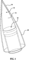
Fig. 1 is an oblique view of a hypersonic vehicle in accordance with the present invention. -
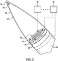
Fig. 2 is an oblique view of a radome in the hypersonic vehicle ofFig. 1 showing a sensor system in accordance with the present invention. -
Fig. 3A is an oblique view of the sensor system ofFig. 2 showing a main antenna and dual auxiliary antennas in accordance with the present invention. -
FIG. 3B is an oblique view of the dual auxiliary antennas ofFIG. 3A showing the manipulation of plasma between the auxiliary antennas. -
FIG. 3C is an oblique view of the dual auxiliary antennas ofFIG. 3A showing another manipulation of the plasma. -
FIG. 3D is an oblique view of the manipulated plasma ofFIG. 3C . -
Fig. 4 is an oblique view of the auxiliary antenna ofFig. 3 in accordance with a first exemplary embodiment of the present invention. -
Fig. 5 is an oblique view of the auxiliary antenna ofFig. 3 in accordance with a second exemplary embodiment of the present invention. - A sensor system and method for reducing plasma-induced communication inhibition for a main antenna may be used in a hypersonic vehicle. The system includes a main antenna and at least one auxiliary antenna that is used for multiple functions within the vehicle including plasma sensing around the vehicle, reducing plasma in areas that inhibit the sending and/or receipt of signals by the main antenna, and providing data link communications for the vehicle. The at least one antenna may include a plurality of antennas that are operable for switchable communication such that if plasma is detected to be inhibiting the communication of one of the antennas, another antenna may be used for communication. The use of at least one auxiliary antenna for multiple functions enables the system to accommodate for the dynamics of plasma while existing in a compact space of the vehicle. Furthermore, the sensor system may include a number of charged plates and/or electromagnets that, when combined with the auxiliary antennas, accommodate for the plasma by re-orienting the electromagnetic field or changing electric potentials in the system in response to the density of plasma.
- Referring now to
Fig. 1 , asensor system 10 may be contained in aradio frequency radome 12 located at the nose end 14 of avehicle 16. Thevehicle 16 may be a hypersonic vehicle, such as a high speed aircraft, missile, or spacecraft. A suitable missile may be a ballistic missile. Theradome 12 is configured to cover thesensor system 10 and protect thesystem 10 from environmental conditions and mechanical stresses. Theradome 12 may be conically-shaped and formed of any suitable material for withstanding aerodynamic heating and mechanical stresses. Examples of suitable materials include polymeric matrix composites, ceramic matrix composites, and monolithic ceramic materials. Theradome 12 may also be substantially transparent to allow radio frequency radiation over broadband or narrowband frequencies. - Referring in addition to
Figs. 2-3D , thesensor system 10 may include amain antenna 18 that is operable in providing various functions for thevehicle 16 during flight, such as acting as a radar or a global positioning system. Themain antenna 18 may be configured to send and/or receive signals and operable for target detection. Themain antenna 18 may be cylindrical, or disc-shaped, and positioned along a longitudinal axis of thevehicle 16. As best shown inFig. 1 , during flight of thevehicle 16, a dense plasma sheath, orplasma field 20 is formed around theradome 12 of thevehicle 16. The plasma may be hot or cold. For example, the plasma may be cold if thevehicle 16 has a portion of travel through the ionosphere, the layer of the Earth's atmosphere that is ionized by solar and cosmic radiation. Theplasma field 20 may be in a region surrounding theradome 12 of thevehicle 16 through which themain antenna 18 sends and/or receives signals. The plasma is generally dynamic and inhomogeneous such that theplasma field 20 inhibits the sending and/or receipt of signals by themain antenna 18. - The
sensor system 10 and method of reducing plasma-induced communication inhibition may be implemented in thevehicle 16. The method includes detecting a density of plasma that affects operation of themain antenna 18 and re-orienting an electromagnetic field around themain antenna 18 in response to the density detected to reduce an effect of the plasma on the operation of themain antenna 18. Thesensor system 10 and method includes at least oneauxiliary antenna 22 that may be configured to perform multiple functions, including detecting the density of the plasma in theplasma field 20, re-directing or re-orienting the electromagnetic field that is generated by theauxiliary antenna 22, and providing data link communications for thevehicle 16. - One function of the
auxiliary antenna 22 is operating as a dynamic sensor for measuring the amount or density of the plasma in theplasma field 20. As shown inFigs. 3A-3D , thesensor system 10 may include a plurality ofauxiliary antennas auxiliary antennas Figs. 4 and 5 , theauxiliary antennas auxiliary antennas Fig. 4 , and in a sideways direction, as shown inFig. 5 . The s-parameters, the combination of the S-parameters between the forward and sideways capabilities of theauxiliary antennas auxiliary antennas 22 to accommodate for plasma dynamics. The plurality ofauxiliary antennas main antenna 18 such that theauxiliary antennas auxiliary antennas plasma field 20. The plurality ofauxiliary antennas main antenna 18. - Another function of the
auxiliary antenna 22 orauxiliary antennas plasma 23 to re-orient an electromagnetic field of thesensor system 10. Theauxiliary antenna 22 is configured to radiate or receive a time-varying electromagnetic field within thesensor system 10 that may be used to control or confine theplasma 23. At least onePoynting vector plasma 23 of theplasma field 20, and in relation to the cross product of the electric and magnetic field of theauxiliary antenna 22. ThePoynting vector auxiliary antenna 22. In a configuration having dualauxiliary antennas plasma 23 may have aforward Poynting vector 23a andside Poynting vectors Poynting vectors plasma 23 in the plasma field. Theplasma 23 may not have the same orientation at the tip region of theradome 12 and the side region of theradome 12, allowing theplasma 23 to move in the direction of any of thePoynting vectors Fig. 3B , theplasma 23 may move in the direction of theside Poynting vector 23b. As shown inFigs. 3C and3D , the plasma may move in the direction of anotherside Poynting vector 23c. The dualauxiliary antennas radome 12 and the phase between theauxiliary antennas auxiliary antennas Poynting vector - As best shown in
Fig. 2 , thesensor system 10 may further include an electrical conductor extending between a metallic chargedtip 24 at the nose end 14 of thevehicle 16 and at least one chargedplate 26 positioned at themain antenna 16. Themetallic tip 24 and themetallic plate 26 may be operable to reduce the density of electrons in theplasma 23 by absorbing the electrons. Generally, the density of electrons has a directly proportional relationship to the plasma frequency, such that when the density of electrons is relatively high, the plasma frequency is also high. The density of the electrons in the plasma may also be proportional with the hypersonic speed of thevehicle 16. If the operational frequencies of thevehicle 16, such as a radio-frequency, are lower than the plasma frequency, the operational frequencies may not be able to penetrate through theplasma 23 to enable communications of thevehicle 16. Thesensor system 10 is configured to reduce the density of the electrons and in turn, reduce the plasma frequency to a frequency that is lower than the operational frequencies of thevehicle 16. When the operational frequencies are higher than the plasma frequency, the operational frequencies may penetrate through the plasma frequency and allow for functions of thevehicle 16, such as communications. - To reduce the density of the electrons, the
tip 24 andplate 26 within theradome 12 may absorb electrons and also positive ions of the plasma. Alternatively, a capacitor may be used. The electrical conductor extending between thetip 24 and theplate 26 may include any suitable conductor, such as wires. Thesensor system 10 may include a plurality of chargedplates 26 that are circumferentially spaced around themain antenna 16. The plurality ofplates 26 may be positively charged to attract electrons of the plasma while the chargedtip 24 may be negatively charged to attract positive ions of the plasma. The positive or negative potential on the plates allows thesensor system 10 to accommodate for the varying orientation of the plasma ions. - The
plasma field 20 surrounding theradome 12 may be impacted by re-orienting the electromagnetic field. Theauxiliary antenna 22 or the plurality ofauxiliary antennas controller 28 that is operatively coupled to theauxiliary antennas controller 28 may be used to adjust a phase between theauxiliary antennas Figs. 3B-D . Thecontroller 28 is configured to receive information from theauxiliary antennas plasma field 20. - Referring in addition to
Figs. 4 and 5 , theauxiliary antennas auxiliary antennas Fig. 4 , and in a sideways direction, as shown inFig. 5 . The return loss of theauxiliary antennas auxiliary antennas controller 28, the electric potential on thetip 24, which may initially be negative, and the electric potential at theplate 26, which may initially be positive, may be adjusted. Theauxiliary antenna 22 may send asignal 30 to thecontroller 28 and in response to thesignal 30, or feedback, thecontroller 28 may change the potential between the chargedtip 24 and the chargedplates 26 to re-orient the potential polarity between the chargedtip 24 andplate 26. Reducing or removing the plasma in the area allows normal operation of themain antenna 18, such as acting as a sensor for target detection. - The information regarding the plasma may further be sent to
electromagnets controller 28, to change the corresponding electromagnetic field and enabling the plasma to disperse. At least oneelectromagnet plasma field 20 surrounding the radome, with a particular focus on regions of theplasma field 20 that have a greater density of plasma. Thesensor system 10 may include a plurality ofelectromagnets main antenna 18 where signal conveyance is inhibited. - A positively charged
electromagnet 30 and a negatively chargedelectromagnet 32 may be spaced apart within theradome 12 of thevehicle 16 to re-orient the electromagnetic field. The positively charged electromagnetic 30 may include a plurality ofelectromagnets 32 located at the perimeter of themain antenna 18. The plurality ofelectromagnets 32 may be circumferentially spaced around themain antenna 18 and diametrically opposed to one another along the perimeter of themain antenna 18. The negatively chargedelectromagnet 34 may be spaced apart from the plurality of positively chargedelectromagnets 32. The negatively chargedelectromagnet 34 may be positioned at a distally opposite end of the nose end 14 of thevehicle 16 from the positively chargedelectromagnets 32 and themain antenna 18. The negatively chargedelectromagnet 34 may be coupled to themetallic tip 24 of thevehicle 16. - The electromagnets may be used to create conditions within the
sensor system 10 that are similar to the magnetic field of planet Earth. Generally, a greater amount of interference and penetration of cosmic rays and charged particles exists at the North Pole and South Pole. The magnetic field is weak along the orientation between the North Pole and the South Pole and charged particles may easily penetrate through or come into the atmosphere when aligned with the magnetic field. Charged particles have more difficulty penetrating through equator regions because the equator regions are oriented perpendicularly with respect to the orientation of the magnetic field. In the present application, the magnetic field orientation is dynamically re-oriented by changing the phase between windings of theelectromagnets auxiliary antennas - The spaced apart
electromagnets electromagnets signal 26 sent by theauxiliary antenna 22, thecontroller 24 may be configured to change the orientation, or phase of one of theelectromagnets electromagnets controller 24 and theauxiliary antennas 22 that measure the dynamics and fluctuations of plasma. The orientation of the magnetic field of theelectromagnets plasma field 20 that have denser plasma. - Referring now to
Figs. 4 and 5 , another function of the at least oneauxiliary antenna 22 includes providing data link communication, such as global positioning system communications. Theauxiliary antenna 22 may be configured to have a dual capability in that theauxiliary antenna 22 acts as an antenna structure that sends and receives signals through theplasma field 20 in a forward direction at vertical polarization, as shown inFig. 4 , and towards a side direction at vertical polarization, as shown inFig. 5 . Theauxiliary antenna 22 allows communication in different polarizations or orientations of theplasma field 20. Penetration through the plasma may occurs at a pre-determined polarization state of a radio-frequency signal and thesensor system 10 is advantageous in that it allows more degrees of freedom for penetration by the radio-frequency signal through the plasma. - The
sensor system 10 may include a plurality ofauxiliary antennas 22 that have a variable phase between one another for manipulating the plasma dynamically as previously described. The plurality ofauxiliary antennas 22 may be operable for data link communication in a switchable manner such that if the density of the plasma inhibits receipt or sending of signals by one of the plurality of auxiliary antennas, another one of the plurality ofauxiliary antennas 22 may be used for data link communication. Theauxiliary antennas 22 may be operable for detecting the density of the plasma as previously described. The radiation pattern between the auxiliary antennas may be adjusted by introducing an appropriate phase shift of the auxiliary antennas. The patterns may be adjusted to allow for the plasma to be penetrated or for the switching of theauxiliary antennas 22 to enable for communication functions of thevehicle 16. - The
auxiliary antenna 22 may have any suitable structure for a particular application. Theauxiliary antenna 22 may have an ultra-wideband antenna structure that enables the transmission of ultra-wideband signals with varying polarization subbands. As shown inFig. 4 , theauxiliary antenna 22 may be configured as a forward-radiating, or Vivaldi-type antenna. Theauxiliary antenna 22 may have a forward radiation pattern in a direction that is generally perpendicular to themain antenna 18 and parallel with theauxiliary antenna 22. As shown inFig. 5 , theauxiliary antenna 22 may have an omni-directional radiation pattern that is in a direction that is parallel with themain antenna 18 and perpendicular to theauxiliary antenna 22. The structure of theauxiliary antenna 22 is not limited to the aforementioned embodiments. - The sensor system and method as described herein has advantages over currently used systems and methods, such as providing fixed windows through plasma or providing solutions that only address the inhibition of communication without addressing the inhibition of target detection. The system and method accommodates for the inhomogeneity and dynamicity of plasma and uses a compact solution for multiple functions. The auxiliary antennas are used to clean the plasma around the radome to allow the main antenna to be operable for target detection. Additionally, the auxiliary antennas may be used for switchable data link communication and plasma sensing. Another advantage is that the
auxiliary antennas 22 may be used in a form of adaptive space or polarization diversity for their use as "data link" or other applications in relationship to the plasma dynamics. For example, if the data link signal is weak in one of the auxiliary antennas, then, another one of the data link antennas may accommodate for the weakness by taking over the function. The accommodation by the other antenna is dependent on measured feedback from the s parameter measurements. In a similar approach, theauxiliary antennas 22 may use an adaptive polarization scheme to enhance data link communications. The polarization orientation of the system and method may be used to both manipulate the plasma reduction and improve data link communications for the radome. - Still another advantage is that the configuration of the auxiliary antennas allows the auxiliary antennas to exist in the same dome area as the main antenna without interfering with the main antenna. The system also makes use of existing components from the dome region, such as the metallic tip.
- Although the invention has been shown and described with respect to a certain preferred embodiment or embodiments, it is obvious that equivalent alterations and modifications will occur to others skilled in the art upon the reading and understanding of this specification and the annexed drawings. In particular regard to the various functions performed by the above described elements (components, assemblies, devices, compositions, etc.), the terms (including a reference to a "means") used to describe such elements are intended to correspond, unless otherwise indicated, to any element which performs the specified function of the described element (i.e., that is functionally equivalent), even though not structurally equivalent to the disclosed structure which performs the function in the herein illustrated exemplary embodiment or embodiments of the invention. In addition, while a particular feature of the invention may have been described above with respect to only one or more of several illustrated embodiments, such feature may be combined with one or more other features of the other embodiments, as may be desired and advantageous for any given or particular application.
Claims (15)
- A sensor system (10) comprising:a main antenna (18) configured to send and/or receive signals;a plurality of auxiliary antennas (22a, 22b) configured to detect density of a surrounding plasma field (20) that inhibits sending and/or receipt of the signals by the main antenna, wherein the plurality of auxiliary antennas are configured to generate an electromagnetic field and are operable for data link communication; anda controller (28) operatively coupled to the plurality of auxiliary antennas;wherein the controller is configured to receive information from the plurality of auxiliary antennas regarding the density of the plasma field; andwherein the controller is further configured to adjust a phase between the auxiliary antennas in response to the detected density of the plasma field to re-orient an electromagnetic field set up by the auxiliary antennas, thereby reducing at least in part inhibition by the plasma field of the sending and/or receipt of signals of the main antenna.
- The system of claim 1, wherein the plurality of auxiliary antennas are switchable in response to density of the plasma field that inhibits the data link communication of one of the plurality of auxiliary antennas.
- The system of any of claims 1-2, further comprising at least one electromagnet (32, 34) for re-orienting the electromagnetic field.
- The system of claim 3, wherein the at least one electromagnet includes a positively charged electromagnet (32) and a negatively charged electromagnet (34) that are spaced apart, and one of the positively charged electromagnet and the negatively charged electromagnet is located distally opposite the main antenna.
- The system of claim 4, further comprising a positively or negatively charged two-phase electromagnet that is operable to change phase relative to an oppositely charged electromagnet.
- The system of any of claims 3-5, wherein the at least one electromagnet includes a plurality of electromagnets (32) that are circumferentially spaced around the main antenna.
- The system of any of claims 1-6, wherein the plurality of auxiliary antennas are circumferentially spaced around the main antenna.
- The system of claim 7, wherein the plurality of auxiliary antennas are diametrically opposed to one another.
- The system of any of claims 1-8, wherein the system is contained in a radome (12) of a hypersonic vehicle (16).
- The system of claim 9, wherein the radome includes a metallic tip (24) that is negatively or positively charged, and a plurality of charged plates (26) having an opposite charge from the metallic tip that are circumferentially spaced around the main antenna, wherein the metallic tip is located distally opposite the plurality of charged plates; and
preferably, further comprising an electromagnet (34) coupled to the metallic tip for re-orienting the electromagnetic field. - The system of any of claims 1-10, wherein the plurality of auxiliary antennas have an ultra-wideband antenna structure.
- The system of any of claims 1-11, wherein the plurality of auxiliary antennas have an omni-directional radiation pattern or a forward radiation pattern.
- A method of reducing plasma-induced communication inhibition using the sensor system according to claim 1, the method comprising:detecting a density of plasma that affects operation of the main antenna (18); andre-orienting the electromagnetic field around the main antenna in response to the density detected to reduce effect of the plasma on the main antenna.
- The method of claim 13, further comprising using the plurality of auxiliary antennas (22a, 22b) to send information regarding the density of the plasma to the controller (28) and re-orient the electromagnetic field using the controller.
- The method of claim 14, further comprising using the plurality of auxiliary antennas to generate the electromagnetic field; and
preferably , further comprising using the plurality of auxiliary antennas to detect the density of the plasma in a forward direction and a sideways direction.
Applications Claiming Priority (2)
| Application Number | Priority Date | Filing Date | Title |
|---|---|---|---|
| US15/068,026 US9972907B2 (en) | 2016-03-11 | 2016-03-11 | Method for plasma dynamic cancellation for hypersonic vehicles |
| PCT/US2016/057860 WO2017155576A1 (en) | 2016-03-11 | 2016-10-20 | Method for plasma dynamic cancellation for hypersonic vehicles |
Publications (2)
| Publication Number | Publication Date |
|---|---|
| EP3427333A1 EP3427333A1 (en) | 2019-01-16 |
| EP3427333B1 true EP3427333B1 (en) | 2019-08-14 |
Family
ID=57349111
Family Applications (1)
| Application Number | Title | Priority Date | Filing Date |
|---|---|---|---|
| EP16798303.0A Active EP3427333B1 (en) | 2016-03-11 | 2016-10-20 | Method for plasma dynamic cancellation for hypersonic vehicles |
Country Status (3)
| Country | Link |
|---|---|
| US (1) | US9972907B2 (en) |
| EP (1) | EP3427333B1 (en) |
| WO (1) | WO2017155576A1 (en) |
Families Citing this family (11)
| Publication number | Priority date | Publication date | Assignee | Title |
|---|---|---|---|---|
| US10770785B2 (en) * | 2017-04-05 | 2020-09-08 | Smartsky Networks LLC | Plasma radome with flexible density control |
| US10938430B2 (en) * | 2018-04-05 | 2021-03-02 | The Charles Stark Draper Laboratory, Inc. | Distributed antenna with closed-loop impedance matching for high speed vehicles |
| JP7446915B2 (en) * | 2020-05-25 | 2024-03-11 | 三菱重工業株式会社 | Rectification structure, flying object and spacecraft |
| US12278416B2 (en) * | 2021-07-13 | 2025-04-15 | Massachusetts Institute Of Technology | Gas injection system for plasma blackout alleviation studies |
| JP2023029154A (en) * | 2021-08-20 | 2023-03-03 | 敏之 中村 | Missile intercept device using coil gun |
| KR102635504B1 (en) * | 2021-12-06 | 2024-02-08 | 광운대학교 산학협력단 | Apparatus and method for measuring re-entry plasma characteristics |
| CN115117621B (en) * | 2022-07-12 | 2023-11-14 | 成都航空职业技术学院 | Ultra-high speed flight communication method and ultra-high speed flight antenna system |
| US12580665B2 (en) * | 2022-12-07 | 2026-03-17 | The Boeing Company | Systems and methods for communicating and sensing through plasma |
| CN116002074B (en) * | 2022-12-08 | 2026-02-27 | 哈尔滨工业大学 | A structure, method, and aircraft for overcoming the black barrier of plasma communication |
| US12573739B2 (en) * | 2023-09-11 | 2026-03-10 | Daniel Faircloth | Thermal protection system integrated antenna |
| CN117864385B (en) * | 2024-03-11 | 2024-05-14 | 中国空气动力研究与发展中心超高速空气动力研究所 | Hypersonic aircraft plasma sheath control device and flow field parameter algorithm |
Family Cites Families (7)
| Publication number | Priority date | Publication date | Assignee | Title |
|---|---|---|---|---|
| US3176227A (en) * | 1959-09-23 | 1965-03-30 | Bendix Corp | Control of ions in ionic media for communication and other purposes |
| US3317826A (en) | 1963-02-26 | 1967-05-02 | Hlf Corp | Apparatus for measuring plasma parameters about a vehicle |
| US3296531A (en) | 1964-04-29 | 1967-01-03 | Stuart L Seaton | Electrostatic plasma modulator for space vehicle re-entry communication |
| US3473116A (en) | 1967-01-30 | 1969-10-14 | Nasa | Means for measuring the electron density gradients of the plasma sheath formed around a space vehicle |
| US3758862A (en) * | 1970-08-04 | 1973-09-11 | Us Army | Rf transmission through a plasma |
| US3766562A (en) | 1972-06-21 | 1973-10-16 | Us Army | Control of electron density enveloping hypersonic vehicles |
| CN105329465B (en) | 2015-09-30 | 2017-07-28 | 哈尔滨工业大学 | A kind of method for alleviating the black barrier of spacecraft communication |
-
2016
- 2016-03-11 US US15/068,026 patent/US9972907B2/en active Active
- 2016-10-20 EP EP16798303.0A patent/EP3427333B1/en active Active
- 2016-10-20 WO PCT/US2016/057860 patent/WO2017155576A1/en not_active Ceased
Non-Patent Citations (1)
| Title |
|---|
| None * |
Also Published As
| Publication number | Publication date |
|---|---|
| US9972907B2 (en) | 2018-05-15 |
| US20170264015A1 (en) | 2017-09-14 |
| EP3427333A1 (en) | 2019-01-16 |
| WO2017155576A1 (en) | 2017-09-14 |
Similar Documents
| Publication | Publication Date | Title |
|---|---|---|
| US9972907B2 (en) | Method for plasma dynamic cancellation for hypersonic vehicles | |
| US4989006A (en) | Microwave absorption system | |
| US9979088B2 (en) | Mechanical antenna | |
| US7212147B2 (en) | Method of agile reduction of radar cross section using electromagnetic channelization | |
| CN101256235A (en) | Subsurface imaging radar | |
| CN108736174B (en) | Plasma switch array antenna | |
| Kamboj et al. | Development of reconfigurable plasma column antenna | |
| EP2312339B1 (en) | Multiple beam directed energy system and operating method thereof | |
| US7193556B1 (en) | System and method for the measurement of full relative position and orientation of objects | |
| CN103531897A (en) | Magnetic window antenna for avoiding communication blackout of near space plasma shell jacket | |
| Razooqi et al. | Drones neutralized by utilize electromagnetic pulse (EMP) system | |
| ES2895123T3 (en) | Method for dynamic heat detection in hypersonic applications | |
| EP4428044A1 (en) | Outer-space-based debris detection system and associated methods | |
| Sripho et al. | Comparison of antenna for DTI rocket telemetry system | |
| Rudyk et al. | Using stealth technologies in mobile robotic complexes and methods of detection of low-sighted objects | |
| Tariq et al. | Characterization of a 60 GHz scattered wireless channel with different antenna polarizations for underground multimedia applications | |
| Davis et al. | Hypersonic or re-entry plasma communication | |
| Bai et al. | Effect of plasma sheath covering spacecraft-borne array antenna on direction-of-arrival estimation | |
| RU2226278C2 (en) | Method of counteraction to air defense aids and device for its realization | |
| CA2632220C (en) | Method of agile reduction of radar cross section using electromagnetic channelization | |
| Kishore | Antenna and wave propagation | |
| Poirier | Effects of the Reentry Plasma Sheath on Microwave Antenna Performance: Trailblazer II Rocket Results of 18 Jun 1967 | |
| Tsai et al. | Design and implement of transceiver system for hybrid rocket with coplanar wraparound antenna at 433 MHz | |
| Davis et al. | Communication through hypersonic or re-entry plasmas | |
| Pu et al. | Design and Antenna Performance Calculation Method for Integrating Distance Sensors with Seekers |
Legal Events
| Date | Code | Title | Description |
|---|---|---|---|
| STAA | Information on the status of an ep patent application or granted ep patent |
Free format text: STATUS: UNKNOWN |
|
| STAA | Information on the status of an ep patent application or granted ep patent |
Free format text: STATUS: THE INTERNATIONAL PUBLICATION HAS BEEN MADE |
|
| PUAI | Public reference made under article 153(3) epc to a published international application that has entered the european phase |
Free format text: ORIGINAL CODE: 0009012 |
|
| STAA | Information on the status of an ep patent application or granted ep patent |
Free format text: STATUS: REQUEST FOR EXAMINATION WAS MADE |
|
| 17P | Request for examination filed |
Effective date: 20181005 |
|
| AK | Designated contracting states |
Kind code of ref document: A1 Designated state(s): AL AT BE BG CH CY CZ DE DK EE ES FI FR GB GR HR HU IE IS IT LI LT LU LV MC MK MT NL NO PL PT RO RS SE SI SK SM TR |
|
| AX | Request for extension of the european patent |
Extension state: BA ME |
|
| GRAP | Despatch of communication of intention to grant a patent |
Free format text: ORIGINAL CODE: EPIDOSNIGR1 |
|
| STAA | Information on the status of an ep patent application or granted ep patent |
Free format text: STATUS: GRANT OF PATENT IS INTENDED |
|
| DAV | Request for validation of the european patent (deleted) | ||
| DAX | Request for extension of the european patent (deleted) | ||
| INTG | Intention to grant announced |
Effective date: 20190418 |
|
| GRAS | Grant fee paid |
Free format text: ORIGINAL CODE: EPIDOSNIGR3 |
|
| GRAA | (expected) grant |
Free format text: ORIGINAL CODE: 0009210 |
|
| STAA | Information on the status of an ep patent application or granted ep patent |
Free format text: STATUS: THE PATENT HAS BEEN GRANTED |
|
| AK | Designated contracting states |
Kind code of ref document: B1 Designated state(s): AL AT BE BG CH CY CZ DE DK EE ES FI FR GB GR HR HU IE IS IT LI LT LU LV MC MK MT NL NO PL PT RO RS SE SI SK SM TR |
|
| REG | Reference to a national code |
Ref country code: GB Ref legal event code: FG4D |
|
| REG | Reference to a national code |
Ref country code: CH Ref legal event code: EP Ref country code: AT Ref legal event code: REF Ref document number: 1168110 Country of ref document: AT Kind code of ref document: T Effective date: 20190815 |
|
| REG | Reference to a national code |
Ref country code: IE Ref legal event code: FG4D |
|
| REG | Reference to a national code |
Ref country code: DE Ref legal event code: R096 Ref document number: 602016018756 Country of ref document: DE |
|
| REG | Reference to a national code |
Ref country code: NL Ref legal event code: MP Effective date: 20190814 |
|
| REG | Reference to a national code |
Ref country code: LT Ref legal event code: MG4D |
|
| PG25 | Lapsed in a contracting state [announced via postgrant information from national office to epo] |
Ref country code: HR Free format text: LAPSE BECAUSE OF FAILURE TO SUBMIT A TRANSLATION OF THE DESCRIPTION OR TO PAY THE FEE WITHIN THE PRESCRIBED TIME-LIMIT Effective date: 20190814 Ref country code: SE Free format text: LAPSE BECAUSE OF FAILURE TO SUBMIT A TRANSLATION OF THE DESCRIPTION OR TO PAY THE FEE WITHIN THE PRESCRIBED TIME-LIMIT Effective date: 20190814 Ref country code: NO Free format text: LAPSE BECAUSE OF FAILURE TO SUBMIT A TRANSLATION OF THE DESCRIPTION OR TO PAY THE FEE WITHIN THE PRESCRIBED TIME-LIMIT Effective date: 20191114 Ref country code: FI Free format text: LAPSE BECAUSE OF FAILURE TO SUBMIT A TRANSLATION OF THE DESCRIPTION OR TO PAY THE FEE WITHIN THE PRESCRIBED TIME-LIMIT Effective date: 20190814 Ref country code: PT Free format text: LAPSE BECAUSE OF FAILURE TO SUBMIT A TRANSLATION OF THE DESCRIPTION OR TO PAY THE FEE WITHIN THE PRESCRIBED TIME-LIMIT Effective date: 20191216 Ref country code: NL Free format text: LAPSE BECAUSE OF FAILURE TO SUBMIT A TRANSLATION OF THE DESCRIPTION OR TO PAY THE FEE WITHIN THE PRESCRIBED TIME-LIMIT Effective date: 20190814 Ref country code: BG Free format text: LAPSE BECAUSE OF FAILURE TO SUBMIT A TRANSLATION OF THE DESCRIPTION OR TO PAY THE FEE WITHIN THE PRESCRIBED TIME-LIMIT Effective date: 20191114 Ref country code: LT Free format text: LAPSE BECAUSE OF FAILURE TO SUBMIT A TRANSLATION OF THE DESCRIPTION OR TO PAY THE FEE WITHIN THE PRESCRIBED TIME-LIMIT Effective date: 20190814 |
|
| REG | Reference to a national code |
Ref country code: AT Ref legal event code: MK05 Ref document number: 1168110 Country of ref document: AT Kind code of ref document: T Effective date: 20190814 |
|
| PG25 | Lapsed in a contracting state [announced via postgrant information from national office to epo] |
Ref country code: RS Free format text: LAPSE BECAUSE OF FAILURE TO SUBMIT A TRANSLATION OF THE DESCRIPTION OR TO PAY THE FEE WITHIN THE PRESCRIBED TIME-LIMIT Effective date: 20190814 Ref country code: IS Free format text: LAPSE BECAUSE OF FAILURE TO SUBMIT A TRANSLATION OF THE DESCRIPTION OR TO PAY THE FEE WITHIN THE PRESCRIBED TIME-LIMIT Effective date: 20191214 Ref country code: LV Free format text: LAPSE BECAUSE OF FAILURE TO SUBMIT A TRANSLATION OF THE DESCRIPTION OR TO PAY THE FEE WITHIN THE PRESCRIBED TIME-LIMIT Effective date: 20190814 Ref country code: AL Free format text: LAPSE BECAUSE OF FAILURE TO SUBMIT A TRANSLATION OF THE DESCRIPTION OR TO PAY THE FEE WITHIN THE PRESCRIBED TIME-LIMIT Effective date: 20190814 Ref country code: ES Free format text: LAPSE BECAUSE OF FAILURE TO SUBMIT A TRANSLATION OF THE DESCRIPTION OR TO PAY THE FEE WITHIN THE PRESCRIBED TIME-LIMIT Effective date: 20190814 Ref country code: GR Free format text: LAPSE BECAUSE OF FAILURE TO SUBMIT A TRANSLATION OF THE DESCRIPTION OR TO PAY THE FEE WITHIN THE PRESCRIBED TIME-LIMIT Effective date: 20191115 |
|
| PG25 | Lapsed in a contracting state [announced via postgrant information from national office to epo] |
Ref country code: TR Free format text: LAPSE BECAUSE OF FAILURE TO SUBMIT A TRANSLATION OF THE DESCRIPTION OR TO PAY THE FEE WITHIN THE PRESCRIBED TIME-LIMIT Effective date: 20190814 |
|
| PG25 | Lapsed in a contracting state [announced via postgrant information from national office to epo] |
Ref country code: PL Free format text: LAPSE BECAUSE OF FAILURE TO SUBMIT A TRANSLATION OF THE DESCRIPTION OR TO PAY THE FEE WITHIN THE PRESCRIBED TIME-LIMIT Effective date: 20190814 Ref country code: DK Free format text: LAPSE BECAUSE OF FAILURE TO SUBMIT A TRANSLATION OF THE DESCRIPTION OR TO PAY THE FEE WITHIN THE PRESCRIBED TIME-LIMIT Effective date: 20190814 Ref country code: RO Free format text: LAPSE BECAUSE OF FAILURE TO SUBMIT A TRANSLATION OF THE DESCRIPTION OR TO PAY THE FEE WITHIN THE PRESCRIBED TIME-LIMIT Effective date: 20190814 Ref country code: IT Free format text: LAPSE BECAUSE OF FAILURE TO SUBMIT A TRANSLATION OF THE DESCRIPTION OR TO PAY THE FEE WITHIN THE PRESCRIBED TIME-LIMIT Effective date: 20190814 Ref country code: EE Free format text: LAPSE BECAUSE OF FAILURE TO SUBMIT A TRANSLATION OF THE DESCRIPTION OR TO PAY THE FEE WITHIN THE PRESCRIBED TIME-LIMIT Effective date: 20190814 Ref country code: AT Free format text: LAPSE BECAUSE OF FAILURE TO SUBMIT A TRANSLATION OF THE DESCRIPTION OR TO PAY THE FEE WITHIN THE PRESCRIBED TIME-LIMIT Effective date: 20190814 |
|
| PG25 | Lapsed in a contracting state [announced via postgrant information from national office to epo] |
Ref country code: SM Free format text: LAPSE BECAUSE OF FAILURE TO SUBMIT A TRANSLATION OF THE DESCRIPTION OR TO PAY THE FEE WITHIN THE PRESCRIBED TIME-LIMIT Effective date: 20190814 Ref country code: CZ Free format text: LAPSE BECAUSE OF FAILURE TO SUBMIT A TRANSLATION OF THE DESCRIPTION OR TO PAY THE FEE WITHIN THE PRESCRIBED TIME-LIMIT Effective date: 20190814 Ref country code: IS Free format text: LAPSE BECAUSE OF FAILURE TO SUBMIT A TRANSLATION OF THE DESCRIPTION OR TO PAY THE FEE WITHIN THE PRESCRIBED TIME-LIMIT Effective date: 20200224 Ref country code: MC Free format text: LAPSE BECAUSE OF FAILURE TO SUBMIT A TRANSLATION OF THE DESCRIPTION OR TO PAY THE FEE WITHIN THE PRESCRIBED TIME-LIMIT Effective date: 20190814 Ref country code: SK Free format text: LAPSE BECAUSE OF FAILURE TO SUBMIT A TRANSLATION OF THE DESCRIPTION OR TO PAY THE FEE WITHIN THE PRESCRIBED TIME-LIMIT Effective date: 20190814 |
|
| REG | Reference to a national code |
Ref country code: CH Ref legal event code: PL |
|
| REG | Reference to a national code |
Ref country code: DE Ref legal event code: R097 Ref document number: 602016018756 Country of ref document: DE |
|
| PLBE | No opposition filed within time limit |
Free format text: ORIGINAL CODE: 0009261 |
|
| STAA | Information on the status of an ep patent application or granted ep patent |
Free format text: STATUS: NO OPPOSITION FILED WITHIN TIME LIMIT |
|
| PG2D | Information on lapse in contracting state deleted |
Ref country code: IS |
|
| PG25 | Lapsed in a contracting state [announced via postgrant information from national office to epo] |
Ref country code: CH Free format text: LAPSE BECAUSE OF NON-PAYMENT OF DUE FEES Effective date: 20191031 Ref country code: LU Free format text: LAPSE BECAUSE OF NON-PAYMENT OF DUE FEES Effective date: 20191020 Ref country code: LI Free format text: LAPSE BECAUSE OF NON-PAYMENT OF DUE FEES Effective date: 20191031 |
|
| 26N | No opposition filed |
Effective date: 20200603 |
|
| REG | Reference to a national code |
Ref country code: BE Ref legal event code: MM Effective date: 20191031 |
|
| PG25 | Lapsed in a contracting state [announced via postgrant information from national office to epo] |
Ref country code: BE Free format text: LAPSE BECAUSE OF NON-PAYMENT OF DUE FEES Effective date: 20191031 |
|
| PG25 | Lapsed in a contracting state [announced via postgrant information from national office to epo] |
Ref country code: IE Free format text: LAPSE BECAUSE OF NON-PAYMENT OF DUE FEES Effective date: 20191020 |
|
| PG25 | Lapsed in a contracting state [announced via postgrant information from national office to epo] |
Ref country code: CY Free format text: LAPSE BECAUSE OF FAILURE TO SUBMIT A TRANSLATION OF THE DESCRIPTION OR TO PAY THE FEE WITHIN THE PRESCRIBED TIME-LIMIT Effective date: 20190814 |
|
| PG25 | Lapsed in a contracting state [announced via postgrant information from national office to epo] |
Ref country code: HU Free format text: LAPSE BECAUSE OF FAILURE TO SUBMIT A TRANSLATION OF THE DESCRIPTION OR TO PAY THE FEE WITHIN THE PRESCRIBED TIME-LIMIT; INVALID AB INITIO Effective date: 20161020 Ref country code: MT Free format text: LAPSE BECAUSE OF FAILURE TO SUBMIT A TRANSLATION OF THE DESCRIPTION OR TO PAY THE FEE WITHIN THE PRESCRIBED TIME-LIMIT Effective date: 20190814 |
|
| PG25 | Lapsed in a contracting state [announced via postgrant information from national office to epo] |
Ref country code: SI Free format text: LAPSE BECAUSE OF FAILURE TO SUBMIT A TRANSLATION OF THE DESCRIPTION OR TO PAY THE FEE WITHIN THE PRESCRIBED TIME-LIMIT Effective date: 20190814 |
|
| PG25 | Lapsed in a contracting state [announced via postgrant information from national office to epo] |
Ref country code: MK Free format text: LAPSE BECAUSE OF FAILURE TO SUBMIT A TRANSLATION OF THE DESCRIPTION OR TO PAY THE FEE WITHIN THE PRESCRIBED TIME-LIMIT Effective date: 20190814 |
|
| P01 | Opt-out of the competence of the unified patent court (upc) registered |
Effective date: 20230530 |
|
| PGFP | Annual fee paid to national office [announced via postgrant information from national office to epo] |
Ref country code: GB Payment date: 20250923 Year of fee payment: 10 |
|
| PGFP | Annual fee paid to national office [announced via postgrant information from national office to epo] |
Ref country code: FR Payment date: 20250923 Year of fee payment: 10 |
|
| PGFP | Annual fee paid to national office [announced via postgrant information from national office to epo] |
Ref country code: DE Payment date: 20250923 Year of fee payment: 10 |