EP3426422B1 - Method for automated robotic manufacture of variable-density and arbitrary shaped metallic meshes - Google Patents
Method for automated robotic manufacture of variable-density and arbitrary shaped metallic meshes Download PDFInfo
- Publication number
- EP3426422B1 EP3426422B1 EP17715403.6A EP17715403A EP3426422B1 EP 3426422 B1 EP3426422 B1 EP 3426422B1 EP 17715403 A EP17715403 A EP 17715403A EP 3426422 B1 EP3426422 B1 EP 3426422B1
- Authority
- EP
- European Patent Office
- Prior art keywords
- dimensional
- wires
- effector
- autonomous mobile
- self
- Prior art date
- Legal status (The legal status is an assumption and is not a legal conclusion. Google has not performed a legal analysis and makes no representation as to the accuracy of the status listed.)
- Active
Links
Images





Classifications
-
- B—PERFORMING OPERATIONS; TRANSPORTING
- B25—HAND TOOLS; PORTABLE POWER-DRIVEN TOOLS; MANIPULATORS
- B25J—MANIPULATORS; CHAMBERS PROVIDED WITH MANIPULATION DEVICES
- B25J9/00—Program-controlled manipulators
- B25J9/16—Program controls
- B25J9/1656—Program controls characterised by programming, planning systems for manipulators
- B25J9/1669—Program controls characterised by programming, planning systems for manipulators characterised by special application, e.g. multi-arm co-operation, assembly, grasping
-
- B—PERFORMING OPERATIONS; TRANSPORTING
- B21—MECHANICAL METAL-WORKING WITHOUT ESSENTIALLY REMOVING MATERIAL; PUNCHING METAL
- B21F—WORKING OR PROCESSING OF METAL WIRE
- B21F27/00—Making wire network, i.e. wire nets
- B21F27/08—Making wire network, i.e. wire nets with additional connecting elements or material at crossings
- B21F27/10—Making wire network, i.e. wire nets with additional connecting elements or material at crossings with soldered or welded crossings
-
- B—PERFORMING OPERATIONS; TRANSPORTING
- B21—MECHANICAL METAL-WORKING WITHOUT ESSENTIALLY REMOVING MATERIAL; PUNCHING METAL
- B21F—WORKING OR PROCESSING OF METAL WIRE
- B21F27/00—Making wire network, i.e. wire nets
- B21F27/12—Making special types or portions of network by methods or means specially adapted therefor
-
- B—PERFORMING OPERATIONS; TRANSPORTING
- B25—HAND TOOLS; PORTABLE POWER-DRIVEN TOOLS; MANIPULATORS
- B25J—MANIPULATORS; CHAMBERS PROVIDED WITH MANIPULATION DEVICES
- B25J11/00—Manipulators not otherwise provided for
- B25J11/005—Manipulators for mechanical processing tasks
-
- B—PERFORMING OPERATIONS; TRANSPORTING
- B25—HAND TOOLS; PORTABLE POWER-DRIVEN TOOLS; MANIPULATORS
- B25J—MANIPULATORS; CHAMBERS PROVIDED WITH MANIPULATION DEVICES
- B25J9/00—Program-controlled manipulators
- B25J9/16—Program controls
- B25J9/1615—Program controls characterised by special kind of manipulator, e.g. planar, scara, gantry, cantilever, space, closed chain, passive/active joints and tendon driven manipulators
- B25J9/162—Mobile manipulator, movable base with manipulator arm mounted on it
-
- B—PERFORMING OPERATIONS; TRANSPORTING
- B25—HAND TOOLS; PORTABLE POWER-DRIVEN TOOLS; MANIPULATORS
- B25J—MANIPULATORS; CHAMBERS PROVIDED WITH MANIPULATION DEVICES
- B25J9/00—Program-controlled manipulators
- B25J9/16—Program controls
- B25J9/1656—Program controls characterised by programming, planning systems for manipulators
- B25J9/1671—Program controls characterised by programming, planning systems for manipulators characterised by simulation, either to verify existing program or to create and verify new program, CAD/CAM oriented, graphic oriented programming systems
-
- B—PERFORMING OPERATIONS; TRANSPORTING
- B25—HAND TOOLS; PORTABLE POWER-DRIVEN TOOLS; MANIPULATORS
- B25J—MANIPULATORS; CHAMBERS PROVIDED WITH MANIPULATION DEVICES
- B25J9/00—Program-controlled manipulators
- B25J9/16—Program controls
- B25J9/1679—Program controls characterised by the tasks executed
- B25J9/1687—Assembly, peg and hole, palletising, straight line, weaving pattern movement
Definitions
- This invention describes a method for the fabrication of threedimensional meshes, in particular freeform, volumetric metallic meshes with variable density. Specific applications include concrete formwork and reinforcement but can find use in other construction purposes as well.
- Metal meshes are used for a wide variety of applications, ranging from lightweight structural components to reinforcements of composite building structures or scaffolding and substructures. These meshes mainly follow simple rectangular or single curved geometries as currently metal meshes can only be produced economically as planar two-dimensional mats with equally spaced cell sizes. In order to meet the demand for complex construction geometries and to therefore enable the fabrication of non-standard, structurally optimized steel reinforced concrete structures, three-dimensionally shaped metal meshes are required. To create three-dimensional metal meshes out of a continuous metal wire in an automated manner, it is required to integrate metal wire straightening, bending, feeding, cutting and welding within a digitally-controlled process that allows for a) variable mesh geometries and b) automated manufacturing.
- the second strategy to manufacture three-dimensional mesh structures starts exactly at this point.
- Two flat steel mats or steel meshes are connected by spacers at a certain distance in order to obtain a three-dimensional mesh. Since the automatic production of the initial mesh faces is usually limited to planar surfaces, also the resulting meshes are constrained to planar geometries, such as, for example, volumetric sandwich meshes (see for example CN 1171709 C , "Productive method and apparatus for 3D cross-linked sandwich screen plate").
- WO 2015/034438 A1 forms the basis for the preamble of claim 1.
- An aspect of the present disclosure is a robotic setup including a custom multifunctional robotic end-effector that facilitates the digitally controlled fabrication of threedimensional metal meshes with locally and globally varying volume, curvature and cell size.
- a further aspect of the present disclosure is a digital process to produce three dimensional metallic meshes, of varying shapes and density, and the robotic setup which automates this digital process.
- the novelty of the invention not only lies in the robust integration of key subfunctionalities like wire straightening, feeding, bending, cutting and cross wire welding of the proposed method and setup into a single, robotically guided and digitally controlled endeffector mounted on a mobile robotic manipulator but also in the sequence in which they are executed.
- the machine is static and the building element moves through the machine, here preferably the building element remains static and the machine (robotic setup) moves in order to fabricate the structure.
- a further aspect of the present disclosure is a digital design and control process to robotically produce three-dimensional metallic meshes, of varying volume, shape and density, which allows a complete digital parameterization of a mesh geometry - including overall dimension, shape and global/local geometric manipulation - and to export specific design data sets and to directly transfer it to a robotic control system.
- this allows to automatically (design and) fabrication variable, non-standard three-dimensional meshes, which can be used in particular as concrete reinforcements or lost formwork (or as a combination of these two).
- the mobile manufacturing device comprises a specialised end-effector which is adapted to move along a three-dimensional structure to be produced and is adapted to carry out at least some of the steps of the method for producing three-dimensional, highly variable lattice or mesh structures according to the invention.
- the present invention relates to a method of producing three-dimensional, highly variable lattice or mesh structures as defined in appended claim 1.
- a custom control software Based on a parametric three-dimensional model of the mesh, for which its local and global curvature, its height and length can be varied, a custom control software generates motion commands for the robotic setup which comprises of a mobile manipulator and a specialized end-effector.
- the mobile manipulator includes an autonomous mobile base, which can selflocalize in its environment with the help of on-board sensors. Further, the mobile manipulator includes an robotic arm together with a specialized self-contained end-effector, which is mounted to the robotic arm.
- the self-contained end-effector can include additional sensing, both for feedback from cutting and welding as well as to provide additional localization through for example, but not limited to cameras and lasers and inertial measurement units.
- the building element remains static and the machine (robotic setup) moves in order to fabricate the structure.
- This inversion achieved through the use of an autonomous mobile manipulator significantly increases the dimensions and articulation of geometries that can be fabricated and imposes fewer restrictions on the achievable size of the structure being built. Especially it allows for an in situ production and specialised geometric and structural adaptation of the meshes, even within constraints of a building shell.
- This digitally-controlled manufacturing of three-dimensional metal meshes comprises features which can be totally automated not only separately but also as a programmable sequence of operations.
- the present invention therefore describes a unique construction method and robotic setup (including the robotic end-effector), which provides a robust integration of all these features and which is totally automated.
- This advantage of total digitally-controlled automation not present in the state of art, enables significantly enhanced geometric freedom in determining, for example, overall dimension and volume as well as formal articulation and density of metal wire meshes. This also enables to achieve differentiation of a mesh geometry locally in order to adapt the structure's geometry locally in areas where stress concentration is higher due to external loads.
- the key advantage is the full automation of the process and the high flexibility with regards to non-standard geometries that can be produced without having to change the machine setup and or the overall design approach.
- This is possible through the aforementioned inversion of static machine and mobile building element.
- the machine setup had to change in order to accommodate varying building element geometries
- the mobile manipulator remains unaffected by the geometry of the building element due to the inherent high flexibility of the applied method and setup.
- this ability to mass customize building elements allows fabricating geometries which are tailored exactly towards their specific load case or purpose, which in turn allows for significant savings in material (such as for formwork, reinforcement or concrete filling).
- the invention can be used for other concrete construction systems. Additionally the method could be used for other structural applications that depend on geometric flexibility (for example volume and shape) without having to fill the mesh with concrete or other materials. Here the focus could potentially be on fences, cages, lightweight structures or other load-bearing structures and scaffoldings.
Landscapes
- Engineering & Computer Science (AREA)
- Mechanical Engineering (AREA)
- Robotics (AREA)
- Health & Medical Sciences (AREA)
- General Health & Medical Sciences (AREA)
- Orthopedic Medicine & Surgery (AREA)
- Manipulator (AREA)
- Numerical Control (AREA)
- Wire Processing (AREA)
Description
- This invention describes a method for the fabrication of threedimensional meshes, in particular freeform, volumetric metallic meshes with variable density. Specific applications include concrete formwork and reinforcement but can find use in other construction purposes as well.
- Metal meshes are used for a wide variety of applications, ranging from lightweight structural components to reinforcements of composite building structures or scaffolding and substructures. These meshes mainly follow simple rectangular or single curved geometries as currently metal meshes can only be produced economically as planar two-dimensional mats with equally spaced cell sizes. In order to meet the demand for complex construction geometries and to therefore enable the fabrication of non-standard, structurally optimized steel reinforced concrete structures, three-dimensionally shaped metal meshes are required. To create three-dimensional metal meshes out of a continuous metal wire in an automated manner, it is required to integrate metal wire straightening, bending, feeding, cutting and welding within a digitally-controlled process that allows for a) variable mesh geometries and b) automated manufacturing.
- Previously, geometrically complex, three-dimensional metal meshes were difficult to produce. Mainly two approaches were applied:
In the first approach, the single wires are bent, assembled and subsequently welded together. Only one surface is fabricated at a time. Successive steps are needed in order to create such three-dimensional mesh structures. - The second strategy to manufacture three-dimensional mesh structures starts exactly at this point. Two flat steel mats or steel meshes are connected by spacers at a certain distance in order to obtain a three-dimensional mesh. Since the automatic production of the initial mesh faces is usually limited to planar surfaces, also the resulting meshes are constrained to planar geometries, such as, for example, volumetric sandwich meshes (see for example
CN 1171709 C , "Productive method and apparatus for 3D cross-linked sandwich screen plate"). -
WO 2015/034438 A1 , from the present applicant, forms the basis for the preamble of claim 1. - An aspect of the present disclosure is a robotic setup including a custom multifunctional robotic end-effector that facilitates the digitally controlled fabrication of threedimensional metal meshes with locally and globally varying volume, curvature and cell size.
- A further aspect of the present disclosure is a digital process to produce three dimensional metallic meshes, of varying shapes and density, and the robotic setup which automates this digital process. Overall, the novelty of the invention not only lies in the robust integration of key subfunctionalities like wire straightening, feeding, bending, cutting and cross wire welding of the proposed method and setup into a single, robotically guided and digitally controlled endeffector mounted on a mobile robotic manipulator but also in the sequence in which they are executed. Whereas in current applications the machine is static and the building element moves through the machine, here preferably the building element remains static and the machine (robotic setup) moves in order to fabricate the structure. This inversion significantly increases the range of geometries that can be fabricated and imposes fewer restrictions on the achievable size of the structure being built. In turn, the proposed method and endeffector setup is also transferable to stationary robotic machinery (e.g. automated prefabrication).
- A further aspect of the present disclosure is a digital design and control process to robotically produce three-dimensional metallic meshes, of varying volume, shape and density, which allows a complete digital parameterization of a mesh geometry - including overall dimension, shape and global/local geometric manipulation - and to export specific design data sets and to directly transfer it to a robotic control system. As a consequence, this allows to automatically (design and) fabrication variable, non-standard three-dimensional meshes, which can be used in particular as concrete reinforcements or lost formwork (or as a combination of these two).
- The present disclosure comprises the following possible characteristics of the autonomous mobile manipulator and the autonomous mesh building method:
- 1. The autonomous mobile manipulator, as a first step, lays down the metal wires horizontally at defined vertical distances and in prescribed lengths in three-dimensional space. This can be achieved through the use of a mobile manipulator (e.g. a robotic arm), which can guide and lay the horizontal wires at prescribed vertical distance to a prescribed length.
- 2. The self-contained end-effector of the autonomous mobile manipulator provides for an actuated axis of rotation, which can bend these laid horizontal wires, from step 1, at prescribed points by prescribed angles. This can be achieved by a user-defined end-effector attached to the above mobile manipulator, which provides for an actuated axis of rotation and controls the magnitude of wire bending.
- 3. The self-contained end-effector of the autonomous mobile manipulator includes a mechanism to grasp and feed wires vertically in discrete steps of varying lengths.
- 4. The spatial arrangement of the horizontal wires from step 1 and vertical wires from step 3, dictated by the 3-dimensional parametric model, is controlled and manufactured by the mobile manipulator.
- 5. The self-contained end-effector of the autonomous mobile manipulator provides for an mechanism to bring the horizontal wires, from step 1, and vertical wires, from step 3, together to form cross-wire connections.
- 6. The self-contained end-effector of the autonomous mobile manipulator includes a mechanism to automatically weld the cross-wire connections together to form cross-wire joints.
- 7. The self-contained end-effector of the autonomous mobile manipulator includes an wire cutting mechanism, which can cut the vertical wires, from step 3, at varying lengths.
- 8. By repeating steps from 1-7, mesh with varying length, height and varying local, global curvature can be fabricated in an automated manner. This is made possible by selflocalization of the mobile manipulator as it changes its position and orientation while building the mesh.
- 9. The mobile manipulator may comprise on-board sensing, for example cameras, which can detect the curvature of the actually built mesh locally and/or globally and autonomously realign the mesh geometry and correct for any deviations from the given parametric model of the mesh and/or occurring unmodeled material effects.
- 10. Arbitrary length of the mesh can be fabricated in an automated manner. This is made possible by self-localization of the mobile manipulator as it changes its position and orientation while building the mesh.
- Preferably, the mobile manufacturing device comprises a specialised end-effector which is adapted to move along a three-dimensional structure to be produced and is adapted to carry out at least some of the steps of the method for producing three-dimensional, highly variable lattice or mesh structures according to the invention.
- The present invention relates to a method of producing three-dimensional, highly variable lattice or mesh structures as defined in appended claim 1.
- Based on a parametric three-dimensional model of the mesh, for which its local and global curvature, its height and length can be varied, a custom control software generates motion commands for the robotic setup which comprises of a mobile manipulator and a specialized end-effector. The mobile manipulator includes an autonomous mobile base, which can selflocalize in its environment with the help of on-board sensors. Further, the mobile manipulator includes an robotic arm together with a specialized self-contained end-effector, which is mounted to the robotic arm. The self-contained end-effector can include additional sensing, both for feedback from cutting and welding as well as to provide additional localization through for example, but not limited to cameras and lasers and inertial measurement units.
- Contrary to the known machines and methods in the area of the invention, preferably the building element (mesh) remains static and the machine (robotic setup) moves in order to fabricate the structure. This inversion achieved through the use of an autonomous mobile manipulator significantly increases the dimensions and articulation of geometries that can be fabricated and imposes fewer restrictions on the achievable size of the structure being built. Especially it allows for an in situ production and specialised geometric and structural adaptation of the meshes, even within constraints of a building shell.
- This digitally-controlled manufacturing of three-dimensional metal meshes comprises features which can be totally automated not only separately but also as a programmable sequence of operations. The present invention therefore describes a unique construction method and robotic setup (including the robotic end-effector), which provides a robust integration of all these features and which is totally automated. This advantage of total digitally-controlled automation, not present in the state of art, enables significantly enhanced geometric freedom in determining, for example, overall dimension and volume as well as formal articulation and density of metal wire meshes. This also enables to achieve differentiation of a mesh geometry locally in order to adapt the structure's geometry locally in areas where stress concentration is higher due to external loads. Currently, this combination of digitally-controlled automation and high geometric variability is especially lacking for the production of three-dimensional metal meshes, which is the subject of this invention. Using a mobile robotic platform for guiding the mentioned custom end-effector also allows to apply the method directly on the construction site and to robotically manufacture meshes with no a priori size limits.
- On the most general level, the key advantage is the full automation of the process and the high flexibility with regards to non-standard geometries that can be produced without having to change the machine setup and or the overall design approach. This is possible through the aforementioned inversion of static machine and mobile building element. Whereas previously the machine setup had to change in order to accommodate varying building element geometries, now the mobile manipulator remains unaffected by the geometry of the building element due to the inherent high flexibility of the applied method and setup. Moreover, this ability to mass customize building elements allows fabricating geometries which are tailored exactly towards their specific load case or purpose, which in turn allows for significant savings in material (such as for formwork, reinforcement or concrete filling).
- In its original purpose as combined concrete formwork and reinforcement the invention can be used for other concrete construction systems. Additionally the method could be used for other structural applications that depend on geometric flexibility (for example volume and shape) without having to fill the mesh with concrete or other materials. Here the focus could potentially be on fences, cages, lightweight structures or other load-bearing structures and scaffoldings.
- The invention is described by means of the enclosed figures showing preferred embodiments of the invention.
-
Figures 1 and2 show photographs of the mobile manufacturing device according to the invention as well as of its specialised end-effector. -
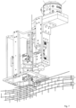
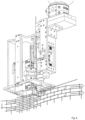
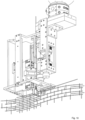
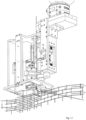
Figures 3 and4 show the end-effector producing a three-dimensional mesh. - In
figures 5 to 15 the end-effector producing three-dimensional mesh is shown, wherein the single figures show details of the respective steps of the method for producing threedimensional, highly variable lattice or mesh structures, as grasping and feeding wires, positioning wires, cutting wires, bending wires, welding wires, straightening of wires.
Claims (2)
- Method for producing three-dimensional, highly variable lattice or mesh structures by means of a mobile manufacturing device, the mobile manufacturing device being adapted to move along a three-dimensional structure to be produced, and wherein the mobile manufacturing device comprises a means for detection of its position relative to the dimensional structure to be produced, so that the mobile manufacturing device is able to produce the three-dimensional structure as an autonomous robot, wherein the mobile manufacturing device is moved on a two-dimensional plane, characterized in that it manufactures, by means of its end-effector, a three-dimensional lattice or mesh structure by providing wires in horizontal as well as in non-horizontal orientation and by bending and/or connecting a plurality of these wires, the method comprising the steps of:Step 1: an autonomous mobile manipulator lays down a metal wire horizontally at a defined vertical distance from a previously laid horizontal wire, in a prescribed length in three-dimensional space;Step 2: a self-contained end-effector of the autonomous mobile manipulator bends said laid horizontal wire from step 1 at prescribed points by prescribed angles;Step 3: the self-contained end-effector of the autonomous mobile manipulator grasps and feeds wires vertically in discrete steps of varying lengths;Step 4: the autonomous mobile manipulator controls a spatial arrangement of the horizontal wires from step 1 and vertical wires from step 3 dictated by a 3-dimensional parametric model;Step 5: the self-contained end-effector of the autonomous mobile manipulator forms crosswire connections by bringing the horizontal wires from step 1 and vertical wires from step 3 together;Step 6: the self-contained end-effector of the autonomous mobile manipulator welds the cross-wire connections from step 5 together to form cross-wire joints; andStep 7: the self-contained end-effector of the autonomous mobile manipulator cuts the vertical wires from step 3 at varying lengths;Step 8: repeating steps 1-7, to fabricate a mesh, preferably with varying length, height and varying local, global curvature in an automated manner.
- Method for producing three-dimensional lattice or mesh structures according to claim 1, wherein at least some of the steps of the production process are digitally controlled.
Applications Claiming Priority (2)
| Application Number | Priority Date | Filing Date | Title |
|---|---|---|---|
| EP16159663 | 2016-03-10 | ||
| PCT/EP2017/055639 WO2017153559A1 (en) | 2016-03-10 | 2017-03-10 | Digital method and automated robotic setup for producing variable-density and arbitrary shaped metallic meshes |
Publications (3)
| Publication Number | Publication Date |
|---|---|
| EP3426422A1 EP3426422A1 (en) | 2019-01-16 |
| EP3426422B1 true EP3426422B1 (en) | 2024-06-26 |
| EP3426422C0 EP3426422C0 (en) | 2024-06-26 |
Family
ID=55532161
Family Applications (1)
| Application Number | Title | Priority Date | Filing Date |
|---|---|---|---|
| EP17715403.6A Active EP3426422B1 (en) | 2016-03-10 | 2017-03-10 | Method for automated robotic manufacture of variable-density and arbitrary shaped metallic meshes |
Country Status (3)
| Country | Link |
|---|---|
| US (1) | US10946522B2 (en) |
| EP (1) | EP3426422B1 (en) |
| WO (1) | WO2017153559A1 (en) |
Families Citing this family (6)
| Publication number | Priority date | Publication date | Assignee | Title |
|---|---|---|---|---|
| US10618217B2 (en) | 2013-10-30 | 2020-04-14 | Branch Technology, Inc. | Cellular fabrication and apparatus for additive manufacturing |
| ES3023213T3 (en) * | 2019-03-19 | 2025-05-30 | Gmt Robotics Aps | Assembly machine and a method for manufacturing reinforcement structures |
| EP3903961A1 (en) * | 2020-04-28 | 2021-11-03 | ETH Zurich | Mesh densification and differentiation |
| EP3903960A1 (en) * | 2020-04-28 | 2021-11-03 | ETH Zurich | Building structure fabrication system |
| EP3903959B1 (en) * | 2020-04-28 | 2025-11-05 | Mesh AG | Primary building structure fabrication system |
| EP4353380A1 (en) * | 2022-10-14 | 2024-04-17 | Progress Maschinen & Automation AG | Method and apparatus for the automated production of a reinforcement cage |
Family Cites Families (12)
| Publication number | Priority date | Publication date | Assignee | Title |
|---|---|---|---|---|
| AT402033B (en) * | 1992-02-20 | 1997-01-27 | Evg Entwicklung Verwert Ges | METHOD AND SYSTEM FOR PRODUCING REINFORCEMENT GRIDS |
| JPH09327059A (en) | 1996-06-07 | 1997-12-16 | N T T Ido Tsushinmo Kk | Cell selection method in CDMA mobile communication system and base station apparatus and mobile station apparatus thereof |
| CN1171709C (en) | 2002-09-03 | 2004-10-20 | 张晶廷 | Productive method and apparatus for 3D cross-linked screen plate with sandwich |
| JP5382621B2 (en) * | 2010-06-03 | 2014-01-08 | 株式会社安川電機 | Transfer equipment |
| EP3042008B1 (en) * | 2013-09-04 | 2019-07-24 | ETH Singapore Sec Ltd | Mesh formwork for fabricating a 3-dimensional structure, method of fabricating the same, and 3-dimensional structure |
| DE102013225049A1 (en) * | 2013-12-05 | 2015-06-11 | Wobben Properties Gmbh | Plant for the production of reinforcement baskets for tower segments of wind turbines |
| SE542398C2 (en) * | 2014-07-03 | 2020-04-21 | Skanska Sverige Ab | Arrangement, method and computer program for producing a reinforcement cage |
| AT516118B1 (en) * | 2014-08-12 | 2016-05-15 | Rapperstorfer Hubert | Reinforcing element and method for producing a reinforcing element |
| AT517912B1 (en) * | 2015-10-21 | 2019-03-15 | Hubert Ing Rapperstorfer | Production plant for the production of reinforcement elements |
| US20170203468A1 (en) * | 2016-01-15 | 2017-07-20 | Caterpillar Inc. | Structural formation system |
| US10654091B2 (en) * | 2016-08-02 | 2020-05-19 | Dimension Fabricators, Inc. | Rebar cage assembly apparatus |
| EP3424690B1 (en) * | 2017-07-03 | 2023-09-13 | Solidian GmbH | Method and device for producing a reinforcement grid |
-
2017
- 2017-03-10 EP EP17715403.6A patent/EP3426422B1/en active Active
- 2017-03-10 WO PCT/EP2017/055639 patent/WO2017153559A1/en not_active Ceased
- 2017-03-10 US US16/082,777 patent/US10946522B2/en active Active
Also Published As
| Publication number | Publication date |
|---|---|
| EP3426422A1 (en) | 2019-01-16 |
| WO2017153559A1 (en) | 2017-09-14 |
| EP3426422C0 (en) | 2024-06-26 |
| US10946522B2 (en) | 2021-03-16 |
| US20190077020A1 (en) | 2019-03-14 |
Similar Documents
| Publication | Publication Date | Title |
|---|---|---|
| US10946522B2 (en) | Digital method and automated robotic setup for producing variable-density and arbitrary shaped metallic meshes | |
| Hack et al. | Structural stay-in-place formwork for robotic in situ fabrication of non-standard concrete structures: A real scale architectural demonstrator | |
| US8733143B2 (en) | Method of incremental forming with successive wrap surfaces | |
| Krause et al. | Strategic optimization of 3D concrete printing using the method of CONPrint3D® | |
| DE102021107453A1 (en) | FAST ROBOT MOTION OPTIMIZATION WITH DISTANCE FIELD | |
| Kumar et al. | Design, development and experimental assessment of a robotic end-effector for non-standard concrete applications | |
| US20180071949A1 (en) | Method of reinforced cementitious constrauction by high speed extrusion printing and apparatus for using same | |
| US20220325544A1 (en) | Robot for tying rebar on a rebar grid | |
| Keating et al. | A compound arm approach to digital construction | |
| US20070256466A1 (en) | Machine and process for production of three-dimensional stirrups | |
| Yablonina et al. | Mobile robotic fabrication system for filament structures | |
| US20230016498A1 (en) | A walking robotic cell for the manufacture of buildings printed on site by means of a multi-axis 3d printing system; and method of operation | |
| EP3164233B1 (en) | Arrangement and method for producing a reinforcement cage | |
| AU2021366962A1 (en) | Building methods for use in automated construction | |
| CN111716709A (en) | Fused deposition 3D printer leveling device and leveling method thereof | |
| Chadha et al. | Impact printed structures: design systems and construction strategies | |
| Dolinšek et al. | Robotic assembly of rebar cages for beams and columns | |
| McNeil et al. | Framework for CAD to part of large scale additive manufacturing of metal (LSAMM) in arbitrary directions | |
| CN104908030A (en) | SCARA robot accurate positioning method based on granularity model | |
| US20250341105A1 (en) | Printed foundations | |
| Keating et al. | Digital Construction Platform: A Compound Arm Approach | |
| Grigorian et al. | Automated masonry method with evaluation of its productivity and quality characteristics | |
| EP3903959B1 (en) | Primary building structure fabrication system | |
| JPH06248759A (en) | Stirrup mesh unit site-production method | |
| CN121251128B (en) | A vertical rebar tying robot system and control method |
Legal Events
| Date | Code | Title | Description |
|---|---|---|---|
| STAA | Information on the status of an ep patent application or granted ep patent |
Free format text: STATUS: UNKNOWN |
|
| STAA | Information on the status of an ep patent application or granted ep patent |
Free format text: STATUS: THE INTERNATIONAL PUBLICATION HAS BEEN MADE |
|
| PUAI | Public reference made under article 153(3) epc to a published international application that has entered the european phase |
Free format text: ORIGINAL CODE: 0009012 |
|
| STAA | Information on the status of an ep patent application or granted ep patent |
Free format text: STATUS: REQUEST FOR EXAMINATION WAS MADE |
|
| 17P | Request for examination filed |
Effective date: 20181010 |
|
| AK | Designated contracting states |
Kind code of ref document: A1 Designated state(s): AL AT BE BG CH CY CZ DE DK EE ES FI FR GB GR HR HU IE IS IT LI LT LU LV MC MK MT NL NO PL PT RO RS SE SI SK SM TR |
|
| AX | Request for extension of the european patent |
Extension state: BA ME |
|
| RIN1 | Information on inventor provided before grant (corrected) |
Inventor name: BUCHLI, JONAS Inventor name: GRAMAZIO, FABIO, MATTEO Inventor name: KUMAR, NITISH Inventor name: HACK, NORMAN, PETER Inventor name: KOHLER, MATTHIAS |
|
| DAV | Request for validation of the european patent (deleted) | ||
| DAX | Request for extension of the european patent (deleted) | ||
| STAA | Information on the status of an ep patent application or granted ep patent |
Free format text: STATUS: EXAMINATION IS IN PROGRESS |
|
| 17Q | First examination report despatched |
Effective date: 20201207 |
|
| RAP1 | Party data changed (applicant data changed or rights of an application transferred) |
Owner name: MESH AG |
|
| GRAP | Despatch of communication of intention to grant a patent |
Free format text: ORIGINAL CODE: EPIDOSNIGR1 |
|
| STAA | Information on the status of an ep patent application or granted ep patent |
Free format text: STATUS: GRANT OF PATENT IS INTENDED |
|
| INTG | Intention to grant announced |
Effective date: 20240125 |
|
| GRAS | Grant fee paid |
Free format text: ORIGINAL CODE: EPIDOSNIGR3 |
|
| GRAA | (expected) grant |
Free format text: ORIGINAL CODE: 0009210 |
|
| STAA | Information on the status of an ep patent application or granted ep patent |
Free format text: STATUS: THE PATENT HAS BEEN GRANTED |
|
| AK | Designated contracting states |
Kind code of ref document: B1 Designated state(s): AL AT BE BG CH CY CZ DE DK EE ES FI FR GB GR HR HU IE IS IT LI LT LU LV MC MK MT NL NO PL PT RO RS SE SI SK SM TR |
|
| REG | Reference to a national code |
Ref country code: GB Ref legal event code: FG4D |
|
| REG | Reference to a national code |
Ref country code: CH Ref legal event code: EP |
|
| REG | Reference to a national code |
Ref country code: DE Ref legal event code: R096 Ref document number: 602017082798 Country of ref document: DE |
|
| U01 | Request for unitary effect filed |
Effective date: 20240719 |
|
| U07 | Unitary effect registered |
Designated state(s): AT BE BG DE DK EE FI FR IT LT LU LV MT NL PT SE SI Effective date: 20240730 |
|
| PG25 | Lapsed in a contracting state [announced via postgrant information from national office to epo] |
Ref country code: HR Free format text: LAPSE BECAUSE OF FAILURE TO SUBMIT A TRANSLATION OF THE DESCRIPTION OR TO PAY THE FEE WITHIN THE PRESCRIBED TIME-LIMIT Effective date: 20240626 |
|
| PG25 | Lapsed in a contracting state [announced via postgrant information from national office to epo] |
Ref country code: GR Free format text: LAPSE BECAUSE OF FAILURE TO SUBMIT A TRANSLATION OF THE DESCRIPTION OR TO PAY THE FEE WITHIN THE PRESCRIBED TIME-LIMIT Effective date: 20240927 |
|
| PG25 | Lapsed in a contracting state [announced via postgrant information from national office to epo] |
Ref country code: NO Free format text: LAPSE BECAUSE OF FAILURE TO SUBMIT A TRANSLATION OF THE DESCRIPTION OR TO PAY THE FEE WITHIN THE PRESCRIBED TIME-LIMIT Effective date: 20240926 Ref country code: HR Free format text: LAPSE BECAUSE OF FAILURE TO SUBMIT A TRANSLATION OF THE DESCRIPTION OR TO PAY THE FEE WITHIN THE PRESCRIBED TIME-LIMIT Effective date: 20240626 Ref country code: GR Free format text: LAPSE BECAUSE OF FAILURE TO SUBMIT A TRANSLATION OF THE DESCRIPTION OR TO PAY THE FEE WITHIN THE PRESCRIBED TIME-LIMIT Effective date: 20240927 Ref country code: RS Free format text: LAPSE BECAUSE OF FAILURE TO SUBMIT A TRANSLATION OF THE DESCRIPTION OR TO PAY THE FEE WITHIN THE PRESCRIBED TIME-LIMIT Effective date: 20240926 |
|
| PG25 | Lapsed in a contracting state [announced via postgrant information from national office to epo] |
Ref country code: PL Free format text: LAPSE BECAUSE OF FAILURE TO SUBMIT A TRANSLATION OF THE DESCRIPTION OR TO PAY THE FEE WITHIN THE PRESCRIBED TIME-LIMIT Effective date: 20240626 |
|
| PG25 | Lapsed in a contracting state [announced via postgrant information from national office to epo] |
Ref country code: IS Free format text: LAPSE BECAUSE OF FAILURE TO SUBMIT A TRANSLATION OF THE DESCRIPTION OR TO PAY THE FEE WITHIN THE PRESCRIBED TIME-LIMIT Effective date: 20241026 |
|
| PG25 | Lapsed in a contracting state [announced via postgrant information from national office to epo] |
Ref country code: CZ Free format text: LAPSE BECAUSE OF FAILURE TO SUBMIT A TRANSLATION OF THE DESCRIPTION OR TO PAY THE FEE WITHIN THE PRESCRIBED TIME-LIMIT Effective date: 20240626 |
|
| PG25 | Lapsed in a contracting state [announced via postgrant information from national office to epo] |
Ref country code: SK Free format text: LAPSE BECAUSE OF FAILURE TO SUBMIT A TRANSLATION OF THE DESCRIPTION OR TO PAY THE FEE WITHIN THE PRESCRIBED TIME-LIMIT Effective date: 20240626 Ref country code: RO Free format text: LAPSE BECAUSE OF FAILURE TO SUBMIT A TRANSLATION OF THE DESCRIPTION OR TO PAY THE FEE WITHIN THE PRESCRIBED TIME-LIMIT Effective date: 20240626 |
|
| PG25 | Lapsed in a contracting state [announced via postgrant information from national office to epo] |
Ref country code: ES Free format text: LAPSE BECAUSE OF FAILURE TO SUBMIT A TRANSLATION OF THE DESCRIPTION OR TO PAY THE FEE WITHIN THE PRESCRIBED TIME-LIMIT Effective date: 20240626 Ref country code: SM Free format text: LAPSE BECAUSE OF FAILURE TO SUBMIT A TRANSLATION OF THE DESCRIPTION OR TO PAY THE FEE WITHIN THE PRESCRIBED TIME-LIMIT Effective date: 20240626 |
|
| PG25 | Lapsed in a contracting state [announced via postgrant information from national office to epo] |
Ref country code: SM Free format text: LAPSE BECAUSE OF FAILURE TO SUBMIT A TRANSLATION OF THE DESCRIPTION OR TO PAY THE FEE WITHIN THE PRESCRIBED TIME-LIMIT Effective date: 20240626 Ref country code: SK Free format text: LAPSE BECAUSE OF FAILURE TO SUBMIT A TRANSLATION OF THE DESCRIPTION OR TO PAY THE FEE WITHIN THE PRESCRIBED TIME-LIMIT Effective date: 20240626 Ref country code: RO Free format text: LAPSE BECAUSE OF FAILURE TO SUBMIT A TRANSLATION OF THE DESCRIPTION OR TO PAY THE FEE WITHIN THE PRESCRIBED TIME-LIMIT Effective date: 20240626 Ref country code: PL Free format text: LAPSE BECAUSE OF FAILURE TO SUBMIT A TRANSLATION OF THE DESCRIPTION OR TO PAY THE FEE WITHIN THE PRESCRIBED TIME-LIMIT Effective date: 20240626 Ref country code: IS Free format text: LAPSE BECAUSE OF FAILURE TO SUBMIT A TRANSLATION OF THE DESCRIPTION OR TO PAY THE FEE WITHIN THE PRESCRIBED TIME-LIMIT Effective date: 20241026 Ref country code: ES Free format text: LAPSE BECAUSE OF FAILURE TO SUBMIT A TRANSLATION OF THE DESCRIPTION OR TO PAY THE FEE WITHIN THE PRESCRIBED TIME-LIMIT Effective date: 20240626 Ref country code: CZ Free format text: LAPSE BECAUSE OF FAILURE TO SUBMIT A TRANSLATION OF THE DESCRIPTION OR TO PAY THE FEE WITHIN THE PRESCRIBED TIME-LIMIT Effective date: 20240626 |
|
| RAP4 | Party data changed (patent owner data changed or rights of a patent transferred) |
Owner name: MESH AG |
|
| U1H | Name or address of the proprietor changed after the registration of the unitary effect |
Owner name: MESH AG; CH |
|
| U20 | Renewal fee for the european patent with unitary effect paid |
Year of fee payment: 9 Effective date: 20250325 |
|
| PLBE | No opposition filed within time limit |
Free format text: ORIGINAL CODE: 0009261 |
|
| STAA | Information on the status of an ep patent application or granted ep patent |
Free format text: STATUS: NO OPPOSITION FILED WITHIN TIME LIMIT |
|
| 26N | No opposition filed |
Effective date: 20250327 |
|
| PGFP | Annual fee paid to national office [announced via postgrant information from national office to epo] |
Ref country code: CH Payment date: 20250401 Year of fee payment: 9 |
|
| PG25 | Lapsed in a contracting state [announced via postgrant information from national office to epo] |
Ref country code: MC Free format text: LAPSE BECAUSE OF FAILURE TO SUBMIT A TRANSLATION OF THE DESCRIPTION OR TO PAY THE FEE WITHIN THE PRESCRIBED TIME-LIMIT Effective date: 20240626 |
|
| PG25 | Lapsed in a contracting state [announced via postgrant information from national office to epo] |
Ref country code: IE Free format text: LAPSE BECAUSE OF NON-PAYMENT OF DUE FEES Effective date: 20250310 |
|
| REG | Reference to a national code |
Ref country code: CH Ref legal event code: U11 Free format text: ST27 STATUS EVENT CODE: U-0-0-U10-U11 (AS PROVIDED BY THE NATIONAL OFFICE) Effective date: 20260401 |
|
| PGFP | Annual fee paid to national office [announced via postgrant information from national office to epo] |
Ref country code: GB Payment date: 20260324 Year of fee payment: 10 |
|
| U20 | Renewal fee for the european patent with unitary effect paid |
Year of fee payment: 10 Effective date: 20260326 |