EP3425968A1 - Method and apparatus for transmitting pucch with a lower a-mpr - Google Patents
Method and apparatus for transmitting pucch with a lower a-mpr Download PDFInfo
- Publication number
- EP3425968A1 EP3425968A1 EP18189503.8A EP18189503A EP3425968A1 EP 3425968 A1 EP3425968 A1 EP 3425968A1 EP 18189503 A EP18189503 A EP 18189503A EP 3425968 A1 EP3425968 A1 EP 3425968A1
- Authority
- EP
- European Patent Office
- Prior art keywords
- control channel
- uplink control
- power
- physical uplink
- resource block
- Prior art date
- Legal status (The legal status is an assumption and is not a legal conclusion. Google has not performed a legal analysis and makes no representation as to the accuracy of the status listed.)
- Granted
Links
Images




Classifications
-
- H—ELECTRICITY
- H04—ELECTRIC COMMUNICATION TECHNIQUE
- H04W—WIRELESS COMMUNICATION NETWORKS
- H04W52/00—Power management, e.g. Transmission Power Control [TPC] or power classes
- H04W52/04—Transmission power control [TPC]
- H04W52/30—Transmission power control [TPC] using constraints in the total amount of available transmission power
- H04W52/32—TPC of broadcast or control channels
- H04W52/325—Power control of control or pilot channels
-
- H—ELECTRICITY
- H04—ELECTRIC COMMUNICATION TECHNIQUE
- H04W—WIRELESS COMMUNICATION NETWORKS
- H04W52/00—Power management, e.g. Transmission Power Control [TPC] or power classes
- H04W52/04—Transmission power control [TPC]
- H04W52/06—TPC algorithms
- H04W52/14—Separate analysis of uplink or downlink
- H04W52/146—Uplink power control
-
- H—ELECTRICITY
- H04—ELECTRIC COMMUNICATION TECHNIQUE
- H04W—WIRELESS COMMUNICATION NETWORKS
- H04W52/00—Power management, e.g. Transmission Power Control [TPC] or power classes
- H04W52/04—Transmission power control [TPC]
- H04W52/30—Transmission power control [TPC] using constraints in the total amount of available transmission power
- H04W52/36—Transmission power control [TPC] using constraints in the total amount of available transmission power with a discrete range or set of values, e.g. step size, ramping or offsets
- H04W52/367—Power values between minimum and maximum limits, e.g. dynamic range
-
- H—ELECTRICITY
- H04—ELECTRIC COMMUNICATION TECHNIQUE
- H04W—WIRELESS COMMUNICATION NETWORKS
- H04W72/00—Local resource management
- H04W72/20—Control channels or signalling for resource management
- H04W72/21—Control channels or signalling for resource management in the uplink direction of a wireless link, i.e. towards the network
Definitions
- the present disclosure is directed to a method and apparatus for transmitting a Physical Uplink Control Channel (PUCCH) with a lower Additional Maximum Power Reduction (A-MPR).
- PUCCH Physical Uplink Control Channel
- A-MPR Additional Maximum Power Reduction
- wireless communication devices otherwise known as User Equipment (UE), such as smartphones, laptop computers, wireless terminals, and other wireless communication devices, communicate with other communication devices using wireless signals.
- UE User Equipment
- the wireless communication devices use control channels to signal channel information.
- a Physical Uplink Control Channel (PUCCH) is used to carry uplink control information from a wireless communication device to a wireless communication station, such as a base station, an enhanced NodeB (eNB), an access point, or other wireless communication station that connects the wireless communication device with at least one network, the Internet, and other communication devices.
- a wireless communication station such as a base station, an enhanced NodeB (eNB), an access point, or other wireless communication station that connects the wireless communication device with at least one network, the Internet, and other communication devices.
- eNB enhanced NodeB
- A-MPR Additional Maximum Power Reduction
- a network operator may not be able to over-provision the PUCCH region, such as reassign the Resource Blocks (RB's) allocated for the PUCCH region, enough to allow 0 dB of A-MPR for a UE configured for CA.
- the A-MPR for Resource Blocks (RB's) in the PUCCH may be very asymmetric, with the RB nearest to the edge of the aggregated spectrum requiring very large A-MPR while the RB near the center of the aggregated spectrum may require no A-MPR at all. With the current specification, both RB's are allowed to use the maximum of the two A-MPR values.
- the existing solution for single CC is to over-provision the PUCCH, such as adjust the PUCCH region, so that the PUCCH RB pair is in a frequency region with 0 or small A-MPR.
- the PUCCH For a UE configured for CA, it will not in general be possible to over-provision the PUCCH sufficiently to have 0 dB A-MPR since the location of the UE local oscillator is in the middle of the aggregated spectrum.
- the operator may not wish to configure the PUCCH region for the needs of the CA UE over the needs of the non-CA UE's.
- Embodiments provide a method and apparatus for transmitting a Physical Uplink Control Channel (PUCCH) with a lower Additional Maximum Power Reduction (A-MPR).
- a first A-MPR to apply to a transmission power can be ascertained at a device for a first resource block of a PUCCH transmission.
- a second A-MPR to apply to a transmission power can be ascertained for a second resource block of a PUCCH transmission.
- a difference between the first A-MPR and the second A-MPR can be determined.
- a PUCCH resource block can be transmitted in a slot of a subframe only for the PUCCH resource block of the first and second resource blocks with a lower A-MPR of the first A-MPR and the second A-MPR when a magnitude of the difference between the first A-MPR and the second A-MPR is greater than an A-MPR difference threshold.
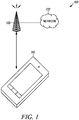
- FIG. 1 is an example block diagram of a system 100 according to a possible embodiment.
- the system 100 can include a User Equipment (UE) 110, a base station 120, such as an enhanced NodeB (eNB), an access point, or other communication station, and a network 130.
- the UE 110 can be a wireless terminal, a portable wireless communication device, a smartphone, a cellular telephone, a flip phone, a personal digital assistant, a device having a subscriber identity module, a personal computer, a selective call receiver, a tablet computer, a laptop computer, or any other device that is capable of sending and receiving communication signals on a wireless network.
- the network 130 can include any type of network that is capable of sending and receiving wireless communication signals.
- the network 130 can include a wireless communication network, a cellular telephone network, a Time Division Multiple Access (TDMA)-based network, a Code Division Multiple Access (CDMA)-based network, an Orthogonal Frequency Division Multiple Access (OFDMA)-based network, a Long Term Evolution (LTE) network, a 3rd Generation Partnership Project (3GPP)-based network, a satellite communications network, a high altitude platform network, and/or other WWAN communications networks.
- TDMA Time Division Multiple Access
- CDMA Code Division Multiple Access
- OFDMA Orthogonal Frequency Division Multiple Access
- LTE Long Term Evolution
- 3GPP 3rd Generation Partnership Project
- the UE 110 uses a Physical Uplink Control Channel (PUCCH) to carry uplink control information from the UE to the base station 110.
- PUCCH Physical Uplink Control Channel
- Embodiments can improve PUCCH performance for intra-band contiguous Carrier Aggregation (CA) and even for a single band Component Carrier (CC).
- CA Carrier Aggregation
- CC Component Carrier
- the location of the UE local oscillator is different depending on whether the UE is configured for single CC operation or for intra-band contiguous CA operation.
- the emissions requirements for the UE are defined relative to the single CC spectrum for single CC operation, and are defined relative to the spectrum of the aggregated CC's for CA operation.
- the PUCCH is sent on the primary cell (PCell). For at least these reasons, the A-MPR needed to meet emissions requirements when transmitting the PUCCH depends on whether the UE is configured for CA operation or is configured for single CC operation.
- Table 6.6.3.3.16-1 Additional requirement NS_22 Frequency band (MHz) Channel bandwidth / Spectrum emission limit (dBm) MBW 5, 10, 15, 20 MHz 3400 ⁇ f ⁇ 3800 -23 (NOTE 1, NOTE 3) 5MHz -40 (NOTE 2) 1MHz NOTE 1: This requirement applies within an offset between 5 MHz and 25 MHz from the lower and from the upper edge of the channel bandwidth, whenever these frequencies overlap with the specified frequency band. NOTE 2: This requirement applies from 3400 MHz to 25 MHz below the lower E-UTRA channel edge and from 25 MHz above the upper E-UTRA channel edge to 3800 MHz. NOTE 3: This emission limit might imply risk of harmful interference to UE(s) operating in the protected operating band.
- Table 2 CA_NS_8 Additional requirement.
- NOTE 1 This requirement applies within an offset between 5 MHz and 25 MHz from the lower and from the upper edge of the channel bandwidth.
- NOTE 2 This requirement applies from 3400 MHz to 25 MHz below the lower E-UTRA channel edge and from 25 MHz above the upper E-UTRA channel edge to 3800 MHz.
- This emission limit might imply risk of harmful interference to UE(s) operating in the protected operating band.
- the operator For a UE in single CC operation, the operator must over-provision the PUCCH by 21 RB's for no A-MPR for a 20 MHz carrier. For example, an operator can over-provision the PUCCH by shifting the PUCCH RB's inwards symmetrically from each edge of the component carrier so that the PUCCH RB's are an equal number of RB's away from each edge of a component carrier in the frequency domain. Alternatively, if the operator can accept 3 dB of A-MPR for the PUCCH and still meet coverage requirements, then no over-provisioning of the PUCCH is required for the non-CA UE.
- Table 6.2.4-17 A-MPR for "NS-22" Channel bandwidth [MHz] Parameters Region A Region B Region C Region D 20 RB start 0-35 0-51 ⁇ 21 ⁇ 31 L CRB [RBs] >64 49-64 ⁇ 48 ⁇ 48 RB start + LCRB [RBs] N/A N/A N/A ⁇ 79 A-MPR [dB] ⁇ 5 ⁇ 4 ⁇ 3 ⁇ 3 NOTE 1; RBstart indicates the lowest RB index of transmitted resource blocks. NOTE 2; LCRB is the length of a contiguous resource block allocation. NOTE 3; For intra-sub frame frequency hopping between two regions, notes 1 and 2 apply per slot basis. NOTE 4; For intra-subframe frequency hopping between two regions, the larger A-MPR value of the two regions may be applied for both slots in the subframe.
- L CRB can be a transmission bandwidth which represents the length of a contiguous resource block allocation expressed in units of resources blocks.
- RB start can indicate the lowest RB index of transmitted resource blocks.
- the operator must over-provision the PUCCH by 58 RB's for no A-MPR if CA_NS_08 is signaled, and this is not possible since a 20 MHz CC only has 100 RB's. Additionally, unless the operator over-provisions the PUCCH by at least 21 RB's, 11 dB of A-MPR will be needed to meet the CA_NS_08 emissions requirements.
- FIG. 2 is an example illustration of a graph 200 according to a possible embodiment.
- the graph 200 shows the A-MPR needed for the aggregation of two 20 MHz carriers.
- the graph 200 shows the A-MPR required to meet CA_NS_08 emissions requirements for an aggregated bandwidth of 39.8 MHz (100 RB's + 100 RB's).
- the graph 200 also shows that the UE does not need any A-MPR to meet CA_NS_08 emissions for a single RB in locations 59 to 140 (numbering is 0 to 199).
- the UE is allowed 11 dB of A-MPR for RB 0 and no A-MPR for RB 99.
- the PCell for the UE is the upper carrier and the UE PUCCH RB pair is 100 and 199, the UE is allowed 11 dB of A-MPR for RB 199 and no A-MPR for RB 100.
- a new higher power class of 26 dBm may be introduced for Band 41. If the emissions behavior is the same for this new power class power amplifier, then the A-MPR for the edge RB's (RB's 0 and 199) is likely to be at least 14 dB, while the A-MPR for the RB's nearest to the center of the aggregated spectrum (RB's 99 and 100) is likely to remain 0 dB. Thus, for the new power class, the A-MPR allowed for both PUCCH RB's (the pair 0 & 99 or the pair 100 & 199) would be 14 dB, even though no A-MPR is required for the RB of the pair that is nearest to the center of the aggregated spectrum.
- a configured maximum device output power for a serving cell (P CMAX_L ) for carrier aggregation
- the P CMAX_L is evaluated per slot and given by the minimum value taken over the transmission(s) within the slot; the minimum P CMAX_L over the two slots is then applied for the entire subframe.
- P PowerClass shall not be exceeded by the UE during any period of time.
- 11 dB of A-MPR will be allowed for both RB's.
- 11 dB of A-MPR will be allowed for both RB's even though no A-MPR is needed for RB 100.
- the above description illustrates two problems.
- the first problem is that the operator may have difficulty configuring the PUCCH region for contiguous carrier aggregation because the no A-MPR region will be much different for UE's configured for carrier aggregation than for UE's configured for single CC operation. As a part of this first problem, it may not be possible for the operator to configure the PUCCH region for no A-MPR for a UE configured for carrier aggregation.
- the second problem is that, for the UE configured for carrier aggregation, it will often be the case that large A-MPR is required for one RB of the PUCCH RB pair (the RB at the edge of the aggregated spectrum), while no A-MPR is required for the other RB of the PUCCH RB pair (the RB near the center of the aggregated spectrum). Because the allowed A-MPR for the subframe is the maximum of the A-MPR allowed for the two slots, very large A-MPR will be allowed (and taken) for PUCCH RB's for which no A-MPR is required.
- a UE can only transmit in the slot for the PUCCH RB for which the lower A-MPR is allowed. This can be done in the case that the allowed A-MPR difference between the two PUCCH RB's exceeds a threshold of Z dB.
- the value of Z can be set in the specification 36.101 and pre-set in memory of a UE, can be set in the specification 36.101 and signaled to the UE, such as by signaling the value of this parameter using the System Information Block (SIB) or using Radio Link Control (RLC) signaling, can be determined by a network operator and signaled to the UE, such as by using the System Information Block (SIB) or using Radio Link Control (RLC) signaling, and/or can be otherwise provided to the UE.
- SIB System Information Block
- RLC Radio Link Control
- the total PUCCH energy can be greater if the UE transmits only on the RB in the slot with lower A-MPR than if it uses the maximum of the two A-MPR values and transmits a PUCCH RB in both slots.
- This embodiment can be used only for UE's configured for contiguous carrier aggregation, or it can be used more generally for non-CA UE's in the case of asymmetric emissions requirements.
- the A-MPR difference threshold can depend on the difference in the signal-to-noise ratio needed to successfully demodulate the PUCCH transmission when it is transmitted on both PUCCH RB's and the signal-to-noise ratio needed to successfully demodulate the PUCCH transmission when it is transmitted on only one of the PUCCH RB's. If the signal transmitted on the two PUCCH RB's is the same (e.g., if the PUCCH transmission on the second PUCCH RB is a repetition of the PUCCH transmission on the first PUCCH RB), then the difference in the signal-to-noise ratio requirement may be 3 dB.
- the difference in signal-to-noise ratio for successful reception may be larger than 3 dB if different systematic and parity symbols are sent on the two PUCCH RB's.
- the A-MPR difference threshold can depend on the encoding method used for the PUCCH transmission. In some cases, the PUCCH may not be uniquely decodable from each of the two RB's separately.
- the PUCCH transmission is not uniquely decodable from each transmission separately, then it may be necessary to modify the encoding of the PUCCH when the PUCCH is transmitted on only one of the two PUCCH RB's so that the message is uniquely decodable from each PUCCH RB separately, and so that the signal-to-noise ratio required to demodulate the single RB transmission is minimized.
- FIG. 3 is an example flowchart 300 illustrating the operation of a UE, such as the UE 110, according to a possible embodiment.
- an indication of a resource allocation assignment of resource blocks for the PUCCH transmission can be received.
- information for the PUCCH assignment can be signaled to the device, such as by using Radio Link Control (RLC) signaling, using a System Information Block (SIB), or by using any other method for signaling a PUCCH.
- RLC Radio Link Control
- SIB System Information Block
- Signaling the A-MPR difference threshold may be used over the SIB rather than using RLC signaling to reduce signaling overhead since the SIB is a broadcast message that can be received by all UE's in the cell, and this is in contrast to RLC signaling which is sent to each UE separately.
- an A-MPR difference threshold can be received at the UE. Alternately, the A-MPR difference threshold can be pre-loaded in a memory of the UE, such as before the UE is sold to
- a first Additional Maximum Power Reduction (A-MPR) to apply to a transmission power for a first resource block of a PUCCH transmission can be ascertained at the UE.
- A-MPR Additional Maximum Power Reduction
- a second A-MPR to apply to a transmission power for a second resource block of a PUCCH transmission can be ascertained.
- the first and second A-MPR can be dependent on whether the device is configured for carrier aggregation or configured for a single component carrier.
- a carrier can be a bandwidth configuration used for transmission in LTE.
- a difference between the first A-MPR and the second A-MPR can be determined.
- a lower bound of a configured maximum device output power for a serving cell (P CMAX_L ) can be defined for the subframe using the slot with the lower A-MPR.
- PUCCH encoding can be modified when transmitting PUCCH in a slot of a subframe only for the PUCCH resource block of the first and second resource blocks with a lower A-MPR of the first A-MPR and the second A-MPR when a magnitude of the difference between the first A-MPR and the second A-MPR is greater than an A-MPR difference threshold.
- the PUCCH encoding can be modified to minimize the Signal-to-Interference plus Noise Ratio (SINR) needed to decode the one PUCCH resource block and also make sure that the transmission is uniquely decodable from the single resource block transmission. This modification may or may not be used and can depend on the type of PUCCH transmission.
- SINR Signal-to-Interference plus Noise Ratio
- the PUCCH transmission can be power controlled to a target power P PUCCH_TARGET.
- the decision to transmit on one or both PUCCH RB's can be made in the following manner:
- the UE when a UE configured for contiguous intra-band carrier aggregation is transmitting only on the PUCCH in a subframe, the UE is required to reconfigure for single component carrier transmission prior to transmitting the PUCCH only transmission, where the UE is reconfigured by moving the transmitter local oscillator to the center of the component carrier on which the PUCCH is being transmitted.
- the single component carrier A-MPR for the component carrier on which the PUCCH is transmitted applies when the UE is transmitting only on the PUCCH.
- the UE can be reconfigured for intra-band carrier aggregation and the contiguous intra-band carrier aggregation A-MPR applies.
- a PUCCH resource block can be transmitted in a slot of a subframe only for the PUCCH resource block of the first and second resource blocks with a lower A-MPR of the first A-MPR and the second A-MPR when a magnitude of the difference between the first A-MPR and the second A-MPR is greater than an A-MPR difference threshold.
- Transmitting can include transmitting the PUCCH resource block in the slot of a subframe only for the PUCCH resource block of the first and second resource blocks using the lower A-MPR applied to a transceiver uplink transmission power when the difference between the first A-MPR and the second A-MPR is greater than a threshold.
- the A-MPR difference threshold can be dependent on whether the device is configured for carrier aggregation or configured for a single component carrier. If there is no difference between the first A-MPR and the second A-MPR, or if the difference is less than the A-MPR difference threshold, the PUCCH can be transmitted on both the first and second resource blocks.
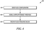
- FIG. 4 is an example flowchart 400 illustrating the operation of a base station, such as the base station 120, according to a possible embodiment.
- a PUCCH configuration can be sent, such as to the UE 110.
- Sending the PUCCH configuration can include sending an indication of a resource allocation of resource blocks for transmission of the PUCCH.
- an A-MPR difference threshold for the UE 110 can be signaled.
- the A-MPR difference threshold can be for the UE 110 to transmit in a PUCCH resource block in a slot of a subframe for the PUCCH configuration based on the A-MPR difference threshold.
- the A-MPR difference threshold can be signaled over SIB, RLC, or any other means for signaling an A-MPR difference threshold.
- the A-MPR difference threshold can indicate a threshold for the UE 110 to transmit in a slot of a subframe only for a PUCCH resource block with a lower A-MPR when a magnitude of a difference between a first A-MPR for a first PUCCH resource block and a second A-MPR for a second PUCCH resource block is greater than an A-MPR difference threshold.
- the A-MPR difference threshold can be dependent on whether the device is configured for carrier aggregation or configured for a single component carrier.
- the PUCCH resource block can be received in the slot of the subframe.
- FIG. 5 is an example block diagram of an apparatus 500, such as the UE 110, according to a possible embodiment.
- the apparatus 500 can include a housing 510, a controller 520 within the housing 510, audio input and output circuitry 530 coupled to the controller 520, a display 540 coupled to the controller 520, a transceiver 550 coupled to the controller 520, an antenna 555 coupled to the transceiver 550, a user interface 560 coupled to the controller 520, a memory 570 coupled to the controller 520, and a network interface 580 coupled to the controller 520.
- the apparatus 500 can perform the methods described in all the embodiments.
- the display 540 can be a viewfinder, a liquid crystal display (LCD), a light emitting diode (LED) display, a plasma display, a projection display, a touch screen, or any other device that displays information.
- the transceiver 550 can include a transmitter and/or a receiver.
- the audio input and output circuitry 530 can include a microphone, a speaker, a transducer, or any other audio input and output circuitry.
- the user interface 560 can include a keypad, a keyboard, buttons, a touch pad, a joystick, a touch screen display, another additional display, or any other device useful for providing an interface between a user and an electronic device.
- the network interface 580 can be a Universal Serial Bus (USB) port, an Ethernet port, an infrared transmitter/receiver, an IEEE 1394 port, a WLAN transceiver, or any other interface that can connect an apparatus to a network, device, or computer and that can transmit and receive data communication signals.
- the memory 570 can include a random access memory, a read only memory, an optical memory, a flash memory, a removable memory, a hard drive, a cache, or any other memory that can be coupled to a wireless communication device.
- the apparatus 500 or the controller 520 may implement any operating system, such as Microsoft Windows®, UNIX®, or LINUX®, AndroidTM, or any other operating system.
- Apparatus operation software may be written in any programming language, such as C, C++, Java or Visual Basic, for example.
- Apparatus software may also run on an application framework, such as, for example, a Java® framework, a .NET® framework, or any other application framework.
- the software and/or the operating system may be stored in the memory 570 or elsewhere on the apparatus 500.
- the apparatus 500 or the controller 520 may also use hardware to implement disclosed operations.
- the controller 520 may be any programmable processor.
- Disclosed embodiments may also be implemented on a general-purpose or a special purpose computer, a programmed microprocessor or microprocessor, peripheral integrated circuit elements, an application-specific integrated circuit or other integrated circuits, hardware/electronic logic circuits, such as a discrete element circuit, a programmable logic device, such as a programmable logic array, field programmable gate-array, or the like.
- the controller 520 may be any controller or processor device or devices capable of operating a wireless communication device and implementing the disclosed embodiments.
- the transceiver 550 can receive an indication of a resource allocation assignment of resource blocks for the PUCCH transmission.
- the controller 520 can ascertain a first Additional Maximum Power Reduction (A-MPR) to apply to a transmission power for a first resource block of a PUCCH transmission.
- the controller 520 can ascertain a second A-MPR to apply to a transmission power for a second resource block of a PUCCH transmission
- the controller 520 can determine a difference between the first A-MPR and the second A-MPR.
- the first and second A-MPR are dependent on whether the apparatus 500 is configured for carrier aggregation or configured for a single component carrier.
- the transceiver 550 can transmit a PUCCH resource block in a slot of a subframe only for the PUCCH resource block of the first and second resource blocks with a lower A-MPR of the first A-MPR and the second A-MPR when a magnitude of the difference between the first A-MPR and the second A-MPR is greater than an A-MPR difference threshold.
- the controller 520 to cause the transceiver to transmit the PUCCH resource block.
- the A-MPR difference threshold can be dependent on whether the apparatus is configured for carrier aggregation or configured for a single component carrier.
- the transceiver can receive the A-MPR difference threshold.
- the A-MPR difference threshold can be pre-loaded in the memory 570.
- the controller 520 can define a lower bound of a configured maximum transceiver output power for a serving cell (P CMAX_L ) for the subframe using the slot with the lower A-MPR.
- FIG. 6 is an example block diagram of a base station 600, such as the base station 120, according to a possible embodiment.
- the base station 600 may include a controller 610, a memory 620, a database interface 630, a transceiver 640, Input/Output (I/O) device interface 650, a network interface 660, and a bus 670.
- the base station 600 may implement any operating system, such as Microsoft Windows®, UNIX, or LINUX, for example.
- Base station operation software may be written in any programming language, such as C, C++, Java or Visual Basic, for example.
- the base station software may run on an application framework, such as, for example, a Java® server, a .NET® framework, or any other application framework.
- the transceiver 640 may create a data connection with the UE 110.
- the controller 610 may be any programmable processor. Disclosed embodiments may also be implemented on a general-purpose or a special purpose computer, a programmed microprocessor or microprocessor, peripheral integrated circuit elements, an application-specific integrated circuit or other integrated circuits, hardware/electronic logic circuits, such as a discrete element circuit, a programmable logic device, such as a programmable logic array, field programmable gate-array, or the like.
- the controller 610 may be any controller or processor device or devices capable of operating a base station and implementing the disclosed embodiments.
- the memory 620 may include volatile and nonvolatile data storage, including one or more electrical, magnetic, or optical memories, such as a Random Access Memory (RAM), cache, hard drive, or other memory device.
- RAM Random Access Memory
- the memory 620 may have a cache to speed access to specific data.
- the memory 620 may also be connected to a Compact Disc - Read Only Memory (CD-ROM), Digital Video Disc - Read Only memory (DVD-ROM), DVD read write input, tape drive, thumb drive, or other removable memory device that allows media content to be directly uploaded into a system.
- Data may be stored in the memory 620 or in a separate database.
- the database interface 630 may be used by the controller 610 to access the database.
- the database may contain any formatting data to connect the UE 110 to the network 130.
- the I/O device interface 650 may be connected to one or more input and output devices that may include a keyboard, a mouse, a touch screen, a monitor, a microphone, a voice-recognition device, a speaker, a printer, a disk drive, or any other device or combination of devices that accept input and/or provide output.
- the I/O device interface 650 may receive a data task or connection criteria from a network administrator.
- the network connection interface 660 may be connected to a communication device, modem, network interface card, a transceiver, or any other device capable of transmitting and receiving signals to and from the network 130.
- the components of the base station 600 may be connected via the bus 670, may be linked wirelessly, or may be otherwise connected.
- embodiments can be implemented using computer-executable instructions, such as program modules, being executed by an electronic device, such as a general purpose computer.
- program modules can include routine programs, objects, components, data structures, and other program modules that perform particular tasks or implement particular abstract data types.
- the program modules may be software-based and/or may be hardware-based.
- the program modules may be stored on computer readable storage media, such as hardware discs, flash drives, optical drives, solid state drives, CD-ROM media, thumb drives, and other computer readable storage media that provide non-transitory storage aside from a transitory propagating signal.
- embodiments may be practiced in network computing environments with many types of computer system configurations, including personal computers, hand-held devices, multi-processor systems, microprocessor-based or programmable consumer electronics, network personal computers, minicomputers, mainframe computers, and other computing environments.
- the base station 600 can perform operation described in the embodiments.
- the controller 610 can cause the transceiver 640 to send a PUCCH configuration and signal an A-MPR difference threshold for a device to transmit in a PUCCH resource block in a slot of a subframe for the PUCCH configuration based on the A-MPR difference threshold.
- the transceiver 640 can receive the PUCCH resource block in the slot of the subframe.
- A-MPR can be defined independently for the first and second slots.
- the UE configured for carrier aggregation can be allowed different A-MPR for the first and second slots of the PUCCH transmission.
- CA_NS_08 this can often mean the CA UE can be allowed more A-MPR than the single CC UE for the PUCCH RB nearest to the edge of the aggregated spectrum, but the CA UE can be allowed less A-MPR than the single CC UE for the PUCCH RB nearest to the center of the aggregated spectrum.
- This embodiment may have the UE to change power between slots. Because the UE can change RB's between first and second subframes, there can be an allowed transition period between the first and second slots. Just as the RB changes during this transition period, the power level can also be changed during this transition period.
- FIG. 7 is an example illustration of a transmission power template 700 according to a possible embodiment.
- the sub frame boundary time mask defines the observation period between the previous/subsequent sub-frame and the (reference) sub-frame.
- a transient period at a slot boundary within a sub-frame is only allowed in the case of Intra-sub-frame frequency hopping.
- the time masks in sub clause 6.3.4.4 can apply.
- Changing the transmission RB's from the first slot to the second slot can be considered frequency hopping so that it is covered by the transmission power template 700 below and there can be an allowed transition period.
- the specification the transmission power template 700 and description can change so that it does allow a transition period during which the power can be changed.
- the definition of P CMAX_L for carrier aggregation in Section 6.2.5A of 36.101 indicates that for each subframe, the P CMAX_L is evaluated per slot and given by the minimum value taken over the transmission(s) within the slot; the minimum P CMAX_L over the two slots is then applied for the entire subframe.
- P PowerClass shall not be exceeded by the UE during any period of time.
- a new definition can indicate that for subframes containing only PUCCH transmissions, P CMAX_L is defined independently for the two slots, and the minimum is not used for the entire subframe.
- the A-MPR at the center of the aggregated spectrum can be very small or zero for the UE configured for CA.
- the PUCCH can be provisioned for the single CC UE (same PUCCH provisioning can be used for both types of users) and allow the CA UE to transmit only on the PUCCH RB with small or 0 dB of A-MPR.
- the CA UE is expected to transmit on both PUCCH RB's and is allowed to use the max A-MPR for these two RB's for both PUCCH transmissions.
- This approach may be used only if the difference in A-MPR between the two PUCCH RB's is very large.
- the difference value can be signalled by the operator either using the SIB or via RLC signalling. If a high power UE is allowed (26 dB), the A-MPR difference between the two PUCCH RB's may be increased by 3 dB relative to the already large A-MPR difference for the 23 dBm power class.
- the method of this disclosure can be implemented on a programmed processor.
- the controllers, flowcharts, and modules may also be implemented on a general purpose or special purpose computer, a programmed microprocessor or microcontroller and peripheral integrated circuit elements, an integrated circuit, a hardware electronic or logic circuit such as a discrete element circuit, a programmable logic device, or the like.
- any device on which resides a finite state machine capable of implementing the flowcharts shown in the figures may be used to implement the processor functions of this disclosure.
Landscapes
- Engineering & Computer Science (AREA)
- Computer Networks & Wireless Communication (AREA)
- Signal Processing (AREA)
- Mobile Radio Communication Systems (AREA)
Abstract
Description
- The present disclosure is directed to a method and apparatus for transmitting a Physical Uplink Control Channel (PUCCH) with a lower Additional Maximum Power Reduction (A-MPR).
- Presently, wireless communication devices, otherwise known as User Equipment (UE), such as smartphones, laptop computers, wireless terminals, and other wireless communication devices, communicate with other communication devices using wireless signals. To communicate over a wireless network, the wireless communication devices use control channels to signal channel information. For example, a Physical Uplink Control Channel (PUCCH) is used to carry uplink control information from a wireless communication device to a wireless communication station, such as a base station, an enhanced NodeB (eNB), an access point, or other wireless communication station that connects the wireless communication device with at least one network, the Internet, and other communication devices.
- There is a problem with PUCCH operation for a network supporting intra-band contiguous Carrier Aggregation (CA) where more than one carrier is aggregated together in a contiguous frequency spectrum to increase data throughput. When transmitting on an uplink to a base station, a UE uses an Additional Maximum Power Reduction (A-MPR) to reduce the allowed minimum value of its maximum output power. Different regions in the transmission spectrum provide for different A-MPR. The issue is that that a 0 dB A-MPR region, such as a low A-MPR region, is different depending on whether the UE is configured for single Component Carrier (CC) operation or if the UE is configured for CA. As a consequence, a network operator may not be able to over-provision the PUCCH region, such as reassign the Resource Blocks (RB's) allocated for the PUCCH region, enough to allow 0 dB of A-MPR for a UE configured for CA. Furthermore, the A-MPR for Resource Blocks (RB's) in the PUCCH may be very asymmetric, with the RB nearest to the edge of the aggregated spectrum requiring very large A-MPR while the RB near the center of the aggregated spectrum may require no A-MPR at all. With the current specification, both RB's are allowed to use the maximum of the two A-MPR values.
- As mentioned above, the existing solution for single CC is to over-provision the PUCCH, such as adjust the PUCCH region, so that the PUCCH RB pair is in a frequency region with 0 or small A-MPR. For a UE configured for CA, it will not in general be possible to over-provision the PUCCH sufficiently to have 0 dB A-MPR since the location of the UE local oscillator is in the middle of the aggregated spectrum. Furthermore, the operator may not wish to configure the PUCCH region for the needs of the CA UE over the needs of the non-CA UE's.
- Thus, there is a need for a method and apparatus for transmitting a PUCCH with a lower A-MPR.
- In order to describe the manner in which advantages and features of the disclosure can be obtained, a description of the disclosure is rendered by reference to specific embodiments thereof which are illustrated in the appended drawings. These drawings depict only example embodiments of the disclosure and are not therefore to be considered to be limiting of its scope.
-
FIG. 1 is an example block diagram of a system according to a possible embodiment; -
FIG. 2 is an example illustration of a graph according to a possible embodiment; -
FIG. 3 is an example flowchart illustrating the operation of a user equipment according to a possible embodiment; -
FIG. 4 is an example flowchart illustrating the operation of a base station according to a possible embodiment; -
FIG. 5 is an example block diagram of an apparatus according to a possible embodiment; -
FIG. 6 is an example block diagram of a base station according to a possible embodiment; and -
FIG. 7 is an example illustration of atransmission power template 700 according to a possible embodiment. - Embodiments provide a method and apparatus for transmitting a Physical Uplink Control Channel (PUCCH) with a lower Additional Maximum Power Reduction (A-MPR). According to a possible embodiment, a first A-MPR to apply to a transmission power can be ascertained at a device for a first resource block of a PUCCH transmission. A second A-MPR to apply to a transmission power can be ascertained for a second resource block of a PUCCH transmission. A difference between the first A-MPR and the second A-MPR can be determined. A PUCCH resource block can be transmitted in a slot of a subframe only for the PUCCH resource block of the first and second resource blocks with a lower A-MPR of the first A-MPR and the second A-MPR when a magnitude of the difference between the first A-MPR and the second A-MPR is greater than an A-MPR difference threshold.
-
FIG. 1 is an example block diagram of asystem 100 according to a possible embodiment. Thesystem 100 can include a User Equipment (UE) 110, abase station 120, such as an enhanced NodeB (eNB), an access point, or other communication station, and anetwork 130. The UE 110 can be a wireless terminal, a portable wireless communication device, a smartphone, a cellular telephone, a flip phone, a personal digital assistant, a device having a subscriber identity module, a personal computer, a selective call receiver, a tablet computer, a laptop computer, or any other device that is capable of sending and receiving communication signals on a wireless network. - The
network 130 can include any type of network that is capable of sending and receiving wireless communication signals. For example, thenetwork 130 can include a wireless communication network, a cellular telephone network, a Time Division Multiple Access (TDMA)-based network, a Code Division Multiple Access (CDMA)-based network, an Orthogonal Frequency Division Multiple Access (OFDMA)-based network, a Long Term Evolution (LTE) network, a 3rd Generation Partnership Project (3GPP)-based network, a satellite communications network, a high altitude platform network, and/or other WWAN communications networks. - In operation, the UE 110 uses a Physical Uplink Control Channel (PUCCH) to carry uplink control information from the UE to the
base station 110. Embodiments can improve PUCCH performance for intra-band contiguous Carrier Aggregation (CA) and even for a single band Component Carrier (CC). For example, there is a problem with PUCCH operation for a network supporting intra-band contiguous CA. The issue is that that the low A-MPR region, such as the 0 dB A-MPR region, is different depending on whether the UE is configured for single CC operation or if the UE is configured for CA. One reason for the difference is that the location of the UE local oscillator is different depending on whether the UE is configured for single CC operation or for intra-band contiguous CA operation. Another reason for the difference is that the emissions requirements for the UE are defined relative to the single CC spectrum for single CC operation, and are defined relative to the spectrum of the aggregated CC's for CA operation. Additionally, even when the UE is configured for CA operation, the PUCCH is sent on the primary cell (PCell). For at least these reasons, the A-MPR needed to meet emissions requirements when transmitting the PUCCH depends on whether the UE is configured for CA operation or is configured for single CC operation.
Consider the example of Band 42 for which a network signaling value NS_22 that signals additional spurious emissions requirements for a specific deployment scenario as shown in the 3GPP LTE specification Table 6.6.3.3.16-1 below is signaled for a single CC UE, and a carrier aggregation network signaling value CA_NS_08 that signals additional spurious emissions requirements for a specific deployment scenario as shown in Table 2 below is signaled for a CA UE. Note that the same emission requirements apply for both NS_22 and CA_NS_08.Table 6.6.3.3.16-1: Additional requirement NS_22 Frequency band (MHz) Channel bandwidth / Spectrum emission limit (dBm) MBW 5, 10, 15, 20 MHz 3400 ≤ f ≤ 3800 -23 ( NOTE 1, NOTE 3)5MHz -40 (NOTE 2) 1MHz NOTE 1: This requirement applies within an offset between 5 MHz and 25 MHz from the lower and from the upper edge of the channel bandwidth, whenever these frequencies overlap with the specified frequency band. NOTE 2: This requirement applies from 3400 MHz to 25 MHz below the lower E-UTRA channel edge and from 25 MHz above the upper E-UTRA channel edge to 3800 MHz. NOTE 3: This emission limit might imply risk of harmful interference to UE(s) operating in the protected operating band. Table 2: CA_NS_8 Additional requirement. Frequency band (MHz) Channel bandwidth / Spectrum emission limit (dBm) MBW 3400 ≤ f ≤ 3800 -23 ( NOTE 1, NOTE 3)5MHz -40 (NOTE 2) 1MHz NOTE 1: This requirement applies within an offset between 5 MHz and 25 MHz from the lower and from the upper edge of the channel bandwidth. NOTE 2: This requirement applies from 3400 MHz to 25 MHz below the lower E-UTRA channel edge and from 25 MHz above the upper E-UTRA channel edge to 3800 MHz. NOTE 3: This emission limit might imply risk of harmful interference to UE(s) operating in the protected operating band. - For a UE in single CC operation, the operator must over-provision the PUCCH by 21 RB's for no A-MPR for a 20 MHz carrier. For example, an operator can over-provision the PUCCH by shifting the PUCCH RB's inwards symmetrically from each edge of the component carrier so that the PUCCH RB's are an equal number of RB's away from each edge of a component carrier in the frequency domain. Alternatively, if the operator can accept 3 dB of A-MPR for the PUCCH and still meet coverage requirements, then no over-provisioning of the PUCCH is required for the non-CA UE.
Table 6.2.4-17: A-MPR for "NS-22" Channel bandwidth [MHz] Parameters Region A Region B Region C Region D 20 RBstart 0-35 0-51 ≤ 21 ≥ 31 LCRB [RBs] >64 49-64 ≤ 48 ≤ 48 RBstart + LCRB [RBs] N/A N/A N/A ≥ 79 A-MPR [dB] ≤ 5 ≤ 4 ≤ 3 ≤ 3 NOTE 1; RBstart indicates the lowest RB index of transmitted resource blocks.NOTE 2; LCRB is the length of a contiguous resource block allocation.NOTE 3; For intra-sub frame frequency hopping between two regions,notes NOTE 4; For intra-subframe frequency hopping between two regions, the larger A-MPR value of the two regions may be applied for both slots in the subframe. - In the 3GPP LTE specification Table 6.2.4-17 above, LCRB can be a transmission bandwidth which represents the length of a contiguous resource block allocation expressed in units of resources blocks. Also, RBstart can indicate the lowest RB index of transmitted resource blocks.
- Conversely, for a UE configured for CA of two 20 MHz carriers, the operator must over-provision the PUCCH by 58 RB's for no A-MPR if CA_NS_08 is signaled, and this is not possible since a 20 MHz CC only has 100 RB's. Additionally, unless the operator over-provisions the PUCCH by at least 21 RB's, 11 dB of A-MPR will be needed to meet the CA_NS_08 emissions requirements.
-
FIG. 2 is an example illustration of agraph 200 according to a possible embodiment. Thegraph 200 shows the A-MPR needed for the aggregation of two 20 MHz carriers. For example, thegraph 200 shows the A-MPR required to meet CA_NS_08 emissions requirements for an aggregated bandwidth of 39.8 MHz (100 RB's + 100 RB's). Thegraph 200 also shows that the UE does not need any A-MPR to meet CA_NS_08 emissions for a single RB in locations 59 to 140 (numbering is 0 to 199). Thus, if the PCell for the UE is the lower carrier and the UE PUCCH RB pair is 0 and 99, the UE is allowed 11 dB of A-MPR forRB 0 and no A-MPR for RB 99. Similarly, if the PCell for the UE is the upper carrier and the UE PUCCH RB pair is 100 and 199, the UE is allowed 11 dB of A-MPR for RB 199 and no A-MPR forRB 100. - A new higher power class of 26 dBm may be introduced for Band 41. If the emissions behavior is the same for this new power class power amplifier, then the A-MPR for the edge RB's (RB's 0 and 199) is likely to be at least 14 dB, while the A-MPR for the RB's nearest to the center of the aggregated spectrum (RB's 99 and 100) is likely to remain 0 dB. Thus, for the new power class, the A-MPR allowed for both PUCCH RB's (the
pair 0 & 99 or thepair 100 & 199) would be 14 dB, even though no A-MPR is required for the RB of the pair that is nearest to the center of the aggregated spectrum. - According to the definition of a configured maximum device output power for a serving cell (PCMAX_L) for carrier aggregation, for each subframe, the PCMAX_L is evaluated per slot and given by the minimum value taken over the transmission(s) within the slot; the minimum PCMAX_L over the two slots is then applied for the entire subframe. PPowerClass shall not be exceeded by the UE during any period of time. Thus, even though no A-MPR is needed for RB 99 for the PUCCH pairing of RB's 0 and 99, 11 dB of A-MPR will be allowed for both RB's. Similarly, for the PUCCH pairing of RB's 100 and 199, 11 dB of A-MPR will be allowed for both RB's even though no A-MPR is needed for
RB 100. - The above description illustrates two problems. The first problem is that the operator may have difficulty configuring the PUCCH region for contiguous carrier aggregation because the no A-MPR region will be much different for UE's configured for carrier aggregation than for UE's configured for single CC operation. As a part of this first problem, it may not be possible for the operator to configure the PUCCH region for no A-MPR for a UE configured for carrier aggregation. The second problem is that, for the UE configured for carrier aggregation, it will often be the case that large A-MPR is required for one RB of the PUCCH RB pair (the RB at the edge of the aggregated spectrum), while no A-MPR is required for the other RB of the PUCCH RB pair (the RB near the center of the aggregated spectrum). Because the allowed A-MPR for the subframe is the maximum of the A-MPR allowed for the two slots, very large A-MPR will be allowed (and taken) for PUCCH RB's for which no A-MPR is required.
- According to a possible embodiment, a UE can only transmit in the slot for the PUCCH RB for which the lower A-MPR is allowed. This can be done in the case that the allowed A-MPR difference between the two PUCCH RB's exceeds a threshold of Z dB. The value of Z can be set in the specification 36.101 and pre-set in memory of a UE, can be set in the specification 36.101 and signaled to the UE, such as by signaling the value of this parameter using the System Information Block (SIB) or using Radio Link Control (RLC) signaling, can be determined by a network operator and signaled to the UE, such as by using the System Information Block (SIB) or using Radio Link Control (RLC) signaling, and/or can be otherwise provided to the UE. If the A-MPR difference exceeds 3 dB, the total PUCCH energy can be greater if the UE transmits only on the RB in the slot with lower A-MPR than if it uses the maximum of the two A-MPR values and transmits a PUCCH RB in both slots. For example, the UE can be required to transmit only on the PUCCH RB with lower allowed A-MPR in the case that the A-MPR difference for the two PUCCH RB's exceeds 4 dB (Z = 4). This embodiment can be used only for UE's configured for contiguous carrier aggregation, or it can be used more generally for non-CA UE's in the case of asymmetric emissions requirements.
- The A-MPR difference threshold can depend on the difference in the signal-to-noise ratio needed to successfully demodulate the PUCCH transmission when it is transmitted on both PUCCH RB's and the signal-to-noise ratio needed to successfully demodulate the PUCCH transmission when it is transmitted on only one of the PUCCH RB's. If the signal transmitted on the two PUCCH RB's is the same (e.g., if the PUCCH transmission on the second PUCCH RB is a repetition of the PUCCH transmission on the first PUCCH RB), then the difference in the signal-to-noise ratio requirement may be 3 dB. However, the difference in signal-to-noise ratio for successful reception may be larger than 3 dB if different systematic and parity symbols are sent on the two PUCCH RB's. In general, the A-MPR difference threshold can depend on the encoding method used for the PUCCH transmission. In some cases, the PUCCH may not be uniquely decodable from each of the two RB's separately. If the PUCCH transmission is not uniquely decodable from each transmission separately, then it may be necessary to modify the encoding of the PUCCH when the PUCCH is transmitted on only one of the two PUCCH RB's so that the message is uniquely decodable from each PUCCH RB separately, and so that the signal-to-noise ratio required to demodulate the single RB transmission is minimized.
-
FIG. 3 is anexample flowchart 300 illustrating the operation of a UE, such as theUE 110, according to a possible embodiment. At 310, an indication of a resource allocation assignment of resource blocks for the PUCCH transmission can be received. According to a possible implementation, information for the PUCCH assignment can be signaled to the device, such as by using Radio Link Control (RLC) signaling, using a System Information Block (SIB), or by using any other method for signaling a PUCCH. Signaling the A-MPR difference threshold may be used over the SIB rather than using RLC signaling to reduce signaling overhead since the SIB is a broadcast message that can be received by all UE's in the cell, and this is in contrast to RLC signaling which is sent to each UE separately. At 320, an A-MPR difference threshold can be received at the UE. Alternately, the A-MPR difference threshold can be pre-loaded in a memory of the UE, such as before the UE is sold to a consumer. - At 330, a first Additional Maximum Power Reduction (A-MPR) to apply to a transmission power for a first resource block of a PUCCH transmission can be ascertained at the UE. At 340, a second A-MPR to apply to a transmission power for a second resource block of a PUCCH transmission can be ascertained. The first and second A-MPR can be dependent on whether the device is configured for carrier aggregation or configured for a single component carrier. A carrier can be a bandwidth configuration used for transmission in LTE. At 350, a difference between the first A-MPR and the second A-MPR can be determined. At 360, a lower bound of a configured maximum device output power for a serving cell (PCMAX_L) can be defined for the subframe using the slot with the lower A-MPR.
- At 370, PUCCH encoding can be modified when transmitting PUCCH in a slot of a subframe only for the PUCCH resource block of the first and second resource blocks with a lower A-MPR of the first A-MPR and the second A-MPR when a magnitude of the difference between the first A-MPR and the second A-MPR is greater than an A-MPR difference threshold. For example, the PUCCH encoding can be modified to minimize the Signal-to-Interference plus Noise Ratio (SINR) needed to decode the one PUCCH resource block and also make sure that the transmission is uniquely decodable from the single resource block transmission. This modification may or may not be used and can depend on the type of PUCCH transmission.
- For example, according to a possible embodiment, the PUCCH transmission can be power controlled to a target power PPUCCH_TARGET. In this embodiment, the decision to transmit on one or both PUCCH RB's can be made in the following manner:
- i) The UE can first compute PCMAX_L for each slot separately to get values PCMAX_L1 and PCMAX_L2, respectively for the first and second slots, where PCMAX_L1 can depend on the PUCCH RB for the first slot and PCMAX_L2 can depend on the PUCCH RB for the second slot.
- ii) The UE can then compute two values Delta_slot1 and Delta_slot2 by subtracting PPUCCH_TARGET from PCMAX_L1 and PCMAX_L2, respectively, so that


- iii) If Delta_slot1 and Delta_slot2 are both greater than or equal to 0, then the UE can transmit on the PUCCH RB in each slot.
- iv) If at least one of Delta_slot1 and Delta_slot1 is less than 0, and if the difference max(Delta_slot1, Delta_slot2) - min(Delta_slot1, Delta_slot2) is less than the A-MPR difference threshold, then the UE can transmit on the PUCCH RB in each slot.
- v) If at least one of Delta_slot1 and Delta_slot1 is less than 0, and if the difference max(Delta_slot1, Delta_slot2) - min(Delta_slot1, Delta_slot2) exceeds the A-MPR difference threshold, then the UE can transmit only in the slot i with the lower A-MPR. The transmit power in this slot can be set equal to the min(PCMAX_Li, PPUCCH_TARGET + A-MPR difference threshold), where PCMAX_Li can be PCMAX_L for the slot with the lower A-MPR. The coding of the PUCCH may be modified when it is transmitted on only one of the two PUCCH RB's in order to minimize the signal-to-noise ratio needed to decode the PUCCH transmission and to ensure the PUCCH transmission is uniquely decodable.
- In another embodiment, when a UE configured for contiguous intra-band carrier aggregation is transmitting only on the PUCCH in a subframe, the UE is required to reconfigure for single component carrier transmission prior to transmitting the PUCCH only transmission, where the UE is reconfigured by moving the transmitter local oscillator to the center of the component carrier on which the PUCCH is being transmitted. In this embodiment, the single component carrier A-MPR for the component carrier on which the PUCCH is transmitted applies when the UE is transmitting only on the PUCCH. When not transmitting only on the PUCCH, the UE can be reconfigured for intra-band carrier aggregation and the contiguous intra-band carrier aggregation A-MPR applies.
- At 380, a PUCCH resource block can be transmitted in a slot of a subframe only for the PUCCH resource block of the first and second resource blocks with a lower A-MPR of the first A-MPR and the second A-MPR when a magnitude of the difference between the first A-MPR and the second A-MPR is greater than an A-MPR difference threshold. Transmitting can include transmitting the PUCCH resource block in the slot of a subframe only for the PUCCH resource block of the first and second resource blocks using the lower A-MPR applied to a transceiver uplink transmission power when the difference between the first A-MPR and the second A-MPR is greater than a threshold. The A-MPR difference threshold can be dependent on whether the device is configured for carrier aggregation or configured for a single component carrier. If there is no difference between the first A-MPR and the second A-MPR, or if the difference is less than the A-MPR difference threshold, the PUCCH can be transmitted on both the first and second resource blocks.
-
FIG. 4 is anexample flowchart 400 illustrating the operation of a base station, such as thebase station 120, according to a possible embodiment. At 410, a PUCCH configuration can be sent, such as to theUE 110. Sending the PUCCH configuration can include sending an indication of a resource allocation of resource blocks for transmission of the PUCCH. At 420, an A-MPR difference threshold for theUE 110 can be signaled. The A-MPR difference threshold can be for theUE 110 to transmit in a PUCCH resource block in a slot of a subframe for the PUCCH configuration based on the A-MPR difference threshold. The A-MPR difference threshold can be signaled over SIB, RLC, or any other means for signaling an A-MPR difference threshold. The A-MPR difference threshold can indicate a threshold for theUE 110 to transmit in a slot of a subframe only for a PUCCH resource block with a lower A-MPR when a magnitude of a difference between a first A-MPR for a first PUCCH resource block and a second A-MPR for a second PUCCH resource block is greater than an A-MPR difference threshold. The A-MPR difference threshold can be dependent on whether the device is configured for carrier aggregation or configured for a single component carrier. At 430, the PUCCH resource block can be received in the slot of the subframe. - It should be understood that, notwithstanding the particular steps as shown in the figures, a variety of additional or different steps can be performed depending upon the embodiment, and one or more of the particular steps can be rearranged, repeated or eliminated entirely depending upon the embodiment. Also, some of the steps performed can be repeated on an ongoing or continuous basis simultaneously while other steps are performed. Furthermore, different steps can be performed by different elements or in a single element of the disclosed embodiments.
-
FIG. 5 is an example block diagram of anapparatus 500, such as theUE 110, according to a possible embodiment. Theapparatus 500 can include ahousing 510, acontroller 520 within thehousing 510, audio input andoutput circuitry 530 coupled to thecontroller 520, adisplay 540 coupled to thecontroller 520, atransceiver 550 coupled to thecontroller 520, anantenna 555 coupled to thetransceiver 550, auser interface 560 coupled to thecontroller 520, amemory 570 coupled to thecontroller 520, and anetwork interface 580 coupled to thecontroller 520. Theapparatus 500 can perform the methods described in all the embodiments. - The
display 540 can be a viewfinder, a liquid crystal display (LCD), a light emitting diode (LED) display, a plasma display, a projection display, a touch screen, or any other device that displays information. Thetransceiver 550 can include a transmitter and/or a receiver. The audio input andoutput circuitry 530 can include a microphone, a speaker, a transducer, or any other audio input and output circuitry. Theuser interface 560 can include a keypad, a keyboard, buttons, a touch pad, a joystick, a touch screen display, another additional display, or any other device useful for providing an interface between a user and an electronic device. Thenetwork interface 580 can be a Universal Serial Bus (USB) port, an Ethernet port, an infrared transmitter/receiver, an IEEE 1394 port, a WLAN transceiver, or any other interface that can connect an apparatus to a network, device, or computer and that can transmit and receive data communication signals. Thememory 570 can include a random access memory, a read only memory, an optical memory, a flash memory, a removable memory, a hard drive, a cache, or any other memory that can be coupled to a wireless communication device. - The
apparatus 500 or thecontroller 520 may implement any operating system, such as Microsoft Windows®, UNIX®, or LINUX®, Android™, or any other operating system. Apparatus operation software may be written in any programming language, such as C, C++, Java or Visual Basic, for example. Apparatus software may also run on an application framework, such as, for example, a Java® framework, a .NET® framework, or any other application framework. The software and/or the operating system may be stored in thememory 570 or elsewhere on theapparatus 500. Theapparatus 500 or thecontroller 520 may also use hardware to implement disclosed operations. For example, thecontroller 520 may be any programmable processor. Disclosed embodiments may also be implemented on a general-purpose or a special purpose computer, a programmed microprocessor or microprocessor, peripheral integrated circuit elements, an application-specific integrated circuit or other integrated circuits, hardware/electronic logic circuits, such as a discrete element circuit, a programmable logic device, such as a programmable logic array, field programmable gate-array, or the like. In general, thecontroller 520 may be any controller or processor device or devices capable of operating a wireless communication device and implementing the disclosed embodiments. - In operation, the
transceiver 550 can receive an indication of a resource allocation assignment of resource blocks for the PUCCH transmission. Thecontroller 520 can ascertain a first Additional Maximum Power Reduction (A-MPR) to apply to a transmission power for a first resource block of a PUCCH transmission. Thecontroller 520 can ascertain a second A-MPR to apply to a transmission power for a second resource block of a PUCCH transmission - The
controller 520 can determine a difference between the first A-MPR and the second A-MPR. The first and second A-MPR are dependent on whether theapparatus 500 is configured for carrier aggregation or configured for a single component carrier. Thetransceiver 550 can transmit a PUCCH resource block in a slot of a subframe only for the PUCCH resource block of the first and second resource blocks with a lower A-MPR of the first A-MPR and the second A-MPR when a magnitude of the difference between the first A-MPR and the second A-MPR is greater than an A-MPR difference threshold. Thecontroller 520 to cause the transceiver to transmit the PUCCH resource block. The A-MPR difference threshold can be dependent on whether the apparatus is configured for carrier aggregation or configured for a single component carrier. According to a possible implementation, the transceiver can receive the A-MPR difference threshold. According to another possible implementation, the A-MPR difference threshold can be pre-loaded in thememory 570. According to a further possible implementation, thecontroller 520 can define a lower bound of a configured maximum transceiver output power for a serving cell (PCMAX_L) for the subframe using the slot with the lower A-MPR. -
FIG. 6 is an example block diagram of abase station 600, such as thebase station 120, according to a possible embodiment. Thebase station 600 may include acontroller 610, amemory 620, adatabase interface 630, atransceiver 640, Input/Output (I/O)device interface 650, anetwork interface 660, and abus 670. Thebase station 600 may implement any operating system, such as Microsoft Windows®, UNIX, or LINUX, for example. Base station operation software may be written in any programming language, such as C, C++, Java or Visual Basic, for example. The base station software may run on an application framework, such as, for example, a Java® server, a .NET® framework, or any other application framework. - The
transceiver 640 may create a data connection with theUE 110. Thecontroller 610 may be any programmable processor. Disclosed embodiments may also be implemented on a general-purpose or a special purpose computer, a programmed microprocessor or microprocessor, peripheral integrated circuit elements, an application-specific integrated circuit or other integrated circuits, hardware/electronic logic circuits, such as a discrete element circuit, a programmable logic device, such as a programmable logic array, field programmable gate-array, or the like. In general, thecontroller 610 may be any controller or processor device or devices capable of operating a base station and implementing the disclosed embodiments. - The
memory 620 may include volatile and nonvolatile data storage, including one or more electrical, magnetic, or optical memories, such as a Random Access Memory (RAM), cache, hard drive, or other memory device. Thememory 620 may have a cache to speed access to specific data. Thememory 620 may also be connected to a Compact Disc - Read Only Memory (CD-ROM), Digital Video Disc - Read Only memory (DVD-ROM), DVD read write input, tape drive, thumb drive, or other removable memory device that allows media content to be directly uploaded into a system. Data may be stored in thememory 620 or in a separate database. For example, thedatabase interface 630 may be used by thecontroller 610 to access the database. The database may contain any formatting data to connect theUE 110 to thenetwork 130. - The I/
O device interface 650 may be connected to one or more input and output devices that may include a keyboard, a mouse, a touch screen, a monitor, a microphone, a voice-recognition device, a speaker, a printer, a disk drive, or any other device or combination of devices that accept input and/or provide output. The I/O device interface 650 may receive a data task or connection criteria from a network administrator. Thenetwork connection interface 660 may be connected to a communication device, modem, network interface card, a transceiver, or any other device capable of transmitting and receiving signals to and from thenetwork 130. The components of thebase station 600 may be connected via thebus 670, may be linked wirelessly, or may be otherwise connected. - Although not required, embodiments can be implemented using computer-executable instructions, such as program modules, being executed by an electronic device, such as a general purpose computer. Generally, program modules can include routine programs, objects, components, data structures, and other program modules that perform particular tasks or implement particular abstract data types. The program modules may be software-based and/or may be hardware-based. For example, the program modules may be stored on computer readable storage media, such as hardware discs, flash drives, optical drives, solid state drives, CD-ROM media, thumb drives, and other computer readable storage media that provide non-transitory storage aside from a transitory propagating signal. Moreover, embodiments may be practiced in network computing environments with many types of computer system configurations, including personal computers, hand-held devices, multi-processor systems, microprocessor-based or programmable consumer electronics, network personal computers, minicomputers, mainframe computers, and other computing environments.
- In operation, the
base station 600 can perform operation described in the embodiments. For example, thecontroller 610 can cause thetransceiver 640 to send a PUCCH configuration and signal an A-MPR difference threshold for a device to transmit in a PUCCH resource block in a slot of a subframe for the PUCCH configuration based on the A-MPR difference threshold. Thetransceiver 640 can receive the PUCCH resource block in the slot of the subframe. - According to another possible embodiment, for a UE configured for carrier aggregation, A-MPR can be defined independently for the first and second slots. Thus, the UE configured for carrier aggregation can be allowed different A-MPR for the first and second slots of the PUCCH transmission. In the case of CA_NS_08, this can often mean the CA UE can be allowed more A-MPR than the single CC UE for the PUCCH RB nearest to the edge of the aggregated spectrum, but the CA UE can be allowed less A-MPR than the single CC UE for the PUCCH RB nearest to the center of the aggregated spectrum. This embodiment may have the UE to change power between slots. Because the UE can change RB's between first and second subframes, there can be an allowed transition period between the first and second slots. Just as the RB changes during this transition period, the power level can also be changed during this transition period.
-
FIG. 7 is an example illustration of atransmission power template 700 according to a possible embodiment. According to Section 6.3.4.3 of LTE standard 36.101, the sub frame boundary time mask defines the observation period between the previous/subsequent sub-frame and the (reference) sub-frame. A transient period at a slot boundary within a sub-frame is only allowed in the case of Intra-sub-frame frequency hopping. For the cases when the subframe contains SRS the time masks in sub clause 6.3.4.4 can apply. - Changing the transmission RB's from the first slot to the second slot can be considered frequency hopping so that it is covered by the
transmission power template 700 below and there can be an allowed transition period. Alternately, the specification thetransmission power template 700 and description can change so that it does allow a transition period during which the power can be changed. Also, the definition of PCMAX_L for carrier aggregation in Section 6.2.5A of 36.101 indicates that for each subframe, the PCMAX_L is evaluated per slot and given by the minimum value taken over the transmission(s) within the slot; the minimum PCMAX_L over the two slots is then applied for the entire subframe. PPowerClass shall not be exceeded by the UE during any period of time. A new definition can indicate that for subframes containing only PUCCH transmissions, PCMAX_L is defined independently for the two slots, and the minimum is not used for the entire subframe. - Since the emissions requirements for CA are defined relative to the aggregated spectrum, the A-MPR at the center of the aggregated spectrum can be very small or zero for the UE configured for CA. Rather than massively over-provision the PUCCH to help the CA UE's so that the A-MPR is small for the PUCCH RB nearest to the edge of the aggregated spectrum, the PUCCH can be provisioned for the single CC UE (same PUCCH provisioning can be used for both types of users) and allow the CA UE to transmit only on the PUCCH RB with small or 0 dB of A-MPR. Currently, the CA UE is expected to transmit on both PUCCH RB's and is allowed to use the max A-MPR for these two RB's for both PUCCH transmissions. This approach may be used only if the difference in A-MPR between the two PUCCH RB's is very large. The difference value can be signalled by the operator either using the SIB or via RLC signalling. If a high power UE is allowed (26 dB), the A-MPR difference between the two PUCCH RB's may be increased by 3 dB relative to the already large A-MPR difference for the 23 dBm power class.
- The method of this disclosure can be implemented on a programmed processor. However, the controllers, flowcharts, and modules may also be implemented on a general purpose or special purpose computer, a programmed microprocessor or microcontroller and peripheral integrated circuit elements, an integrated circuit, a hardware electronic or logic circuit such as a discrete element circuit, a programmable logic device, or the like. In general, any device on which resides a finite state machine capable of implementing the flowcharts shown in the figures may be used to implement the processor functions of this disclosure.
- While this disclosure has been described with specific embodiments thereof, it is evident that many alternatives, modifications, and variations will be apparent to those skilled in the art. For example, various components of the embodiments may be interchanged, added, or substituted in the other embodiments. Also, all of the elements of each figure are not necessary for operation of the disclosed embodiments. For example, one of ordinary skill in the art of the disclosed embodiments would be enabled to make and use the teachings of the disclosure by simply employing the elements of the independent claims. Accordingly, embodiments of the disclosure as set forth herein are intended to be illustrative, not limiting. Various changes may be made without departing from the spirit and scope of the disclosure.
- In this document, relational terms such as "first," "second," and the like may be used solely to distinguish one entity or action from another entity or action without necessarily requiring or implying any actual such relationship or order between such entities or actions. The phrase "at least one of" or "at least one selected from the group of" followed by a list is defined to mean one, some, or all, but not necessarily all of, the elements in the list. The terms "comprises," "comprising," or any other variation thereof, are intended to cover a non-exclusive inclusion, such that a process, method, article, or apparatus that comprises a list of elements does not include only those elements but may include other elements not expressly listed or inherent to such process, method, article, or apparatus. An element proceeded by "a," "an," or the like does not, without more constraints, preclude the existence of additional identical elements in the process, method, article, or apparatus that comprises the element. Also, the term "another" is defined as at least a second or more. The terms "including," "having," and the like, as used herein, are defined as "comprising." Furthermore, the background section is written as the inventor's own understanding of the context of some embodiments at the time of filing and includes the inventor's own recognition of any problems with existing technologies and/or problems experienced in the inventor's own work.
- Further aspects of the invention are provided by the subject matter of the following clauses:
- 1. A method comprising:
- ascertaining, at a device, a first additional maximum power reduction to apply to a transmission power for a first resource block of a physical uplink control channel transmission;
- ascertaining a second additional maximum power reduction to apply to a transmission power for a second resource block of a physical uplink control channel transmission;
- determining a difference between the first additional maximum power reduction and the second additional maximum power reduction; and
- transmitting a physical uplink control channel resource block in a slot of a subframe only for the physical uplink control channel resource block of the first and second resource blocks with a lower additional maximum power reduction of the first additional maximum power reduction and the second additional maximum power reduction when a magnitude of the difference between the first additional maximum power reduction and the second additional maximum power reduction is greater than an additional maximum power reduction difference threshold.
- 2. The method according to
clause 1, wherein the first and second additional maximum power reduction are dependent on whether the device is configured for carrier aggregation or configured for a single component carrier. - 3. The method according to
clause 1, wherein the additional maximum power reduction difference threshold is dependent on whether the device is configured for carrier aggregation or configured for a single component carrier. - 4. The method according to
clause 1, further comprising receiving the additional maximum power reduction difference threshold at the device. - 5. The method according to
clause 1, wherein the additional maximum power reduction difference threshold is pre-loaded in a memory of the device. - 6. The method according to
clause 1, wherein transmitting comprises transmitting the physical uplink control channel resource block in the slot of a subframe only for the physical uplink control channel resource block of the first and second resource blocks using the lower additional maximum power reduction applied to a transceiver uplink transmission power when the difference between the first additional maximum power reduction and the second additional maximum power reduction is greater than a threshold. - 7. The method according to
clause 1, further comprising receiving an indication of a resource allocation assignment of resource blocks for the physical uplink control channel transmission. - 8. The method according to
clause 1, further comprising defining a lower bound of a configured maximum device output power for a serving cell for the subframe using the slot with the lower additional maximum power reduction. - 9. The method according to
clause 1, further comprising modifying physical uplink control channel encoding when transmitting the physical uplink control channel resource block in the slot of the subframe only for the physical uplink control channel resource block of the first and second resource blocks with a lower additional maximum power reduction of the first additional maximum power reduction and the second additional maximum power reduction when a magnitude of the difference between the first additional maximum power reduction and the second additional maximum power reduction is greater than an additional maximum power reduction difference threshold. - 10. A method comprising:
- sending a physical uplink control channel configuration;
- signaling an additional maximum power reduction difference threshold for a device to transmit in a physical uplink control channel resource block in a slot of a subframe for the physical uplink control channel configuration based on the additional maximum power reduction difference threshold; and
- receiving the physical uplink control channel resource block in the slot of the subframe.
- 11. The method according to
clause 10, wherein the additional maximum power reduction difference threshold indicates a threshold for a device to transmit in a slot of a subframe only for a physical uplink control channel resource block with a lower additional maximum power reduction when a magnitude of a difference between a first additional maximum power reduction for a first physical uplink control channel resource block and a second additional maximum power reduction for a second physical uplink control channel resource block is greater than an additional maximum power reduction difference threshold. - 12. The method according to
clause 10, wherein the additional maximum power reduction difference threshold is dependent on whether the device is configured for carrier aggregation or configured for a single component carrier. - 13. The method according to
clause 10, wherein sending the physical uplink control channel configuration comprises sending an indication of a resource allocation of resource blocks for transmission of the physical uplink control channel. - 14. An apparatus comprising:
- a controller to
- ascertain a first additional maximum power reduction to apply to a transmission power for a first resource block of a physical uplink control channel transmission,
- ascertain a second additional maximum power reduction to apply to a transmission power for a second resource block of a physical uplink control channel transmission, and
- determine a difference between the first additional maximum power reduction and the second additional maximum power reduction; and
- a transceiver coupled to the controller, the transceiver to transmit a physical uplink control channel resource block in a slot of a subframe only for the physical uplink control channel resource block of the first and second resource blocks with a lower additional maximum power reduction of the first additional maximum power reduction and the second additional maximum power reduction when a magnitude of the difference between the first additional maximum power reduction and the second additional maximum power reduction is greater than an additional maximum power reduction difference threshold.
- a controller to
- 15. The apparatus according to clause 14, wherein the first and second additional maximum power reduction are dependent on whether the apparatus is configured for carrier aggregation or configured for a single component carrier.
- 16. The apparatus according to clause 14, wherein the additional maximum power reduction difference threshold is dependent on whether the apparatus is configured for carrier aggregation or configured for a single component carrier.
- 17. The apparatus according to clause 14, wherein the transceiver receives the additional maximum power reduction difference threshold.
- 18. The apparatus according to clause 14, further comprising a memory, where the additional maximum power reduction difference threshold is pre-loaded in the memory.
- 19. The apparatus according to clause 14, wherein the transceiver receives an indication of a resource allocation assignment of resource blocks for the physical uplink control channel transmission.
- 20. The apparatus according to clause 14, wherein the controller defines a lower bound of a configured maximum transceiver output power for a serving cell for the subframe using the slot with the lower additional maximum power reduction.
- 21. An apparatus comprising
a transceiver; and
a controller coupled to the transceiver, the controller to cause the transceiver to- send a physical uplink control channel configuration, and
- signal an additional maximum power reduction difference threshold for a device to transmit in a physical uplink control channel resource block in a slot of a subframe for the physical uplink control channel configuration based on the additional maximum power reduction difference threshold,
- 22. The method according to
clause 1, further comprising:- reconfiguring a transmitter for single component carrier transmission prior to transmitting the physical uplink control channel only transmission by moving a transmitter local oscillator to the center of the component carrier on which the physical uplink control channel is being transmitted when the device is configured for contiguous intra-band carrier aggregation and is transmitting only on the physical uplink control channel in a subframe.
Claims (20)
- A method comprising:setting, at a device, a target power to power control a physical uplink control channel transmission;computing a first maximum device output power for transmitting a first physical uplink control channel resource block in a first slot of a subframe;computing a second maximum device output power for transmitting a second physical uplink control channel resource block in a second slot of a subframe;determining a first difference in power by subtracting the target power from the first maximum device output power;determining a second difference in power by subtracting the target power from the second maximum device output power; andtransmitting a physical uplink control channel resource block in a slot of a subframe only for the physical uplink control channel resource block of the first and second physical uplink control channel resource block with a lower additional maximum power reduction than the other of the first and second physical uplink control channel resource block's additional maximum power reduction when at least one of the first difference in power and the second difference in power is negative and the difference between the maximum of the first difference in power and the second difference in power and the minimum of the first difference in power and the second difference in power is greater than a threshold.
- The method according to claim 1, wherein the first difference in power comprises a first difference in physical uplink control channel resource block transmission power and the second difference in power comprises a second difference in physical uplink control channel resource block transmission power.
- The method according to claim 1, further comprising:ascertaining, at the device, a first additional maximum power reduction to apply to a transmission power for the first physical uplink control channel resource block; andascertaining a second additional maximum power reduction to apply to a transmission power for the second physical uplink control channel resource block.
- The method according to claim 3, wherein the first and second additional maximum power reduction are dependent on whether the device is configured for carrier aggregation or configured for a single component carrier.
- The method according to claim 1, further comprising:setting transmit power for transmitting a physical uplink control channel resource block in a slot of a subframe to the minimum of the maximum device output power of the corresponding physical uplink control channel resource block and a sum of the target power and the threshold.
- The method according to claim 1, further comprising modifying coding of the transmitted physical uplink control channel resource block of the first and second physical uplink control channel resource blocks with a lower additional maximum power reduction to minimize a signal-to-noise ratio for decoding the physical uplink control channel resource block transmission.
- The method according to claim 6, further comprising modifying the coding of the transmitted physical uplink control channel resource block of the first and second physical uplink control channel resource blocks with a lower additional maximum power reduction to minimize the signal-to-noise ratio for decoding the physical uplink control channel resource block transmission and to ensure the physical uplink control channel transmission is uniquely decodable.
- The method according to claim 1, wherein the threshold comprises an additional maximum power reduction difference threshold that is dependent on whether the device is configured for carrier aggregation or configured for a single component carrier.
- The method according to claim 8, further comprising receiving the additional maximum power reduction difference threshold at the device.
- The method according to claim 8, wherein the additional maximum power reduction difference threshold is pre-loaded in a memory of the device.
- The method according to claim 1, further comprising receiving an indication of a resource allocation assignment of resource blocks for the physical uplink control channel transmission.
- An apparatus comprising:a controller toset a target power to power control a physical uplink control channel transmission,compute a first maximum device output power for transmitting a first physical uplink control channel resource block in a first slot of a subframe,compute a second maximum device output power for transmitting a second physical uplink control channel resource block in a second slot of a subframe,determine a first difference in power by subtracting the target power from the first maximum device output power, anddetermine a second difference in power by subtracting the target power from the second maximum device output power; anda transceiver coupled to the controller, the transceiver to transmit a physical uplink control channel resource block in a slot of a subframe only for the physical uplink control channel resource block of the first and second physical uplink control channel resource blocks with a lower additional maximum power reduction than the other of the first and second physical uplink control channel resource block's additional maximum power reduction when at least one of the first difference in power and the second difference in power is negative and the difference between the maximum of the first difference in power and the second difference in power and the minimum of the first difference in power and the second difference in power is greater than a threshold.
- The apparatus according to claim 12, wherein the controller ascertains a first additional maximum power reduction to apply to a transmission power for the first physical uplink control channel resource block, and ascertains a second additional maximum power reduction to apply to a transmission power for the second physical uplink control channel resource block.
- The apparatus according to claim 13, wherein the first and second additional maximum power reduction are dependent on whether the apparatus is configured for carrier aggregation or configured for a single component carrier.
- The apparatus according to claim 12, wherein the controller sets transmit power for transmitting a physical uplink control channel resource block in a slot of a subframe to the minimum of the maximum device output power of the corresponding physical uplink control channel resource block and a sum of the target power and the threshold.
- The apparatus according to claim 12, wherein the controller modifies coding of the transmitted physical uplink control channel resource block of the first and second physical uplink control channel resource blocks with a lower additional maximum power reduction to minimize a signal-to-noise ratio for decoding the physical uplink control channel resource block transmission.
- The apparatus according to claim 16, wherein the controller modifies the coding of the transmitted physical uplink control channel resource block of the first and second physical uplink control channel resource blocks with a lower additional maximum power reduction to minimize the signal-to-noise ratio for decoding the physical uplink control channel resource block transmission and to ensure the physical uplink control channel transmission is uniquely decodable.
- The apparatus according to claim 12, wherein the threshold comprises an additional maximum power reduction difference threshold that is dependent on whether the apparatus is configured for carrier aggregation or configured for a single component carrier.
- The apparatus according to claim 18, wherein the transceiver receives the additional maximum power reduction difference threshold.
- The apparatus according to claim 18, further comprising a memory, where the additional maximum power reduction difference threshold is pre-loaded in the memory.
Applications Claiming Priority (4)
| Application Number | Priority Date | Filing Date | Title |
|---|---|---|---|
| US201662292764P | 2016-02-08 | 2016-02-08 | |
| US15/043,496 US10009856B2 (en) | 2016-02-08 | 2016-02-12 | Method and apparatus for transmitting PUCCH with a lower A-MPR |
| EP17704650.5A EP3384712B1 (en) | 2016-02-08 | 2017-02-02 | Method and apparatus for transmitting pucch with a lower a-mpr |
| PCT/US2017/016290 WO2017139171A1 (en) | 2016-02-08 | 2017-02-02 | Method and apparatus for transmitting pucch with a lower a-mpr |
Related Parent Applications (2)
| Application Number | Title | Priority Date | Filing Date |
|---|---|---|---|
| EP17704650.5A Division EP3384712B1 (en) | 2016-02-08 | 2017-02-02 | Method and apparatus for transmitting pucch with a lower a-mpr |
| EP17704650.5A Division-Into EP3384712B1 (en) | 2016-02-08 | 2017-02-02 | Method and apparatus for transmitting pucch with a lower a-mpr |
Publications (2)
| Publication Number | Publication Date |
|---|---|
| EP3425968A1 true EP3425968A1 (en) | 2019-01-09 |
| EP3425968B1 EP3425968B1 (en) | 2020-12-09 |
Family
ID=59496422
Family Applications (2)
| Application Number | Title | Priority Date | Filing Date |
|---|---|---|---|
| EP18189503.8A Active EP3425968B1 (en) | 2016-02-08 | 2017-02-02 | Method and apparatus for transmitting pucch with a lower a-mpr |
| EP17704650.5A Active EP3384712B1 (en) | 2016-02-08 | 2017-02-02 | Method and apparatus for transmitting pucch with a lower a-mpr |
Family Applications After (1)
| Application Number | Title | Priority Date | Filing Date |
|---|---|---|---|
| EP17704650.5A Active EP3384712B1 (en) | 2016-02-08 | 2017-02-02 | Method and apparatus for transmitting pucch with a lower a-mpr |
Country Status (4)
| Country | Link |
|---|---|
| US (3) | US10009856B2 (en) |
| EP (2) | EP3425968B1 (en) |
| CN (2) | CN109005580B (en) |
| WO (1) | WO2017139171A1 (en) |
Families Citing this family (14)
| Publication number | Priority date | Publication date | Assignee | Title |
|---|---|---|---|---|
| WO2018057983A1 (en) * | 2016-09-22 | 2018-03-29 | Motorola Mobility Llc | Method and apparatus for transmitting pucch with a lower a-mpr |
| US10123278B2 (en) | 2016-11-14 | 2018-11-06 | Qualcomm Incorporated | Techniques and apparatuses for adjusting transmission power for power-limited uplink carrier aggregation scenarios |
| US10939385B2 (en) * | 2017-03-30 | 2021-03-02 | Lg Electronics Inc. | Uplink transmission power control method and device using same |
| BR112020013721A2 (en) | 2018-01-12 | 2020-12-01 | Ntt Docomo, Inc. | terminal and method of transmission by a terminal |
| KR102664179B1 (en) | 2018-04-05 | 2024-05-08 | 노키아 테크놀로지스 오와이 | Additional maximum power reduction for uplink transmission for wireless networks |
| CN111836294B (en) * | 2019-08-12 | 2023-06-23 | 维沃移动通信有限公司 | Test method and test device |
| CN111279758B (en) * | 2020-01-19 | 2023-09-29 | 北京小米移动软件有限公司 | Uplink data transmission method, device and computer storage medium |
| US12452802B2 (en) * | 2020-05-15 | 2025-10-21 | Nokia Technologies Oy | Maximum power reduction based on TX and RX impairments |
| EP4238363B1 (en) * | 2020-11-02 | 2026-01-28 | Nokia Technologies Oy | Maximum permissible exposure (mpe) uplink (ul) budget prioritization for physical uplink control channel (pucch) and physical uplink shared channel (pusch) |
| WO2023014083A1 (en) * | 2021-08-06 | 2023-02-09 | Lg Electronics Inc. | Maximum power reduction |
| US12177793B2 (en) * | 2021-12-15 | 2024-12-24 | Qualcomm Incorporated | Methods and apparatus for determining maximum power reduction for uplink transmission |
| US20250081126A1 (en) * | 2022-01-10 | 2025-03-06 | Lenovo (Singapore) Pte. Limited | Reducing additional maximum power reduction for a bandwidth part with an additional emissions parameter |
| CN120584527A (en) * | 2023-02-03 | 2025-09-02 | 诺基亚技术有限公司 | Request indication from user equipment |
| CN118830305A (en) * | 2024-05-11 | 2024-10-22 | 北京小米移动软件有限公司 | Carrier aggregation uplink transmission method, terminal and network device |
Citations (1)
| Publication number | Priority date | Publication date | Assignee | Title |
|---|---|---|---|---|
| US20150304962A1 (en) * | 2014-04-21 | 2015-10-22 | Google Technology Holdings, LLC | Methods and devices for calculation of uplink transmission power |
Family Cites Families (22)
| Publication number | Priority date | Publication date | Assignee | Title |
|---|---|---|---|---|
| CN102282902B (en) * | 2009-01-14 | 2015-12-16 | 瑞典爱立信有限公司 | Method and apparatus in wireless communication system |
| KR101622224B1 (en) * | 2009-11-06 | 2016-05-18 | 엘지전자 주식회사 | Method for controling transmitting power of user equipment in wireless communication system and apparatus therefor |
| US9037183B2 (en) * | 2010-02-19 | 2015-05-19 | Lg Electronics Inc. | Controlling uplink transmission power using offset value based on antenna number or diversity scheme |
| JP4945652B2 (en) * | 2010-03-29 | 2012-06-06 | シャープ株式会社 | Mobile station apparatus, base station apparatus, radio communication system, random access method, and integrated circuit |
| KR101697597B1 (en) * | 2010-04-01 | 2017-01-18 | 엘지전자 주식회사 | Method and apparatus of controlling transmission power |
| WO2012046989A2 (en) | 2010-10-04 | 2012-04-12 | Lg Electronics Inc. | Power limited case signalling |
| CN102083131B (en) * | 2010-11-05 | 2013-11-06 | 大唐移动通信设备有限公司 | Method and device for reporting configurable power headroom of terminal carrier |
| KR101910899B1 (en) * | 2010-11-05 | 2019-01-07 | 삼성전자 주식회사 | Method and apparatus for calculating power headroom in carrier aggregation mobile system |
| EP3214875B1 (en) * | 2011-01-07 | 2020-10-07 | InterDigital Patent Holdings, Inc. | Methods, apparatus and systems for handling additional power backoff |
| AU2012304619B2 (en) * | 2011-09-09 | 2016-10-06 | Interdigital Patent Holdings, Inc. | Methods and apparatus for accessing localized applications |
| US8725193B2 (en) * | 2011-11-03 | 2014-05-13 | Broadcom Corporation | Adaptive A-MPR in inter-band carrier aggregation |
| JP5961282B2 (en) * | 2011-12-22 | 2016-08-02 | インターデイジタル パテント ホールディングス インコーポレイテッド | Control signaling in LTE carrier aggregation |
| CN104718790B (en) | 2012-08-06 | 2018-06-22 | 诺基亚技术有限公司 | The device and method of additional maximum power rollback supported for user equipment |
| US9215686B2 (en) * | 2012-12-28 | 2015-12-15 | Telefonaktiebolaget L M Ericsson (Publ) | Wireless device, measuring node, network node, methods therein, computer program, and computer-readable storage medium |
| EP3550897A1 (en) | 2013-01-03 | 2019-10-09 | LG Electronics Inc. | Method and apparatus for transmitting uplink signals in wireless communication system |
| KR101413351B1 (en) * | 2013-01-21 | 2014-06-27 | 엘지전자 주식회사 | Method for transmitting uplink signal using reduced number of resource blocks to prevent a deterioration of reference sensitivity in intra non-contiguous carrier aggregation and terminal thereof |
| TW201521769A (en) | 2013-03-15 | 2015-06-16 | Durect Corp | Compositions with a rheological modifier to reduce dissolution variability |
| US9282523B2 (en) * | 2013-04-26 | 2016-03-08 | Mediatek Inc. | Maximum output power configuration with UE preference in carrier aggregation |
| US9781684B2 (en) * | 2013-06-20 | 2017-10-03 | Google Technology Holdings LLC | Method and network entity for reducing inter-network interference |
| JP5970489B2 (en) * | 2014-01-30 | 2016-08-17 | 株式会社Nttドコモ | Mobile communication system and mobile station apparatus |
| WO2015113624A1 (en) * | 2014-01-31 | 2015-08-06 | Nokia Solutions And Networks Oy | Method, apparatus and computer program |
| US10123278B2 (en) * | 2016-11-14 | 2018-11-06 | Qualcomm Incorporated | Techniques and apparatuses for adjusting transmission power for power-limited uplink carrier aggregation scenarios |
-
2016
- 2016-02-12 US US15/043,496 patent/US10009856B2/en active Active
- 2016-09-22 US US15/273,257 patent/US10009857B2/en active Active
-
2017
- 2017-02-02 EP EP18189503.8A patent/EP3425968B1/en active Active
- 2017-02-02 CN CN201811042873.3A patent/CN109005580B/en active Active
- 2017-02-02 WO PCT/US2017/016290 patent/WO2017139171A1/en not_active Ceased
- 2017-02-02 CN CN201780010402.1A patent/CN108605297B/en active Active
- 2017-02-02 EP EP17704650.5A patent/EP3384712B1/en active Active
-
2018
- 2018-05-08 US US15/974,649 patent/US10383065B2/en active Active
Patent Citations (1)
| Publication number | Priority date | Publication date | Assignee | Title |
|---|---|---|---|---|
| US20150304962A1 (en) * | 2014-04-21 | 2015-10-22 | Google Technology Holdings, LLC | Methods and devices for calculation of uplink transmission power |
Non-Patent Citations (1)
| Title |
|---|
| MOTOROLA MOBILITY: "PUCCH Considerations for Intra-Band Carrier Aggregation", vol. RAN WG4, no. Malta; 20160215 - 20160219, 8 February 2016 (2016-02-08), XP051068160, Retrieved from the Internet <URL:http://www.3gpp.org/ftp/tsg_ran/WG4_Radio/TSGR4_78/Docs/> [retrieved on 20160208] * |
Also Published As
| Publication number | Publication date |
|---|---|
| WO2017139171A1 (en) | 2017-08-17 |
| EP3384712A1 (en) | 2018-10-10 |
| US20170238266A1 (en) | 2017-08-17 |
| US10009857B2 (en) | 2018-06-26 |
| US10383065B2 (en) | 2019-08-13 |
| CN109005580A (en) | 2018-12-14 |
| EP3384712B1 (en) | 2020-04-22 |
| CN109005580B (en) | 2021-09-24 |
| EP3425968B1 (en) | 2020-12-09 |
| CN108605297A (en) | 2018-09-28 |
| US20180262997A1 (en) | 2018-09-13 |
| CN108605297B (en) | 2021-09-07 |
| US20170230960A1 (en) | 2017-08-10 |
| US10009856B2 (en) | 2018-06-26 |
Similar Documents
| Publication | Publication Date | Title |
|---|---|---|
| EP3384712B1 (en) | Method and apparatus for transmitting pucch with a lower a-mpr | |
| US10080198B2 (en) | Method and apparatus for determining that an almost-contiguous resource allocation A-MPR applies to an uplink transmission | |
| CA2938056C (en) | A method, apparatus and computer readable medium for controlling data transmissions in a network | |
| CN114363986B (en) | Method, device and terminal for determining the number of PUCCH repeated transmissions | |
| US20240040511A1 (en) | Uplink power determination method, terminal and non-transitory readable storage medium | |
| US11388684B2 (en) | Method and apparatus for managing the maximum power on a secondary carrier | |
| CN113796129B (en) | Method and apparatus for verifying dual-carrier dynamic power sharing | |
| CN115085861B (en) | Method, terminal and network equipment for transmitting uplink MCS (modulation and coding scheme) indication information | |
| EP4734417A2 (en) | Modulation and coding scheme (mcs) indication information transmission method and apparatus, and communication device | |
| EP4307802A1 (en) | Uplink transmission method and apparatus, and terminal | |
| CN114071767B (en) | SPS PDSCH type indication method, device, terminal and network side equipment | |
| CN119605289A (en) | User equipment, scheduling node, method for user equipment, and method for scheduling node | |
| EP3203672A1 (en) | Tm9-based carrier aggregation method and device | |
| WO2021068946A1 (en) | Methods and systems for control resource set and search space set management | |
| WO2018057983A1 (en) | Method and apparatus for transmitting pucch with a lower a-mpr | |
| EP4038992B1 (en) | Method and apparatus for dynamic power sharing and managing the maximum power for a secondary carrier | |
| US11601895B2 (en) | Method and apparatus for determining secondary cell group additional maximum power reduction and configured maximum power | |
| WO2025029802A1 (en) | Panel-specific power control for multi-panel operations |
Legal Events
| Date | Code | Title | Description |
|---|---|---|---|
| PUAI | Public reference made under article 153(3) epc to a published international application that has entered the european phase |
Free format text: ORIGINAL CODE: 0009012 |
|
| STAA | Information on the status of an ep patent application or granted ep patent |
Free format text: STATUS: THE APPLICATION HAS BEEN PUBLISHED |
|
| AC | Divisional application: reference to earlier application |
Ref document number: 3384712 Country of ref document: EP Kind code of ref document: P |
|
| AK | Designated contracting states |
Kind code of ref document: A1 Designated state(s): AL AT BE BG CH CY CZ DE DK EE ES FI FR GB GR HR HU IE IS IT LI LT LU LV MC MK MT NL NO PL PT RO RS SE SI SK SM TR |
|
| STAA | Information on the status of an ep patent application or granted ep patent |
Free format text: STATUS: REQUEST FOR EXAMINATION WAS MADE |
|
| 17P | Request for examination filed |
Effective date: 20190709 |
|
| RBV | Designated contracting states (corrected) |
Designated state(s): AL AT BE BG CH CY CZ DE DK EE ES FI FR GB GR HR HU IE IS IT LI LT LU LV MC MK MT NL NO PL PT RO RS SE SI SK SM TR |
|
| STAA | Information on the status of an ep patent application or granted ep patent |
Free format text: STATUS: EXAMINATION IS IN PROGRESS |
|
| 17Q | First examination report despatched |
Effective date: 20191126 |
|
| GRAP | Despatch of communication of intention to grant a patent |
Free format text: ORIGINAL CODE: EPIDOSNIGR1 |
|
| STAA | Information on the status of an ep patent application or granted ep patent |
Free format text: STATUS: GRANT OF PATENT IS INTENDED |
|
| INTG | Intention to grant announced |
Effective date: 20200629 |
|
| GRAS | Grant fee paid |
Free format text: ORIGINAL CODE: EPIDOSNIGR3 |
|
| GRAA | (expected) grant |
Free format text: ORIGINAL CODE: 0009210 |
|
| STAA | Information on the status of an ep patent application or granted ep patent |
Free format text: STATUS: THE PATENT HAS BEEN GRANTED |
|
| AC | Divisional application: reference to earlier application |
Ref document number: 3384712 Country of ref document: EP Kind code of ref document: P |
|
| AK | Designated contracting states |
Kind code of ref document: B1 Designated state(s): AL AT BE BG CH CY CZ DE DK EE ES FI FR GB GR HR HU IE IS IT LI LT LU LV MC MK MT NL NO PL PT RO RS SE SI SK SM TR |
|
| REG | Reference to a national code |
Ref country code: GB Ref legal event code: FG4D |
|
| REG | Reference to a national code |
Ref country code: AT Ref legal event code: REF Ref document number: 1344634 Country of ref document: AT Kind code of ref document: T Effective date: 20201215 Ref country code: CH Ref legal event code: EP |
|
| REG | Reference to a national code |
Ref country code: DE Ref legal event code: R096 Ref document number: 602017029466 Country of ref document: DE |
|
| REG | Reference to a national code |
Ref country code: IE Ref legal event code: FG4D |
|
| PG25 | Lapsed in a contracting state [announced via postgrant information from national office to epo] |
Ref country code: RS Free format text: LAPSE BECAUSE OF FAILURE TO SUBMIT A TRANSLATION OF THE DESCRIPTION OR TO PAY THE FEE WITHIN THE PRESCRIBED TIME-LIMIT Effective date: 20201209 Ref country code: FI Free format text: LAPSE BECAUSE OF FAILURE TO SUBMIT A TRANSLATION OF THE DESCRIPTION OR TO PAY THE FEE WITHIN THE PRESCRIBED TIME-LIMIT Effective date: 20201209 Ref country code: GR Free format text: LAPSE BECAUSE OF FAILURE TO SUBMIT A TRANSLATION OF THE DESCRIPTION OR TO PAY THE FEE WITHIN THE PRESCRIBED TIME-LIMIT Effective date: 20210310 Ref country code: NO Free format text: LAPSE BECAUSE OF FAILURE TO SUBMIT A TRANSLATION OF THE DESCRIPTION OR TO PAY THE FEE WITHIN THE PRESCRIBED TIME-LIMIT Effective date: 20210309 |
|
| REG | Reference to a national code |
Ref country code: AT Ref legal event code: MK05 Ref document number: 1344634 Country of ref document: AT Kind code of ref document: T Effective date: 20201209 |
|
| PG25 | Lapsed in a contracting state [announced via postgrant information from national office to epo] |
Ref country code: BG Free format text: LAPSE BECAUSE OF FAILURE TO SUBMIT A TRANSLATION OF THE DESCRIPTION OR TO PAY THE FEE WITHIN THE PRESCRIBED TIME-LIMIT Effective date: 20210309 Ref country code: SE Free format text: LAPSE BECAUSE OF FAILURE TO SUBMIT A TRANSLATION OF THE DESCRIPTION OR TO PAY THE FEE WITHIN THE PRESCRIBED TIME-LIMIT Effective date: 20201209 Ref country code: LV Free format text: LAPSE BECAUSE OF FAILURE TO SUBMIT A TRANSLATION OF THE DESCRIPTION OR TO PAY THE FEE WITHIN THE PRESCRIBED TIME-LIMIT Effective date: 20201209 |
|
| REG | Reference to a national code |
Ref country code: NL Ref legal event code: MP Effective date: 20201209 |
|
| PG25 | Lapsed in a contracting state [announced via postgrant information from national office to epo] |
Ref country code: NL Free format text: LAPSE BECAUSE OF FAILURE TO SUBMIT A TRANSLATION OF THE DESCRIPTION OR TO PAY THE FEE WITHIN THE PRESCRIBED TIME-LIMIT Effective date: 20201209 Ref country code: HR Free format text: LAPSE BECAUSE OF FAILURE TO SUBMIT A TRANSLATION OF THE DESCRIPTION OR TO PAY THE FEE WITHIN THE PRESCRIBED TIME-LIMIT Effective date: 20201209 |
|
| REG | Reference to a national code |
Ref country code: LT Ref legal event code: MG9D |
|
| PG25 | Lapsed in a contracting state [announced via postgrant information from national office to epo] |
Ref country code: SM Free format text: LAPSE BECAUSE OF FAILURE TO SUBMIT A TRANSLATION OF THE DESCRIPTION OR TO PAY THE FEE WITHIN THE PRESCRIBED TIME-LIMIT Effective date: 20201209 Ref country code: EE Free format text: LAPSE BECAUSE OF FAILURE TO SUBMIT A TRANSLATION OF THE DESCRIPTION OR TO PAY THE FEE WITHIN THE PRESCRIBED TIME-LIMIT Effective date: 20201209 Ref country code: CZ Free format text: LAPSE BECAUSE OF FAILURE TO SUBMIT A TRANSLATION OF THE DESCRIPTION OR TO PAY THE FEE WITHIN THE PRESCRIBED TIME-LIMIT Effective date: 20201209 Ref country code: LT Free format text: LAPSE BECAUSE OF FAILURE TO SUBMIT A TRANSLATION OF THE DESCRIPTION OR TO PAY THE FEE WITHIN THE PRESCRIBED TIME-LIMIT Effective date: 20201209 Ref country code: PT Free format text: LAPSE BECAUSE OF FAILURE TO SUBMIT A TRANSLATION OF THE DESCRIPTION OR TO PAY THE FEE WITHIN THE PRESCRIBED TIME-LIMIT Effective date: 20210409 Ref country code: RO Free format text: LAPSE BECAUSE OF FAILURE TO SUBMIT A TRANSLATION OF THE DESCRIPTION OR TO PAY THE FEE WITHIN THE PRESCRIBED TIME-LIMIT Effective date: 20201209 Ref country code: SK Free format text: LAPSE BECAUSE OF FAILURE TO SUBMIT A TRANSLATION OF THE DESCRIPTION OR TO PAY THE FEE WITHIN THE PRESCRIBED TIME-LIMIT Effective date: 20201209 |
|
| PG25 | Lapsed in a contracting state [announced via postgrant information from national office to epo] |
Ref country code: AT Free format text: LAPSE BECAUSE OF FAILURE TO SUBMIT A TRANSLATION OF THE DESCRIPTION OR TO PAY THE FEE WITHIN THE PRESCRIBED TIME-LIMIT Effective date: 20201209 Ref country code: PL Free format text: LAPSE BECAUSE OF FAILURE TO SUBMIT A TRANSLATION OF THE DESCRIPTION OR TO PAY THE FEE WITHIN THE PRESCRIBED TIME-LIMIT Effective date: 20201209 |
|
| REG | Reference to a national code |
Ref country code: DE Ref legal event code: R097 Ref document number: 602017029466 Country of ref document: DE |
|
| PG25 | Lapsed in a contracting state [announced via postgrant information from national office to epo] |
Ref country code: MC Free format text: LAPSE BECAUSE OF FAILURE TO SUBMIT A TRANSLATION OF THE DESCRIPTION OR TO PAY THE FEE WITHIN THE PRESCRIBED TIME-LIMIT Effective date: 20201209 Ref country code: IS Free format text: LAPSE BECAUSE OF FAILURE TO SUBMIT A TRANSLATION OF THE DESCRIPTION OR TO PAY THE FEE WITHIN THE PRESCRIBED TIME-LIMIT Effective date: 20210409 |
|
| PLBE | No opposition filed within time limit |
Free format text: ORIGINAL CODE: 0009261 |
|
| STAA | Information on the status of an ep patent application or granted ep patent |
Free format text: STATUS: NO OPPOSITION FILED WITHIN TIME LIMIT |
|
| REG | Reference to a national code |
Ref country code: BE Ref legal event code: MM Effective date: 20210228 |
|
| PG25 | Lapsed in a contracting state [announced via postgrant information from national office to epo] |
Ref country code: LU Free format text: LAPSE BECAUSE OF NON-PAYMENT OF DUE FEES Effective date: 20210202 Ref country code: LI Free format text: LAPSE BECAUSE OF NON-PAYMENT OF DUE FEES Effective date: 20210228 Ref country code: IT Free format text: LAPSE BECAUSE OF FAILURE TO SUBMIT A TRANSLATION OF THE DESCRIPTION OR TO PAY THE FEE WITHIN THE PRESCRIBED TIME-LIMIT Effective date: 20201209 Ref country code: CH Free format text: LAPSE BECAUSE OF NON-PAYMENT OF DUE FEES Effective date: 20210228 Ref country code: AL Free format text: LAPSE BECAUSE OF FAILURE TO SUBMIT A TRANSLATION OF THE DESCRIPTION OR TO PAY THE FEE WITHIN THE PRESCRIBED TIME-LIMIT Effective date: 20201209 |
|
| 26N | No opposition filed |
Effective date: 20210910 |
|
| PG25 | Lapsed in a contracting state [announced via postgrant information from national office to epo] |
Ref country code: DK Free format text: LAPSE BECAUSE OF FAILURE TO SUBMIT A TRANSLATION OF THE DESCRIPTION OR TO PAY THE FEE WITHIN THE PRESCRIBED TIME-LIMIT Effective date: 20201209 Ref country code: SI Free format text: LAPSE BECAUSE OF FAILURE TO SUBMIT A TRANSLATION OF THE DESCRIPTION OR TO PAY THE FEE WITHIN THE PRESCRIBED TIME-LIMIT Effective date: 20201209 |
|
| PG25 | Lapsed in a contracting state [announced via postgrant information from national office to epo] |
Ref country code: IE Free format text: LAPSE BECAUSE OF NON-PAYMENT OF DUE FEES Effective date: 20210202 Ref country code: ES Free format text: LAPSE BECAUSE OF FAILURE TO SUBMIT A TRANSLATION OF THE DESCRIPTION OR TO PAY THE FEE WITHIN THE PRESCRIBED TIME-LIMIT Effective date: 20201209 Ref country code: FR Free format text: LAPSE BECAUSE OF NON-PAYMENT OF DUE FEES Effective date: 20210209 |
|
| PG25 | Lapsed in a contracting state [announced via postgrant information from national office to epo] |
Ref country code: IS Free format text: LAPSE BECAUSE OF FAILURE TO SUBMIT A TRANSLATION OF THE DESCRIPTION OR TO PAY THE FEE WITHIN THE PRESCRIBED TIME-LIMIT Effective date: 20210409 |
|
| PG25 | Lapsed in a contracting state [announced via postgrant information from national office to epo] |
Ref country code: BE Free format text: LAPSE BECAUSE OF NON-PAYMENT OF DUE FEES Effective date: 20210228 |
|
| PG25 | Lapsed in a contracting state [announced via postgrant information from national office to epo] |
Ref country code: CY Free format text: LAPSE BECAUSE OF FAILURE TO SUBMIT A TRANSLATION OF THE DESCRIPTION OR TO PAY THE FEE WITHIN THE PRESCRIBED TIME-LIMIT Effective date: 20201209 |
|
| PG25 | Lapsed in a contracting state [announced via postgrant information from national office to epo] |
Ref country code: HU Free format text: LAPSE BECAUSE OF FAILURE TO SUBMIT A TRANSLATION OF THE DESCRIPTION OR TO PAY THE FEE WITHIN THE PRESCRIBED TIME-LIMIT; INVALID AB INITIO Effective date: 20170202 |
|
| P01 | Opt-out of the competence of the unified patent court (upc) registered |
Effective date: 20230627 |
|
| PG25 | Lapsed in a contracting state [announced via postgrant information from national office to epo] |
Ref country code: MK Free format text: LAPSE BECAUSE OF FAILURE TO SUBMIT A TRANSLATION OF THE DESCRIPTION OR TO PAY THE FEE WITHIN THE PRESCRIBED TIME-LIMIT Effective date: 20201209 |
|
| PG25 | Lapsed in a contracting state [announced via postgrant information from national office to epo] |
Ref country code: TR Free format text: LAPSE BECAUSE OF FAILURE TO SUBMIT A TRANSLATION OF THE DESCRIPTION OR TO PAY THE FEE WITHIN THE PRESCRIBED TIME-LIMIT Effective date: 20201209 |
|
| PG25 | Lapsed in a contracting state [announced via postgrant information from national office to epo] |
Ref country code: MT Free format text: LAPSE BECAUSE OF FAILURE TO SUBMIT A TRANSLATION OF THE DESCRIPTION OR TO PAY THE FEE WITHIN THE PRESCRIBED TIME-LIMIT Effective date: 20201209 |
|
| PGFP | Annual fee paid to national office [announced via postgrant information from national office to epo] |
Ref country code: GB Payment date: 20260223 Year of fee payment: 10 |
|
| PGFP | Annual fee paid to national office [announced via postgrant information from national office to epo] |
Ref country code: DE Payment date: 20260220 Year of fee payment: 10 |