EP3425822A1 - Methods and systems for providing full avionics data services over a single fiber - Google Patents
Methods and systems for providing full avionics data services over a single fiber Download PDFInfo
- Publication number
- EP3425822A1 EP3425822A1 EP18188057.6A EP18188057A EP3425822A1 EP 3425822 A1 EP3425822 A1 EP 3425822A1 EP 18188057 A EP18188057 A EP 18188057A EP 3425822 A1 EP3425822 A1 EP 3425822A1
- Authority
- EP
- European Patent Office
- Prior art keywords
- optical
- wavelength
- receiver pair
- transmitter
- data
- Prior art date
- Legal status (The legal status is an assumption and is not a legal conclusion. Google has not performed a legal analysis and makes no representation as to the accuracy of the status listed.)
- Granted
Links
Images


Classifications
-
- H—ELECTRICITY
- H04—ELECTRIC COMMUNICATION TECHNIQUE
- H04B—TRANSMISSION
- H04B10/00—Transmission systems employing electromagnetic waves other than radio-waves, e.g. infrared, visible or ultraviolet light, or employing corpuscular radiation, e.g. quantum communication
- H04B10/40—Transceivers
Definitions
- the field of the invention relates generally to fiber optic networks, and more specifically, to methods and systems for providing full avionics data services over a single fiber using two wavelengths.
- Full data services at least it relates to an avionic computer, generally means transmission and/or reception of mission data (control and/or sensing), health maintenance status, and configuration data loading.
- the electrical data links utilized in most aircraft incorporate a first twisted pair of conductors to transmit signals, and a second twisted pair of conductors to receive sensing and/or control data.
- interfaces for file transfer functions such as configuration data loading and health maintenance data are also required and utilized. While about 10% of aircraft data links are high speed backbones that often require full duplex operation such as a switched network, the other 90% are lower speed access networks that typically use half duplex operation on a multicast or bus network.
- aircraft sensing and/or control data is periodically transmitted (or received) and these messages are generally a fixed size.
- File transfer data messages are not periodic. Instead, file transfer data messages are transmitted on demand and are generally of irregular file size. Data loading messages are necessary to change the configuration of airborne computing equipment to adapt to different computing applications and flight missions.
- Health maintenance messages are one type of file transfer data messages that are incorporated and utilized to report health status of aircraft equipment for fast maintenance action and avoidance of long turn around time at an airport. Due to increasing functionality and capability of avionic equipment, health maintenance and configuration data have increased exponentially for each new aircraft configuration. Navigation databases and intelligent engine messaging are relevant examples of applications with large amounts of configuration and health maintenance data.
- Such data can take several hours to transfer, however, turn around times at airport terminals are generally limited to about fifteen minutes. It is relatively easy to contemplate that it is costly for an aircraft to be grounded for maintenance. Typically, health maintenance data is time shared with control data on the same data link. Therefore, bandwidth would be reduced and the latency and jitter of the critical control data would be increased to accommodate the additional health maintenance data traffic.
- multiple pairs of copper wiring are used to send and receive sensing data, control data, configuration data, and health maintenance data.
- a file to be transferred such as a health maintenance data file
- a health maintenance data file is disassembled into dozens or hundreds of smaller pieces, so the transmission of this data can be time multiplexed with control data in the same stream. These pieces must be reassembled into the health maintenance data file at the receiving end.
- configuration and health maintenance data is time shared with control data on the same data link. Transmission of health maintenance data, for example, reduces the bandwidth available for the control data in order to accommodate additional health maintenance data traffic.
- One possible result is additional latency and jitter of the critical control data, since the computer has to perform tasks to separate the different data types and disassemble (or reassemble) data files as mentioned above.
- File transfer data messages such as health maintenance messages must either be time shared with control data on a single data link or enabled utilizing a separate data link.
- the loading of new configuration data for an article of aircraft equipment can be delayed and performed at a convenient time, such as when the subject computer is not in mission operation mode, the health maintenance data needs to be transmitted concurrently to provide for the desired goal of fast maintenance actions. It is desirable to perform configuration data loading processes in real time, for example, to reconfigure one or more avionics computers "on the fly" to adapt to different phases of a single flight.
- LRUs line replaceable units
- a method for transmission of multiple, independent data packages across a single optical fiber utilizing both time division multiplexing and wavelength division multiplexing includes transmitting a first data package across the single optical fiber at a first wavelength, and transmitting a second data package across the same optical fiber at a second wavelength, in either the same direction or in a direction opposite as the first data package, wherein the second data package transmission may be concurrent with the first data package transmission.
- the method also includes separating the data package transmissions into two optical paths, filtering the second wavelength from a first of the two optical paths, detecting the first data package at the first wavelength, filtering the first wavelength from a second of the two optical paths; and detecting the second data package data at the second wavelength.
- an optical transceiver in another aspect, includes a first optical transmitter and receiver pair configured for operation at a first wavelength, a second optical transmitter and receiver pair configured for operation at a second wavelength, and an optical coupler configured to couple optical signals from the first optical transmitter and receiver pair and the second optical transmitter and receiver pair, and route the coupled optical signals from the optical coupler to a single optical fiber.
- an avionics unit in still another aspect, includes a processing device, a computer memory associated with the processing device, an optical transceiver, and at least one communication controller configured to provide a communications interface between the processing device and the optical transceiver.
- the memory is configured to store at least application data, health maintenance data, and configuration data associated with the avionics unit.
- the optical transceiver includes a first optical transmitter and receiver pair configured for operation at a first wavelength and a second optical transmitter and receiver pair configured for operation at a second wavelength.
- the application data is transmitted from and received by the processing device via the first optical transmitter and receiver pair.
- the configuration data is received by the processing device via the second optical transmitter and receiver pair.
- the health maintenance data is transmitted from the processing device via the second optical transmitter and receiver pair.
- a network for providing full avionics data services over a single optical fiber includes a first avionics unit comprising an optical interface, a second avionics unit comprising an optical interface, and a single optical fiber configured to provide at least a portion of a communications path between the first avionics unit and the second avionics unit.
- Each optical interface includes an optical transceiver comprising a first optical transmitter and receiver pair configured for operation at a first wavelength and a second optical transmitter and receiver pair configured for operation at a second wavelength.
- a communications system in another aspect, includes a plurality of hubs and a plurality of modules.
- Each hub includes a plurality of optical interfaces, and each module includes at least one optical interface.
- Each module is optically coupled to at least two of the hubs.
- Each of the optical interfaces includes an optical transceiver having a first optical transmitter and receiver pair configured for operation at a first wavelength and a second optical transmitter and receiver pair configured for operation at a second wavelength.
- the described embodiments address the problems described above through utilization of a single optical fiber network that operates with only two wavelengths of light.
- the embodiments allow a full avionics data service on a single optic fiber network through the implementation of substantially simultaneous transmission of sensing and control data (bidirectional across the fiber) and file transfer data (including configuration data loading in one direction across the fiber and health maintenance data in the other direction across the fiber).
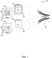
- FIG. 1 is a diagram illustrating an optical interface for a dual channel, optical fiber transceiver 10.
- Transceiver 10 includes a passive optical Y-coupler 12 for separating and combining optical signals.
- transceiver 10 is a chip-on-chip transceiver that incorporates a LED (Light Emitting Diode or Laser Diode) and a PD (Photo Detector).
- Transceiver 10 is compact and low cost.
- transceiver A 14 transmits and receives optical signals at a first wavelength while transceiver B 16 transmits and receives optical signals at a second wavelength.
- the passive optical Y-coupler 12 acts as a combiner for transceivers A 14 and B 16 in the transmit direction and acts as a splitter in the receive direction. Since the optical fiber associated with Y-coupler 12 carries both wavelengths, low cost dielectric filter films 18 and 20 have central cut outs, 22 and 24 respectively, therein to allow for the LED to transmit unimpeded through the respective cut out while filtering out the second wavelength, and preventing it from reaching the respective photo detector (and allowing the first wavelength to reach the photo detector.)
- the transceiver 14 includes a transmitter (LED) 30 and a receiver (photo detector) 32 operating at a first wavelength.
- the filter 18 allows the transmission from transmitter 30, at the first wavelength, through the cut out 22, and also allows the reception of signals at the first wavelength at receiver 32, through the filtering portion 40 of filter 18.
- the filtering portion 40 of filter 18 prevents optical signals at the second wavelength from reaching the receiver 32.
- the transceiver 16 includes a transmitter (LED) 50 and a receiver (photo detector (PD)) 52 operating at a second wavelength.
- the filter 20 allows the transmission from transmitter 50, at the second wavelength, through the cut out 24, and also allows the reception of signals at the second wavelength at receiver 52, through the filtering portion 60 of filter 20.
- the filtering portion 60 of filter 20 prevents optical signals at the first wavelength from reaching the receiver 52.
- transmission and reception may be simultaneous, as long as the wavelengths are different.
- an optical signal at a first wavelength may be received at receiver 30 while a signal at a second wavelength it emanating from transmitter 52.
- the shape of the Y-coupler 12, filters 18 and 20, and the transceivers 14 and 16 is somewhat arbitrary.
- the square shape associated with filters 18 and 20, and transceivers 14 and 16, is but one example.
- Other embodiments, such as round, rectangular, triangular, and other shapes may be implemented.
- the same constraints apply to the Y-coupler 12, which may have a cross-section that is other than round.
- the chip-on-chip transceiver incorporating both dual transmitters (LEDs) and dual receivers (PDs) enables compact size and low cost for a dual transceiver. For example, if first and second wavelengths are used, the first transceiver transmits and receives at the first wavelength, while the second transceiver transmits and receives at the second wavelength.
- the passive optical Y-coupler 12 acts as a combiner for the two transceivers in the transmit direction and acts as a splitter in the receive direction.
- the low cost dielectric filter film has a cut out in the middle to allow for the LED associated with the first wavelength to transmit unimpeded therethrough while the outer perimeter of the filter film filters out the second wavelength from reaching the photo detector, and also allowing the first wavelength to pass through to reach the photo detector.
- Other configurations for the filter may be implemented, based on the configuration of the transmitting LED with respect to the receiving photo-detector.
- Y-coupler may be fabricated used plastic or glass, based on the wavelengths of the light used. As is well known, plastic is often used in the visible light range while glass is often used in the infrared light range.
- the Y-coupler maybe implemented using a variety of methods including tapered optical fiber, silicon waveguide or polymer waveguide.
- FIG 2 is a functional diagram of an avionic computer 100 that incorporates two of the dual channel, optical fiber transceivers described above.
- Transceivers 102 and 104 each provide an optical fiber communication interface.
- Avionic computers of the type similar to avionic computer 100 are sometimes referred to as line replaceable units (LRUs) and transceivers 102 and 104 are functionally equivalent to transceiver 10 (shown in Figure 1 ).
- LRUs line replaceable units
- avionics computer 100 includes one or more host processors 110 and 112. These host processors 110 and 112 communicate with a pair of communications controllers 120 and 122 which provide respective interfaces to transceivers 102 and 104. It should be noted that there are multiple possible configurations for avionics computer 100, and the configuration illustrated in Figure 2 is but one example. Generally, all the configurations will utilize some type of processor for the handling of application data 130, configuration data 132, and health maintenance data 134, all of which are stored in computer memory and accessible by the one or more processors.
- application data 130 is routed bidirectionally to and from the processors 110 and 112 through the communications controllers 120 and 122.
- the communications controllers 120 and 122 are communicatively coupled to both transceivers 102 and 104, which are respectively coupled to individual single fiber busses 140 and 142.
- the application data 130 is transmitted and received on the busses 140 and 142 at a first wavelength.
- Configuration data 132 is received on the busses 140 and 142 at a second wavelength, filtered by the filters and routed to the memory through the transceivers 102 and 104, communications controllers 120 and 122, and processors 110 and 112.
- Health maintenance data 134 is retrieved from the memory by processors 110 and 112, forwarded through the communications controllers 120 and 122 to the transceivers 102 and 104 and transmitted on the busses 140 and 142 at the second wavelength.
- the transceivers 102 and 104 are configured as described above with respect to transceiver 10 in that they include a first transmitter and receiver pair (150 and 160 respectively) operating at a first wavelength (based on the filters 170 and 172) and a second transmitter and receiver pair (152 and 162 respectively) operating at a second wavelength (based on the filters 174 and 176).
- the filters associated with each transmitter/receiver pair are utilized as described above.
- Filters 170 and 172 allow the transmissions therethrough from transceivers 150 and 160, at the first wavelength (application data to be transmitted on busses 140 and 142), through a cut out (not shown in Figure 2 ), and also allows the reception of signals at the first wavelength (application data received via busses 140 and 142) at transceivers 150 and 160, through the filtering portion of the respective filter 170 and 172.
- the filtering portion of filters 170 and 172 prevent optical signals at the second wavelength (configuration data and health maintenance data) from reaching the transceiver 152 and 162.
- filters 174 and 176 allow the transmission from transceivers 152 and 162, at the second wavelength (health maintenance data to be transmitted on busses 140 and 142), through a cut out (not shown in Figure 2 ), and also allows the reception of signals at the second wavelength (configuration data received via busses 140 and 142) at transceivers 152 and 162, through the filtering portion of the respective filter 174 and 176.
- the filtering portion of filters 174 and 176 prevent optical signals at the first wavelength (configuration data) from reaching the transceivers 150 and 160.
- Each avionic computer or LRU in a system architecture typically incorporates dual redundant data links for fault tolerance and resource availability. Whether the LRU deploys a single microprocessor or dual microprocessor architecture depends on the requirement for that avionic system.
- each processor 110 and 112 is communicatively coupled to two communication controllers 120 and 122.
- the controllers can be of the same type, or they may be different, incorporating one or more communication protocols for flexibility.
- Each controller 120 and 122 is communicatively coupled to two optical transceivers 102 and 104 in a crossed strap configuration to allow the optical fibers to carry dual, but distinguishable optical communication protocols. Through the utilization of bidirectional, half duplex transceivers, only two wavelengths are needed to handle all sensing/control data (application data) and all configuration and health maintenance data.
- FIG. 3 is a diagram illustrating a system architecture 200 that incorporates avionics computer 100 and multiple other avionics LRUs 202, 204, and 206, each of which provides one or more specific avionic functions.
- Avionics computer 100 and avionics LRUs 202, 204, and 206 are collectively referred to as avionics units.
- System architecture 200 further includes a central health maintenance database 210 and a configuration database 212.
- Avionics computer 100, avionic LRUs 202, 204, 206, central health maintenance database 210 and configuration database 212 are communicatively interconnected utilizing a multi-port network hub controller 220.
- Communication channels are redundant in that each of the components of system architecture 200 are connected to busses 140 and 142 (also shown in Figure 2 ) and at least the avionics computers (LRUs) (100, 202, 204, and 206) incorporate the transceiver/filter configurations described herein. As all of the components of system architecture 200 incorporate the above described embodiments, full avionic data service over a single optical fiber results.
- busses 140 and 142 also shown in Figure 2
- LRUs avionics computers
- Each avionics LRU incorporates and utilizes dual redundant optical fibers for fault tolerance, and each optical fiber carries dual first and second wavelengths to provide the full avionic data transmission services that have been described herein.
- Dual redundant network hubs such as multi-port network hub controller 220, are implemented within system architecture 200 for fault tolerance with each avionic computer/LRU connected to each of the multiple controllers.
- Each network hub controller 220 is utilized to connect the optical interfaces of multiple avionic computer/LRUs together, as well as to provide an interface to the central health maintenance database 210 and configuration database 212.
- These network hub controllers 220 can be cascaded to connect as many avionic computer/LRUs as allowed by the implemented communication protocols.
- Either active hubs (with active optoelectronics) or passive hubs (no electronics) can be utilized, depending on the quantity of LRU nodes on the data bus. Obviously a passive hub can only divide optical power to a limited number of nodes. Also, both active and passive hubs can be utilized in a mixed topology.
- the channel having a wavelength associated with the configuration data/health maintenance data can be utilized to supplement the sensing/control (application) data channel.
- both channels can be used to increase the data bandwidth.
- the units receiving and supplying such data would have to be operable at both wavelengths so that the filtering mechanisms described herein would not impede communications.
- both channels would have to utilize the same communication protocol.
- a file transfer channel can utilize a different communication protocol from the control data channel.
- full duplex operation of sensing/control (application) data can be achieved by replacing the half duplex transceiver with a full duplex transceiver.
- Such a transceiver has a separate LED and photodetector within the same package (not chip on chip), and utilizes different wavelengths for transmission and reception of application data.
- a full duplex transceiver typically utilizes a wave division multiplexer (WDM) mirror within the transceiver to separate the two wavelengths.
- WDM wave division multiplexer
- the embodiments when incorporated into an aircraft configuration, present a significant weight savings over the currently utilized twisted-pair wire.
- the embodiments provide significant savings in part weight, volume, cost, fabrication, assembly, handling, inventory, installation, inspection, and maintenance.
- the embodiments invention improve bandwidth and data flow efficiency while reducing data latency and jitter.
- utilization of optical fiber instead of conventional wiring reduces airplane systems susceptibility to EMF and lightning strike.
- full avionic data services of control data, sensor data, software configuration data, and health maintenance data can be transmitted across a single optical fiber without the configuration data and health data interfering with the control and sensor data thereby minimizing critical data latency and jitter.
- the embodiments described herein result in a system capable of supporting a method for adding concurrent file transfer capabilities (such as configuration data loading to a host computer and health management traffic from a host computer) to an existing sensing and control data architecture without interfering with the transmission and reception of sensing/control data, and without adding any wiring to an aircraft.
- the above described architecture utilizes only two optical wavelengths, while still supporting a full avionic data service, and utilizing a single optical fiber (a second optical is provided for redundancy.
- the described embodiments support bidirectional, half duplex transmission and reception of control/sensing (application) data and bidirectional, half duplex configuration data loading and health management data transmissions.
- the embodiments support simultaneous operation of same or different communication protocols, one for sensing/control (application) data and one for configuration and health maintenance data.
Landscapes
- Physics & Mathematics (AREA)
- Electromagnetism (AREA)
- Engineering & Computer Science (AREA)
- Computer Networks & Wireless Communication (AREA)
- Signal Processing (AREA)
- Optical Communication System (AREA)
Abstract
Description
- The field of the invention relates generally to fiber optic networks, and more specifically, to methods and systems for providing full avionics data services over a single fiber using two wavelengths. Full data services, at least it relates to an avionic computer, generally means transmission and/or reception of mission data (control and/or sensing), health maintenance status, and configuration data loading.
- The electrical data links utilized in most aircraft incorporate a first twisted pair of conductors to transmit signals, and a second twisted pair of conductors to receive sensing and/or control data. In addition, interfaces for file transfer functions such as configuration data loading and health maintenance data are also required and utilized. While about 10% of aircraft data links are high speed backbones that often require full duplex operation such as a switched network, the other 90% are lower speed access networks that typically use half duplex operation on a multicast or bus network. Typically, aircraft sensing and/or control data is periodically transmitted (or received) and these messages are generally a fixed size. File transfer data messages are not periodic. Instead, file transfer data messages are transmitted on demand and are generally of irregular file size. Data loading messages are necessary to change the configuration of airborne computing equipment to adapt to different computing applications and flight missions.
- Health maintenance messages are one type of file transfer data messages that are incorporated and utilized to report health status of aircraft equipment for fast maintenance action and avoidance of long turn around time at an airport. Due to increasing functionality and capability of avionic equipment, health maintenance and configuration data have increased exponentially for each new aircraft configuration. Navigation databases and intelligent engine messaging are relevant examples of applications with large amounts of configuration and health maintenance data.
- Such data can take several hours to transfer, however, turn around times at airport terminals are generally limited to about fifteen minutes. It is relatively easy to contemplate that it is costly for an aircraft to be grounded for maintenance. Typically, health maintenance data is time shared with control data on the same data link. Therefore, bandwidth would be reduced and the latency and jitter of the critical control data would be increased to accommodate the additional health maintenance data traffic.
- Ideally, multiple pairs of copper wiring are used to send and receive sensing data, control data, configuration data, and health maintenance data. In a typical scenario, a file to be transferred, such as a health maintenance data file, is disassembled into dozens or hundreds of smaller pieces, so the transmission of this data can be time multiplexed with control data in the same stream. These pieces must be reassembled into the health maintenance data file at the receiving end. When time multiplexed, configuration and health maintenance data is time shared with control data on the same data link. Transmission of health maintenance data, for example, reduces the bandwidth available for the control data in order to accommodate additional health maintenance data traffic. One possible result is additional latency and jitter of the critical control data, since the computer has to perform tasks to separate the different data types and disassemble (or reassemble) data files as mentioned above.
- File transfer data messages such as health maintenance messages must either be time shared with control data on a single data link or enabled utilizing a separate data link. Although the loading of new configuration data for an article of aircraft equipment can be delayed and performed at a convenient time, such as when the subject computer is not in mission operation mode, the health maintenance data needs to be transmitted concurrently to provide for the desired goal of fast maintenance actions. It is desirable to perform configuration data loading processes in real time, for example, to reconfigure one or more avionics computers "on the fly" to adapt to different phases of a single flight.
- Entities involved with health maintenance data have been requesting dedicated health maintenance data links, utilizing separate wiring, for some time to help reduce airline operation cost. For this desired simultaneous and non interfering operation, additional electrical cabling and connectors must be added to each aircraft computer (which are sometimes referred to as line replaceable units (LRUs)). Unfortunately, such a solution increases LRU and aircraft costs, increases aircraft weight, and affects volume, installation and maintenance considerations.
- SummaryIn one aspect, a method for transmission of multiple, independent data packages across a single optical fiber utilizing both time division multiplexing and wavelength division multiplexing is provided. The method includes transmitting a first data package across the single optical fiber at a first wavelength, and transmitting a second data package across the same optical fiber at a second wavelength, in either the same direction or in a direction opposite as the first data package, wherein the second data package transmission may be concurrent with the first data package transmission. The method also includes separating the data package transmissions into two optical paths, filtering the second wavelength from a first of the two optical paths, detecting the first data package at the first wavelength, filtering the first wavelength from a second of the two optical paths; and detecting the second data package data at the second wavelength.
- In another aspect, an optical transceiver is provided that includes a first optical transmitter and receiver pair configured for operation at a first wavelength, a second optical transmitter and receiver pair configured for operation at a second wavelength, and an optical coupler configured to couple optical signals from the first optical transmitter and receiver pair and the second optical transmitter and receiver pair, and route the coupled optical signals from the optical coupler to a single optical fiber.
- In still another aspect, an avionics unit is provided. The avionics unit includes a processing device, a computer memory associated with the processing device, an optical transceiver, and at least one communication controller configured to provide a communications interface between the processing device and the optical transceiver. The memory is configured to store at least application data, health maintenance data, and configuration data associated with the avionics unit. The optical transceiver includes a first optical transmitter and receiver pair configured for operation at a first wavelength and a second optical transmitter and receiver pair configured for operation at a second wavelength. The application data is transmitted from and received by the processing device via the first optical transmitter and receiver pair. The configuration data is received by the processing device via the second optical transmitter and receiver pair. The health maintenance data is transmitted from the processing device via the second optical transmitter and receiver pair.
- In yet another aspect, a network for providing full avionics data services over a single optical fiber is provided. The network includes a first avionics unit comprising an optical interface, a second avionics unit comprising an optical interface, and a single optical fiber configured to provide at least a portion of a communications path between the first avionics unit and the second avionics unit. Each optical interface includes an optical transceiver comprising a first optical transmitter and receiver pair configured for operation at a first wavelength and a second optical transmitter and receiver pair configured for operation at a second wavelength.
- In another aspect, a communications system is provided that includes a plurality of hubs and a plurality of modules. Each hub includes a plurality of optical interfaces, and each module includes at least one optical interface. Each module is optically coupled to at least two of the hubs. Each of the optical interfaces includes an optical transceiver having a first optical transmitter and receiver pair configured for operation at a first wavelength and a second optical transmitter and receiver pair configured for operation at a second wavelength.
- The features, functions, and advantages that have been discussed can be achieved independently in various embodiments of the present invention or may be combined in yet other embodiments further details of which can be seen with reference to the following description and drawings.
-
-
Figure 1 is a diagram illustrating an optical interface for a dual channel, optical fiber transceiver. -
Figure 2 is a functional diagram of an avionic computer that incorporates two of dual channel, optical fiber transceivers shown inFigure 1 . -
Figure 3 is a diagram illustrating a system architecture that incorporates the avionics computer ofFigure 2 . - The described embodiments address the problems described above through utilization of a single optical fiber network that operates with only two wavelengths of light. The embodiments allow a full avionics data service on a single optic fiber network through the implementation of substantially simultaneous transmission of sensing and control data (bidirectional across the fiber) and file transfer data (including configuration data loading in one direction across the fiber and health maintenance data in the other direction across the fiber).
-
Figure 1 is a diagram illustrating an optical interface for a dual channel,optical fiber transceiver 10. Transceiver 10 includes a passive optical Y-coupler 12 for separating and combining optical signals. In one embodiment,transceiver 10 is a chip-on-chip transceiver that incorporates a LED (Light Emitting Diode or Laser Diode) and a PD (Photo Detector). Transceiver 10 is compact and low cost. When two wavelengths are utilized, as depicted inFigure 1 , transceiverA 14 transmits and receives optical signals at a first wavelength whiletransceiver B 16 transmits and receives optical signals at a second wavelength. - The passive optical Y-
coupler 12 acts as a combiner fortransceivers A 14 andB 16 in the transmit direction and acts as a splitter in the receive direction. Since the optical fiber associated with Y-coupler 12 carries both wavelengths, low costdielectric filter films - More specifically, the
transceiver 14 includes a transmitter (LED) 30 and a receiver (photo detector) 32 operating at a first wavelength. Thefilter 18 allows the transmission fromtransmitter 30, at the first wavelength, through the cut out 22, and also allows the reception of signals at the first wavelength atreceiver 32, through the filteringportion 40 offilter 18. The filteringportion 40 offilter 18 prevents optical signals at the second wavelength from reaching thereceiver 32. - In regard to the second wavelength, the
transceiver 16 includes a transmitter (LED) 50 and a receiver (photo detector (PD)) 52 operating at a second wavelength. Thefilter 20 allows the transmission from transmitter 50, at the second wavelength, through the cut out 24, and also allows the reception of signals at the second wavelength atreceiver 52, through the filteringportion 60 offilter 20. The filteringportion 60 offilter 20 prevents optical signals at the first wavelength from reaching thereceiver 52. - It should be noted that transmission and reception may be simultaneous, as long as the wavelengths are different. For example, an optical signal at a first wavelength may be received at
receiver 30 while a signal at a second wavelength it emanating fromtransmitter 52. It should also be noted that the shape of the Y-coupler 12, filters 18 and 20, and thetransceivers filters transceivers coupler 12, which may have a cross-section that is other than round. - The chip-on-chip transceiver incorporating both dual transmitters (LEDs) and dual receivers (PDs) enables compact size and low cost for a dual transceiver. For example, if first and second wavelengths are used, the first transceiver transmits and receives at the first wavelength, while the second transceiver transmits and receives at the second wavelength. The passive optical Y-
coupler 12 acts as a combiner for the two transceivers in the transmit direction and acts as a splitter in the receive direction. Since the optical fiber carries both wavelengths, the low cost dielectric filter film has a cut out in the middle to allow for the LED associated with the first wavelength to transmit unimpeded therethrough while the outer perimeter of the filter film filters out the second wavelength from reaching the photo detector, and also allowing the first wavelength to pass through to reach the photo detector. Other configurations for the filter may be implemented, based on the configuration of the transmitting LED with respect to the receiving photo-detector. - Y-coupler may be fabricated used plastic or glass, based on the wavelengths of the light used. As is well known, plastic is often used in the visible light range while glass is often used in the infrared light range. The Y-coupler maybe implemented using a variety of methods including tapered optical fiber, silicon waveguide or polymer waveguide.
-
Figure 2 is a functional diagram of anavionic computer 100 that incorporates two of the dual channel, optical fiber transceivers described above.Transceivers avionic computer 100 are sometimes referred to as line replaceable units (LRUs) andtransceivers Figure 1 ). - Generally,
avionics computer 100 includes one ormore host processors host processors communications controllers transceivers avionics computer 100, and the configuration illustrated inFigure 2 is but one example. Generally, all the configurations will utilize some type of processor for the handling ofapplication data 130,configuration data 132, andhealth maintenance data 134, all of which are stored in computer memory and accessible by the one or more processors. - Returning to the example of
Figure 2 ,application data 130 is routed bidirectionally to and from theprocessors communications controllers application data 130, and to provide redundancy for fault tolerant operation, thecommunications controllers transceivers application data 130 is transmitted and received on thebusses Configuration data 132 is received on thebusses transceivers communications controllers processors Health maintenance data 134 is retrieved from the memory byprocessors communications controllers transceivers busses - The
transceivers transceiver 10 in that they include a first transmitter and receiver pair (150 and 160 respectively) operating at a first wavelength (based on thefilters 170 and 172) and a second transmitter and receiver pair (152 and 162 respectively) operating at a second wavelength (based on thefilters 174 and 176). The filters associated with each transmitter/receiver pair are utilized as described above. -
Filters transceivers busses 140 and 142), through a cut out (not shown inFigure 2 ), and also allows the reception of signals at the first wavelength (application data received viabusses 140 and 142) attransceivers respective filter filters transceiver - In addition, filters 174 and 176 allow the transmission from
transceivers busses 140 and 142), through a cut out (not shown inFigure 2 ), and also allows the reception of signals at the second wavelength (configuration data received viabusses 140 and 142) attransceivers respective filter filters transceivers - Each avionic computer or LRU in a system architecture typically incorporates dual redundant data links for fault tolerance and resource availability. Whether the LRU deploys a single microprocessor or dual microprocessor architecture depends on the requirement for that avionic system. As shown in the
avionics computer 100 ofFigure 2 , eachprocessor communication controllers controller optical transceivers -
Figure 3 is a diagram illustrating asystem architecture 200 that incorporatesavionics computer 100 and multipleother avionics LRUs Avionics computer 100 andavionics LRUs System architecture 200 further includes a centralhealth maintenance database 210 and aconfiguration database 212.Avionics computer 100,avionic LRUs health maintenance database 210 andconfiguration database 212 are communicatively interconnected utilizing a multi-portnetwork hub controller 220. Communication channels are redundant in that each of the components ofsystem architecture 200 are connected tobusses 140 and 142 (also shown inFigure 2 ) and at least the avionics computers (LRUs) (100, 202, 204, and 206) incorporate the transceiver/filter configurations described herein. As all of the components ofsystem architecture 200 incorporate the above described embodiments, full avionic data service over a single optical fiber results. - Each avionics LRU incorporates and utilizes dual redundant optical fibers for fault tolerance, and each optical fiber carries dual first and second wavelengths to provide the full avionic data transmission services that have been described herein. Dual redundant network hubs, such as multi-port
network hub controller 220, are implemented withinsystem architecture 200 for fault tolerance with each avionic computer/LRU connected to each of the multiple controllers. Eachnetwork hub controller 220 is utilized to connect the optical interfaces of multiple avionic computer/LRUs together, as well as to provide an interface to the centralhealth maintenance database 210 andconfiguration database 212. Thesenetwork hub controllers 220 can be cascaded to connect as many avionic computer/LRUs as allowed by the implemented communication protocols. Either active hubs (with active optoelectronics) or passive hubs (no electronics) can be utilized, depending on the quantity of LRU nodes on the data bus. Obviously a passive hub can only divide optical power to a limited number of nodes. Also, both active and passive hubs can be utilized in a mixed topology. - In a practical example, if the bandwidth needs for the configuration data/health maintenance data are small, the channel having a wavelength associated with the configuration data/health maintenance data can be utilized to supplement the sensing/control (application) data channel. Conversely, during configuration data and/or health maintenance data peak traffic both channels can be used to increase the data bandwidth. In these scenarios, the units receiving and supplying such data would have to be operable at both wavelengths so that the filtering mechanisms described herein would not impede communications.
- In one embodiment, for dual channel use, both channels would have to utilize the same communication protocol. However, a file transfer channel can utilize a different communication protocol from the control data channel. Optionally, full duplex operation of sensing/control (application) data can be achieved by replacing the half duplex transceiver with a full duplex transceiver. Such a transceiver has a separate LED and photodetector within the same package (not chip on chip), and utilizes different wavelengths for transmission and reception of application data. A full duplex transceiver typically utilizes a wave division multiplexer (WDM) mirror within the transceiver to separate the two wavelengths. A WDM mirror allows pass through of the transmit wavelength from the LED while reflects the receive wavelength to the photodetector.
- The above described embodiments, when incorporated into an aircraft configuration, present a significant weight savings over the currently utilized twisted-pair wire. In addition, by avoiding additional data link twisted-pair wiring for configuration and health maintenance data, the embodiments provide significant savings in part weight, volume, cost, fabrication, assembly, handling, inventory, installation, inspection, and maintenance. Through the described method of wavelength multiplexing of different data, the embodiments invention improve bandwidth and data flow efficiency while reducing data latency and jitter. In addition, utilization of optical fiber instead of conventional wiring reduces airplane systems susceptibility to EMF and lightning strike.
- By utilizing time division multiplexing of data packages as well as wavelength division multiplexing as described herein, full avionic data services of control data, sensor data, software configuration data, and health maintenance data can be transmitted across a single optical fiber without the configuration data and health data interfering with the control and sensor data thereby minimizing critical data latency and jitter.
- Airlines benefit in addition to the weight savings, as the benefits of optical fiber are apparent for ease of maintenance and elimination of data network degradation due to corrosion of wire bonds as well as grounding and shielding. Also, utilization of large core plastic and multimode glass optical fibers allows visible light transmission of different colors for simple visual inspection of active communication.
- The embodiments described herein result in a system capable of supporting a method for adding concurrent file transfer capabilities (such as configuration data loading to a host computer and health management traffic from a host computer) to an existing sensing and control data architecture without interfering with the transmission and reception of sensing/control data, and without adding any wiring to an aircraft. The above described architecture utilizes only two optical wavelengths, while still supporting a full avionic data service, and utilizing a single optical fiber (a second optical is provided for redundancy. The described embodiments support bidirectional, half duplex transmission and reception of control/sensing (application) data and bidirectional, half duplex configuration data loading and health management data transmissions. The embodiments support simultaneous operation of same or different communication protocols, one for sensing/control (application) data and one for configuration and health maintenance data.
- This written description uses examples to disclose the invention, including the best mode, and also to enable any person skilled in the art to practice the invention, including making and using any devices or systems and performing any incorporated methods. The patentable scope of the invention is defined by the claims, and may include other examples that occur to those skilled in the art. Such other examples are intended to be within the scope of the claims if they have structural elements that do not differ from the literal language of the claims, or if they include equivalent structural elements with insubstantial differences from the literal languages of the claims.
- Further embodiments of the invention are illustrated in the following numbered clauses:
- Clause 1. A method for transmission of multiple, independent data packages across a single optical fiber utilizing both time division multiplexing and wavelength division multiplexing, said method comprising: transmitting a first data package across the single optical fiber at a first wavelength; transmitting a second data package across the same optical fiber at a second wavelength, in either the same direction or in a direction opposite as the first data package, wherein the second data package transmission may be concurrent with the first data package transmission; separating the data package transmissions into two optical paths; filtering the second wavelength from a first of the two optical paths; detecting the first data package at the first wavelength; filtering the first wavelength from a second of the two optical paths; and detecting the second data package data at the second wavelength.
- Clause 2. A method according to Clause 1 wherein: transmitting a first data package comprises transmitting one or more of sensor data in a first direction and control data in an opposite direction; and transmitting a first data package comprises transmitting one or more of software configuration data (132) in a first direction and health maintenance data (134) in an opposite direction.
- Clause 3. The method of Clause 1, wherein separating the data transmissions into two optical paths comprises interfacing an optical coupler (12) to the single fiber (140, 142) configured to provide two optical outputs.
- Clause 4. The method of Clause 1 wherein: filtering the second wavelength from a first of the two optical paths comprises filtering the second wavelength from a photo detector (32,52) input associated with the first of the two optical paths; and filtering the first wavelength from a second of the two optical paths comprises filtering the first wavelength from a photo detector input associated with the second of the two optical paths.
- Clause 5. An optical transceiver (10) comprising: a first optical transmitter (30) and receiver pair (32) configured for operation at a first wavelength; a second optical transmitter (50) and receiver pair (52) configured for operation at a second wavelength; and an optical coupler (12) configured to couple optical signals from said first optical transmitter and receiver pair and said second optical transmitter and receiver pair and route the coupled optical signals from said optical coupler to a single optical fiber.
- Clause 6. The optical transceiver (10) of Clause 5 wherein said first optical transmitter (30) and receiver pair (32) comprises a filter (20), said filter configured to pass optical signals from a transmitter portion of said first optical transmitter and receiver pair, pass optical signals at the first wavelength to a receiver portion of said first optical transmitter and receiver pair, and prevent optical signals at the second wavelength from impinging the receiver portion of said first optical transmitter and receiver pair.
- Clause 7. The optical transceiver (10) of Clause 5 wherein said second optical transmitter (30) and receiver pair (32) comprises a filter (20), said filter configured to pass optical signals from a transmitter portion of said second optical transmitter and receiver pair, pass optical signals at the second wavelength to a receiver portion of said second optical transmitter and receiver pair, and prevent optical signals at the first wavelength from impinging the receiver portion of said second optical transmitter and receiver pair.
- Clause 8. The optical transceiver of Clause 5 wherein said optical coupler is configured to: combine optical signals received from said first optical transmitter (30) and receiver pair (32) and said second optical transmitter (50) and receiver pair (52); and separate the signal received from the single optical fiber into two separate optical paths.
- Clause 9. An avionics unit, comprising: a processing device (110,112); a computer memory associated with said processing device, said memory configured to store at least application data (130) associated with said unit, health maintenance data (134) associated with said unit, and configuration data (132) associated with said unit; an optical transceiver (10) comprising a first optical transmitter (30) and receiver pair (32) configured for operation at a first wavelength and a second optical transmitter (50) and receiver pair (52) configured for operation at a second wavelength; and at least one communication controller (120,122) configured to simultaneously provide a communications interface between said processing device and said optical transceiver, application data (130) transmitted from and received by said processing device via said first optical transmitter and receiver pair, configuration data (132) received by said processing device via said second optical transmitter and receiver pair, and health maintenance data (134) transmitted from said processing device via said second optical transmitter and receiver pair.
-
Clause 10. The avionics unit of Clause 9 comprising a plurality of said optical transceivers (12,14,102,104) communicatively coupled to said processing device via said at least one communications controller. - Clause 11. The avionics unit of Clause 9 wherein: said first optical transmitter (30) and receiver pair (32) comprises a first filter (40), said first filter configured to pass optical signals from a transmitter portion of said first optical transmitter and receiver pair, pass optical signals at the first wavelength to a receiver portion of said first optical transmitter and receiver pair, and prevent optical signals at the second wavelength from impinging the receiver portion of said first optical transmitter and receiver pair; and said second optical transmitter (50) and receiver pair (52) comprises a second filter (60), said second filter configured to pass optical signals from a transmitter portion of said second optical transmitter and receiver pair, pass optical signals at the second wavelength to a receiver portion of said second optical transmitter and receiver pair, and prevent optical signals at the first wavelength from impinging the receiver portion of said second optical transmitter and receiver pair.
-
Clause 12. The avionics unit of Clause 9 wherein said optical transceiver (10) comprises an optical coupler (12) configured to: combine optical signals received from said first optical transmitter (30) and receiver pair (32) and said second optical transmitter (50) and receiver pair (52) for output onto a single optical fiber; and separate the signals received from the optical fiber into two separate optical paths. - Clause 13. An aircraft network for providing full avionics data services over a single optical fiber, said network comprising: a first avionics unit comprising an optical interface; a second avionics unit comprising an optical interface; a single optical fiber configured to provide at least a portion of a communications path between said first avionics unit and said second avionics unit, each said optical interface comprising an optical transceiver (10) comprising a first optical transmitter (30) and receiver pair (32) configured for operation at a first wavelength and a second optical transmitter (50) and receiver pair (52) configured for operation at a second wavelength; and a multi-port network hub controller (220) and a plurality of said single optical fibers, said first avionics unit optically connected to said multi-port network hub controller using one of said single optical fibers, and said second avionics unit optically connected to said multi-port network hub controller using one of said single optical fibers.
-
Clause 14. The aircraft network of Clause 13 wherein: said first optical transmitter (30) and receiver pair (32) comprises a first filter (20), said first filter configured to pass optical signals from a transmitter portion of said first optical transmitter and receiver pair, pass optical signals at the first wavelength to a receiver portion of said first optical transmitter and receiver pair, and prevent optical signals at the second wavelength from impinging the receiver portion of said first optical transmitter and receiver pair; and said second optical transmitter (30) and receiver pair (32) comprises a second filter (40), said second filter configured to pass optical signals from a transmitter portion of said second optical transmitter and receiver pair, pass optical signals at the second wavelength to a receiver portion of said second optical transmitter and receiver pair, and prevent optical signals at the first wavelength from impinging the receiver portion of said second optical transmitter and receiver pair. - Clause 15. The aircraft network of Clause 13 wherein each said optical transceiver (10) comprises an optical coupler (12) configured to:
- combine optical signals received from said first optical transmitter (30) and receiver pair (32) and said second optical transmitter (30) and receiver pair (52) for output onto said single optical fiber; and
- separate the signals received from said single optical fiber into two separate optical paths.
-
Clause 16. The aircraft network of Clause 13 wherein said first avionics unit and said second avionics unit each comprise a plurality of said optical interfaces to provide redundant communications paths, each communications path provided over a single optical fiber. - Clause 17. The aircraft network of Clause 13 wherein said first avionics unit and said second avionics unit are configured to transmit and receive application data (130) associated with the respective said avionics unit over said single optical fiber at the first wavelength.
-
Clause 18. The aircraft network of Clause 17 further comprising a configuration data (132) unit configured to provide configuration data to at least one of said first avionic unit and said second avionic unit, said configuration data unit configured to provide the configuration data over said single optical fiber at the second wavelength. - Clause 19. The aircraft network of Clause 17 further comprising a health maintenance data (134) unit configured to receive health maintenance data from at least one of said first avionic unit and said second avionic unit, said health maintenance unit configured to receive the health maintenance data over said single optical fiber at the second wavelength.
-
Clause 20. A communications system, comprising: a plurality of hubs, each said hub comprising a plurality of optical interfaces; and a plurality of modules each comprising at least one optical interface, each said module optically coupled to at least two of said hubs, each said optical interface comprising an optical transceiver (10) comprising a first optical transmitter (30) and receiver pair (32) configured for operation at a first wavelength and a second optical transmitter (50) and receiver pair (52) configured for operation at a second wavelength. - Clause 21. The communications system of
Clause 20 wherein each of said modules is configured to communicate with each of the other said modules via one or more of said hubs.
Claims (13)
- An aircraft network for providing full avionics data services over a single optical fiber, said network comprising:a first avionics unit comprising an optical interface;a second avionics unit comprising an optical interface;a single optical fiber configured to provide at least a portion of a communications path between said first avionics unit and said second avionics unit, each said optical interface comprising an optical transceiver (10) comprising a first optical transmitter (30) and receiver pair (32) configured for operation at a first wavelength and a second optical transmitter (50) and receiver pair (52) configured for operation at a second wavelength; anda multi-port network hub controller (220) and a plurality of said single optical fibers, said first avionics unit optically connected to said multi-port network hub controller using one of said single optical fibers, and said second avionics unit optically connected to said multi-port network hub controller using one of said single optical fibers.
- The aircraft network of Claim 1 wherein:said first optical transmitter (30) and receiver pair (32) comprises a first filter (20), said first filter configured to pass optical signals from a transmitter portion of said first optical transmitter and receiver pair, pass optical signals at the first wavelength to a receiver portion of said first optical transmitter and receiver pair, and prevent optical signals at the second wavelength from impinging the receiver portion of said first optical transmitter and receiver pair; andsaid second optical transmitter (30) and receiver pair (32) comprises a second filter (40), said second filter configured to pass optical signals from a transmitter portion of said second optical transmitter and receiver pair, pass optical signals at the second wavelength to a receiver portion of said second optical transmitter and receiver pair, and prevent optical signals at the first wavelength from impinging the receiver portion of said second optical transmitter and receiver pair.
- The aircraft network of Claim 1 wherein each said optical transceiver (10) comprises an optical coupler (12) configured to:combine optical signals received from said first optical transmitter (30) and receiver pair (32) and said second optical transmitter (30) and receiver pair (52) for output onto said single optical fiber; andseparate the signals received from said single optical fiber into two separate optical paths.
- The aircraft network of Claim 1 wherein said first avionics unit and said second avionics unit each comprise a plurality of said optical interfaces to provide redundant communications paths, each communications path provided over a single optical fiber.
- The aircraft network of Claim 1 wherein said first avionics unit and said second avionics unit are configured to transmit and receive application data (130) associated with the respective said avionics unit over said single optical fiber at the first wavelength.
- The aircraft network of Claim 5 further comprising a configuration data (132) unit configured to provide configuration data to at least one of said first avionic unit and said second avionic unit, said configuration data unit configured to provide the configuration data over said single optical fiber at the second wavelength.
- The aircraft network of Claim 5 further comprising a health maintenance data (134) unit configured to receive health maintenance data from at least one of said first avionic unit and said second avionic unit, said health maintenance unit configured to receive the health maintenance data over said single optical fiber at the second wavelength.
- A communications system, comprising:a plurality of hubs, each said hub comprising a plurality of optical interfaces; anda plurality of modules each comprising at least one optical interface, each said module optically coupled to at least two of said hubs, each said optical interface comprising an optical transceiver (10) comprising a first optical transmitter (30) and receiver pair (32) configured for operation at a first wavelength and a second optical transmitter (50) and receiver pair (52) configured for operation at a second wavelength.
- The communications system of Claim 8 wherein each of said modules is configured to communicate with each of the other said modules via one or more of said hubs.
- An optical transceiver (10) comprising:a first optical transmitter (30) and receiver pair (32) configured for operation at a first wavelength;a second optical transmitter (50) and receiver pair (52) configured for operation at a second wavelength; andan optical coupler (12) configured to couple optical signals from said first optical transmitter and receiver pair and said second optical transmitter and receiver pair and route the coupled optical signals from said optical coupler to a single optical fiber.
- The optical transceiver (10) of Claim 10 wherein said first optical transmitter (30) and receiver pair (32) comprises a filter (20), said filter configured to pass optical signals from a transmitter portion of said first optical transmitter and receiver pair, pass optical signals at the first wavelength to a receiver portion of said first optical transmitter and receiver pair, and prevent optical signals at the second wavelength from impinging the receiver portion of said first optical transmitter and receiver pair.
- The optical transceiver (10) of Claim 10 wherein said second optical transmitter (30) and receiver pair (32) comprises a filter (20), said filter configured to pass optical signals from a transmitter portion of said second optical transmitter and receiver pair, pass optical signals at the second wavelength to a receiver portion of said second optical transmitter and receiver pair, and prevent optical signals at the first wavelength from impinging the receiver portion of said second optical transmitter and receiver pair.
- The optical transceiver of Claim 10 wherein said optical coupler is configured to:combine optical signals received from said first optical transmitter (30) and receiver pair (32) and said second optical transmitter (50) and receiver pair (52); andseparate the signal received from the single optical fiber into two separate optical paths.
Applications Claiming Priority (3)
| Application Number | Priority Date | Filing Date | Title |
|---|---|---|---|
| US12/179,051 US8045858B2 (en) | 2008-07-24 | 2008-07-24 | Methods and systems for providing full avionics data services over a single fiber |
| EP09789963.7A EP2345181B1 (en) | 2008-07-24 | 2009-06-26 | Methods and systems for providing full avionics data services over a single fiber |
| PCT/US2009/048867 WO2010011462A1 (en) | 2008-07-24 | 2009-06-26 | Methods and systems for providing full avionics data services over a single fiber |
Related Parent Applications (2)
| Application Number | Title | Priority Date | Filing Date |
|---|---|---|---|
| EP09789963.7A Division-Into EP2345181B1 (en) | 2008-07-24 | 2009-06-26 | Methods and systems for providing full avionics data services over a single fiber |
| EP09789963.7A Division EP2345181B1 (en) | 2008-07-24 | 2009-06-26 | Methods and systems for providing full avionics data services over a single fiber |
Publications (2)
| Publication Number | Publication Date |
|---|---|
| EP3425822A1 true EP3425822A1 (en) | 2019-01-09 |
| EP3425822B1 EP3425822B1 (en) | 2025-12-24 |
Family
ID=41112675
Family Applications (2)
| Application Number | Title | Priority Date | Filing Date |
|---|---|---|---|
| EP18188057.6A Active EP3425822B1 (en) | 2008-07-24 | 2009-06-26 | Methods and systems for providing full avionics data services over a single fiber |
| EP09789963.7A Active EP2345181B1 (en) | 2008-07-24 | 2009-06-26 | Methods and systems for providing full avionics data services over a single fiber |
Family Applications After (1)
| Application Number | Title | Priority Date | Filing Date |
|---|---|---|---|
| EP09789963.7A Active EP2345181B1 (en) | 2008-07-24 | 2009-06-26 | Methods and systems for providing full avionics data services over a single fiber |
Country Status (6)
| Country | Link |
|---|---|
| US (1) | US8045858B2 (en) |
| EP (2) | EP3425822B1 (en) |
| JP (1) | JP5539349B2 (en) |
| CN (1) | CN102106100B (en) |
| CA (1) | CA2727721C (en) |
| WO (1) | WO2010011462A1 (en) |
Families Citing this family (17)
| Publication number | Priority date | Publication date | Assignee | Title |
|---|---|---|---|---|
| FR2938671B1 (en) * | 2008-11-17 | 2011-06-03 | Sagem Defense Securite | SECURE AVIONIC EQUIPMENT AND ASSOCIATED SECURITY METHOD |
| US9077451B2 (en) | 2009-01-20 | 2015-07-07 | The Boeing Company | Inline optoelectronic converter and associated methods |
| US8750266B2 (en) * | 2009-11-25 | 2014-06-10 | Alcatel Lucent | Dual transmission for communication networks |
| WO2012154958A1 (en) * | 2011-05-10 | 2012-11-15 | Invensys Systems, Inc. | Multi-drop optical communication |
| US8798467B2 (en) * | 2012-06-26 | 2014-08-05 | The Boeing Company | Optical coupler testing system |
| US9300458B2 (en) * | 2013-02-05 | 2016-03-29 | Cable Television Laboratories, Inc. | Transmission opportunity scheduling |
| US10572423B2 (en) * | 2013-05-17 | 2020-02-25 | The Boeing Company | Systems and methods of data communication |
| FR3013468B1 (en) * | 2013-11-15 | 2017-04-28 | European Aeronautic Defence & Space Co Eads France | INPUT / OUTPUT EQUIPMENT FOR ELECTRONIC FURNITURE AND FURNITURE COMPRISING SUCH AN EQUIPMENT |
| WO2015169363A1 (en) * | 2014-05-08 | 2015-11-12 | Telefonaktiebolaget L M Ericsson (Publ) | Method and apparatus for determining propagation delay in a communications network |
| US9628898B2 (en) | 2014-05-13 | 2017-04-18 | Corning Incorporated | Illuminable transmission cable |
| US20150341113A1 (en) * | 2014-05-20 | 2015-11-26 | The Boeing Company | Lighting and data communication system using a remotely located lighting array |
| US9297970B1 (en) * | 2014-11-05 | 2016-03-29 | The Boeing Company | Low cost, connectorless, ruggedized small form factor optical sub-assembly (OSA) and data bus-in-A-box (BIB) |
| EP3289775A2 (en) * | 2015-05-01 | 2018-03-07 | Corning Incorporated | Illuminable transmission cable |
| US10225005B1 (en) * | 2018-03-09 | 2019-03-05 | Elbex Video Ltd. | Communication infrastructure devices and support tools for intelligent residences or businesses and communicating method with and operating intelligent electrical devices |
| US10852494B2 (en) * | 2018-12-11 | 2020-12-01 | The Boeing Company | Avionics pluggable active optical connector |
| US20220223053A1 (en) * | 2019-08-01 | 2022-07-14 | Skytrac Systems Ltd. | Method and system for autonomously tracking distress events on an aircraft in real-time while in flight |
| US12158394B2 (en) | 2021-11-11 | 2024-12-03 | Rohr, Inc. | Detecting fluid leakage at aircraft hatch |
Citations (7)
| Publication number | Priority date | Publication date | Assignee | Title |
|---|---|---|---|---|
| WO2000048339A1 (en) * | 1999-02-10 | 2000-08-17 | Anacom Systems Corporation | Multi-channel wave division multiplexer system |
| EP1063803A1 (en) * | 1999-06-15 | 2000-12-27 | Lucent Technologies Inc. | Wideband optical packet ring network |
| US20030072056A1 (en) * | 2001-10-12 | 2003-04-17 | Takeshi Ota | Wavelength division multiplexer and wavelength division multiplexing system |
| US20050175344A1 (en) * | 2004-02-06 | 2005-08-11 | Utstarcom, Inc. | System and apparatus for a carrier class WDM PON accommodating multiple services or protocols |
| US20060165417A1 (en) * | 2005-01-25 | 2006-07-27 | Finisar Corporation | Optical transceivers with closed-loop digital diagnostics |
| US20060171329A1 (en) * | 2005-01-28 | 2006-08-03 | Jeffrey Ying | Control network with data and power distribution |
| WO2007109277A2 (en) * | 2006-03-21 | 2007-09-27 | The Boeing Company | Single fiber links for full duplex aircraft data network |
Family Cites Families (19)
| Publication number | Priority date | Publication date | Assignee | Title |
|---|---|---|---|---|
| US5108167A (en) | 1990-07-16 | 1992-04-28 | Rockwell International Corporation | Method and apparatus for obtaining a simplified electro-optical signal coupling system |
| US5138675A (en) | 1991-06-12 | 1992-08-11 | Digital Equipment Corporation | Mode scrambler as an optical isolator for higher-coherence lasers in multi-mode fiber plants |
| JPH0998137A (en) * | 1995-10-03 | 1997-04-08 | Mitsubishi Electric Corp | Two-way optical communication method |
| US5963349A (en) | 1997-01-27 | 1999-10-05 | Lucent Technologies Inc. | Inexpensive single-fiber bidirectional data link |
| JP3399832B2 (en) | 1998-04-20 | 2003-04-21 | シャープ株式会社 | Two-way optical communication device and two-way optical communication device |
| US6381045B1 (en) | 1998-06-24 | 2002-04-30 | Lucent Technologies Inc. | Method and apparatus for bidirectional communication over a single optical fiber |
| US6219477B1 (en) * | 1999-06-29 | 2001-04-17 | The Boeing Company | Multiport single path optical system and associated method |
| US6201908B1 (en) | 1999-07-02 | 2001-03-13 | Blaze Network Products, Inc. | Optical wavelength division multiplexer/demultiplexer having preformed passively aligned optics |
| US6476951B1 (en) | 1999-09-14 | 2002-11-05 | Fitel Usa Corp. | Use of mode coupled optical fiber in communications systems |
| US6574020B1 (en) * | 1999-09-23 | 2003-06-03 | Rockwell Collins, Inc. | System and method for optically and mechanically coupling an avionics line replaceable unit with other equipment on an aircraft |
| EP1426799A3 (en) * | 2002-11-29 | 2005-05-18 | Matsushita Electric Industrial Co., Ltd. | Optical demultiplexer, optical multi-/demultiplexer, and optical device |
| US7272323B2 (en) | 2002-12-04 | 2007-09-18 | Omron Network Products, Llc | Bi-directional electrical to optical converter module |
| US6951426B2 (en) | 2003-03-05 | 2005-10-04 | Finisar Corporation | Pad architecture for backwards compatibility for bi-directional transceiver module |
| FR2859330B1 (en) | 2003-08-29 | 2007-01-26 | Thales Sa | MONO-TRACK COMMUNICATION DEVICE FOR OPTICAL FIBER |
| US7392263B2 (en) * | 2005-02-28 | 2008-06-24 | Microsoft Corporation | File system represented inside a database |
| US20060239609A1 (en) * | 2005-04-26 | 2006-10-26 | Sorin Wayne V | Methods and apparatuses to increase wavelength channels in a wavelength-division-multiplexing passive-optical-network |
| KR100711201B1 (en) * | 2005-08-09 | 2007-04-24 | 한국과학기술원 | Long-distance Transmission Wavelength Division Multiplexing Passive Optical Subscriber Network Using Positioning of Broadband Incoherent Light Source |
| WO2007078805A1 (en) | 2005-12-28 | 2007-07-12 | Intel Corporation | Bi-directional parallel optical link |
| JP2007187793A (en) * | 2006-01-12 | 2007-07-26 | Nec Corp | Optical module |
-
2008
- 2008-07-24 US US12/179,051 patent/US8045858B2/en active Active
-
2009
- 2009-06-26 EP EP18188057.6A patent/EP3425822B1/en active Active
- 2009-06-26 EP EP09789963.7A patent/EP2345181B1/en active Active
- 2009-06-26 WO PCT/US2009/048867 patent/WO2010011462A1/en not_active Ceased
- 2009-06-26 CA CA2727721A patent/CA2727721C/en active Active
- 2009-06-26 JP JP2011520070A patent/JP5539349B2/en active Active
- 2009-06-26 CN CN200980129028.2A patent/CN102106100B/en active Active
Patent Citations (7)
| Publication number | Priority date | Publication date | Assignee | Title |
|---|---|---|---|---|
| WO2000048339A1 (en) * | 1999-02-10 | 2000-08-17 | Anacom Systems Corporation | Multi-channel wave division multiplexer system |
| EP1063803A1 (en) * | 1999-06-15 | 2000-12-27 | Lucent Technologies Inc. | Wideband optical packet ring network |
| US20030072056A1 (en) * | 2001-10-12 | 2003-04-17 | Takeshi Ota | Wavelength division multiplexer and wavelength division multiplexing system |
| US20050175344A1 (en) * | 2004-02-06 | 2005-08-11 | Utstarcom, Inc. | System and apparatus for a carrier class WDM PON accommodating multiple services or protocols |
| US20060165417A1 (en) * | 2005-01-25 | 2006-07-27 | Finisar Corporation | Optical transceivers with closed-loop digital diagnostics |
| US20060171329A1 (en) * | 2005-01-28 | 2006-08-03 | Jeffrey Ying | Control network with data and power distribution |
| WO2007109277A2 (en) * | 2006-03-21 | 2007-09-27 | The Boeing Company | Single fiber links for full duplex aircraft data network |
Also Published As
| Publication number | Publication date |
|---|---|
| US8045858B2 (en) | 2011-10-25 |
| EP2345181A1 (en) | 2011-07-20 |
| US20100021174A1 (en) | 2010-01-28 |
| CA2727721A1 (en) | 2010-01-28 |
| EP2345181B1 (en) | 2018-11-28 |
| CA2727721C (en) | 2013-11-26 |
| JP2011529297A (en) | 2011-12-01 |
| CN102106100A (en) | 2011-06-22 |
| JP5539349B2 (en) | 2014-07-02 |
| CN102106100B (en) | 2014-03-19 |
| WO2010011462A1 (en) | 2010-01-28 |
| EP3425822B1 (en) | 2025-12-24 |
Similar Documents
| Publication | Publication Date | Title |
|---|---|---|
| US8045858B2 (en) | Methods and systems for providing full avionics data services over a single fiber | |
| US11166089B2 (en) | System for increasing fiber port density in data center applications | |
| US8301867B1 (en) | Secondary core ONU to OLT via internal EPON bus coupled multi-core processor for integrated modular avionic system | |
| US8032032B2 (en) | Bi-directional optical link between multiple data sources and a processing node in an avionics platform | |
| US9660757B2 (en) | Low latency fiber optic local area network | |
| US20090304387A1 (en) | Optical data network for bilateral communication between a plurality of communication nodes | |
| JP2011529297A5 (en) | ||
| KR20240110892A (en) | Optical modules, ferrules and fiber optic connectors | |
| US11563642B2 (en) | Smart point of presence (SPOP) aircraft-based high availability edge network architecture | |
| US11990939B2 (en) | Optical module | |
| US10382364B2 (en) | Optical access device and optical access system | |
| US11477088B2 (en) | Smart point of presence (SPOP) devices for aircraft-based high availability edge network architecture | |
| AS Jr et al. | Wavelength division multiplexed (WDM) optical technology solutions for next generation aerospace networks | |
| WO2016164769A1 (en) | Data center endpoint network device with built in switch | |
| CN108462550B (en) | A splicing structure of wavelength division multiplexing system | |
| KR102858105B1 (en) | Ethernet based communication module | |
| Kosyanchuk et al. | Analysis of the requirements to information exchange protocol for an all-optical onboard network | |
| Weaver et al. | Photonic Exchange Network: a reconfigurable data network for mobile platforms | |
| Annighoefer et al. | Multi-core Fiber and Power-limited Optical Network Topology Optimization with MILP | |
| Habiby et al. | Optical network architecture, technology and component challenges in aircraft network applications | |
| Chand et al. | An approach to reducing SWAP and cost for avionics high-speed optical data networks | |
| CN121690381A (en) | Multimode PON-based reliable control method for airborne data bus optical link | |
| CN120881426A (en) | Vehicle-mounted communication system and vehicle | |
| Braun | Hybrid WDM ring-bus optical network | |
| Weigand | Fiber optic and broadband coaxial cable data network alternatives for a flying mission base |
Legal Events
| Date | Code | Title | Description |
|---|---|---|---|
| PUAI | Public reference made under article 153(3) epc to a published international application that has entered the european phase |
Free format text: ORIGINAL CODE: 0009012 |
|
| STAA | Information on the status of an ep patent application or granted ep patent |
Free format text: STATUS: REQUEST FOR EXAMINATION WAS MADE |
|
| 17P | Request for examination filed |
Effective date: 20180808 |
|
| AC | Divisional application: reference to earlier application |
Ref document number: 2345181 Country of ref document: EP Kind code of ref document: P |
|
| AK | Designated contracting states |
Kind code of ref document: A1 Designated state(s): AT BE BG CH CY CZ DE DK EE ES FI FR GB GR HR HU IE IS IT LI LT LU LV MC MK MT NL NO PL PT RO SE SI SK TR |
|
| STAA | Information on the status of an ep patent application or granted ep patent |
Free format text: STATUS: EXAMINATION IS IN PROGRESS |
|
| 17Q | First examination report despatched |
Effective date: 20210528 |
|
| RAP3 | Party data changed (applicant data changed or rights of an application transferred) |
Owner name: THE BOEING COMPANY |
|
| GRAP | Despatch of communication of intention to grant a patent |
Free format text: ORIGINAL CODE: EPIDOSNIGR1 |
|
| STAA | Information on the status of an ep patent application or granted ep patent |
Free format text: STATUS: GRANT OF PATENT IS INTENDED |
|
| RIC1 | Information provided on ipc code assigned before grant |
Ipc: H04B 10/40 20130101AFI20250618BHEP |
|
| INTG | Intention to grant announced |
Effective date: 20250721 |
|
| P01 | Opt-out of the competence of the unified patent court (upc) registered |
Free format text: CASE NUMBER: UPC_APP_5549_3425822/2025 Effective date: 20250901 |
|
| GRAS | Grant fee paid |
Free format text: ORIGINAL CODE: EPIDOSNIGR3 |
|
| GRAA | (expected) grant |
Free format text: ORIGINAL CODE: 0009210 |
|
| STAA | Information on the status of an ep patent application or granted ep patent |
Free format text: STATUS: THE PATENT HAS BEEN GRANTED |
|
| AC | Divisional application: reference to earlier application |
Ref document number: 2345181 Country of ref document: EP Kind code of ref document: P |
|
| AK | Designated contracting states |
Kind code of ref document: B1 Designated state(s): AT BE BG CH CY CZ DE DK EE ES FI FR GB GR HR HU IE IS IT LI LT LU LV MC MK MT NL NO PL PT RO SE SI SK TR |
|
| REG | Reference to a national code |
Ref country code: CH Ref legal event code: F10 Free format text: ST27 STATUS EVENT CODE: U-0-0-F10-F00 (AS PROVIDED BY THE NATIONAL OFFICE) Effective date: 20251224 Ref country code: GB Ref legal event code: FG4D |
|
| REG | Reference to a national code |
Ref country code: DE Ref legal event code: R096 Ref document number: 602009065631 Country of ref document: DE |
|
| REG | Reference to a national code |
Ref country code: LT Ref legal event code: MG9D |
|
| PG25 | Lapsed in a contracting state [announced via postgrant information from national office to epo] |
Ref country code: NO Free format text: LAPSE BECAUSE OF FAILURE TO SUBMIT A TRANSLATION OF THE DESCRIPTION OR TO PAY THE FEE WITHIN THE PRESCRIBED TIME-LIMIT Effective date: 20260324 |
|
| PG25 | Lapsed in a contracting state [announced via postgrant information from national office to epo] |
Ref country code: FI Free format text: LAPSE BECAUSE OF FAILURE TO SUBMIT A TRANSLATION OF THE DESCRIPTION OR TO PAY THE FEE WITHIN THE PRESCRIBED TIME-LIMIT Effective date: 20251224 Ref country code: HR Free format text: LAPSE BECAUSE OF FAILURE TO SUBMIT A TRANSLATION OF THE DESCRIPTION OR TO PAY THE FEE WITHIN THE PRESCRIBED TIME-LIMIT Effective date: 20251224 |
|
| PG25 | Lapsed in a contracting state [announced via postgrant information from national office to epo] |
Ref country code: LV Free format text: LAPSE BECAUSE OF FAILURE TO SUBMIT A TRANSLATION OF THE DESCRIPTION OR TO PAY THE FEE WITHIN THE PRESCRIBED TIME-LIMIT Effective date: 20251224 |
|
| REG | Reference to a national code |
Ref country code: NL Ref legal event code: MP Effective date: 20251224 |
|
| PG25 | Lapsed in a contracting state [announced via postgrant information from national office to epo] |
Ref country code: BG Free format text: LAPSE BECAUSE OF FAILURE TO SUBMIT A TRANSLATION OF THE DESCRIPTION OR TO PAY THE FEE WITHIN THE PRESCRIBED TIME-LIMIT Effective date: 20251224 |
|
| REG | Reference to a national code |
Ref country code: AT Ref legal event code: MK05 Ref document number: 1871790 Country of ref document: AT Kind code of ref document: T Effective date: 20251224 |
|
| PG25 | Lapsed in a contracting state [announced via postgrant information from national office to epo] |
Ref country code: NL Free format text: LAPSE BECAUSE OF FAILURE TO SUBMIT A TRANSLATION OF THE DESCRIPTION OR TO PAY THE FEE WITHIN THE PRESCRIBED TIME-LIMIT Effective date: 20251224 |
|
| PG25 | Lapsed in a contracting state [announced via postgrant information from national office to epo] |
Ref country code: LT Free format text: LAPSE BECAUSE OF FAILURE TO SUBMIT A TRANSLATION OF THE DESCRIPTION OR TO PAY THE FEE WITHIN THE PRESCRIBED TIME-LIMIT Effective date: 20251224 |
|
| PG25 | Lapsed in a contracting state [announced via postgrant information from national office to epo] |
Ref country code: ES Free format text: LAPSE BECAUSE OF FAILURE TO SUBMIT A TRANSLATION OF THE DESCRIPTION OR TO PAY THE FEE WITHIN THE PRESCRIBED TIME-LIMIT Effective date: 20251224 |
|
| PG25 | Lapsed in a contracting state [announced via postgrant information from national office to epo] |
Ref country code: PL Free format text: LAPSE BECAUSE OF FAILURE TO SUBMIT A TRANSLATION OF THE DESCRIPTION OR TO PAY THE FEE WITHIN THE PRESCRIBED TIME-LIMIT Effective date: 20251224 |
|
| PGFP | Annual fee paid to national office [announced via postgrant information from national office to epo] |
Ref country code: GB Payment date: 20260629 Year of fee payment: 18 |
|
| PG25 | Lapsed in a contracting state [announced via postgrant information from national office to epo] |
Ref country code: IT Free format text: LAPSE BECAUSE OF FAILURE TO SUBMIT A TRANSLATION OF THE DESCRIPTION OR TO PAY THE FEE WITHIN THE PRESCRIBED TIME-LIMIT Effective date: 20251224 |
|
| PGFP | Annual fee paid to national office [announced via postgrant information from national office to epo] |
Ref country code: DE Payment date: 20260629 Year of fee payment: 18 |
|
| PG25 | Lapsed in a contracting state [announced via postgrant information from national office to epo] |
Ref country code: AT Free format text: LAPSE BECAUSE OF FAILURE TO SUBMIT A TRANSLATION OF THE DESCRIPTION OR TO PAY THE FEE WITHIN THE PRESCRIBED TIME-LIMIT Effective date: 20251224 |
|
| PG25 | Lapsed in a contracting state [announced via postgrant information from national office to epo] |
Ref country code: EE Free format text: LAPSE BECAUSE OF FAILURE TO SUBMIT A TRANSLATION OF THE DESCRIPTION OR TO PAY THE FEE WITHIN THE PRESCRIBED TIME-LIMIT Effective date: 20251224 |
|
| PG25 | Lapsed in a contracting state [announced via postgrant information from national office to epo] |
Ref country code: IS Free format text: LAPSE BECAUSE OF FAILURE TO SUBMIT A TRANSLATION OF THE DESCRIPTION OR TO PAY THE FEE WITHIN THE PRESCRIBED TIME-LIMIT Effective date: 20260424 Ref country code: PT Free format text: LAPSE BECAUSE OF FAILURE TO SUBMIT A TRANSLATION OF THE DESCRIPTION OR TO PAY THE FEE WITHIN THE PRESCRIBED TIME-LIMIT Effective date: 20260424 |
|
| PG25 | Lapsed in a contracting state [announced via postgrant information from national office to epo] |
Ref country code: CZ Free format text: LAPSE BECAUSE OF FAILURE TO SUBMIT A TRANSLATION OF THE DESCRIPTION OR TO PAY THE FEE WITHIN THE PRESCRIBED TIME-LIMIT Effective date: 20251224 |
|
| PGFP | Annual fee paid to national office [announced via postgrant information from national office to epo] |
Ref country code: FR Payment date: 20260625 Year of fee payment: 18 |
|
| PG25 | Lapsed in a contracting state [announced via postgrant information from national office to epo] |
Ref country code: SK Free format text: LAPSE BECAUSE OF FAILURE TO SUBMIT A TRANSLATION OF THE DESCRIPTION OR TO PAY THE FEE WITHIN THE PRESCRIBED TIME-LIMIT Effective date: 20251224 |
|
| PG25 | Lapsed in a contracting state [announced via postgrant information from national office to epo] |
Ref country code: SE Free format text: LAPSE BECAUSE OF FAILURE TO SUBMIT A TRANSLATION OF THE DESCRIPTION OR TO PAY THE FEE WITHIN THE PRESCRIBED TIME-LIMIT Effective date: 20251224 |