EP3425816A1 - Near-field device - Google Patents
Near-field device Download PDFInfo
- Publication number
- EP3425816A1 EP3425816A1 EP18180565.6A EP18180565A EP3425816A1 EP 3425816 A1 EP3425816 A1 EP 3425816A1 EP 18180565 A EP18180565 A EP 18180565A EP 3425816 A1 EP3425816 A1 EP 3425816A1
- Authority
- EP
- European Patent Office
- Prior art keywords
- substance
- field
- attribute
- signal
- characteristic
- Prior art date
- Legal status (The legal status is an assumption and is not a legal conclusion. Google has not performed a legal analysis and makes no representation as to the accuracy of the status listed.)
- Withdrawn
Links
Images



Classifications
-
- H—ELECTRICITY
- H04—ELECTRIC COMMUNICATION TECHNIQUE
- H04B—TRANSMISSION
- H04B5/00—Near-field transmission systems, e.g. inductive or capacitive transmission systems
- H04B5/20—Near-field transmission systems, e.g. inductive or capacitive transmission systems characterised by the transmission technique; characterised by the transmission medium
- H04B5/22—Capacitive coupling
-
- H—ELECTRICITY
- H01—ELECTRIC ELEMENTS
- H01Q—ANTENNAS, i.e. RADIO AERIALS
- H01Q1/00—Details of, or arrangements associated with, antennas
- H01Q1/12—Supports; Mounting means
- H01Q1/22—Supports; Mounting means by structural association with other equipment or articles
- H01Q1/24—Supports; Mounting means by structural association with other equipment or articles with receiving set
-
- H—ELECTRICITY
- H04—ELECTRIC COMMUNICATION TECHNIQUE
- H04B—TRANSMISSION
- H04B5/00—Near-field transmission systems, e.g. inductive or capacitive transmission systems
- H04B5/20—Near-field transmission systems, e.g. inductive or capacitive transmission systems characterised by the transmission technique; characterised by the transmission medium
- H04B5/24—Inductive coupling
- H04B5/26—Inductive coupling using coils
-
- H—ELECTRICITY
- H04—ELECTRIC COMMUNICATION TECHNIQUE
- H04B—TRANSMISSION
- H04B5/00—Near-field transmission systems, e.g. inductive or capacitive transmission systems
- H04B5/70—Near-field transmission systems, e.g. inductive or capacitive transmission systems specially adapted for specific purposes
- H04B5/73—Near-field transmission systems, e.g. inductive or capacitive transmission systems specially adapted for specific purposes for taking measurements, e.g. using sensing coils
-
- G—PHYSICS
- G01—MEASURING; TESTING
- G01N—INVESTIGATING OR ANALYSING MATERIALS BY DETERMINING THEIR CHEMICAL OR PHYSICAL PROPERTIES
- G01N27/00—Investigating or analysing materials by the use of electric, electrochemical, or magnetic means
- G01N27/72—Investigating or analysing materials by the use of electric, electrochemical, or magnetic means by investigating magnetic variables
Definitions
- the present specification relates to systems, methods, apparatuses, devices, articles of manufacture and instructions for near-field signal analysis.
- a near-field device comprising: a near-field receiver coupled to a near-field receiver antenna and a decoder circuit; wherein the near-field receiver antenna is configured to be capacitively coupled at a first location of a first substance; wherein the near-field receiver antenna is configured to receive a first near-field signal from the first substance through the receiver's capacitive coupling; and wherein the decoder circuit is configured to compare an attribute of the first near-field signal to an attribute of a second near-field signal received from a second substance.
- the decoder circuit is configured to indicate the first substance is same as the second substance if the attribute of the first substance is within a predetermined range of the attribute of the second substance.
- the decoder circuit is configured to indicate the first substance is different from the second substance if the attribute of the first substance is outside of a predetermined range of the attribute of the second substance.
- the decoder circuit is configured to assign a quality level to the first substance based on how close the attribute of the first substance is to the attribute of the second substance.
- the first substance includes at least one of: liquid, solid, gas, plasma, saline, glucose, insulin, a structure, an assembly of parts, a mixture, a food, or a set of items.
- the attribute of the received near-field signal is at least one of: a signal strength, a signal to noise ratio, a voltage, an attenuation, a conductivity, or another electrical parameter.
- the attribute of the first near-field signal is affected by at least one of the first substance characteristics: an atomic characteristic, a molecular characteristic, a cellular characteristic, a mixture characteristic, a structural characteristic, a conductive characteristic, a quantity characteristic, or a volume characteristic.
- the capacitive coupling between the receiver antenna and the first substance includes at least one of: an air gap or a container.
- the first substance is more conductive than the container.
- the near-field receiver antenna substantially conforms to a shape of the container.
- the near-field receiver antenna is configured to physically hold the container.
- the first near-field signal includes a carrier frequency that is less than 30 MHz.
- another near-field device including a near-field transmitter coupled to a near-field transmitter antenna and an encoder circuit; wherein the near-field transmitter antenna is configured to be capacitively coupled at a second location on the first substance; wherein the encoder circuit is configured to generate the first near-field signal; and wherein the near-field transmitter antenna is configured to transmit the first near-field signal to the first substance through the transmitter's capacitive coupling.
- the receiver and transmitter antennas are configured to physically hold the first substance.
- the receiver and transmitter antennas are configured to permit the first substance to be removed and replaced with additional substances.
- the first near-field signal is generated by an electric near-field antenna in the transmitter antenna and received by a magnetic near-field antenna in the receiver antenna.
- the first near-field signal is generated by a magnetic near-field antenna in the transmitter antenna and received by an electric near-field antenna in the receiver antenna.
- a method of processing a near-field signal comprising: receiving a first near-field signal from a first substance through a capacitive coupling; comparing an attribute of the first near-field signal to an attribute of a second near-field signal received from a second substance.
- NFEMI Near-field electric and magnetic induction
- Such an antenna can be a coil antenna that allows near field magnetic induction (NFMI).
- Other antennas communicate by means of both magnetic (H) and electric (E) near-fields via near field electric and magnetic induction.
- NFEMI and NFMI devices which, using non-contact capacitive coupling to one or more substances (e.g. fluid, solid, gas), are used identify, differentiate, quality control, or perform other checks on the substance by means of the magnetic and electric near-fields.
- substances e.g. fluid, solid, gas
- transmitter and receiver near-field devices can be positioned at different locations along the substance and attributes of the received near-field signal can be used to either identify the substance or ensure that the substance falls within a quality control range as compared to reference attributes from a known reference substance.
- the near-field device may include: control circuitry, microprocessors, microcontrollers, digital signal processors, data processing units, human interface units, and antennas.
- Such antennas when in close proximity to the substance will generate fields that are substantially confined near the substance, thus providing a strong near-field signal for collecting and analyzing the substance's near-field attributes.
- Such near-field attributes may include: a signal strength, a signal to noise ratio, a voltage, an attenuation, a conductivity, or another electrical parameter.
- the near-field device to be discussed can be used in different possible applications, including: medical, pharmaceutical, industrial, manufacturing, production lines, assembly lines, food processing, mixing, diluting, calibration, and quality control applications.
- Figure 1 is an example first application 100 of a set of near-field devices 102, 110.
- the example first application 100 includes the first near-field device 102 (e.g. for near-field signal transmission and/or reception) positioned at a first location 104 along a substance 106.
- the first near-field device 102 includes a near-field transmitter antenna (not shown), a transmitter circuit (not shown), an encoder circuit (not shown) and is separated from the substance 106 by a dielectric 108 (e.g. air-gap for capacitive coupling).
- a dielectric 108 e.g. air-gap for capacitive coupling
- This example first application 100 also includes a second near-field device 110 (e.g. for near-field signal reception and/or transmission) positioned at a second location 112 along the substance 106.
- the second near-field device 110 includes a near-field receiver antenna (not shown), a receiver circuit (not shown), a decoder circuit (not shown) and a dielectric 114 (e.g. another air-gap for capacitive coupling).
- the substance 106 can be a liquid, solid, gas, plasma, saline, glucose, insulin, a structure, an assembly of parts, a mixture, a food, a set of items, etc. that includes at least one of: an atomic characteristic, a molecular characteristic, a cellular characteristic, a mixture characteristic, a structural characteristic, and a conductive characteristic, a quantity characteristic, or a volume characteristic.
- the first near-field device 102 uses the encoder to generate a transmitted near-field signal 116 having an H-Field 118 (i.e. magnetic near-field) component and an E-Field 120 (i.e. electric near-field) component.
- the first near-field device 102 transmits the near-field signal 116 to the substance 106 through the transmitter's dielectric 108 (i.e. capacitive coupling).
- the second near-field device 110 receives a near-field signal 122 from the substance 106 through the receiver's dielectric 114 (i.e. capacitive coupling).
- This received near-field signal 122 includes attributes that correspond to the transmitted near-field signal 116, but due to the first substance's 106 atomic, molecular, mixture, structural, conductive, quantity and/or volume characteristics, have an H-Field 124 (i.e. magnetic near-field) component and an E-Field 126 (i.e. electric near-field) component, which may or may not differ from the H-Field 118 and E-Field 120 components based on the substance's 106 attributes.
- H-Field 124 i.e. magnetic near-field
- E-Field 126 i.e. electric near-field
- These attributes of the received near-field signal 122 may include at least one of: a signal strength, a signal to noise ratio, a voltage, an attenuation, a conductivity, or another electrical parameter.
- the H-field 118, 124 and E-field 120, 126 arrows in Figure 1 illustrate the magnetic and electric near-field vectors along the substance 106.
- the near-field transmitter antenna is designed so that the magnetic field vector is curved around the substance 106.
- the electric field vector is perpendicular to the substance 106 when the substance 106 is conductive.
- the magnetic field and the electric field are distributed over the length of the substance 106.
- the antenna of the second near-field device 110 is able to convert the H-Field 124 and the E-Field 126 of the received near-field signal 122 into voltages that can be processed by the second near-field device 110.
- the dielectrics 108, 114 for capacitive coupling can be either air-gaps, a container, or some other dielectric medium between the substance 106 and the outside of the near-field devices 102, 110.
- the dielectrics 108, 114 are formed by a substantially non-conductive container, such container can hold a liquid, a gas, a mixture, or perhaps a set of items (e.g. perhaps for measuring a quantity or volume when filling containers with the substance 106).
- the decoder circuit in the second near-field device 110 is configured to compare the attributes of the received near-field signal 122 from the substance 106 to attributes of another received near-field signal (not shown) from a second substance in an apparatus substantially similar to the example first application 100 shown in Figure 1 .
- the second substance in some example embodiments is a known substance that functions as a calibration substance or a standard.
- the decoder circuit is configured to indicate the substance 106 is substantially same as the known second substance if the attributes of the substance 106 are within a predetermined range of the attributes of the second substance.
- the decoder circuit is configured to indicate the substance 106 is different from the second substance if the attributes of the substance 106 are outside of a predetermined range of the attributes of the second substance.
- the decoder circuit is configured to assign a quality level to the substance 106 based on how close the attributes of the substance 106 are to the attributes of the second substance.
- the near-field transmitter antenna can be separated from the near-field receiver antenna over a range of distances (e.g. perhaps 20 cm to 100 cm). The separation however can be increased by using larger transmit voltages to meters.
- the near-field signal includes a carrier frequency that is in some examples ⁇ 30 MHz. However higher frequencies are also possible.
- the example first application 100 of a set of near-field devices 102, 110 can be used in a variety of applications, including: medical, pharmaceutical, industrial, manufacturing, production lines, assembly lines, food processing, mixing, diluting, calibration, and quality control applications.
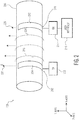
- Figure 2 is an example second application 200 of the set of near-field devices.
- the example second application 200 of a set of near-field devices includes: a near-field transmitter and a near-field receiver.
- the near-field transmitter is positioned at a first location 202 along a container 208.
- the near-field transmitter includes a near-field transmitter antenna 204 and a transmitter and encoder circuit 206.
- the near-field transmitter generates a transmitted near-field signal having an H-Field 218 (i.e. magnetic near-field component) and an E-Field 220 (i.e. electric near-field component).
- the near-field receiver is positioned at a second location 210 along the container 208.
- the near-field receiver includes a near-field receiver antenna 212, a receiver and decoder circuit 214, and a user interface 216.
- the near-field receiver receives a received near-field signal having an H-Field 224 (i.e. magnetic near-field component) and an E-Field 226 (i.e. electric near-field component).
- the container 208 is configured to hold a substance to be measured.
- the container 208 is a non-conductive dielectric so as to enable capacitive coupling between the substance and the antennas 204, 212.
- the container 208 material can include: polymers, glass, or organics.
- the near-field antennas 204, 212 also function as mechanical clamps for holding and securing the container 208.
- a distance between the antenna 204, 212 locations 202, 210 is 10 to 20 cm; however, in other examples the distance can be greater or lesser.
- the transmitter and encoder circuit 206 generates a voltage and a current at a frequency that is converted by the near-field transmitter antenna 204 into the H-Field 218 and E-Field 220 of the transmitted near-field signal.
- the frequency that can be used is defined by dimensions of the antennas 204, 212.
- the wavelength of the transmitted near-field signal should be much larger than sizes of the antennas 204, 212 to ensure that only near-field is generated. For example, if the radio frequency is 10MHz, antenna 204, 212 sizes can be several centimeters.
- the E-Field vector 220 will be orthogonal to the container 208.
- the H-Field vector 218 that is encircling the container 208 can also be used. Both fields 220, 218 follow the container's 208 shape and are attenuated in amplitude along a length of the container 208 by the substance.
- the received near-field signal i.e. the H-Field 224 and the E-Field 2266 are attenuated and are converted by the receiver and decoder circuit 214 to voltages and currents. The amount of measured attenuation is then related to an attribute (e.g. an electrical conductivity) of the substance under test.
- an attribute e.g. an electrical conductivity
- Figure 3 is an example 300 of a first substance 302 and a second substance 304.
- the substances 302, 304 are solids measured using the example first application 100 of Figure 1 .
- the substances 302, 304 are liquids inside containers such as the container 208 of Figure 2 and are measured using the example second application 200, and are placed on, clipped into or otherwise held by the antennas 204, 212.
- just a received near-field signal attribute difference between the substances 302, 304 needs to be known.
- the second substance 304 is known and functions as a reference for identifying, distinguishing or measuring a quality level of the first substance 302.
- Such a known second substance 304 reference can in one example be calibrated and implemented as follows.
- a reference fluid e.g. the second substance 304 having a known electric conductance is inserted into the container 208 of the second application 200 system.
- the near-field transmitter antenna 204 starts generating the near-fields.
- the receiver and decoder circuit 214 measures a received signal strength attribute, and the electric conductance of the reference fluid is calibrated. Additional known substances can also be measured in this way and stored in a memory inside the user interface 216.
- An extended database can thus be built with many reference fluids based on temperature or other environment parameters.
- a fluid under test (e.g. the first substance 302) is inserted in the container 208 of the second application 200 system.
- the near-field transmitter antenna 204 again starts generating the near-fields.
- the receiver and decoder circuit 214 then measure a test signal strength, this is the test fluid signal strength. From the database inside the user interface 216, the fluid under test can be identified.
- Figure 4 are example 400 near-field signals received over various distances from the first substance 302 and the second substance 304.
- location 402 corresponds to either first location 104 or first location 202.
- the rest of the data points in this example 400 correspond to either the second location 112 or the second location 210 at various distances from location 402.
- H and E field-strength are an example attributes being measured for the first and second substances 302, 304, similar data points could be collected in other example embodiments corresponding to other attributes of the first and second substances 302, 304.
- FIG. 5 shows an example received near-field signal, over various distances, from a saline solution substance. Since saline is a liquid, the example second application 200 of Figure 2 could be used to generate this example 500 received signal strength indicator (RSSI) (e.g. voltage) data.
- RSSI received signal strength indicator
- the example 500 RSSI corresponds to a 0.9% Saline solution RSSI received near-field signal at various distances from a transmitted near-field signal.
- the example 500 graph shows attenuation of the RSSI as a function of distance between the near-field transmitter antenna 204 and near-field receiver antenna 212.
- the RSSI is about 87dbuV, which is a relatively strong signal.
- Figure 6 are example 600 received near-field signals, at a same fixed distance, from various saline solutions.
- the container 208 is a plastic pipe about 5 mm in diameter and 1 meter long.
- the RSSI corresponds to received voltages at the near-field receiver for different concentrations of salt water.
- the RSSI depends on the salt concentration which directly influences the measured electric conductivity.
- a near-field device comprising: a near-field receiver coupled to a near-field receiver antenna and a decoder circuit; wherein the near-field receiver antenna is configured to be capacitively coupled at a first location of a first substance; wherein the near-field receiver antenna is configured to receive a first near-field signal from the first substance through the receiver's capacitive coupling; and wherein the decoder circuit is configured to compare an attribute of the first near-field signal to an attribute of a second near-field signal received from a second substance.
- these instructions/steps are implemented as functional and software instructions.
- the instructions can be implemented either using logic gates, application specific chips, firmware, as well as other hardware forms.
- the instructions are embodied as a set of executable instructions in a non-transient computer-readable or computer-usable media which are effected on a computer or machine programmed with and controlled by said executable instructions.
- Said instructions are loaded for execution on a processor (such as one or more CPUs).
- Said processor includes microprocessors, microcontrollers, processor modules or subsystems (including one or more microprocessors or microcontrollers), or other control or computing devices.
- a processor can refer to a single component or to plural components.
- Said computer-readable or computer-usable storage medium or media is (are) considered to be part of an article (or article of manufacture).
- An article or article of manufacture can refer to any manufactured single component or multiple components.
- the non-transient machine or computer-usable media or mediums as defined herein excludes signals, but such media or mediums may be capable of receiving and processing information from signals and/or other transient mediums.
Landscapes
- Engineering & Computer Science (AREA)
- Computer Networks & Wireless Communication (AREA)
- Signal Processing (AREA)
- Arrangements For Transmission Of Measured Signals (AREA)
- Investigating Or Analyzing Materials By The Use Of Electric Means (AREA)
Abstract
One example discloses a near-field device, comprising: a near-field receiver coupled to a near-field receiver antenna and a decoder circuit; wherein the near-field receiver antenna is configured to be capacitively coupled at a first location of a first substance; wherein the near-field receiver antenna is configured to receive a first near-field signal from the first substance through the receiver's capacitive coupling; and wherein the decoder circuit is configured to compare an attribute of the first near-field signal to an attribute of a second near-field signal received from a second substance.
Description
- The present specification relates to systems, methods, apparatuses, devices, articles of manufacture and instructions for near-field signal analysis.
- According to an example embodiment, a near-field device, comprising: a near-field receiver coupled to a near-field receiver antenna and a decoder circuit; wherein the near-field receiver antenna is configured to be capacitively coupled at a first location of a first substance; wherein the near-field receiver antenna is configured to receive a first near-field signal from the first substance through the receiver's capacitive coupling; and wherein the decoder circuit is configured to compare an attribute of the first near-field signal to an attribute of a second near-field signal received from a second substance.
- In another example embodiment, the decoder circuit is configured to indicate the first substance is same as the second substance if the attribute of the first substance is within a predetermined range of the attribute of the second substance.
- In another example embodiment, the decoder circuit is configured to indicate the first substance is different from the second substance if the attribute of the first substance is outside of a predetermined range of the attribute of the second substance.
- In another example embodiment, the decoder circuit is configured to assign a quality level to the first substance based on how close the attribute of the first substance is to the attribute of the second substance.
- In another example embodiment, the first substance includes at least one of: liquid, solid, gas, plasma, saline, glucose, insulin, a structure, an assembly of parts, a mixture, a food, or a set of items.
- In another example embodiment, the attribute of the received near-field signal is at least one of: a signal strength, a signal to noise ratio, a voltage, an attenuation, a conductivity, or another electrical parameter.
- In another example embodiment, the attribute of the first near-field signal is affected by at least one of the first substance characteristics: an atomic characteristic, a molecular characteristic, a cellular characteristic, a mixture characteristic, a structural characteristic, a conductive characteristic, a quantity characteristic, or a volume characteristic.
- In another example embodiment, the capacitive coupling between the receiver antenna and the first substance includes at least one of: an air gap or a container.
- In another example embodiment, further comprising a container configured to hold the first substance.
- In another example embodiment, the first substance is more conductive than the container.
- In another example embodiment, the near-field receiver antenna substantially conforms to a shape of the container.
- In another example embodiment, the near-field receiver antenna is configured to physically hold the container.
- In another example embodiment, the first near-field signal includes a carrier frequency that is less than 30 MHz.
- In another example embodiment, further comprising: another near-field device including a near-field transmitter coupled to a near-field transmitter antenna and an encoder circuit; wherein the near-field transmitter antenna is configured to be capacitively coupled at a second location on the first substance; wherein the encoder circuit is configured to generate the first near-field signal; and wherein the near-field transmitter antenna is configured to transmit the first near-field signal to the first substance through the transmitter's capacitive coupling.
- In another example embodiment, the receiver and transmitter antennas are configured to physically hold the first substance.
- In another example embodiment, the receiver and transmitter antennas are configured to permit the first substance to be removed and replaced with additional substances.
- In another example embodiment, the first near-field signal is generated by an electric near-field antenna in the transmitter antenna and received by a magnetic near-field antenna in the receiver antenna.
- In another example embodiment, the first near-field signal is generated by a magnetic near-field antenna in the transmitter antenna and received by an electric near-field antenna in the receiver antenna.
- According to an example embodiment, a method of processing a near-field signal, comprising: receiving a first near-field signal from a first substance through a capacitive coupling; comparing an attribute of the first near-field signal to an attribute of a second near-field signal received from a second substance.
- In another example embodiment, further comprising: indicating that the first substance is same as the second substance if the attribute of the first substance is within a predetermined range of the attribute of the second substance.
- The above discussion is not intended to represent every example embodiment or every implementation within the scope of the current or future Claim sets. The Figures and Detailed Description that follow also exemplify various example embodiments.
- Various example embodiments may be more completely understood in consideration of the following Detailed Description in connection with the accompanying Drawings, in which:
-
-
Figure 1 is an example first application of a set of near-field devices. -
Figure 2 is an example second application of the set of near-field devices. -
Figure 3 is an example of a first substance and a second substance. -
Figure 4 are example near-field signals received over various distances from the first substance and the second substance. -
Figure 5 shows an example received near-field signal, over various distances, from a saline solution substance. -
Figure 6 are example received near-field signals, at a same fixed distance, from various saline solutions. - While the disclosure is amenable to various modifications and alternative forms, specifics thereof have been shown by way of example in the drawings and will be described in detail. It should be understood, however, that other embodiments, beyond the particular embodiments described, are possible as well. All modifications, equivalents, and alternative embodiments falling within the spirit and scope of the appended claims are covered as well.
- Near-field electric and magnetic induction (NFEMI) devices utilize non-propagating quasi-static fields, whereas RF devices propagate an RF plane wave through free space. The quasi-static characteristic of the near-fields is the result of antenna dimensions in combination with the carrier frequency. The majority of the energy is stored in the form of magnetic and electric fields and only a small amount of RF energy propagates in free space.
- Small antenna geometries compared with the carrier wavelength are candidate for near field communication since they do not generate radiating waves in free space. Such an antenna can be a coil antenna that allows near field magnetic induction (NFMI). Other antennas communicate by means of both magnetic (H) and electric (E) near-fields via near field electric and magnetic induction.
- To be discussed herein are example embodiments of NFEMI and NFMI devices which, using non-contact capacitive coupling to one or more substances (e.g. fluid, solid, gas), are used identify, differentiate, quality control, or perform other checks on the substance by means of the magnetic and electric near-fields.
- For example, transmitter and receiver near-field devices, can be positioned at different locations along the substance and attributes of the received near-field signal can be used to either identify the substance or ensure that the substance falls within a quality control range as compared to reference attributes from a known reference substance.
- Note that various embodiments of the near-field device may include: control circuitry, microprocessors, microcontrollers, digital signal processors, data processing units, human interface units, and antennas. Such antennas when in close proximity to the substance will generate fields that are substantially confined near the substance, thus providing a strong near-field signal for collecting and analyzing the substance's near-field attributes.
- Such near-field attributes may include: a signal strength, a signal to noise ratio, a voltage, an attenuation, a conductivity, or another electrical parameter.
- The near-field device to be discussed can be used in different possible applications, including: medical, pharmaceutical, industrial, manufacturing, production lines, assembly lines, food processing, mixing, diluting, calibration, and quality control applications.
-
Figure 1 is an examplefirst application 100 of a set of near-field devices first application 100 includes the first near-field device 102 (e.g. for near-field signal transmission and/or reception) positioned at afirst location 104 along asubstance 106. The first near-field device 102 includes a near-field transmitter antenna (not shown), a transmitter circuit (not shown), an encoder circuit (not shown) and is separated from thesubstance 106 by a dielectric 108 (e.g. air-gap for capacitive coupling). - This example
first application 100 also includes a second near-field device 110 (e.g. for near-field signal reception and/or transmission) positioned at asecond location 112 along thesubstance 106. The second near-field device 110 includes a near-field receiver antenna (not shown), a receiver circuit (not shown), a decoder circuit (not shown) and a dielectric 114 (e.g. another air-gap for capacitive coupling). - The
substance 106 can be a liquid, solid, gas, plasma, saline, glucose, insulin, a structure, an assembly of parts, a mixture, a food, a set of items, etc. that includes at least one of: an atomic characteristic, a molecular characteristic, a cellular characteristic, a mixture characteristic, a structural characteristic, and a conductive characteristic, a quantity characteristic, or a volume characteristic. - The first near-
field device 102 uses the encoder to generate a transmitted near-field signal 116 having an H-Field 118 (i.e. magnetic near-field) component and an E-Field 120 (i.e. electric near-field) component. The first near-field device 102 transmits the near-field signal 116 to thesubstance 106 through the transmitter's dielectric 108 (i.e. capacitive coupling). - The second near-
field device 110 receives a near-field signal 122 from thesubstance 106 through the receiver's dielectric 114 (i.e. capacitive coupling). This received near-field signal 122 includes attributes that correspond to the transmitted near-field signal 116, but due to the first substance's 106 atomic, molecular, mixture, structural, conductive, quantity and/or volume characteristics, have an H-Field 124 (i.e. magnetic near-field) component and an E-Field 126 (i.e. electric near-field) component, which may or may not differ from the H-Field 118 andE-Field 120 components based on the substance's 106 attributes. - These attributes of the received near-
field signal 122 may include at least one of: a signal strength, a signal to noise ratio, a voltage, an attenuation, a conductivity, or another electrical parameter. - Note that the H-
field Figure 1 illustrate the magnetic and electric near-field vectors along thesubstance 106. The near-field transmitter antenna is designed so that the magnetic field vector is curved around thesubstance 106. The electric field vector is perpendicular to thesubstance 106 when thesubstance 106 is conductive. The magnetic field and the electric field are distributed over the length of thesubstance 106. The antenna of the second near-field device 110 is able to convert the H-Field 124 and theE-Field 126 of the received near-field signal 122 into voltages that can be processed by the second near-field device 110. - In various example embodiments, the
dielectrics substance 106 and the outside of the near-field devices dielectrics - The decoder circuit in the second near-
field device 110 is configured to compare the attributes of the received near-field signal 122 from thesubstance 106 to attributes of another received near-field signal (not shown) from a second substance in an apparatus substantially similar to the examplefirst application 100 shown inFigure 1 . The second substance in some example embodiments is a known substance that functions as a calibration substance or a standard. - In one example embodiment, the decoder circuit is configured to indicate the
substance 106 is substantially same as the known second substance if the attributes of thesubstance 106 are within a predetermined range of the attributes of the second substance. - In another example embodiment, the decoder circuit is configured to indicate the
substance 106 is different from the second substance if the attributes of thesubstance 106 are outside of a predetermined range of the attributes of the second substance. - Also, in another example embodiment, the decoder circuit is configured to assign a quality level to the
substance 106 based on how close the attributes of thesubstance 106 are to the attributes of the second substance. - The near-field transmitter antenna can be separated from the near-field receiver antenna over a range of distances (e.g. perhaps 20 cm to 100 cm). The separation however can be increased by using larger transmit voltages to meters.
- In NFMI and NFEMI embodiments, the near-field signal includes a carrier frequency that is in some examples ≤ 30 MHz. However higher frequencies are also possible.
- The example
first application 100 of a set of near-field devices -
Figure 2 is an examplesecond application 200 of the set of near-field devices. The examplesecond application 200 of a set of near-field devices includes: a near-field transmitter and a near-field receiver. - The near-field transmitter is positioned at a
first location 202 along acontainer 208. The near-field transmitter includes a near-field transmitter antenna 204 and a transmitter andencoder circuit 206. The near-field transmitter generates a transmitted near-field signal having an H-Field 218 (i.e. magnetic near-field component) and an E-Field 220 (i.e. electric near-field component). - The near-field receiver is positioned at a
second location 210 along thecontainer 208. The near-field receiver includes a near-field receiver antenna 212, a receiver anddecoder circuit 214, and auser interface 216. The near-field receiver receives a received near-field signal having an H-Field 224 (i.e. magnetic near-field component) and an E-Field 226 (i.e. electric near-field component). - The
container 208 is configured to hold a substance to be measured. In some example embodiments thecontainer 208 is a non-conductive dielectric so as to enable capacitive coupling between the substance and theantennas container 208 material can include: polymers, glass, or organics. In one example, the near-field antennas container 208. In one example embodiment, a distance between theantenna locations - The transmitter and
encoder circuit 206 generates a voltage and a current at a frequency that is converted by the near-field transmitter antenna 204 into the H-Field 218 andE-Field 220 of the transmitted near-field signal. The frequency that can be used is defined by dimensions of theantennas antennas antenna - Since the substance (e.g. a fluid) in the
container 208 is conductive, theE-Field vector 220 will be orthogonal to thecontainer 208. The H-Field vector 218 that is encircling thecontainer 208 can also be used. Bothfields container 208 by the substance. - At the
second location 210 of the near-field receiver antenna 212, the received near-field signal (i.e. the H-Field 224 and the E-Field 226) are attenuated and are converted by the receiver anddecoder circuit 214 to voltages and currents. The amount of measured attenuation is then related to an attribute (e.g. an electrical conductivity) of the substance under test. -
Figure 3 is an example 300 of afirst substance 302 and asecond substance 304. In some example embodiments, thesubstances first application 100 ofFigure 1 . In other example embodiments, thesubstances container 208 ofFigure 2 and are measured using the examplesecond application 200, and are placed on, clipped into or otherwise held by theantennas - In some example embodiments, just a received near-field signal attribute difference between the
substances second substance 304 is known and functions as a reference for identifying, distinguishing or measuring a quality level of thefirst substance 302. - Such a known
second substance 304 reference can in one example be calibrated and implemented as follows. A reference fluid (e.g. the second substance 304) having a known electric conductance is inserted into thecontainer 208 of thesecond application 200 system. The near-field transmitter antenna 204 starts generating the near-fields. The receiver anddecoder circuit 214 measures a received signal strength attribute, and the electric conductance of the reference fluid is calibrated. Additional known substances can also be measured in this way and stored in a memory inside theuser interface 216. An extended database can thus be built with many reference fluids based on temperature or other environment parameters. - Next a fluid under test (e.g. the first substance 302) is inserted in the
container 208 of thesecond application 200 system. The near-field transmitter antenna 204 again starts generating the near-fields. The receiver anddecoder circuit 214 then measure a test signal strength, this is the test fluid signal strength. From the database inside theuser interface 216, the fluid under test can be identified. -
Figure 4 are example 400 near-field signals received over various distances from thefirst substance 302 and thesecond substance 304. Either the examplefirst application 100 set up ofFigure 1 or the examplesecond application 200 ofFigure 2 could be used to generate the example 400 field-strength signal data. - In this example 400
location 402 corresponds to eitherfirst location 104 orfirst location 202. The rest of the data points in this example 400 correspond to either thesecond location 112 or thesecond location 210 at various distances fromlocation 402. While H and E field-strength are an example attributes being measured for the first andsecond substances second substances -
Figure 5 shows an example received near-field signal, over various distances, from a saline solution substance. Since saline is a liquid, the examplesecond application 200 ofFigure 2 could be used to generate this example 500 received signal strength indicator (RSSI) (e.g. voltage) data. Here the example 500 RSSI corresponds to a 0.9% Saline solution RSSI received near-field signal at various distances from a transmitted near-field signal. - The example 500 graph shows attenuation of the RSSI as a function of distance between the near-
field transmitter antenna 204 and near-field receiver antenna 212. For example, when the examplesecond application 200 system ofFigure 2 has a 20 cm separation between theantennas -
Figure 6 are example 600 received near-field signals, at a same fixed distance, from various saline solutions. In this example 600 data set thecontainer 208 is a plastic pipe about 5 mm in diameter and 1 meter long. The RSSI corresponds to received voltages at the near-field receiver for different concentrations of salt water. Here, the RSSI depends on the salt concentration which directly influences the measured electric conductivity. - One example discloses a near-field device, comprising: a near-field receiver coupled to a near-field receiver antenna and a decoder circuit; wherein the near-field receiver antenna is configured to be capacitively coupled at a first location of a first substance; wherein the near-field receiver antenna is configured to receive a first near-field signal from the first substance through the receiver's capacitive coupling; and wherein the decoder circuit is configured to compare an attribute of the first near-field signal to an attribute of a second near-field signal received from a second substance.
- Various instructions and/or operational steps discussed in the above Figures can be executed in any order, unless a specific order is explicitly stated. Also, those skilled in the art will recognize that while some example sets of instructions/steps have been discussed, the material in this specification can be combined in a variety of ways to yield other examples as well, and are to be understood within a context provided by this detailed description.
- In some example embodiments these instructions/steps are implemented as functional and software instructions. In other embodiments, the instructions can be implemented either using logic gates, application specific chips, firmware, as well as other hardware forms.
- When the instructions are embodied as a set of executable instructions in a non-transient computer-readable or computer-usable media which are effected on a computer or machine programmed with and controlled by said executable instructions. Said instructions are loaded for execution on a processor (such as one or more CPUs). Said processor includes microprocessors, microcontrollers, processor modules or subsystems (including one or more microprocessors or microcontrollers), or other control or computing devices. A processor can refer to a single component or to plural components. Said computer-readable or computer-usable storage medium or media is (are) considered to be part of an article (or article of manufacture). An article or article of manufacture can refer to any manufactured single component or multiple components. The non-transient machine or computer-usable media or mediums as defined herein excludes signals, but such media or mediums may be capable of receiving and processing information from signals and/or other transient mediums.
- It will be readily understood that the components of the embodiments as generally described herein and illustrated in the appended figures could be arranged and designed in a wide variety of different configurations. Thus, the detailed description of various embodiments, as represented in the figures, is not intended to limit the scope of the present disclosure, but is merely representative of various embodiments. While the various aspects of the embodiments are presented in drawings, the drawings are not necessarily drawn to scale unless specifically indicated.
- The present invention may be embodied in other specific forms without departing from its spirit or essential characteristics. The described embodiments are to be considered in all respects only as illustrative and not restrictive. The scope of the invention is, therefore, indicated by the appended claims rather than by this detailed description. All changes which come within the meaning and range of equivalency of the claims are to be embraced within their scope.
- Reference throughout this specification to features, advantages, or similar language does not imply that all of the features and advantages that may be realized with the present invention should be or are in any single embodiment of the invention. Rather, language referring to the features and advantages is understood to mean that a specific feature, advantage, or characteristic described in connection with an embodiment is included in at least one embodiment of the present invention. Thus, discussions of the features and advantages, and similar language, throughout this specification may, but do not necessarily, refer to the same embodiment.
- Furthermore, the described features, advantages, and characteristics of the invention may be combined in any suitable manner in one or more embodiments. One skilled in the relevant art will recognize, in light of the description herein, that the invention can be practiced without one or more of the specific features or advantages of a particular embodiment. In other instances, additional features and advantages may be recognized in certain embodiments that may not be present in all embodiments of the invention.
- Reference throughout this specification to "one embodiment," "an embodiment," or similar language means that a particular feature, structure, or characteristic described in connection with the indicated embodiment is included in at least one embodiment of the present invention. Thus, the phrases "in one embodiment," "in an embodiment," and similar language throughout this specification may, but do not necessarily, all refer to the same embodiment.
Claims (15)
- A near-field device, comprising:a near-field receiver coupled to a near-field receiver antenna and a decoder circuit;wherein the near-field receiver antenna is configured to be capacitively coupled at a first location of a first substance;wherein the near-field receiver antenna is configured to receive a first near-field signal from the first substance through the receiver's capacitive coupling; andwherein the decoder circuit is configured to compare an attribute of the first near-field signal to an attribute of a second near-field signal received from a second substance.
- The device of claim 1:
wherein the decoder circuit is configured to indicate the first substance is same as the second substance if the attribute of the first substance is within a predetermined range of the attribute of the second substance. - The device of claim 1 or 2:
wherein the decoder circuit is configured to indicate the first substance is different from the second substance if the attribute of the first substance is outside of a predetermined range of the attribute of the second substance. - The device of any preceding claim:
wherein the decoder circuit is configured to assign a quality level to the first substance based on how close the attribute of the first substance is to the attribute of the second substance. - The device of any preceding claim:
wherein the first substance includes at least one of: liquid, solid, gas, plasma, saline, glucose, insulin, a structure, an assembly of parts, a mixture, a food, or a set of items. - The device of any preceding claim:
wherein the attribute of the received near-field signal is at least one of: a signal strength, a signal to noise ratio, a voltage, an attenuation, a conductivity, or another electrical parameter. - The device of any preceding claim:
wherein the attribute of the first near-field signal is affected by at least one of the first substance characteristics: an atomic characteristic, a molecular characteristic, a cellular characteristic, a mixture characteristic, a structural characteristic, a conductive characteristic, a quantity characteristic, or a volume characteristic. - The device of any preceding claim:
wherein the capacitive coupling between the receiver antenna and the first substance includes at least one of: an air gap or a container. - The device of any preceding claim:
further comprising a container configured to hold the first substance. - The device of claim 9:
wherein the first substance is more conductive than the container. - The device of claim 9 or 10:
wherein the near-field receiver antenna substantially conforms to a shape of the container. - The device of any of claims 9 to 11:
wherein the near-field receiver antenna is configured to physically hold the container. - The device of any preceding claim:
wherein the first near-field signal includes a carrier frequency that is less than 30 MHz. - The device of any preceding claim, further comprising:another near-field device including a near-field transmitter coupled to a near-field transmitter antenna and an encoder circuit;wherein the near-field transmitter antenna is configured to be capacitively coupled at a second location on the first substance;wherein the encoder circuit is configured to generate the first near-field signal; andwherein the near-field transmitter antenna is configured to transmit the first near-field signal to the first substance through the transmitter's capacitive coupling.
- The device of claim 14:
wherein the receiver and transmitter antennas are configured to physically hold the first substance.
Applications Claiming Priority (1)
| Application Number | Priority Date | Filing Date | Title |
|---|---|---|---|
| US15/642,168 US10389406B2 (en) | 2017-07-05 | 2017-07-05 | Near-field device |
Publications (1)
| Publication Number | Publication Date |
|---|---|
| EP3425816A1 true EP3425816A1 (en) | 2019-01-09 |
Family
ID=62947926
Family Applications (1)
| Application Number | Title | Priority Date | Filing Date |
|---|---|---|---|
| EP18180565.6A Withdrawn EP3425816A1 (en) | 2017-07-05 | 2018-06-28 | Near-field device |
Country Status (3)
| Country | Link |
|---|---|
| US (1) | US10389406B2 (en) |
| EP (1) | EP3425816A1 (en) |
| CN (1) | CN109217903B (en) |
Citations (4)
| Publication number | Priority date | Publication date | Assignee | Title |
|---|---|---|---|---|
| US4639669A (en) * | 1983-09-26 | 1987-01-27 | Lockheed Missiles & Space Company, Inc. | Pulsed electromagnetic nondestructive test method for determining volume density of graphite fibers in a graphite-epoxy composite material |
| US5341102A (en) * | 1991-06-08 | 1994-08-23 | Horiba, Ltd. | Electromagnetic induction-type conductivity meter with improved calibration with auxiliary circuit |
| US6691563B1 (en) * | 2000-04-11 | 2004-02-17 | The United States Of America As Represented By The Department Of Agriculture | Universal dielectric calibration method and apparatus for moisture content determination in particulate and granular materials |
| US20160047768A1 (en) * | 2014-08-14 | 2016-02-18 | The Boeing Company | Magnetic coupling for electrical conductivity assessment |
Family Cites Families (23)
| Publication number | Priority date | Publication date | Assignee | Title |
|---|---|---|---|---|
| US2438795A (en) | 1943-12-13 | 1948-03-30 | Hazeltine Research Inc | Wave-guide system |
| BE554252A (en) | 1950-03-21 | |||
| US4743916A (en) | 1985-12-24 | 1988-05-10 | The Boeing Company | Method and apparatus for proportional RF radiation from surface wave transmission line |
| US5341100A (en) | 1992-12-22 | 1994-08-23 | Western Atlas International, Inc. | Electromagnetic wave method and apparatus for downhole measurement of fluid conductivity and hydrocarbon volume during formation testing |
| GB9600541D0 (en) | 1996-01-11 | 1996-03-13 | Cambridge Consultants | Method of measuring an electrical property |
| DE19628690C2 (en) | 1996-07-17 | 1999-04-22 | Achenbach Buschhuetten Gmbh | Methods and measuring systems for measuring physical quantities of low conductivity and non-conductivity fluids |
| US6627461B2 (en) * | 2001-04-18 | 2003-09-30 | Signature Bioscience, Inc. | Method and apparatus for detection of molecular events using temperature control of detection environment |
| JP2003014660A (en) * | 2001-07-02 | 2003-01-15 | Tetsudo Kizai Kogyo Kk | Substance concentration measuring instrument |
| DE50306220D1 (en) | 2002-10-11 | 2007-02-15 | Siemens Ag | MESSAGE TRANSMISSION SYSTEM FOR A TIRE PRESSURE MEASUREMENT SYSTEM |
| CN1774836B (en) | 2002-12-09 | 2010-09-08 | 科里多系统公司 | Method and device for emitting surface waves to a single conductor transmission line |
| US7567154B2 (en) | 2004-05-21 | 2009-07-28 | Corridor Systems, Inc. | Surface wave transmission system over a single conductor having E-fields terminating along the conductor |
| CN1710412A (en) * | 2004-06-17 | 2005-12-21 | 昆明金汇通无线与微波技术研究所 | Method for detecting substance content and component |
| US7440858B2 (en) * | 2005-04-15 | 2008-10-21 | Lawrence Livermore National Security, Llc | Poynting-vector based method for determining the bearing and location of electromagnetic sources |
| EP1949084B1 (en) * | 2005-07-06 | 2014-09-10 | Ferlin Medical Ltd | Apparatus and method for measuring constituent concentrations within a biological tissue structure |
| WO2007028035A2 (en) | 2005-09-01 | 2007-03-08 | Proteus Biomedical, Inc. | Implantable zero-wire communications system |
| DE602006016645D1 (en) | 2005-12-19 | 2010-10-14 | Nxp Bv | RADIO RECEIVER, RADIO TRANSMITTER AND HEARING DEVICE |
| US8049517B2 (en) * | 2006-04-17 | 2011-11-01 | Greenwald Technologies, Llc | Sensor and method for detecting a substance |
| IT1394915B1 (en) | 2009-07-21 | 2012-07-20 | Pietro Fiorentini Spa | DEVICE FOR THE MEASUREMENT OF ELECTRICAL FLUID AND METHOD PROPERTIES TO MEASURE THESE ELECTRICAL PROPERTIES |
| US9697459B2 (en) | 2014-08-10 | 2017-07-04 | Féinics Amatech Teoranta | Passive smart cards, metal cards, payment objects and smart jewelry |
| JP2013213833A (en) * | 2013-07-12 | 2013-10-17 | Toshiba Corp | Electromagnetic wave physical quantity measurement device |
| US8897697B1 (en) | 2013-11-06 | 2014-11-25 | At&T Intellectual Property I, Lp | Millimeter-wave surface-wave communications |
| US9197986B1 (en) | 2014-06-12 | 2015-11-24 | Nxp, B.V. | Electromagnetic induction radio |
| CN104655656B (en) * | 2014-12-05 | 2018-07-13 | 广州丰谱信息技术有限公司 | Detection imaging method and device based on wideband magnetic wave transmission model parameter identification |
-
2017
- 2017-07-05 US US15/642,168 patent/US10389406B2/en active Active
-
2018
- 2018-06-28 EP EP18180565.6A patent/EP3425816A1/en not_active Withdrawn
- 2018-07-04 CN CN201810727531.9A patent/CN109217903B/en not_active Expired - Fee Related
Patent Citations (4)
| Publication number | Priority date | Publication date | Assignee | Title |
|---|---|---|---|---|
| US4639669A (en) * | 1983-09-26 | 1987-01-27 | Lockheed Missiles & Space Company, Inc. | Pulsed electromagnetic nondestructive test method for determining volume density of graphite fibers in a graphite-epoxy composite material |
| US5341102A (en) * | 1991-06-08 | 1994-08-23 | Horiba, Ltd. | Electromagnetic induction-type conductivity meter with improved calibration with auxiliary circuit |
| US6691563B1 (en) * | 2000-04-11 | 2004-02-17 | The United States Of America As Represented By The Department Of Agriculture | Universal dielectric calibration method and apparatus for moisture content determination in particulate and granular materials |
| US20160047768A1 (en) * | 2014-08-14 | 2016-02-18 | The Boeing Company | Magnetic coupling for electrical conductivity assessment |
Also Published As
| Publication number | Publication date |
|---|---|
| US20190013839A1 (en) | 2019-01-10 |
| CN109217903B (en) | 2022-04-22 |
| US10389406B2 (en) | 2019-08-20 |
| CN109217903A (en) | 2019-01-15 |
Similar Documents
| Publication | Publication Date | Title |
|---|---|---|
| CN103383453A (en) | Proximity sensing of material discernment | |
| US10101288B2 (en) | Wireless impedance spectrometer | |
| US10309910B2 (en) | System and method to measure salinity of multi-phase fluids | |
| CN108008222B (en) | Coupled resonator parameter extraction device and extraction method thereof | |
| US9395172B2 (en) | Device for measuring coating thickness | |
| Pournaropoulos et al. | A study on the coaxial aperture electromagnetic sensor and its application in material characterization | |
| US8970219B2 (en) | Search coil assembly and system for metal detection | |
| US10684235B2 (en) | Material determination by sweeping a range of frequencies | |
| US10690532B2 (en) | Multi-phase fluid fraction measurement | |
| US10389406B2 (en) | Near-field device | |
| CN106949860B (en) | Pipeline inner wall detection system and method | |
| US9196946B2 (en) | Resonator and biosensor system including the same | |
| CN108933615B (en) | Near field device | |
| Grosinger et al. | Determining the dielectric properties of a car tire for an advanced tire monitoring system | |
| US10458940B1 (en) | Non-destructive instrument for detecting polymer inserts within polymer pipes fitted with a locator wire | |
| CN201796131U (en) | Two-dimensional low-radio frequency field vector measuring tool | |
| Peng et al. | Low frequency fields excited by a horizontal magnetic dipole near boundary of lossy half-space | |
| CN109580765A (en) | A kind of anti-interference biphase gas and liquid flow measuring of phase ratio method of high-responsivity | |
| CN112595734A (en) | Liquid identification method and device based on Wi-Fi signal | |
| CN112595898A (en) | Method and device for measuring complex dielectric constant of liquid based on Wi-Fi signal | |
| GB2577073A (en) | Characterisation method and apparatus | |
| Song et al. | Near-field noise-emission modeling for monitoring multimedia operations in mobile devices | |
| Montoya et al. | Wireless power transfer sensing approach for milk adulteration detection using supervised learning | |
| Kawamoto et al. | Comparison of Magnetic Field Antenna Factors in Air and Seawater | |
| Eremenko et al. | Permittivity measurement in a small volume of high lossy liquid using microwave resonator technique |
Legal Events
| Date | Code | Title | Description |
|---|---|---|---|
| PUAI | Public reference made under article 153(3) epc to a published international application that has entered the european phase |
Free format text: ORIGINAL CODE: 0009012 |
|
| STAA | Information on the status of an ep patent application or granted ep patent |
Free format text: STATUS: THE APPLICATION HAS BEEN PUBLISHED |
|
| AK | Designated contracting states |
Kind code of ref document: A1 Designated state(s): AL AT BE BG CH CY CZ DE DK EE ES FI FR GB GR HR HU IE IS IT LI LT LU LV MC MK MT NL NO PL PT RO RS SE SI SK SM TR |
|
| AX | Request for extension of the european patent |
Extension state: BA ME |
|
| STAA | Information on the status of an ep patent application or granted ep patent |
Free format text: STATUS: THE APPLICATION IS DEEMED TO BE WITHDRAWN |
|
| 18D | Application deemed to be withdrawn |
Effective date: 20190710 |