EP3425678A1 - Oxide semiconductor compound, semiconductor element having layer of oxide semiconductor compound, and laminate - Google Patents
Oxide semiconductor compound, semiconductor element having layer of oxide semiconductor compound, and laminate Download PDFInfo
- Publication number
- EP3425678A1 EP3425678A1 EP17759817.4A EP17759817A EP3425678A1 EP 3425678 A1 EP3425678 A1 EP 3425678A1 EP 17759817 A EP17759817 A EP 17759817A EP 3425678 A1 EP3425678 A1 EP 3425678A1
- Authority
- EP
- European Patent Office
- Prior art keywords
- oxide semiconductor
- film
- layer
- substrate
- semiconductor compound
- Prior art date
- Legal status (The legal status is an assumption and is not a legal conclusion. Google has not performed a legal analysis and makes no representation as to the accuracy of the status listed.)
- Withdrawn
Links
Images



Classifications
-
- C—CHEMISTRY; METALLURGY
- C23—COATING METALLIC MATERIAL; COATING MATERIAL WITH METALLIC MATERIAL; CHEMICAL SURFACE TREATMENT; DIFFUSION TREATMENT OF METALLIC MATERIAL; COATING BY VACUUM EVAPORATION, BY SPUTTERING, BY ION IMPLANTATION OR BY CHEMICAL VAPOUR DEPOSITION, IN GENERAL; INHIBITING CORROSION OF METALLIC MATERIAL OR INCRUSTATION IN GENERAL
- C23C—COATING METALLIC MATERIAL; COATING MATERIAL WITH METALLIC MATERIAL; SURFACE TREATMENT OF METALLIC MATERIAL BY DIFFUSION INTO THE SURFACE, BY CHEMICAL CONVERSION OR SUBSTITUTION; COATING BY VACUUM EVAPORATION, BY SPUTTERING, BY ION IMPLANTATION OR BY CHEMICAL VAPOUR DEPOSITION, IN GENERAL
- C23C14/00—Coating by vacuum evaporation, by sputtering or by ion implantation of the coating forming material
- C23C14/06—Coating by vacuum evaporation, by sputtering or by ion implantation of the coating forming material characterised by the coating material
- C23C14/08—Oxides
-
- H—ELECTRICITY
- H01—ELECTRIC ELEMENTS
- H01B—CABLES; CONDUCTORS; INSULATORS; SELECTION OF MATERIALS FOR THEIR CONDUCTIVE, INSULATING OR DIELECTRIC PROPERTIES
- H01B1/00—Conductors or conductive bodies characterised by the conductive materials; Selection of materials as conductors
- H01B1/06—Conductors or conductive bodies characterised by the conductive materials; Selection of materials as conductors mainly consisting of other non-metallic substances
- H01B1/08—Conductors or conductive bodies characterised by the conductive materials; Selection of materials as conductors mainly consisting of other non-metallic substances oxides
-
- C—CHEMISTRY; METALLURGY
- C23—COATING METALLIC MATERIAL; COATING MATERIAL WITH METALLIC MATERIAL; CHEMICAL SURFACE TREATMENT; DIFFUSION TREATMENT OF METALLIC MATERIAL; COATING BY VACUUM EVAPORATION, BY SPUTTERING, BY ION IMPLANTATION OR BY CHEMICAL VAPOUR DEPOSITION, IN GENERAL; INHIBITING CORROSION OF METALLIC MATERIAL OR INCRUSTATION IN GENERAL
- C23C—COATING METALLIC MATERIAL; COATING MATERIAL WITH METALLIC MATERIAL; SURFACE TREATMENT OF METALLIC MATERIAL BY DIFFUSION INTO THE SURFACE, BY CHEMICAL CONVERSION OR SUBSTITUTION; COATING BY VACUUM EVAPORATION, BY SPUTTERING, BY ION IMPLANTATION OR BY CHEMICAL VAPOUR DEPOSITION, IN GENERAL
- C23C14/00—Coating by vacuum evaporation, by sputtering or by ion implantation of the coating forming material
- C23C14/22—Coating by vacuum evaporation, by sputtering or by ion implantation of the coating forming material characterised by the process of coating
- C23C14/24—Vacuum evaporation
- C23C14/28—Vacuum evaporation by wave energy or particle radiation
-
- C—CHEMISTRY; METALLURGY
- C23—COATING METALLIC MATERIAL; COATING MATERIAL WITH METALLIC MATERIAL; CHEMICAL SURFACE TREATMENT; DIFFUSION TREATMENT OF METALLIC MATERIAL; COATING BY VACUUM EVAPORATION, BY SPUTTERING, BY ION IMPLANTATION OR BY CHEMICAL VAPOUR DEPOSITION, IN GENERAL; INHIBITING CORROSION OF METALLIC MATERIAL OR INCRUSTATION IN GENERAL
- C23C—COATING METALLIC MATERIAL; COATING MATERIAL WITH METALLIC MATERIAL; SURFACE TREATMENT OF METALLIC MATERIAL BY DIFFUSION INTO THE SURFACE, BY CHEMICAL CONVERSION OR SUBSTITUTION; COATING BY VACUUM EVAPORATION, BY SPUTTERING, BY ION IMPLANTATION OR BY CHEMICAL VAPOUR DEPOSITION, IN GENERAL
- C23C14/00—Coating by vacuum evaporation, by sputtering or by ion implantation of the coating forming material
- C23C14/22—Coating by vacuum evaporation, by sputtering or by ion implantation of the coating forming material characterised by the process of coating
- C23C14/34—Sputtering
- C23C14/3407—Cathode assembly for sputtering apparatus, e.g. Target
- C23C14/3414—Metallurgical or chemical aspects of target preparation, e.g. casting, powder metallurgy
-
- C—CHEMISTRY; METALLURGY
- C23—COATING METALLIC MATERIAL; COATING MATERIAL WITH METALLIC MATERIAL; CHEMICAL SURFACE TREATMENT; DIFFUSION TREATMENT OF METALLIC MATERIAL; COATING BY VACUUM EVAPORATION, BY SPUTTERING, BY ION IMPLANTATION OR BY CHEMICAL VAPOUR DEPOSITION, IN GENERAL; INHIBITING CORROSION OF METALLIC MATERIAL OR INCRUSTATION IN GENERAL
- C23C—COATING METALLIC MATERIAL; COATING MATERIAL WITH METALLIC MATERIAL; SURFACE TREATMENT OF METALLIC MATERIAL BY DIFFUSION INTO THE SURFACE, BY CHEMICAL CONVERSION OR SUBSTITUTION; COATING BY VACUUM EVAPORATION, BY SPUTTERING, BY ION IMPLANTATION OR BY CHEMICAL VAPOUR DEPOSITION, IN GENERAL
- C23C14/00—Coating by vacuum evaporation, by sputtering or by ion implantation of the coating forming material
- C23C14/58—After-treatment
- C23C14/5806—Thermal treatment
-
- H—ELECTRICITY
- H01—ELECTRIC ELEMENTS
- H01B—CABLES; CONDUCTORS; INSULATORS; SELECTION OF MATERIALS FOR THEIR CONDUCTIVE, INSULATING OR DIELECTRIC PROPERTIES
- H01B5/00—Non-insulated conductors or conductive bodies characterised by their form
- H01B5/14—Non-insulated conductors or conductive bodies characterised by their form comprising conductive layers or films on insulating-supports
-
- H—ELECTRICITY
- H10—SEMICONDUCTOR DEVICES; ELECTRIC SOLID-STATE DEVICES NOT OTHERWISE PROVIDED FOR
- H10D—INORGANIC ELECTRIC SEMICONDUCTOR DEVICES
- H10D30/00—Field-effect transistors [FET]
- H10D30/60—Insulated-gate field-effect transistors [IGFET]
- H10D30/67—Thin-film transistors [TFT]
- H10D30/6704—Thin-film transistors [TFT] having supplementary regions or layers in the thin films or in the insulated bulk substrates for controlling properties of the device
-
- H—ELECTRICITY
- H10—SEMICONDUCTOR DEVICES; ELECTRIC SOLID-STATE DEVICES NOT OTHERWISE PROVIDED FOR
- H10D—INORGANIC ELECTRIC SEMICONDUCTOR DEVICES
- H10D30/00—Field-effect transistors [FET]
- H10D30/60—Insulated-gate field-effect transistors [IGFET]
- H10D30/67—Thin-film transistors [TFT]
- H10D30/6704—Thin-film transistors [TFT] having supplementary regions or layers in the thin films or in the insulated bulk substrates for controlling properties of the device
- H10D30/6713—Thin-film transistors [TFT] having supplementary regions or layers in the thin films or in the insulated bulk substrates for controlling properties of the device characterised by the properties of the source or drain regions, e.g. compositions or sectional shapes
-
- H—ELECTRICITY
- H10—SEMICONDUCTOR DEVICES; ELECTRIC SOLID-STATE DEVICES NOT OTHERWISE PROVIDED FOR
- H10D—INORGANIC ELECTRIC SEMICONDUCTOR DEVICES
- H10D30/00—Field-effect transistors [FET]
- H10D30/60—Insulated-gate field-effect transistors [IGFET]
- H10D30/67—Thin-film transistors [TFT]
- H10D30/6729—Thin-film transistors [TFT] characterised by the electrodes
-
- H—ELECTRICITY
- H10—SEMICONDUCTOR DEVICES; ELECTRIC SOLID-STATE DEVICES NOT OTHERWISE PROVIDED FOR
- H10D—INORGANIC ELECTRIC SEMICONDUCTOR DEVICES
- H10D30/00—Field-effect transistors [FET]
- H10D30/60—Insulated-gate field-effect transistors [IGFET]
- H10D30/67—Thin-film transistors [TFT]
- H10D30/6729—Thin-film transistors [TFT] characterised by the electrodes
- H10D30/673—Thin-film transistors [TFT] characterised by the electrodes characterised by the shapes, relative sizes or dispositions of the gate electrodes
-
- H—ELECTRICITY
- H10—SEMICONDUCTOR DEVICES; ELECTRIC SOLID-STATE DEVICES NOT OTHERWISE PROVIDED FOR
- H10D—INORGANIC ELECTRIC SEMICONDUCTOR DEVICES
- H10D30/00—Field-effect transistors [FET]
- H10D30/60—Insulated-gate field-effect transistors [IGFET]
- H10D30/67—Thin-film transistors [TFT]
- H10D30/674—Thin-film transistors [TFT] characterised by the active materials
- H10D30/6755—Oxide semiconductors, e.g. zinc oxide, copper aluminium oxide or cadmium stannate
-
- H—ELECTRICITY
- H10—SEMICONDUCTOR DEVICES; ELECTRIC SOLID-STATE DEVICES NOT OTHERWISE PROVIDED FOR
- H10D—INORGANIC ELECTRIC SEMICONDUCTOR DEVICES
- H10D30/00—Field-effect transistors [FET]
- H10D30/60—Insulated-gate field-effect transistors [IGFET]
- H10D30/67—Thin-film transistors [TFT]
- H10D30/674—Thin-film transistors [TFT] characterised by the active materials
- H10D30/6755—Oxide semiconductors, e.g. zinc oxide, copper aluminium oxide or cadmium stannate
- H10D30/6756—Amorphous oxide semiconductors
-
- H—ELECTRICITY
- H10—SEMICONDUCTOR DEVICES; ELECTRIC SOLID-STATE DEVICES NOT OTHERWISE PROVIDED FOR
- H10D—INORGANIC ELECTRIC SEMICONDUCTOR DEVICES
- H10D30/00—Field-effect transistors [FET]
- H10D30/60—Insulated-gate field-effect transistors [IGFET]
- H10D30/67—Thin-film transistors [TFT]
- H10D30/6758—Thin-film transistors [TFT] characterised by the insulating substrates
-
- H—ELECTRICITY
- H10—SEMICONDUCTOR DEVICES; ELECTRIC SOLID-STATE DEVICES NOT OTHERWISE PROVIDED FOR
- H10F—INORGANIC SEMICONDUCTOR DEVICES SENSITIVE TO INFRARED RADIATION, LIGHT, ELECTROMAGNETIC RADIATION OF SHORTER WAVELENGTH OR CORPUSCULAR RADIATION
- H10F71/00—Manufacture or treatment of devices covered by this subclass
-
- H—ELECTRICITY
- H10—SEMICONDUCTOR DEVICES; ELECTRIC SOLID-STATE DEVICES NOT OTHERWISE PROVIDED FOR
- H10K—ORGANIC ELECTRIC SOLID-STATE DEVICES
- H10K59/00—Integrated devices, or assemblies of multiple devices, comprising at least one organic light-emitting element covered by group H10K50/00
- H10K59/10—OLED displays
- H10K59/12—Active-matrix OLED [AMOLED] displays
- H10K59/121—Active-matrix OLED [AMOLED] displays characterised by the geometry or disposition of pixel elements
- H10K59/1213—Active-matrix OLED [AMOLED] displays characterised by the geometry or disposition of pixel elements the pixel elements being TFTs
-
- H—ELECTRICITY
- H10—SEMICONDUCTOR DEVICES; ELECTRIC SOLID-STATE DEVICES NOT OTHERWISE PROVIDED FOR
- H10W—GENERIC PACKAGES, INTERCONNECTIONS, CONNECTORS OR OTHER CONSTRUCTIONAL DETAILS OF DEVICES COVERED BY CLASS H10
- H10W20/00—Interconnections in chips, wafers or substrates
- H10W20/40—Interconnections external to wafers or substrates, e.g. back-end-of-line [BEOL] metallisations or vias connecting to gate electrodes
- H10W20/45—Interconnections external to wafers or substrates, e.g. back-end-of-line [BEOL] metallisations or vias connecting to gate electrodes characterised by their insulating parts
- H10W20/48—Insulating materials thereof
-
- H—ELECTRICITY
- H10—SEMICONDUCTOR DEVICES; ELECTRIC SOLID-STATE DEVICES NOT OTHERWISE PROVIDED FOR
- H10W—GENERIC PACKAGES, INTERCONNECTIONS, CONNECTORS OR OTHER CONSTRUCTIONAL DETAILS OF DEVICES COVERED BY CLASS H10
- H10W74/00—Encapsulations, e.g. protective coatings
- H10W74/10—Encapsulations, e.g. protective coatings characterised by their shape or disposition
- H10W74/131—Encapsulations, e.g. protective coatings characterised by their shape or disposition the semiconductor body being only partially enclosed
- H10W74/137—Encapsulations, e.g. protective coatings characterised by their shape or disposition the semiconductor body being only partially enclosed the encapsulations being directly on the semiconductor body
-
- H—ELECTRICITY
- H10—SEMICONDUCTOR DEVICES; ELECTRIC SOLID-STATE DEVICES NOT OTHERWISE PROVIDED FOR
- H10F—INORGANIC SEMICONDUCTOR DEVICES SENSITIVE TO INFRARED RADIATION, LIGHT, ELECTROMAGNETIC RADIATION OF SHORTER WAVELENGTH OR CORPUSCULAR RADIATION
- H10F10/00—Individual photovoltaic cells, e.g. solar cells
Definitions
- the disclosure herein generally relates to an oxide semiconductor compound, a semiconductor element provided with a layer of an oxide semiconductor compound, and a laminated body.
- silicon has been widely used as a semiconductor material in a semiconductor element such as a TFT (Thin-Film Transistor).
- TFT Thin-Film Transistor
- oxide semiconductors including metallic cations there are compounds with relatively broad optical band gaps and relatively great mobilities, and such oxide semiconductors have been applied to semiconductor elements.
- oxide semiconductors such as ZnO and In-G-Zn-O
- ZnO and In-G-Zn-O are transparent and have characteristics comparable to an amorphous silicon or a low-temperature polysilicon.
- Applications of the oxide semiconductors to next generation TFTs have attracted attention (See, for example, Patent Document 1).
- oxide semiconductor compounds are expected to be applied to semiconductor elements as a material to replace silicon.
- the driving elements may be radiated with an external light including a visible light or an ultraviolet light from a backlight.
- the driving elements may be radiated with an emitted light. It is known that under such a state, in oxide semiconductors, such as In-Ga-Zn-O, leak currents may increase, and failures such as a low contrast of the liquid crystal panel or the OLED panels may occur. Thus, such oxide semiconductors are required to be used with a light shielding layer for shielding light in the semiconductor element (See, for example, Patent document 2) .
- the present invention was made in view of the aforementioned background, and mainly aims at providing an oxide semiconductor compound, in which an occurrence of a leak current due to the aforementioned irradiation with light can be controlled significantly. Moreover, the present invention aims at providing a semiconductor element provided with a layer of such an oxide semiconductor compound, and a laminated body.
- an oxide semiconductor compound including gallium and oxygen, an optical band gap being 3.4 eV or more, an electron Hall mobility obtained by performing a Hall measurement at a temperature of 300 K being 3 cm 2 /Vs, or more, is provided.
- N N 0 exp ⁇ E a / kT
- N 0 may be 10 16 cm -3 or more.
- T is a measurement temperature (K)
- k is Boltzmann constant (eVK -1 )
- E a is an activation energy (eV) .
- a semiconductor element including a layer of an oxide semiconductor compound the semiconductor element being any one of a TFT (Thin Film Transistor), a photovoltaic cell, and an OLED (Organic light emitting diode), the layer being configured of the oxide semiconductor compound having the aforementioned feature, is provided.
- TFT Thin Film Transistor
- OLED Organic light emitting diode
- a semiconductor element including a layer of an oxide semiconductor compound the semiconductor element being a TFT (Thin Film Transistor), and the layer including gallium and oxygen, having an optical band gap of 3.4 eV or more, and having a field effect mobility of 5 cm 2 /Vs or more, is provided.
- TFT Thin Film Transistor
- a laminated body including a substrate; and a layer of an oxide semiconductor compound arranged above the substrate, the layer being configured of the oxide semiconductor compound having the aforementioned feature, is provided.
- the aforementioned oxide semiconductor compound that can significantly control an occurrence of a leak current due to the irradiation with light can be provided.
- a semiconductor element and a laminated body provided with a layer of such oxide semiconductor compound can be provided.
- An embodiment of the present invention provides an oxide semiconductor compound (in the following, referred to as a "first compound"), including gallium and oxygen, with an optical band gap of 3.4 eV or more, and with an electron Hall mobility of 3 cm 2 /Vs or more obtained from a Hall measurement at a temperature of 300 K.
- a first compound oxide semiconductor compound
- an optical band gap of a material means a value at a room temperature, and is ascertained from the following formula (2): ⁇ hv 1 / 2 ⁇ hv ⁇ E g where ⁇ is an absorption coefficient, h is Planck's constant, ⁇ is a frequency of light, and E g is an optical band gap.
- an electron Hall mobility and an electron density N can be obtained from a Hall measurement.
- N N 0 exp ⁇ E a / kT , where k is Boltzmann constant (eVK -1 ), T is a temperature (K), N 0 is a constant, and E a is an activation energy (eV).
- An optical band gap of the first compound is 3.4 eV or more.
- the optical band gap is preferably 3.6 eV or more, and further preferably 3.7 eV or more. In the case where the optical band gap is 3.6 eV or more, not only for the irradiation with visible light but also for an irradiation with ultraviolet light, a leak current can be prevented from increasing.
- the electron Hall mobility is 3 cm 2 /Vs or more.
- the electron Hall mobility is 3 cm 2 /Vs or more, a number of defect levels in the material is small. Thus, in this case, generation of carriers due to defect levels upon irradiation with light can be controlled, and as a result, a leak current can be prevented from increasing.
- a semiconductor element is formed, a loss of electric voltage is small.
- the Hall mobility is more preferably 5 cm 2 /Vs, further preferably 5.5 cm 2 /Vs, and especially preferably 6 cm 2 /Vs.
- the constant N 0 in formula (1) is preferably 10 16 cm -3 or more.
- the constant N 0 is 10 16 cm -3 or more
- the constant N 0 is preferably 10 17 cm -3 or more, and further preferably 10 18 cm -3 or more.
- the threshold electric voltage can be prevented from shifting in the negative direction.
- the activation energy E a is preferably 0.04 eV or more.
- N 0 is 10 16 cm -3 or more
- the threshold electric voltage can be prevented from shifting in the negative direction.
- the activation energy E a is preferably 0.10 eV or more, and further preferably 0.15 eV or more. In the case where the activation energy E a is 0.15 eV or more, when a negative electric voltage is applied, under the environment of irradiation with not only visible light but also ultraviolet light, the threshold electric voltage can be prevented from shifting in the negative direction.
- a film density falls preferably within a range from 5.0 g/cm -3 to 5.4 g/cm -3 .
- the film density is 5.0 g/cm -3 or more, the first compound is a dense film, and a high Hall mobility can be obtained.
- the film density is 5.1 g/cm -3 or more, and more preferably 5.2 g/cm -3 or more.
- An absorption coefficient for an incident light energy of 3.5 eV is preferably 10000 cm -1 or less. In the case where the absorption coefficient for the incident light energy of 3.5 eV is 10000 cm -1 or less, because a carrier generation due to an optical excitation decreases, a leak current is small.
- the absorption coefficient for the incident light energy of 3.5 eV is preferably 5000 cm -1 or less, and further preferably 1000 cm -1 or less.
- the first compound may include, in addition to gallium, another metallic cation.
- the metallic cation may be, for example, at least one of zinc (Zn), indium (In), tin (Sn) and silicon (Si).
- zinc is preferable.
- an atomic ratio of gallium atoms to the entirety of metallic cations is preferably 35% or more.
- the atomic ratio is 35% or more, for the irradiation with visible light, a leak current can be prevented from increasing. Moreover, a threshold electric voltage is prevented from fluctuating.
- the atomic ratio of gallium atoms to the entirety of metallic cations is more preferably 50% or more, further preferably 60% or more, and especially preferably 70% or more.
- the atomic ratio of gallium atoms to the entirety of metallic cations is preferably 95% or less.
- a threshold electric voltage when a threshold electric voltage is low before irradiating with light, and a negative electric voltage is applied, under the environment of irradiation with not only visible light but also ultraviolet light, a leak current can be prevented from increasing, and the threshold electric voltage can be prevented from shifting in the negative direction.
- the threshold electric voltage can be prevented from increasing, and it is preferable.
- An atomic ratio of gallium atoms to the entirety of metallic cations i.e. Ga + Zn
- the threshold electric voltage is low before irradiating with light, and for the irradiation with visible light, a leak current can be prevented from increasing, and the threshold electric voltage can be prevented from fluctuating.
- the threshold electric voltage can be prevented from increasing, and the high field effect mobility can be maintained; for the irradiation with visible light, a leak current can be prevented from increasing, and the threshold electric voltage can be prevented from fluctuating.
- the atomic ratio of gallium atoms to Ga+Zn may be 50% or more, and 70% or more. Moreover, the atomic ratio may be 90% or less, and 85% or less.
- the first compound can include an inevitable material (metal, semiconductor and/or compound) that is not shown in the aforementioned description. Most of the inevitable materials are considered to be mixed into the first compound during a manufacturing process for the first compound.
- the phrase "configured substantially of oxides of gallium and zinc" means that inevitable materials other than the oxides of gallium and zinc may be included.
- the first compound is an amorphous material or an amorphous state may be dominant.
- the amorphous material is a material that does not give a sharp peak in the X-ray diffraction measurement.
- the amorphous material has a crystallite diameter (Scherrer diameter) obtained by Scherrer's formula, expressed by formula (3), shown below, which is 6 nm or less.
- amorphous state may be dominant means a state in which an amorphous material is present with a volume percent greater than 50%.
- the first compound may be microcrystals or may have a form in which an amorphous material and microcrystals are mixed.
- microcrystal means a crystal having a Scherrer diameter greater than 6.0 nm and less than 100 nm.
- an electrical conductivity is enhanced, and is preferable.
- the first compound has the form, in which an amorphous material and microcrystals are mixed, both smoothness and an electrical conductivity are enhanced, and is preferable.
- the first compound having the aforementioned features can be applied to a variety of semiconductor elements, such as a thin-film transistor (TFT), a photovoltaic cell, and an organic light emitting diode (OLED).
- TFT thin-film transistor
- OLED organic light emitting diode
- FIG. 1 is a diagram schematically depicting an example of a cross section of a thin film transistor according to the embodiment (in the following, referred to as a "first element").
- the first element 100 is configured by arranging on a substrate 110, a barrier film 120, an oxide semiconductor layer 130, a gate insulation film 140, an interlayer insulation film 150, a first electrode (source or drain) 160, a second electrode (drain or source) 162, a gate electrode 170, and a passivation film 180.
- the substrate 110 is an insulation substrate, such as a glass substrate, a ceramic substrate, a plastic substrate, or a resin substrate. Moreover, the substrate 110 may be a transparent substrate.
- the barrier film 120 is arranged between the substrate 110 and the oxide semiconductor layer 130, and has a role of forming a backchannel interface of the substrate 110 and the oxide semiconductor layer 130.
- the barrier film 120 is configured of silicon oxide, silicon oxynitride, silicon nitride, aluminum oxide and the like. Note that the barrier film 120 is not indispensable. The barrier film 120 may be omitted, if unnecessary.
- the gate insulation film 140 is configured of an organic insulation material, such as silicon oxide, silicon oxynitride, silicon nitride, and aluminum oxide. The same applies to the interlayer insulation film 150.
- the first and second electrodes 160 and 162, and the gate electrode 170 are configured of a metal, such as aluminum, copper and silver, or other electrically conductive material.
- the passivation film 180 has a role of protecting the element, and configured of silicon oxide, silicon oxynitride, silicon nitride, aluminum oxide and the like.
- the oxide semiconductor layer 130 is configured of the first compound having the aforementioned features.
- the oxide semiconductor layer for example, a compound such as In-Ga-Zn-O has been used.
- the threshold electric voltage may shift in the negative direction. Thus, the OFF operation may not be performed.
- the substrate 110 when the substrate 110 is transparent, it is necessary to arrange a light shielding layer below the oxide semiconductor layer 130, e.g. between the substrate 110 and the barrier film 120, so that the oxide semiconductor layer 130 is not irradiated with light.
- a light shielding layer depending on a size of the gate electrode 170, it is necessary to arrange another light shielding layer also above the oxide semiconductor layer 130, so that the oxide semiconductor layer 130 is not irradiated with light.
- the light shielding layer means a pattern layer formed of metal or resin, which is not electrically connected to the electrode of the semiconductor element, and shields an incident light.
- the conventional TFT has a problem that the arrangement of such a light shielding layer makes the structure of the element complex, makes the manufacturing process of the element complicated, and restricts the degree of freedom of the configuration of the semiconductor element.
- the first compound having the aforementioned features is applied.
- the characteristics can be significantly prevented from fluctuating.
- the first element 100 it becomes unnecessary to add the conventional light shielding layer, and the structure of the element and the manufacturing process can be simplified. Moreover, according to the feature, it is possible to significantly enhance the degree of freedom of the configuration of the first element 100.
- an intensity of a reflected light which is a light transmitted through the substrate 110, the oxide semiconductor layer 130 and the gate insulation film 140, reflected by the gate electrode 170, and transmitted through the gate insulation film 140, the oxide semiconductor layer 130 and the substrate 110, is preferably 60 or more.
- the intensity of the reflected light is more preferably 65 or more, and further preferably 70 or more.
- the field effect mobility and the threshold electric voltage of the oxide semiconductor layer 130 are obtained by the following formula (4) in a saturation region of the first element 100:
- I d ⁇ ⁇ ⁇ C OX ⁇ 1 / 2 V gs ⁇ V th 2
- I d is a drain current
- ⁇ is a field effect mobility
- Cox is capacitance per unit area formed by the gate electrode 170 and the oxide semiconductor layer 130
- V gs is an electric voltage between the gate electrode 170 and the source electrode
- V th is a threshold electric voltage.
- a coefficient ⁇ is, for example, expressed as W/L where a length of a region of the oxide semiconductor layer 130, in which an electric current flows, is L, and a width of the region is W.
- the field effect mobility is, similarly to the aforementioned Hall mobility, proportional to a velocity of a carrier in a constant electric field, and the field effect mobility and the Hall mobility correlate with each other.
- the field effect mobility is 5 cm 2 /Vs or more, a number of defect levels in a material is small.
- generation of carriers due to defect levels upon irradiation with light can be controlled, and as a result, a leak current can be prevented from increasing.
- a semiconductor element is formed, a loss of electric voltage is small.
- the electron Hall mobility obtained by a Hall measurement for the oxide semiconductor layer 130 at 300 K is 3 cm 2 /Vs or more.
- the field effect mobility of the oxide semiconductor layer 130 is preferably 5.0 cm 2 /Vs or more.
- the optical band gap of the oxide semiconductor layer 130 is 3.4 eV or more, and the field effect mobility is 5.0 cm 2 /Vs or more, a leak current can be prevented from increasing under the light irradiation environment or the negative electric voltage application light irradiation environment.
- the field effect mobility is preferably 6.0 cm 2 /Vs or more, and more preferably 8.0 cm 2 /Vs or more.
- the threshold electric voltage is preferably 20 V or lower.
- the threshold electric voltage is 20 V or lower.
- the gate insulation film is configured of SiOx, and the film thickness of the gate insulation film falls within a range from 75 nm to 150 nm, by making the threshold electric voltage lower than or equal to 20 V, a leak current can be prevented from increasing and the threshold electric voltage can be prevented from shifting in the negative direction, under the light irradiation environment or the negative electric voltage application light irradiation environment.
- the threshold electric voltage is preferably 20 V or lower, and more preferably 10 V or lower.
- an ON/OFF ratio is preferably 10 8 to 10 10 .
- the ON/OFF ratio is more preferably 10 9 or more.
- the oxide semiconductor layer 130 is prepared by using a pulsed laser deposition method, or a sputtering method.
- a film with a small number of defects can be obtained, a carrier can be generated even in a deep donor level, the threshold electric voltage becomes 20 V or lower, and the field effect mobility falls within a range from 5.0 cm 2 /Vs to 8.0 cm 2 /Vs.
- a carrier due to defect level can be prevented from being generated, and thereby the leak current can be prevented from increasing and the threshold electric voltage can be prevented from shifting in the negative direction.
- the oxide semiconductor layer 130 is arranged between the substrate 110 and the gate electrode 170.
- TFT thin film transistor
- the TFT 100A is configured by arranging, on a substrate 110A, a barrier film 120A, a gate electrode 170A, a gate insulation film 140A, an oxide semiconductor layer 130A, a first electrode (source or drain) 160A, a second electrode (drain or source) 162A, and a passivation film 180A.
- an intensity of a reflected light which is a light transmitted through the passivation film 180A, the oxide semiconductor layer 130A and the gate insulation film 140A, reflected by the gate electrode 170A, and transmitted through the gate insulation film 140A, the oxide semiconductor layer 130A and the passivation film 180A, is preferably 60 or more.
- the intensity of the reflected light is more preferably 65 or more, and further preferably 70 or more.
- the substrate 110 is prepared first.
- the substrate 110 may be a transparent insulated substrate, such as a glass substrate, a ceramic substrate, a plastic (e.g. polycarbonate or polyethylene terephthalate) substrate, or a resin substrate.
- the substrate 110 is sufficiently cleansed.
- a barrier film 120 is formed on one surface of the substrate 110.
- the barrier film 120 may be configured of a silicon oxide, a silicon oxynitride, a silicon nitride, aluminum oxide, and the like.
- a material having an ultraviolet ray absorption function such as a zinc oxide, may be used. In this case, an ultraviolet ray entering the first element 100 can be absorbed.
- a method of forming the barrier film 120 is not particularly limited.
- the barrier film 120 may be deposited by using various deposition techniques, such as a sputtering method, a pulsed laser deposition method, an atmospheric CVD method, a decompression CVD method, and a plasma CVD method.
- a film thickness of the barrier film 120 preferably falls within a range from 10 nm to 500 nm.
- the barrier film 120 is a layer arranged as necessary, and may be omitted.
- the oxide semiconductor layer 130 is formed.
- the oxide semiconductor layer 130 is configured of the aforementioned first compound.
- a method of forming the oxide semiconductor layer 130 is not particularly limited.
- the oxide semiconductor layer 130 may be formed from various deposition techniques, such as a sputtering method, a pulsed laser deposition method, an atmospheric CVD method, a decompression CVD method, and a plasma CVD method.
- the deposition of the oxide semiconductor layer 130 may be performed by using the same apparatus used for the deposition of the barrier film 120, and successively with the deposition of the barrier film 120.
- a film thickness of the oxide semiconductor layer 130 preferably falls within a range from 10 nm to 90 nm. When the film thickness is 10 nm or more, a sufficient electron accumulation layer can be formed.
- the film thickness of the oxide semiconductor layer 130 is more preferably 20 nm or more, and further preferably 30 nm or more. When the film thickness of the oxide semiconductor layer 130 is 90 nm or less, an electric voltage consumption in the film thickness direction is negligible.
- the film thickness of the oxide semiconductor layer 130 is more preferably 80 nm or less, and further preferably 60 nm or less.
- the oxide semiconductor layer 130 is subjected to a pattern processing, and a desired pattern of the oxide semiconductor layer 130 is formed.
- a typical method including a mask deposition method, a lift off method and the like may be employed.
- a resist pattern having an island shape may be arranged above the oxide semiconductor layer 130, and the oxide semiconductor layer 130 may be etched using the resist pattern as a mask.
- an aqueous solution of hydrochloric acid an aqueous solution of EDTA (ethylene diamine tetra acetate), an aqueous solution of TMAH (tetra methyl ammonium hydride) and the like can be applied.
- EDTA ethylene diamine tetra acetate
- TMAH tetra methyl ammonium hydride
- the oxide semiconductor layer 130 is preferably annealed after the pattern processing.
- An annealing ambience is selected from air, air at reduced pressure, oxygen, hydrogen, nitrogen, an inactive gas, such as argon, helium, and neon, and a water vapor and the like.
- An annealing temperature preferably falls within a range from 100 °C to 400 °C. When the annealing temperature is 100 °C or higher, the field effect mobility of 5 cm 2 /Vs or more is obtained. When the annealing temperature is 400 °C or lower, the field effect mobility of the oxide semiconductor layer 130 becomes uniform.
- the annealing temperature is more preferably 350 °C or lower, and further preferably 300 °C or lower.
- FIG. 3 is a diagram schematically depicting an example of a state in which on the substrate 110, the barrier film 120, and the patterned oxide semiconductor layer 130 are arranged.
- a member in the halfway stage i.e. a laminated body having the oxide semiconductor layer 130 on the substrate 110, can be used as intermediates for various apparatuses and elements, in a variety of fields, in addition to the first element 100.
- the aforementioned laminated body may or may not be provided with the barrier film 120.
- the oxide semiconductor layer 130 may or may not be patterned.
- an insulation film 138 and a conductive film 168 are arranged above the oxide semiconductor layer 130.
- the insulation film 138 is configured of a material which will be the gate insulation film 140 later.
- the insulation film 138 may be configured of a silicon oxide, a silicon oxynitride, a silicon nitride, aluminum oxide, and the like.
- the insulation film 138 may be deposited by using deposition techniques, such as a sputtering method, a pulsed laser deposition method, an atmospheric CVD method, a decompression CVD method, and a plasma CVD method.
- a thickness of the insulation film 138 preferably falls within a range from 30 nm to 600 nm.
- the thickness of the insulation film 138 is 30 nm or more, a short circuit between the gate electrode 170 and the oxide semiconductor layer 130, a short circuit between the gate electrode 170 and the first electrode (source or drain) 160, or a short circuit between the gate electrode 170 and the second electrode (drain or source) 162 is controlled.
- the thickness of the insulation film 138 is 600 nm or less, a high ON current is obtained.
- the thickness of the insulation film 138 is more preferably 50 nm or more, and further preferably 150 nm or more.
- the thickness of the insulation film 138 is more preferably 50 nm or less, and further preferably 40 nm or less.
- the conductive film 168 is configured of a material which will be the gate electrode 170 later.
- the conductive film 168 may be configured of chromium (Cr), molybdenum (Mo), aluminum (Al), copper (Cu), silver (Ag), tantalum (Ta), titanium (Ti) or a composite material including the above-described material and/or an alloy thereof.
- the conductive film 168 may be a laminated film.
- a transparent conductive film may be used for the conductive film 168.
- the transparent conductive film includes, for example, ITO (In-Sn-O), ZnO, AZO (Al-Zn-O), GZO (Ga-Zn-O), IZO (In-Zn-O) and SnO 2 .
- the conductive film 168 may be deposited by using the conventional deposition method, such as a sputtering method and a vapor deposition method. Moreover, the insulation film 138 and the conductive film 168 may be deposited by the same deposition apparatus successively.
- a film thickness of the conductive film 168 preferably falls within a range of 30 nm to 600 nm. When the film thickness of the conductive film 168 is 30 nm or more, a low resistance is obtained. When the film thickness is 600 nm or less, a short circuit between the conductive film 168 and the first electrode (source or drain) 160, or a short circuit between the conductive film 168 and the second electrode (drain or source) 162 is controlled.
- the film thickness of the conductive film 168 is more preferably 50 nm or more, and further preferably 150 nm or more.
- the film thickness of the conductive film 168 is more preferably 500 nm or less, and further preferably 400 nm or less.
- the insulation film 138 and the conductive film 168 are subjected to the pattern processing, and thereby the gate insulation film 140 and the gate electrode 170 are formed, respectively.
- a method used in a typical TFT array process i.e. a combination of a photolithography process/etching process, may be employed.
- a process of lowering an electric resistance may be performed.
- the resistance lowering process can be processed, for example, by using a method of performing a hydrogen plasma treatment for the protrusion part 132, a method of implanting hydrogen ions into the protrusion part 132, or the like.
- an ON resistance for TFT can be reduced.
- the interlayer insulation film 150 is formed above the laminated film.
- the interlayer insulation film 150 may be, as described above, configured of silicon oxide, silicon oxynitride, silicon nitride, aluminum oxide and the like.
- the interlayer insulation film 150 is deposited by using typical deposition techniques, such as a sputtering method, a pulsed laser deposition method, an atmospheric CVD method, a decompression CVD method, and a plasma CVD method.
- the interlayer insulation film 150 is subjected to the pattern processing, on both sides of the gate electrode 170 such that parts of the protrusion part 132 of the oxide semiconductor layer 130 are exposed.
- a typical combination of photolithography process/etching process may be employed.
- the first electrode 160 and the second electrode 162 are arranged and patterned.
- the first electrode 160 and the second electrode 162 are, for example, a drain electrode and a source electrode, respectively, or are the source electrode and the drain electrode, respectively.
- the first electrode 160 and the second electrode 162 are arranged and patterned so as to make an ohmic contact with at least a part of the protrusion part 132 of the oxide semiconductor layer 130.
- a typical combination of a photolithography process/etching process may be employed.
- the first electrode 160 and the second electrode 162 may be configured of chromium, molybdenum, aluminum, copper, silver, tantalum, titanium or a composite material including the above-described material and/or an alloy thereof. Moreover the first electrode 160 and the second electrode 162 may be a laminated film. Alternatively, the first electrode 160 and the second electrode 162 can be transparent conductive films, similarly to the gate electrode 170.
- the passivation film 180 is formed so as to cover the laminated films.
- the passivation film 180 may be configured of silicon oxide, silicon oxynitride, silicon nitride, aluminum oxide, or the like.
- the passivation film 180 may be deposited by using deposition techniques, such as a sputtering method, a pulsed laser deposition method, an atmospheric CVD method, a decompression CVD method, and a plasma CVD method.
- deposition techniques such as a sputtering method, a pulsed laser deposition method, an atmospheric CVD method, a decompression CVD method, and a plasma CVD method.
- a thickness of the passivation film 180 preferably falls within a range from 30 nm to 600 nm. When the thickness of the passivation film 180 is 30 nm or more, an exposed electrode can be covered. When the thickness is 600 nm or less, a deflection of the substrate 110 due to a film stress is small.
- the thickness of the passivation film 180 is more preferably 50 nm or more, and further preferably 150 nm or more. Moreover, the thickness of the passivation film is preferably 500 nm or less, and further preferably 400 nm or less.
- the first element 100 can be manufactured.
- the aforementioned manufacturing method is merely an example, and it is apparent for a person skilled in the art that the first element 100 may also be manufactured by another method.
- a liquid crystal or an organic electroluminescent array in addition to the aforementioned films, an auxiliary capacitance wiring, a terminal, a current compensation circuit and/or the like may be formed.
- FIG. 9 is a diagram schematically depicting a cross section of the photovoltaic cell (in the following, referred to as a "second element") according to the embodiment.
- the second element 200 is configured by arranging, on a support 210, a silicon layer 220, an oxide semiconductor layer 230 and an electrode layer 240.
- the support 210 has a role of supporting the respective layers above the support 210.
- the support 210 may be configured of, for example, a transparent insulated substrate, such as a glass substrate, a ceramic substrate, a plastic (e.g. polycarbonate or polyethylene terephthalate) substrate, or a resin substrate.
- a transparent insulated substrate such as a glass substrate, a ceramic substrate, a plastic (e.g. polycarbonate or polyethylene terephthalate) substrate, or a resin substrate.
- the electrode layer 240 is configured of a conductive material such as a metal.
- the oxide semiconductor layer 230 is configured of the aforementioned first compound.
- the aforementioned effect is obtained, i.e. even when the second element 200 is used under the negative electric voltage application light irradiation environment, the characteristics can be significantly prevented from fluctuating.
- OLED organic light emitting diode
- FIG. 10 is a diagram schematically depicting a cross section of the OLED (in the following, referred to as a "third element") according to the embodiment.
- the third element 300 is configured by arranging, on a substrate 310, a first electrode (cathode) 320, an oxide semiconductor layer 330, an organic layer 340 and a second electrode (anode), in this order.
- the substrate 310 has a function of supporting the respective layers above the substrate 310.
- the substrate 310 may also be configured of, for example, a transparent insulated substrate, such as a glass substrate, a ceramic substrate, a plastic (e.g. polycarbonate or polyethylene terephthalate) substrate, or a resin substrate.
- a transparent insulated substrate such as a glass substrate, a ceramic substrate, a plastic (e.g. polycarbonate or polyethylene terephthalate) substrate, or a resin substrate.
- the oxide semiconductor layer 330 has a function of an electron injection layer or an electron transportation layer.
- the organic layer 340 may include, in addition to an organic light emitting layer, an electron injection layer, an electron transportation layer, the organic light emitting layer, a hole transportation layer, a hole injection layer, and the like. However, if unnecessary, the layers other than the organic light emitting layer may be omitted.
- a surface of the third element 300 of the substrate 310 side is a light extraction surface.
- the substrate 310 is a transparent substrate
- the first electrode 320 is a transparent electrode
- the oxide semiconductor layer 330 is a transparent layer.
- a manufacturing method of the third element 300 can be easily understood by referring to the manufacturing method of the aforementioned first element 100. Thus, a description of the manufacturing method of the third element 300 will be omitted.
- the oxide semiconductor layer 330 is configured of the aforementioned first compound.
- the aforementioned effect is obtained, i.e. even when the third element 300 is used under the negative electric voltage application light irradiation environment, the characteristics can be significantly prevented from fluctuating.
- the application form of the first compound has been described with examples of a TFT, a photovoltaic cell and an OLED.
- the aforementioned application form is merely an example. It is clear for a person skilled in the art that the first compound can be applied to other apparatuses or elements.
- the elements include, for example, a memory element.
- an oxide semiconductor compound containing Ga and Zn as cations was deposited, and characteristics thereof were evaluated.
- pellets for pulsed laser deposition were prepared.
- a thin film was deposited on a substrate.
- a substrate two kinds of substrates, i.e. a glass substrate (AN100, by AGC Inc.) and a quartz glass substrate were used.
- the deposition was performed by attaching the first pellet to a pellet holder in a vacuum chamber accommodating the substrate, and irradiating the pellet with a laser pulse.
- a laser light a KrF laser with a wavelength of 248 nm (Complex Pro 110F by Coherent, Inc.) was used.
- An input power was set to 60 mJ, a repetition frequency was set to 10 Hz.
- a temperature of the substrate was set to 26 °C.
- an oxide film including Ga and Zn with a thickness of 150 nm was formed on the substrate.
- first glass substrate sample a glass substrate having an oxide film
- quartz glass substrate having an oxide film in the following, referred to as a "first quartz glass substrate sample”.
- a fluorescent X-ray analysis was performed by using the first glass substrate sample.
- a fluorescent X-ray measurement apparatus ZSX100e by Rigaku Corporation
- FIG. 11 shows results of the X-ray diffraction measurement obtained for the first glass substrate sample. From the results, it is found that in the first glass substrate sample, only a broad halo pattern is present.
- the Scherrer diameter obtained from the aforementioned formula (3) was 1.5 nm, and it was identified that the first film was amorphous.
- FIG. 12 shows an absorption coefficient of the first film calculated by using the formula (5).
- the optical band gap of the first film can be calculated.
- the optical band gap of the first film was 3.76 eV.
- AI patterns (2 mm ⁇ 2 mm) with a thickness of 50 nm were formed, and used as electrodes.
- a Hall measurement apparatus (ResiTest 8300 by TOYO Corporation) was used. An intensity of a magnetic field was set to 0.34 T, and for measuring an electric current, an automatically setting mode was used. The measurement was performed for each 10 K within a range from 160 K to 300 K.
- FIG. 13 shows a temperature dependence of a Hall mobility obtained by the Hall measurement.
- FIG. 14 shows a temperature dependence of a carrier density obtained by the Hall measurement. Note that in any case, the carrier was an electron.
- N 0 1.5 ⁇ 10 18 cm -3
- E a 0.16 eV
- a TFT element in the following, referred to as a "first TFT sample" was prepared.
- FIG. 15 is a diagram schematically depicting a cross-sectional configuration of the first TFT sample. 0158
- the first TFT sample 400 includes a silicon substrate 410, a thermal oxidation film 420, an oxide semiconductor layer 430, a drain electrode 440 and a source electrode 450.
- the silicon substrate 410 (13 mm ⁇ 13 mm) with the thermal oxidation film 420 was provided.
- the silicon substrate 410 was n-type, and has a specific resistance of 0.001 ⁇ cm.
- the thermal oxidation film 420 was formed by oxidizing the silicon substrate 410.
- a thickness of the thermal oxidation film 420 was 150 nm.
- the silicon substrate 410 was used as a gate electrode of the first TFT sample 400, and the thermal oxidation film 420 was used as a gate insulation film of the first TFT sample 400.
- a photoresist was arranged on the thermal oxidation film 420. Moreover, by a typical photolithography method, the photoresist was subjected to a pattern processing. A pattern of the photoresist was set to a shape in which a rectangular through region of 900 ⁇ m (vertical) ⁇ 300 ⁇ m (horizontal) (length in the X-direction in FIG. 15 ) was present at the center.
- the oxide semiconductor was set to be a layer containing oxides of Ga and Zn, and deposited with the deposition condition shown in the aforementioned item (evaluation of first film). However, the thickness of the oxide semiconductor layer was set to 50 nm.
- the silicon substrate 410 was immersed in an acetone, and was subjected to an ultrasonic cleansing for five minutes. Furthermore, the silicon substrate 410 was subjected to another ultrasonic cleansing for five minutes in an ethanol. According to the above-described processing, the photoresist and the oxide semiconductor layer deposited on the photoresist were removed. As a result, an oxide semiconductor layer 430 having an island shape was formed at the center of the thermal oxidation film 420.
- the silicon substrate 410 was annealed for one hour at 200 °C, under the reduced pressure of 3.0 ⁇ 10 -3 Pa.
- the drain electrode 440 and the source electrode 450 having shapes illustrated in FIG. 15 , were formed.
- the electrodes 440 and 450 were set to be configured of metallic aluminum, and formed by a typical sputtering method using a photoresist pattern, as described above, as a mask.
- dimensions of the drain electrode 440 and the source electrode 450 were set to be 300 ⁇ m (vertical) ⁇ 200 ⁇ m (horizontal) (length in the X-direction in FIG. 15 ) ⁇ 50 nm (thickness)(maximum). Moreover, a distance Lt between the drain electrode 440 and the source electrode 450 (See FIG. 15 ) was set to be 50 ⁇ m.
- an end surface of the silicon substrate 410 was polished so that a conductive surface was exposed.
- the exposed surface was set to be an electric conductive part.
- the first TFT sample 400 was prepared. Note that from the above descriptions, it is clear that the oxide semiconductor layer 430 of the first TFT sample 400 corresponds to the aforementioned "first film”. 0171
- a semiconductor parameter analyzer (4155C by Agilent Technologies Inc.) was used.
- a white LED light source and a fluorescent light attached to the prober were used.
- An illuminance of the white LED light source was 11000 lux
- an illuminance of the fluorescent light was 17000 lux.
- FIG. 16 shows an emission spectrum of the white LED light source used for the measurement.
- FIG. 17 shows an emission spectrum of the fluorescent light used for the measurement.
- the gate electrode was set to -20 V, and the drain electrode 440 and the source electrode 450 were set to 0 V. After maintaining the state for a predetermined time period, the TFT characteristics were measured.
- FIGS. 18 and 19 show results of the evaluation obtained for the first TFT sample 400.
- FIG. 18 shows results under irradiation with light from the white LED light source
- FIG. 19 shows results under irradiation with light from the fluorescent light.
- a line denoted by "INITIAL" indicates a measurement result for a dark state, i.e. a state without the irradiation with light.
- an ON/OFF ratio of the first TFT sample 400 in the dark state was from 10 8 to 10 9
- the field effect mobility of the oxide semiconductor layer 430 calculated from the saturation region was 7.1 cm 2 /Vs
- the threshold electric voltage was 0 V.
- Example 2 Using the same method as in Example 1, an oxide semiconductor compound including Ga and Zn as cations was deposited, and characteristics thereof were evaluated.
- the other conditions for preparing pellets are the same as the case of Example 1. According to the above-described processes, second pellets were obtained.
- oxide films containing Ga and Zn, with a thickness of 150 nm were formed on the two kinds of substrates.
- the glass substrate having the oxide film will be referred to as a "second glass substrate sample” and the quartz glass substrate having the oxide film will be referred to as a "second quartz glass substrate sample”.
- the film obtained in the aforementioned deposition method will be referred to as a "second film". Note that the composition of the second film is expressed by Ga 0.35 Zn 0.65 O y .
- FIG. 20 shows results of an X-ray diffraction measurement obtained for the second glass substrate sample. From the results it is found that in the second glass substrate sample, only a broad halo pattern is present.
- the Scherrer diameter obtained from the aforementioned formula (3) was 1.3 nm, and it was identified that the second film was amorphous.
- FIG. 12 shows the absorption coefficient of the second film.
- the absorption coefficient of the second film for the incident light energy of 3.5 eV was 3062 cm -1 .
- an optical band gap of the second film was evaluated. As a result, the optical band gap of the second film was calculated to be 3.47 eV.
- FIG. 21 shows a temperature dependence of the mobility obtained by the Hall measurement.
- FIG. 22 shows a temperature dependence of the carrier density obtained by the Hall measurement. Note that in any case, the carrier was an electron.
- N 0 1.0 ⁇ 10 18 cm -3
- E a 0.04 eV
- Example 2 a TFT element (in the following, referred to as a "second TFT sample") was prepared.
- the second film was used for the oxide semiconductor layer.
- the deposition method for the film was described in the aforementioned section of "Evaluation of second film”. 0195
- FIG. 23 shows results of evaluation obtained for the second TFT sample.
- a white LED light having the spectrum intensity as shown in FIG. 16 .
- a line denoted by "INITIAL” indicates a measurement result for the dark state, i.e. a state without the irradiation with light.
- the threshold electric voltage shifts, and the OFF electric current increases slightly.
- the threshold electric current converges at about -5 V, when the gate off electric voltage is set to -25 V, for example, the second TFT sample can be used as a switching element even under the light irradiation environment.
- the characteristics of the second film having a composition expressed by Ga 0.35 Zn 0.65 O y are significantly prevented from fluctuating even under the negative electric voltage application light irradiation environment.
- the ON/OFF ratio of the second TFT sample in the dark state was 10 9
- the field effect mobility of the oxide semiconductor layer calculated from a saturation region was 5.5 cm 2 /Vs
- the threshold electric voltage was -1.1 V.
- an oxide semiconductor compound including Ga and Zn as cations was deposited, and characteristics thereof were evaluated.
- a sputtering method was employed.
- an oxide target, of which the molar ratio between Ga 2 O 3 and ZnO was Ga 2 O 3 :ZnO 50:50, was purchased from Toshima Manufacturing Co., Ltd.
- the substrate was a glass substrate and a quartz glass substrate.
- the deposition was performed for the substrate and the target arranged in a vacuum chamber by the sputtering method.
- a radiofrequency (RF) power supply of 13.56 MHz was used.
- An atmosphere was a mixed gas atmosphere of an Ar gas and an O 2 gas.
- a flow rate of the Ar gas was 39.9 sccm and a flow rate of the O 2 gas was 0.1 sccm.
- a pressure was 1 Pa, and an electric power was 150 W.
- a distance between the substrate and the target was 100 mm.
- an oxide film containing Ga and Zn was formed on each of the two kinds of substrates.
- the glass substrate having the oxide film will be referred to as a "third glass substrate sample”
- the quartz glass substrate having the oxide film will be referred to as a "third quartz glass substrate sample”.
- a thickness of the oxide film on the third glass substrate sample was 200 nm.
- a thickness of the oxide film on the third quartz glass substrate sample was 50 nm.
- the oxide film obtained by the aforementioned deposition method will be referred to as a "third film". Note that the composition of the third film is expressed by Ga 0.65 Zn 0.35 O z .
- the Hall mobility of the third film at 300 K was 4.82 cm 2 /Vs.
- TFT element in the following, referred to as a "third TFT sample" was prepared.
- Example 3 for the oxide semiconductor layer, the third film was used.
- the deposition method for the film was described in the aforementioned section of "Evaluation of third film”.
- the TFT element, prepared as above was subjected to a surface treatment.
- the surface treatment was performed by immersing the TFT element in an aqueous solution of tetramethylammoniumhydride (TMAH) of 2.38% for three seconds.
- TMAH tetramethylammoniumhydride
- the third TFT sample was prepared.
- FIG. 24 shows results of the evaluation obtained for the third TFT sample.
- a fluorescent light having the spectrum intensity as shown in FIG. 17 .
- a line denoted by "INITIAL” indicates a characteristic measurement result for the dark state, i.e. a state without the irradiation with light.
- a line denoted by "LIGHTING FLUORESCENT LIGHT” indicates a characteristic measurement result for a state with the irradiation with light.
- the source electric voltage was 0 V
- the drain electric voltage was 40 V.
- FIG. 25 shows a chronological change in an electric current value of the third TFT sample during driving under the irradiation with light from a fluorescent light.
- a driving condition for the third TFT sample was that the gate electric voltage was -30 V, the drain electric voltage was 10 V, and the source electric voltage was 0 V.
- the characteristics of the third film having a composition expressed by Ga 0.65 Zn 0.35 O z are significantly prevented from fluctuating even under the negative electric voltage application light irradiation environment.
- the ON/OFF ratio of the third TFT sample in the dark state was 10 10
- the field effect mobility of the oxide semiconductor layer calculated from a saturation region was 8.04 cm 2 /Vs
- the threshold electric voltage was 19.0 V.
- an oxide semiconductor compound containing In, Ga and Zn as cations was deposited, and characteristics thereof were evaluated.
- the green compact was baked in atmospheric air and at 1400 °C for five hours, and the target having a diameter of 76.2 mm and a height of 8 mm was obtained.
- a thin film was deposited on a substrate.
- a substrate a glass substrate and a quartz glass substrate were used.
- the deposition was performed for the substrate and the target arranged in a vacuum chamber by the sputtering method.
- a radiofrequency (RF) power supply of 13.56 MHz was used.
- An atmosphere was a mixed gas atmosphere of an Ar gas and an O 2 gas.
- a flow rate of the Ar gas was 19.6 sccm and a flow rate of the O 2 gas was 0.4 sccm.
- a pressure was 0.55 Pa, and an electric power was 70 W.
- a distance between the substrate and the target was 100 mm.
- the substrate was annealed at 300 °C, for one hour, under an atmosphere of pure oxygen.
- an oxide film containing In, Ga and Zn with a thickness of about 30 nm was formed on the substrate.
- the glass substrate having the oxide film will be referred to as a "fourth glass substrate sample”
- the quartz glass substrate having the oxide film will be referred to as a "fourth quartz glass substrate sample”.
- FIG. 12 shows the absorption coefficient of the fourth film.
- the absorption coefficient of the fourth film for the incident light energy of 3.5 eV was 30023 cm -1 .
- an optical band gap of the fourth film was evaluated. As a result, the optical band gap of the fourth film was calculated to be 3.1 eV.
- Example 3 a TFT element (in the following, referred to as a "fourth TFT sample") was prepared.
- Example 4 for the oxide semiconductor layer, the fourth film was used.
- the deposition method for the film was described in the aforementioned section of "Evaluation of fourth film”.
- FIGS. 26 and 27 show results of the evaluation obtained for the fourth TFT sample.
- FIG. 26 shows results of the evaluation under irradiation with light from a white LED light source
- FIG. 27 shows results of the evaluation under irradiation with light from a fluorescent light.
Landscapes
- Chemical & Material Sciences (AREA)
- Engineering & Computer Science (AREA)
- Chemical Kinetics & Catalysis (AREA)
- Materials Engineering (AREA)
- Mechanical Engineering (AREA)
- Metallurgy (AREA)
- Organic Chemistry (AREA)
- Physics & Mathematics (AREA)
- Toxicology (AREA)
- Health & Medical Sciences (AREA)
- Thermal Sciences (AREA)
- Geometry (AREA)
- Microelectronics & Electronic Packaging (AREA)
- Thin Film Transistor (AREA)
- Electroluminescent Light Sources (AREA)
- Light Receiving Elements (AREA)
- Manufacturing & Machinery (AREA)
Abstract
Description
- 0001 The disclosure herein generally relates to an oxide semiconductor compound, a semiconductor element provided with a layer of an oxide semiconductor compound, and a laminated body.
- 0002 Conventionally, for example, silicon has been widely used as a semiconductor material in a semiconductor element such as a TFT (Thin-Film Transistor).
- 0003 Recently, it has become known that, among oxide semiconductors including metallic cations, there are compounds with relatively broad optical band gaps and relatively great mobilities, and such oxide semiconductors have been applied to semiconductor elements.
- 0004 Among the aforementioned compounds, oxide semiconductors, such as ZnO and In-G-Zn-O, are transparent and have characteristics comparable to an amorphous silicon or a low-temperature polysilicon. Applications of the oxide semiconductors to next generation TFTs have attracted attention (See, for example, Patent Document 1).
- 0005
- [PTL 1] Japanese Patent No.
5589030 - [PTL 2] Japanese Unexamined Patent Application Publication No.
2007-115902 - 0006 As described above, oxide semiconductor compounds are expected to be applied to semiconductor elements as a material to replace silicon.
- 0007 In the case of using the oxide semiconductors for driving elements of liquid crystal panels, the driving elements may be radiated with an external light including a visible light or an ultraviolet light from a backlight. Moreover, in the case of using the oxide semiconductors for driving elements of OLED (organic light emitting diode) panels, the driving elements may be radiated with an emitted light. It is known that under such a state, in oxide semiconductors, such as In-Ga-Zn-O, leak currents may increase, and failures such as a low contrast of the liquid crystal panel or the OLED panels may occur. Thus, such oxide semiconductors are required to be used with a light shielding layer for shielding light in the semiconductor element (See, for example, Patent document 2) .
- 0008 If such a variation in characteristics of the oxide semiconductor, under such an environment of irradiation with light, can be controlled, it becomes unnecessary to arrange the light shielding layer, and a degree of freedom of the configuration of the semiconductor element including such an oxide semiconductor, is expected to be dramatically enhanced.
- 0009 The present invention was made in view of the aforementioned background, and mainly aims at providing an oxide semiconductor compound, in which an occurrence of a leak current due to the aforementioned irradiation with light can be controlled significantly. Moreover, the present invention aims at providing a semiconductor element provided with a layer of such an oxide semiconductor compound, and a laminated body.
- 0010 An aspect of the present invention, an oxide semiconductor compound including gallium and oxygen, an optical band gap being 3.4 eV or more, an electron Hall mobility obtained by performing a Hall measurement at a temperature of 300 K being 3 cm2/Vs, or more, is provided.
- 0011 When a temperature dependence of an electron density N obtained from the Hall measurement is expressed by the following formula:

- 0012 Moreover, in the present invention, a semiconductor element including a layer of an oxide semiconductor compound,
the semiconductor element being any one of a TFT (Thin Film Transistor), a photovoltaic cell, and an OLED (Organic light emitting diode),
the layer being configured of the oxide semiconductor compound having the aforementioned feature, is provided. - 0013 Moreover, in the present invention, a semiconductor element including a layer of an oxide semiconductor compound,
the semiconductor element being a TFT (Thin Film Transistor), and
the layer including gallium and oxygen, having an optical band gap of 3.4 eV or more, and having a field effect mobility of 5 cm2/Vs or more, is provided. - 0014 Furthermore, in the present invention, a laminated body including
a substrate; and
a layer of an oxide semiconductor compound arranged above the substrate,
the layer being configured of the oxide semiconductor compound having the aforementioned feature, is provided. - 0015 According to an aspect of the present invention, the aforementioned oxide semiconductor compound that can significantly control an occurrence of a leak current due to the irradiation with light can be provided. Moreover, according to an aspect of the present invention, a semiconductor element and a laminated body provided with a layer of such oxide semiconductor compound, can be provided.
- 0016
-
FIG. 1 is a diagram schematically depicting an example of a cross section of a thin film transistor according to an embodiment. -
FIG. 2 is a diagram schematically depicting another example of the cross section of the thin film transistor according to the embodiment. -
FIG. 3 is a diagram schematically depicting an example of a process upon manufacturing the thin film transistor according to the embodiment. -
FIG. 4 is a diagram schematically depicting another example of a process upon manufacturing the thin film transistor according to the embodiment. -
FIG. 5 is a diagram schematically depicting yet another example of a process upon manufacturing the thin film transistor according to the embodiment. -
FIG. 6 is a diagram schematically depicting still another example of a process upon manufacturing the thin film transistor according to the embodiment. -
FIG. 7 is a diagram schematically depicting yet another example of a process upon manufacturing the thin film transistor according to the embodiment. -
FIG. 8 is a diagram schematically depicting still another example of a process upon manufacturing the thin film transistor according to the embodiment. -
FIG. 9 is a diagram schematically depicting an example of a cross section of a photovoltaic cell according to the embodiment. -
FIG. 10 is a diagram schematically depicting an example of a cross section of an organic light emitting diode according to the embodiment. -
FIG. 11 is a chart showing a result of an X-ray diffraction measurement obtained for a first glass substrate sample. -
FIG. 12 is a graph showing absorption coefficients for a first film in Example 1, a second film in Example 2, and a fourth film in Example 4. -
FIG. 13 is a graph showing a temperature dependence of a mobility obtained from the Hall measurement for the first film in Example 1. -
FIG. 14 is a graph showing a temperature dependence of a carrier density obtained from the Hall measurement for the first film in Example 1. -
FIG. 15 is a cross section schematically depicting an example of a configuration of a first TFT element. -
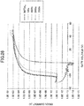
FIG. 16 is a diagram depicting an example of an emission spectrum of a white LED light source used for characterization of the first TFT element. -
FIG. 17 is a diagram depicting an example of an emission spectrum of a fluorescent light used for characterization of the first TFT element. -
FIG. 18 is a diagram showing a result of the characterization under irradiation with light from the white LED light source, obtained for the first TFT element. -
FIG. 19 is a diagram showing a result of the characterization under irradiation with light from the fluorescent light, obtained for the first TFT element. -
FIG. 20 is a chart showing a result of an X-ray diffraction measurement obtained for a second glass substrate sample. -
FIG. 21 is a graph showing a temperature dependence of a mobility obtained from the Hall measurement for the second film in Example 2. -
FIG. 22 is a graph showing a temperature dependence of a carrier density obtained from the Hall measurement for the second film in Example 2. -
FIG. 23 is a diagram showing a result of characterization under irradiation with light from the white LED light source, obtained for a second TFT element. -
FIG. 24 is a diagram showing a result of characterization under irradiation with light from the fluorescent light, obtained for a third TFT element. -
FIG. 25 is a diagram showing another result of the characterization under irradiation with light from the fluorescent light, obtained for the third TFT element. -
FIG. 26 is a diagram showing a result of characterization under irradiation with light from the white LED light source, obtained for a fourth TFT element. -
FIG. 27 is a diagram showing a result of characterization under irradiation with light from the fluorescent light, obtained for the fourth TFT element. - 0017 In the following, with reference to drawings, an embodiment of the present invention will be described. 0018
- An embodiment of the present invention provides an oxide semiconductor compound (in the following, referred to as a "first compound"), including gallium and oxygen, with an optical band gap of 3.4 eV or more, and with an electron Hall mobility of 3 cm2/Vs or more obtained from a Hall measurement at a temperature of 300 K.
- 0019 In the present application, an optical band gap of a material means a value at a room temperature, and is ascertained from the following formula (2):

- 0020 Moreover, an electron Hall mobility and an electron density N can be obtained from a Hall measurement.
- 0021 Note that a temperature dependence of the electron density N is expressed as formula (1):

- 0022 An optical band gap of the first compound is 3.4 eV or more. When the optical band gap is 3.4 eV or more, for an irradiation with visible light, because the optical band gap is greater than a visible light energy, a leak current can be prevented from increasing. The optical band gap is preferably 3.6 eV or more, and further preferably 3.7 eV or more. In the case where the optical band gap is 3.6 eV or more, not only for the irradiation with visible light but also for an irradiation with ultraviolet light, a leak current can be prevented from increasing.
- 0023 Moreover, the electron Hall mobility is 3 cm2/Vs or more. When the electron Hall mobility is 3 cm2/Vs or more, a number of defect levels in the material is small. Thus, in this case, generation of carriers due to defect levels upon irradiation with light can be controlled, and as a result, a leak current can be prevented from increasing. Moreover, when a semiconductor element is formed, a loss of electric voltage is small. The Hall mobility is more preferably 5 cm2/Vs, further preferably 5.5 cm2/Vs, and especially preferably 6 cm2/Vs.
- 0024 Moreover, the constant N0 in formula (1) is preferably 1016 cm-3 or more. When the constant N0 is 1016 cm-3 or more, in the case of using oxide semiconductor for a driving element, when a negative electric voltage is applied, under an environment of irradiation with visible light, a threshold electric voltage can be prevented from shifting in a negative direction, and an OFF operation can be performed. The constant N0 is preferably 1017 cm-3 or more, and further preferably 1018 cm-3 or more. In the case where the constant N0 is 1018 cm-3 or more, when a negative electric voltage is applied, under the environment of irradiation with not only visible light but also ultraviolet light, the threshold electric voltage can be prevented from shifting in the negative direction.
- 0025 The activation energy Ea is preferably 0.04 eV or more. In the case where N0 is 1016 cm-3 or more, by making the activation energy Ea 0.04 eV or more, when a negative electric voltage is applied under the environment of irradiation with visible light, the threshold electric voltage can be prevented from shifting in the negative direction.
- 0026 The activation energy Ea is preferably 0.10 eV or more, and further preferably 0.15 eV or more. In the case where the activation energy Ea is 0.15 eV or more, when a negative electric voltage is applied, under the environment of irradiation with not only visible light but also ultraviolet light, the threshold electric voltage can be prevented from shifting in the negative direction.
- 0027 Moreover, when the first compound has a film shape, a film density falls preferably within a range from 5.0 g/cm-3 to 5.4 g/cm-3. When the film density is 5.0 g/cm-3 or more, the first compound is a dense film, and a high Hall mobility can be obtained. Preferably the film density is 5.1 g/cm-3 or more, and more preferably 5.2 g/cm-3 or more.
- 0028 An absorption coefficient for an incident light energy of 3.5 eV is preferably 10000 cm-1 or less. In the case where the absorption coefficient for the incident light energy of 3.5 eV is 10000 cm-1 or less, because a carrier generation due to an optical excitation decreases, a leak current is small. The absorption coefficient for the incident light energy of 3.5 eV is preferably 5000 cm-1 or less, and further preferably 1000 cm-1 or less.
- 0029 In the case of applying the aforementioned first compound to a semiconductor element such as TFT, a leak current due to the irradiation with light can be controlled. Moreover, a relatively favorable switching characteristic can be obtained.
- 0030 Moreover, even when a negative electric voltage is applied, under the environment of irradiation with light, to a semiconductor element provided with the first compound (in the following, such an environment will be referred to as a "negative electric voltage application light irradiation environment"), a variation is unlikely to occur in a voltage-current characteristic of the semiconductor element. Thus, when the first compound is applied to a semiconductor element, an additional layer such as a conventional light shielding layer becomes unnecessary, and a degree of freedom of the configuration can be greatly enhanced.
- 0031
- Next, an example of a composition of the first compound will be described.
- 0032 The first compound may include, in addition to gallium, another metallic cation.
- 0033 The metallic cation may be, for example, at least one of zinc (Zn), indium (In), tin (Sn) and silicon (Si). Among the metallic cations, particularly, zinc is preferable.
- 0034 Moreover, when the first compound also includes the metallic cation other than gallium, an atomic ratio of gallium atoms to the entirety of metallic cations is preferably 35% or more. When the atomic ratio is 35% or more, for the irradiation with visible light, a leak current can be prevented from increasing. Moreover, a threshold electric voltage is prevented from fluctuating. The atomic ratio of gallium atoms to the entirety of metallic cations is more preferably 50% or more, further preferably 60% or more, and especially preferably 70% or more. In the case where the atomic ratio is 70% or more, when a negative electric voltage is applied, under the environment of irradiation with not only visible light but also ultraviolet light, a leak current can be prevented from increasing, and a threshold electric voltage can be prevented from shifting in the negative direction. The atomic ratio of gallium atoms to the entirety of metallic cations is preferably 95% or less. In the case where the atomic ratio is 95% or less, when a threshold electric voltage is low before irradiating with light, and a negative electric voltage is applied, under the environment of irradiation with not only visible light but also ultraviolet light, a leak current can be prevented from increasing, and the threshold electric voltage can be prevented from shifting in the negative direction.
- 0035 Moreover, for example, when the first compound is configured substantially of oxides of gallium and zinc, the threshold electric voltage can be prevented from increasing, and it is preferable. An atomic ratio of gallium atoms to the entirety of metallic cations (i.e. Ga + Zn) preferably falls within a range from 35% to 95%. When the atomic ratio is 35% or more, the threshold electric voltage is low before irradiating with light, and for the irradiation with visible light, a leak current can be prevented from increasing, and the threshold electric voltage can be prevented from fluctuating. In the case where the atomic ratio is 95% or less, the threshold electric voltage can be prevented from increasing, and the high field effect mobility can be maintained; for the irradiation with visible light, a leak current can be prevented from increasing, and the threshold electric voltage can be prevented from fluctuating. The atomic ratio of gallium atoms to Ga+Zn may be 50% or more, and 70% or more. Moreover, the atomic ratio may be 90% or less, and 85% or less.
- 0036 However, practically, the first compound can include an inevitable material (metal, semiconductor and/or compound) that is not shown in the aforementioned description. Most of the inevitable materials are considered to be mixed into the first compound during a manufacturing process for the first compound. The phrase "configured substantially of oxides of gallium and zinc" means that inevitable materials other than the oxides of gallium and zinc may be included.
- 0037 Note that, the first compound is an amorphous material or an amorphous state may be dominant. The amorphous material is a material that does not give a sharp peak in the X-ray diffraction measurement. Specifically, the amorphous material has a crystallite diameter (Scherrer diameter) obtained by Scherrer's formula, expressed by formula (3), shown below, which is 6 nm or less. A Scherrer diameter L is expressed by

- 0038 Moreover, the phrase "amorphous state may be dominant" means a state in which an amorphous material is present with a volume percent greater than 50%.
- 0039 When amorphous material or an amorphous state is dominant in the first compound, an influence from defect level to grain boundary is small, and variations in electric characteristics is small. The first compound may be microcrystals or may have a form in which an amorphous material and microcrystals are mixed.
- 0040 The term microcrystal means a crystal having a Scherrer diameter greater than 6.0 nm and less than 100 nm. When the first compound is microcrystals, an electrical conductivity is enhanced, and is preferable. When the first compound has the form, in which an amorphous material and microcrystals are mixed, both smoothness and an electrical conductivity are enhanced, and is preferable. 0041
- The first compound having the aforementioned features can be applied to a variety of semiconductor elements, such as a thin-film transistor (TFT), a photovoltaic cell, and an organic light emitting diode (OLED). In the following, with reference to the drawings, an example of such a semiconductor element will be specifically described.
- 0042
-
FIG. 1 is a diagram schematically depicting an example of a cross section of a thin film transistor according to the embodiment (in the following, referred to as a "first element"). - 0043 As illustrated in
FIG. 1 , thefirst element 100 is configured by arranging on asubstrate 110, abarrier film 120, anoxide semiconductor layer 130, agate insulation film 140, aninterlayer insulation film 150, a first electrode (source or drain) 160, a second electrode (drain or source) 162, agate electrode 170, and apassivation film 180. - 0044 The
substrate 110 is an insulation substrate, such as a glass substrate, a ceramic substrate, a plastic substrate, or a resin substrate. Moreover, thesubstrate 110 may be a transparent substrate. - 0045 The
barrier film 120 is arranged between thesubstrate 110 and theoxide semiconductor layer 130, and has a role of forming a backchannel interface of thesubstrate 110 and theoxide semiconductor layer 130. Thebarrier film 120 is configured of silicon oxide, silicon oxynitride, silicon nitride, aluminum oxide and the like. Note that thebarrier film 120 is not indispensable. Thebarrier film 120 may be omitted, if unnecessary. - 0046 The
gate insulation film 140 is configured of an organic insulation material, such as silicon oxide, silicon oxynitride, silicon nitride, and aluminum oxide. The same applies to theinterlayer insulation film 150. - 0047 The first and
second electrodes gate electrode 170 are configured of a metal, such as aluminum, copper and silver, or other electrically conductive material. - 0048 The
passivation film 180 has a role of protecting the element, and configured of silicon oxide, silicon oxynitride, silicon nitride, aluminum oxide and the like. - 0049 In the
first element 100, theoxide semiconductor layer 130 is configured of the first compound having the aforementioned features. - 0050 In the conventional TFT, for the oxide semiconductor layer, for example, a compound such as In-Ga-Zn-O has been used.
- 0051 However, as described above, in the compound, under irradiation with light, a leak current increases. Moreover, in the compound, under the negative electric voltage application light irradiation environment, in addition to the increase of the leak current, the threshold electric voltage may shift in the negative direction. Thus, the OFF operation may not be performed.
- 0052 Thus, in the conventional TFT, in the configuration illustrated in
FIG. 1 , when thesubstrate 110 is transparent, it is necessary to arrange a light shielding layer below theoxide semiconductor layer 130, e.g. between thesubstrate 110 and thebarrier film 120, so that theoxide semiconductor layer 130 is not irradiated with light. Moreover, depending on a size of thegate electrode 170, it is necessary to arrange another light shielding layer also above theoxide semiconductor layer 130, so that theoxide semiconductor layer 130 is not irradiated with light. The light shielding layer means a pattern layer formed of metal or resin, which is not electrically connected to the electrode of the semiconductor element, and shields an incident light. - 0053 The conventional TFT has a problem that the arrangement of such a light shielding layer makes the structure of the element complex, makes the manufacturing process of the element complicated, and restricts the degree of freedom of the configuration of the semiconductor element.
- 0054 In contrast, in the
first element 100, to theoxide semiconductor layer 130, the first compound having the aforementioned features is applied. In this case, even when thefirst element 100 is used under the negative electric voltage application light irradiation environment, the characteristics can be significantly prevented from fluctuating. - 0055 Thus, for the
first element 100, it becomes unnecessary to add the conventional light shielding layer, and the structure of the element and the manufacturing process can be simplified. Moreover, according to the feature, it is possible to significantly enhance the degree of freedom of the configuration of thefirst element 100. - 0056 In the case where a light with a wavelength of 550 nm enters perpendicularly to the
substrate 110 of thefirst element 100 from below thesubstrate 110, when an intensity of the incident light is assumed to be 100, an intensity of a reflected light, which is a light transmitted through thesubstrate 110, theoxide semiconductor layer 130 and thegate insulation film 140, reflected by thegate electrode 170, and transmitted through thegate insulation film 140, theoxide semiconductor layer 130 and thesubstrate 110, is preferably 60 or more. The intensity of the reflected light is more preferably 65 or more, and further preferably 70 or more. - 0057 In the
first element 100, the field effect mobility and the threshold electric voltage of theoxide semiconductor layer 130 are obtained by the following formula (4) in a saturation region of the first element 100:
gate electrode 170 and theoxide semiconductor layer 130, Vgs is an electric voltage between thegate electrode 170 and the source electrode, and Vth is a threshold electric voltage. A coefficient α is, for example, expressed as W/L where a length of a region of theoxide semiconductor layer 130, in which an electric current flows, is L, and a width of the region is W. - 0058 The field effect mobility is, similarly to the aforementioned Hall mobility, proportional to a velocity of a carrier in a constant electric field, and the field effect mobility and the Hall mobility correlate with each other. When the field effect mobility is 5 cm2/Vs or more, a number of defect levels in a material is small. Thus, in this case, generation of carriers due to defect levels upon irradiation with light can be controlled, and as a result, a leak current can be prevented from increasing. Moreover, when a semiconductor element is formed, a loss of electric voltage is small.
- 0059 Moreover, when the field effect mobility of the
oxide semiconductor layer 130 is 5 cm2/Vs or more, the electron Hall mobility obtained by a Hall measurement for theoxide semiconductor layer 130 at 300 K is 3 cm2/Vs or more. - 0060 The field effect mobility of the
oxide semiconductor layer 130 is preferably 5.0 cm2/Vs or more. In the case where the optical band gap of theoxide semiconductor layer 130 is 3.4 eV or more, and the field effect mobility is 5.0 cm2/Vs or more, a leak current can be prevented from increasing under the light irradiation environment or the negative electric voltage application light irradiation environment. The field effect mobility is preferably 6.0 cm2/Vs or more, and more preferably 8.0 cm2/Vs or more. - 0061 The threshold electric voltage is preferably 20 V or lower. For example, when the gate insulation film is configured of SiOx with a film thickness that falls within a range from 75 nm to 150 nm, the threshold electric voltage is 20 V or lower.
- 0062 In the case where the optical band gap of the
oxide semiconductor layer 130 is 3.4 eV or more, the gate insulation film is configured of SiOx, and the film thickness of the gate insulation film falls within a range from 75 nm to 150 nm, by making the threshold electric voltage lower than or equal to 20 V, a leak current can be prevented from increasing and the threshold electric voltage can be prevented from shifting in the negative direction, under the light irradiation environment or the negative electric voltage application light irradiation environment. - 0063 In order to acquire the aforementioned effects, the threshold electric voltage is preferably 20 V or lower, and more preferably 10 V or lower. Moreover, an ON/OFF ratio is preferably 108 to 1010. When the ON/OFF ratio is 108 or more, a screen of cross talk is suppressed on a liquid crystal panel or an OLED panel. The ON/OFF ratio is more preferably 109 or more.
- 0064 The
oxide semiconductor layer 130 is prepared by using a pulsed laser deposition method, or a sputtering method. When the aforementioned method is used, a film with a small number of defects can be obtained, a carrier can be generated even in a deep donor level, the threshold electric voltage becomes 20 V or lower, and the field effect mobility falls within a range from 5.0 cm2/Vs to 8.0 cm2/Vs. Additionally, under the light irradiation environment or the negative electric voltage application light irradiation environment, a carrier due to defect level can be prevented from being generated, and thereby the leak current can be prevented from increasing and the threshold electric voltage can be prevented from shifting in the negative direction. - 0065 Note that, in the example of the
first element 100, illustrated inFIG. 1 , theoxide semiconductor layer 130 is arranged between thesubstrate 110 and thegate electrode 170. - 0066 However, as another example of the thin film transistor (TFT), a reverse-staggered configuration, as illustrated in
FIG. 2 , is considered. - 0067 As illustrated in
FIG. 2 , theTFT 100A is configured by arranging, on asubstrate 110A, abarrier film 120A, agate electrode 170A, agate insulation film 140A, anoxide semiconductor layer 130A, a first electrode (source or drain) 160A, a second electrode (drain or source) 162A, and apassivation film 180A. - 0068 Also in the aforementioned configuration, it is not necessary to shield a part of the
oxide semiconductor layer 130A, that is not covered by thefirst electrode 160A and thesecond electrode 162A. - 0069 In the case where a light with a wavelength of 550 nm enters perpendicularly to the
passivation film 180A of theTFT 100A from above thepassivation film 180A, when an intensity of the incident light is assumed to be 100, an intensity of a reflected light, which is a light transmitted through thepassivation film 180A, theoxide semiconductor layer 130A and thegate insulation film 140A, reflected by thegate electrode 170A, and transmitted through thegate insulation film 140A, theoxide semiconductor layer 130A and thepassivation film 180A, is preferably 60 or more. The intensity of the reflected light is more preferably 65 or more, and further preferably 70 or more. - 0070
- Next, with reference to
FIGS. 3 to 8 , a manufacturing method of thefirst element 100, as illustrated inFIG. 1 , will be described. - 0071 When the
first element 100 is manufactured, thesubstrate 110 is prepared first. - 0072 As described above, the
substrate 110 may be a transparent insulated substrate, such as a glass substrate, a ceramic substrate, a plastic (e.g. polycarbonate or polyethylene terephthalate) substrate, or a resin substrate. Thesubstrate 110 is sufficiently cleansed. - 0073 Next, as necessary, a
barrier film 120 is formed on one surface of thesubstrate 110. - 0074 The
barrier film 120 may be configured of a silicon oxide, a silicon oxynitride, a silicon nitride, aluminum oxide, and the like. Alternatively, as thebarrier film 120, a material having an ultraviolet ray absorption function, such as a zinc oxide, may be used. In this case, an ultraviolet ray entering thefirst element 100 can be absorbed. - 0075 A method of forming the
barrier film 120 is not particularly limited. Thebarrier film 120 may be deposited by using various deposition techniques, such as a sputtering method, a pulsed laser deposition method, an atmospheric CVD method, a decompression CVD method, and a plasma CVD method. A film thickness of thebarrier film 120 preferably falls within a range from 10 nm to 500 nm. - 0076 Note that, as described above, the
barrier film 120 is a layer arranged as necessary, and may be omitted. - 0077 Next, on the barrier film 120 (or the substrate 110), the
oxide semiconductor layer 130 is formed. 0078 - The
oxide semiconductor layer 130 is configured of the aforementioned first compound. A method of forming theoxide semiconductor layer 130 is not particularly limited. For example, theoxide semiconductor layer 130 may be formed from various deposition techniques, such as a sputtering method, a pulsed laser deposition method, an atmospheric CVD method, a decompression CVD method, and a plasma CVD method. - 0079 Note that the deposition of the
oxide semiconductor layer 130 may be performed by using the same apparatus used for the deposition of thebarrier film 120, and successively with the deposition of thebarrier film 120. - 0080 A film thickness of the
oxide semiconductor layer 130 preferably falls within a range from 10 nm to 90 nm. When the film thickness is 10 nm or more, a sufficient electron accumulation layer can be formed. The film thickness of theoxide semiconductor layer 130 is more preferably 20 nm or more, and further preferably 30 nm or more. When the film thickness of theoxide semiconductor layer 130 is 90 nm or less, an electric voltage consumption in the film thickness direction is negligible. The film thickness of theoxide semiconductor layer 130 is more preferably 80 nm or less, and further preferably 60 nm or less. - 0081 Next, the
oxide semiconductor layer 130 is subjected to a pattern processing, and a desired pattern of theoxide semiconductor layer 130 is formed. - 0082 As a method of the pattern processing, a typical method including a mask deposition method, a lift off method and the like may be employed. Moreover, after depositing the
oxide semiconductor layer 130, a resist pattern having an island shape may be arranged above theoxide semiconductor layer 130, and theoxide semiconductor layer 130 may be etched using the resist pattern as a mask. - 0083 In the case of etching the
oxide semiconductor layer 130, as an etchant, an aqueous solution of hydrochloric acid, an aqueous solution of EDTA (ethylene diamine tetra acetate), an aqueous solution of TMAH (tetra methyl ammonium hydride) and the like can be applied. - 0084 The
oxide semiconductor layer 130 is preferably annealed after the pattern processing. An annealing ambience is selected from air, air at reduced pressure, oxygen, hydrogen, nitrogen, an inactive gas, such as argon, helium, and neon, and a water vapor and the like. An annealing temperature preferably falls within a range from 100 °C to 400 °C. When the annealing temperature is 100 °C or higher, the field effect mobility of 5 cm2/Vs or more is obtained. When the annealing temperature is 400 °C or lower, the field effect mobility of theoxide semiconductor layer 130 becomes uniform. The annealing temperature is more preferably 350 °C or lower, and further preferably 300 °C or lower. - 0085
FIG. 3 is a diagram schematically depicting an example of a state in which on thesubstrate 110, thebarrier film 120, and the patternedoxide semiconductor layer 130 are arranged. - 0086 Note that a member in the halfway stage, as illustrated in
FIG. 3 , i.e. a laminated body having theoxide semiconductor layer 130 on thesubstrate 110, can be used as intermediates for various apparatuses and elements, in a variety of fields, in addition to thefirst element 100. - 0087 The aforementioned laminated body may or may not be provided with the
barrier film 120. Theoxide semiconductor layer 130 may or may not be patterned. - 0088 Next, as illustrated in
FIG. 4 , above theoxide semiconductor layer 130, aninsulation film 138 and aconductive film 168 are arranged. - 0089 The
insulation film 138 is configured of a material which will be thegate insulation film 140 later. For example, theinsulation film 138 may be configured of a silicon oxide, a silicon oxynitride, a silicon nitride, aluminum oxide, and the like. Theinsulation film 138 may be deposited by using deposition techniques, such as a sputtering method, a pulsed laser deposition method, an atmospheric CVD method, a decompression CVD method, and a plasma CVD method. - 0090 A thickness of the
insulation film 138 preferably falls within a range from 30 nm to 600 nm. When the thickness of theinsulation film 138 is 30 nm or more, a short circuit between thegate electrode 170 and theoxide semiconductor layer 130, a short circuit between thegate electrode 170 and the first electrode (source or drain) 160, or a short circuit between thegate electrode 170 and the second electrode (drain or source) 162 is controlled. When the thickness of theinsulation film 138 is 600 nm or less, a high ON current is obtained. The thickness of theinsulation film 138 is more preferably 50 nm or more, and further preferably 150 nm or more. Moreover, the thickness of theinsulation film 138 is more preferably 50 nm or less, and further preferably 40 nm or less. - 0091 On the other hand, the
conductive film 168 is configured of a material which will be thegate electrode 170 later. For example theconductive film 168 may be configured of chromium (Cr), molybdenum (Mo), aluminum (Al), copper (Cu), silver (Ag), tantalum (Ta), titanium (Ti) or a composite material including the above-described material and/or an alloy thereof. Theconductive film 168 may be a laminated film. - 0092 Note that in the
first element 100, as described above, because the light shielding for theoxide semiconductor layer 130 is not required, a transparent conductive film may be used for theconductive film 168. The transparent conductive film includes, for example, ITO (In-Sn-O), ZnO, AZO (Al-Zn-O), GZO (Ga-Zn-O), IZO (In-Zn-O) and SnO2. - 0093 The
conductive film 168 may be deposited by using the conventional deposition method, such as a sputtering method and a vapor deposition method. Moreover, theinsulation film 138 and theconductive film 168 may be deposited by the same deposition apparatus successively. - 0094 A film thickness of the
conductive film 168 preferably falls within a range of 30 nm to 600 nm. When the film thickness of theconductive film 168 is 30 nm or more, a low resistance is obtained. When the film thickness is 600 nm or less, a short circuit between theconductive film 168 and the first electrode (source or drain) 160, or a short circuit between theconductive film 168 and the second electrode (drain or source) 162 is controlled. The film thickness of theconductive film 168 is more preferably 50 nm or more, and further preferably 150 nm or more. The film thickness of theconductive film 168 is more preferably 500 nm or less, and further preferably 400 nm or less. - 0095 Next, as illustrated in
FIG. 5 , theinsulation film 138 and theconductive film 168 are subjected to the pattern processing, and thereby thegate insulation film 140 and thegate electrode 170 are formed, respectively. - 0096 For the pattern processing for the
insulation film 138 and theconductive film 168, a method used in a typical TFT array process, i.e. a combination of a photolithography process/etching process, may be employed. - 0097 After the pattern processing for the both layers is completed, for a protrusion part 132 (See
Fig. 5 ) protruding from thegate electrode 170 of theoxide semiconductor layer 130, viewed from above, a process of lowering an electric resistance (resistance lowering process) may be performed. The resistance lowering process can be processed, for example, by using a method of performing a hydrogen plasma treatment for theprotrusion part 132, a method of implanting hydrogen ions into theprotrusion part 132, or the like. - 0098 According to the resistance lowering process for the
protrusion part 132, an ON resistance for TFT can be reduced. - 0099 Next, the
interlayer insulation film 150 is formed above the laminated film. Theinterlayer insulation film 150 may be, as described above, configured of silicon oxide, silicon oxynitride, silicon nitride, aluminum oxide and the like. Theinterlayer insulation film 150 is deposited by using typical deposition techniques, such as a sputtering method, a pulsed laser deposition method, an atmospheric CVD method, a decompression CVD method, and a plasma CVD method. - 0100 Note that, as illustrated in
FIG. 6 , theinterlayer insulation film 150 is subjected to the pattern processing, on both sides of thegate electrode 170 such that parts of theprotrusion part 132 of theoxide semiconductor layer 130 are exposed. For the pattern processing for the interlayer insulation film, a typical combination of photolithography process/etching process may be employed. - 0100 Next, as illustrated in
FIG. 7 , thefirst electrode 160 and thesecond electrode 162 are arranged and patterned. Thefirst electrode 160 and thesecond electrode 162 are, for example, a drain electrode and a source electrode, respectively, or are the source electrode and the drain electrode, respectively. - 0102 The
first electrode 160 and thesecond electrode 162 are arranged and patterned so as to make an ohmic contact with at least a part of theprotrusion part 132 of theoxide semiconductor layer 130. For the pattern processing for thefirst electrode 160 and thesecond electrode 162, a typical combination of a photolithography process/etching process may be employed. - 0103 The
first electrode 160 and thesecond electrode 162 may be configured of chromium, molybdenum, aluminum, copper, silver, tantalum, titanium or a composite material including the above-described material and/or an alloy thereof. Moreover thefirst electrode 160 and thesecond electrode 162 may be a laminated film. Alternatively, thefirst electrode 160 and thesecond electrode 162 can be transparent conductive films, similarly to thegate electrode 170. - 0104 Next, as illustrated in
FIG. 8 , thepassivation film 180 is formed so as to cover the laminated films. Thepassivation film 180 may be configured of silicon oxide, silicon oxynitride, silicon nitride, aluminum oxide, or the like. - 0105 The
passivation film 180 may be deposited by using deposition techniques, such as a sputtering method, a pulsed laser deposition method, an atmospheric CVD method, a decompression CVD method, and a plasma CVD method. - 0106 A thickness of the
passivation film 180 preferably falls within a range from 30 nm to 600 nm. When the thickness of thepassivation film 180 is 30 nm or more, an exposed electrode can be covered. When the thickness is 600 nm or less, a deflection of thesubstrate 110 due to a film stress is small. The thickness of thepassivation film 180 is more preferably 50 nm or more, and further preferably 150 nm or more. Moreover, the thickness of the passivation film is preferably 500 nm or less, and further preferably 400 nm or less. - 0107 According to the aforementioned processes, the
first element 100 can be manufactured. - 0108 Note that the aforementioned manufacturing method is merely an example, and it is apparent for a person skilled in the art that the
first element 100 may also be manufactured by another method. For example, in the case of activating, by thefirst element 100, a liquid crystal or an organic electroluminescent array, in addition to the aforementioned films, an auxiliary capacitance wiring, a terminal, a current compensation circuit and/or the like may be formed. - 0109
- Next, with reference to
FIG. 9 , a configuration of a photovoltaic cell according to the embodiment will be described. - 0110
FIG. 9 is a diagram schematically depicting a cross section of the photovoltaic cell (in the following, referred to as a "second element") according to the embodiment. - 0111 As illustrated in
FIG. 9 , thesecond element 200 is configured by arranging, on asupport 210, asilicon layer 220, anoxide semiconductor layer 230 and anelectrode layer 240. - 0112 The
support 210 has a role of supporting the respective layers above thesupport 210. Thesupport 210 may be configured of, for example, a transparent insulated substrate, such as a glass substrate, a ceramic substrate, a plastic (e.g. polycarbonate or polyethylene terephthalate) substrate, or a resin substrate. - 0113 The
electrode layer 240 is configured of a conductive material such as a metal. - 0114 Note that a manufacturing method of the
second element 200 can be easily understood by referring to the manufacturing method of the aforementionedfirst element 100. Thus, a description of the manufacturing method of thesecond element 200 will be omitted. - 0115 In the
second element 200, theoxide semiconductor layer 230 is configured of the aforementioned first compound. - 0116 Thus, also in the
second element 200, the aforementioned effect is obtained, i.e. even when thesecond element 200 is used under the negative electric voltage application light irradiation environment, the characteristics can be significantly prevented from fluctuating. - 0117
- Next, with reference to
FIG. 10 , a configuration of an organic light emitting diode (OLED) according to the embodiment will be described. - 0118
FIG. 10 is a diagram schematically depicting a cross section of the OLED (in the following, referred to as a "third element") according to the embodiment. - 0119 As illustrated in
FIG. 10 , thethird element 300 is configured by arranging, on asubstrate 310, a first electrode (cathode) 320, anoxide semiconductor layer 330, anorganic layer 340 and a second electrode (anode), in this order. - 0120 The
substrate 310 has a function of supporting the respective layers above thesubstrate 310. Thesubstrate 310 may also be configured of, for example, a transparent insulated substrate, such as a glass substrate, a ceramic substrate, a plastic (e.g. polycarbonate or polyethylene terephthalate) substrate, or a resin substrate. - 0121 The
oxide semiconductor layer 330 has a function of an electron injection layer or an electron transportation layer. - 0122 The
organic layer 340 may include, in addition to an organic light emitting layer, an electron injection layer, an electron transportation layer, the organic light emitting layer, a hole transportation layer, a hole injection layer, and the like. However, if unnecessary, the layers other than the organic light emitting layer may be omitted. - 0123 Note that, in the example illustrated in
FIG. 10 , a surface of thethird element 300 of thesubstrate 310 side is a light extraction surface. Thus, thesubstrate 310 is a transparent substrate, thefirst electrode 320 is a transparent electrode, and theoxide semiconductor layer 330 is a transparent layer. - 0124 Note that a manufacturing method of the
third element 300 can be easily understood by referring to the manufacturing method of the aforementionedfirst element 100. Thus, a description of the manufacturing method of thethird element 300 will be omitted. - 0125 In the
third element 300, theoxide semiconductor layer 330 is configured of the aforementioned first compound. - 0126 Thus, also in the
third element 300, the aforementioned effect is obtained, i.e. even when thethird element 300 is used under the negative electric voltage application light irradiation environment, the characteristics can be significantly prevented from fluctuating. - 0127 As described above, the application form of the first compound has been described with examples of a TFT, a photovoltaic cell and an OLED.
- 0128 However, the aforementioned application form is merely an example. It is clear for a person skilled in the art that the first compound can be applied to other apparatuses or elements. The elements include, for example, a memory element.
- 0129 Next, practical examples of the present invention will be described.
- 0130
- By using a method described as follows, an oxide semiconductor compound containing Ga and Zn as cations was deposited, and characteristics thereof were evaluated.
- 0131 First, pellets for pulsed laser deposition were prepared.
- 0132 The pellets were prepared as follows: Ga2O3 powder (by Kojundo Chemical Laboratory Co., Ltd.) and ZnO powder (by Kojundo Chemical Laboratory Co., Ltd.) were weighted so that a cation atomic percent ratio was Ga:Zn = 70:30, and the powders were mixed in a mortar. From the mixed powder, green compacts were formed.
- 0133 The green compacts were baked in atmospheric air and at 1400 °C for five hours, and pellets each having a diameter of 15 mm and a height of 8 mm (in the following, referred to as "first pellets") were obtained.
- 0134 By using the first pellets, using the pulsed laser deposition method, a thin film was deposited on a substrate. For the substrate, two kinds of substrates, i.e. a glass substrate (AN100, by AGC Inc.) and a quartz glass substrate were used.
- 0135 The deposition was performed by attaching the first pellet to a pellet holder in a vacuum chamber accommodating the substrate, and irradiating the pellet with a laser pulse. For a laser light, a KrF laser with a wavelength of 248 nm (Complex Pro 110F by Coherent, Inc.) was used. An input power was set to 60 mJ, a repetition frequency was set to 10 Hz. Note that an inside of the chamber was an oxygen atmosphere, and an oxygen partial pressure was set to 5 Pa. A temperature of the substrate was set to 26 °C.
- 0136 According to the above-described configuration, an oxide film including Ga and Zn with a thickness of 150 nm was formed on the substrate.
- 0137 Afterwards, under a vacuum environment (3×10⁻³ Pa) at 200 °C for an hour, the substrate was annealed. Thus, a glass substrate having an oxide film (in the following, referred to as a "first glass substrate sample"), and a quartz glass substrate having an oxide film (in the following, referred to as a "first quartz glass substrate sample") were obtained.
- 0138 In order to obtain a ratio of Ga to Zn in the oxide film, a fluorescent X-ray analysis was performed by using the first glass substrate sample. For the analysis, a fluorescent X-ray measurement apparatus (ZSX100e by Rigaku Corporation) was used.
- 0139 Results of the analysis showed that the ratio of Ga to Zn was the same as a composition of the first pellet. That is, a composition of the oxide film was Ga:Zn = 70:30 (atomic ratio). In the following, the oxide film obtained by the aforementioned deposition method will be referred to as a "first film". Note that the composition of the first film is expressed by Ga0.7Zn0.3Ox.
- 0140 Next, a crystallinity and an optical band gap of the first film were evaluated.
- 0141 The evaluation of the crystallinity was performed by an X-ray diffraction measurement for the first glass substrate sample. For the measurement apparatus, Smart Lab (9 kW) by Rigaku Corporation was used. 0142
-
FIG. 11 shows results of the X-ray diffraction measurement obtained for the first glass substrate sample. From the results, it is found that in the first glass substrate sample, only a broad halo pattern is present. The Scherrer diameter obtained from the aforementioned formula (3) was 1.5 nm, and it was identified that the first film was amorphous. - 0143 Next, using the first quartz glass substrate sample, the optical band gap was evaluated.
- 0144 First, by using a spectrophotometer (U-4100 by Hitachi, Ltd.), a transmissivity T (%) and a reflectance R (%) of the first quartz glass substrate sample were measured.
- 0145 From the results of measurements, by using the following formula (5), an absorption coefficient α of the first film was calculated:

- 0146
FIG. 12 shows an absorption coefficient of the first film calculated by using the formula (5). The absorption coefficient of the first film, when the incident light energy was 3.5 eV, was 990 cm-1. - 0147 When the first film is amorphous, the following formula (6) gives a relation between the absorption coefficient α and an energy of light:

- 0148 Thus, when a square root of αhν has a linear relation to hv, from the formula (6), the optical band gap of the first film can be calculated. The optical band gap of the first film was 3.76 eV.
- 0149 Next, by the aforementioned Hall measurement for the first quartz glass substrate sample, a carrier density and a mobility of the first film were evaluated.
- 0150 Before the Hall measurement, at four corners of the first film of the first quartz glass substrate sample, AI patterns (2 mm × 2 mm) with a thickness of 50 nm were formed, and used as electrodes.
- 0151 For the Hall measurement, a Hall measurement apparatus (ResiTest 8300 by TOYO Corporation) was used. An intensity of a magnetic field was set to 0.34 T, and for measuring an electric current, an automatically setting mode was used. The measurement was performed for each 10 K within a range from 160 K to 300 K.
- 0152
FIG. 13 shows a temperature dependence of a Hall mobility obtained by the Hall measurement. Moreover,FIG. 14 shows a temperature dependence of a carrier density obtained by the Hall measurement. Note that in any case, the carrier was an electron. - 0153 From
FIG. 13 andFIG. 14 , it was found that both carrier (electron) mobility and the carrier (electron) density closely followed the Arrhenius Law. The carrier (electron) mobility at 300 K was 6.9 cm2/Vs. - 0154 From the temperature dependence of the carrier (electron) density N, obtained as above, based on the aforementioned formula (1), No and the activation energy Ea were obtained. N0 was 1.5 × 1018 cm-3, and the activation energy was Ea = 0.16 eV.
- 0155 Moreover, using Smartlab by Rigaku Corporation, by an XRR method, a film density of the first film was measured. As a result, the film density was 5.25 g/cm3. 0156
- Next, by the following method, a TFT element (in the following, referred to as a "first TFT sample") was prepared.
- 0157
FIG. 15 is a diagram schematically depicting a cross-sectional configuration of the first TFT sample. 0158 - As illustrated in
FIG. 15 , thefirst TFT sample 400 includes asilicon substrate 410, athermal oxidation film 420, anoxide semiconductor layer 430, adrain electrode 440 and asource electrode 450. - 0159 For preparing the
first TFT sample 400, first, the silicon substrate 410 (13 mm × 13 mm) with thethermal oxidation film 420 was provided. Thesilicon substrate 410 was n-type, and has a specific resistance of 0.001 Ωcm. Thethermal oxidation film 420 was formed by oxidizing thesilicon substrate 410. A thickness of thethermal oxidation film 420 was 150 nm. - 0160 Note that, the
silicon substrate 410 was used as a gate electrode of thefirst TFT sample 400, and thethermal oxidation film 420 was used as a gate insulation film of thefirst TFT sample 400. - 0161 Next, a photoresist was arranged on the
thermal oxidation film 420. Moreover, by a typical photolithography method, the photoresist was subjected to a pattern processing. A pattern of the photoresist was set to a shape in which a rectangular through region of 900 µm (vertical) × 300 µm (horizontal) (length in the X-direction inFIG. 15 ) was present at the center. - 0162 Next, by a pulsed laser deposition method, using the photoresist as a mask, an oxide semiconductor layer was formed on the
thermal oxidation film 420. - 0163 The oxide semiconductor was set to be a layer containing oxides of Ga and Zn, and deposited with the deposition condition shown in the aforementioned item (evaluation of first film). However, the thickness of the oxide semiconductor layer was set to 50 nm.
- 0164 Afterwards, the
silicon substrate 410 was immersed in an acetone, and was subjected to an ultrasonic cleansing for five minutes. Furthermore, thesilicon substrate 410 was subjected to another ultrasonic cleansing for five minutes in an ethanol. According to the above-described processing, the photoresist and the oxide semiconductor layer deposited on the photoresist were removed. As a result, anoxide semiconductor layer 430 having an island shape was formed at the center of thethermal oxidation film 420. - 0165 Next, the
silicon substrate 410 was annealed for one hour at 200 °C, under the reduced pressure of 3.0 × 10⁻³ Pa. - 0166 Next, on the
thermal oxidation film 420 and theoxide semiconductor layer 430, thedrain electrode 440 and thesource electrode 450, having shapes illustrated inFIG. 15 , were formed. - 0167 The
electrodes - 0168 In the top plan view, dimensions of the
drain electrode 440 and thesource electrode 450 were set to be 300 µm (vertical) × 200 µm (horizontal) (length in the X-direction inFIG. 15 ) × 50 nm (thickness)(maximum). Moreover, a distance Lt between thedrain electrode 440 and the source electrode 450 (SeeFIG. 15 ) was set to be 50 µm. - 0169 Finally, an end surface of the
silicon substrate 410 was polished so that a conductive surface was exposed. The exposed surface was set to be an electric conductive part. - 0170 According to the aforementioned processes, the
first TFT sample 400 was prepared. Note that from the above descriptions, it is clear that theoxide semiconductor layer 430 of thefirst TFT sample 400 corresponds to the aforementioned "first film". 0171 - Using the
first TFT sample 400, prepared as above, a characteristic evaluation under the negative electric voltage application light irradiation environment was performed. - 0172 Specifically, in a state where the
first TFT sample 400 was irradiated with light from a side opposite to thesilicon substrate 410, and a negative electric voltage was applied to the gate electrode (silicon substrate 410), a change in characteristics occurring in thefirst TFT sample 400 was measured. - 0173 For the measurement of the change in characteristics, a semiconductor parameter analyzer (4155C by Agilent Technologies Inc.) was used. For a light source, a white LED light source and a fluorescent light attached to the prober were used. An illuminance of the white LED light source was 11000 lux, and an illuminance of the fluorescent light was 17000 lux.
- 0174
FIG. 16 shows an emission spectrum of the white LED light source used for the measurement. Moreover,FIG. 17 shows an emission spectrum of the fluorescent light used for the measurement. - 0175 In the evaluation of characteristics, under the irradiation with light from the light source, the gate electrode was set to -20 V, and the
drain electrode 440 and thesource electrode 450 were set to 0 V. After maintaining the state for a predetermined time period, the TFT characteristics were measured. - 0176
FIGS. 18 and19 show results of the evaluation obtained for thefirst TFT sample 400.FIG. 18 shows results under irradiation with light from the white LED light source, andFIG. 19 shows results under irradiation with light from the fluorescent light. - 0177 Note that in the figures, a line denoted by "INITIAL" indicates a measurement result for a dark state, i.e. a state without the irradiation with light.
- 0178 From
FIGS. 18 and19 , it is found that, in the case of thefirst TFT sample 400 that is provided with the first film as theoxide semiconductor layer 430, even after maintaining for 7200 seconds under the negative electric voltage application light irradiation environment, the characteristics are almost unchanged. Moreover, it is found that the result does not depend on a type of the light source. - 0179 In this way, it is confirmed that the characteristics of the first film haying a composition expressed by Ga0.7Zn0.3Ox is significantly prevented from fluctuating even under the negative electric voltage application light irradiation environment.
- 0180 Note that an ON/OFF ratio of the
first TFT sample 400 in the dark state was from 108 to 109, the field effect mobility of theoxide semiconductor layer 430 calculated from the saturation region was 7.1 cm2/Vs, and the threshold electric voltage was 0 V. - 0181
- Using the same method as in Example 1, an oxide semiconductor compound including Ga and Zn as cations was deposited, and characteristics thereof were evaluated.
- 0182 However, in Example 2, when the pellets for pulsed laser deposition were prepared, Ga2O3 powder (by Kojundo Chemical Laboratory Co., Ltd.) and ZnO powder (by Kojundo Chemical Laboratory Co., Ltd.) were weighted so that a cation atomic percent ratio was Ga:Zn = 35:65, and the powders were mixed. The other conditions for preparing pellets are the same as the case of Example 1. According to the above-described processes, second pellets were obtained.
- 0183 By using the second pellets, under the same condition as in the case of Example 1, by the pulsed laser deposition method, a thin film was deposited on the glass substrate and the quartz glass substrate. Afterwards, the respective substrates were annealed under the aforementioned condition.
- 0184 According to the above-described processes, on the two kinds of substrates, oxide films containing Ga and Zn, with a thickness of 150 nm were formed. In the following, the glass substrate having the oxide film will be referred to as a "second glass substrate sample" and the quartz glass substrate having the oxide film will be referred to as a "second quartz glass substrate sample".
- 0185 Using the second glass substrate sample, a ratio between Ga and Zn in the oxide film was evaluated by the fluorescent X-ray analysis. The results of evaluation showed that the ratio between Ga and Zn was the same as the composition of the second pellets. That is, the composition of the oxide film was Ga:Zn = 35:65 (in atomic ratio). In the following, the film obtained in the aforementioned deposition method will be referred to as a "second film". Note that the composition of the second film is expressed by Ga0.35Zn0.65Oy.
- 0186 Next, a crystallinity of the second film was evaluated using the same method as in Example 1. 0187
-
FIG. 20 shows results of an X-ray diffraction measurement obtained for the second glass substrate sample. From the results it is found that in the second glass substrate sample, only a broad halo pattern is present. The Scherrer diameter obtained from the aforementioned formula (3) was 1.3 nm, and it was identified that the second film was amorphous. - 0188 Next, from the aforementioned formula (5), an absorption coefficient of the second film was evaluated.
FIG. 12 shows the absorption coefficient of the second film. The absorption coefficient of the second film for the incident light energy of 3.5 eV was 3062 cm-1. Moreover, from the formula (6), an optical band gap of the second film was evaluated. As a result, the optical band gap of the second film was calculated to be 3.47 eV. - 0189 Next, by a Hall measurement for the second quartz glass substrate sample, a carrier density and a mobility of the second film were evaluated. The method of the Hall measurement was the same as in Example 1. 0190
-
FIG. 21 shows a temperature dependence of the mobility obtained by the Hall measurement. Moreover,FIG. 22 shows a temperature dependence of the carrier density obtained by the Hall measurement. Note that in any case, the carrier was an electron. - 0191 From
FIG. 21 andFIG. 22 , it was found that both carrier (electron) mobility and the carrier (electron) density closely followed the Arrhenius Law. The carrier (electron) mobility at 300 K was 5.9 cm2/Vs. - 0192 From the temperature dependence of the carrier (electron) density N, obtained as above, based on the aforementioned formula (1), N0 and the activation energy Ea were obtained. N0 was 1.0 × 1018 cm-3, and the activation energy was Ea = 0.04 eV.
- 0193 Moreover, using Smartlab by Rigaku Corporation, by an XRR method, a film density of the second film was measured. As a result, the film density was 5.25 g/cm3. 0194
- Next, by the same method as in Example 1, a TFT element (in the following, referred to as a "second TFT sample") was prepared. However, in Example 2, for the oxide semiconductor layer, the second film was used. The deposition method for the film was described in the aforementioned section of "Evaluation of second film". 0195
- Using the second TFT sample, a characteristic evaluation under the negative electric voltage application light irradiation environment was performed, as in the case in Example 1.
- 0196
FIG. 23 shows results of evaluation obtained for the second TFT sample. For a light source, a white LED light having the spectrum intensity, as shown inFIG. 16 , was used. Note that inFIG. 23 , a line denoted by "INITIAL" indicates a measurement result for the dark state, i.e. a state without the irradiation with light. - 0197 From
FIG. 23 , it is found that, in the case of the second TFT sample that is provided with the second film as the oxide semiconductor layer, the threshold electric voltage shifts, and the OFF electric current increases slightly. However, because the threshold electric current converges at about -5 V, when the gate off electric voltage is set to -25 V, for example, the second TFT sample can be used as a switching element even under the light irradiation environment. - 0198 In this way, it is confirmed that the characteristics of the second film having a composition expressed by Ga0.35Zn0.65Oy are significantly prevented from fluctuating even under the negative electric voltage application light irradiation environment.
- 0199 Note that the ON/OFF ratio of the second TFT sample in the dark state was 109, the field effect mobility of the oxide semiconductor layer calculated from a saturation region was 5.5 cm2/Vs, and the threshold electric voltage was -1.1 V.
- 0200
- Using the following method, an oxide semiconductor compound including Ga and Zn as cations was deposited, and characteristics thereof were evaluated. For the deposition method, a sputtering method was employed. For the target, an oxide target, of which the molar ratio between Ga2O3 and ZnO was Ga2O3:ZnO = 50:50, was purchased from Toshima Manufacturing Co., Ltd.
- 0201 Using the target, by the sputtering method, a thin film was deposited on a substrate. The substrate was a glass substrate and a quartz glass substrate.
- 0202 The deposition was performed for the substrate and the target arranged in a vacuum chamber by the sputtering method. For a sputter power source, a radiofrequency (RF) power supply of 13.56 MHz was used. An atmosphere was a mixed gas atmosphere of an Ar gas and an O2 gas. A flow rate of the Ar gas was 39.9 sccm and a flow rate of the O2 gas was 0.1 sccm. A pressure was 1 Pa, and an electric power was 150 W. Furthermore, a distance between the substrate and the target was 100 mm.
- 0203 According to the above-described process, on each of the two kinds of substrates, an oxide film containing Ga and Zn was formed. In the following, the glass substrate having the oxide film will be referred to as a "third glass substrate sample", and the quartz glass substrate having the oxide film will be referred to as a "third quartz glass substrate sample".
- 0204 Note that a thickness of the oxide film on the third glass substrate sample was 200 nm. On the other hand, a thickness of the oxide film on the third quartz glass substrate sample was 50 nm.
- 0205 In order to examine a ratio between Ga and Zn in the oxide film obtained as above, by the same method as in the case of Example 1, a fluorescent X-ray analysis was performed.
- 0206 As a result of the analysis, a molar ratio of Ga/(Zn+Ga) was 65%. That is, the composition of the oxide film was Ga:Zn = 65:35 (atomic ratio). In the following, the oxide film obtained by the aforementioned deposition method will be referred to as a "third film". Note that the composition of the third film is expressed by Ga0.65Zn0.35Oz.
- 0207 Next, from the aforementioned formula (6), an optical band gap of the third film was evaluated. As a result, the optical band gap of the third film was calculated to be 3.90 eV.
- 0208 Moreover, the Hall mobility of the third film at 300 K was 4.82 cm2/Vs.
- 0209 Furthermore, using Smartlab by Rigaku Corporation, by an XRR method, a film density of the third film was measured. As a result, the film density was 5.36 g/cm3.
- 0210
- Next, by the same method as in Example 1, a TFT element (in the following, referred to as a "third TFT sample") was prepared.
- 0211 However, in Example 3, for the oxide semiconductor layer, the third film was used. The deposition method for the film was described in the aforementioned section of "Evaluation of third film". Moreover, in Example 3, the TFT element, prepared as above, was subjected to a surface treatment. The surface treatment was performed by immersing the TFT element in an aqueous solution of tetramethylammoniumhydride (TMAH) of 2.38% for three seconds.
- 0212 According to the above-described processes, the third TFT sample was prepared.
- 0213
- Using the third TFT sample, a characteristic evaluation under the negative electric voltage application light irradiation environment was performed, as in the case in Example 1.
- 0214
FIG. 24 shows results of the evaluation obtained for the third TFT sample. For a light source, a fluorescent light having the spectrum intensity, as shown inFIG. 17 , was used. Note that inFIG. 24 , a line denoted by "INITIAL" indicates a characteristic measurement result for the dark state, i.e. a state without the irradiation with light. Moreover, a line denoted by "LIGHTING FLUORESCENT LIGHT" indicates a characteristic measurement result for a state with the irradiation with light. In the latter case, the source electric voltage was 0 V, and the drain electric voltage was 40 V. - 0215
FIG. 25 shows a chronological change in an electric current value of the third TFT sample during driving under the irradiation with light from a fluorescent light. A driving condition for the third TFT sample was that the gate electric voltage was -30 V, the drain electric voltage was 10 V, and the source electric voltage was 0 V. - 0216 From
FIGS. 24 and25 , it is found that, in the case of the third TFT sample, even under the environment of irradiation with light, almost no shift of the threshold electric voltage or almost no increase of the OFF current can be observed. - 0217 In this way, it is confirmed that the characteristics of the third film having a composition expressed by Ga0.65Zn0.35Oz are significantly prevented from fluctuating even under the negative electric voltage application light irradiation environment.
- 0218 Note that the ON/OFF ratio of the third TFT sample in the dark state was 1010, the field effect mobility of the oxide semiconductor layer calculated from a saturation region was 8.04 cm2/Vs, and the threshold electric voltage was 19.0 V.
- 0219
- By using a method described as follows, an oxide semiconductor compound containing In, Ga and Zn as cations was deposited, and characteristics thereof were evaluated.
- 0220 First, a target for sputtering was prepared.
- 0221 The target was prepared as follows: In2O3 powder (by Kojundo Chemical Laboratory Co., Ltd.), Ga2O3 powder (by Kojundo Chemical Laboratory Co., Ltd.) and ZnO powder (by Kojundo Chemical Laboratory Co., Ltd.) were weighted so that a molar ratio was In2O3:Ga2O3:ZnO = 1:1:2, and the powders were mixed in a mortar. From the mixed powder, a green compact was formed.
- 0222 The green compact was baked in atmospheric air and at 1400 °C for five hours, and the target having a diameter of 76.2 mm and a height of 8 mm was obtained.
- 0223 Using the target, by the sputtering method, a thin film was deposited on a substrate. For the substrate, a glass substrate and a quartz glass substrate were used.
- 0224 The deposition was performed for the substrate and the target arranged in a vacuum chamber by the sputtering method. For a sputter power source, a radiofrequency (RF) power supply of 13.56 MHz was used. An atmosphere was a mixed gas atmosphere of an Ar gas and an O2 gas. A flow rate of the Ar gas was 19.6 sccm and a flow rate of the O2 gas was 0.4 sccm. A pressure was 0.55 Pa, and an electric power was 70 W. Furthermore, a distance between the substrate and the target was 100 mm.
- 0225 After the deposition, the substrate was annealed at 300 °C, for one hour, under an atmosphere of pure oxygen.
- 0226 According to the above-described process, on the substrate, an oxide film containing In, Ga and Zn with a thickness of about 30 nm was formed. In the following, the glass substrate having the oxide film will be referred to as a "fourth glass substrate sample", and the quartz glass substrate having the oxide film will be referred to as a "fourth quartz glass substrate sample".
- 0227 In order to examine percentages of Ga and Zn in the oxide film of the fourth glass substrate sample obtained as above, by the same method as in the case of Example 1, a fluorescent X-ray analysis was performed.
- 0228 As a result of the analysis, atomic percentages of In, Ga and Zn were 40%, 36% and 24%, respectively. In the following, the oxide film obtained by the aforementioned deposition method will be referred to as a "fourth film".
- 0229 From the aforementioned formula (5), an absorption coefficient of the fourth film was evaluated.
FIG. 12 shows the absorption coefficient of the fourth film. The absorption coefficient of the fourth film for the incident light energy of 3.5 eV was 30023 cm-1. Moreover, from the formula (6), an optical band gap of the fourth film was evaluated. As a result, the optical band gap of the fourth film was calculated to be 3.1 eV. - 0230 Next, by a Hall measurement for the fourth quartz glass substrate sample, a carrier density and a mobility of the fourth film were evaluated. The method of the Hall measurement was the same as in Example 1.
- 0231 The results of measurement showed that the carrier was an electron, and that both the carrier (electron) mobility and the carrier (electron) density closely followed the Arrhenius Law. The activation energy Ea calculated based on the aforementioned formula (1) was 0.05 eV, and N0 was 8.0 × 1015 cm-3. Moreover, the carrier (electron) mobility at 300 K was 5.9 cm2/Vs.
- 0232
- Next, by the same method as in Example 3, a TFT element (in the following, referred to as a "fourth TFT sample") was prepared.
- 0233 However, in Example 4, for the oxide semiconductor layer, the fourth film was used. The deposition method for the film was described in the aforementioned section of "Evaluation of fourth film". 0234
- Using the fourth TFT sample, a characteristic evaluation under the negative electric voltage application light irradiation environment was performed, as in the case in Example 1.
- 0235
FIGS. 26 and27 show results of the evaluation obtained for the fourth TFT sample.FIG. 26 shows results of the evaluation under irradiation with light from a white LED light source, andFIG. 27 shows results of the evaluation under irradiation with light from a fluorescent light. - 0236 Note that in
FIGS. 26 and27 , lines denoted by "INITIAL" indicate characteristic measurement results for the dark state, i.e. a state without the irradiation with light. - 0237 From
FIGS. 26 and27 , it is found that, in the case of the fourth TFT sample that is provided with the fourth film as the oxide semiconductor layer, under the negative electric voltage application light irradiation environment, and independent of a type of the light source, the characteristics fluctuate significantly. - 0238 Particularly, in the case of using the white LED light source for the light source, it was found from
FIG. 26 that a leak current from the fourth TFT sample exceeds 100 pA under the negative electric voltage application light irradiation environment. Additionally, in the case of using the fluorescent light for the light source, it was found fromFIG. 27 that an amount of shift of the threshold electric voltage and the leak current were greater than those in the case of using the white LED light source for the light source, and thereby the characteristics were further degraded. - 0239 In this way, it was found that in the fourth TFT sample, which did not have the oxide semiconductor layer according to the embodiment of the present invention, the characteristics were degraded significantly, under the negative electric voltage application light irradiation environment. In contrast, it was found that in the TFT element, which was provided with the oxide semiconductor layer according to the embodiment of the present invention (first to third TFT samples), the characteristics were prevented from being significantly degraded under the negative electric voltage application light irradiation environment.
- 0240 The present application is based on and claims the benefit of priority of Japanese Priority Application No.
2016-040498 filed on March 2, 2016 - 0241
- 100
- TFT (first element)
- 110
- substrate
- 120
- barrier film
- 130
- oxide semiconductor layer
- 132
- protrusion part
- 138
- insulation film
- 140
- gate insulation film
- 150
- interlayer insulation film
- 160
- first electrode
- 162
- second electrode
- 168
- conductive film
- 170
- gate electrode
- 180
- passivation film
- 200
- photovoltaic cell (second element)
- 210
- support
- 220
- silicon layer
- 230
- oxide semiconductor layer
- 240
- electrode layer
- 300
- OLED (third element)
- 310
- substrate
- 320
- first electrode (cathode)
- 330
- oxide semiconductor layer
- 340
- organic layer
- 350
- second electrode (anode)
- 400
- first TFT sample
- 410
- silicon substrate
- 420
- thermal oxidation film
- 430
- oxide semiconductor layer
- 440
- drain electrode
- 450
- source electrode
Claims (17)
- An oxide semiconductor compound comprising:gallium; andoxygen,wherein an optical band gap is 3.4 eV or more, andwherein an electron Hall mobility obtained by performing a Hall measurement at a temperature of 300 K is 3 cm2/Vs or more.
- The oxide semiconductor compound according to claim 1,
wherein when a temperature dependence of an electron density N obtained from the Hall measurement is expressed by a formula:
- The oxide semiconductor compound according to claim 2,
wherein the activation energy Ea is 0.04 eV or more. - The oxide semiconductor compound according to any one of claims 1 to 3,
wherein an absorption coefficient for an incident light energy of 3.5 eV is 10000 cm-1 or less. - The oxide semiconductor compound according to any one of claims 1 to 4 further comprising zinc.
- The oxide semiconductor compound according to any one of claims 1 to 5,
wherein an atomic ratio of gallium atoms to an entirety of metallic cations is 35% or more. - The oxide semiconductor compound according to any one of claims 1 to 6 practically consisting of gallium oxide and zinc oxide.
- The oxide semiconductor compound according to claim 7,
wherein an atomic ratio of gallium atoms to a whole amount of gallium atoms and zinc atoms falls within a range from 35% to 95%. - The oxide semiconductor compound according to any one of claims 1 to 8 is an amorphous material.
- A semiconductor element comprising a layer of an oxide semiconductor compound,
wherein the semiconductor element is any one of a thin film transistor (TFT), a photovoltaic cell, and an organic light emitting diode (OLED), and
wherein the layer is configured of the oxide semiconductor compound according to any one of claims 1 to 9. - The semiconductor element according to claim 10,
wherein the semiconductor element is a TFT, and
wherein the layer has a field effect mobility of 5 cm2/Vs or more. - A semiconductor element comprising a layer of an oxide semiconductor compound,
wherein the semiconductor element is a thin film transistor (TFT), and
wherein the layer includes gallium and oxygen, has an optical band gap of 3.4 eV or more, and has a field effect mobility of 5 cm2/Vs or more. - The semiconductor element according to any one of claims 10 to 12,
wherein the semiconductor element includes a substrate;
the layer arranged above the substrate;
a gate electrode arranged above the layer; and
a source electrode and a drain electrode being in contact with the layer, and
wherein the layer is not shielded by a light shielding layer on a side of the substrate. - The semiconductor element according to any one of claims 10 to 12,
wherein the semiconductor element includes
a substrate;
a gate electrode arranged above the substrate; the layer arranged above the gate electrode; and
a source electrode and a drain electrode being in contact with the layer, and
wherein the layer is not shielded by a light shielding layer on a side opposite to the substrate and the gate electrode. - A laminated body comprising:a substrate; anda layer of an oxide semiconductor compound arranged above the substrate,wherein the layer is configured of the oxide semiconductor compound according to any one of claims 1 to 9.
- The laminated body according to claim 15 further comprising a barrier film between the substrate and the layer.
- The laminated body according to claim 15 or 16,
wherein the substrate is a glass substrate.
Applications Claiming Priority (2)
| Application Number | Priority Date | Filing Date | Title |
|---|---|---|---|
| JP2016040498 | 2016-03-02 | ||
| PCT/JP2017/006939 WO2017150351A1 (en) | 2016-03-02 | 2017-02-23 | Oxide semiconductor compound, semiconductor element having layer of oxide semiconductor compound, and laminate |
Publications (2)
| Publication Number | Publication Date |
|---|---|
| EP3425678A1 true EP3425678A1 (en) | 2019-01-09 |
| EP3425678A4 EP3425678A4 (en) | 2019-10-09 |
Family
ID=59744137
Family Applications (1)
| Application Number | Title | Priority Date | Filing Date |
|---|---|---|---|
| EP17759817.4A Withdrawn EP3425678A4 (en) | 2016-03-02 | 2017-02-23 | OXIDE SEMICONDUCTOR COMPOUND, SEMICONDUCTOR ELEMENT COMPRISING A LAYER OF OXIDE SEMICONDUCTOR COMPOUND, AND LAMINATE |
Country Status (7)
| Country | Link |
|---|---|
| US (1) | US11075303B2 (en) |
| EP (1) | EP3425678A4 (en) |
| JP (1) | JP7130209B2 (en) |
| KR (1) | KR20180121892A (en) |
| CN (1) | CN109075205A (en) |
| TW (1) | TWI732828B (en) |
| WO (1) | WO2017150351A1 (en) |
Families Citing this family (2)
| Publication number | Priority date | Publication date | Assignee | Title |
|---|---|---|---|---|
| WO2020218354A1 (en) * | 2019-04-25 | 2020-10-29 | Agc株式会社 | Nanoparticle aggregate, nanoparticle dispersion liquid, ink, thin film, organic light emitting diode, and nanoparticle aggregate manufacturing method |
| CN114342086A (en) * | 2019-07-12 | 2022-04-12 | 株式会社Flosfia | Oxide semiconductor film and semiconductor device |
Family Cites Families (28)
| Publication number | Priority date | Publication date | Assignee | Title |
|---|---|---|---|---|
| JPS5589030A (en) | 1978-12-20 | 1980-07-05 | Towa Seiki Kk | Automatic feeder for overlapped cups |
| JP4068308B2 (en) | 2000-02-10 | 2008-03-26 | Tdk株式会社 | Optical information medium |
| EP2413366B1 (en) * | 2004-03-12 | 2017-01-11 | Japan Science And Technology Agency | A switching element of LCDs or organic EL displays |
| US7297977B2 (en) * | 2004-03-12 | 2007-11-20 | Hewlett-Packard Development Company, L.P. | Semiconductor device |
| RU2369940C2 (en) | 2004-11-10 | 2009-10-10 | Кэнон Кабусики Кайся | Amorphous oxide and field-effect transistor using said oxide |
| US7791072B2 (en) * | 2004-11-10 | 2010-09-07 | Canon Kabushiki Kaisha | Display |
| EP1815530B1 (en) * | 2004-11-10 | 2021-02-17 | Canon Kabushiki Kaisha | Field effect transistor employing an amorphous oxide |
| JP5037808B2 (en) | 2005-10-20 | 2012-10-03 | キヤノン株式会社 | Field effect transistor using amorphous oxide, and display device using the transistor |
| JP5395994B2 (en) * | 2005-11-18 | 2014-01-22 | 出光興産株式会社 | Semiconductor thin film, manufacturing method thereof, and thin film transistor |
| JP2007250982A (en) * | 2006-03-17 | 2007-09-27 | Canon Inc | Thin film transistor and display device using oxide semiconductor |
| KR100785038B1 (en) * | 2006-04-17 | 2007-12-12 | 삼성전자주식회사 | Amorphous ZnO based Thin Film Transistor |
| JP2009123957A (en) | 2007-11-15 | 2009-06-04 | Sumitomo Chemical Co Ltd | Oxide semiconductor material, manufacturing method thereof, electronic device, and field effect transistor |
| WO2009091013A1 (en) * | 2008-01-17 | 2009-07-23 | Idemitsu Kosan Co., Ltd. | Field effect transistor, semiconductor device and semiconductor device manufacturing method |
| JP2011066375A (en) * | 2009-08-18 | 2011-03-31 | Fujifilm Corp | Amorphous oxide semiconductor material, field-effect transistor, and display device |
| JP2012033854A (en) * | 2010-04-20 | 2012-02-16 | Kobe Steel Ltd | Oxide for semiconductor layer of thin film transistor, sputtering target, and thin film transistor |
| WO2012017843A1 (en) * | 2010-08-06 | 2012-02-09 | Semiconductor Energy Laboratory Co., Ltd. | Semiconductor integrated circuit |
| JP5626978B2 (en) * | 2010-09-08 | 2014-11-19 | 富士フイルム株式会社 | THIN FILM TRANSISTOR, MANUFACTURING METHOD THEREOF, AND APPARATUS HAVING THE THIN FILM TRANSISTOR |
| JP5701015B2 (en) * | 2010-11-08 | 2015-04-15 | キヤノン株式会社 | Driving method of semiconductor device |
| JP2012235104A (en) * | 2011-04-22 | 2012-11-29 | Kobe Steel Ltd | Thin film transistor structure, and thin film transistor and display device including the structure |
| KR101891650B1 (en) * | 2011-09-22 | 2018-08-27 | 삼성디스플레이 주식회사 | OXIDE SEMICONDUCTOR, THIN FILM TRANSISTOR INCLUDING THE SAME AND THIN FILM TRANSISTOR array PANEL INCLUDING THE SAME |
| TWI562361B (en) * | 2012-02-02 | 2016-12-11 | Semiconductor Energy Lab Co Ltd | Semiconductor device |
| KR101352537B1 (en) * | 2012-06-08 | 2014-01-21 | 한국과학기술연구원 | Se or S based thin film solar cell and method for fabricating the same |
| US20140021464A1 (en) * | 2012-07-17 | 2014-01-23 | National Chung Cheng University | Yttrium-doped Indium Oxide Transparent Conductive Thin-Film Transistor and Method for Making Same |
| TW201427027A (en) * | 2012-12-26 | 2014-07-01 | Hon Hai Prec Ind Co Ltd | Thin film transistor |
| KR20250028503A (en) | 2012-12-28 | 2025-02-28 | 가부시키가이샤 한도오따이 에네루기 켄큐쇼 | Semiconductor device and manufacturing method thereof |
| JP2015109315A (en) * | 2013-12-03 | 2015-06-11 | 出光興産株式会社 | THIN FILM TRANSISTOR, MANUFACTURING METHOD THEREOF, OXIDE SEMICONDUCTOR LAYER, DISPLAY DEVICE AND SEMICONDUCTOR DEVICE |
| KR102281399B1 (en) | 2013-12-26 | 2021-07-23 | 고쿠리츠다이가쿠호진 토쿄고교 다이가꾸 | Metal oxide thin film, organic electroluminescence element provided with thin film, solar cell, and organic solar cell |
| JP2018032839A (en) * | 2015-12-11 | 2018-03-01 | 株式会社半導体エネルギー研究所 | Transistor, circuit, semiconductor device, display device, and electronic apparatus |
-
2017
- 2017-02-23 JP JP2018503092A patent/JP7130209B2/en active Active
- 2017-02-23 EP EP17759817.4A patent/EP3425678A4/en not_active Withdrawn
- 2017-02-23 CN CN201780014378.9A patent/CN109075205A/en active Pending
- 2017-02-23 KR KR1020187024762A patent/KR20180121892A/en not_active Withdrawn
- 2017-02-23 WO PCT/JP2017/006939 patent/WO2017150351A1/en not_active Ceased
- 2017-03-01 TW TW106106613A patent/TWI732828B/en not_active IP Right Cessation
-
2018
- 2018-08-30 US US16/117,761 patent/US11075303B2/en not_active Expired - Fee Related
Also Published As
| Publication number | Publication date |
|---|---|
| EP3425678A4 (en) | 2019-10-09 |
| US11075303B2 (en) | 2021-07-27 |
| CN109075205A (en) | 2018-12-21 |
| US20180374959A1 (en) | 2018-12-27 |
| WO2017150351A1 (en) | 2017-09-08 |
| KR20180121892A (en) | 2018-11-09 |
| TWI732828B (en) | 2021-07-11 |
| JP7130209B2 (en) | 2022-09-05 |
| JPWO2017150351A1 (en) | 2019-01-10 |
| TW201732885A (en) | 2017-09-16 |
Similar Documents
| Publication | Publication Date | Title |
|---|---|---|
| KR101510581B1 (en) | Thin film transistor structure, and thin film transistor and display device provided with said structure | |
| KR101459983B1 (en) | Oxide for semiconductor layer of thin-film transistor, sputtering target, and thin-film transistor | |
| KR101536491B1 (en) | Interconnect structure and sputtering target | |
| Oh et al. | Improving the gate stability of ZnO thin-film transistors with aluminum oxide dielectric layers | |
| US9178076B2 (en) | Thin-film transistor | |
| JP5718072B2 (en) | Thin film transistor oxide for semiconductor layer and sputtering target, and thin film transistor | |
| KR20130097809A (en) | Oxide for semiconductor layer of thin film transistor, sputtering target, and thin-film transistor | |
| KR101775803B1 (en) | Evaluation method for oxide semiconductor thin film, quality control method for oxide semiconductor thin film, and evaluation element and evaluation device used in said evaluation method | |
| KR102124867B1 (en) | Oxide for semiconductor layer of thin-film transistor, sputtering target, and thin-film transistor | |
| KR101626241B1 (en) | Oxide for semiconductor layer in thin-film transistor, thin-film transistor, display device, and sputtering target | |
| KR20130018300A (en) | Oxide for semiconductor layer of thin-film transistor, sputtering target, and thin-film transistor | |
| TW201202452A (en) | Oxide for semiconductor layer of thin film transistor, sputtering target, and thin film transistor | |
| US20160035895A1 (en) | Oxide semiconductor target, oxide semiconductor film and method for producing same, and thin film transistor | |
| WO2014061638A1 (en) | Thin film transistor | |
| US11075303B2 (en) | Oxide semiconductor compound, semiconductor element provided with layer of oxide semiconductor compound, and laminated body | |
| TWI486466B (en) | An oxide thin film, a thin film transistor, and a display device for a semiconductor layer of a thin film transistor | |
| Ochi et al. | Improvement of stress stability in back channel etch-type amorphous In-Ga-Zn-O thin film transistors with post process annealing | |
| JP5965107B2 (en) | Thin film transistor | |
| US20200287002A1 (en) | Semiconductor compound, semiconductor device and laminate having layer of semiconductor compound, and target | |
| JP7384777B2 (en) | Oxide semiconductor thin films, thin film transistors and sputtering targets | |
| KR20200076128A (en) | Method for Preparing Oxide Thin Transistor |
Legal Events
| Date | Code | Title | Description |
|---|---|---|---|
| STAA | Information on the status of an ep patent application or granted ep patent |
Free format text: STATUS: THE INTERNATIONAL PUBLICATION HAS BEEN MADE |
|
| PUAI | Public reference made under article 153(3) epc to a published international application that has entered the european phase |
Free format text: ORIGINAL CODE: 0009012 |
|
| STAA | Information on the status of an ep patent application or granted ep patent |
Free format text: STATUS: REQUEST FOR EXAMINATION WAS MADE |
|
| 17P | Request for examination filed |
Effective date: 20180906 |
|
| AK | Designated contracting states |
Kind code of ref document: A1 Designated state(s): AL AT BE BG CH CY CZ DE DK EE ES FI FR GB GR HR HU IE IS IT LI LT LU LV MC MK MT NL NO PL PT RO RS SE SI SK SM TR |
|
| AX | Request for extension of the european patent |
Extension state: BA ME |
|
| DAV | Request for validation of the european patent (deleted) | ||
| DAX | Request for extension of the european patent (deleted) | ||
| A4 | Supplementary search report drawn up and despatched |
Effective date: 20190909 |
|
| RIC1 | Information provided on ipc code assigned before grant |
Ipc: H01L 29/786 20060101AFI20190903BHEP |
|
| STAA | Information on the status of an ep patent application or granted ep patent |
Free format text: STATUS: THE APPLICATION IS DEEMED TO BE WITHDRAWN |
|
| 18D | Application deemed to be withdrawn |
Effective date: 20200603 |