EP3425603A1 - Aircraft-mounted external fire detection system - Google Patents
Aircraft-mounted external fire detection system Download PDFInfo
- Publication number
- EP3425603A1 EP3425603A1 EP18181607.5A EP18181607A EP3425603A1 EP 3425603 A1 EP3425603 A1 EP 3425603A1 EP 18181607 A EP18181607 A EP 18181607A EP 3425603 A1 EP3425603 A1 EP 3425603A1
- Authority
- EP
- European Patent Office
- Prior art keywords
- aircraft
- operator terminal
- engine nacelle
- fire
- detection system
- Prior art date
- Legal status (The legal status is an assumption and is not a legal conclusion. Google has not performed a legal analysis and makes no representation as to the accuracy of the status listed.)
- Granted
Links
Images



Classifications
-
- G—PHYSICS
- G08—SIGNALLING
- G08B—SIGNALLING SYSTEMS, e.g. PERSONAL CALLING SYSTEMS; ORDER TELEGRAPHS; ALARM SYSTEMS
- G08B17/00—Fire alarms; Alarms responsive to explosion
-
- G—PHYSICS
- G01—MEASURING; TESTING
- G01J—MEASUREMENT OF INTENSITY, VELOCITY, SPECTRAL CONTENT, POLARISATION, PHASE OR PULSE CHARACTERISTICS OF INFRARED, VISIBLE OR ULTRAVIOLET LIGHT; COLORIMETRY; RADIATION PYROMETRY
- G01J5/00—Radiation pyrometry, e.g. infrared or optical thermometry
- G01J5/0088—Radiation pyrometry, e.g. infrared or optical thermometry in turbines
-
- B—PERFORMING OPERATIONS; TRANSPORTING
- B64—AIRCRAFT; AVIATION; COSMONAUTICS
- B64D—EQUIPMENT FOR FITTING IN OR TO AIRCRAFT; FLIGHT SUITS; PARACHUTES; ARRANGEMENT OR MOUNTING OF POWER PLANTS OR PROPULSION TRANSMISSIONS IN AIRCRAFT
- B64D45/00—Aircraft indicators or protectors not otherwise provided for
-
- B—PERFORMING OPERATIONS; TRANSPORTING
- B64—AIRCRAFT; AVIATION; COSMONAUTICS
- B64D—EQUIPMENT FOR FITTING IN OR TO AIRCRAFT; FLIGHT SUITS; PARACHUTES; ARRANGEMENT OR MOUNTING OF POWER PLANTS OR PROPULSION TRANSMISSIONS IN AIRCRAFT
- B64D47/00—Equipment not otherwise provided for
-
- G—PHYSICS
- G08—SIGNALLING
- G08B—SIGNALLING SYSTEMS, e.g. PERSONAL CALLING SYSTEMS; ORDER TELEGRAPHS; ALARM SYSTEMS
- G08B17/00—Fire alarms; Alarms responsive to explosion
- G08B17/12—Actuation by presence of radiation or particles, e.g. of infrared radiation or of ions
-
- G—PHYSICS
- G08—SIGNALLING
- G08B—SIGNALLING SYSTEMS, e.g. PERSONAL CALLING SYSTEMS; ORDER TELEGRAPHS; ALARM SYSTEMS
- G08B17/00—Fire alarms; Alarms responsive to explosion
- G08B17/12—Actuation by presence of radiation or particles, e.g. of infrared radiation or of ions
- G08B17/125—Actuation by presence of radiation or particles, e.g. of infrared radiation or of ions by using a video camera to detect fire or smoke
-
- B—PERFORMING OPERATIONS; TRANSPORTING
- B64—AIRCRAFT; AVIATION; COSMONAUTICS
- B64D—EQUIPMENT FOR FITTING IN OR TO AIRCRAFT; FLIGHT SUITS; PARACHUTES; ARRANGEMENT OR MOUNTING OF POWER PLANTS OR PROPULSION TRANSMISSIONS IN AIRCRAFT
- B64D45/00—Aircraft indicators or protectors not otherwise provided for
- B64D2045/009—Fire detection or protection; Erosion protection, e.g. from airborne particles
-
- B—PERFORMING OPERATIONS; TRANSPORTING
- B64—AIRCRAFT; AVIATION; COSMONAUTICS
- B64D—EQUIPMENT FOR FITTING IN OR TO AIRCRAFT; FLIGHT SUITS; PARACHUTES; ARRANGEMENT OR MOUNTING OF POWER PLANTS OR PROPULSION TRANSMISSIONS IN AIRCRAFT
- B64D33/00—Arrangement in aircraft of power plant parts or auxiliaries not otherwise provided for
-
- G—PHYSICS
- G01—MEASURING; TESTING
- G01J—MEASUREMENT OF INTENSITY, VELOCITY, SPECTRAL CONTENT, POLARISATION, PHASE OR PULSE CHARACTERISTICS OF INFRARED, VISIBLE OR ULTRAVIOLET LIGHT; COLORIMETRY; RADIATION PYROMETRY
- G01J5/00—Radiation pyrometry, e.g. infrared or optical thermometry
- G01J2005/0077—Imaging
-
- G—PHYSICS
- G01—MEASURING; TESTING
- G01J—MEASUREMENT OF INTENSITY, VELOCITY, SPECTRAL CONTENT, POLARISATION, PHASE OR PULSE CHARACTERISTICS OF INFRARED, VISIBLE OR ULTRAVIOLET LIGHT; COLORIMETRY; RADIATION PYROMETRY
- G01J3/00—Spectrometry; Spectrophotometry; Monochromators; Measuring colours
- G01J3/02—Details
- G01J3/0264—Electrical interface; User interface
-
- G—PHYSICS
- G01—MEASURING; TESTING
- G01J—MEASUREMENT OF INTENSITY, VELOCITY, SPECTRAL CONTENT, POLARISATION, PHASE OR PULSE CHARACTERISTICS OF INFRARED, VISIBLE OR ULTRAVIOLET LIGHT; COLORIMETRY; RADIATION PYROMETRY
- G01J3/00—Spectrometry; Spectrophotometry; Monochromators; Measuring colours
- G01J3/02—Details
- G01J3/027—Control of working procedures of a spectrometer; Failure detection; Bandwidth calculation
-
- G—PHYSICS
- G01—MEASURING; TESTING
- G01J—MEASUREMENT OF INTENSITY, VELOCITY, SPECTRAL CONTENT, POLARISATION, PHASE OR PULSE CHARACTERISTICS OF INFRARED, VISIBLE OR ULTRAVIOLET LIGHT; COLORIMETRY; RADIATION PYROMETRY
- G01J3/00—Spectrometry; Spectrophotometry; Monochromators; Measuring colours
- G01J3/02—Details
- G01J3/0289—Field-of-view determination; Aiming or pointing of a spectrometer; Adjusting alignment; Encoding angular position; Size of measurement area; Position tracking
-
- G—PHYSICS
- G01—MEASURING; TESTING
- G01J—MEASUREMENT OF INTENSITY, VELOCITY, SPECTRAL CONTENT, POLARISATION, PHASE OR PULSE CHARACTERISTICS OF INFRARED, VISIBLE OR ULTRAVIOLET LIGHT; COLORIMETRY; RADIATION PYROMETRY
- G01J3/00—Spectrometry; Spectrophotometry; Monochromators; Measuring colours
- G01J3/28—Investigating the spectrum
- G01J3/2803—Investigating the spectrum using photoelectric array detector
-
- G—PHYSICS
- G01—MEASURING; TESTING
- G01J—MEASUREMENT OF INTENSITY, VELOCITY, SPECTRAL CONTENT, POLARISATION, PHASE OR PULSE CHARACTERISTICS OF INFRARED, VISIBLE OR ULTRAVIOLET LIGHT; COLORIMETRY; RADIATION PYROMETRY
- G01J5/00—Radiation pyrometry, e.g. infrared or optical thermometry
- G01J5/0014—Radiation pyrometry, e.g. infrared or optical thermometry for sensing the radiation from gases, flames
- G01J5/0018—Flames, plasma or welding
-
- G—PHYSICS
- G01—MEASURING; TESTING
- G01J—MEASUREMENT OF INTENSITY, VELOCITY, SPECTRAL CONTENT, POLARISATION, PHASE OR PULSE CHARACTERISTICS OF INFRARED, VISIBLE OR ULTRAVIOLET LIGHT; COLORIMETRY; RADIATION PYROMETRY
- G01J5/00—Radiation pyrometry, e.g. infrared or optical thermometry
- G01J5/60—Radiation pyrometry, e.g. infrared or optical thermometry using determination of colour temperature
- G01J5/602—Radiation pyrometry, e.g. infrared or optical thermometry using determination of colour temperature using selective, monochromatic or bandpass filtering
Definitions
- the present disclosure generally relates to the field of fire detection systems, and more particularly to the field of aircraft-mounted external fire detection systems.
- Jet aircraft commonly house one or more engines in respective nacelles. These nacelles are commonly mounted under a wing of the aircraft.
- Engine fire detectors are often located within specific fire zones inside of the engine/nacelle arrangement. Such fire zones typically include the area between the engine case and the inner wall of the nacelle, around the engine fan case and/or the engine core. These detectors allow the flight crew to be alerted in the event that fire exists within that volume, i.e., external to the engine but within the nacelle compartment.
- an aircraft-mounted external fire detection system comprises optical circuitry mounted on an aircraft.
- the optical circuitry is configured to optically monitor an exterior of the engine nacelle for a hydrocarbon fire by detecting radiation outside of the visible light spectrum.
- the aircraft-mounted external fire detection system also comprises processing circuitry, which is communicatively coupled to the optical circuitry.
- the processing circuitry is configured to use the optical circuitry to determine that the fire has been continuously present for more than a threshold duration, and trigger an appropriate response (e.g., transmit a warning to an operator terminal of the aircraft).
- the aircraft may be capable of being manned (e.g., via the operator terminal).
- the aircraft may be capable of operating unmanned.
- the aircraft may be capable of spaceflight, may be a rotorcraft, may comprise a rocket and/or may be any other form of airborne vehicle comprising an engine-nacelle arrangement.
- a method implemented in an aircraft-mounted external fire detection system comprises optically monitoring an exterior of an engine nacelle of an aircraft for a hydrocarbon fire by detecting radiation outside of the visible light spectrum using optical circuitry mounted on the aircraft aft of the engine nacelle. The method further comprises using the optical circuitry to determine that the fire has been continuously present for more than a threshold duration, and in response, transmitting a warning to an operator terminal of the aircraft.
- the optical circuitry may have a field of view comprising a perimeter substantially defined by a maximum expected deflection of the engine nacelle relative to the optical circuitry under maneuvering load of the aircraft such that the exterior of the engine nacelle remains within the field of view during the maneuvering load.
- Transmitting the warning to the operator terminal may comprise controlling the operator terminal to display video of the engine nacelle.
- Controlling the operator terminal to display video of the engine nacelle may comprise triggering the operator terminal to display video captured from a ground maneuvering camera system mounted on the aircraft and to which the operator terminal is communicatively connected.
- controlling the operator terminal to display video of the engine nacelle may be responsive to determining that at least a threshold number of displays are operative at the operator terminal.
- Transmitting the warning to the operator terminal may comprise controlling the operator terminal to display a notification that is distinct from a further notification produced by a different fire detection system that monitors for fire inside of the engine nacelle.
- the method may further comprise receiving a warning suppression signal from the operator terminal, and in response, refraining from sending a further warning to the operator terminal until determining that the fire is no longer present and subsequently determining that another fire has been continuously present for more than the threshold duration.
- the method may further comprise optically monitoring the exterior of the engine nacelle for the fire by detecting radiation outside of the visible light spectrum using additional optical circuitry mounted on the aircraft aft of the engine nacelle, and refraining from transmitting the warning to the operator terminal until it is also determined that the fire has been continuously present for more than the threshold duration using the additional optical circuitry.
- the optical circuitry may be mounted on a vertical or horizontal stabilizer of the aircraft.
- an aircraft-mounted external fire detection system comprises optical circuitry mounted on an aircraft aft of an engine nacelle of the aircraft.
- the aircraft-mounted external fire detection system further comprises processing circuitry communicatively coupled to the optical circuitry.
- the optical circuitry is configured to optically monitor an exterior of the engine nacelle for a hydrocarbon fire by detecting radiation outside of the visible light spectrum.
- the processing circuitry is configured to use the optical circuitry to determine that the fire has been continuously present for more than a threshold duration, and in response, transmit a warning to an operator terminal of the aircraft.
- the optical circuitry may have a field of view comprising a perimeter substantially defined by a maximum expected deflection of the engine nacelle relative to the optical circuitry under maneuvering load of the aircraft such that the exterior of the engine nacelle remains within the field of view during the maneuvering load.
- the processing circuitry may be configured to control the operator terminal to display video of the engine nacelle.
- the processing circuitry may be configured to trigger the operator terminal to display video captured by a ground maneuvering camera system mounted on the aircraft to which the operator terminal is communicatively connected.
- the processing circuitry may be configured to control the operator terminal to display video of the engine nacelle responsive to determining that at least a threshold number of displays are operative at the operator terminal.
- the processing circuitry may be configured to control the operator terminal to display a notification that is distinct from a further notification produced by a different fire detection system that monitors for fire inside of the engine nacelle.
- the processing circuitry may be further configured to receive a warning suppression signal from the operator terminal, and in response, refrain from sending a further warning to the operator terminal until the processing circuitry determines that the fire is no longer present and subsequently determines that another fire has been continuously present for more than the threshold duration.
- the aircraft-mounted external fire detection system may further comprise additional optical circuitry mounted on the aircraft aft of the engine nacelle.
- the additional optical circuitry may be configured to optically monitor the exterior of the engine nacelle for the fire by detecting radiation outside of the visible light spectrum.
- the processing circuitry may be further configured to refrain from transmitting the warning to the operator terminal until the processing circuitry also determines that the fire has been continuously present for more than the threshold duration using the additional optical circuitry.
- the optical circuitry may be mounted on a vertical or horizontal stabilizer of the aircraft.
- the aircraft-mounted external fire detection system may be configured to perform any of the methods described herein, e.g., via appropriate configuration of the processing circuitry.
- This disclosure further provides systems, computer program products, and/or software that correspond to one or more of the methods described herein.
- a non-transitory computer readable medium storing a computer program product for controlling a programmable aircraft-mounted external fire detection system
- the computer program product comprises software instructions that, when executed on processing circuitry of the programmable aircraft-mounted external fire detection system, cause the processing circuitry to: use optical circuitry, mounted on an aircraft aft of an engine nacelle of the aircraft and configured to optically monitor an exterior of the engine nacelle for a hydrocarbon fire by detecting radiation outside of the visible light spectrum, to determine that the fire has been continuously present for more than a threshold duration; and transmit a warning to an operator terminal of the aircraft in response to the determination.
- the software instructions may cause the processing circuitry to transmit the warning to the operator terminal by controlling the operator terminal to display a notification that is distinct from a further notification produced for a different fire detection system that monitors for fire inside of the engine nacelle, the notification comprising video captured by a ground maneuvering camera system mounted on the aircraft to which the operator terminal is communicatively connected.
- a non-transitory computer readable medium storing a computer program product for controlling a programmable aircraft-mounted external fire detection system
- the computer program product comprises software instructions that, when executed on processing circuitry of the programmable aircraft-mounted external fire detection system, cause the processing circuitry to perform any of the methods described above.
- a computer program product for controlling a programmable aircraft-mounted external fire detection system comprises software instructions that, when executed on processing circuitry of the programmable aircraft-mounted external fire detection system, cause the processing circuitry to: use optical circuitry, mounted on an aircraft aft of an engine nacelle of the aircraft and configured to optically monitor an exterior of the engine nacelle for a hydrocarbon fire by detecting radiation outside of the visible light spectrum, to determine that the fire has been continuously present for more than a threshold duration; and transmit a warning to an operator terminal of the aircraft in response to the determination.
- a computer program product for controlling a programmable aircraft-mounted external fire detection system comprises software instructions that, when executed on processing circuitry of the programmable aircraft-mounted external fire detection system, cause the processing circuitry to perform any of the methods described above.
- the present disclosure is directed to methods, apparatuses, systems, computer program products, and/or software for aircraft-mounted external fire detection.
- Traditional aircraft engine fire detection systems do not provide any information regarding whether or not a fire is outside the nacelle wall of an engine/nacelle arrangement.
- Traditional aircraft engine fire detection systems also do not provide any indication of a fire originating within the engine gas path, such as a tailpipe fire.
- an aircraft-mounted external fire detection system addresses one or more shortcomings of traditional aircraft engine fire detection systems by, among other things, optically monitoring an exterior of an engine nacelle.
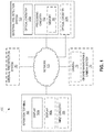
- FIG. 1 illustrates an example network environment 100 according to an example of the disclosure.
- the example network environment 100 comprises an external fire detection system 130 and an operator terminal 150 communicatively connected to each other via a network 105.
- the network 105 includes one or more physical devices and/or signaling mediums capable of exchanging communication signals between the external fire detection system 130 and the operator terminal 150. Examples of such a network 105 include (but are not limited to) one or more signaling mediums; one or more local area networks; one or more wireless networks; one or more Internet Protocol-based networks; one or more Ethernet networks; one or more optical networks; one or more ad hoc networks; and/or one or more electrical buses.
- Such a network 105 may comprise any number of networking devices such as routers, gateways, switches, hubs, firewalls, multiplexers, controllers, and the like (not shown) supporting the exchange of such communication signals.
- the external fire detection system 130 comprises optical circuitry 120a and processing circuitry 110.
- the optical circuitry 120a is configured to optically monitor for a hydrocarbon fire by detecting radiation outside of the visible light spectrum (i.e., ultraviolet and/or infrared radiation).
- the optical circuitry 120a may be configured to detect a particular wavelength of infrared radiation that is produced in abundance during the burning of a hydrocarbon, such as jet fuel and/or oil.
- Such optical circuitry 120a may rely on the particular radiation wavelength emitted by a given byproduct of hydrocarbon combustion. For example, hot carbon dioxide produced from the burning of a given hydrocarbon may produce significant amounts of infrared radiation at approximately 4.3 micrometers relative to the surrounding ambient air.
- the optical circuitry 120a may be configured to trigger a signal in response to a spike in radiation at 4.3 micrometers in wavelength occurring within a particular field of view of the optical circuitry 120a. According to other examples, the optical circuitry 120a detects and responds to radiation at one or more other wavelengths. In a particular example, the optical circuitry 120a is a solar-blind optical flame detector.
- the processing circuitry 110 is communicatively coupled to the optical circuitry 120a.
- the processing circuitry 110 comprises one or more microprocessors, microcontrollers, hardware circuits, discrete logic circuits, hardware registers, digital signal processors (DSPs), field-programmable gate arrays (FPGAs), application-specific integrated circuits (ASICs), memory, or a combination thereof.
- the processing circuitry 110 includes programmable hardware capable of executing software instructions stored, e.g., in memory 190 as a machine-readable computer program.
- Examples of such memory 190 include any non-transitory machine-readable media known in the art or that may be developed, whether volatile or non-volatile, including (but not limited to) solid state media (e.g., SRAM, DRAM, DDRAM, ROM, PROM, EPROM, flash memory, solid state drive, etc.), removable storage devices (e.g., Secure Digital (SD) card, miniSD card, microSD card, memory stick, thumb-drive, USB flash drive, ROM cartridge, Universal Media Disc), fixed drive (e.g., magnetic hard disk drive), or the like, individually or in any combination.
- solid state media e.g., SRAM, DRAM, DDRAM, ROM, PROM, EPROM, flash memory, solid state drive, etc.
- removable storage devices e.g., Secure Digital (SD) card, miniSD card, microSD card, memory stick, thumb-drive, USB flash drive, ROM cartridge, Universal Media Disc
- fixed drive e.g., magnetic hard disk drive
- the processing circuitry 110 is configured to use the optical circuitry 120a to determine whether to transmit a warning to the operator terminal 150 via the network 105. In particular, the processing circuitry 110 transmits a warning to the operator terminal 150 in response to determining that the fire has been continuously present for more than a threshold duration (e.g., three seconds; five seconds).
- the threshold duration may be such that minor flare-ups of exhaust gas and/or ingested objects (e.g., birds) from the engine nacelle and/or fires on the ground moving quickly past the field of view of the optical circuitry 120a are inadequate to cause the processing circuitry 110 to transmit the warning.
- the threshold duration is one of a plurality of predefined durations with which the processing circuitry 110 is configured.
- the threshold duration may be of a smaller or larger duration (e.g., three or five seconds) based on whether the processing circuitry 110 is configured to a more or less sensitive fire detection mode, respectively.
- the processing circuitry 110 is configurable through an appropriate control signal sent from the operator terminal 150.
- the determination that the fire has been continuously present is based on a steady or periodic signal received from the optical circuitry 120a.
- Other examples determine that the fire has been continuously present based on a different use of the optical circuitry 120a.
- the external fire detection system 130 comprises additional optical circuitry 120b.
- the additional optical circuitry 120b is also configured to optically monitor the exterior of an engine nacelle for a hydrocarbon fire by detecting radiation outside of the visible light spectrum.
- the engine nacelle monitored by optical circuitry 120b is same as that which is monitored by optical circuitry 120a, and in other examples, the engine nacelle monitored by optical circuitry 120b is different.
- the processing circuitry is further configured to refrain from transmitting the warning to the operator terminal 150 until the processing circuitry 110 not only determines that the fire has been continuously present for more than the threshold duration using the optical circuitry 120a, but also determines that the fire has been continuously present for more than the threshold duration using the additional optical circuitry 120b.
- the use of optical circuitry 120a and optical circuitry 120b to monitor the same engine nacelle may improve the detection of the hydrocarbon fire and/or reduce false positive fire detection results, e.g., by optically monitoring the same engine nacelle from different positions. In particular example, at least one of these positions is an aft-mounted position.
- various examples of the present disclosure include external fire detection systems 130 that optically monitor each of one, some, or all of the engine nacelles on the aircraft from any number of viewpoints, each being mounted with corresponding optical circuitry 120.
- the warning transmitted by the processing circuitry 110 controls the operator terminal 150 to display a notification of the fire, e.g., in a manner conspicuous to an operator of the aircraft, such as a pilot or other aircrew member, on a display 160a of the operator terminal 150.
- a display 160a includes a telltale, an annunciator panel, a multi-function display (MFD), a touchscreen display, a Liquid Crystal Display (LCD), and/or a Light Emitting Diode (LED) display.
- the processing circuitry 110 controls the operator terminal 150 to display an engine-indicating and crew-alerting system (EICAS) warning and/or a Master Warning indication on such a display 160a.
- EICAS engine-indicating and crew-alerting system
- the operator terminal 150 further includes input circuitry 195 for accepting input from an operator (e.g., a pilot).
- the input circuitry 195 includes one or more of: a pointing device (e.g., a mouse, stylus, touchpad, trackball, pointing stick, joystick), a microphone (e.g., for speech input), an optical sensor (e.g., for optical recognition of gestures), and/or pushkeys (e.g., a keyboard, number-pad, and/or function keys).
- a pointing device e.g., a mouse, stylus, touchpad, trackball, pointing stick, joystick
- a microphone e.g., for speech input
- an optical sensor e.g., for optical recognition of gestures
- pushkeys e.g., a keyboard, number-pad, and/or function keys.
- the interface circuitry 195 is implemented as a unitary physical component, or as a plurality of physical components that are contiguously or separately arranged, any of which may be communicatively coupled to any other, or may communicate with any other via an appropriate signaling medium (e.g., network 105).
- an appropriate signaling medium e.g., network 105
- the network environment 100 further comprises an internal fire detection system 180 that is communicatively connected to the network 105 and is distinct from the external fire detection system 130.
- the internal fire detection system 180 monitors for fire inside of the engine nacelle.
- the notification displayed by the operator terminal 150 responsive to the warning from the external fire detection system 130 may be distinct from a further notification produced for the internal fire detection system 180.
- the notification displayed by the operator terminal 150 responsive to the warning is distinct from a flight deck fire switch and fuel cutoff lever corresponding to the engine nacelle experiencing the external fire.
- Such an example may, e.g., enable an operator to distinguish between external and internal nacelle fires (e.g., between a fire in the exhaust gas path and a fire in the engine core), such that the operator may make a correspondingly appropriate response.
- an internal engine fire may be addressed by cutting fuel to the engine and activating a fire suppression system (not shown), whereas an external fire may be addressed by merely reducing engine throttle and/or changing the fuel mixture to reduce the amount of flammable exhaust being produced from the engine nacelle.
- the network environment 100 includes a camera 175, and the warning transmitted by the processing circuitry 110 controls the operator terminal 150 to display video of the engine nacelle captured by the camera 175.
- the camera 175 is an optical device that treats radiation emitted by the hydrocarbon fire in a manner that is consistent with radiation not emitted by the hydrocarbon fire (i.e., in contrast to the optical circuitry 120). Accordingly, an operator may be afforded with a view of the engine nacelle in response to the external fire detection system 130 detecting the hydrocarbon fire.
- the ability to view video of the engine nacelle may enable an operator of the aircraft to determine the severity of the fire and determine whether the warning produced by the external fire detection system 130 is a false positive fire detection result, and/or determine whether to land, turnback, and/or evacuate the aircraft.
- a ground maneuvering camera system 170 is comprised in the network environment 100, and the camera 175 is comprised in the ground maneuvering camera system 170.
- a ground maneuvering camera system 170 is a camera system that includes at least one camera 175 and is commonly used to give an operator of the aircraft a real-time view of areas in proximity to the aircraft (e.g., the landing gear, engine nacelles, and the ground underneath) for use in taxing.
- the processing circuitry 110 is configured to trigger the operator terminal 150 to display video captured by the ground maneuvering camera system 170 mounted on the aircraft and to which the operator terminal 150 is communicatively connected, i.e., via network 105.
- the operator terminal 150 comprises a plurality of displays, e.g., display 160a and display 160b.
- the processing circuitry 110 is configured to control the operator terminal 150 to display video of the engine nacelle responsive to determining that at least a threshold number of displays 160a, 160b are operative at the operator terminal 150. For example, in response to the processing circuitry 110 determining that only display 160a is operative (e.g., due to display 160b being inoperative), the processing circuitry 110 may refrain from controlling the operator terminal 150 to display video captured by camera 175. Such an example may prevent one of the few (or the only) display 160 in operation at operator terminal 150 from being commandeered by the external fire detection system 130 (which may be in use for displaying other critical information to the pilot, for example).
- the processing circuitry 110 is further configured to receive a warning suppression signal from the operator terminal 150, and in response, refrain from sending a further warning to the operator terminal 150 until the processing circuitry 110 determines that the fire is no longer present and subsequently determines that another fire has been continuously present for more than the threshold duration.
- the warning suppression signal may be triggered via the operator terminal 150 by an operator of the aircraft who has determined that the fire warning is the result of a false positive and wishes to prevent being further distracted by a corresponding notification on the display 160a.
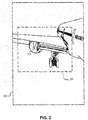
- Figure 2 illustrates an example frame of video captured from the perspective of a camera 175 of a ground maneuvering camera system 170 mounted aft of an engine nacelle 210, according to an example of the present disclosure.
- the camera 175 captures video within a field of view 290 that includes that engine nacelle 210.
- the optical circuitry 120a is configured with a field of view 220 with which to optically monitor the engine nacelle 210. As shown in Figure 2 , the field of view 220 of the optical circuitry 120a is narrower than the field of view 290 of the camera 175, yet large enough to include outboard and inboard sides of the engine nacelle 210 (i.e., no portion of the engine nacelle 210 is outside of the perimeter of the field of view 220.
- the optical circuitry 120a is mounted to the aircraft at a location that is substantially coaxial to the camera 175, such that the perspective of the optical circuitry 120a is substantially as shown in Figure 2 .
- other examples include the optical circuitry 120a being mounted at different locations, e.g., such that the field of view 220 similarly extends to a relatively narrow area surrounding the engine nacelle in a manner similar to that illustrated in Figure 2 , albeit from a different perspective.
- the relatively narrow field of view 220 around the exterior of the engine nacelle 210 helps to reduce false positive fire detection results by excluding areas where the engine nacelle 210 is unlikely to produce a hydrocarbon fire (e.g., areas outside of the exhaust gas path of the engine nacelle 210).
- processing circuitry 110 of the external fire detection system 130 transmits a warning that controls an operator terminal 150 to display video (such as that illustrated in Figure 2 ) responsive to detecting a hydrocarbon fire exterior to the engine nacelle 210.
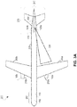
- FIG. 3A is a view of an example aircraft 200 at rest (i.e., not under maneuvering load) from the top.
- the aircraft 200 comprises, among other things, a cockpit section 250 (i.e., toward the front of the aircraft) that is connected to a fuselage 225 which is connected to an empennage 270 at the aft.
- Also connected to the empennage are left and right wings 260a, 260b under which left and right engine nacelles 210a and 210b are mounted, respectively.
- the empennage 270 includes a horizontal stabilizer 240 and a vertical stabilizer 230.
- Other aircraft (not shown) consistent with examples of the present disclosure include aircraft with fewer or additional engine nacelles 210 and/or an empennage 270 with stabilizers 230, 240 in a different configuration (e.g., cruciform; T-tail).
- the processing circuitry 110 of the external fire detection system 130 and the operator terminal 150 are housed in the cockpit section 250.
- Each nacelle 210a, 210b houses its own internal fire detection system 180a, 180b, respectively.
- a camera 175 of a ground maneuvering camera system 170 is mounted at the front of the vertical stabilizer 230.
- optical circuitry 120a and 120b are mounted on the left and right sides of the vertical stabilizer, respectively.
- Each of the optical circuitry 120a, 120b is aft of the engine nacelles 210a, 210b, they are respectively configured to optically monitor.
- Other examples may mount one or more components of the network environment 100 at other locations of the aircraft, as will be further discussed below.
- the optical circuitry 120a on the left side of the vertical stabilizer 230 and has a field of view 220 that extends from the optical circuitry 120a towards the left wing 260a to optically monitor the exterior of the left engine nacelle 210a from the aft.
- the field of view 220 continues past the wing 260a and engine nacelle 210a in particular examples. That is, the effective range of the field of view 220 may vary, e.g., based on the particular sensitivity of the optical circuitry 120a. Notwithstanding, the field of view 220 extends far enough to view the exterior of the engine nacelle 210a.
- the right engine nacelle 210b in this example is optically monitored by optical circuitry 120b, which has a different field of view (not shown) that extends from the optical circuitry 120b towards the right wing 260b to optically monitor the exterior of the right engine nacelle 210b from the aft.
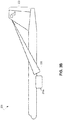
- Figure 3B is an illustration of the example aircraft 200 at rest from the left side.
- the optical circuitry 120a is mounted on the vertical stabilizer 230 aft of the engine nacelle 210a and is configured to optically monitor the exterior of the engine nacelle for a hydrocarbon fire.
- the optical circuitry 120a has a field of view 220 that includes the exterior of the engine nacelle 210a.
- the alignment of particular surfaces of the aircraft may be different under different conditions.
- maneuvering the aircraft places a load on various surfaces that causes them deflect relative to each other and/or relative to their non-loaded positions.
- Acrobatic maneuvers or maneuvers during turbulent conditions in particular can place significant stress on aircraft surfaces, causing them to deform and/or vibrate.
- the engine nacelle 210a remains within the field of view 220 of the optical circuitry 120a despite such deflection.
- the field of view 220 comprises a perimeter 295 that is substantially defined by a maximum expected deflection of the engine nacelle 210a relative to the optical circuitry 120a under maneuvering load of the aircraft 200 such that the exterior of the engine nacelle 210a remains within the field of view 220 during the maneuvering load.
- This maximum expected deflection may, for example, be based on one or more load tolerances that the aircraft 200 is designed and/or observed to withstand (e.g., as verified and/or demonstrated through mechanical stress testing).
- the maximum expected deflection is an estimated maximum distance by which the surfaces to which the optical circuitry 120a and engine nacelle 210a are mounted are able to shift relative to each other before the aircraft 200 is structurally compromised.
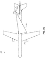
- Figure 3C illustrates an example top-view of the aircraft 200 under a maximum expected deflection of the engine nacelle 210a relative to the optical circuitry 120a under a maneuvering load.
- the vertical stabilizer 230 on which the optical circuitry 120a is mounted
- the engine nacelle 210a to be deflected leftward relative to the optical circuitry 120a.
- This deflection causes the field of view 220 of the optical circuitry 120a to shift to the right as compared to the example of Figure 3A (i.e, in which the maneuvering load was not present).
- the field of view 220 continues to include the engine nacelle 210a despite the shift.
- Figure 3D illustrates an example top-view of the aircraft 200 under a maximum expected deflection of the engine nacelle 210a relative to the optical circuitry 120a under a maneuvering load in the direction opposite to that depicted in Figure 3C .
- the vertical stabilizer 230 is deflected to the left, causing the engine nacelle 210a to be deflected rightward relative to the optical circuitry 120a.
- This deflection causes the field of view 220 of the optical circuitry 120a to shift to the left as compared to the examples of Figure 3A (in which the maneuvering load was not present) and Figure 3C (in which the maneuvering load was in the opposing direction).
- the field of view 220 continues to include the engine nacelle 210a despite the shift.
- optical circuitry 120a, 120b mounted on the horizontal stabilizer 240, as illustrated in Figure 3E.
- Figure 3E is an example top-view of the aircraft 200 at rest.
- optical circuitry 120a and 120b have respective fields of view 220a, 220b by which the optical circuitry 120a, 120b optically monitor engine nacelles 210a and 210b, respectively.
- optical circuitry 120a, 120b mounted on the fuselage 225 aft of the engine nacelles 210a, 210b, as illustrated in Figure 3F.
- Figure 3F is an example top-view of the aircraft 200 at rest.
- optical circuitry 120a and 120b have respective fields of view 220a, 220b by which the optical circuitry 120a, 120b optically monitor engine nacelles 210a and 210b, respectively.
- optical circuitry 120a, 120b illustrated in Figure 3F is mounted aft of the engine nacelles 210a, 210b, in a different example, optical circuitry 120 is mounted on the fuselage 225 ahead of an engine nacelle 210 and has a field of view 220 that extends aftward.
- optical circuitry 120a and 120b that both optically monitor engine nacelle 210a and are mounted on the left vertical and horizontal stabilizers 230, 240, respectively (and similarly with other optical circuitry 120 on the right side for engine nacelle 210b).
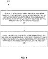
- examples of the present disclosure include a method 400, implemented in an aircraft-mounted external fire detection system 130, as illustrated in Figure 4 .
- the method 400 comprises optically monitoring an exterior of an engine nacelle 210 of an aircraft 200 for a hydrocarbon fire by detecting radiation outside of the visible light spectrum using optical circuitry 120 mounted on the aircraft 200 aft of the engine nacelle 210 (block 410).
- the method 400 further comprises using the optical circuitry 120 to determine that the fire has been continuously present for more than a threshold duration, and in response, transmitting a warning to an operator terminal 150 of the aircraft 200 (block 420).
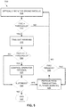
- FIG. 5 Further examples of the present disclosure include a method 500, implemented in an aircraft-mounted external fire detection system 130, as illustrated in Figure 5 .
- the external fire detection system 130 optically monitors an exterior of an engine nacelle 210 of an aircraft 200 for a hydrocarbon fire by detecting radiation outside of the visible light spectrum using optical circuitry 120a and additional optical circuitry 120b, each of which are mounted on the aircraft 200 aft of the engine nacelle 210 (block 505).
- the external fire detection system 130 determines whether a fire has been continuously present for more than a threshold duration using the optical circuitry 120a, and whether the fire has been continuously present for more than the threshold duration using the additional optical circuitry 120b (block 510).
- the external fire detection system 130 fails to determine that a fire has been continuously present for more than the threshold duration using each of the optical circuitry 120a and additional optical circuitry 120b (block 510, no)
- the external fire detection system 130 continues to optically monitor the engine nacelle 210 (block 505). If, instead, the external fire detection system 130 determines that a fire has been continuously present for more than the threshold duration using each of the optical circuitry 120a and additional optical circuitry 120b (block 510, yes), the external fire detection system 130 transmits a warning to an operator terminal 150 (e.g., so that the operator terminal 150 can activate an indicator light on an annunciator panel or otherwise present notification of the detected fire, as discussed above) (block 515).
- an operator terminal 150 e.g., so that the operator terminal 150 can activate an indicator light on an annunciator panel or otherwise present notification of the detected fire, as discussed above
- the external fire detection system 130 determines whether a threshold number of displays 160 of an operator terminal 150 are operative (block 520). If the external fire detection system 130 determines that a threshold number of displays 160 of the operator terminal 150 are operative (block 520, yes), the external fire detection system 130 controls the operator terminal 150 to display video of the engine nacelle 210 captured by a camera 175 of a ground maneuvering camera system 170 mounted on the aircraft 200 and to which the operator terminal 150 is communicatively connected (block 525). Otherwise, the external fire detection system will not control the operator terminal to display such video (block 520, no).
- the method 500 ends (block 550). If, instead, the external fire detection system 130 does receive a warning suppression signal after transmitting the warning (block 530, yes), the external fire detection system 130 refrains from transmitting further warning to the operator terminal (block 535) for at least as long as the fire remains present (block 540, yes). Once the external fire detection system 130 determines that the fire is no longer present (block 540, no), the external fire detection system 130 continues to optically monitor the engine nacelle 210 as before (block 505).
- Examples of the present disclosure further include the external fire detection system 130 implemented according to the hardware units and/or software modules illustrated in Figure 6 (e.g., as components of the processing circuitry 110, components of the optical circuitry 120, and/or instructions stored in the memory 190, as illustrated in Figure 1 ).
- the external fire detection system 130 illustrated in Figure 6 comprises a monitoring unit and/or module 710, a determining unit and/or module 720, and a transmitting unit and/or module 730.
- the monitoring unit and/or module 710 is configured to optically monitor an exterior of an engine nacelle 210 for a hydrocarbon fire by detecting radiation outside of the visible light spectrum using optical circuitry 120 mounted on an aircraft 200 aft of the engine nacelle 210.
- the determining unit and/or module 720 is configured to use the optical circuitry 120 to determine that the fire has been continuously present for more than a threshold duration.
- the transmitting unit and/or module 730 is configured to transmit a warning to an operator terminal 150 of the aircraft 200 in response to the determination made by the determining unit and/or module 720.
- Examples of the present disclosure further include various methods and processes, as described herein, implemented using various hardware configurations configured in ways that vary in certain details from the broad descriptions given above.
- one or more of the processing functionalities discussed above may be implemented using a general-purpose microprocessor configured with program instructions rather than dedicated hardware, depending on, e.g., the design and cost tradeoffs for the various approaches, and/or system-level requirements outside the scope of the present disclosure.
Landscapes
- Physics & Mathematics (AREA)
- General Physics & Mathematics (AREA)
- Spectroscopy & Molecular Physics (AREA)
- Business, Economics & Management (AREA)
- Emergency Management (AREA)
- Engineering & Computer Science (AREA)
- Multimedia (AREA)
- Aviation & Aerospace Engineering (AREA)
- Human Computer Interaction (AREA)
- Alarm Systems (AREA)
- Photometry And Measurement Of Optical Pulse Characteristics (AREA)
- Emergency Alarm Devices (AREA)
Abstract
Description
- The present disclosure generally relates to the field of fire detection systems, and more particularly to the field of aircraft-mounted external fire detection systems.
- Jet aircraft commonly house one or more engines in respective nacelles. These nacelles are commonly mounted under a wing of the aircraft. Engine fire detectors are often located within specific fire zones inside of the engine/nacelle arrangement. Such fire zones typically include the area between the engine case and the inner wall of the nacelle, around the engine fan case and/or the engine core. These detectors allow the flight crew to be alerted in the event that fire exists within that volume, i.e., external to the engine but within the nacelle compartment.
- The present disclosure relates to methods, apparatuses, systems, computer program products, software, and/or mediums for aircraft-mounted external fire detection. According to the present disclosure, an aircraft-mounted external fire detection system comprises optical circuitry mounted on an aircraft. The optical circuitry is configured to optically monitor an exterior of the engine nacelle for a hydrocarbon fire by detecting radiation outside of the visible light spectrum. The aircraft-mounted external fire detection system also comprises processing circuitry, which is communicatively coupled to the optical circuitry. The processing circuitry is configured to use the optical circuitry to determine that the fire has been continuously present for more than a threshold duration, and trigger an appropriate response (e.g., transmit a warning to an operator terminal of the aircraft). The aircraft may be capable of being manned (e.g., via the operator terminal). The aircraft may be capable of operating unmanned. The aircraft may be capable of spaceflight, may be a rotorcraft, may comprise a rocket and/or may be any other form of airborne vehicle comprising an engine-nacelle arrangement.
- According to the disclosure, a method implemented in an aircraft-mounted external fire detection system is disclosed. The method comprises optically monitoring an exterior of an engine nacelle of an aircraft for a hydrocarbon fire by detecting radiation outside of the visible light spectrum using optical circuitry mounted on the aircraft aft of the engine nacelle. The method further comprises using the optical circuitry to determine that the fire has been continuously present for more than a threshold duration, and in response, transmitting a warning to an operator terminal of the aircraft.
- The optical circuitry may have a field of view comprising a perimeter substantially defined by a maximum expected deflection of the engine nacelle relative to the optical circuitry under maneuvering load of the aircraft such that the exterior of the engine nacelle remains within the field of view during the maneuvering load.
- Transmitting the warning to the operator terminal may comprise controlling the operator terminal to display video of the engine nacelle. Controlling the operator terminal to display video of the engine nacelle may comprise triggering the operator terminal to display video captured from a ground maneuvering camera system mounted on the aircraft and to which the operator terminal is communicatively connected. In addition or in the alternative, controlling the operator terminal to display video of the engine nacelle may be responsive to determining that at least a threshold number of displays are operative at the operator terminal.
- Transmitting the warning to the operator terminal may comprise controlling the operator terminal to display a notification that is distinct from a further notification produced by a different fire detection system that monitors for fire inside of the engine nacelle.
- The method may further comprise receiving a warning suppression signal from the operator terminal, and in response, refraining from sending a further warning to the operator terminal until determining that the fire is no longer present and subsequently determining that another fire has been continuously present for more than the threshold duration.
- The method may further comprise optically monitoring the exterior of the engine nacelle for the fire by detecting radiation outside of the visible light spectrum using additional optical circuitry mounted on the aircraft aft of the engine nacelle, and refraining from transmitting the warning to the operator terminal until it is also determined that the fire has been continuously present for more than the threshold duration using the additional optical circuitry.
- The optical circuitry may be mounted on a vertical or horizontal stabilizer of the aircraft.
- According to the disclosure, an aircraft-mounted external fire detection system comprises optical circuitry mounted on an aircraft aft of an engine nacelle of the aircraft. The aircraft-mounted external fire detection system further comprises processing circuitry communicatively coupled to the optical circuitry. The optical circuitry is configured to optically monitor an exterior of the engine nacelle for a hydrocarbon fire by detecting radiation outside of the visible light spectrum. The processing circuitry is configured to use the optical circuitry to determine that the fire has been continuously present for more than a threshold duration, and in response, transmit a warning to an operator terminal of the aircraft.
- To optically monitor the exterior of the engine nacelle, the optical circuitry may have a field of view comprising a perimeter substantially defined by a maximum expected deflection of the engine nacelle relative to the optical circuitry under maneuvering load of the aircraft such that the exterior of the engine nacelle remains within the field of view during the maneuvering load.
- To transmit the warning to the operator terminal, the processing circuitry may be configured to control the operator terminal to display video of the engine nacelle. To control the operator terminal to display video of the engine nacelle, the processing circuitry may be configured to trigger the operator terminal to display video captured by a ground maneuvering camera system mounted on the aircraft to which the operator terminal is communicatively connected. In addition or in the alternative, the processing circuitry may be configured to control the operator terminal to display video of the engine nacelle responsive to determining that at least a threshold number of displays are operative at the operator terminal.
- To transmit the warning to the operator terminal, the processing circuitry may be configured to control the operator terminal to display a notification that is distinct from a further notification produced by a different fire detection system that monitors for fire inside of the engine nacelle.
- The processing circuitry may be further configured to receive a warning suppression signal from the operator terminal, and in response, refrain from sending a further warning to the operator terminal until the processing circuitry determines that the fire is no longer present and subsequently determines that another fire has been continuously present for more than the threshold duration.
- The aircraft-mounted external fire detection system may further comprise additional optical circuitry mounted on the aircraft aft of the engine nacelle. The additional optical circuitry may be configured to optically monitor the exterior of the engine nacelle for the fire by detecting radiation outside of the visible light spectrum. The processing circuitry may be further configured to refrain from transmitting the warning to the operator terminal until the processing circuitry also determines that the fire has been continuously present for more than the threshold duration using the additional optical circuitry.
- The optical circuitry may be mounted on a vertical or horizontal stabilizer of the aircraft.
- The aircraft-mounted external fire detection system may be configured to perform any of the methods described herein, e.g., via appropriate configuration of the processing circuitry.
- This disclosure further provides systems, computer program products, and/or software that correspond to one or more of the methods described herein.
- For example, according to the disclosure, a non-transitory computer readable medium storing a computer program product for controlling a programmable aircraft-mounted external fire detection system, the computer program product comprises software instructions that, when executed on processing circuitry of the programmable aircraft-mounted external fire detection system, cause the processing circuitry to: use optical circuitry, mounted on an aircraft aft of an engine nacelle of the aircraft and configured to optically monitor an exterior of the engine nacelle for a hydrocarbon fire by detecting radiation outside of the visible light spectrum, to determine that the fire has been continuously present for more than a threshold duration; and transmit a warning to an operator terminal of the aircraft in response to the determination.
- The software instructions may cause the processing circuitry to transmit the warning to the operator terminal by controlling the operator terminal to display a notification that is distinct from a further notification produced for a different fire detection system that monitors for fire inside of the engine nacelle, the notification comprising video captured by a ground maneuvering camera system mounted on the aircraft to which the operator terminal is communicatively connected.
- Also, according to the disclosure, a non-transitory computer readable medium storing a computer program product for controlling a programmable aircraft-mounted external fire detection system, the computer program product comprises software instructions that, when executed on processing circuitry of the programmable aircraft-mounted external fire detection system, cause the processing circuitry to perform any of the methods described above.
- According to the disclosure, a computer program product for controlling a programmable aircraft-mounted external fire detection system comprises software instructions that, when executed on processing circuitry of the programmable aircraft-mounted external fire detection system, cause the processing circuitry to: use optical circuitry, mounted on an aircraft aft of an engine nacelle of the aircraft and configured to optically monitor an exterior of the engine nacelle for a hydrocarbon fire by detecting radiation outside of the visible light spectrum, to determine that the fire has been continuously present for more than a threshold duration; and transmit a warning to an operator terminal of the aircraft in response to the determination.
- According to the disclosure, a computer program product for controlling a programmable aircraft-mounted external fire detection system comprises software instructions that, when executed on processing circuitry of the programmable aircraft-mounted external fire detection system, cause the processing circuitry to perform any of the methods described above.
- Arrangements according to the present disclosure are illustrated by way of example and are not limited by the accompanying figures with like references indicating like elements. In general, the use of a reference numeral should be regarded as referring to the depicted subject matter generally, whereas discussion of a specific instance of an illustrated element will append a letter designation thereto (e.g., discussion of an optical circuitry 120, generally, as opposed to discussion of particular instances of
optical circuitry -
Figure 1 is a block diagram illustrating an example network environment, according to an arrangement of the present disclosure. -
Figure 2 is an illustration of an example frame of video captured by a aircraft-mounted camera, according to an arrangement of the present disclosure. -
Figure 3A is a top-view illustration of an example aircraft with optical circuitry mounted on a vertical stabilizer, according to an arrangement of the present disclosure. -
Figure 3B is a left-side view illustration of an example aircraft with optical circuitry mounted on a vertical stabilizer, according to an arrangement of the present disclosure. -
Figures 3C and3D are top-view illustrations of an example aircraft under different maneuvering loads, according to arrangements of the present disclosure. -
Figure 3E is a top-view illustration of an example aircraft with optical circuitry mounted on a horizontal stabilizer, according to an arrangement of the present disclosure. -
Figure 3F is a top-view illustration of an example aircraft with fuselage-mounted optical circuitry, according to an arrangement of the present disclosure. -
Figure 4 is a flow diagram illustrating an example method, according to an arrangement of the present disclosure. -
Figure 5 is a flow diagram illustrating an further example method, according to an arrangement of the present disclosure. -
Figure 6 is a block diagram of an example external fire detection system, according to an arrangement of the present disclosure. - The present disclosure is directed to methods, apparatuses, systems, computer program products, and/or software for aircraft-mounted external fire detection. Traditional aircraft engine fire detection systems do not provide any information regarding whether or not a fire is outside the nacelle wall of an engine/nacelle arrangement. Traditional aircraft engine fire detection systems also do not provide any indication of a fire originating within the engine gas path, such as a tailpipe fire. According to the present disclosure, an aircraft-mounted external fire detection system addresses one or more shortcomings of traditional aircraft engine fire detection systems by, among other things, optically monitoring an exterior of an engine nacelle.
-
Figure 1 illustrates anexample network environment 100 according to an example of the disclosure. Theexample network environment 100 comprises an externalfire detection system 130 and anoperator terminal 150 communicatively connected to each other via anetwork 105. Thenetwork 105 includes one or more physical devices and/or signaling mediums capable of exchanging communication signals between the externalfire detection system 130 and theoperator terminal 150. Examples of such anetwork 105 include (but are not limited to) one or more signaling mediums; one or more local area networks; one or more wireless networks; one or more Internet Protocol-based networks; one or more Ethernet networks; one or more optical networks; one or more ad hoc networks; and/or one or more electrical buses. Such anetwork 105 may comprise any number of networking devices such as routers, gateways, switches, hubs, firewalls, multiplexers, controllers, and the like (not shown) supporting the exchange of such communication signals. - The external
fire detection system 130 comprisesoptical circuitry 120a andprocessing circuitry 110. Theoptical circuitry 120a is configured to optically monitor for a hydrocarbon fire by detecting radiation outside of the visible light spectrum (i.e., ultraviolet and/or infrared radiation). For example, theoptical circuitry 120a may be configured to detect a particular wavelength of infrared radiation that is produced in abundance during the burning of a hydrocarbon, such as jet fuel and/or oil. Suchoptical circuitry 120a may rely on the particular radiation wavelength emitted by a given byproduct of hydrocarbon combustion. For example, hot carbon dioxide produced from the burning of a given hydrocarbon may produce significant amounts of infrared radiation at approximately 4.3 micrometers relative to the surrounding ambient air. Accordingly, theoptical circuitry 120a may be configured to trigger a signal in response to a spike in radiation at 4.3 micrometers in wavelength occurring within a particular field of view of theoptical circuitry 120a. According to other examples, theoptical circuitry 120a detects and responds to radiation at one or more other wavelengths. In a particular example, theoptical circuitry 120a is a solar-blind optical flame detector. - The
processing circuitry 110 is communicatively coupled to theoptical circuitry 120a. According to particular examples of the disclosure, theprocessing circuitry 110 comprises one or more microprocessors, microcontrollers, hardware circuits, discrete logic circuits, hardware registers, digital signal processors (DSPs), field-programmable gate arrays (FPGAs), application-specific integrated circuits (ASICs), memory, or a combination thereof. In one such example, theprocessing circuitry 110 includes programmable hardware capable of executing software instructions stored, e.g., inmemory 190 as a machine-readable computer program. Examples ofsuch memory 190 include any non-transitory machine-readable media known in the art or that may be developed, whether volatile or non-volatile, including (but not limited to) solid state media (e.g., SRAM, DRAM, DDRAM, ROM, PROM, EPROM, flash memory, solid state drive, etc.), removable storage devices (e.g., Secure Digital (SD) card, miniSD card, microSD card, memory stick, thumb-drive, USB flash drive, ROM cartridge, Universal Media Disc), fixed drive (e.g., magnetic hard disk drive), or the like, individually or in any combination. - The
processing circuitry 110 is configured to use theoptical circuitry 120a to determine whether to transmit a warning to theoperator terminal 150 via thenetwork 105. In particular, theprocessing circuitry 110 transmits a warning to theoperator terminal 150 in response to determining that the fire has been continuously present for more than a threshold duration (e.g., three seconds; five seconds). The threshold duration may be such that minor flare-ups of exhaust gas and/or ingested objects (e.g., birds) from the engine nacelle and/or fires on the ground moving quickly past the field of view of theoptical circuitry 120a are inadequate to cause theprocessing circuitry 110 to transmit the warning. - In a particular example, the threshold duration is one of a plurality of predefined durations with which the
processing circuitry 110 is configured. For example, the threshold duration may be of a smaller or larger duration (e.g., three or five seconds) based on whether theprocessing circuitry 110 is configured to a more or less sensitive fire detection mode, respectively. In a particular example, theprocessing circuitry 110 is configurable through an appropriate control signal sent from theoperator terminal 150. - According to particular examples, the determination that the fire has been continuously present is based on a steady or periodic signal received from the
optical circuitry 120a. Other examples determine that the fire has been continuously present based on a different use of theoptical circuitry 120a. - In a further example, the external
fire detection system 130 comprises additionaloptical circuitry 120b. In an example, the additionaloptical circuitry 120b is also configured to optically monitor the exterior of an engine nacelle for a hydrocarbon fire by detecting radiation outside of the visible light spectrum. As will be further explained below, in some examples the engine nacelle monitored byoptical circuitry 120b is same as that which is monitored byoptical circuitry 120a, and in other examples, the engine nacelle monitored byoptical circuitry 120b is different. For example, according to an example in whichoptical circuitry 120a andoptical circuitry 120b monitor the same engine nacelle, the processing circuitry is further configured to refrain from transmitting the warning to theoperator terminal 150 until theprocessing circuitry 110 not only determines that the fire has been continuously present for more than the threshold duration using theoptical circuitry 120a, but also determines that the fire has been continuously present for more than the threshold duration using the additionaloptical circuitry 120b. According to such an example, the use ofoptical circuitry 120a andoptical circuitry 120b to monitor the same engine nacelle may improve the detection of the hydrocarbon fire and/or reduce false positive fire detection results, e.g., by optically monitoring the same engine nacelle from different positions. In particular example, at least one of these positions is an aft-mounted position. Accordingly, various examples of the present disclosure include externalfire detection systems 130 that optically monitor each of one, some, or all of the engine nacelles on the aircraft from any number of viewpoints, each being mounted with corresponding optical circuitry 120. - In an example, the warning transmitted by the
processing circuitry 110 controls theoperator terminal 150 to display a notification of the fire, e.g., in a manner conspicuous to an operator of the aircraft, such as a pilot or other aircrew member, on adisplay 160a of theoperator terminal 150. Examples of adisplay 160a according to various examples herein include a telltale, an annunciator panel, a multi-function display (MFD), a touchscreen display, a Liquid Crystal Display (LCD), and/or a Light Emitting Diode (LED) display. In a particular example, theprocessing circuitry 110 controls theoperator terminal 150 to display an engine-indicating and crew-alerting system (EICAS) warning and/or a Master Warning indication on such adisplay 160a. In some examples of the present disclosure, theoperator terminal 150 further includesinput circuitry 195 for accepting input from an operator (e.g., a pilot). According to particular examples, theinput circuitry 195 includes one or more of: a pointing device (e.g., a mouse, stylus, touchpad, trackball, pointing stick, joystick), a microphone (e.g., for speech input), an optical sensor (e.g., for optical recognition of gestures), and/or pushkeys (e.g., a keyboard, number-pad, and/or function keys). According to particular examples of the present disclosure, theinterface circuitry 195 is implemented as a unitary physical component, or as a plurality of physical components that are contiguously or separately arranged, any of which may be communicatively coupled to any other, or may communicate with any other via an appropriate signaling medium (e.g., network 105). - In a particular example, the
network environment 100 further comprises an internalfire detection system 180 that is communicatively connected to thenetwork 105 and is distinct from the externalfire detection system 130. The internalfire detection system 180 monitors for fire inside of the engine nacelle. According to such an example, the notification displayed by theoperator terminal 150 responsive to the warning from the externalfire detection system 130 may be distinct from a further notification produced for the internalfire detection system 180. In a particular example, the notification displayed by theoperator terminal 150 responsive to the warning is distinct from a flight deck fire switch and fuel cutoff lever corresponding to the engine nacelle experiencing the external fire. Such an example may, e.g., enable an operator to distinguish between external and internal nacelle fires (e.g., between a fire in the exhaust gas path and a fire in the engine core), such that the operator may make a correspondingly appropriate response. For example, an internal engine fire may be addressed by cutting fuel to the engine and activating a fire suppression system (not shown), whereas an external fire may be addressed by merely reducing engine throttle and/or changing the fuel mixture to reduce the amount of flammable exhaust being produced from the engine nacelle. - According to particular examples of the present disclosure, the
network environment 100 includes acamera 175, and the warning transmitted by theprocessing circuitry 110 controls theoperator terminal 150 to display video of the engine nacelle captured by thecamera 175. Thecamera 175 is an optical device that treats radiation emitted by the hydrocarbon fire in a manner that is consistent with radiation not emitted by the hydrocarbon fire (i.e., in contrast to the optical circuitry 120). Accordingly, an operator may be afforded with a view of the engine nacelle in response to the externalfire detection system 130 detecting the hydrocarbon fire. The ability to view video of the engine nacelle may enable an operator of the aircraft to determine the severity of the fire and determine whether the warning produced by the externalfire detection system 130 is a false positive fire detection result, and/or determine whether to land, turnback, and/or evacuate the aircraft. - In an example of the present disclosure, a ground maneuvering
camera system 170 is comprised in thenetwork environment 100, and thecamera 175 is comprised in the ground maneuveringcamera system 170. A ground maneuveringcamera system 170 is a camera system that includes at least onecamera 175 and is commonly used to give an operator of the aircraft a real-time view of areas in proximity to the aircraft (e.g., the landing gear, engine nacelles, and the ground underneath) for use in taxing. According to an example, to control theoperator terminal 150 to display video of the engine nacelle, theprocessing circuitry 110 is configured to trigger theoperator terminal 150 to display video captured by the ground maneuveringcamera system 170 mounted on the aircraft and to which theoperator terminal 150 is communicatively connected, i.e., vianetwork 105. - In a particular example of the present disclosure, the
operator terminal 150 comprises a plurality of displays, e.g.,display 160a and display 160b. In a further example, theprocessing circuitry 110 is configured to control theoperator terminal 150 to display video of the engine nacelle responsive to determining that at least a threshold number ofdisplays 160a, 160b are operative at theoperator terminal 150. For example, in response to theprocessing circuitry 110 determining thatonly display 160a is operative (e.g., due to display 160b being inoperative), theprocessing circuitry 110 may refrain from controlling theoperator terminal 150 to display video captured bycamera 175. Such an example may prevent one of the few (or the only) display 160 in operation atoperator terminal 150 from being commandeered by the external fire detection system 130 (which may be in use for displaying other critical information to the pilot, for example). - In a further example, the
processing circuitry 110 is further configured to receive a warning suppression signal from theoperator terminal 150, and in response, refrain from sending a further warning to theoperator terminal 150 until theprocessing circuitry 110 determines that the fire is no longer present and subsequently determines that another fire has been continuously present for more than the threshold duration. For example, the warning suppression signal may be triggered via theoperator terminal 150 by an operator of the aircraft who has determined that the fire warning is the result of a false positive and wishes to prevent being further distracted by a corresponding notification on thedisplay 160a. -
Figure 2 illustrates an example frame of video captured from the perspective of acamera 175 of a ground maneuveringcamera system 170 mounted aft of anengine nacelle 210, according to an example of the present disclosure. Thecamera 175 captures video within a field ofview 290 that includes thatengine nacelle 210. Theoptical circuitry 120a is configured with a field ofview 220 with which to optically monitor theengine nacelle 210. As shown inFigure 2 , the field ofview 220 of theoptical circuitry 120a is narrower than the field ofview 290 of thecamera 175, yet large enough to include outboard and inboard sides of the engine nacelle 210 (i.e., no portion of theengine nacelle 210 is outside of the perimeter of the field ofview 220. In one example, theoptical circuitry 120a is mounted to the aircraft at a location that is substantially coaxial to thecamera 175, such that the perspective of theoptical circuitry 120a is substantially as shown inFigure 2 . As will be discussed further below, other examples include theoptical circuitry 120a being mounted at different locations, e.g., such that the field ofview 220 similarly extends to a relatively narrow area surrounding the engine nacelle in a manner similar to that illustrated inFigure 2 , albeit from a different perspective. - According to a particular example, the relatively narrow field of
view 220 around the exterior of theengine nacelle 210 helps to reduce false positive fire detection results by excluding areas where theengine nacelle 210 is unlikely to produce a hydrocarbon fire (e.g., areas outside of the exhaust gas path of the engine nacelle 210). As described above, in an example,processing circuitry 110 of the externalfire detection system 130 transmits a warning that controls anoperator terminal 150 to display video (such as that illustrated inFigure 2 ) responsive to detecting a hydrocarbon fire exterior to theengine nacelle 210. - According to various examples, elements of the
network environment 100 are mounted and/or housed at various locations of theaircraft 200 as illustrated in the example ofFigure 3A. Figure 3A is a view of anexample aircraft 200 at rest (i.e., not under maneuvering load) from the top. Theaircraft 200 comprises, among other things, a cockpit section 250 (i.e., toward the front of the aircraft) that is connected to afuselage 225 which is connected to anempennage 270 at the aft. Also connected to the empennage are left andright wings right engine nacelles empennage 270 includes ahorizontal stabilizer 240 and avertical stabilizer 230. Other aircraft (not shown) consistent with examples of the present disclosure include aircraft with fewer oradditional engine nacelles 210 and/or anempennage 270 withstabilizers - According to this example, the
processing circuitry 110 of the externalfire detection system 130 and theoperator terminal 150 are housed in thecockpit section 250. Eachnacelle fire detection system camera 175 of a ground maneuveringcamera system 170 is mounted at the front of thevertical stabilizer 230. Further still,optical circuitry optical circuitry engine nacelles network environment 100 at other locations of the aircraft, as will be further discussed below. - As shown in the example of
Figure 3A , theoptical circuitry 120a on the left side of thevertical stabilizer 230 and has a field ofview 220 that extends from theoptical circuitry 120a towards theleft wing 260a to optically monitor the exterior of theleft engine nacelle 210a from the aft. Although not illustrated for the sake of clarity, the field ofview 220 continues past thewing 260a andengine nacelle 210a in particular examples. That is, the effective range of the field ofview 220 may vary, e.g., based on the particular sensitivity of theoptical circuitry 120a. Notwithstanding, the field ofview 220 extends far enough to view the exterior of theengine nacelle 210a. - Correspondingly, the
right engine nacelle 210b in this example is optically monitored byoptical circuitry 120b, which has a different field of view (not shown) that extends from theoptical circuitry 120b towards theright wing 260b to optically monitor the exterior of theright engine nacelle 210b from the aft. -
Figure 3B is an illustration of theexample aircraft 200 at rest from the left side. As shown, theoptical circuitry 120a is mounted on thevertical stabilizer 230 aft of theengine nacelle 210a and is configured to optically monitor the exterior of the engine nacelle for a hydrocarbon fire. In particular, theoptical circuitry 120a has a field ofview 220 that includes the exterior of theengine nacelle 210a. - The alignment of particular surfaces of the aircraft may be different under different conditions. In particular, maneuvering the aircraft places a load on various surfaces that causes them deflect relative to each other and/or relative to their non-loaded positions. Acrobatic maneuvers or maneuvers during turbulent conditions in particular can place significant stress on aircraft surfaces, causing them to deform and/or vibrate. According to a further example of the present disclosure, the
engine nacelle 210a remains within the field ofview 220 of theoptical circuitry 120a despite such deflection. In particular, the field ofview 220 comprises a perimeter 295 that is substantially defined by a maximum expected deflection of theengine nacelle 210a relative to theoptical circuitry 120a under maneuvering load of theaircraft 200 such that the exterior of theengine nacelle 210a remains within the field ofview 220 during the maneuvering load. This maximum expected deflection may, for example, be based on one or more load tolerances that theaircraft 200 is designed and/or observed to withstand (e.g., as verified and/or demonstrated through mechanical stress testing). According to a particular example, the maximum expected deflection is an estimated maximum distance by which the surfaces to which theoptical circuitry 120a andengine nacelle 210a are mounted are able to shift relative to each other before theaircraft 200 is structurally compromised. -
Figure 3C illustrates an example top-view of theaircraft 200 under a maximum expected deflection of theengine nacelle 210a relative to theoptical circuitry 120a under a maneuvering load. In particular, in this example, the vertical stabilizer 230 (on which theoptical circuitry 120a is mounted) is deflected to the right, causing theengine nacelle 210a to be deflected leftward relative to theoptical circuitry 120a. This deflection causes the field ofview 220 of theoptical circuitry 120a to shift to the right as compared to the example ofFigure 3A (i.e, in which the maneuvering load was not present). As shown, the field ofview 220 continues to include theengine nacelle 210a despite the shift. -
Figure 3D illustrates an example top-view of theaircraft 200 under a maximum expected deflection of theengine nacelle 210a relative to theoptical circuitry 120a under a maneuvering load in the direction opposite to that depicted inFigure 3C . In particular, thevertical stabilizer 230 is deflected to the left, causing theengine nacelle 210a to be deflected rightward relative to theoptical circuitry 120a. This deflection causes the field ofview 220 of theoptical circuitry 120a to shift to the left as compared to the examples ofFigure 3A (in which the maneuvering load was not present) andFigure 3C (in which the maneuvering load was in the opposing direction). As shown, the field ofview 220 continues to include theengine nacelle 210a despite the shift. - Other examples of the present disclosure include the
optical circuitry horizontal stabilizer 240, as illustrated inFigure 3E. Figure 3E is an example top-view of theaircraft 200 at rest. As shown in the example ofFigure 3E ,optical circuitry view optical circuitry engine nacelles - Yet other examples of the present disclosure include the
optical circuitry fuselage 225 aft of theengine nacelles Figure 3F. Figure 3F is an example top-view of theaircraft 200 at rest. As shown in the example ofFigure 3F ,optical circuitry view optical circuitry engine nacelles optical circuitry Figure 3F is mounted aft of theengine nacelles fuselage 225 ahead of anengine nacelle 210 and has a field ofview 220 that extends aftward. - Other examples include any combination of the above. For example,
optical circuitry engine nacelle 210a and are mounted on the left vertical andhorizontal stabilizers engine nacelle 210b). - In view of the above, examples of the present disclosure include a
method 400, implemented in an aircraft-mounted externalfire detection system 130, as illustrated inFigure 4 . Themethod 400 comprises optically monitoring an exterior of anengine nacelle 210 of anaircraft 200 for a hydrocarbon fire by detecting radiation outside of the visible light spectrum using optical circuitry 120 mounted on theaircraft 200 aft of the engine nacelle 210 (block 410). Themethod 400 further comprises using the optical circuitry 120 to determine that the fire has been continuously present for more than a threshold duration, and in response, transmitting a warning to anoperator terminal 150 of the aircraft 200 (block 420). - Further examples of the present disclosure include a
method 500, implemented in an aircraft-mounted externalfire detection system 130, as illustrated inFigure 5 . According to themethod 500, the externalfire detection system 130 optically monitors an exterior of anengine nacelle 210 of anaircraft 200 for a hydrocarbon fire by detecting radiation outside of the visible light spectrum usingoptical circuitry 120a and additionaloptical circuitry 120b, each of which are mounted on theaircraft 200 aft of the engine nacelle 210 (block 505). The externalfire detection system 130 determines whether a fire has been continuously present for more than a threshold duration using theoptical circuitry 120a, and whether the fire has been continuously present for more than the threshold duration using the additionaloptical circuitry 120b (block 510). - If the external
fire detection system 130 fails to determine that a fire has been continuously present for more than the threshold duration using each of theoptical circuitry 120a and additionaloptical circuitry 120b (block 510, no), the externalfire detection system 130 continues to optically monitor the engine nacelle 210 (block 505). If, instead, the externalfire detection system 130 determines that a fire has been continuously present for more than the threshold duration using each of theoptical circuitry 120a and additionaloptical circuitry 120b (block 510, yes), the externalfire detection system 130 transmits a warning to an operator terminal 150 (e.g., so that theoperator terminal 150 can activate an indicator light on an annunciator panel or otherwise present notification of the detected fire, as discussed above) (block 515). - According to the
method 500, the externalfire detection system 130 then determines whether a threshold number of displays 160 of anoperator terminal 150 are operative (block 520). If the externalfire detection system 130 determines that a threshold number of displays 160 of theoperator terminal 150 are operative (block 520, yes), the externalfire detection system 130 controls theoperator terminal 150 to display video of theengine nacelle 210 captured by acamera 175 of a ground maneuveringcamera system 170 mounted on theaircraft 200 and to which theoperator terminal 150 is communicatively connected (block 525). Otherwise, the external fire detection system will not control the operator terminal to display such video (block 520, no). - Provided that the external
fire detection system 130 does not receive a warning suppression signal after transmitting the warning (block 530, no), themethod 500 ends (block 550). If, instead, the externalfire detection system 130 does receive a warning suppression signal after transmitting the warning (block 530, yes), the externalfire detection system 130 refrains from transmitting further warning to the operator terminal (block 535) for at least as long as the fire remains present (block 540, yes). Once the externalfire detection system 130 determines that the fire is no longer present (block 540, no), the externalfire detection system 130 continues to optically monitor theengine nacelle 210 as before (block 505). - Examples of the present disclosure further include the external
fire detection system 130 implemented according to the hardware units and/or software modules illustrated inFigure 6 (e.g., as components of theprocessing circuitry 110, components of the optical circuitry 120, and/or instructions stored in thememory 190, as illustrated inFigure 1 ). The externalfire detection system 130 illustrated inFigure 6 comprises a monitoring unit and/ormodule 710, a determining unit and/ormodule 720, and a transmitting unit and/ormodule 730. The monitoring unit and/ormodule 710 is configured to optically monitor an exterior of anengine nacelle 210 for a hydrocarbon fire by detecting radiation outside of the visible light spectrum using optical circuitry 120 mounted on anaircraft 200 aft of theengine nacelle 210. The determining unit and/ormodule 720 is configured to use the optical circuitry 120 to determine that the fire has been continuously present for more than a threshold duration. The transmitting unit and/ormodule 730 is configured to transmit a warning to anoperator terminal 150 of theaircraft 200 in response to the determination made by the determining unit and/ormodule 720. - Examples of the present disclosure further include various methods and processes, as described herein, implemented using various hardware configurations configured in ways that vary in certain details from the broad descriptions given above. For instance, one or more of the processing functionalities discussed above may be implemented using a general-purpose microprocessor configured with program instructions rather than dedicated hardware, depending on, e.g., the design and cost tradeoffs for the various approaches, and/or system-level requirements outside the scope of the present disclosure.
- Indeed, examples of the present disclosure are, of course, carried out in other ways than those specifically set forth herein without departing from the essential characteristics therefrom. The examples disclosed herein are to be considered in all respects as illustrative and not restrictive, and all changes coming within the meaning and equivalency range of the appended claims are intended to be embraced therein. In particular, although steps of particular processes or methods described herein are shown and described as being in a particular sequence or temporal order, the steps of any such processes or methods are not limited to being carried out in any particular sequence or order, absent an indication otherwise. Indeed, the steps in such processes or methods are generally carried out in various different sequences and orders according to particular examples of the present disclosure while still falling within the scope of the present disclosure.
Claims (15)
- An aircraft-mounted external fire detection system (130) comprising:optical circuitry (120a) mounted on an aircraft (200) aft of an engine nacelle (210) of the aircraft (200), the optical circuitry (120a) being configured to optically monitor an exterior of the engine nacelle (210) for a hydrocarbon fire by detecting radiation outside of the visible light spectrum ;processing circuitry (110) communicatively coupled to the optical circuitry (120a) and configured to use the optical circuitry (120a) to determine that the fire has been continuously present for more than a threshold duration, and in response, transmit a warning to an operator terminal (150) of the aircraft (200).
- The aircraft-mounted external fire detection system (130) of claim 1, wherein to optically monitor the exterior of the engine nacelle (210), the optical circuitry (120a) has a field of view (220) comprising a perimeter substantially defined by a maximum expected deflection of the engine nacelle (210) relative to the optical circuitry (120a) under maneuvering load of the aircraft (200) such that the exterior of the engine nacelle (210) remains within the field of view (220) during the maneuvering load.
- The aircraft-mounted external fire detection system (130) of claim 1 or 2, wherein to transmit the warning to the operator terminal (150), the processing circuitry (110) is configured to control the operator terminal (150) to display video of the engine nacelle (210).
- The aircraft-mounted external fire detection system (130) of claim 3, wherein to control the operator terminal (150) to display video of the engine nacelle (210), the processing circuitry (110) is configured to trigger the operator terminal (150) to display video captured by a ground maneuvering camera system (170) mounted on the aircraft (200) and to which the operator terminal (150) is communicatively connected.
- The aircraft-mounted external fire detection system (130) of claim 3 or 4, wherein the processing circuitry (110) is configured to control the operator terminal (150) to display video of the engine nacelle (210) responsive to determining that at least a threshold number of displays (160) are operative at the operator terminal (150).
- The aircraft-mounted external fire detection system (130) of any preceding claim, wherein to transmit the warning to the operator terminal (150), the processing circuitry (110) is configured to control the operator terminal (150) to display a notification that is distinct from a further notification produced for a different fire detection system (180) that monitors for fire inside of the engine nacelle (210).
- The aircraft-mounted external fire detection system (130) of any preceding claim, wherein the processing circuitry (110) is further configured to receive a warning suppression signal from the operator terminal (150), and in response, refrain from sending a further warning to the operator terminal (150) until the processing circuitry (110) determines that the fire is no longer present and subsequently determines that another fire has been continuously present for more than the threshold duration.
- The aircraft-mounted external fire detection system (130) of any preceding claim:further comprising additional optical circuitry (120b) mounted on the aircraft (200) aft of the engine nacelle (210), the additional optical circuitry (120b) being configured to optically monitor the exterior of the engine nacelle (210) for the fire by detecting radiation outside of the visible light spectrum;wherein the processing circuitry (110) is further configured to refrain from transmitting the warning to the operator terminal (150) until the processing circuitry (110) also determines that the fire has been continuously present for more than the threshold duration using the additional optical circuitry (120b).
- The aircraft-mounted external fire detection system (130) of any preceding claim, wherein the optical circuitry (120a) is mounted on a vertical or horizontal stabilizer (230, 240) of the aircraft (200).
- A method (400,500), implemented in an aircraft-mounted external fire detection system (130), the method comprising:optically monitoring (410) an exterior of an engine nacelle (210) of an aircraft (200) for a hydrocarbon fire by detecting radiation outside of the visible light spectrum using optical circuitry (120a) mounted on the aircraft (200) aft of the engine nacelle (210);using (420) the optical circuitry (120a) to determine that the fire has been continuously present for more than a threshold duration, and in response, transmitting a warning to an operator terminal (150) of the aircraft (200).
- The method of claim 10, wherein transmitting the warning to the operator terminal (150) comprises controlling the operator terminal (150) to display video of the engine nacelle (210).
- The method of claim 11, wherein controlling the operator terminal (150) to display video of the engine nacelle (210):comprises triggering the operator terminal (150) to display video captured from a ground maneuvering camera system (170) mounted on the aircraft (200) and to which the operator terminal (150) is communicatively connected; and/oris responsive to determining that at least a threshold number of displays (160) are operative at the operator terminal (150).
- The method of any of claims 10 to 12, wherein transmitting the warning to the operator terminal (150) comprises controlling the operator terminal (150) to display a notification that is distinct from a further notification produced for a different fire detection system (180) that monitors for fire inside of the engine nacelle (210).
- The method of any of claims 10 to 13, further comprising receiving a warning suppression signal from the operator terminal (150), and in response, refraining from sending a further warning to the operator terminal (150) until determining that the fire is no longer present and subsequently determining that another fire has been continuously present for more than the threshold duration.
- The method of any of claims 10 to 14, further comprising:optically monitoring the exterior of the engine nacelle (210) for the fire by detecting radiation outside of the visible light spectrum using additional optical circuitry (120b) mounted on the aircraft (200) aft of the engine nacelle (210);refraining from transmitting the warning to the operator terminal (150) until it is also determined that the fire has been continuously present for more than the threshold duration using the additional optical circuitry (120b).
Applications Claiming Priority (1)
| Application Number | Priority Date | Filing Date | Title |
|---|---|---|---|
| US15/641,975 US9976907B1 (en) | 2017-07-05 | 2017-07-05 | Airplane-mounted external fire detection system |
Publications (2)
| Publication Number | Publication Date |
|---|---|
| EP3425603A1 true EP3425603A1 (en) | 2019-01-09 |
| EP3425603B1 EP3425603B1 (en) | 2023-10-04 |
Family
ID=62122149
Family Applications (1)
| Application Number | Title | Priority Date | Filing Date |
|---|---|---|---|
| EP18181607.5A Active EP3425603B1 (en) | 2017-07-05 | 2018-07-04 | Aircraft-mounted external fire detection system |
Country Status (3)
| Country | Link |
|---|---|
| US (2) | US9976907B1 (en) |
| EP (1) | EP3425603B1 (en) |
| CN (1) | CN109215272A (en) |
Families Citing this family (5)
| Publication number | Priority date | Publication date | Assignee | Title |
|---|---|---|---|---|
| FR3068392A1 (en) * | 2017-06-29 | 2019-01-04 | Airbus Operations (S.A.S.) | DEVICE FOR MONITORING A TURBOMACHINE OF AN AIRCRAFT |
| US9976907B1 (en) * | 2017-07-05 | 2018-05-22 | The Boeing Company | Airplane-mounted external fire detection system |
| WO2022100891A1 (en) * | 2020-11-10 | 2022-05-19 | Airbus Operations (S.A.S.) | Aircraft comprising a system for detecting a fire in a turbomachine |
| JP7444127B2 (en) * | 2021-04-08 | 2024-03-06 | 株式会社デンソー | aircraft surveillance system |
| US12109445B2 (en) | 2022-06-14 | 2024-10-08 | The Boeing Company | Fire extinguishing system and method |
Citations (3)
| Publication number | Priority date | Publication date | Assignee | Title |
|---|---|---|---|---|
| US5534697A (en) * | 1994-09-02 | 1996-07-09 | Rockwell International Corporation | Electro-optical sensor system for use in observing objects |
| DE102007002493A1 (en) * | 2007-01-17 | 2008-08-21 | Franz Butschek | Airplane control camera system has rotary cameras designed in aerodynamic manner and are responsible for nose landing gear or main landing gear and contain heated protective glass housing |
| WO2012131105A1 (en) * | 2011-04-01 | 2012-10-04 | Latecoere | Aircraft provided with a system for observing part of the aircraft's environment |
Family Cites Families (10)
| Publication number | Priority date | Publication date | Assignee | Title |
|---|---|---|---|---|
| US5051590A (en) * | 1989-12-06 | 1991-09-24 | Santa Barbara Research Center | Fiber optic flame detection and temperature measurement system having one or more in-line temperature dependent optical filters |
| US6408259B1 (en) * | 2000-02-01 | 2002-06-18 | General Electric Company | Alert generation for trend performance analysis |
| US7505604B2 (en) * | 2002-05-20 | 2009-03-17 | Simmonds Precision Prodcuts, Inc. | Method for detection and recognition of fog presence within an aircraft compartment using video images |
| US7487029B2 (en) * | 2004-05-21 | 2009-02-03 | Pratt & Whitney Canada | Method of monitoring gas turbine engine operation |
| US9127597B2 (en) * | 2011-09-23 | 2015-09-08 | The Boeing Company | Sensor system |
| GB2511809B (en) * | 2013-03-14 | 2015-12-23 | Kidde Tech Inc | Thermal event detection and notification system |
| CN106205012B (en) * | 2015-05-04 | 2018-07-06 | 中国航空工业集团公司西安飞机设计研究所 | A kind of three bellows pneumatic type fire -detecting systems alarm logic design method |
| CN105118220B (en) * | 2015-09-17 | 2017-09-22 | 杨珊珊 | A kind of unmanned vehicle temperature pre-warning system and method |
| CN106226239A (en) * | 2016-10-14 | 2016-12-14 | 深圳全景威视科技有限公司 | Big angle of visual field intelligent image type fire detector and Intelligent Fire Detection method thereof |
| US9976907B1 (en) * | 2017-07-05 | 2018-05-22 | The Boeing Company | Airplane-mounted external fire detection system |
-
2017
- 2017-07-05 US US15/641,975 patent/US9976907B1/en not_active Expired - Fee Related
-
2018
- 2018-05-18 US US15/983,148 patent/US10371575B2/en active Active
- 2018-06-22 CN CN201810650263.5A patent/CN109215272A/en active Pending
- 2018-07-04 EP EP18181607.5A patent/EP3425603B1/en active Active
Patent Citations (3)
| Publication number | Priority date | Publication date | Assignee | Title |
|---|---|---|---|---|
| US5534697A (en) * | 1994-09-02 | 1996-07-09 | Rockwell International Corporation | Electro-optical sensor system for use in observing objects |
| DE102007002493A1 (en) * | 2007-01-17 | 2008-08-21 | Franz Butschek | Airplane control camera system has rotary cameras designed in aerodynamic manner and are responsible for nose landing gear or main landing gear and contain heated protective glass housing |
| WO2012131105A1 (en) * | 2011-04-01 | 2012-10-04 | Latecoere | Aircraft provided with a system for observing part of the aircraft's environment |
Non-Patent Citations (1)
| Title |
|---|
| P HASCHBERGER ET AL: "Spectrometric infiight measurement of aircraft exhaust emissions' First results of the June 1995 campaign", JOURNAL OF GEOPHYSICAL RESEARCH, 20 November 1996 (1996-11-20), pages 25996 - 26006, XP055049209, Retrieved from the Internet <URL:http://onlinelibrary.wiley.com/store/10.1029/96JD02216/asset/jgrd4493.pdf?v=1&t=hbs0kvjv&s=4063fdb211469c5b5c8cbc8424c98cb1860b3b16> [retrieved on 20130110] * |
Also Published As
| Publication number | Publication date |
|---|---|
| CN109215272A (en) | 2019-01-15 |
| EP3425603B1 (en) | 2023-10-04 |
| US10371575B2 (en) | 2019-08-06 |
| US9976907B1 (en) | 2018-05-22 |
| US20190011314A1 (en) | 2019-01-10 |
Similar Documents
| Publication | Publication Date | Title |
|---|---|---|
| US10371575B2 (en) | Airplane-mounted external fire detection system | |
| JP6419293B2 (en) | Supercooled large droplet icing condition detection system using laser | |
| US8200379B2 (en) | Smart recovery system | |
| US9472079B2 (en) | Method and system to enable selective smoke detection sensitivity | |
| US10198956B2 (en) | Unmanned aerial vehicle collision avoidance system | |
| US9108739B2 (en) | Taxiing aircraft vicinity visualization system and method | |
| JP6377315B2 (en) | Icing condition detection system for supercooled large droplets | |
| US20250346361A1 (en) | System and Method for Monitoring and Reducing an Aircraft Emission Level | |
| CN105092047B (en) | Overheat sensor system | |
| US10748432B2 (en) | Piloting assistance system of a platform, and associated method | |
| EP3147000B1 (en) | Automated galley fire protection system | |
| EP3399509A1 (en) | Airplane fire detection system | |
| US20190156687A1 (en) | Unmanned aerial vehicle collision avoidance system | |
| US20260077877A1 (en) | Airplane fuel contaminant detection system | |
| EP3396318B1 (en) | A system for detecting the presence of emission vapors for aircraft using a composite visual image | |
| EP3614226B1 (en) | Enhanced pitot tube power management system and method | |
| CN108303991A (en) | Unmanned plane obstruction warning system | |
| US20190236922A1 (en) | Optical Cabin and Cargo Smoke Detection Using Multiple Spectrum Light | |
| US20100170982A1 (en) | Aircraft without pilot (for commercial and military use) | |
| KR102859567B1 (en) | Electric airplane fire monitoring system | |
| Pearson et al. | Design of sense-and-avoid standards for RQ-7B Shadow under loss-link |
Legal Events
| Date | Code | Title | Description |
|---|---|---|---|
| PUAI | Public reference made under article 153(3) epc to a published international application that has entered the european phase |
Free format text: ORIGINAL CODE: 0009012 |
|
| STAA | Information on the status of an ep patent application or granted ep patent |
Free format text: STATUS: REQUEST FOR EXAMINATION WAS MADE |
|
| 17P | Request for examination filed |
Effective date: 20180704 |
|
| AK | Designated contracting states |
Kind code of ref document: A1 Designated state(s): AL AT BE BG CH CY CZ DE DK EE ES FI FR GB GR HR HU IE IS IT LI LT LU LV MC MK MT NL NO PL PT RO RS SE SI SK SM TR |
|
| AX | Request for extension of the european patent |
Extension state: BA ME |
|
| TPAC | Observations filed by third parties |
Free format text: ORIGINAL CODE: EPIDOSNTIPA |
|
| STAA | Information on the status of an ep patent application or granted ep patent |
Free format text: STATUS: EXAMINATION IS IN PROGRESS |
|
| 17Q | First examination report despatched |
Effective date: 20210701 |
|
| RAP3 | Party data changed (applicant data changed or rights of an application transferred) |
Owner name: THE BOEING COMPANY |
|
| GRAP | Despatch of communication of intention to grant a patent |
Free format text: ORIGINAL CODE: EPIDOSNIGR1 |
|
| STAA | Information on the status of an ep patent application or granted ep patent |
Free format text: STATUS: GRANT OF PATENT IS INTENDED |
|
| INTG | Intention to grant announced |
Effective date: 20230426 |
|
| P01 | Opt-out of the competence of the unified patent court (upc) registered |
Effective date: 20230612 |
|
| GRAS | Grant fee paid |
Free format text: ORIGINAL CODE: EPIDOSNIGR3 |
|
| GRAA | (expected) grant |
Free format text: ORIGINAL CODE: 0009210 |
|
| STAA | Information on the status of an ep patent application or granted ep patent |
Free format text: STATUS: THE PATENT HAS BEEN GRANTED |
|
| AK | Designated contracting states |
Kind code of ref document: B1 Designated state(s): AL AT BE BG CH CY CZ DE DK EE ES FI FR GB GR HR HU IE IS IT LI LT LU LV MC MK MT NL NO PL PT RO RS SE SI SK SM TR |
|
| REG | Reference to a national code |
Ref country code: GB Ref legal event code: FG4D |
|
| REG | Reference to a national code |
Ref country code: CH Ref legal event code: EP |
|
| REG | Reference to a national code |
Ref country code: IE Ref legal event code: FG4D |
|
| REG | Reference to a national code |
Ref country code: DE Ref legal event code: R096 Ref document number: 602018058549 Country of ref document: DE |
|
| REG | Reference to a national code |
Ref country code: LT Ref legal event code: MG9D |
|
| REG | Reference to a national code |
Ref country code: NL Ref legal event code: MP Effective date: 20231004 |
|
| REG | Reference to a national code |
Ref country code: AT Ref legal event code: MK05 Ref document number: 1618575 Country of ref document: AT Kind code of ref document: T Effective date: 20231004 |
|
| PG25 | Lapsed in a contracting state [announced via postgrant information from national office to epo] |
Ref country code: NL Free format text: LAPSE BECAUSE OF FAILURE TO SUBMIT A TRANSLATION OF THE DESCRIPTION OR TO PAY THE FEE WITHIN THE PRESCRIBED TIME-LIMIT Effective date: 20231004 |
|
| PG25 | Lapsed in a contracting state [announced via postgrant information from national office to epo] |
Ref country code: GR Free format text: LAPSE BECAUSE OF FAILURE TO SUBMIT A TRANSLATION OF THE DESCRIPTION OR TO PAY THE FEE WITHIN THE PRESCRIBED TIME-LIMIT Effective date: 20240105 |
|
| PG25 | Lapsed in a contracting state [announced via postgrant information from national office to epo] |
Ref country code: IS Free format text: LAPSE BECAUSE OF FAILURE TO SUBMIT A TRANSLATION OF THE DESCRIPTION OR TO PAY THE FEE WITHIN THE PRESCRIBED TIME-LIMIT Effective date: 20240204 |
|
| PG25 | Lapsed in a contracting state [announced via postgrant information from national office to epo] |
Ref country code: LT Free format text: LAPSE BECAUSE OF FAILURE TO SUBMIT A TRANSLATION OF THE DESCRIPTION OR TO PAY THE FEE WITHIN THE PRESCRIBED TIME-LIMIT Effective date: 20231004 |
|
| PG25 | Lapsed in a contracting state [announced via postgrant information from national office to epo] |
Ref country code: AT Free format text: LAPSE BECAUSE OF FAILURE TO SUBMIT A TRANSLATION OF THE DESCRIPTION OR TO PAY THE FEE WITHIN THE PRESCRIBED TIME-LIMIT Effective date: 20231004 |
|
| PG25 | Lapsed in a contracting state [announced via postgrant information from national office to epo] |
Ref country code: ES Free format text: LAPSE BECAUSE OF FAILURE TO SUBMIT A TRANSLATION OF THE DESCRIPTION OR TO PAY THE FEE WITHIN THE PRESCRIBED TIME-LIMIT Effective date: 20231004 |
|
| PG25 | Lapsed in a contracting state [announced via postgrant information from national office to epo] |
Ref country code: LT Free format text: LAPSE BECAUSE OF FAILURE TO SUBMIT A TRANSLATION OF THE DESCRIPTION OR TO PAY THE FEE WITHIN THE PRESCRIBED TIME-LIMIT Effective date: 20231004 Ref country code: IS Free format text: LAPSE BECAUSE OF FAILURE TO SUBMIT A TRANSLATION OF THE DESCRIPTION OR TO PAY THE FEE WITHIN THE PRESCRIBED TIME-LIMIT Effective date: 20240204 Ref country code: GR Free format text: LAPSE BECAUSE OF FAILURE TO SUBMIT A TRANSLATION OF THE DESCRIPTION OR TO PAY THE FEE WITHIN THE PRESCRIBED TIME-LIMIT Effective date: 20240105 Ref country code: ES Free format text: LAPSE BECAUSE OF FAILURE TO SUBMIT A TRANSLATION OF THE DESCRIPTION OR TO PAY THE FEE WITHIN THE PRESCRIBED TIME-LIMIT Effective date: 20231004 Ref country code: BG Free format text: LAPSE BECAUSE OF FAILURE TO SUBMIT A TRANSLATION OF THE DESCRIPTION OR TO PAY THE FEE WITHIN THE PRESCRIBED TIME-LIMIT Effective date: 20240104 Ref country code: AT Free format text: LAPSE BECAUSE OF FAILURE TO SUBMIT A TRANSLATION OF THE DESCRIPTION OR TO PAY THE FEE WITHIN THE PRESCRIBED TIME-LIMIT Effective date: 20231004 Ref country code: PT Free format text: LAPSE BECAUSE OF FAILURE TO SUBMIT A TRANSLATION OF THE DESCRIPTION OR TO PAY THE FEE WITHIN THE PRESCRIBED TIME-LIMIT Effective date: 20240205 |
|
| PG25 | Lapsed in a contracting state [announced via postgrant information from national office to epo] |
Ref country code: SE Free format text: LAPSE BECAUSE OF FAILURE TO SUBMIT A TRANSLATION OF THE DESCRIPTION OR TO PAY THE FEE WITHIN THE PRESCRIBED TIME-LIMIT Effective date: 20231004 Ref country code: RS Free format text: LAPSE BECAUSE OF FAILURE TO SUBMIT A TRANSLATION OF THE DESCRIPTION OR TO PAY THE FEE WITHIN THE PRESCRIBED TIME-LIMIT Effective date: 20231004 Ref country code: PL Free format text: LAPSE BECAUSE OF FAILURE TO SUBMIT A TRANSLATION OF THE DESCRIPTION OR TO PAY THE FEE WITHIN THE PRESCRIBED TIME-LIMIT Effective date: 20231004 Ref country code: NO Free format text: LAPSE BECAUSE OF FAILURE TO SUBMIT A TRANSLATION OF THE DESCRIPTION OR TO PAY THE FEE WITHIN THE PRESCRIBED TIME-LIMIT Effective date: 20240104 Ref country code: LV Free format text: LAPSE BECAUSE OF FAILURE TO SUBMIT A TRANSLATION OF THE DESCRIPTION OR TO PAY THE FEE WITHIN THE PRESCRIBED TIME-LIMIT Effective date: 20231004 Ref country code: HR Free format text: LAPSE BECAUSE OF FAILURE TO SUBMIT A TRANSLATION OF THE DESCRIPTION OR TO PAY THE FEE WITHIN THE PRESCRIBED TIME-LIMIT Effective date: 20231004 |
|
| REG | Reference to a national code |
Ref country code: DE Ref legal event code: R097 Ref document number: 602018058549 Country of ref document: DE |
|
| PG25 | Lapsed in a contracting state [announced via postgrant information from national office to epo] |
Ref country code: DK Free format text: LAPSE BECAUSE OF FAILURE TO SUBMIT A TRANSLATION OF THE DESCRIPTION OR TO PAY THE FEE WITHIN THE PRESCRIBED TIME-LIMIT Effective date: 20231004 |
|
| PG25 | Lapsed in a contracting state [announced via postgrant information from national office to epo] |
Ref country code: CZ Free format text: LAPSE BECAUSE OF FAILURE TO SUBMIT A TRANSLATION OF THE DESCRIPTION OR TO PAY THE FEE WITHIN THE PRESCRIBED TIME-LIMIT Effective date: 20231004 |
|
| PG25 | Lapsed in a contracting state [announced via postgrant information from national office to epo] |
Ref country code: SK Free format text: LAPSE BECAUSE OF FAILURE TO SUBMIT A TRANSLATION OF THE DESCRIPTION OR TO PAY THE FEE WITHIN THE PRESCRIBED TIME-LIMIT Effective date: 20231004 |
|
| PG25 | Lapsed in a contracting state [announced via postgrant information from national office to epo] |
Ref country code: SM Free format text: LAPSE BECAUSE OF FAILURE TO SUBMIT A TRANSLATION OF THE DESCRIPTION OR TO PAY THE FEE WITHIN THE PRESCRIBED TIME-LIMIT Effective date: 20231004 Ref country code: SK Free format text: LAPSE BECAUSE OF FAILURE TO SUBMIT A TRANSLATION OF THE DESCRIPTION OR TO PAY THE FEE WITHIN THE PRESCRIBED TIME-LIMIT Effective date: 20231004 Ref country code: RO Free format text: LAPSE BECAUSE OF FAILURE TO SUBMIT A TRANSLATION OF THE DESCRIPTION OR TO PAY THE FEE WITHIN THE PRESCRIBED TIME-LIMIT Effective date: 20231004 Ref country code: IT Free format text: LAPSE BECAUSE OF FAILURE TO SUBMIT A TRANSLATION OF THE DESCRIPTION OR TO PAY THE FEE WITHIN THE PRESCRIBED TIME-LIMIT Effective date: 20231004 Ref country code: EE Free format text: LAPSE BECAUSE OF FAILURE TO SUBMIT A TRANSLATION OF THE DESCRIPTION OR TO PAY THE FEE WITHIN THE PRESCRIBED TIME-LIMIT Effective date: 20231004 Ref country code: DK Free format text: LAPSE BECAUSE OF FAILURE TO SUBMIT A TRANSLATION OF THE DESCRIPTION OR TO PAY THE FEE WITHIN THE PRESCRIBED TIME-LIMIT Effective date: 20231004 Ref country code: CZ Free format text: LAPSE BECAUSE OF FAILURE TO SUBMIT A TRANSLATION OF THE DESCRIPTION OR TO PAY THE FEE WITHIN THE PRESCRIBED TIME-LIMIT Effective date: 20231004 |
|
| PLBE | No opposition filed within time limit |
Free format text: ORIGINAL CODE: 0009261 |
|
| STAA | Information on the status of an ep patent application or granted ep patent |
Free format text: STATUS: NO OPPOSITION FILED WITHIN TIME LIMIT |
|
| 26N | No opposition filed |
Effective date: 20240705 |
|
| PG25 | Lapsed in a contracting state [announced via postgrant information from national office to epo] |
Ref country code: SI Free format text: LAPSE BECAUSE OF FAILURE TO SUBMIT A TRANSLATION OF THE DESCRIPTION OR TO PAY THE FEE WITHIN THE PRESCRIBED TIME-LIMIT Effective date: 20231004 |
|
| PG25 | Lapsed in a contracting state [announced via postgrant information from national office to epo] |
Ref country code: SI Free format text: LAPSE BECAUSE OF FAILURE TO SUBMIT A TRANSLATION OF THE DESCRIPTION OR TO PAY THE FEE WITHIN THE PRESCRIBED TIME-LIMIT Effective date: 20231004 |
|
| PG25 | Lapsed in a contracting state [announced via postgrant information from national office to epo] |
Ref country code: MC Free format text: LAPSE BECAUSE OF FAILURE TO SUBMIT A TRANSLATION OF THE DESCRIPTION OR TO PAY THE FEE WITHIN THE PRESCRIBED TIME-LIMIT Effective date: 20231004 |
|
| REG | Reference to a national code |
Ref country code: CH Ref legal event code: PL |
|
| PG25 | Lapsed in a contracting state [announced via postgrant information from national office to epo] |
Ref country code: LU Free format text: LAPSE BECAUSE OF NON-PAYMENT OF DUE FEES Effective date: 20240704 |
|
| PG25 | Lapsed in a contracting state [announced via postgrant information from national office to epo] |
Ref country code: LU Free format text: LAPSE BECAUSE OF NON-PAYMENT OF DUE FEES Effective date: 20240704 |
|
| PG25 | Lapsed in a contracting state [announced via postgrant information from national office to epo] |
Ref country code: CH Free format text: LAPSE BECAUSE OF NON-PAYMENT OF DUE FEES Effective date: 20240731 Ref country code: BE Free format text: LAPSE BECAUSE OF NON-PAYMENT OF DUE FEES Effective date: 20240731 |
|
| REG | Reference to a national code |
Ref country code: BE Ref legal event code: MM Effective date: 20240731 |
|
| PG25 | Lapsed in a contracting state [announced via postgrant information from national office to epo] |
Ref country code: IE Free format text: LAPSE BECAUSE OF NON-PAYMENT OF DUE FEES Effective date: 20240704 |
|
| PG25 | Lapsed in a contracting state [announced via postgrant information from national office to epo] |
Ref country code: FI Free format text: LAPSE BECAUSE OF FAILURE TO SUBMIT A TRANSLATION OF THE DESCRIPTION OR TO PAY THE FEE WITHIN THE PRESCRIBED TIME-LIMIT Effective date: 20231004 |
|
| PGFP | Annual fee paid to national office [announced via postgrant information from national office to epo] |
Ref country code: DE Payment date: 20250729 Year of fee payment: 8 |
|
| PGFP | Annual fee paid to national office [announced via postgrant information from national office to epo] |
Ref country code: GB Payment date: 20250728 Year of fee payment: 8 |
|
| PGFP | Annual fee paid to national office [announced via postgrant information from national office to epo] |
Ref country code: FR Payment date: 20250725 Year of fee payment: 8 |
|
| PG25 | Lapsed in a contracting state [announced via postgrant information from national office to epo] |
Ref country code: CY Free format text: LAPSE BECAUSE OF FAILURE TO SUBMIT A TRANSLATION OF THE DESCRIPTION OR TO PAY THE FEE WITHIN THE PRESCRIBED TIME-LIMIT; INVALID AB INITIO Effective date: 20180704 |
|
| PG25 | Lapsed in a contracting state [announced via postgrant information from national office to epo] |
Ref country code: HU Free format text: LAPSE BECAUSE OF FAILURE TO SUBMIT A TRANSLATION OF THE DESCRIPTION OR TO PAY THE FEE WITHIN THE PRESCRIBED TIME-LIMIT; INVALID AB INITIO Effective date: 20180704 |
|
| PG25 | Lapsed in a contracting state [announced via postgrant information from national office to epo] |
Ref country code: TR Free format text: LAPSE BECAUSE OF FAILURE TO SUBMIT A TRANSLATION OF THE DESCRIPTION OR TO PAY THE FEE WITHIN THE PRESCRIBED TIME-LIMIT Effective date: 20231004 |