EP3425553A1 - Detection device, detection system, detection system operation tool, and detection system mechanism - Google Patents
Detection device, detection system, detection system operation tool, and detection system mechanism Download PDFInfo
- Publication number
- EP3425553A1 EP3425553A1 EP16892467.8A EP16892467A EP3425553A1 EP 3425553 A1 EP3425553 A1 EP 3425553A1 EP 16892467 A EP16892467 A EP 16892467A EP 3425553 A1 EP3425553 A1 EP 3425553A1
- Authority
- EP
- European Patent Office
- Prior art keywords
- operation tool
- valve
- lock
- detection
- detector
- Prior art date
- Legal status (The legal status is an assumption and is not a legal conclusion. Google has not performed a legal analysis and makes no representation as to the accuracy of the status listed.)
- Granted
Links
Images





Classifications
-
- F—MECHANICAL ENGINEERING; LIGHTING; HEATING; WEAPONS; BLASTING
- F16—ENGINEERING ELEMENTS AND UNITS; GENERAL MEASURES FOR PRODUCING AND MAINTAINING EFFECTIVE FUNCTIONING OF MACHINES OR INSTALLATIONS; THERMAL INSULATION IN GENERAL
- F16K—VALVES; TAPS; COCKS; ACTUATING-FLOATS; DEVICES FOR VENTING OR AERATING
- F16K35/00—Means to prevent accidental or unauthorised actuation
- F16K35/06—Means to prevent accidental or unauthorised actuation using a removable actuating or locking member, e.g. a key
-
- E—FIXED CONSTRUCTIONS
- E05—LOCKS; KEYS; WINDOW OR DOOR FITTINGS; SAFES
- E05B—LOCKS; ACCESSORIES THEREFOR; HANDCUFFS
- E05B41/00—Locks with visible indication as to whether the lock is locked or unlocked
-
- E—FIXED CONSTRUCTIONS
- E05—LOCKS; KEYS; WINDOW OR DOOR FITTINGS; SAFES
- E05B—LOCKS; ACCESSORIES THEREFOR; HANDCUFFS
- E05B19/00—Keys; Accessories therefor
- E05B19/22—Keys with devices for indicating whether the last operation was locking or unlocking
-
- F—MECHANICAL ENGINEERING; LIGHTING; HEATING; WEAPONS; BLASTING
- F16—ENGINEERING ELEMENTS AND UNITS; GENERAL MEASURES FOR PRODUCING AND MAINTAINING EFFECTIVE FUNCTIONING OF MACHINES OR INSTALLATIONS; THERMAL INSULATION IN GENERAL
- F16K—VALVES; TAPS; COCKS; ACTUATING-FLOATS; DEVICES FOR VENTING OR AERATING
- F16K37/00—Special means in or on valves or other cut-off apparatus for indicating or recording operation thereof, or for enabling an alarm to be given
-
- F—MECHANICAL ENGINEERING; LIGHTING; HEATING; WEAPONS; BLASTING
- F16—ENGINEERING ELEMENTS AND UNITS; GENERAL MEASURES FOR PRODUCING AND MAINTAINING EFFECTIVE FUNCTIONING OF MACHINES OR INSTALLATIONS; THERMAL INSULATION IN GENERAL
- F16K—VALVES; TAPS; COCKS; ACTUATING-FLOATS; DEVICES FOR VENTING OR AERATING
- F16K37/00—Special means in or on valves or other cut-off apparatus for indicating or recording operation thereof, or for enabling an alarm to be given
- F16K37/0025—Electrical or magnetic means
- F16K37/0041—Electrical or magnetic means for measuring valve parameters
-
- G—PHYSICS
- G01—MEASURING; TESTING
- G01V—GEOPHYSICS; GRAVITATIONAL MEASUREMENTS; DETECTING MASSES OR OBJECTS; TAGS
- G01V15/00—Tags attached to, or associated with, an object, in order to enable detection of the object
-
- G—PHYSICS
- G01—MEASURING; TESTING
- G01V—GEOPHYSICS; GRAVITATIONAL MEASUREMENTS; DETECTING MASSES OR OBJECTS; TAGS
- G01V3/00—Electric or magnetic prospecting or detecting; Measuring magnetic field characteristics of the earth, e.g. declination, deviation
-
- G—PHYSICS
- G06—COMPUTING OR CALCULATING; COUNTING
- G06K—GRAPHICAL DATA READING; PRESENTATION OF DATA; RECORD CARRIERS; HANDLING RECORD CARRIERS
- G06K7/00—Methods or arrangements for sensing record carriers, e.g. for reading patterns
- G06K7/10—Methods or arrangements for sensing record carriers, e.g. for reading patterns by electromagnetic radiation, e.g. optical sensing; by corpuscular radiation
-
- E—FIXED CONSTRUCTIONS
- E05—LOCKS; KEYS; WINDOW OR DOOR FITTINGS; SAFES
- E05B—LOCKS; ACCESSORIES THEREFOR; HANDCUFFS
- E05B47/00—Operating or controlling locks or other fastening devices by electric or magnetic means
- E05B2047/0048—Circuits, feeding, monitoring
- E05B2047/0067—Monitoring
Definitions
- the present invention relates to a detection device, a detection system, a detection system operation tool, and a detection system mechanism.
- the present invention has been made in consideration of the above-described circumstances, and an object thereof is to provide a detection device, a detection system, an operation tool, and a detection system mechanism that are capable of simultaneously detecting an operation state of the operation tool and an acting state of the mechanism actuated by operation of the operation tool as well as detecting whether a rotation part is at an open position or at a close position.
- the detector is attached to the operation tool via an attachment part.
- the detector includes: a detection part that detects each of the pieces of information in the plurality of pieces of the IC tags; and an antenna part that communicates with the reading device by radio.
- the mechanism is a lock mechanism that locks or unlocks a second object to or from a first object
- the operation tool is a lock operation tool that operates a locked state and an unlocked state of the lock mechanism
- the lock mechanism according to each of the above-described inventions is a lock mechanism for door that includes: a lock receiving portion provided in a wall as the first object; and a cylinder and a lock body that are provided in a door as the second object and locks or unlocks the lock body in or from the lock receiving portion via the cylinder
- the lock operation tool is a lock operation tool for door that includes: a key portion to be inserted in the cylinder; an operation portion that operates the key portion to lock or unlock the lock mechanism for door; and a detection portion on which the detector is disposed.
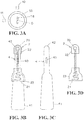
- FIG. 3A is an explanatory view illustrating IC tags and a lock mechanism.
- Fig. 3B is an explanatory view illustrating a detector and a lock operation tool.
- Fig. 3C is an explanatory view illustrating the lock operation tool.
- Fig. 3D is an explanatory view illustrating the detector.
- the aforementioned lock mechanism 5 is a lock mechanism to lock or unlock the door 51 as a second object to or from a wall 50 as a first object.
- the aforementioned lock mechanism 5 includes a lock receiving portion 52, a cylinder 53, and a lock body 54.
- the inner side of the door 51 is attached to the inner side of an opening portion 55 of the wall 50 via hinges 56 so as to be openable and closable.
- important apparatuses that should be protected safely, maintenance tools, a control device of a motive power mechanism, construction tools, or the like are stored, but other apparatuses, members, or the like may be stored.
- the lock receiving portion 52 is a hole (rim lock) portion provided in a substantially intermediate portion of a side edge, in a width direction, of the wall 50 forming the opening portion 55. Further, the cylinder 53 is provided in a portion that exists in a middle portion in a height direction and corresponds to the lock receiving portion 52, which is a portion, in the door 51, close to the side edge on the side opposite to the hinges 56.
- the cylinder 53 includes a shaft member 57 rotatable about a rotation axis O with respect to the door 51.
- the lock body 54 is attached on the shaft member 57.
- the lock operation tool 4 is to make the lock mechanism 5 act to be locked by performing the locking operation (see Fig. 1A and Fig. 2A ), and is to make the lock mechanism 5 act to be unlocked by performing the unlocking operation (see Fig. 1B and Fig. 2B ).
- the detection part 20 of the detector 2 is composed of a one-time or plural-times wound coil.
- the detection part 20 is a part to enable electromagnetic induction communication with each antenna portion of the IC tags 10, 11 by being brought close to each antenna portion of the IC tags 10, 11.
- the detection part 20 is attached to the detection portion 42 of the lock operation tool 4 via the first attachment part 22. Further, the detection part 20 is protected by being covered with the first attachment part 22.
- the lock operation tool 4 is preferably made of metal. That is, this is to make the radiated radio waves radiate to the free space while the radiated radio waves propagating on the surface (metal surface) of the metal lock operation tool 4 as a surface wave.
- the lock operation tool 4 is not limited to the one made of metal, and may be formed of another material.
- the IC tag 10 on one side is attached to a portion to which the detection part 20 (to be described later) of the detection portion 42 approaches and faces to the IC tag 10 when the lock mechanism 5 is brought into a locked state in a state of the key portion 40 being inserted in the keyhole 58.
- the IC tag 11 on the other side is attached to a portion to which the detection part 20 of the detection portion 42 approaches and faces to the IC tag 11 when the lock mechanism 5 is brought into an unlocked state in a state of the key portion 40 being inserted in the keyhole 58.
- a word such as "close” is sometime added, and in the vicinity of the aforementioned IC tag 11 on the other side, an index such as a character of "open” or the like is sometimes added.
- one example of the distance where the IC tag and the detection part 20 are approached and faced is preferably set to about 5 mm or less because it enables more secure discrimination. However, the distance is not limited to about 5 mm or less.
- the distance may be farther than 5 mm, which is, for example, 30 mm or less, 25 mm or less, 20 mm or less, 15 mm or less, or the like, as long as secure discrimination is enabled between the IC tag 10 on one side and the IC tag 11 on the other side.
- the reading device 3 is a portable type (handy type) that a worker (not illustrated) to operate carries in the constitution illustrated in Fig. 1A and Fig. 1B .
- the reading device 3 may be attached to the operation portion 41 of the lock operation tool 4 attachably and detachably.
- the reading device 3 can be connected to a computer network such as the Internet, but may be set to one unconnectable to a computer network.
- the lock information and the unlocking information read by the reading device 3 may be set to be storable in an external database different from the reading device 3.
- the states illustrated in Fig. 1A and Fig. 2A are that the lock mechanism 5 is in a lock acting state and the door 51 is in a state of being closed to the wall 50. There will be explained operation and action to open the door 51 from the wall 50 in this state.
- the operation portion 41 of the lock operation tool in a lock operation state illustrated in Fig. 1B and Fig. 2B is held to rotate clockwise the lock operation tool 4 around the rotation axis O.
- the cylinder 53, the shaft member 57, and the lock body 54 of the lock mechanism 5 rotate clockwise around the rotation axis O. Therefore, as illustrated in Fig. 1A and Fig. 2A , the lock body 54 is fitted in the lock receiving portion 52 in the wall 50 side to be locked. This makes it possible to close the door 51 to the wall 50.
- the lock operation tool 4 is normally stored in a place different from the lock mechanism 5, and when the lock mechanism 5 is locked or unlocked, the lock operation tool 4 is taken out to the lock mechanism 5 from the storage place.
- this is significant when it becomes difficult to visually observe the indexes such as characters of "close,” “open,” and so on added to the door 51 due to getting dirty, recoating being performed thereon, or the like.
- the IC tags 10, 11 are each attached to the outer periphery side of the cylinder 53 of the lock mechanism 5 on the door 51 by being fitted in the hole for fitting or by being bonded thereto by an adhesive (not illustrated) or the like as an attachment part. Therefore, the door 51 of the existing lock mechanism 5 can be equipped with the IC tags 10, 11, and thus the door 51 of the existing lock mechanism 5 can be used, thereby making it possible to achieve the reduction in cost.
- the lock mechanism 5 equipped with the IC tags 10, 11 according to this embodiment 1 may be manufactured newly.
- the detector 2 includes the antenna part 21 with the wire length of ⁇ /4, which is made by being bent back a plurality of times.
- the lock operation tool 4 is constituted to include the detection part 20 on one side of the lock operation tool 4 and the antenna part 21 on the other side of the lock operation tool 4 across the key portion 40, resulting in that it is also possible to dispose the antenna part 21 closer to a hand at the operation portion 41 compactly. Accordingly, according to the compact constitution of the antenna part 21 having a portion bent back a plurality of times and the small-sized detector 2, as compared to the case including a large-sized antenna part, it is possible to improve operationality of the detector 2 and improve the workability.
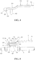
- Fig. 4 is a view illustrating the detection device, the detection system, the operation tool, and the mechanism according to the second embodiment of the present invention.
- the same reference numerals and symbols as those in Fig. 1A and Fig. 1B to Fig. 3A to Fig. 3D denote the same components.
- a detector 2A includes a detection part 20 and a wire portion 24 connecting the detection part 20 and the reading device 3 (see Fig. 1A and Fig. 1B ).
- the wire portion 24 has a role as a cable for performing wire communication between the detection part 20 and the aforementioned reading device.
- the wire portion 24 is wired. That is, the wire portion 24 is internally wired between one end portion of a detection portion 42 and the other end portion of an operation portion 41. Furthermore, the wire portion 24 is led out to the outside from the other end portion of the operation portion 41, and the wire portion 24 is connected to the reading device 3.
- the detection device, the detection system, the operation tool, and the mechanism according to this embodiment each are constituted as above, thus making it possible to achieve the functions and the effects substantially similar to those of the respective devices and the like 10, 11, 2, 3, 4, and 5 according to the first embodiment.
- the detector 2A according to this embodiment and the reading device 3 communicate with each other by wire, and thus as compared to radio communication, it is possible to securely read information considering that, for example, security is important, or the like with high accuracy, resulting in that high-quality and highly accurate confirmation and management (recognition and management) can be obtained.
- Fig. 5 to Fig. 10A to Fig. 10D are views illustrating the detection device, the detection system, the operation tool, and the mechanism according to the third embodiment of the present invention.
- the same reference numerals and symbols as those in Fig. 1A and Fig. 1B to Fig. 4 denote the same components.
- Fig. 10A is an explanatory view illustrating IC tags 10, 11, a pipe valve mechanism 6, and a display plate 64.
- Fig. 10B is an explanatory view illustrating a detector 2 and a valve operation tool 7.
- Fig. 10C is an explanatory view illustrating the valve operation tool 7.
- Fig. 10D is an explanatory view illustrating the detector 2.
- the detection device includes a plurality of pieces of the IC tags 10, 11, which are two, for example, the detector 2, and the reading device 3.
- the detection system includes the valve operation tool 7 as the operation tool, the pipe valve mechanism 6, as the mechanism, and the detection devices 10, 11, 2, and 3 according to the first embodiment.
- the pipe valve mechanism 6 is provided on the way of a pipe 60, and is a mechanism that closes a valve (not illustrated) to stop the flow of fluid such as liquid or gas (not illustrated) in the pipe 60 or opens the valve to let the fluid in the pipe 60 flow.
- the pipe valve mechanism 6 includes a valve main body 61, the valve, an open/close shaft 62, and a stopper 63.
- the valve main body 61 is provided on the way of the pipe 60. Inside the valve main body 61, the not-illustrated valve is accommodated so as to be openable and closable. One end of the open/close shaft 62 is coupled to this valve. The other end portion of the open/close shaft 62 projects to the outside from the valve main body 61.
- a shape of the other end portion of the open/close shaft 62 in plan view is a shape other than a circular shape, and is an oval shape in this example.
- the open/close shaft 62 is rotated around the rotation axis O, thereby making it possible to open or close the valve.
- the stopper 63 has a quadrangular columnar shape, and is provided on the above-described valve main body 61.
- the open/close shaft 62 and the stopper 63 are parallel or substantially parallel each other.
- the valve operation tool 7 is to operate opening and closing actions of the valve of the pipe valve mechanism 6.
- the valve operation tool 7 includes, as illustrated in Fig. 10C , an engaging portion 70, an operation portion 71 being one end portion, a detection portion 72 being the other end portion, a close stopper 73, and an open stopper 74.
- the other end portion is used both as the detection portion 72 and the open stopper 74.
- the engaging portion 70 has an oval-shaped engaging hole 75.
- the oval-shaped other end portion of the open/close shaft 62 is fitted in the engaging hole 75.
- the operation portion 71 is a portion for rotating the engaging portion 70 to open or close the valve of the pipe valve mechanism 6.
- an antenna part 21 connected to the detector 2 is attached via a second attachment part 23 as an attachment part.
- a detection part 20 of the detector 2 is disposed via an adhesive as an attachment part, another attachment structure, or the like.
- the operation portion 71 extends from the engaging portion 70 toward the side opposite to the detection part 20 side. This makes it possible to prevent a hand or the like of an operator from being caught in between the operation portion 71 of the valve operation tool 7 and the pipe 60 of the pipe valve mechanism 6.
- the close stopper 73 and the open stopper 74 that are described above are provided integrally in the engaging portion 70. Further, the other end portion is used both as the detection portion 72 and the open stopper 74. Among them, the close stopper 73 abuts on the stopper 63 of the pipe valve mechanism 6 at the time of a close operation of the valve operation tool 7 as illustrated in Fig. 9 . Further, the open stopper 74, together with the detection portion 72, abuts on the stopper 63 of the pipe valve mechanism 6 at the time of an open operation of the valve operation tool 7 as illustrated in Fig. 7 .
- the two IC tags 10, 11 are each attached to the pipe valve mechanism 6 via the display plate 64 as an attachment part.
- information on an operation state of the valve operation tool 7 and information on an acting state of the pipe valve mechanism 6 are each stored. That is, in the IC tag 10 on one side, information on a close operation state of the valve operation tool 7 and information on a closed acting state of the pipe valve mechanism 6 (to be simply referred to as "close information” hereinafter) are stored.
- close information information on a close operation state of the valve operation tool 7 and information on a closed acting state of the pipe valve mechanism 6
- open information to as "open information” hereinafter
- information other than the close information and the open information for example, individual information of the pipe valve mechanism 6 and so on are stored.
- the detector 2 includes the detection part 20 and the antenna part 21 as illustrated in Fig. 10D .
- the detector 2 is attached to the valve operation tool 7 via an adhesive as an attachment part or the second attachment part 23 as illustrated in Fig. 10B .
- the detector 2 is a part to detect each of the close information and the open information in the two IC tags 10, 11.
- the display plate 64 has a plate shape that substantially covers the valve main body 61 of the pipe valve mechanism 6.
- the display plate 64 may have a panel shape that extensively covers the pipe 60 of the pipe valve mechanism 6.
- a circular through hole 65 and a rectangular insertion hole 66 are provided in the display plate 64. Further, to the display plate 64, the two IC tags 10, 11 are attached. On the display plate 64, in the vicinity of the IC tag 10 on one side, an index such as a character of "close” or the like is sometimes added, and in the vicinity of the IC tag 11 on the other side, an index such as a character of "open” or the like is sometimes added.
- the display plate 64 is fixed to the valve main body 61 of the pipe valve mechanism 6 as illustrated in Fig. 10A .
- the open/close shaft 62 of the pipe valve mechanism 6 is inserted in a rotatable state.
- the stopper 63 of the pipe valve mechanism 6 is inserted in the insertion hole 66 of the display plate 64.
- the detection devices 10, 11, 2, and 3, the valve operation tool 7, and the pipe valve mechanism 6 having such constitutions as above can create the following functions.
- Fig. 9 The state illustrated in Fig. 9 is that the pipe valve mechanism 6 is in a closed acting state and the valve is in a closed state. There will be explained operation and action to open the valve in this state.
- the engaging hole 75 in the engaging portion 70 of the valve operation tool 7 is engaged with the open/close shaft 62 of the pipe valve mechanism 6 in a closed acting state illustrated in Fig. 9 .
- the detection part 20 of the detector 2 disposed on the detection portion 72 of the valve operation tool 7 and the IC tag 10 on one side disposed on the display plate 64 are approached and faced each other.
- the close information stored in the IC tag 10 on one side is detected by the detector 2 and is read by the reading device 3. This makes it possible to securely confirm and manage (recognize and manage) that the valve operation tool 7 is in a close operation state and the pipe valve mechanism 6 is in a closed acting state.
- the operation portion 71 of the valve operation tool 7 is held to rotate counterclockwise the valve operation tool 7 around the rotation axis O. Then, the open/close shaft 62 of the pipe valve mechanism 6 rotates counterclockwise around the rotation axis O to be brought into an open state illustrated in Fig. 7 . Thereby, the valve is opened.
- the detection part 20 of the detector 2 disposed on the detection portion 72 of the valve operation tool 7 and the IC tag 11 on the other side disposed on the display plate 64 are approached and faced each other. Then, the open information stored in the IC tag 11 on the other side is detected by the detector 2 and is read by the reading device 3. This makes it possible to securely confirm and manage (recognize and manage) that the valve operation tool 7 is in an open operation state and the pipe valve mechanism 6 is in an opened acting state.
- the operation portion 71 of the valve operation tool 7 in the open operation state illustrated in Fig. 7 is held to rotate clockwise the valve operation tool 7 around the rotation axis O. Then, the open/close shaft 62 of the pipe valve mechanism 6 rotates counterclockwise around the rotation axis O to be brought into a closed state illustrated in Fig. 9 . Thereby, the valve is closed.
- the detection part 20 of the detector 2 disposed on the detection portion 72 of the valve operation tool 7 and the IC tag 10 on one side disposed on the display plate 64 are approached and faced each other as described above.
- the close information stored in the IC tag 10 on one side is read by the reading device 3 via the detector 2, and then it is possible to securely confirm and manage (recognize and manage) the close operation state of the valve operation tool 7 and the closed acting state of the pipe valve mechanism 6.
- valve operation tool 7 is normally stored in a place different from the pipe valve mechanism 6. Then, when the pipe valve mechanism 6 is opened or closed, the valve operation tool 7 is taken out to the pipe valve mechanism 6 from the storage place, and the above-described open or close operation is performed.
- the detection devices 10, 11, 2, 3, 6, and 7 and the like according to this embodiment 3 each have the above-described constitution and functions, and their effects will be explained below.
- the respective devices 10, 11, 2, 3, 6, and 7 and the like according to this embodiment can securely confirm and manage (recognize and manage) the operation state of the valve operation tool 7 and the acting state of the pipe valve mechanism 6 in association with each other relatively. Therefore, the respective devices 10, 11, 2, 3, 6, and 7 and the like according to this embodiment can reduce the increase in cost due to multiple checks performed by a plurality of people because human errors caused by human visual observation are reduced.
- the detector 2 is disposed on the valve operation tool 7 via an adhesive or the second attachment part 23. Therefore, it is possible to equip the existing valve operation tool 7with the detector 2, and thus the existing valve operation tool 7 can be used, thereby making it possible to achieve the reduction in cost.
- the valve operation tool 7 equipped with the detector 2 according to this embodiment may be manufactured newly.
- the IC tags 10, 11 are disposed on the pipe valve mechanism 6 via the display plate 64 as an attachment part. Therefore, the existing pipe valve mechanism 6 can be equipped with the IC tags 10, 11, and thus the existing pipe valve mechanism 6 can be used, thereby making it possible to achieve the reduction in cost. Incidentally, the pipe valve mechanism 6 equipped with the IC tags 10, 11 according to this embodiment may be manufactured newly.
- Fig. 11A to Fig. 11C are views for explaining modified examples 1 to 3 of the present invention.
- detection devices detection systems, operation tools, mechanisms according to the modified examples 1 to 3 (to be simply referred to as “detection devices and the like" hereinafter).
- the detection devices and the like according to the above-described first to third embodiments are that the lock operation tool 4 or 4A or the valve operation tool 7 is rotated around the rotation axis O between the two points (the locked position and the unlocked position or the close position and the open position) to actuate the lock mechanism 5 or the pipe valve mechanism 6.
- the detection devices and the like according to the modified example 1 such as an operation tool 82 to control rotational directions of a rotary power device, actuate the mechanism by switching the position between the three positions as illustrated in Fig. 11A , in which the operation tool 82 is operated and rotated between three positions (an IC tag 12L at the left position, an IC tag 12N at the neutral position, and an IC tag 12R at the right position) around the rotation axis O.
- a rotation angle may be rotation angles other than 90° illustrated in Fig. 11A .
- the number of operation positions may be four or more other than three.
- the detection devices and the like according to the modified example 2 are that an operation tool 83 is linearly operated between three points (an IC tag 13L at the left position, an IC tag 13N at the neutral position, and an IC tag 13R at the right position) to actuate the mechanism by switching the position between the three positions as illustrated in Fig. 11B .
- the length of a straight line may be lengths other than the length illustrated in Fig. 11A .
- the number of operation positions may be four or more other than three.
- the operation is not limited to the linear operation, but may be curve operation, and the linear operation and the curve operation may be combined.
- the present invention is not limited by the above-described first to third embodiments and modified examples 1 to 3.
- the present invention may be applied to a portion to open and close a toolbox or the like attached to the outside of a construction machine, or the present invention may be applied to an opening/closing mechanism for other external infrastructures or storage doors, protective doors, and the like of important control apparatuses of moving vehicles such as a train, shipping, and aircraft.
- the present invention may be constituted to include a computer (server, or the like) for managing pieces of the information stored in the IC tags.
- the IC tag is made to cooperate with a checklist including an ID on the computer side and information corresponding to it or the like, and the IC tag is set as a virtual memory not having memory information.
Landscapes
- Engineering & Computer Science (AREA)
- General Engineering & Computer Science (AREA)
- Physics & Mathematics (AREA)
- General Physics & Mathematics (AREA)
- Mechanical Engineering (AREA)
- Life Sciences & Earth Sciences (AREA)
- Geophysics (AREA)
- General Life Sciences & Earth Sciences (AREA)
- Electromagnetism (AREA)
- Computer Vision & Pattern Recognition (AREA)
- Artificial Intelligence (AREA)
- Theoretical Computer Science (AREA)
- Toxicology (AREA)
- General Health & Medical Sciences (AREA)
- Health & Medical Sciences (AREA)
- Environmental & Geological Engineering (AREA)
- Geology (AREA)
- Remote Sensing (AREA)
- Indication Of The Valve Opening Or Closing Status (AREA)
- Preventing Unauthorised Actuation Of Valves (AREA)
- Lock And Its Accessories (AREA)
Abstract

Description
- The present invention relates to a detection device, a detection system, a detection system operation tool, and a detection system mechanism.
- Among various infrastructures and so on, there exists one with an IC tag attached thereto as described in
PTL 1, for example. InPTL 1, avalve 2 is attached to a pipe disposed under the ground, and a socket fittingpart 1 is provided on thevalve 2. AnIC tag 7 is attached to the socket fittingpart 1. Further, on avalve switch 3, alock mechanism 5 having a loop antenna 8 is provided, and thevalve switch 3 is inserted from the ground, thereby making it possible to acquire information of theIC tag 7 and perform a switching operation of thevalve 2. - {PTL 1}
JP 2015-109507 - By the way, in the constitution disclosed in
PTL 1, it is possible to read information (an individual identification number, a lower closing direction, an installation place, an installation year, and so on) of thevalve 2 from theIC tag 7. However, it is impossible to judge to which of the open position or the close position thevalve 2 has been rotated actually. - There exists the similar problem other than the valve. That is, under the present circumstances, in a mechanical device capable of switching between an open position and a close position by a rotation operation of a rotation part, there hardly exists a method of judging to either position the rotation part has been rotated other than the visual judging method actually. Concretely, to confirm the open position or the close position is often performed by visually confirming an index such as a character indicating "open" or "close" existing near the rotation part.
- However, in the case where the confirmation of the open position or the close position is performed by visual observation, the visual observation is difficult to be performed when, for example, the vicinity of the rotation part is dirty (due to, for example, grease, rust occurrence, dirt attachment, or the like), it is coated newly, or the like. In these cases, it sometimes takes time to remove the dirt, peel the coating, or the like, additionally. Further, in the case where the above-described dirt or recoating is not removed, with difficulty in recognizing the index, there is caused such a problem as occurrence of a switching miss between the open position and the close position. Further, in plant sites, shipping, trains, aircraft, or the like, there are a considerable number of places to confirm open and close positions of storage and protective covers of important devices, and in a simple work such as a visual inspection of an open/close state, mistakes such as miss viewing and visual oversight are also concerned.
- Further, even in the case where the dirt or recoating does not exist near the rotation part, a worker sometimes falsely recognizes the open position and the close position due to his/her human error. In the case where multiple checks are performed by a plurality of people in order to prevent such false recognition, there is also a problem that an increase in cost is caused accordingly. Further, when it is not clear where the rotation part is, in the case where an operation tool is actually used to operate the rotation part, there are also problems that a state of the operation and an acting state of an acting mechanism including the rotation part are not clear.
- The present invention has been made in consideration of the above-described circumstances, and an object thereof is to provide a detection device, a detection system, an operation tool, and a detection system mechanism that are capable of simultaneously detecting an operation state of the operation tool and an acting state of the mechanism actuated by operation of the operation tool as well as detecting whether a rotation part is at an open position or at a close position.
- In order to solve the above-described problems, according to the first aspect of the present invention, there is provided a detection device being a device that detects an operation state of an operation tool and an acting state of a mechanism to act by operation of the operation tool, the detection device including: a plurality of pieces of IC tags that are disposed on the mechanism and each have information of the operation state of the operation tool and information of the acting state of the mechanism stored therein; a detector that is disposed on the operation tool and detects each of the pieces of information in the plurality of pieces of the IC tags; and a reading device that reads the pieces of information detected by the detector.
- Further, according to another aspect of the present invention, in the above-described invention, preferably the detector is attached to the operation tool via an attachment part.
- Furthermore, according to another aspect of the present invention, in the above-described invention, preferably the plurality of pieces of the IC tags are each attached to the mechanism via an attachment part.
- Further, according to another aspect of the present invention, in the above-described invention, preferably the detector includes: a detection part that detects each of the pieces of information in the plurality of pieces of the IC tags; and an antenna part that communicates with the reading device by radio.
- Furthermore, according to another aspect of the present invention, in the above-described invention, preferably in the case where a wavelength of electromagnetic waves to be used for communication with the IC tag is set to λ, the antenna part in the detector is formed by a wire that has a length of an integral multiple of λ/4 being bent back a plurality of times.
- Further, according to another aspect of the present invention, in the above-described invention, preferably the detector includes: a detection part that detects each of the pieces of information in the plurality of pieces of the IC tags; and a wire portion that communicates with the reading device by wire.
- Furthermore, according to another aspect of the present invention, preferably it includes: an operation tool; a mechanism that acts by operation of the operation tool; and the detection device according to each of the above-described inventions.
- Further, according to another aspect of the present invention, in the above-described invention, preferably the mechanism is a lock mechanism that locks or unlocks a second object to or from a first object, and the operation tool is a lock operation tool that operates a locked state and an unlocked state of the lock mechanism.
- Furthermore, according to another aspect of the present invention, preferably the lock mechanism according to each of the above-described inventions is a lock mechanism for door that includes: a lock receiving portion provided in a wall as the first object; and a cylinder and a lock body that are provided in a door as the second object and locks or unlocks the lock body in or from the lock receiving portion via the cylinder, and the lock operation tool is a lock operation tool for door that includes: a key portion to be inserted in the cylinder; an operation portion that operates the key portion to lock or unlock the lock mechanism for door; and a detection portion on which the detector is disposed.
- Further, according to another aspect of the present invention, in the above-described invention, preferably the mechanism is a pipe valve mechanism that is provided in the middle of a pipe, closes a valve to stop flow of a fluid in the pipe, and opens the valve to let the fluid in the pipe flow, and the operation tool is a valve operation tool that operates a closed state and an open state of the valve of the pipe valve mechanism.
- Furthermore, according to another aspect of the present invention, in the above-described invention, preferably the pipe valve mechanism includes: a valve main body provided in the middle of the pipe; the valve stored in the valve main body so as to be openable and closable; an open/close shaft coupled to the valve, projecting to the outside from the valve main body, and opening and closing the valve; and a stopper provided on the valve main body, and the valve operation tool is a valve operation tool including: an engaging portion that engages with the open/close shaft; an operation portion that operates the engaging portion; a detection portion on which a detector is disposed; a close stopper that abuts on the stopper at the time of a close operation of the valve operation tool; and an open stopper that abuts on the stopper at the time of an open operation of the valve operation tool.
- Further, according to another aspect of the present invention, preferably the operation tool according to each of the above-described inventions has a detector attached thereto via an attachment part.
- Furthermore, according to another aspect of the present invention, preferably the mechanism according to each of the above-described inventions has a plurality of pieces of IC tags each attached thereto via an attachment part.
- According to the present invention, it becomes possible to securely judge whether a rotation part is at an open position or at a close position.
-
- {
Fig. 1A and Fig. 1B } are views illustrating a detection device, a detection system, an operation tool, and a mechanism according to a first embodiment of the present invention,Fig. 1A is an explanatory view illustrating a use state (closed state of a door), andFig. 1B is an explanatory view illustrating a use state (open state of the door). - {
Fig. 2A and Fig. 2B } are cross-sectional views illustrating use states of the detection device, the detection system, the operation tool, and the mechanism inFig. 1A and Fig. 1B ,Fig. 2A illustrates the use state (closed state of the door), andFig. 2B illustrates the use state (open state of the door). - {
Fig. 3A to Fig. 3D } are explanatory views illustrating IC tags, a detector, a lock operation tool, and a lock mechanism,Fig. 3A is the explanatory view illustrating the IC tags and the lock mechanism,Fig. 3B is the explanatory view illustrating the detector and the lock operation tool,Fig. 3C is the explanatory view illustrating the lock operation tool, andFig. 3D is the explanatory view illustrating the detector. - {
Fig. 4 } is an explanatory view of a detector and a lock operation tool that illustrates a detection device, a detection system, an operation tool, and a mechanism according to a second embodiment of the present invention. - {
Fig. 5 } is an explanatory side view of a use state that illustrates a detection device, a detection system, an operation tool, and a mechanism according to a third embodiment of the present invention. - {
Fig. 6 } is an explanatory exploded side view of IC tags, a detector, a valve operation tool, and a pipe valve mechanism illustrated inFig. 5 . - {
Fig. 7 } is an explanatory plane view illustrating a use state of the detection device, the detection system, the operation tool, and the mechanism illustrated inFig. 5 (an open state of a valve). - {
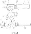
Fig. 8 } is an exploded explanatory plane view illustrating the IC tags, the detector, the valve operation tool, and the pipe valve mechanism illustrated inFig. 5 . - {
Fig. 9 } is an explanatory plane view illustrating a use state of the detection device, the detection system, the operation tool, and the mechanism illustrated inFig. 5 (a closed state of the valve). - {
Fig. 10A to Fig. 10D } are views according to the third embodiment,Fig. 10A is an explanatory view illustrating the IC tags, the pipe valve mechanism, and a display plate,Fig. 10B is an explanatory view illustrating the detector and the valve operation tool,Fig. 10C is an explanatory view illustrating the valve operation tool, andFig. 10D is an explanatory view illustrating the detector. - {
Fig. 11A to Fig. 11C } are explanatory views illustrating detection devices, detection systems, operation tools, and mechanisms according to modified examples of the present invention. - Hereinafter, there will be explained three embodiments (first to third embodiments) and modified examples of the detection device, the detection system, the operation tool, and the mechanism according to this invention in detail based on the drawings.
-
Fig. 1A and Fig. 1B toFig. 3A to Fig. 3D are views illustrating the detection device, the detection system, the operation tool, and the mechanism according to the first embodiment of the present invention. Hereinafter, there will be explained constitutions of the detection device, the detection system, the operation tool, and the mechanism according to thisembodiment 1.Fig. 1A is an explanatory view illustrating a use state (closed state of a door 51).Fig. 1B is an explanatory view illustrating a use state (open state of the door 51).Fig. 2A is a cross-sectional view illustrating the use state (closed state of the door 51).Fig. 2B is a cross-sectional view illustrating the use state (open state of the door 51).Fig. 3A is an explanatory view illustrating IC tags and a lock mechanism.Fig. 3B is an explanatory view illustrating a detector and a lock operation tool.Fig. 3C is an explanatory view illustrating the lock operation tool.Fig. 3D is an explanatory view illustrating the detector. - The detection device according to this embodiment includes a plurality of pieces (as one example, two pieces) of IC tags 10, 11, a
detector 2, and areading device 3. The detection system according to this embodiment includes, as the operation tool, a lock operation tool for door (to be simply referred to as a "lock operation tool" hereinafter) 4, as the mechanism, a lock mechanism for door (to be simply referred to as a "lock mechanism" hereinafter) 5, anddetection devices - The
aforementioned lock mechanism 5 is a lock mechanism to lock or unlock thedoor 51 as a second object to or from awall 50 as a first object. Theaforementioned lock mechanism 5 includes alock receiving portion 52, acylinder 53, and alock body 54. The inner side of thedoor 51 is attached to the inner side of anopening portion 55 of thewall 50 viahinges 56 so as to be openable and closable. Incidentally, inside theaforementioned opening portion 55, important apparatuses that should be protected safely, maintenance tools, a control device of a motive power mechanism, construction tools, or the like are stored, but other apparatuses, members, or the like may be stored. - The
lock receiving portion 52 is a hole (rim lock) portion provided in a substantially intermediate portion of a side edge, in a width direction, of thewall 50 forming the openingportion 55. Further, thecylinder 53 is provided in a portion that exists in a middle portion in a height direction and corresponds to thelock receiving portion 52, which is a portion, in thedoor 51, close to the side edge on the side opposite to thehinges 56. Thecylinder 53 includes ashaft member 57 rotatable about a rotation axis O with respect to thedoor 51. Thelock body 54 is attached on theshaft member 57. - Further, by operating the
lock operation tool 4 to rotate theshaft member 57 of thecylinder 53 around the rotation axis O, thelock body 54 rotates around the rotation axis O and fits into thelock receiving portion 52 or comes off from thelock receiving portion 52. That is, by a locking operation of thelock operation tool 4, thelock mechanism 5 acts to be locked (seeFig. 1A andFig. 2A ), and by an unlocking operation of thelock operation tool 4, thelock mechanism 5 acts to be unlocked (seeFig. 1B andFig. 2B ). - The
lock operation tool 4 includes, as illustrated inFig. 3C , akey portion 40 being a substantially intermediate portion, anoperation portion 41 being one end portion, and adetection portion 42 being the other end portion. - Among them, the
key portion 40 is a portion to be inserted into akeyhole 58 of thecylinder 53. Further, theoperation portion 41 is a portion to rotate thekey portion 40. Further, in thedetection portion 42, thedetector 2 is disposed. The longitudinal direction of the above-describedoperation portion 41 and the longitudinal direction of thekey portion 4 are substantially perpendicular each other. That is, theoperation portion 41 is bent substantially perpendicularly to thekey portion 40 so as to extend to the side opposite to thedetection portion 42. - Further, the
lock operation tool 4 is to make thelock mechanism 5 act to be locked by performing the locking operation (seeFig. 1A andFig. 2A ), and is to make thelock mechanism 5 act to be unlocked by performing the unlocking operation (seeFig. 1B andFig. 2B ). - As illustrated in
Fig. 3A , the twoIC tags cylinder 53 of thelock mechanism 5 on thedoor 51, where the twoIC tags IC tags lock operation tool 4 and information on an acting state of thelock mechanism 5 are each stored. That is, in theIC tag 10 on one side, the information corresponding to locking of the lock operation tool 4 (to be simply referred to as "lock information" hereinafter) is stored. Further, in theaforementioned IC tag 11 on the other side, the information corresponding to unlocking of the lock operation tool 4 (to be simply referred to as "unlocking information" hereinafter) is stored. - These two
IC tags lock mechanism 5, and so on are stored. - Further, as illustrated in
Fig. 3D , thedetector 2 includes adetection part 20 and anantenna part 21. As illustrated inFig. 3B , thedetector 2 is attached to thelock operation tool 4 via afirst attachment part 22 and asecond attachment part 23 as attachment parts. Further, thedetector 2 is a part to detect each of the lock information and the unlocking information in the twoIC tags - The
detection part 20 of thedetector 2 is composed of a one-time or plural-times wound coil. Thedetection part 20 is a part to enable electromagnetic induction communication with each antenna portion of the IC tags 10, 11 by being brought close to each antenna portion of the IC tags 10, 11. Thedetection part 20 is attached to thedetection portion 42 of thelock operation tool 4 via thefirst attachment part 22. Further, thedetection part 20 is protected by being covered with thefirst attachment part 22. - Further, the
antenna part 21 is provided to extend from one end of the coil-shapeddetection part 20. In the case where the wavelength of electromagnetic waves used for the communication with the IC tags 10, 11 is set to λ, a wire length of theantenna part 21 is set to, for example, λ/4 as one example. Further, theantenna part 21 is formed by being bent back a plurality of times. However, when the wire length of theantenna part 21 is not a problem, theantenna part 21 may have a straight shape. Further, theantenna part 21 may be provided on thelock operation tool 4 so as to wind therearound without being bent back. Further, the wire length of theantenna part 21 may be set to an integral multiple larger than 1 of λ/4 (the same is true of the other embodiments). - The
antenna part 21 communicates with thereading device 3 by radio with induced electromagnetic waves, radiated radio waves, or the like. Further, theantenna part 21 is attached to a portion between thekey portion 40 and theoperation portion 41 of thelock operation tool 4 via thesecond attachment part 23. Theantenna part 21 is protected by being covered with thesecond attachment part 23. - Here, in the case where the
detector 2 communicates with thereading device 3 by radio with the radiated radio waves, thelock operation tool 4 is preferably made of metal. That is, this is to make the radiated radio waves radiate to the free space while the radiated radio waves propagating on the surface (metal surface) of the metallock operation tool 4 as a surface wave. However, thelock operation tool 4 is not limited to the one made of metal, and may be formed of another material. - Incidentally, a wire may be extended straight from the other end of the coil of the coil-shaped
detection part 20 to have a wire length of λ/4. In this case, the wire and theantenna part 21 are preferably formed of an insulation-coated wire. - The two aforementioned IC tags 10, 11 and the
detector 2 are disposed at positions where the operation state of thelock operation tool 4 and the acting state of thelock mechanism 5 correspond each other. - That is, the
IC tag 10 on one side is attached to a portion to which the detection part 20 (to be described later) of thedetection portion 42 approaches and faces to theIC tag 10 when thelock mechanism 5 is brought into a locked state in a state of thekey portion 40 being inserted in thekeyhole 58. Further, theIC tag 11 on the other side is attached to a portion to which thedetection part 20 of thedetection portion 42 approaches and faces to theIC tag 11 when thelock mechanism 5 is brought into an unlocked state in a state of thekey portion 40 being inserted in thekeyhole 58. Incidentally, on thedoor 51, in the vicinity of theIC tag 10 on one side, a word such as "close" is sometime added, and in the vicinity of theaforementioned IC tag 11 on the other side, an index such as a character of "open" or the like is sometimes added. Incidentally, one example of the distance where the IC tag and thedetection part 20 are approached and faced is preferably set to about 5 mm or less because it enables more secure discrimination. However, the distance is not limited to about 5 mm or less. That is, the distance may be farther than 5 mm, which is, for example, 30 mm or less, 25 mm or less, 20 mm or less, 15 mm or less, or the like, as long as secure discrimination is enabled between theIC tag 10 on one side and theIC tag 11 on the other side. - As illustrated in
Fig. 1A and Fig. 1B , thereading device 3 includes an antenna portion (not illustrated), a reader IC portion (not illustrated), a microcomputer portion (not illustrated), an operation portion, and a display portion. Thereading device 3 communicates with thedetector 2 by radio by the antenna portion on thereading device 3 side and theantenna part 21 on thedetector 2 side. Further, thereading device 3 reads the lock information and the unlocking information detected by thedetector 2. Incidentally, thereading device 3 may be provided with a writing function. - The
reading device 3 is a portable type (handy type) that a worker (not illustrated) to operate carries in the constitution illustrated inFig. 1A and Fig. 1B . Incidentally, thereading device 3 may be attached to theoperation portion 41 of thelock operation tool 4 attachably and detachably. Further, thereading device 3 can be connected to a computer network such as the Internet, but may be set to one unconnectable to a computer network. Further, the lock information and the unlocking information read by thereading device 3 may be set to be storable in an external database different from thereading device 3. - The
detection devices lock operation tool 4, and thelock mechanism 5 having such constitutions as above (to be simply referred to as the "detection devices and the like 10, 11, 2, 3, 4, and 5" hereinafter) can create the following functions. - The states illustrated in
Fig. 1A andFig. 2A are that thelock mechanism 5 is in a lock acting state and thedoor 51 is in a state of being closed to thewall 50. There will be explained operation and action to open thedoor 51 from thewall 50 in this state. - First, the
key portion 40 of thelock operation tool 4 is inserted in thekeyhole 58 of thecylinder 53 of thelock mechanism 5 on thedoor 51 side in a lock acting state illustrated inFig. 1A andFig. 2A . At this time, thedetection part 20 of thedetector 2 disposed on thedetection portion 42 of thelock operation tool 4 and theIC tag 10 on one side disposed on thedoor 51 are approached and faced each other. Then, the lock information stored in theIC tag 10 on one side is detected by thedetector 2 and is read by thereading device 3. This makes it possible to securely confirm and manage (recognize and manage) that thelock operation tool 4 is in a lock operation state and thelock mechanism 5 is in a lock acting state. - Next, the
operation portion 41 of thelock operation tool 4 is held to rotate counterclockwise thelock operation tool 4 around the rotation axis O inFig. 1A . Then, thecylinder 53, theshaft member 57, and thelock body 54 of thelock mechanism 5 rotate counterclockwise around the rotation axis O. Thereby, as illustrated inFig. 1B andFig. 2B , thelock body 54 is disengaged from thelock receiving portion 52 in thewall 50 side to be unlocked. This makes it possible to open thedoor 51 from thewall 50. - At this time, the
detection part 20 of thedetector 2 disposed on thedetection portion 42 of thelock operation tool 4 and theIC tag 11 on the other side disposed on thedoor 51 are approached and faced each other. Then, the unlocking information stored in theIC tag 11 on the other side is detected by thedetector 2 and is read by thereading device 3. This makes it possible to securely confirm and manage (recognize and manage) that thelock operation tool 4 is in an unlocking operation state and thelock mechanism 5 is in an unlock acting state. - Furthermore, the
operation portion 41 of the lock operation tool in a lock operation state illustrated inFig. 1B andFig. 2B is held to rotate clockwise thelock operation tool 4 around the rotation axis O. Then, thecylinder 53, theshaft member 57, and thelock body 54 of thelock mechanism 5 rotate clockwise around the rotation axis O. Therefore, as illustrated inFig. 1A andFig. 2A , thelock body 54 is fitted in thelock receiving portion 52 in thewall 50 side to be locked. This makes it possible to close thedoor 51 to thewall 50. - At this time, as described previously, the
detection part 20 of thedetector 2 disposed on thedetection portion 42 of thelock operation tool 4 and theIC tag 10 on one side disposed on thedoor 51 are approached and faced each other. Thereby, the lock information stored in theIC tag 10 on one side is read by thereading device 3 via thedetector 2, and then it is possible to securely confirm and manage (recognize and manage) the lock operation state of thelock operation tool 4 and the locked acting state of thelock mechanism 5. - Incidentally, the
lock operation tool 4 is normally stored in a place different from thelock mechanism 5, and when thelock mechanism 5 is locked or unlocked, thelock operation tool 4 is taken out to thelock mechanism 5 from the storage place. - As described above, in this embodiment, it is possible to simultaneously detect the operation state such as the rotation of the
lock operation tool 4 and the acting state of thelock mechanism 5 to act by operation of the lock operation tool 4 (for example, an open state or a closed state). Therefore, therespective devices lock operation tool 4 and the acting state of the lock mechanism 5 (for example, the open state, the closed state, or the like) in association with each other relatively. Therefore, therespective devices - In this embodiment in particular, this is significant when it becomes difficult to visually observe the indexes such as characters of "close," "open," and so on added to the
door 51 due to getting dirty, recoating being performed thereon, or the like. - Further, in this embodiment, the
detector 2 is disposed on thelock operation tool 4 via thefirst attachment part 22 and thesecond attachment part 23. Therefore, it is possible to equip the existinglock operation tool 4 with thedetector 2, and thus the existinglock operation tool 4 can be used, thereby making it possible to achieve the reduction in cost. Incidentally, thelock operation tool 4 equipped with thedetector 2 according to this embodiment may be manufactured newly. - Further, in this embodiment, the IC tags 10, 11 are each attached to the outer periphery side of the
cylinder 53 of thelock mechanism 5 on thedoor 51 by being fitted in the hole for fitting or by being bonded thereto by an adhesive (not illustrated) or the like as an attachment part. Therefore, thedoor 51 of the existinglock mechanism 5 can be equipped with the IC tags 10, 11, and thus thedoor 51 of the existinglock mechanism 5 can be used, thereby making it possible to achieve the reduction in cost. Incidentally, thelock mechanism 5 equipped with the IC tags 10, 11 according to thisembodiment 1 may be manufactured newly. - Further, in this embodiment, the
detector 2 and thereading device 3 communicate with each other by radio. Accordingly, as compared to wire communication, cable wires, or the like do not obstruct in the way and workability is improved. - Further, in this embodiment, the
detector 2 includes theantenna part 21 with the wire length of λ/4, which is made by being bent back a plurality of times. By miniaturization by this bending back, thelock operation tool 4 is constituted to include thedetection part 20 on one side of thelock operation tool 4 and theantenna part 21 on the other side of thelock operation tool 4 across thekey portion 40, resulting in that it is also possible to dispose theantenna part 21 closer to a hand at theoperation portion 41 compactly. Accordingly, according to the compact constitution of theantenna part 21 having a portion bent back a plurality of times and the small-sized detector 2, as compared to the case including a large-sized antenna part, it is possible to improve operationality of thedetector 2 and improve the workability. -
Fig. 4 is a view illustrating the detection device, the detection system, the operation tool, and the mechanism according to the second embodiment of the present invention. Hereinafter, there will be explained constitutions, functions, and effects of the detection device, the detection system, the operation tool, and the mechanism according to the second embodiment. Incidentally, inFig. 4 , the same reference numerals and symbols as those inFig. 1A and Fig. 1B toFig. 3A to Fig. 3D denote the same components. - A
detector 2A according to this embodiment includes adetection part 20 and awire portion 24 connecting thedetection part 20 and the reading device 3 (seeFig. 1A and Fig. 1B ). Thewire portion 24 has a role as a cable for performing wire communication between thedetection part 20 and the aforementioned reading device. - Further, inside a
lock operation tool 4A as the operation tool according to this embodiment, thewire portion 24 is wired. That is, thewire portion 24 is internally wired between one end portion of adetection portion 42 and the other end portion of anoperation portion 41. Furthermore, thewire portion 24 is led out to the outside from the other end portion of theoperation portion 41, and thewire portion 24 is connected to thereading device 3. - Incidentally, the detection device, the detection system, the operation tool, and the mechanism according to this embodiment each are constituted as above, thus making it possible to achieve the functions and the effects substantially similar to those of the respective devices and the like 10, 11, 2, 3, 4, and 5 according to the first embodiment.
- Particularly, the
detector 2A according to this embodiment and the reading device 3 (seeFig. 1A and Fig. 1B ) communicate with each other by wire, and thus as compared to radio communication, it is possible to securely read information considering that, for example, security is important, or the like with high accuracy, resulting in that high-quality and highly accurate confirmation and management (recognition and management) can be obtained. -
Fig. 5 to Fig. 10A toFig. 10D are views illustrating the detection device, the detection system, the operation tool, and the mechanism according to the third embodiment of the present invention. Hereinafter, there will be explained constitutions of the detection device, the detection system, the operation tool, and the mechanism according to the third embodiment. InFig. 5 to Fig. 10A toFig. 10D , the same reference numerals and symbols as those inFig. 1A and Fig. 1B toFig. 4 denote the same components.Fig. 10A is an explanatory view illustrating IC tags 10, 11, apipe valve mechanism 6, and adisplay plate 64.Fig. 10B is an explanatory view illustrating adetector 2 and avalve operation tool 7.Fig. 10C is an explanatory view illustrating thevalve operation tool 7.Fig. 10D is an explanatory view illustrating thedetector 2. - The detection device according to this embodiment includes a plurality of pieces of the IC tags 10, 11, which are two, for example, the
detector 2, and thereading device 3. The detection system according to this embodiment includes thevalve operation tool 7 as the operation tool, thepipe valve mechanism 6, as the mechanism, and thedetection devices - The
pipe valve mechanism 6 is provided on the way of apipe 60, and is a mechanism that closes a valve (not illustrated) to stop the flow of fluid such as liquid or gas (not illustrated) in thepipe 60 or opens the valve to let the fluid in thepipe 60 flow. Thepipe valve mechanism 6 includes a valvemain body 61, the valve, an open/close shaft 62, and astopper 63. - The valve
main body 61 is provided on the way of thepipe 60. Inside the valvemain body 61, the not-illustrated valve is accommodated so as to be openable and closable. One end of the open/close shaft 62 is coupled to this valve. The other end portion of the open/close shaft 62 projects to the outside from the valvemain body 61. A shape of the other end portion of the open/close shaft 62 in plan view is a shape other than a circular shape, and is an oval shape in this example. The open/close shaft 62 is rotated around the rotation axis O, thereby making it possible to open or close the valve. Further, thestopper 63 has a quadrangular columnar shape, and is provided on the above-described valvemain body 61. The open/close shaft 62 and thestopper 63 are parallel or substantially parallel each other. - The
valve operation tool 7 is to operate opening and closing actions of the valve of thepipe valve mechanism 6. Thevalve operation tool 7 includes, as illustrated inFig. 10C , an engagingportion 70, anoperation portion 71 being one end portion, a detection portion 72 being the other end portion, aclose stopper 73, and an open stopper 74. Incidentally, the other end portion is used both as the detection portion 72 and the open stopper 74. - The engaging
portion 70 has an oval-shaped engaginghole 75. The oval-shaped other end portion of the open/close shaft 62 is fitted in the engaginghole 75. Further, theoperation portion 71 is a portion for rotating the engagingportion 70 to open or close the valve of thepipe valve mechanism 6. Between the engagingportion 70 and theoperation portion 71, anantenna part 21 connected to thedetector 2 is attached via asecond attachment part 23 as an attachment part. On the detection portion 72, adetection part 20 of thedetector 2 is disposed via an adhesive as an attachment part, another attachment structure, or the like. - The
operation portion 71 extends from the engagingportion 70 toward the side opposite to thedetection part 20 side. This makes it possible to prevent a hand or the like of an operator from being caught in between theoperation portion 71 of thevalve operation tool 7 and thepipe 60 of thepipe valve mechanism 6. - The
close stopper 73 and the open stopper 74 that are described above are provided integrally in the engagingportion 70. Further, the other end portion is used both as the detection portion 72 and the open stopper 74. Among them, theclose stopper 73 abuts on thestopper 63 of thepipe valve mechanism 6 at the time of a close operation of thevalve operation tool 7 as illustrated inFig. 9 . Further, the open stopper 74, together with the detection portion 72, abuts on thestopper 63 of thepipe valve mechanism 6 at the time of an open operation of thevalve operation tool 7 as illustrated inFig. 7 . - Further, the two
IC tags pipe valve mechanism 6 via thedisplay plate 64 as an attachment part. In the twoIC tags valve operation tool 7 and information on an acting state of thepipe valve mechanism 6 are each stored. That is, in theIC tag 10 on one side, information on a close operation state of thevalve operation tool 7 and information on a closed acting state of the pipe valve mechanism 6 (to be simply referred to as "close information" hereinafter) are stored. In theIC tag 11 on the other side, information on an open operation state of thevalve operation tool 7 and information on an opened acting state of the pipe valve mechanism 6 (to be simply referred to as "open information" hereinafter) are stored. Incidentally, in the twoIC tags pipe valve mechanism 6 and so on are stored. - The
detector 2 includes thedetection part 20 and theantenna part 21 as illustrated inFig. 10D . Thedetector 2 is attached to thevalve operation tool 7 via an adhesive as an attachment part or thesecond attachment part 23 as illustrated inFig. 10B . Thedetector 2 is a part to detect each of the close information and the open information in the twoIC tags - The
display plate 64 has a plate shape that substantially covers the valvemain body 61 of thepipe valve mechanism 6. Incidentally, thedisplay plate 64 may have a panel shape that extensively covers thepipe 60 of thepipe valve mechanism 6. - Further, in the
display plate 64, a circular throughhole 65 and arectangular insertion hole 66 are provided. Further, to thedisplay plate 64, the twoIC tags display plate 64, in the vicinity of theIC tag 10 on one side, an index such as a character of "close" or the like is sometimes added, and in the vicinity of theIC tag 11 on the other side, an index such as a character of "open" or the like is sometimes added. - The
display plate 64 is fixed to the valvemain body 61 of thepipe valve mechanism 6 as illustrated inFig. 10A . In the throughhole 65 of thedisplay plate 64, the open/close shaft 62 of thepipe valve mechanism 6 is inserted in a rotatable state. Further, in theinsertion hole 66 of thedisplay plate 64, thestopper 63 of thepipe valve mechanism 6 is inserted. - The
detection devices valve operation tool 7, and thepipe valve mechanism 6 having such constitutions as above (to be simply referred to as the "detection devices and the like 10, 11, 2, 3, 6, and 7" hereinafter) can create the following functions. - The state illustrated in
Fig. 9 is that thepipe valve mechanism 6 is in a closed acting state and the valve is in a closed state. There will be explained operation and action to open the valve in this state. - First, the engaging
hole 75 in the engagingportion 70 of thevalve operation tool 7 is engaged with the open/close shaft 62 of thepipe valve mechanism 6 in a closed acting state illustrated inFig. 9 . At this time, thedetection part 20 of thedetector 2 disposed on the detection portion 72 of thevalve operation tool 7 and theIC tag 10 on one side disposed on thedisplay plate 64 are approached and faced each other. Then, the close information stored in theIC tag 10 on one side is detected by thedetector 2 and is read by thereading device 3. This makes it possible to securely confirm and manage (recognize and manage) that thevalve operation tool 7 is in a close operation state and thepipe valve mechanism 6 is in a closed acting state. - Next, the
operation portion 71 of thevalve operation tool 7 is held to rotate counterclockwise thevalve operation tool 7 around the rotation axis O. Then, the open/close shaft 62 of thepipe valve mechanism 6 rotates counterclockwise around the rotation axis O to be brought into an open state illustrated inFig. 7 . Thereby, the valve is opened. - At this time, the
detection part 20 of thedetector 2 disposed on the detection portion 72 of thevalve operation tool 7 and theIC tag 11 on the other side disposed on thedisplay plate 64 are approached and faced each other. Then, the open information stored in theIC tag 11 on the other side is detected by thedetector 2 and is read by thereading device 3. This makes it possible to securely confirm and manage (recognize and manage) that thevalve operation tool 7 is in an open operation state and thepipe valve mechanism 6 is in an opened acting state. - Further, the
operation portion 71 of thevalve operation tool 7 in the open operation state illustrated inFig. 7 is held to rotate clockwise thevalve operation tool 7 around the rotation axis O. Then, the open/close shaft 62 of thepipe valve mechanism 6 rotates counterclockwise around the rotation axis O to be brought into a closed state illustrated inFig. 9 . Thereby, the valve is closed. - At this time, the
detection part 20 of thedetector 2 disposed on the detection portion 72 of thevalve operation tool 7 and theIC tag 10 on one side disposed on thedisplay plate 64 are approached and faced each other as described above. Thereby, the close information stored in theIC tag 10 on one side is read by thereading device 3 via thedetector 2, and then it is possible to securely confirm and manage (recognize and manage) the close operation state of thevalve operation tool 7 and the closed acting state of thepipe valve mechanism 6. - Incidentally, the
valve operation tool 7 is normally stored in a place different from thepipe valve mechanism 6. Then, when thepipe valve mechanism 6 is opened or closed, thevalve operation tool 7 is taken out to thepipe valve mechanism 6 from the storage place, and the above-described open or close operation is performed. - The
detection devices embodiment 3 each have the above-described constitution and functions, and their effects will be explained below. - As described above, in this embodiment, it is possible to simultaneously detect the operation state of the
valve operation tool 7 and the acting state of thepipe valve mechanism 6 to act by operation of thevalve operation tool 7. Therefore, therespective devices valve operation tool 7 and the acting state of thepipe valve mechanism 6 in association with each other relatively. Therefore, therespective devices - In this embodiment in particular, it is significant when it becomes difficult to visually observe the indexes such as characters of "close," "open," and so on added to the
display plate 64 due to getting dirty, recoating being performed thereon, or the like. - Further, in this embodiment, the
detector 2 is disposed on thevalve operation tool 7 via an adhesive or thesecond attachment part 23. Therefore, it is possible to equip the existing valve operation tool 7with thedetector 2, and thus the existingvalve operation tool 7 can be used, thereby making it possible to achieve the reduction in cost. Incidentally, thevalve operation tool 7 equipped with thedetector 2 according to this embodiment may be manufactured newly. - Further, in this embodiment, the IC tags 10, 11 are disposed on the
pipe valve mechanism 6 via thedisplay plate 64 as an attachment part. Therefore, the existingpipe valve mechanism 6 can be equipped with the IC tags 10, 11, and thus the existingpipe valve mechanism 6 can be used, thereby making it possible to achieve the reduction in cost. Incidentally, thepipe valve mechanism 6 equipped with the IC tags 10, 11 according to this embodiment may be manufactured newly. -
Fig. 11A to Fig. 11C are views for explaining modified examples 1 to 3 of the present invention. Hereinafter, there will be explained detection devices, detection systems, operation tools, mechanisms according to the modified examples 1 to 3 (to be simply referred to as "detection devices and the like" hereinafter). - The detection devices and the like according to the above-described first to third embodiments are that the
lock operation tool valve operation tool 7 is rotated around the rotation axis O between the two points (the locked position and the unlocked position or the close position and the open position) to actuate thelock mechanism 5 or thepipe valve mechanism 6. - In contrast to this, the detection devices and the like according to the modified example 1, such as an
operation tool 82 to control rotational directions of a rotary power device, actuate the mechanism by switching the position between the three positions as illustrated inFig. 11A , in which theoperation tool 82 is operated and rotated between three positions (anIC tag 12L at the left position, anIC tag 12N at the neutral position, and anIC tag 12R at the right position) around the rotation axis O. Incidentally, a rotation angle may be rotation angles other than 90° illustrated inFig. 11A . Further, the number of operation positions may be four or more other than three. - The detection devices and the like according to the modified example 2 are that an
operation tool 83 is linearly operated between three points (anIC tag 13L at the left position, anIC tag 13N at the neutral position, and anIC tag 13R at the right position) to actuate the mechanism by switching the position between the three positions as illustrated inFig. 11B . Incidentally, the length of a straight line may be lengths other than the length illustrated inFig. 11A . Further, the number of operation positions may be four or more other than three. Further, the operation is not limited to the linear operation, but may be curve operation, and the linear operation and the curve operation may be combined. - The detection devices and the like according to the modified example 3, such as an
operation tool 84 to perform switching of control positions of high-speed advance, low-speed advance, reverse, and stop, and so on of a gear ratio to a rotary power transmission device (transmission), actuate the mechanism, in which theoperation tool 84 is operated crosswise linearly between five points (an IC tag 14L at the left position, anIC tag 14N at the neutral position, anIC tag 14R at the right position, an IC tag 14U at the upper position, and an IC tag 14D at the lower position) as illustrated inFig. 11C when recognizing and managing five states of transmission switching. - Incidentally, in the above-described first to third embodiments and modified examples 1 to 3, the operations of the
lock operation tools lock mechanism 5 and the operation of thevalve operation tool 7 and the action of thepipe valve mechanism 6 have been explained. However, in this invention, it may be one in which a plate body is attached to a main body provided with certain functions so as to be lockable and unlockable or openable and closable. - Incidentally, the present invention is not limited by the above-described first to third embodiments and modified examples 1 to 3. For example, the present invention may be applied to a portion to open and close a toolbox or the like attached to the outside of a construction machine, or the present invention may be applied to an opening/closing mechanism for other external infrastructures or storage doors, protective doors, and the like of important control apparatuses of moving vehicles such as a train, shipping, and aircraft. Further, besides, the present invention may be constituted to include a computer (server, or the like) for managing pieces of the information stored in the IC tags. Further, it is also possible that a peculiar ID is only recorded in the IC tag, the IC tag is made to cooperate with a checklist including an ID on the computer side and information corresponding to it or the like, and the IC tag is set as a virtual memory not having memory information.
-
- 10, 11, 12L, 12N, 12R, 13L, 13N, 13R, 14L, 14N, 14R, 14U, 14D IC tag (detection device)
- 2, 2A detector (detection device)
- 20 detection part
- 21 antenna part
- 22 first attachment part
- 23 second attachment part
- 24 wire portion
- 3 reading device (detection device)
- 4, 4A lock operation tool
- 40 key portion
- 41 operation portion
- 42 detection portion
- 5 lock mechanism
- 50 wall
- 51 door
- 52 lock receiving portion
- 53 cylinder
- 54 lock body
- 55 opening portion
- 56 hinge
- 57 shaft member
- 58 keyhole
- 6 pipe valve mechanism
- 60 pipe
- 61 valve main body
- 62 open/close shaft
- 63 stopper
- 64 display plate
- 65 through hole
- 66 insertion hole
- 7 valve operation tool
- 70 engaging portion
- 71 operation portion
- 72 detection portion
- 73 close stopper
- 74 open stopper
- 75 engaging hole
- 82, 83, 84 operation tool
- O rotation axis
Claims (13)
- A detection devicedetecting an operation state of an operation tool and an acting state of a mechanism operated by operation of the operation tool, the detection device comprising:a plurality of IC tags that are disposed on the mechanism and store information of the operation state of the operation tool and information of the acting state of the mechanism respectively;a detector that is disposed in the operation tool and detects each of the information in the plurality of the IC tags; anda reading device that reads the information detected by the detector.
- The detection device according to claim 1, wherein
the detector is attached to the operation tool via an attachment part. - The detection device according to claim 1, wherein
the plurality of the IC tags are each attached to the mechanism via an attachment part. - The detection device according to any one of claims 1 to 3, wherein
the detector includes: a detection part that detects each of the information in the plurality of the IC tags; and an antenna part that communicates with the reading device by radio. - The detection device according to claim 4, wherein
in the case where a wavelength of electromagnetic waves used for communication with the IC tag is set to λ, the antenna part in the detector is formed by a wire that has a length of an integral multiple of λ/4 being bent back a plurality of times. - The detection device according to any one of claims 1 to 3, wherein
the detector includes: a detection part that detects each of the information in the plurality of the IC tags; and a wire portion that communicates with the reading device by wire. - A detection system, comprising:an operation tool;a mechanism that acts by operation of the operation tool; andthe detection device according to any one of claims 1 to 6.
- The detection system according to claim 7, wherein
the mechanism according to claim 7 is a lock mechanism that locks or unlocks a second object to or from a first object, and
the operation tool according to claim 7 is a lock operation tool that operates a locked state and an unlocked state of the lock mechanism. - The detection system according to claim 8, wherein
the lock mechanism according to claim 8 is a lock mechanism for door that includes: a lock receiving portion provided in a wall as the first object; and a cylinder and a lock body that are provided in a door as the second object and locks or unlocks the lock body in or from the lock receiving portion via the cylinder, and
the lock operation tool according to claim 8 is a lock operation tool for door that includes: a key portion to be inserted in the cylinder; an operation portion that operates the key portion to lock or unlock the lock mechanism for door; and a detection portion on which the detector is disposed. - The detection system according to claim 7, wherein
the mechanism according to claim 7 is a pipe valve mechanism that is provided on the way of a pipe, closes a valve to stop flow of a fluid in the pipe, and opens the valve to let the fluid in the pipe flow, and
the operation tool according to claim 7 is a valve operation tool that operates a closed state and an open state of the valve of the pipe valve mechanism. - The detection system according to claim 10, wherein
the pipe valve mechanism according to claim 10 includes: a valve main body provided on the way of the pipe; the valve accommodated in the valve main body so as to be openable and closable; an open/close shaft coupled to the valve, projecting to the outside from the valve main body, and opening and closing the valve; and a stopper provided on the valve main body, and
the valve operation tool according to claim 10 is a valve operation tool including: an engaging portion that engages with the open/close shaft; an operation portion that operates the engaging portion; a detection portion on which the detector is disposed; a close stopper that abuts on the stopper at the time of a close operation of the valve operation tool; and an open stopper that abuts on the stopper at the time of an open operation of the valve operation tool. - A detection system operation tool, wherein
the operation tool according to any one of claims 7 to 11 has the detector attached thereto via an attachment part. - A detection system mechanism, wherein
the mechanism according to any one of claims 7 to 11 has the plurality of pieces of the IC tags each attached thereto via an attachment part.
Applications Claiming Priority (1)
| Application Number | Priority Date | Filing Date | Title |
|---|---|---|---|
| PCT/JP2016/056129 WO2017149622A1 (en) | 2016-02-29 | 2016-02-29 | Detection device, detection system, detection system operation tool, and detection system mechanism |
Publications (3)
| Publication Number | Publication Date |
|---|---|
| EP3425553A1 true EP3425553A1 (en) | 2019-01-09 |
| EP3425553A4 EP3425553A4 (en) | 2019-11-13 |
| EP3425553B1 EP3425553B1 (en) | 2023-05-31 |
Family
ID=59743606
Family Applications (1)
| Application Number | Title | Priority Date | Filing Date |
|---|---|---|---|
| EP16892467.8A Active EP3425553B1 (en) | 2016-02-29 | 2016-02-29 | Detection device, detection system, detection system operation tool, and detection system mechanism |
Country Status (3)
| Country | Link |
|---|---|
| EP (1) | EP3425553B1 (en) |
| JP (1) | JP6582121B2 (en) |
| WO (1) | WO2017149622A1 (en) |
Cited By (1)
| Publication number | Priority date | Publication date | Assignee | Title |
|---|---|---|---|---|
| CN110274083A (en) * | 2019-06-19 | 2019-09-24 | 远大工控技术(杭州)有限公司 | A kind of intelligent and safe isolating valve |
Family Cites Families (7)
| Publication number | Priority date | Publication date | Assignee | Title |
|---|---|---|---|---|
| DE19654443A1 (en) * | 1996-12-31 | 1998-07-02 | Vos Verkehrs Optimierungs Syst | Lock locking method and device |
| JP2002333079A (en) * | 2001-05-09 | 2002-11-22 | Kubota Corp | Valve opening detecting device |
| JP2003185056A (en) * | 2001-12-19 | 2003-07-03 | Kubota Corp | Valve with electronic nameplate |
| JP4324059B2 (en) * | 2004-09-03 | 2009-09-02 | 株式会社日立製作所 | IC tag mounting harness |
| JP2007142687A (en) * | 2005-11-16 | 2007-06-07 | Sobal Kk | Transmission intermediate medium in radio communication system of electromagnetic induction system |
| CN102061840B (en) * | 2009-11-16 | 2012-10-03 | 珠海优特电力科技股份有限公司 | Intelligent locking system and working method thereof |
| JP6225004B2 (en) | 2013-12-03 | 2017-11-01 | 株式会社Iro | Socket fitting for valve opening / closing, valve, valve switch, valve information reader |
-
2016
- 2016-02-29 JP JP2018502885A patent/JP6582121B2/en active Active
- 2016-02-29 EP EP16892467.8A patent/EP3425553B1/en active Active
- 2016-02-29 WO PCT/JP2016/056129 patent/WO2017149622A1/en not_active Ceased
Cited By (2)
| Publication number | Priority date | Publication date | Assignee | Title |
|---|---|---|---|---|
| CN110274083A (en) * | 2019-06-19 | 2019-09-24 | 远大工控技术(杭州)有限公司 | A kind of intelligent and safe isolating valve |
| CN110274083B (en) * | 2019-06-19 | 2021-03-30 | 远大工控技术(杭州)有限公司 | Intelligent safety isolating valve |
Also Published As
| Publication number | Publication date |
|---|---|
| JP6582121B2 (en) | 2019-09-25 |
| JPWO2017149622A1 (en) | 2019-01-10 |
| EP3425553B1 (en) | 2023-05-31 |
| WO2017149622A1 (en) | 2017-09-08 |
| EP3425553A4 (en) | 2019-11-13 |
Similar Documents
| Publication | Publication Date | Title |
|---|---|---|
| JP5238316B2 (en) | Parking lot management machine | |
| US7859417B2 (en) | Object tracking in an enclosure | |
| US9562374B1 (en) | Cargo door seal protector | |
| EP3745438B1 (en) | Guard locking switch with three concurrent directions of approach | |
| AU2018247582B2 (en) | Locking system for door, and extendible wire conduit therefore | |
| CN215907679U (en) | Intelligent money box | |
| EP3425553B1 (en) | Detection device, detection system, detection system operation tool, and detection system mechanism | |
| BR112015003893B1 (en) | ELECTRONIC LOCK AND ELECTRONIC LOCK METHOD | |
| CN204677045U (en) | National treasury managing and control system | |
| US8132436B2 (en) | Device for locking and unlocking a plug on a frame using a wrench | |
| JP4723618B2 (en) | Locking device | |
| KR20170092315A (en) | A manpower management device case and case mounting structure | |
| US20210198923A1 (en) | Lock out tag out padlock | |
| US10519696B2 (en) | Padlock assembly with protective shield | |
| CN214376670U (en) | Hidden camera on face identification entrance guard | |
| KR20190001436U (en) | Door lock device | |
| JP2006188941A (en) | Double key structure | |
| JPWO2008069210A1 (en) | Lockbox with key | |
| CN102966286B (en) | A kind of antitheft cash drawing box | |
| WO2008136031A1 (en) | Device for handling small safe deposit boxes | |
| CN111353740A (en) | Tool management tracking system and method | |
| US7709756B2 (en) | Safety switch | |
| CN222137702U (en) | Access window and storehouse | |
| KR102613726B1 (en) | key storage device | |
| KR102251387B1 (en) | Door lock authentication system for using room of public use space and Smart door lock thereof |
Legal Events
| Date | Code | Title | Description |
|---|---|---|---|
| STAA | Information on the status of an ep patent application or granted ep patent |
Free format text: STATUS: THE INTERNATIONAL PUBLICATION HAS BEEN MADE |
|
| PUAI | Public reference made under article 153(3) epc to a published international application that has entered the european phase |
Free format text: ORIGINAL CODE: 0009012 |
|
| STAA | Information on the status of an ep patent application or granted ep patent |
Free format text: STATUS: REQUEST FOR EXAMINATION WAS MADE |
|
| 17P | Request for examination filed |
Effective date: 20180925 |
|
| AK | Designated contracting states |
Kind code of ref document: A1 Designated state(s): AL AT BE BG CH CY CZ DE DK EE ES FI FR GB GR HR HU IE IS IT LI LT LU LV MC MK MT NL NO PL PT RO RS SE SI SK SM TR |
|
| AX | Request for extension of the european patent |
Extension state: BA ME |
|
| DAV | Request for validation of the european patent (deleted) | ||
| DAX | Request for extension of the european patent (deleted) | ||
| RAP1 | Party data changed (applicant data changed or rights of an application transferred) |
Owner name: HITACHI, LTD. Owner name: KYOTO TOOL CO., LTD. Owner name: HITACHI SYSTEMS, LTD. |
|
| A4 | Supplementary search report drawn up and despatched |
Effective date: 20191014 |
|
| RIC1 | Information provided on ipc code assigned before grant |
Ipc: G01V 15/00 20060101ALI20191008BHEP Ipc: F16K 35/06 20060101ALI20191008BHEP Ipc: G06K 7/10 20060101AFI20191008BHEP Ipc: G01V 3/00 20060101ALI20191008BHEP Ipc: E05B 47/00 20060101ALN20191008BHEP Ipc: E05B 19/22 20060101ALI20191008BHEP Ipc: E05B 41/00 20060101ALI20191008BHEP Ipc: F16K 37/00 20060101ALI20191008BHEP |
|
| STAA | Information on the status of an ep patent application or granted ep patent |
Free format text: STATUS: EXAMINATION IS IN PROGRESS |
|
| 17Q | First examination report despatched |
Effective date: 20200609 |
|
| RIC1 | Information provided on ipc code assigned before grant |
Ipc: E05B 47/00 20060101ALN20221027BHEP Ipc: E05B 19/22 20060101ALI20221027BHEP Ipc: G01V 15/00 20060101ALI20221027BHEP Ipc: G01V 3/00 20060101ALI20221027BHEP Ipc: F16K 37/00 20060101ALI20221027BHEP Ipc: F16K 35/06 20060101ALI20221027BHEP Ipc: E05B 41/00 20060101ALI20221027BHEP Ipc: G06K 7/10 20060101AFI20221027BHEP |
|
| RIC1 | Information provided on ipc code assigned before grant |
Ipc: E05B 47/00 20060101ALN20221028BHEP Ipc: E05B 19/22 20060101ALI20221028BHEP Ipc: G01V 15/00 20060101ALI20221028BHEP Ipc: G01V 3/00 20060101ALI20221028BHEP Ipc: F16K 37/00 20060101ALI20221028BHEP Ipc: F16K 35/06 20060101ALI20221028BHEP Ipc: E05B 41/00 20060101ALI20221028BHEP Ipc: G06K 7/10 20060101AFI20221028BHEP |
|
| GRAP | Despatch of communication of intention to grant a patent |
Free format text: ORIGINAL CODE: EPIDOSNIGR1 |
|
| STAA | Information on the status of an ep patent application or granted ep patent |
Free format text: STATUS: GRANT OF PATENT IS INTENDED |
|
| INTG | Intention to grant announced |
Effective date: 20221209 |
|
| GRAS | Grant fee paid |
Free format text: ORIGINAL CODE: EPIDOSNIGR3 |
|
| GRAA | (expected) grant |
Free format text: ORIGINAL CODE: 0009210 |
|
| STAA | Information on the status of an ep patent application or granted ep patent |
Free format text: STATUS: THE PATENT HAS BEEN GRANTED |
|
| AK | Designated contracting states |
Kind code of ref document: B1 Designated state(s): AL AT BE BG CH CY CZ DE DK EE ES FI FR GB GR HR HU IE IS IT LI LT LU LV MC MK MT NL NO PL PT RO RS SE SI SK SM TR |
|
| REG | Reference to a national code |
Ref country code: GB Ref legal event code: FG4D Ref country code: CH Ref legal event code: EP |
|
| REG | Reference to a national code |
Ref country code: AT Ref legal event code: REF Ref document number: 1571372 Country of ref document: AT Kind code of ref document: T Effective date: 20230615 Ref country code: DE Ref legal event code: R096 Ref document number: 602016079754 Country of ref document: DE |
|
| REG | Reference to a national code |
Ref country code: IE Ref legal event code: FG4D |
|
| REG | Reference to a national code |
Ref country code: LT Ref legal event code: MG9D |
|
| REG | Reference to a national code |
Ref country code: NL Ref legal event code: MP Effective date: 20230531 |
|
| REG | Reference to a national code |
Ref country code: AT Ref legal event code: MK05 Ref document number: 1571372 Country of ref document: AT Kind code of ref document: T Effective date: 20230531 |
|
| PG25 | Lapsed in a contracting state [announced via postgrant information from national office to epo] |
Ref country code: SE Free format text: LAPSE BECAUSE OF FAILURE TO SUBMIT A TRANSLATION OF THE DESCRIPTION OR TO PAY THE FEE WITHIN THE PRESCRIBED TIME-LIMIT Effective date: 20230531 Ref country code: NO Free format text: LAPSE BECAUSE OF FAILURE TO SUBMIT A TRANSLATION OF THE DESCRIPTION OR TO PAY THE FEE WITHIN THE PRESCRIBED TIME-LIMIT Effective date: 20230831 Ref country code: ES Free format text: LAPSE BECAUSE OF FAILURE TO SUBMIT A TRANSLATION OF THE DESCRIPTION OR TO PAY THE FEE WITHIN THE PRESCRIBED TIME-LIMIT Effective date: 20230531 Ref country code: AT Free format text: LAPSE BECAUSE OF FAILURE TO SUBMIT A TRANSLATION OF THE DESCRIPTION OR TO PAY THE FEE WITHIN THE PRESCRIBED TIME-LIMIT Effective date: 20230531 |
|
| PG25 | Lapsed in a contracting state [announced via postgrant information from national office to epo] |
Ref country code: RS Free format text: LAPSE BECAUSE OF FAILURE TO SUBMIT A TRANSLATION OF THE DESCRIPTION OR TO PAY THE FEE WITHIN THE PRESCRIBED TIME-LIMIT Effective date: 20230531 Ref country code: PL Free format text: LAPSE BECAUSE OF FAILURE TO SUBMIT A TRANSLATION OF THE DESCRIPTION OR TO PAY THE FEE WITHIN THE PRESCRIBED TIME-LIMIT Effective date: 20230531 Ref country code: NL Free format text: LAPSE BECAUSE OF FAILURE TO SUBMIT A TRANSLATION OF THE DESCRIPTION OR TO PAY THE FEE WITHIN THE PRESCRIBED TIME-LIMIT Effective date: 20230531 Ref country code: LV Free format text: LAPSE BECAUSE OF FAILURE TO SUBMIT A TRANSLATION OF THE DESCRIPTION OR TO PAY THE FEE WITHIN THE PRESCRIBED TIME-LIMIT Effective date: 20230531 Ref country code: LT Free format text: LAPSE BECAUSE OF FAILURE TO SUBMIT A TRANSLATION OF THE DESCRIPTION OR TO PAY THE FEE WITHIN THE PRESCRIBED TIME-LIMIT Effective date: 20230531 Ref country code: IS Free format text: LAPSE BECAUSE OF FAILURE TO SUBMIT A TRANSLATION OF THE DESCRIPTION OR TO PAY THE FEE WITHIN THE PRESCRIBED TIME-LIMIT Effective date: 20230930 Ref country code: HR Free format text: LAPSE BECAUSE OF FAILURE TO SUBMIT A TRANSLATION OF THE DESCRIPTION OR TO PAY THE FEE WITHIN THE PRESCRIBED TIME-LIMIT Effective date: 20230531 Ref country code: GR Free format text: LAPSE BECAUSE OF FAILURE TO SUBMIT A TRANSLATION OF THE DESCRIPTION OR TO PAY THE FEE WITHIN THE PRESCRIBED TIME-LIMIT Effective date: 20230901 |
|
| PG25 | Lapsed in a contracting state [announced via postgrant information from national office to epo] |
Ref country code: FI Free format text: LAPSE BECAUSE OF FAILURE TO SUBMIT A TRANSLATION OF THE DESCRIPTION OR TO PAY THE FEE WITHIN THE PRESCRIBED TIME-LIMIT Effective date: 20230531 |
|
| PG25 | Lapsed in a contracting state [announced via postgrant information from national office to epo] |
Ref country code: SK Free format text: LAPSE BECAUSE OF FAILURE TO SUBMIT A TRANSLATION OF THE DESCRIPTION OR TO PAY THE FEE WITHIN THE PRESCRIBED TIME-LIMIT Effective date: 20230531 |
|
| PG25 | Lapsed in a contracting state [announced via postgrant information from national office to epo] |
Ref country code: SM Free format text: LAPSE BECAUSE OF FAILURE TO SUBMIT A TRANSLATION OF THE DESCRIPTION OR TO PAY THE FEE WITHIN THE PRESCRIBED TIME-LIMIT Effective date: 20230531 Ref country code: SK Free format text: LAPSE BECAUSE OF FAILURE TO SUBMIT A TRANSLATION OF THE DESCRIPTION OR TO PAY THE FEE WITHIN THE PRESCRIBED TIME-LIMIT Effective date: 20230531 Ref country code: RO Free format text: LAPSE BECAUSE OF FAILURE TO SUBMIT A TRANSLATION OF THE DESCRIPTION OR TO PAY THE FEE WITHIN THE PRESCRIBED TIME-LIMIT Effective date: 20230531 Ref country code: PT Free format text: LAPSE BECAUSE OF FAILURE TO SUBMIT A TRANSLATION OF THE DESCRIPTION OR TO PAY THE FEE WITHIN THE PRESCRIBED TIME-LIMIT Effective date: 20231002 Ref country code: EE Free format text: LAPSE BECAUSE OF FAILURE TO SUBMIT A TRANSLATION OF THE DESCRIPTION OR TO PAY THE FEE WITHIN THE PRESCRIBED TIME-LIMIT Effective date: 20230531 Ref country code: DK Free format text: LAPSE BECAUSE OF FAILURE TO SUBMIT A TRANSLATION OF THE DESCRIPTION OR TO PAY THE FEE WITHIN THE PRESCRIBED TIME-LIMIT Effective date: 20230531 Ref country code: CZ Free format text: LAPSE BECAUSE OF FAILURE TO SUBMIT A TRANSLATION OF THE DESCRIPTION OR TO PAY THE FEE WITHIN THE PRESCRIBED TIME-LIMIT Effective date: 20230531 |
|
| REG | Reference to a national code |
Ref country code: DE Ref legal event code: R097 Ref document number: 602016079754 Country of ref document: DE |
|
| PLBE | No opposition filed within time limit |
Free format text: ORIGINAL CODE: 0009261 |
|
| STAA | Information on the status of an ep patent application or granted ep patent |
Free format text: STATUS: NO OPPOSITION FILED WITHIN TIME LIMIT |
|
| PGFP | Annual fee paid to national office [announced via postgrant information from national office to epo] |
Ref country code: GB Payment date: 20240219 Year of fee payment: 9 |
|
| PG25 | Lapsed in a contracting state [announced via postgrant information from national office to epo] |
Ref country code: SI Free format text: LAPSE BECAUSE OF FAILURE TO SUBMIT A TRANSLATION OF THE DESCRIPTION OR TO PAY THE FEE WITHIN THE PRESCRIBED TIME-LIMIT Effective date: 20230531 |
|
| 26N | No opposition filed |
Effective date: 20240301 |
|
| PG25 | Lapsed in a contracting state [announced via postgrant information from national office to epo] |
Ref country code: SI Free format text: LAPSE BECAUSE OF FAILURE TO SUBMIT A TRANSLATION OF THE DESCRIPTION OR TO PAY THE FEE WITHIN THE PRESCRIBED TIME-LIMIT Effective date: 20230531 Ref country code: IT Free format text: LAPSE BECAUSE OF FAILURE TO SUBMIT A TRANSLATION OF THE DESCRIPTION OR TO PAY THE FEE WITHIN THE PRESCRIBED TIME-LIMIT Effective date: 20230531 |
|
| REG | Reference to a national code |
Ref country code: DE Ref legal event code: R119 Ref document number: 602016079754 Country of ref document: DE |
|
| PG25 | Lapsed in a contracting state [announced via postgrant information from national office to epo] |
Ref country code: MC Free format text: LAPSE BECAUSE OF FAILURE TO SUBMIT A TRANSLATION OF THE DESCRIPTION OR TO PAY THE FEE WITHIN THE PRESCRIBED TIME-LIMIT Effective date: 20230531 |
|
| REG | Reference to a national code |
Ref country code: CH Ref legal event code: PL |
|
| PG25 | Lapsed in a contracting state [announced via postgrant information from national office to epo] |
Ref country code: LU Free format text: LAPSE BECAUSE OF NON-PAYMENT OF DUE FEES Effective date: 20240229 |
|
| PG25 | Lapsed in a contracting state [announced via postgrant information from national office to epo] |
Ref country code: CH Free format text: LAPSE BECAUSE OF NON-PAYMENT OF DUE FEES Effective date: 20240229 |
|
| PG25 | Lapsed in a contracting state [announced via postgrant information from national office to epo] |
Ref country code: LU Free format text: LAPSE BECAUSE OF NON-PAYMENT OF DUE FEES Effective date: 20240229 Ref country code: CH Free format text: LAPSE BECAUSE OF NON-PAYMENT OF DUE FEES Effective date: 20240229 |
|
| PG25 | Lapsed in a contracting state [announced via postgrant information from national office to epo] |
Ref country code: BG Free format text: LAPSE BECAUSE OF FAILURE TO SUBMIT A TRANSLATION OF THE DESCRIPTION OR TO PAY THE FEE WITHIN THE PRESCRIBED TIME-LIMIT Effective date: 20230531 |
|
| PG25 | Lapsed in a contracting state [announced via postgrant information from national office to epo] |
Ref country code: BG Free format text: LAPSE BECAUSE OF FAILURE TO SUBMIT A TRANSLATION OF THE DESCRIPTION OR TO PAY THE FEE WITHIN THE PRESCRIBED TIME-LIMIT Effective date: 20230531 |
|
| REG | Reference to a national code |
Ref country code: BE Ref legal event code: MM Effective date: 20240229 |
|
| PG25 | Lapsed in a contracting state [announced via postgrant information from national office to epo] |
Ref country code: DE Free format text: LAPSE BECAUSE OF NON-PAYMENT OF DUE FEES Effective date: 20240903 |
|
| PG25 | Lapsed in a contracting state [announced via postgrant information from national office to epo] |
Ref country code: BE Free format text: LAPSE BECAUSE OF NON-PAYMENT OF DUE FEES Effective date: 20240229 |
|
| PG25 | Lapsed in a contracting state [announced via postgrant information from national office to epo] |
Ref country code: FR Free format text: LAPSE BECAUSE OF NON-PAYMENT OF DUE FEES Effective date: 20240229 |
|
| PG25 | Lapsed in a contracting state [announced via postgrant information from national office to epo] |
Ref country code: IE Free format text: LAPSE BECAUSE OF NON-PAYMENT OF DUE FEES Effective date: 20240229 |
|
| PG25 | Lapsed in a contracting state [announced via postgrant information from national office to epo] |
Ref country code: IE Free format text: LAPSE BECAUSE OF NON-PAYMENT OF DUE FEES Effective date: 20240229 Ref country code: FR Free format text: LAPSE BECAUSE OF NON-PAYMENT OF DUE FEES Effective date: 20240229 Ref country code: DE Free format text: LAPSE BECAUSE OF NON-PAYMENT OF DUE FEES Effective date: 20240903 Ref country code: BE Free format text: LAPSE BECAUSE OF NON-PAYMENT OF DUE FEES Effective date: 20240229 |
|
| PG25 | Lapsed in a contracting state [announced via postgrant information from national office to epo] |
Ref country code: CY Free format text: LAPSE BECAUSE OF FAILURE TO SUBMIT A TRANSLATION OF THE DESCRIPTION OR TO PAY THE FEE WITHIN THE PRESCRIBED TIME-LIMIT; INVALID AB INITIO Effective date: 20160229 |
|
| PG25 | Lapsed in a contracting state [announced via postgrant information from national office to epo] |
Ref country code: HU Free format text: LAPSE BECAUSE OF FAILURE TO SUBMIT A TRANSLATION OF THE DESCRIPTION OR TO PAY THE FEE WITHIN THE PRESCRIBED TIME-LIMIT; INVALID AB INITIO Effective date: 20160229 |
|
| GBPC | Gb: european patent ceased through non-payment of renewal fee |
Effective date: 20250228 |
|
| PG25 | Lapsed in a contracting state [announced via postgrant information from national office to epo] |
Ref country code: TR Free format text: LAPSE BECAUSE OF FAILURE TO SUBMIT A TRANSLATION OF THE DESCRIPTION OR TO PAY THE FEE WITHIN THE PRESCRIBED TIME-LIMIT Effective date: 20230531 |
|
| PG25 | Lapsed in a contracting state [announced via postgrant information from national office to epo] |
Ref country code: GB Free format text: LAPSE BECAUSE OF NON-PAYMENT OF DUE FEES Effective date: 20250228 |