EP3425293A1 - Humidification filter and humidifier - Google Patents
Humidification filter and humidifier Download PDFInfo
- Publication number
- EP3425293A1 EP3425293A1 EP16892637.6A EP16892637A EP3425293A1 EP 3425293 A1 EP3425293 A1 EP 3425293A1 EP 16892637 A EP16892637 A EP 16892637A EP 3425293 A1 EP3425293 A1 EP 3425293A1
- Authority
- EP
- European Patent Office
- Prior art keywords
- humidifying filter
- sheet members
- retention frame
- water
- humidifier
- Prior art date
- Legal status (The legal status is an assumption and is not a legal conclusion. Google has not performed a legal analysis and makes no representation as to the accuracy of the status listed.)
- Withdrawn
Links
Images




Classifications
-
- F—MECHANICAL ENGINEERING; LIGHTING; HEATING; WEAPONS; BLASTING
- F24—HEATING; RANGES; VENTILATING
- F24F—AIR-CONDITIONING; AIR-HUMIDIFICATION; VENTILATION; USE OF AIR CURRENTS FOR SCREENING
- F24F6/00—Air-humidification, e.g. cooling by humidification
- F24F6/02—Air-humidification, e.g. cooling by humidification by evaporation of water in the air
- F24F6/06—Air-humidification, e.g. cooling by humidification by evaporation of water in the air using moving unheated wet elements
-
- F—MECHANICAL ENGINEERING; LIGHTING; HEATING; WEAPONS; BLASTING
- F24—HEATING; RANGES; VENTILATING
- F24F—AIR-CONDITIONING; AIR-HUMIDIFICATION; VENTILATION; USE OF AIR CURRENTS FOR SCREENING
- F24F11/00—Control or safety arrangements
- F24F11/0008—Control or safety arrangements for air-humidification
-
- F—MECHANICAL ENGINEERING; LIGHTING; HEATING; WEAPONS; BLASTING
- F24—HEATING; RANGES; VENTILATING
- F24F—AIR-CONDITIONING; AIR-HUMIDIFICATION; VENTILATION; USE OF AIR CURRENTS FOR SCREENING
- F24F6/00—Air-humidification, e.g. cooling by humidification
- F24F2006/008—Air-humidifier with water reservoir
-
- F—MECHANICAL ENGINEERING; LIGHTING; HEATING; WEAPONS; BLASTING
- F24—HEATING; RANGES; VENTILATING
- F24F—AIR-CONDITIONING; AIR-HUMIDIFICATION; VENTILATION; USE OF AIR CURRENTS FOR SCREENING
- F24F6/00—Air-humidification, e.g. cooling by humidification
- F24F6/02—Air-humidification, e.g. cooling by humidification by evaporation of water in the air
- F24F6/06—Air-humidification, e.g. cooling by humidification by evaporation of water in the air using moving unheated wet elements
- F24F2006/065—Air-humidification, e.g. cooling by humidification by evaporation of water in the air using moving unheated wet elements using slowly rotating discs for evaporation
-
- F—MECHANICAL ENGINEERING; LIGHTING; HEATING; WEAPONS; BLASTING
- F24—HEATING; RANGES; VENTILATING
- F24F—AIR-CONDITIONING; AIR-HUMIDIFICATION; VENTILATION; USE OF AIR CURRENTS FOR SCREENING
- F24F2203/00—Devices or apparatus used for air treatment
- F24F2203/10—Rotary wheel
- F24F2203/1024—Rotary wheel combined with a humidifier
Definitions
- the present invention relates to a humidifier and to a humidifying filter for use in a humidifier.
- Patent Literature 1 discloses a technique for reducing the cost for replacement of a humidifying filter by, instead of replacing a humidifying filter in its entirety, replacing only part of the humidifying filter which part has impurities stuck thereon.
- a typical humidifying filter is formed by folding a nonwoven fabric into an accordion-like shape because the humidifying filter needs a certain degree of hardness for avoiding deformation which would cause (i) deterioration and (ii) an effect on a humidification amount. Therefore, the humidifying filter cannot be washed through rubbing. This unfortunately prevents impurities, which are stuck on the humidifying filter, from being sufficiently removed even through washing with water.
- the present invention has been made in view of the problem, and an object of the present invention is to achieve (i) a humidifying filter that allows impurities, which are stuck on the humidifying filter, to be sufficiently removed by washing with water and (ii) a humidifier including such a humidifying filter.
- a humidifying filter in accordance with an aspect of the present invention is a humidifying filter to be provided in a humidifier, including: two sheet members which are removably combined together; and a support member which supports the two sheet members while the two sheet members are combined together.
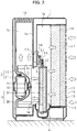
- a humidifier in accordance with an embodiment of the present invention includes, in a housing 1 having a shape of a rectangular box, (i) an air blowing fan 2, (ii) a humidifying filter unit 3, and (iii) a water tank 4.
- the inside of the housing 1 is divided, by a partition wall 1a, into (i) a suction chamber 1b located backwards and (ii) a discharge chamber 1c located frontwards.
- the suction chamber 1b is connected to the outside via multiple air inlets 15 which are opened in a back surface panel 14 of the housing 1.
- the discharge chamber 1c is connected to the outside via an air outlet 16 which is opened in a top plate of the housing 1.
- the suction chamber 1b and the discharge chamber 1c are connected to each other via an opening 1d provided at a bottom part of the partition wall 1a.
- the back surface panel 14 is removable.
- a deodorization filter 17 is formed by, for example, causing a nonwoven fabric to hold activated carbon in a dispersed manner.
- the deodorization filter 17 functions to adsorb and remove an odor component passing through the deodorization filter 17.
- the dust collecting filter 18 is, for example, a publicly-known HEPA (High Efficiency Particulate Air) filter, and functions to collect and remove fine dust passing through the dust collecting filter 18.
- HEPA High Efficiency Particulate Air
- the air blowing fan 2 includes an impeller 20 and a fan motor 21 which drives the impeller 20.
- the fan motor 21 is fixed outside the discharge chamber 1c.
- the impeller 20 is fixed to an output terminal of the fan motor 21 which protrudes into the discharge chamber 1c.
- the impeller 20 is provided so as to face the opening 1d at the bottom part of the partition wall 1a.
- the impeller 20 of the air blowing fan 2 is driven by the fan motor 21 so as to rotate. In a case where the impeller 20 rotates, outside air is, as indicated by outline arrows in Fig.
- the suction chamber 1b and the discharge chamber 1c inside the housing 1 thus form an air flow path in which airflow as described above is generated by an operation of the air blowing fan 2.
- the deodorization filter 17 and the dust collecting filter 18 are located at an upstream side of the air flow path described above. Outside air, which is introduced into the suction chamber 1b via the air inlets 15, (i) loses its odor component by passing through the deodorization filter 17 and (ii) becomes, by passing through the dust collecting filter 18, clean air from which dust has been removed. Then, the clean air is guided out via the air outlet 16 at the end of the discharge chamber 1c.
- the humidifier illustrated in the drawings serves also as an air purifier by including the deodorization filter 17 and the dust collecting filter 18.
- the humidifying filter unit 3 and the water tank 4 are provided between the dust collecting filter 18 and the air blowing fan 2 so as to humidify air which is flowing in the air flow path as described above.
- the water tank 4 is a dish-shaped container which is opened upwards.
- the water tank 4 is fitted into a guide 19 which is provided on a bottom plate of the housing 1, so that the water tank 4 is provided in the suction chamber 1b located in front of the dust collecting filter 18.
- the water tank 4 slides, along the guide 19, together with the humidifying filter unit 3 which is supported by the water tank 4 as described later. This allows the water tank 4 to be taken out from one side surface of the housing 1.
- a tank receiver 40 having a wide with is connected.
- a water feed tank 41 is to be removably attached.
- the water feed tank 41 is a rectangular parallelepiped tank having a faucet 42 at one end part thereof.
- the water feed tank 41 is to be mounted on the tank receiver 40 while the water feed tank 41 is upside down so that the faucet 42 faces downwards.
- the faucet 42 includes publicly-known overflow valve therein. While the water feed tank 41 is mounted on the tank receiver 40, the overflow valve is pushed up by a push-up protrusion 43 which is provided in the tank receiver 40 so as to correspond to the overflow valve (see Fig. 4 ). This causes the overflow valve to open. As a result, water contained in the water feed tank 41 is sent out into the water tank 4, so that water in the water tank 4 is stored at a certain level.
- the humidifying filter unit 3 is configured by containing and holding a humidifying filter 31 in a retention frame 30 having a form of a hollow disk.
- the retention frame 30 has a form of a disk that rotates around a horizontal axis, and contains and holds the humidifying filter 131 therein.
- the humidifying filter 31 is formed by removable two sheets that are each made of a material, such as a nonwoven fabric, which (i) is highly capable of containing water, (ii) has air permeability, and (iii) can be washed through rubbing.
- the humidifying filter 31 will be described in detail later.
- Fig. 4 is a perspective view illustrating a structure in which the humidifying filter unit 3 is supported. Note that Fig. 4 illustrates only the retention frame 30 instead of also illustrating the humidifying filter 31 in the retention frame 30. Note also that Fig. 4 illustrates only the tank receiver 40 at the one end part of the water tank 4 instead of also illustrating the water feed tank 41 mounted on the tank receiver 40.
- the retention frame 30 is mounted on two support rollers 6 provided in the water tank 4, so that the humidifying filter unit 3 is supported while oriented so as to stand vertically on the water tank 4.
- the support rollers 6 are each a roller that rotates around an axis that extend frontwards and backwards.
- the support rollers 6 are provided at respective sides so as to (i) spread longitudinally on a bottom surface of the water tank 4 and (ii) contact an outer circumferential surface of the retention frame 30 at respective positions.
- the humidifying filter unit 3 thus supported is capable of rotating around a center axis by rolling of the support rollers 6.
- the humidifying filter unit 3 thus supported can be easily removed, as illustrated in Fig. 2 , by (i) taking out the humidifying filter unit 3 together with the water tank 4 from the one side surface of the housing 1 and (ii) lifting the humidifying filter unit 3 upwards.
- the humidifying filter unit 3 by inserting part of the humidifying filter unit 3 into the water tank 4 so as to mount the humidifying filter unit 3 on the two support rollers 6, it is possible to easily support the humidifying filter unit 3 while the humidifying filter unit 3 is oriented as described above.
- the humidifying filter unit 3 is pushed into the housing 1 together with the water tank 4, it is possible to set the humidifying filter unit 3 at a certain position in the housing 1.
- the humidifying filter unit 3 is thus attached and removed so as to (i) maintain or replace a humidifying filter 31 contained in the retention frame 30 and (ii) clean the inside of the water tank 4.
- a ring gear 32 is provided so as to be integrated with the outer circumferential surface of the retention frame 30.
- the ring gear 32 has an appropriate width and has teeth which are provided (i) at a center part with respect to the width and (ii) along the entire outer circumferential surface.
- the ring gear 32 intermeshes with a transmission gear 51 of a drive unit 5 which is provided at an upper part of the retention frame 30.
- the drive unit 5 includes (i) a transmission gear 51 and a drive gear 52 which are attached to one surface of a base 50 and (ii) a driving motor 53 which is attached to the other surface of the base 50.
- the drive unit 5 is fixed at an appropriate position of the partition wall 1a in the housing 1 with use of a plurality of fixing screws (not illustrated) which run through the base 50.
- the drive gear 52 is fitted to an output shaft of the driving motor 53, so that rotation of the driving motor 53 is transmitted to the transmission gear 51 via the drive gear 52. This causes the transmission gear 51 to rotate.
- the humidifying filter unit 3 In a case where the humidifying filter unit 3 is set at the certain position described above, the transmission gear 51 of the drive unit 5 and the ring gear 32 of the retention frame 30 intermesh with each other as illustrated in Fig. 3 . Because of this intermeshing, the humidifying filter unit 3 is supported by the following three points along a circumference of the humidifying filter unit 3: the two support rollers 6 in the water tank 4; and the transmission gear 51 of the drive unit 5.
- the humidifying filter unit 3 thus supported is located in the suction chamber 1b so as to face (i) the front side of the dust collecting filter 18 and (ii) a back side of the air blowing fan 2.
- rotation of the drive gear 52 is transmitted to the retention frame 30 via the transmission gear 51 and the ring gear 32. This causes the humidifying filter unit 3 to rotate around the center axis while maintaining the position, as illustrated in Fig. 3 , at which the humidifying filter unit 3 is supported.
- the retention frame 30 has (i) a back surface (counter surface facing the dust collecting filter 18) and (ii) a front surface located opposite the back surface.
- a back surface counter surface facing the dust collecting filter 18
- a front surface located opposite the back surface.
- respective support rings 33 each having a circular shape is provided on a center part of the back surface and the front surface.
- a plurality of support ribs 34 (six support ribs in Fig. 4 ) for each of the support rings 33 are provided so as to the support ring 33 to an outer peripheral part.
- a stopping part 35 having a bow-like shape is provided so as to block a part in the vicinity of the outer peripheral part.
- a space in the retention frame 30, which space is to contain a humidifying filter 31, has a cross-section whose shape excludes the bow-like shape of the stopping part 35, that is, the cross section having a shape obtained by cutting out a bow-like part from a circular shape.
- the humidifying filter 31 contained in the space is held while being supported by the support rings 33 and the support ribs 34 from both the front side and the back side.
- water in the water tank 4 is stored at a certain level.
- a bottom part of the retention frame 30, which rotates as described above, is to be immersed in stored water in the water tank 4.
- the stored water enters the retention frame 30 via openings located at a front and a back of the retention frame 30. Then, the stored water is absorbed by the humidifying filter 31 which is contained and held in the retention frame 30.
- the air flowing as described above comes into contact with the humidifying filter 31 containing water, so as to become moist air containing vaporized moisture. Then, the moist air is guided out via the air outlet 16 at the end of the discharge chamber 1c, and then humidifies a room in which the humidifier is provided.
- a humidifying filter 31 will be described in detail below with reference to Fig. 1 .
- a humidifying filter 31 is to be provided in the humidifier, and, as illustrated in (a) of Fig. 1 , includes two sheet members 11 and 12.
- the sheet members 11 and 12 are each made of a material (e.g. rayon, PET), such as a nonwoven fabric, which (i) highly capable of containing water, (ii) has air permeability, and (iii) can be washed through rubbing.
- the sheet members 11 and 12 are also each configured to be removable.
- the sheet members 11 and 12 are attached and removed with use of attaching and removing members 13a and 13b which are provided at peripheries of the sheet members 11 and 12.
- the attaching and removing members 13a and 13b can be any members, provided that the attaching and removing members 13a and 13b are members, such as hook and loop fasteners (known in Japan as Magic Tape (registered trademark)) and snap fasteners, which can attach and remove the sheet members 11 and 12 with a single touch.
- views in (a) of Fig. 1 are plan views showing respective back surfaces of the sheet members 11 and 12. Therefore, the sheet members 11 and 12 are combined together with use of the attaching and removing members 13a and 13b while the respective back surfaces of the sheet members 11 and 12 are facing each other.
- the sheet members 11 and 12, which are combined together, can hardly stand by themselves because the materials are soft. Therefore, the sheet members 11 and 12 are supported in the retention frame 30 which serves as a support member.
- the sheet member 12 has a circular shape
- the sheet member 11 has a structure in which an end part 11a is cut out (see (a) of Fig. 1 ). Therefore, in a case where the two sheet members 11 and 12 are combined together, the sheet member 12 is partly exposed toward the sheet member 11 because of the end part 11a of the sheet member 11 (see (b) of Fig. 1 ).
- the humidifying filter 31 thus configured has a structure in which the two sheet members 11 and 12 overlap each other. However, since there is no overlapping of the sheet member 11 and the sheet member 12 at one end part 31a, it is possible to easily remove the sheet member 11 and the sheet member 12 from each other by inserting a finger at the one end part 31a.
- the sheet members 11 and 12 can have respective structures.
- the sheet members 11 and 12 can be easily separated and each washed through rubbing. This makes it possible to easily remove impurities stuck on the sheet members 11 and 12. That is, a user can easily maintain the humidifying filter 31.
- the sheet members 11 and 12 can be easily attached and removed with use of the attaching and removing members 13a and 13b such as hook and loop fasteners (known in Japan as Magic Tape) and snap fasteners, it is possible to sufficiently wash the front surfaces and the back surface of the sheet members 11 and 12.
- the attaching and removing members 13a and 13b such as hook and loop fasteners (known in Japan as Magic Tape) and snap fasteners
- the sheet members 11 and 12 are combined together, the sheet members 11 and 12 are supported by the retention frame 30 which serves as a support member. Therefore, neither one of the sheet members 11 and 12 needs much thickness or strength. That is, the sheet members 11 and 12 can each be made of a soft material which can be washed through rubbing. This makes it possible that through washing of the sheet members 11 and 12 through rubbing, impurities which are stuck on the humidifying filter 31 can be sufficiently removed only by washing with water.
- the sheet members 11 and 12 are removably provided with use of the attaching and removing members 13a and 13b, such as hook and loop fasteners (known in Japan as Magic Tape) or snap fasteners, which are provided at positions which are decided in advance. This makes it possible to easily decide positions of the sheet members 11 and 12 relative to each other.
- the attaching and removing members 13a and 13b such as hook and loop fasteners (known in Japan as Magic Tape) or snap fasteners, which are provided at positions which are decided in advance. This makes it possible to easily decide positions of the sheet members 11 and 12 relative to each other.
- the sheet members 11 and 12, which are included in the humidifying filter 31, can have respective water absorbing capacities.
- the sheet members 11 and 12 are made of identical materials, it is possible to cause the sheet members 11 and 12 to have respective water absorbing capacities by cutting out the end part 11a of the sheet member 11.
- the sheet members 11 and 12 can have identical shapes (surface areas), so that the neither of the sheet members 11 and 12 has a structure made by cutting out a part. In such a case, it is possible to cause the sheet members 11 and 12 to have respective water absorbing capacities by making the sheet members 11 and 12 with use of respective materials.
- the sheet members 11 and 12 have identical shapes (surface areas) and neither of the sheet members 11 and 12 has a structure made by cutting out a part, it is possible to cause the sheet members 11 and 12 to have respective water absorbing capacities by (i) making the sheet members 11 and 12 with use of identical materials and (ii) causing the sheet members 11 and 12 to differ in thickness.
- one of the sheets in the humidifying filter retains a water content even when the other one of the sheets has lost a water content. This makes it possible to avoid a considerable reduction in humidification performance.
- the sheet member 11 and the sheet member 12 are provided so as to respectively face downstream and upstream while the humidifying filter 31 is set in the humidifier, the sheet member 11 is to be lower in open area ratio than the sheet member 12.
- the "open area ratio" herein refers to fineness of a nonwoven fabric of which a sheet member is made. A smaller open area ratio and a larger open area ratio mean that the nonwoven fabric is fine and coarse, respectively.
- the humidifying filter 31 has not only a humidification function but also a dust collection function which is a function to (i) collect relatively large pieces of dust by the sheet member 12 at the upstream side and (ii) further collect, by the sheet member 11, dust which is contained in air having passed through the sheet member 12.
- the humidifying filter 31 is held by the retention frame 30 (support member) while the sheet members 11 and 12 are combined together.
- the retention frame 30 has a hollow disk-like structure so as to contain and hold the humidifying filter 31 therein. This makes it necessary to take the humidifying filter 31 out of the retention frame 30 in order to wash the humidifying filter.
- the sheet members 11 and 12 can be combined together at their peripheries by ultrasonic welding. In such a case, the sheet members 11 and 12 form a hollow. Furthermore, the sheet members 11 and 12 can be combined together at their center parts by ultrasonic welding. In a case where the sheet members 11 and 12 each have a structure made by cutting out a part at a cut-out part, the sheet members 11 and 12 can be combined together by ultrasonic welding at the cut-out parts.
- Embodiment 2 below will discuss a structure in which a humidifying filter 31 is not contained in a retention frame 30 with use of a structure of the humidifying filter 31 but is instead made to stand by itself through inserting a frame body into the humidifying filter 31.
- the humidifying filter 31 in accordance with Embodiment 2 includes a support member 60 which supports two sheet members 11 and 12 while the sheet members 11 and 12 are combined together. Specifically, as illustrated in (b) of Fig. 5 , the two sheet members 11 and 12 cover the support member 60 while the sheet members 11 and 12 are combined together.
- the support member 60 has a three-dimensional frame body structure having an inner part 60a which is structured to be hollow. This makes it possible to enlarge a surface area of the humidifying filter 31 by causing the humidifying filter 31 to cover the support member 60. It is therefore possible to increase a humidifying effect.
- the humidifying filter 31 is configured so that the support member 60 is covered, it is possible to easily remove the humidifying filter 31 from the support member 60.
- the sheet member 11 and the sheet member 12 are provided so as to respectively face downstream and upstream while the humidifying filter 31 is set in a humidifier, the sheet member 11 preferably has an open area ratio lower than that of the sheet member 12.
- the structure of the support member 60 is not limited to that illustrated in (a) of Fig. 5 .
- the support member 60 can have any shape, provided that the shape allows a three-dimensional structure of the humidifying filter 31 to be maintained while the humidifying filter 31 covers the support member 60.
- the inner part 60a of the support member 60 is preferably structured to be hollow. This allows air to pass through the inner part 60a, and therefore allows water contained in the humidifying filter 31, which covers the support member 60, to be vaporized.
- the inner part 60a is not necessarily structured to be hollow.
- the inner part 60a of the support member 60 is structured to be hollow and (ii) a rotation center 31b of the humidifying filter 31 covering the support member 60 is an opening. With use of this opening, the humidifying filter 31 rotates along with the support member 60.
- a humidifying filter 131 used in Embodiment 3 is obtained by folding sheet members so that the sheet members are stacked so as to form an accordion-like shape (see Fig. 6 ).
- a humidifier has a structure identical to the structures described in Embodiments 1 and 2 except that the humidifying filter 131 is used.
- the humidifying filter 131 is obtained by folding the sheet members so that the sheet members are stacked so as to form an accordion-like shape, a plurality of crease lines 131a are formed as illustrated in Fig. 6 .
- the humidifying filter 131 water is absorbed along the crease lines 131a.
- This causes a water absorbing capacity to vary, depending on an angle between (i) a direction in which the crease lines 131a extend and (ii) a direction extending parallel to a surface of stored water in a water tank 4.
- the angle which is made between (i) the direction in which the crease lines 131a extend and (ii) the direction extending parallel to the surface of the stored water in the water tank 4, is 90° in (a) of Fig. 6 , 180° in (b) of Fig. 6 , and 45° in (c) of Fig. 6 .
- FIG. 7 is a graph showing changes in humidification amount over time, which changes occur in respective cases where rotation of the humidifying filter 131 is stopped while the angles shown in Fig. 6 are made.
- a volume of air blowing against the humidifying filter 131 is constantly 6.8 cmm.
- the graph of Fig. 7 indicates that the humidification amount is (i) largest in the case where the angle, which is made between the direction in which the crease lines 131a extend and the direction extending parallel to the surface of the stored water in the water tank 4, is 90° and (ii) smallest in the case where the angle is 180°.
- a humidification amount can be controlled by adjusting an angle between (i) a direction in which the crease lines 131a of the humidifying filter 131 extend and (ii) a direction which extends parallel to a surface of stored water in the water tank 4 (such an angle is hereinafter referred to as "humidity control angle").
- Fig. 8 is a graph showing humidity control in Embodiment 3.
- Fig. 9 is a graph showing conventional humidity control for the purpose of comparison with Fig. 8 .
- the graph of Fig. 9 shows that large fluctuations occur with respect to a target humidity of a room, and therefore indicates that a large degree of unnecessary humidification is carried out.
- a volume of air is assumed to be constant.
- rotation of a humidifying filter is stopped.
- humidification does not immediately stop even after the rotation is stopped.
- the rotation of the humidifying filter is started when the humidity is lower than the target humidity.
- it takes time for the humidifying filter to contain water humidification requires time. According to the conventional humidity control, humidity thus cannot be controlled properly because, even if a target humidity is set, there are times when the humidity is above and below the target humidity.
- the graph of Fig. 8 indicates that humidity is controlled such that any fluctuation hardly occurs with respect to a target humidity of a room.
- a volume of air is assumed to be constant.
- rotation of a humidification motor for rotating the humidifying filter 131 can be kept at minimum. This allows noise, which is caused by driving of the humidification motor, to be reduced.
- a humidification amount can be controlled merely by adjusting a rotation angle of the humidifying filter 131, a volume of air to blow against the humidifying filter 131 can be constant. Therefore, unlike the conventional humidity control, it is unnecessary to increase or decrease the volume of air more than necessary to adjust the humidification amount. This allows noise, which is caused by an air blowing fan, to be reduced. It is therefore possible to considerably reduce, in comparison with the case of a conventional humidifier, noise which is generated when the humidifier is carrying out a humidification operation.
- Fig. 10 is a view illustrating a structure for supporting a humidifying filter unit for achieving humidity control by the humidifier in accordance with Embodiment 3.
- the humidifier includes a position detector 7 for detecting that the humidifying filter 131 is at certain rotation positions (rotation positions illustrated in (a) through (c) of Fig. 6 ).
- the position detector 7 is configured so that a sensor, which is provided at the stopping part 35 of the retention frame 30 so as to be away from a center by an appropriate distance toward a part of a circumference, outputs a detection signal when the sensor is located at a bottommost position during the rotation of the retention frame 30.
- the position detector 7 can be configured by a combination of, for example, (i) a magnet serving as the sensor and (ii) a proximity switch.
- the detection signal from the position detector 7 is supplied to a control section (humidity controlling section) 8 which controls an operation.
- the control section 8 shown by a block in Fig. 10 is a computer which includes CPU, ROM, and RAM.
- An operation of the control section 8 is to control driving of a drive unit 5 by supplying the drive unit 5 with an operation command in accordance with an operation of a user.
- the humidifying filter unit 3 rotates. This, as described above, causes stored water in the water tank 4 to (i) be absorbed by the humidifying filter 131 of the retention frame 30 and (ii) lifted by the rotation of the retention frame 30, so as to permeate the entire humidifying filter 131. Therefore, the air flowing as described above comes into contact with the humidifying filter 131 containing water, so as to become moist air containing vaporized moisture. Then, the moist air is guided out the humidifier, and then humidifies a room in which the humidifier is provided.
- a desired humidification amount can be obtained by stopping the rotation of the humidifying filter unit 3 such that an angle, which is made between (i) a direction in which the crease lines 131a of the humidifying filter 131 extends and (ii) a direction extending parallel to a water surface L of stored water in the water tank, becomes any of the angles shown in (a) through (c) of Fig. 6 .
- this rotation angle of the humidifying filter unit 3 it is possible to control humidity in a room in which the humidifier is provided.
- the rotation angle can be controlled not only by the method in which the position detector 7 is used, but also by (i) a period of time in which the rotation is made or (ii) any other method.
- the control section 8 refers to a detection signal from the position detector 7 so as to stop driving of the drive unit 5 with a timing with which the detection signal is supplied. This causes the humidifying filter unit 3 to stop in the rotation position illustrated in Fig. 10 .
- the sensor which is provided at the stopping part 35 of the retention frame 30 as described above, is located at a bottommost position on the circumference along which the retention frame 30 rotates. As illustrated in Fig.
- the humidifying filter unit 3 stops while being oriented so that a string-like portion of the stopping part 35 having the bow-like shape is (i) mostly above the water surface (internal water level L) of the stored water in the water tank 4 and (ii) sloped with respect to the water surface.
- the humidifying filter 131 contained in the retention frame 30 has the crease lines extending substantially parallel to the string-like portion of the stopping part 35 having the bow-like shape. Therefore, when the humidifying filter unit 3 stops, the crease lines 131a, which are the crease lines of the humidifying filter 131, are also sloped with respect to the surface of the stored water, that is, with respect to a horizontal direction.
- Fig. 10 shows that the string-like portion of the stopping part 35 is partly below the surface of the stored water when the retention frame 30 stops
- the humidifying filter 131 absorbs no water at all after the rotation is stopped. This configuration is therefore more effective.
- Embodiment 4 below will discuss a configuration in which a humidifying filter is not in contact with stored water while a humidifier is not carrying out a humidification operation.
- Fig. 11 is a set of views each schematically illustrating a configuration of a humidifying filter.
- (a) of Fig. 11 illustrates the humidifying filter 131 used in Embodiment 3.
- (b) of Fig. 11 illustrates a humidifying filter 231 in accordance with Embodiment 4.
- a center of a circle is a rotation center around which the humidifying filter 131 rotates.
- a rotation center around which the humidifying filter 231 rotates is a position which is shifted from a center of a circle. The rotation center is located so that when the humidifying filter 231 stops rotating, (i) a portion of the humidifying filter 231, at which portion a distance from the rotation center to a circumference of the humidifying filter 231 is the shortest, faces a surface of stored water and (ii) the humidifying filter 231 is not immersed in the stored water.
- the humidifying filter 131 can be prevented from being immersed in stored water, by configuring the humidifying filter 131 so that, as illustrated in Fig. 10 of Embodiment 3, the string-like portion of the stopping part 35 is partly below the surface of the stored water when the retention frame 30 stops rotating.
- the humidifying filter 131 becomes immersed in the stored water. In such a case, a part of the humidifying filter 131 is to be cut out, so that the humidifying filter 131 is not immersed in the stored water after the humidifying filter 131 stops rotating.
- the humidifying filter 231 can be prevented from being immersed in the stored water, by causing the humidifying filter 231 to stop rotating so that a portion of the humidifying filter 231, at which portion the distance from the rotation center of the humidifying filter 231 to the end surface is the shortest, is located at a bottom.
- the rotation is made by causing the ring gear 32, which is provided at the outer circumferential surface of the retention frame 30, to mesh with the drive gear 52 of the drive unit 5 (see Fig. 10 ).
- the rotation is made by (i) providing a ring gear 132 around the rotation center instead of providing the ring gear 132 at an outer circumferential surface of a retention frame 30 and (ii) causing the ring gear 132 to mesh with the drive gear 52 of the drive unit 5 (see Fig. 10 ).
- the ring gear 132 at the outer circumferential surface of the retention frame 30 of the humidifying filter 231 illustrated in (b) of Fig. 11 .
- the drive unit 5 illustrated in Fig. 10 follows the rotation of the humidifying filter 231 by vertically moving.
- the rotation center of the humidifying filter 231 is merely shifted from the center of the circle as described above without cutting out a part of the humidifying filter 231. This prevents a decrease in surface area, which decrease is caused by cutting out a part of the humidifying filter 231. A reduction in humidification performance is therefore prevented.
- Embodiment 4 discussed an example in which the rotation center of the humidifying filter 231, which has a circular shape, is shifted as illustrated in (b) of Fig. 11 .
- the humidifying filter can have an ellipsoidal shape instead of the circular shape.
- a humidifying filter in accordance with Aspect 1 of the present invention is a humidifying filter 31 to be provided in a humidifier, including: two sheet members 11 and 12 which are removably combined together; and a support member (retention frame 30, support member 60) which supports the two sheet members 11 and 12 while the two sheet members 11 and 12 are combined together.
- the humidifying filter since the humidifying filter has a structure in which the two sheet members are removably combined together, it is difficult to allow the sheet members to stand by themselves unless the sheet members each have a certain degree of thickness and strength.
- the humidifying filter since the humidifying filter includes the support member, neither one of the sheet members needs much thickness or strength. That is, the sheet members can each be made of a soft material which can be washed through rubbing. This makes it possible that through washing of the sheet members through rubbing, impurities which are stuck on the humidifying filter can be sufficiently removed only by washing with water.
- the humidifying filter of Aspect 1 can be arranged so that the two sheet members 11 and 12 cover the support member 60 while the two sheet members 11 and 12 are combined together.
- the humidifying filter covers the support member. This allows the humidifying filter to be easily removed from the support member 60.
- the humidifying filter of Aspect 2 is preferably arranged so that the support member 60 has a three-dimensional frame body structure.
- the humidifying filter of any one of Aspects 1 through 3 is preferably arranged so that an end part 11a of a sheet member 11, which is at least one of the two sheet members 11 and 12, is cut out.
- a humidifier in accordance with Aspect 5 of the present invention is a humidifier including: a humidifying filter 131 which is obtained by folding sheet members so that the sheet members are stacked so as to form an accordion-like shape; a retention frame 30 which (i) contains and holds the humidifying filter 131 therein and (ii) has a form of a disk that rotates around a horizontal axis; a water tank 4 in which the retention frame 30 is provided so that a bottom part of the retention frame 30 is immersed in stored water; and a humidity controlling section (control section 8) which controls a humidification amount by adjusting an angle between (i) a direction in which crease lines 131a of the humidifying filter 131 extend and (ii) a direction which extends parallel to a surface L of the stored water in the water tank 4, the humidifier being configured so that (i) air, which is passing from one surface of the retention frame 30 to the other surface, comes into contact with the humidifying filter 131 which is rotating along with the retention frame 30 while the humidifying filter
- the humidifying filter includes the sheet members which are folded so that the sheet members are stacked so as to form an accordion-like shape. Therefore, a water absorbing capacity of the humidifying filter varies, depending on an angle between (i) a direction in which crease lines of the humidifying filter extend and (ii) a direction extending parallel to a surface of the stored water. To take advantage of this mechanism, it is possible to control the humidification amount by causing the humidity controlling section to adjust the angle.
- a humidification amount can be easily controlled by adjusting a rotation angle of the humidifying filter.
- the humidifier of Aspect 5 can be arranged so that the humidity controlling section (control section 8) controls the humidification amount while a volume of the air passing is constant.
- the humidifier of Aspect 5 or 6 can be arranged so that in a case where the humidifying filter 231 has a shape of a circle, a rotation center of the humidifying filter 231 is shifted from a center of the circle.
- the humidifier of Aspect 7 can be arranged so that the rotation center is located so that when the humidifying filter 231 stops rotating, (i) a portion of the humidifying filter 231, at which portion a distance from the rotation center to a circumference of the humidifying filter 231 is the shortest, faces a surface of stored water and (ii) the humidifying filter 231 is not immersed in the stored water.
- the present invention is not limited to the embodiments, but can be altered by a skilled person in the art within the scope of the claims.
- the present invention also encompasses, in its technical scope, any embodiment derived by combining technical means disclosed in differing embodiments. Further, it is possible to form a new technical feature by combining the technical means disclosed in the respective embodiments.
Landscapes
- Engineering & Computer Science (AREA)
- Chemical & Material Sciences (AREA)
- Combustion & Propulsion (AREA)
- Mechanical Engineering (AREA)
- General Engineering & Computer Science (AREA)
- Air Humidification (AREA)
- Filtering Of Dispersed Particles In Gases (AREA)
Abstract
Description
- The present invention relates to a humidifier and to a humidifying filter for use in a humidifier.
- In a case where a typical home-use humidifying air purifier is used, impurities, such as minerals contained in water for humidification, stick to a humidifying filter. This causes odor to be generated, and leads to a reduction in humidification amount. Accordingly, it is necessary to periodically replace the humidifying filter in its entirety, and therefore costs for replacement of humidifying filters are incurred.
-
Patent Literature 1 discloses a technique for reducing the cost for replacement of a humidifying filter by, instead of replacing a humidifying filter in its entirety, replacing only part of the humidifying filter which part has impurities stuck thereon. - There are also proposals for washing off, with water, impurities stuck on a humidifying filter, instead of replacing the humidifying filter.
- Japanese Patent Application Publication Tokukai No.
2009-68732 (Publication date: April 2, 2009 - A typical humidifying filter is formed by folding a nonwoven fabric into an accordion-like shape because the humidifying filter needs a certain degree of hardness for avoiding deformation which would cause (i) deterioration and (ii) an effect on a humidification amount. Therefore, the humidifying filter cannot be washed through rubbing. This unfortunately prevents impurities, which are stuck on the humidifying filter, from being sufficiently removed even through washing with water.
- The present invention has been made in view of the problem, and an object of the present invention is to achieve (i) a humidifying filter that allows impurities, which are stuck on the humidifying filter, to be sufficiently removed by washing with water and (ii) a humidifier including such a humidifying filter.
- In order to attain the object, a humidifying filter in accordance with an aspect of the present invention is a humidifying filter to be provided in a humidifier, including: two sheet members which are removably combined together; and a support member which supports the two sheet members while the two sheet members are combined together.
- With an aspect of the present invention, it is advantageously possible that in a case where a sheet member is removed from a support member, impurities stuck on a humidifying filter are sufficiently removed by washing with water.
-
-
Fig. 1 is a view schematically illustrating a configuration of a humidifying filter in accordance withEmbodiment 1 of the present invention. -
Fig. 2 is a perspective view illustrating an appearance of a humidifier including the humidifying filter illustrated inFig. 1 . -
Fig. 3 is a cross-sectional view schematically illustrating a configuration of the humidifier illustrated inFig. 2 . -
Fig. 4 is a perspective view illustrating a structure in which a humidifying filter unit in the humidifier illustrated inFig. 2 is supported. -
Fig. 5 is a set of perspective views illustrating a support frame which supports a humidifying filter in accordance with Embodiment 2 of the present invention. (a) ofFig. 5 is a perspective view illustrating the support frame before the humidifying filter is mounted. (b) ofFig. 5 is a perspective view illustrating the support frame after the humidifying filter is mounted. -
Fig. 6 is a view schematically illustrating a configuration of a humidifier in accordance withEmbodiment 3 of the present invention for describing humidity control by the humidifier. -
Fig. 7 is a graph showing relationships between a rotation angle of the humidifying filter and a humidification amount. -
Fig. 8 is a graph showing a relationship between time and a target humidity as a result of humidity control in accordance with an embodiment of the present invention. -
Fig. 9 is a graph showing a relationship between time and a target humidity as a result of humidity control in accordance with a comparative example. -
Fig. 10 is a main-part cutaway front view illustrating a structure for supporting a humidifying filter unit for controlling rotation of the humidifying filter. -
Fig. 11 is a view schematically illustrating a configuration of a humidifying filter in accordance withEmbodiment 4 of the present invention. - The following description will discuss embodiments of the present invention in detail.
- As illustrated in
Fig. 3 , a humidifier in accordance with an embodiment of the present invention includes, in ahousing 1 having a shape of a rectangular box, (i) an air blowing fan 2, (ii) ahumidifying filter unit 3, and (iii) awater tank 4. The inside of thehousing 1 is divided, by apartition wall 1a, into (i) asuction chamber 1b located backwards and (ii) adischarge chamber 1c located frontwards. Thesuction chamber 1b is connected to the outside viamultiple air inlets 15 which are opened in aback surface panel 14 of thehousing 1. Thedischarge chamber 1c is connected to the outside via anair outlet 16 which is opened in a top plate of thehousing 1. Thesuction chamber 1b and thedischarge chamber 1c are connected to each other via an opening 1d provided at a bottom part of thepartition wall 1a. - As illustrated in
Fig. 1 , theback surface panel 14 is removable. At a front side of theback surface panel 14, there are provided adeodorization filter 17 and adust collecting filter 18 which are stacked together. Thedeodorization filter 17 is formed by, for example, causing a nonwoven fabric to hold activated carbon in a dispersed manner. The deodorization filter 17 functions to adsorb and remove an odor component passing through thedeodorization filter 17. Thedust collecting filter 18 is, for example, a publicly-known HEPA (High Efficiency Particulate Air) filter, and functions to collect and remove fine dust passing through thedust collecting filter 18. Thedeodorization filter 17 and thedust collecting filter 18 are fitted into a filter chamber provided at the front side of theback surface panel 14. - The air blowing fan 2 includes an
impeller 20 and a fan motor 21 which drives theimpeller 20. The fan motor 21 is fixed outside thedischarge chamber 1c. Theimpeller 20 is fixed to an output terminal of the fan motor 21 which protrudes into thedischarge chamber 1c. Theimpeller 20 is provided so as to face the opening 1d at the bottom part of thepartition wall 1a. Theimpeller 20 of the air blowing fan 2 is driven by the fan motor 21 so as to rotate. In a case where theimpeller 20 rotates, outside air is, as indicated by outline arrows inFig. 3 , (i) introduced into thesuction chamber 1b via theair inlets 15 which are provided in theback surface panel 14, (ii) allowed to flow frontwards in thesuction chamber 1b, (iii) sucked into theimpeller 20 via the opening 1d at the bottom part of thepartition wall 1a, (iv) allowed to turn upwards, (v) led out into thedischarge chamber 1c, and (vi) guided out via theair outlet 16 at an end of thedischarge chamber 1c. - The
suction chamber 1b and thedischarge chamber 1c inside thehousing 1 thus form an air flow path in which airflow as described above is generated by an operation of the air blowing fan 2. Thedeodorization filter 17 and thedust collecting filter 18 are located at an upstream side of the air flow path described above. Outside air, which is introduced into thesuction chamber 1b via theair inlets 15, (i) loses its odor component by passing through thedeodorization filter 17 and (ii) becomes, by passing through thedust collecting filter 18, clean air from which dust has been removed. Then, the clean air is guided out via theair outlet 16 at the end of thedischarge chamber 1c. The humidifier illustrated in the drawings serves also as an air purifier by including thedeodorization filter 17 and thedust collecting filter 18. - The humidifying
filter unit 3 and thewater tank 4 are provided between thedust collecting filter 18 and the air blowing fan 2 so as to humidify air which is flowing in the air flow path as described above. - The
water tank 4 is a dish-shaped container which is opened upwards. Thewater tank 4 is fitted into a guide 19 which is provided on a bottom plate of thehousing 1, so that thewater tank 4 is provided in thesuction chamber 1b located in front of thedust collecting filter 18. As illustrated inFig. 2 , thewater tank 4 slides, along the guide 19, together with the humidifyingfilter unit 3 which is supported by thewater tank 4 as described later. This allows thewater tank 4 to be taken out from one side surface of thehousing 1. To an end part on a side where thewater tank 4 is taken out, atank receiver 40 having a wide with is connected. To thetank receiver 40, awater feed tank 41 is to be removably attached. - The
water feed tank 41 is a rectangular parallelepiped tank having afaucet 42 at one end part thereof. Thewater feed tank 41 is to be mounted on thetank receiver 40 while thewater feed tank 41 is upside down so that thefaucet 42 faces downwards. Thefaucet 42 includes publicly-known overflow valve therein. While thewater feed tank 41 is mounted on thetank receiver 40, the overflow valve is pushed up by a push-upprotrusion 43 which is provided in thetank receiver 40 so as to correspond to the overflow valve (seeFig. 4 ). This causes the overflow valve to open. As a result, water contained in thewater feed tank 41 is sent out into thewater tank 4, so that water in thewater tank 4 is stored at a certain level. - The
humidifying filter unit 3 is configured by containing and holding ahumidifying filter 31 in aretention frame 30 having a form of a hollow disk. Specifically, theretention frame 30 has a form of a disk that rotates around a horizontal axis, and contains and holds thehumidifying filter 131 therein. Thehumidifying filter 31 is formed by removable two sheets that are each made of a material, such as a nonwoven fabric, which (i) is highly capable of containing water, (ii) has air permeability, and (iii) can be washed through rubbing. Thehumidifying filter 31 will be described in detail later. -
Fig. 4 is a perspective view illustrating a structure in which thehumidifying filter unit 3 is supported. Note thatFig. 4 illustrates only theretention frame 30 instead of also illustrating thehumidifying filter 31 in theretention frame 30. Note also thatFig. 4 illustrates only thetank receiver 40 at the one end part of thewater tank 4 instead of also illustrating thewater feed tank 41 mounted on thetank receiver 40. - As illustrated in
Fig. 4 , theretention frame 30 is mounted on twosupport rollers 6 provided in thewater tank 4, so that thehumidifying filter unit 3 is supported while oriented so as to stand vertically on thewater tank 4. Thesupport rollers 6 are each a roller that rotates around an axis that extend frontwards and backwards. Thesupport rollers 6 are provided at respective sides so as to (i) spread longitudinally on a bottom surface of thewater tank 4 and (ii) contact an outer circumferential surface of theretention frame 30 at respective positions. Thehumidifying filter unit 3 thus supported is capable of rotating around a center axis by rolling of thesupport rollers 6. - The
humidifying filter unit 3 thus supported can be easily removed, as illustrated inFig. 2 , by (i) taking out thehumidifying filter unit 3 together with thewater tank 4 from the one side surface of thehousing 1 and (ii) lifting thehumidifying filter unit 3 upwards. On the other hand, by inserting part of thehumidifying filter unit 3 into thewater tank 4 so as to mount thehumidifying filter unit 3 on the twosupport rollers 6, it is possible to easily support thehumidifying filter unit 3 while thehumidifying filter unit 3 is oriented as described above. In so doing, in a case where thehumidifying filter unit 3 is pushed into thehousing 1 together with thewater tank 4, it is possible to set thehumidifying filter unit 3 at a certain position in thehousing 1. Thehumidifying filter unit 3 is thus attached and removed so as to (i) maintain or replace ahumidifying filter 31 contained in theretention frame 30 and (ii) clean the inside of thewater tank 4. - As illustrated in
Fig. 4 , aring gear 32 is provided so as to be integrated with the outer circumferential surface of theretention frame 30. Thering gear 32 has an appropriate width and has teeth which are provided (i) at a center part with respect to the width and (ii) along the entire outer circumferential surface. As illustrated inFig. 3 , thering gear 32 intermeshes with atransmission gear 51 of adrive unit 5 which is provided at an upper part of theretention frame 30. - The
drive unit 5 includes (i) atransmission gear 51 and adrive gear 52 which are attached to one surface of abase 50 and (ii) a drivingmotor 53 which is attached to the other surface of thebase 50. Thedrive unit 5 is fixed at an appropriate position of thepartition wall 1a in thehousing 1 with use of a plurality of fixing screws (not illustrated) which run through thebase 50. Thedrive gear 52 is fitted to an output shaft of the drivingmotor 53, so that rotation of the drivingmotor 53 is transmitted to thetransmission gear 51 via thedrive gear 52. This causes thetransmission gear 51 to rotate. - In a case where the
humidifying filter unit 3 is set at the certain position described above, thetransmission gear 51 of thedrive unit 5 and thering gear 32 of theretention frame 30 intermesh with each other as illustrated inFig. 3 . Because of this intermeshing, thehumidifying filter unit 3 is supported by the following three points along a circumference of the humidifying filter unit 3: the twosupport rollers 6 in thewater tank 4; and thetransmission gear 51 of thedrive unit 5. - As illustrated in
Fig. 3 , thehumidifying filter unit 3 thus supported is located in thesuction chamber 1b so as to face (i) the front side of thedust collecting filter 18 and (ii) a back side of the air blowing fan 2. In a case where the drivingmotor 53 drives, rotation of thedrive gear 52 is transmitted to theretention frame 30 via thetransmission gear 51 and thering gear 32. This causes thehumidifying filter unit 3 to rotate around the center axis while maintaining the position, as illustrated inFig. 3 , at which thehumidifying filter unit 3 is supported. - As illustrated in
Fig. 4 , theretention frame 30 has (i) a back surface (counter surface facing the dust collecting filter 18) and (ii) a front surface located opposite the back surface. On a center part of the back surface and the front surface, respective support rings 33 each having a circular shape is provided. A plurality of support ribs 34 (six support ribs inFig. 4 ) for each of the support rings 33 are provided so as to thesupport ring 33 to an outer peripheral part. Furthermore, a stoppingpart 35 having a bow-like shape is provided so as to block a part in the vicinity of the outer peripheral part. - A space in the
retention frame 30, which space is to contain ahumidifying filter 31, has a cross-section whose shape excludes the bow-like shape of the stoppingpart 35, that is, the cross section having a shape obtained by cutting out a bow-like part from a circular shape. Thehumidifying filter 31 contained in the space is held while being supported by the support rings 33 and thesupport ribs 34 from both the front side and the back side. - As described above, water in the
water tank 4 is stored at a certain level. A bottom part of theretention frame 30, which rotates as described above, is to be immersed in stored water in thewater tank 4. The stored water enters theretention frame 30 via openings located at a front and a back of theretention frame 30. Then, the stored water is absorbed by thehumidifying filter 31 which is contained and held in theretention frame 30. - In a case where the air blowing fan 2 is driven in the humidifier thus configured, airflow through the
suction chamber 1b and thedischarge chamber 1c in thehousing 1 is generated as described above. This causes air to (i) be introduced into theretention frame 30 of thehumidifying filter unit 3 via the opening at the front surface of theretention frame 30, (ii) pass through thehumidifying filter 31, and then (iii) be guided out via the opening at the back surface. In a case where thedrive unit 5 is driven, thehumidifying filter unit 3 rotates. This, as described above, causes the stored water in thewater tank 4 to (i) be absorbed by thehumidifying filter 31 of theretention frame 30 and (ii) lifted by the rotation of theretention frame 30, so as to permeate theentire humidifying filter 31. Therefore, the air flowing as described above comes into contact with thehumidifying filter 31 containing water, so as to become moist air containing vaporized moisture. Then, the moist air is guided out via theair outlet 16 at the end of thedischarge chamber 1c, and then humidifies a room in which the humidifier is provided. - A
humidifying filter 31 will be described in detail below with reference toFig. 1 . - A
humidifying filter 31 is to be provided in the humidifier, and, as illustrated in (a) ofFig. 1 , includes twosheet members sheet members sheet members sheet members members sheet members members members sheet members Fig. 1 are plan views showing respective back surfaces of thesheet members sheet members members sheet members sheet members sheet members retention frame 30 which serves as a support member. - While the
sheet member 12 has a circular shape, thesheet member 11 has a structure in which anend part 11a is cut out (see (a) ofFig. 1 ). Therefore, in a case where the twosheet members sheet member 12 is partly exposed toward thesheet member 11 because of theend part 11a of the sheet member 11 (see (b) ofFig. 1 ). - The
humidifying filter 31 thus configured has a structure in which the twosheet members sheet member 11 and thesheet member 12 at oneend part 31a, it is possible to easily remove thesheet member 11 and thesheet member 12 from each other by inserting a finger at the oneend part 31a. - Alternatively, the
sheet members - After the
humidifying filter 31 is removed from the device, thesheet members sheet members humidifying filter 31. - In particular, since the
sheet members members sheet members - However, while the
sheet members sheet members retention frame 30 which serves as a support member. Therefore, neither one of thesheet members sheet members sheet members humidifying filter 31 can be sufficiently removed only by washing with water. - Since the
end part 11a of thesheet member 11 is cut out, it is possible to easily judge, when thesheet members humidifying filter 31 is to face upwind or downwind. - Furthermore, the
sheet members members sheet members - Therefore, in a case where the
sheet members sheet members sheet members - The
sheet members humidifying filter 31, can have respective water absorbing capacities. In a case where thesheet members sheet members end part 11a of thesheet member 11. - Alternatively, the
sheet members sheet members sheet members sheet members - In a case where the
sheet members sheet members sheet members sheet members sheet members - In a case where the
sheet members - In a case where the
sheet member 11 and thesheet member 12 are provided so as to respectively face downstream and upstream while thehumidifying filter 31 is set in the humidifier, thesheet member 11 is to be lower in open area ratio than thesheet member 12. The "open area ratio" herein refers to fineness of a nonwoven fabric of which a sheet member is made. A smaller open area ratio and a larger open area ratio mean that the nonwoven fabric is fine and coarse, respectively. Therefore, in a case where thesheet members humidifying filter 31 has not only a humidification function but also a dust collection function which is a function to (i) collect relatively large pieces of dust by thesheet member 12 at the upstream side and (ii) further collect, by thesheet member 11, dust which is contained in air having passed through thesheet member 12. - The
humidifying filter 31 is held by the retention frame 30 (support member) while thesheet members retention frame 30 has a hollow disk-like structure so as to contain and hold thehumidifying filter 31 therein. This makes it necessary to take thehumidifying filter 31 out of theretention frame 30 in order to wash the humidifying filter. - Alternatively, the
sheet members sheet members sheet members sheet members sheet members - Embodiment 2 below will discuss a structure in which a
humidifying filter 31 is not contained in aretention frame 30 with use of a structure of thehumidifying filter 31 but is instead made to stand by itself through inserting a frame body into thehumidifying filter 31. - The following description will discuss another embodiment of the present invention. For convenience, members which are identical in function to the members described in
Embodiment 1 are given respective identical reference signs, and descriptions of those members are omitted. - As illustrated in (a) of
Fig. 5 , thehumidifying filter 31 in accordance with Embodiment 2 includes asupport member 60 which supports twosheet members sheet members Fig. 5 , the twosheet members support member 60 while thesheet members - The
support member 60 has a three-dimensional frame body structure having aninner part 60a which is structured to be hollow. This makes it possible to enlarge a surface area of thehumidifying filter 31 by causing thehumidifying filter 31 to cover thesupport member 60. It is therefore possible to increase a humidifying effect. - In addition, since the
humidifying filter 31 is configured so that thesupport member 60 is covered, it is possible to easily remove thehumidifying filter 31 from thesupport member 60. - In a case where the
sheet member 11 and thesheet member 12 are provided so as to respectively face downstream and upstream while thehumidifying filter 31 is set in a humidifier, thesheet member 11 preferably has an open area ratio lower than that of thesheet member 12. - The structure of the
support member 60 is not limited to that illustrated in (a) ofFig. 5 . Thesupport member 60 can have any shape, provided that the shape allows a three-dimensional structure of thehumidifying filter 31 to be maintained while thehumidifying filter 31 covers thesupport member 60. - The
inner part 60a of thesupport member 60 is preferably structured to be hollow. This allows air to pass through theinner part 60a, and therefore allows water contained in thehumidifying filter 31, which covers thesupport member 60, to be vaporized. However, theinner part 60a is not necessarily structured to be hollow. - Alternatively, it is possible that (i) the
inner part 60a of thesupport member 60 is structured to be hollow and (ii) arotation center 31b of thehumidifying filter 31 covering thesupport member 60 is an opening. With use of this opening, thehumidifying filter 31 rotates along with thesupport member 60. - The following description will discuss an embodiment of the present invention. For convenience, members which are identical in function to the members described in the previous embodiments are given respective identical reference signs, and descriptions of those members are omitted.
- Unlike the
humidifying filter 31 described inEmbodiments 1 and 2, ahumidifying filter 131 used inEmbodiment 3 is obtained by folding sheet members so that the sheet members are stacked so as to form an accordion-like shape (seeFig. 6 ). - In
Embodiment 3, a humidifier has a structure identical to the structures described inEmbodiments 1 and 2 except that thehumidifying filter 131 is used. - Since the
humidifying filter 131 is obtained by folding the sheet members so that the sheet members are stacked so as to form an accordion-like shape, a plurality ofcrease lines 131a are formed as illustrated inFig. 6 . - According to the
humidifying filter 131, water is absorbed along thecrease lines 131a. This causes a water absorbing capacity to vary, depending on an angle between (i) a direction in which thecrease lines 131a extend and (ii) a direction extending parallel to a surface of stored water in awater tank 4. For example, the angle, which is made between (i) the direction in which thecrease lines 131a extend and (ii) the direction extending parallel to the surface of the stored water in thewater tank 4, is 90° in (a) ofFig. 6 , 180° in (b) ofFig. 6 , and 45° in (c) ofFig. 6 .Fig. 7 is a graph showing changes in humidification amount over time, which changes occur in respective cases where rotation of thehumidifying filter 131 is stopped while the angles shown inFig. 6 are made. InEmbodiment 3, a volume of air blowing against thehumidifying filter 131 is constantly 6.8 cmm. - The graph of
Fig. 7 indicates that the humidification amount is (i) largest in the case where the angle, which is made between the direction in which thecrease lines 131a extend and the direction extending parallel to the surface of the stored water in thewater tank 4, is 90° and (ii) smallest in the case where the angle is 180°. - It is therefore understood that a humidification amount can be controlled by adjusting an angle between (i) a direction in which the
crease lines 131a of thehumidifying filter 131 extend and (ii) a direction which extends parallel to a surface of stored water in the water tank 4 (such an angle is hereinafter referred to as "humidity control angle"). - For example,
Fig. 8 is a graph showing humidity control inEmbodiment 3.Fig. 9 is a graph showing conventional humidity control for the purpose of comparison withFig. 8 . - The graph of
Fig. 9 shows that large fluctuations occur with respect to a target humidity of a room, and therefore indicates that a large degree of unnecessary humidification is carried out. Note that a volume of air is assumed to be constant. In this case, when the target humidity is reached, rotation of a humidifying filter is stopped. However, due to a water content in the humidifying filter, humidification does not immediately stop even after the rotation is stopped. In addition, the rotation of the humidifying filter is started when the humidity is lower than the target humidity. However, since it takes time for the humidifying filter to contain water, humidification requires time. According to the conventional humidity control, humidity thus cannot be controlled properly because, even if a target humidity is set, there are times when the humidity is above and below the target humidity. - In contrast, the graph of
Fig. 8 indicates that humidity is controlled such that any fluctuation hardly occurs with respect to a target humidity of a room. In this case also, a volume of air is assumed to be constant. In this case, rotation of a humidification motor for rotating thehumidifying filter 131 can be kept at minimum. This allows noise, which is caused by driving of the humidification motor, to be reduced. In addition, since the rotation of the humidification motor is at minimum, it is possible to suppress an electric power consumption required for driving the humidification motor. - Furthermore, since a humidification amount can be controlled merely by adjusting a rotation angle of the
humidifying filter 131, a volume of air to blow against thehumidifying filter 131 can be constant. Therefore, unlike the conventional humidity control, it is unnecessary to increase or decrease the volume of air more than necessary to adjust the humidification amount. This allows noise, which is caused by an air blowing fan, to be reduced. It is therefore possible to considerably reduce, in comparison with the case of a conventional humidifier, noise which is generated when the humidifier is carrying out a humidification operation. - A mechanism for achieving humidity control by controlling rotation of the
humidifying filter 131 will be described below. -
Fig. 10 is a view illustrating a structure for supporting a humidifying filter unit for achieving humidity control by the humidifier in accordance withEmbodiment 3. - As illustrated in
Fig. 10 , the humidifier includes aposition detector 7 for detecting that thehumidifying filter 131 is at certain rotation positions (rotation positions illustrated in (a) through (c) ofFig. 6 ). As shown by two-dot chain line inFig. 10 , theposition detector 7 is configured so that a sensor, which is provided at the stoppingpart 35 of theretention frame 30 so as to be away from a center by an appropriate distance toward a part of a circumference, outputs a detection signal when the sensor is located at a bottommost position during the rotation of theretention frame 30. Theposition detector 7 can be configured by a combination of, for example, (i) a magnet serving as the sensor and (ii) a proximity switch. - The detection signal from the
position detector 7 is supplied to a control section (humidity controlling section) 8 which controls an operation. Thecontrol section 8 shown by a block inFig. 10 is a computer which includes CPU, ROM, and RAM. An operation of thecontrol section 8 is to control driving of adrive unit 5 by supplying thedrive unit 5 with an operation command in accordance with an operation of a user. - In a case where the
drive unit 5 is driven, thehumidifying filter unit 3 rotates. This, as described above, causes stored water in thewater tank 4 to (i) be absorbed by thehumidifying filter 131 of theretention frame 30 and (ii) lifted by the rotation of theretention frame 30, so as to permeate theentire humidifying filter 131. Therefore, the air flowing as described above comes into contact with thehumidifying filter 131 containing water, so as to become moist air containing vaporized moisture. Then, the moist air is guided out the humidifier, and then humidifies a room in which the humidifier is provided. Specifically, air, which is passing from one surface of theretention frame 30 to the other surface, comes into contact with thehumidifying filter 131 which is rotating along with theretention frame 30 while thehumidifying filter 131 is containing stored water that was stored in thewater tank 4, so that the air becomes moist air containing vaporized moisture. Then, the moist air is sent out toward the other surface of theretention frame 30, and then humidifies a room in which the humidifier is provided. - Note that a desired humidification amount can be obtained by stopping the rotation of the
humidifying filter unit 3 such that an angle, which is made between (i) a direction in which thecrease lines 131a of thehumidifying filter 131 extends and (ii) a direction extending parallel to a water surface L of stored water in the water tank, becomes any of the angles shown in (a) through (c) ofFig. 6 . By controlling this rotation angle of thehumidifying filter unit 3, it is possible to control humidity in a room in which the humidifier is provided. Provided that a humidification amount is controlled to be a proper amount, the rotation angle can be controlled not only by the method in which theposition detector 7 is used, but also by (i) a period of time in which the rotation is made or (ii) any other method. - In a case where a humidification operation of the humidifier is paused, the
control section 8 refers to a detection signal from theposition detector 7 so as to stop driving of thedrive unit 5 with a timing with which the detection signal is supplied. This causes thehumidifying filter unit 3 to stop in the rotation position illustrated inFig. 10 . At this rotation position, the sensor, which is provided at the stoppingpart 35 of theretention frame 30 as described above, is located at a bottommost position on the circumference along which theretention frame 30 rotates. As illustrated inFig. 10 , thehumidifying filter unit 3 stops while being oriented so that a string-like portion of the stoppingpart 35 having the bow-like shape is (i) mostly above the water surface (internal water level L) of the stored water in thewater tank 4 and (ii) sloped with respect to the water surface. - As described above, the
humidifying filter 131 contained in theretention frame 30 has the crease lines extending substantially parallel to the string-like portion of the stoppingpart 35 having the bow-like shape. Therefore, when thehumidifying filter unit 3 stops, thecrease lines 131a, which are the crease lines of thehumidifying filter 131, are also sloped with respect to the surface of the stored water, that is, with respect to a horizontal direction. - While
Fig. 10 shows that the string-like portion of the stoppingpart 35 is partly below the surface of the stored water when theretention frame 30 stops, it is alternatively possible to stop theretention frame 30 in the rotation position in which the string-like portion of the stoppingpart 35 is above the surface of the stored water in its entirety. In this configuration, thehumidifying filter 131 absorbs no water at all after the rotation is stopped. This configuration is therefore more effective. -
Embodiment 4 below will discuss a configuration in which a humidifying filter is not in contact with stored water while a humidifier is not carrying out a humidification operation. - The following description will discuss another embodiment of the present invention. For convenience, members which are identical in function to the members described in the previous embodiments are given respective identical reference signs, and descriptions of those members are omitted.
-
Fig. 11 is a set of views each schematically illustrating a configuration of a humidifying filter. (a) ofFig. 11 illustrates thehumidifying filter 131 used inEmbodiment 3. (b) ofFig. 11 illustrates ahumidifying filter 231 in accordance withEmbodiment 4. - In
Embodiment 3, as illustrated in (a) ofFig. 11 , a center of a circle is a rotation center around which thehumidifying filter 131 rotates. InEmbodiment 4, as illustrated in (b) ofFig. 11 , a rotation center around which thehumidifying filter 231 rotates is a position which is shifted from a center of a circle. The rotation center is located so that when thehumidifying filter 231 stops rotating, (i) a portion of thehumidifying filter 231, at which portion a distance from the rotation center to a circumference of thehumidifying filter 231 is the shortest, faces a surface of stored water and (ii) thehumidifying filter 231 is not immersed in the stored water. - That is, in a case where the center of the circle is the rotation center as in the case of the
humidifying filter 131 illustrated in (a) ofFig. 11 , thehumidifying filter 131 can be prevented from being immersed in stored water, by configuring thehumidifying filter 131 so that, as illustrated inFig. 10 ofEmbodiment 3, the string-like portion of the stoppingpart 35 is partly below the surface of the stored water when theretention frame 30 stops rotating. In a case where the stoppingpart 35 is not provided on theretention frame 30, thehumidifying filter 131 becomes immersed in the stored water. In such a case, a part of thehumidifying filter 131 is to be cut out, so that thehumidifying filter 131 is not immersed in the stored water after thehumidifying filter 131 stops rotating. - In contrast, in a case where, as in the case of the
humidifying filter 231 of (b) ofFig. 11 , the rotation center is a position which is shifted from the center of the circle, thehumidifying filter 231 can be prevented from being immersed in the stored water, by causing thehumidifying filter 231 to stop rotating so that a portion of thehumidifying filter 231, at which portion the distance from the rotation center of thehumidifying filter 231 to the end surface is the shortest, is located at a bottom. - In the case of the
humidifying filter 131 illustrated in (a) ofFig. 11 , the rotation is made by causing thering gear 32, which is provided at the outer circumferential surface of theretention frame 30, to mesh with thedrive gear 52 of the drive unit 5 (seeFig. 10 ). In the case of thehumidifying filter 231 illustrated in (b) ofFig. 11 , the rotation is made by (i) providing aring gear 132 around the rotation center instead of providing thering gear 132 at an outer circumferential surface of aretention frame 30 and (ii) causing thering gear 132 to mesh with thedrive gear 52 of the drive unit 5 (seeFig. 10 ). - Alternatively, it is possible to provide the
ring gear 132 at the outer circumferential surface of theretention frame 30 of thehumidifying filter 231 illustrated in (b) ofFig. 11 . In such a case, thedrive unit 5 illustrated inFig. 10 follows the rotation of thehumidifying filter 231 by vertically moving. - For the purpose of preventing the
humidifying filter 231 from being immersed in the stored water after thehumidifying filter 231 stops rotating, the rotation center of thehumidifying filter 231 is merely shifted from the center of the circle as described above without cutting out a part of thehumidifying filter 231. This prevents a decrease in surface area, which decrease is caused by cutting out a part of thehumidifying filter 231. A reduction in humidification performance is therefore prevented. - Since the rotation center of the humidifying filter is to be merely shifted, it is possible to produce a humidifying filter more simply than is the case where a part of a humidifying filter is to be cut out.
-
Embodiment 4 discussed an example in which the rotation center of thehumidifying filter 231, which has a circular shape, is shifted as illustrated in (b) ofFig. 11 . Alternatively, the humidifying filter can have an ellipsoidal shape instead of the circular shape. - A humidifying filter in accordance with
Aspect 1 of the present invention is ahumidifying filter 31 to be provided in a humidifier, including: twosheet members retention frame 30, support member 60) which supports the twosheet members sheet members - With the arrangement, it is possible, when the humidifying filter is to be cleaned, to separate the
sheet members - Note that since the humidifying filter has a structure in which the two sheet members are removably combined together, it is difficult to allow the sheet members to stand by themselves unless the sheet members each have a certain degree of thickness and strength. However, since the humidifying filter includes the support member, neither one of the sheet members needs much thickness or strength. That is, the sheet members can each be made of a soft material which can be washed through rubbing. This makes it possible that through washing of the sheet members through rubbing, impurities which are stuck on the humidifying filter can be sufficiently removed only by washing with water.
- In Aspect 2 of the present invention, the humidifying filter of
Aspect 1 can be arranged so that the twosheet members support member 60 while the twosheet members - According to the arrangement, the humidifying filter covers the support member. This allows the humidifying filter to be easily removed from the
support member 60. - In
Aspect 3 of the present invention, the humidifying filter of Aspect 2 is preferably arranged so that thesupport member 60 has a three-dimensional frame body structure. - With the arrangement, it is possible to enlarge a surface area of the humidifying filter with which the support member is covered. This allows humidification performance to be improved.
- In
Aspect 4 of the present invention, the humidifying filter of any one ofAspects 1 through 3 is preferably arranged so that anend part 11a of asheet member 11, which is at least one of the twosheet members - With the arrangement, the following is possible: in a case where the
sheet member 11 and thesheet member 12 are combined together, an orientation of thesheet member 11 can be easily recognized merely by checking whether or not any portion is cut out. In addition, the end part of thesheet member 11 is cut out. Therefore, in a case where thesheet member 11 and thesheet member 12 are combined together, it is easy to peel off thesheet member 11 from thesheet member 12 and vice versa. - A humidifier in accordance with Aspect 5 of the present invention is a humidifier including: a humidifying filter 131 which is obtained by folding sheet members so that the sheet members are stacked so as to form an accordion-like shape; a retention frame 30 which (i) contains and holds the humidifying filter 131 therein and (ii) has a form of a disk that rotates around a horizontal axis; a water tank 4 in which the retention frame 30 is provided so that a bottom part of the retention frame 30 is immersed in stored water; and a humidity controlling section (control section 8) which controls a humidification amount by adjusting an angle between (i) a direction in which crease lines 131a of the humidifying filter 131 extend and (ii) a direction which extends parallel to a surface L of the stored water in the water tank 4, the humidifier being configured so that (i) air, which is passing from one surface of the retention frame 30 to the other surface, comes into contact with the humidifying filter 131 which is rotating along with the retention frame 30 while the humidifying filter 131 is containing the stored water that was stored in the water tank 4, so that the air becomes moist air containing vaporized moisture and then (ii) the moist air is sent out from the other surface.
- Note that the humidifying filter includes the sheet members which are folded so that the sheet members are stacked so as to form an accordion-like shape. Therefore, a water absorbing capacity of the humidifying filter varies, depending on an angle between (i) a direction in which crease lines of the humidifying filter extend and (ii) a direction extending parallel to a surface of the stored water. To take advantage of this mechanism, it is possible to control the humidification amount by causing the humidity controlling section to adjust the angle.
- Therefore, a humidification amount can be easily controlled by adjusting a rotation angle of the humidifying filter.
- In
Aspect 6 of the present invention, the humidifier ofAspect 5 can be arranged so that the humidity controlling section (control section 8) controls the humidification amount while a volume of the air passing is constant. - With the arrangement, it is possible to cause a volume of passing air to be constant during humidity control. This allows a rotation speed of an air blowing fan for passing air to be constant. Therefore, noise and a fluctuation of an electric power consumption, which are caused by changes in rotation speed of the air blowing fan, can be reduced.
- In
Aspect 7 of the present invention, the humidifier ofAspect humidifying filter 231 has a shape of a circle, a rotation center of thehumidifying filter 231 is shifted from a center of the circle. - With the arrangement, it is possible to prevent the
humidifying filter 231 from being immersed in stored water when thehumidifying filter 231 stops rotating. - In
Aspect 8 of the present invention, the humidifier ofAspect 7 can be arranged so that the rotation center is located so that when thehumidifying filter 231 stops rotating, (i) a portion of thehumidifying filter 231, at which portion a distance from the rotation center to a circumference of thehumidifying filter 231 is the shortest, faces a surface of stored water and (ii) thehumidifying filter 231 is not immersed in the stored water. - With the arrangement, it is possible to certainly prevent the
humidifying filter 231 from being immersed in stored water when thehumidifying filter 231 stops rotating. - The present invention is not limited to the embodiments, but can be altered by a skilled person in the art within the scope of the claims. The present invention also encompasses, in its technical scope, any embodiment derived by combining technical means disclosed in differing embodiments. Further, it is possible to form a new technical feature by combining the technical means disclosed in the respective embodiments.
-
- 1
- Housing
- 1a
- Partition wall
- 1b
- Suction chamber
- 1c
- Discharge chamber
- 1d
- Opening
- 2
- Air blowing fan
- 3
- Humidifying filter unit
- 4
- Water tank
- 5
- Drive unit
- 6
- Support roller
- 7
- Position detector
- 8
- Control section (humidity controlling section)
- 11
- Sheet member
- 11a
- End part
- 12
- Sheet member
- 13a, 13b
- Attaching and removing member
- 14
- Back surface panel
- 15
- Air inlet
- 16
- Air outlet
- 17
- Deodorization filter
- 18
- Dust collecting filter
- 19
- Guide
- 20
- Impeller
- 21
- Fan motor
- 30
- Retention frame
- 31
- Humidifying filter
- 31a
- One end part
- 32
- Ring gear
- 34
- Rib
- 35
- Stopping part
- 41
- Water feed tank
- 42
- Faucet
- 43
- Protrusion
- 50
- Base
- 51
- Transmission gear
- 52
- Drive gear
- 53
- Driving motor
- 60
- Support member
- 60a
- Inner part
- 131
- Humidifying filter
- 132
- Ring gear
- 231
- Humidifying filter
- L
- Water surface
Claims (5)
- A humidifying filter to be provided in a humidifier, comprising:two sheet members which are removably combined together; anda support member which supports the two sheet members while the two sheet members are combined together.
- The humidifying filter as set forth in claim 1, wherein
the two sheet members cover the support member while the two sheet members are combined together. - The humidifying filter as set forth in claim 2, wherein
the support member has a three-dimensional frame body structure. - The humidifying filter as set forth in any one of claims 1 through 3, wherein
an end part of at least one of the two sheet members is cut out. - A humidifier comprising:a humidifying filter which is obtained by folding sheet members so that the sheet members are stacked so as to form an accordion-like shape;a retention frame which (i) contains and holds the humidifying filter therein and (ii) has a form of a disk that rotates around a horizontal axis;a water tank in which the retention frame is provided so that a bottom part of the retention frame is immersed in stored water; anda humidity controlling section which controls a humidification amount by adjusting an angle between (i) a direction in which crease lines of the humidifying filter extend and (ii) a direction which extends parallel to a surface of the stored water in the water tank,the humidifier being configured so that (i) air, which is passing from one surface of the retention frame to the other surface, comes into contact with the humidifying filter which is rotating along with the retention frame while the humidifying filter is containing the stored water that was stored in the water tank, so that the air becomes moist air containing vaporized moisture and then (ii) the moist air is sent out from the other surface.
Applications Claiming Priority (2)
| Application Number | Priority Date | Filing Date | Title |
|---|---|---|---|
| JP2016037795A JP6699963B2 (en) | 2016-02-29 | 2016-02-29 | Humidifier |
| PCT/JP2016/072557 WO2017149798A1 (en) | 2016-02-29 | 2016-08-01 | Humidification filter and humidifier |
Publications (2)
| Publication Number | Publication Date |
|---|---|
| EP3425293A1 true EP3425293A1 (en) | 2019-01-09 |
| EP3425293A4 EP3425293A4 (en) | 2019-06-26 |
Family
ID=59743623
Family Applications (1)
| Application Number | Title | Priority Date | Filing Date |
|---|---|---|---|
| EP16892637.6A Withdrawn EP3425293A4 (en) | 2016-02-29 | 2016-08-01 | HUMIDIFIER FILTER AND HUMIDIFIER |
Country Status (7)
| Country | Link |
|---|---|
| EP (1) | EP3425293A4 (en) |
| JP (1) | JP6699963B2 (en) |
| KR (1) | KR20180026525A (en) |
| CN (1) | CN108700317A (en) |
| PH (1) | PH12018500337A1 (en) |
| SG (1) | SG11201801273YA (en) |
| WO (1) | WO2017149798A1 (en) |
Cited By (1)
| Publication number | Priority date | Publication date | Assignee | Title |
|---|---|---|---|---|
| US11649984B2 (en) | 2019-09-13 | 2023-05-16 | Sharp Kabushiki Kaisha | Air conditioner |
Families Citing this family (9)
| Publication number | Priority date | Publication date | Assignee | Title |
|---|---|---|---|---|
| KR102340052B1 (en) * | 2019-01-03 | 2021-12-16 | 코웨이 주식회사 | Humidifier |
| JP7250608B2 (en) * | 2019-05-07 | 2023-04-03 | シャープ株式会社 | air conditioner |
| KR102838131B1 (en) * | 2019-06-17 | 2025-07-25 | 코웨이 주식회사 | Air Cleaner Having Humidifying Function |
| KR102291123B1 (en) | 2020-03-03 | 2021-08-17 | 건국대학교 산학협력단 | Manufacturing method for micro-sized expanded polystyrene foam and preparing method for the same |
| CN112665023A (en) * | 2020-05-11 | 2021-04-16 | 青岛海尔空调器有限总公司 | Control method, device and equipment of air conditioner and storage medium |
| JP2021183887A (en) * | 2020-05-22 | 2021-12-02 | 東プレ株式会社 | Humidification element |
| JP2023167023A (en) * | 2022-05-11 | 2023-11-24 | シャープ株式会社 | Humidifying apparatus |
| CN115978674B (en) * | 2022-12-30 | 2024-10-18 | 广东美的环境电器制造有限公司 | Humidifier control method and device, humidifier and electronic equipment |
| JP2025077766A (en) * | 2023-11-07 | 2025-05-19 | ダイキン工業株式会社 | humidifier |
Family Cites Families (17)
| Publication number | Priority date | Publication date | Assignee | Title |
|---|---|---|---|---|
| JPS5510947U (en) * | 1978-07-06 | 1980-01-24 | ||
| JPS61186739A (en) * | 1985-02-14 | 1986-08-20 | Mitsubishi Electric Corp | Humidifier element |
| US5595690A (en) * | 1995-12-11 | 1997-01-21 | Hamilton Standard | Method for improving water transport and reducing shrinkage stress in membrane humidifying devices and membrane humidifying devices |
| US5690710A (en) * | 1996-08-13 | 1997-11-25 | Stephan; Paul F. | Self-cleaning filter |
| JP2001174008A (en) * | 1999-12-15 | 2001-06-29 | Japan Gore Tex Inc | Humidifying sheet |
| JP2002066225A (en) * | 2000-08-29 | 2002-03-05 | Hokuyo Paper Co Ltd | Filter of honeycomb structure |
| CN101680672B (en) * | 2007-05-21 | 2013-01-02 | 松下电器产业株式会社 | Humidification device and air purifier with humidification function |
| JP2009068732A (en) | 2007-09-11 | 2009-04-02 | Daikin Ind Ltd | Humidifier |
| KR20120001519A (en) * | 2010-06-29 | 2012-01-04 | 웅진코웨이주식회사 | Humidification device with humidification filter and humidification filter |
| JP5690997B2 (en) * | 2010-12-02 | 2015-04-01 | パナソニックIpマネジメント株式会社 | Humidified air purifier |
| JP5598300B2 (en) * | 2010-12-10 | 2014-10-01 | パナソニック株式会社 | Humidification filter unit |
| JP2013204869A (en) * | 2012-03-27 | 2013-10-07 | Fujitsu General Ltd | Humidifier |
| JP5503683B2 (en) * | 2012-04-20 | 2014-05-28 | トーシンケミテック株式会社 | Humidification filter |
| CN102679519B (en) * | 2012-06-18 | 2017-10-10 | 海尔集团公司 | A kind of humidification water wheel and air purification humidifier |
| JP2014070859A (en) * | 2012-10-01 | 2014-04-21 | Sharp Corp | Blower |
| CN203401833U (en) * | 2013-08-06 | 2014-01-22 | 林清文 | promotional draw card |
| JP2015132404A (en) * | 2014-01-10 | 2015-07-23 | ダイキン工業株式会社 | Humidifier |
-
2016
- 2016-02-29 JP JP2016037795A patent/JP6699963B2/en active Active
- 2016-08-01 CN CN201680046476.6A patent/CN108700317A/en active Pending
- 2016-08-01 WO PCT/JP2016/072557 patent/WO2017149798A1/en not_active Ceased
- 2016-08-01 EP EP16892637.6A patent/EP3425293A4/en not_active Withdrawn
- 2016-08-01 KR KR1020187003489A patent/KR20180026525A/en not_active Ceased
- 2016-08-01 SG SG11201801273YA patent/SG11201801273YA/en unknown
-
2018
- 2018-02-14 PH PH12018500337A patent/PH12018500337A1/en unknown
Cited By (1)
| Publication number | Priority date | Publication date | Assignee | Title |
|---|---|---|---|---|
| US11649984B2 (en) | 2019-09-13 | 2023-05-16 | Sharp Kabushiki Kaisha | Air conditioner |
Also Published As
| Publication number | Publication date |
|---|---|
| KR20180026525A (en) | 2018-03-12 |
| SG11201801273YA (en) | 2018-09-27 |
| PH12018500337A1 (en) | 2018-08-20 |
| JP6699963B2 (en) | 2020-05-27 |
| JP2017155976A (en) | 2017-09-07 |
| EP3425293A4 (en) | 2019-06-26 |
| WO2017149798A1 (en) | 2017-09-08 |
| CN108700317A (en) | 2018-10-23 |
Similar Documents
| Publication | Publication Date | Title |
|---|---|---|
| EP3425293A1 (en) | Humidification filter and humidifier | |
| JP5959334B2 (en) | Humidifier | |
| JP4434308B1 (en) | Humidifier | |
| CN105593606B (en) | air purifier | |
| KR101691259B1 (en) | Humidifier | |
| CN103574840B (en) | With the air cleaner of humidification function | |
| CN103574813B (en) | Damping device | |
| KR101080238B1 (en) | Air purifier with humidification function | |
| JP2014070859A (en) | Blower | |
| JP5861990B2 (en) | Air conditioner | |
| JP2011047592A (en) | Blower and air purifier | |
| JP5261610B2 (en) | Humidifier and air purifier | |
| JP5501505B2 (en) | Humidifier and air purifier | |
| JP2014202387A (en) | Humidification device | |
| JP6105899B2 (en) | Humidifier | |
| JP7799792B2 (en) | Humidifying filter unit, humidifier, and holding member | |
| JP2011117618A (en) | Humidifier | |
| JP5983801B2 (en) | Air conditioner | |
| JP6149954B2 (en) | Air conditioner | |
| JP7642478B2 (en) | Filter unit and humidifier | |
| JP2021055862A (en) | Humidifier | |
| JP2015132405A (en) | Humidifier | |
| JP2016027299A (en) | Air cleaner | |
| JP2021071217A (en) | Humidifier |
Legal Events
| Date | Code | Title | Description |
|---|---|---|---|
| STAA | Information on the status of an ep patent application or granted ep patent |
Free format text: STATUS: THE INTERNATIONAL PUBLICATION HAS BEEN MADE |
|
| PUAI | Public reference made under article 153(3) epc to a published international application that has entered the european phase |
Free format text: ORIGINAL CODE: 0009012 |
|
| STAA | Information on the status of an ep patent application or granted ep patent |
Free format text: STATUS: REQUEST FOR EXAMINATION WAS MADE |
|
| 17P | Request for examination filed |
Effective date: 20180208 |
|
| AK | Designated contracting states |
Kind code of ref document: A1 Designated state(s): AL AT BE BG CH CY CZ DE DK EE ES FI FR GB GR HR HU IE IS IT LI LT LU LV MC MK MT NL NO PL PT RO RS SE SI SK SM TR |
|
| AX | Request for extension of the european patent |
Extension state: BA ME |
|
| RIC1 | Information provided on ipc code assigned before grant |
Ipc: F24F 6/04 20060101ALI20190205BHEP Ipc: F24F 6/06 20060101AFI20190205BHEP |
|
| DAV | Request for validation of the european patent (deleted) | ||
| DAX | Request for extension of the european patent (deleted) | ||
| RIC1 | Information provided on ipc code assigned before grant |
Ipc: F24F 6/04 20060101ALI20190516BHEP Ipc: F24F 6/06 20060101AFI20190516BHEP |
|
| A4 | Supplementary search report drawn up and despatched |
Effective date: 20190523 |
|
| STAA | Information on the status of an ep patent application or granted ep patent |
Free format text: STATUS: THE APPLICATION HAS BEEN WITHDRAWN |
|
| 18W | Application withdrawn |
Effective date: 20200331 |