EP3425230A1 - Automatically actuated disconnect couplings - Google Patents
Automatically actuated disconnect couplings Download PDFInfo
- Publication number
- EP3425230A1 EP3425230A1 EP18153542.8A EP18153542A EP3425230A1 EP 3425230 A1 EP3425230 A1 EP 3425230A1 EP 18153542 A EP18153542 A EP 18153542A EP 3425230 A1 EP3425230 A1 EP 3425230A1
- Authority
- EP
- European Patent Office
- Prior art keywords
- input member
- retainer
- recited
- coupling
- generator
- Prior art date
- Legal status (The legal status is an assumption and is not a legal conclusion. Google has not performed a legal analysis and makes no representation as to the accuracy of the status listed.)
- Granted
Links
Images


Classifications
-
- F—MECHANICAL ENGINEERING; LIGHTING; HEATING; WEAPONS; BLASTING
- F16—ENGINEERING ELEMENTS AND UNITS; GENERAL MEASURES FOR PRODUCING AND MAINTAINING EFFECTIVE FUNCTIONING OF MACHINES OR INSTALLATIONS; THERMAL INSULATION IN GENERAL
- F16D—COUPLINGS FOR TRANSMITTING ROTATION; CLUTCHES; BRAKES
- F16D48/00—External control of clutches
- F16D48/06—Control by electric or electronic means, e.g. of fluid pressure
- F16D48/10—Preventing unintentional or unsafe engagement
-
- F—MECHANICAL ENGINEERING; LIGHTING; HEATING; WEAPONS; BLASTING
- F16—ENGINEERING ELEMENTS AND UNITS; GENERAL MEASURES FOR PRODUCING AND MAINTAINING EFFECTIVE FUNCTIONING OF MACHINES OR INSTALLATIONS; THERMAL INSULATION IN GENERAL
- F16D—COUPLINGS FOR TRANSMITTING ROTATION; CLUTCHES; BRAKES
- F16D43/00—Automatic clutches
-
- F—MECHANICAL ENGINEERING; LIGHTING; HEATING; WEAPONS; BLASTING
- F16—ENGINEERING ELEMENTS AND UNITS; GENERAL MEASURES FOR PRODUCING AND MAINTAINING EFFECTIVE FUNCTIONING OF MACHINES OR INSTALLATIONS; THERMAL INSULATION IN GENERAL
- F16D—COUPLINGS FOR TRANSMITTING ROTATION; CLUTCHES; BRAKES
- F16D48/00—External control of clutches
- F16D48/06—Control by electric or electronic means, e.g. of fluid pressure
- F16D48/064—Control of electrically or electromagnetically actuated clutches
-
- F—MECHANICAL ENGINEERING; LIGHTING; HEATING; WEAPONS; BLASTING
- F16—ENGINEERING ELEMENTS AND UNITS; GENERAL MEASURES FOR PRODUCING AND MAINTAINING EFFECTIVE FUNCTIONING OF MACHINES OR INSTALLATIONS; THERMAL INSULATION IN GENERAL
- F16D—COUPLINGS FOR TRANSMITTING ROTATION; CLUTCHES; BRAKES
- F16D7/00—Slip couplings, e.g. slipping on overload, for absorbing shock
- F16D7/04—Slip couplings, e.g. slipping on overload, for absorbing shock of the ratchet type
- F16D7/042—Slip couplings, e.g. slipping on overload, for absorbing shock of the ratchet type with at least one part moving axially between engagement and disengagement
- F16D7/044—Slip couplings, e.g. slipping on overload, for absorbing shock of the ratchet type with at least one part moving axially between engagement and disengagement the axially moving part being coaxial with the rotation, e.g. a gear with face teeth
-
- F—MECHANICAL ENGINEERING; LIGHTING; HEATING; WEAPONS; BLASTING
- F16—ENGINEERING ELEMENTS AND UNITS; GENERAL MEASURES FOR PRODUCING AND MAINTAINING EFFECTIVE FUNCTIONING OF MACHINES OR INSTALLATIONS; THERMAL INSULATION IN GENERAL
- F16D—COUPLINGS FOR TRANSMITTING ROTATION; CLUTCHES; BRAKES
- F16D9/00—Couplings with safety member for disconnecting, e.g. breaking or melting member
-
- F—MECHANICAL ENGINEERING; LIGHTING; HEATING; WEAPONS; BLASTING
- F16—ENGINEERING ELEMENTS AND UNITS; GENERAL MEASURES FOR PRODUCING AND MAINTAINING EFFECTIVE FUNCTIONING OF MACHINES OR INSTALLATIONS; THERMAL INSULATION IN GENERAL
- F16D—COUPLINGS FOR TRANSMITTING ROTATION; CLUTCHES; BRAKES
- F16D2500/00—External control of clutches by electric or electronic means
- F16D2500/30—Signal inputs
- F16D2500/304—Signal inputs from the clutch
-
- F—MECHANICAL ENGINEERING; LIGHTING; HEATING; WEAPONS; BLASTING
- F16—ENGINEERING ELEMENTS AND UNITS; GENERAL MEASURES FOR PRODUCING AND MAINTAINING EFFECTIVE FUNCTIONING OF MACHINES OR INSTALLATIONS; THERMAL INSULATION IN GENERAL
- F16D—COUPLINGS FOR TRANSMITTING ROTATION; CLUTCHES; BRAKES
- F16D2500/00—External control of clutches by electric or electronic means
- F16D2500/30—Signal inputs
- F16D2500/316—Other signal inputs not covered by the groups above
- F16D2500/3163—Using the natural frequency of a component as input for the control
-
- F—MECHANICAL ENGINEERING; LIGHTING; HEATING; WEAPONS; BLASTING
- F16—ENGINEERING ELEMENTS AND UNITS; GENERAL MEASURES FOR PRODUCING AND MAINTAINING EFFECTIVE FUNCTIONING OF MACHINES OR INSTALLATIONS; THERMAL INSULATION IN GENERAL
- F16D—COUPLINGS FOR TRANSMITTING ROTATION; CLUTCHES; BRAKES
- F16D2500/00—External control of clutches by electric or electronic means
- F16D2500/50—Problem to be solved by the control system
- F16D2500/51—Relating safety
- F16D2500/5102—Detecting abnormal operation, e.g. unwanted slip or excessive temperature
Definitions
- the present disclosure generally relates to couplings, and more particularly to disconnect couplings for generators such as in aircraft electrical systems.
- Generators such as in aircraft electrical systems, commonly include a rotor supported for rotation relative to a stator by a bearing.
- the rotor typically carries magnets and/or winding which generate a magnetic field.
- An engine generally provides the mechanical rotation to the rotor through a coupling for rotating the rotor relative to the stator.
- Some generators include a disconnect mechanism arranged between the prime mover and the generator rotor.
- the disconnect mechanism allows the generator rotor to be disconnected from the prime mover, which can be desirable under certain conditions such as when the load on the electrical system can be met with other power sources or the generator requires maintenance.
- Disconnection of the generator from the prime move is typically initiated manually, such as by an operator remotely actuating a disconnect mechanism through a user interface.
- a generator disconnect switch may be located in the cockpit for the pilot to disconnect the generator, as appropriate.
- An automatic disconnect coupling includes a retainer and a biasing member.
- the biasing member is coupled to the retainer and is arranged to communicate excitation from a generator input member to the retainer.
- the retainer and the biasing member have a fundamental frequency tuned to the rotational speed of the generator input member to automatically disconnect the input member from a drive member when rotating unbalance of the input member exceeds a predetermined level.
- the coupling can include a solenoid.
- the solenoid can be operatively connected to the retainer.
- the solenoid can include a core and a coil.
- the retainer can be fixed relative to the core.
- the coil can extend about the core.
- a manual disconnected lead can be connected to the coil.
- the solenoid can be arranged to communicate vibration from rotational unbalance of the input member as excitation to the retainer and biasing member.
- the retainer can have a locked position and an unlocked position arranged along a retainer axis, the input member connected to the drive member when the retainer is in the locked position, the input member disconnecting from the drive member when the retainer is the unlocked position.
- the disconnect coupling can include a plunger.
- the plunger can be arranged along a plunger axis with an engaged position and a disengaged position, the plunger axis intersecting the retainer axis and the rotation axis.
- the plunger In the engaged position the plunger can disconnect the input member from the drive member by displacing the input member relative to the drive member along the rotation axis.
- the plunger In the disengaged position the plunger can be spaced apart from the input member such that the input member is fixed in rotation relative to the drive member.
- a plunger biasing member arranged to bias the plunder along the plunger axis toward the disengaged position.
- the retainer can retain the plunger in the disengaged position when the retainer is in the locked position.
- the solenoid can be energized via the manual disconnect lead to displace the retainer from the locked position to the unlocked position, the plunger thereby moving from the disengaged position to the engaged position to manually disconnect the input member from the drive member.
- the solenoid can communicate vibrational excitation to the retainer and biasing member, the retainer and biasing member automatically disconnecting the input member from the drive member when rotating unbalance of the input member is below the predetermined level.
- the input member can have face teeth and a ramp. The face teeth and the ramp can be arranged on a common end or opposite ends of the drive member.
- a generator arrangement includes an input member arranged along a rotation axis, a stator supporting the input member for rotation about the rotation axis, and an automatic disconnect coupling as described above.
- the retainer axis can be parallel to the rotation axis.
- a constant speed drive can be connected to the input member.
- the constant speed drive and input member are arranged within a common housing.
- the constant speed drive can be housed within an accessory gearbox.
- a method of automatically disconnecting a generator input member from a drive member includes exciting a retainer with rotational unbalance of a generator input member. Connection between the input member and a drive member can be retained when the rotational unbalance at a fundamental frequency of a retainer is below a predetermined value. The input member can be disconnected from the drive member when rotational unbalance exceeds the predetermined value.
- FIG. 1 a partial view of an exemplary embodiment of an automatic disconnect coupling in accordance with the disclosure is shown in Fig. 1 and is designated generally by reference character 100.
- FIG. 2-6 Other embodiments of automatic disconnect couplings, generator having such disconnect couplings, and methods of automatically disconnecting generators in accordance with the disclosure, or aspects thereof, are provided in Figs. 2-6 , as will be described.
- the systems and methods described herein can be used in aircraft electrical systems, such as for automatic disconnect coupling for generators, though the present disclosure is not limited to aircraft electrical systems or to generator couplings in general.
- Electrical system 10 includes a plurality of power-consuming devices 12 connected to a generator 102 by a power distribution bus 14.
- Generator 102 is operably connected to a prime mover 16, e.g., a gas turbine engine, by an automatic disconnect coupling 100.
- prime mover 16 e.g., a gas turbine engine
- generator 102 is shown.
- Generator 102 is operably connected to gas turbine engine 16 by a drive member 18.
- an accessory gearbox 20 with a constant speed drive 22 is arranged between gas turbine engine 16 and generator 102.
- Accessory gearbox 20 converts drive rotation 24 from gas turbine engine 16 into input rotation 26 for rotating a rotor portion 106 of generator 102 relative to a stator portion 108 of generator 102.
- Constant speed drive 22 is configured to convert drive rotation 24 provided by gas turbine engine 16 into constant speed input rotation 26, thereby enabling generator 102 to rotate at constant speed notwithstanding variable speed operation of gas turbine engine 16.
- generator 102 is configured and adapted for rotation at 6000 rotations per minute (rpm) to apply 235 volts of alternating current (AC) power.
- a constant speed drive e.g. a constant speed drive 23 (shown in dashed outline)
- a constant speed drive 23 can be arranged within an integrated drive system generator arrangement.
- Automatic disconnect coupling 100 is arranged on a drive end 101 of generator 102. Arranging automatic disconnect coupling 100 of drive end 101 of generator 102 allows for incorporation of an automatic disconnect functionality into legacy generator arrangements. In certain embodiments, automatic disconnect coupling 100 can be arranged on an anti-drive end 103 of generator 102. Arranging automatic disconnect coupling 100 on anti-drive end 103 of generator 102 on a side of generator 102 axially opposite drive end 101, providing access to automatic coupling 100 from a side opposite gas turbine engine 16 and simplifying maintenance.
- Generator 102 includes a rotor portion 106 and a stator portion 108.
- Rotor portion 106 includes an input member 110 carrying windings or permanent magnets 112 arranged along a rotation axis 114.
- Input member 110 has face teeth 116 (shown in Fig. 2 ) arranged at the generator drive end 101 (shown in Fig. 2 ) that oppose face teeth 28 (shown in Fig. 2 ) of drive member 18, and is movable between a connected position 120 (shown in Fig. 2 ) and a disconnect position 122 (shown in Fig. 2 ).
- the input member face teeth 116 When in the connected position 120, the input member face teeth 116 intermesh with the drive member face teeth 28 such that input member 110 and drive member 18 are rotationally fixed relative to one another. When in the disconnected position 122 the input member face teeth 116 are axially spaced apart from the drive member face teeth 28 such that input member 108 is rotationally free relative to drive member 18. As will be appreciated, separating the input member face teeth 116 from the drive member face teeth 28 disconnect the generator from the rotation source such that the generation rotor stops rotating and power generation ceases.
- Stator portion 108 includes housing 104, a bearing arrangement 124, automatic disconnect coupling 100, and stator windings 126.
- Bearing arrangement 124 rotatably supports rotor portion 106 for rotation about rotation axis 114.
- Stator windings 126 are electromagnetically coupled to windings or permanent magnets 112 such that rotation of rotor portion 106 about rotation axis 114 induces an electrical current in stator windings 126, which is available from providing electrical power to power consuming devices 12 arranged in an aircraft electrical system 10.
- Automatic disconnect coupling 100 includes a plunger 128 and a retainer 130.
- Plunger 128 is arranged along a plunger axis 132 and is movable along plunger axis 132 between an engaged position 134 and a disengaged position 136.
- a plunger biasing member 138 biases plunger 128 toward the engaged position 134.
- Plunger axis 132 is angled relative to rotation axis 114, e.g., at a 90-degree angle, such that plunger 128 frictionally contacts a ramp 140 of input member 110 when in engaged position 134.
- Ramp 140 extends circumferentially about input member 110 and is axially sloped along rotation axis 114.
- the axial slope of ramp 140 is such that frictional contact of plunger 128 with ramp 140 cooperates with rotation of input member 110 to displace input member 110 along rotation axis 114 between connected position 120 and disconnected position 122.
- An input member biasing 142 biases input member 110 toward the connected position 120 such that, when plunger 128 is in disengaged position, 136, input member 110 remains rotationally fixed relative to drive member 18 in the connected position 120. In the disengaged position 136, plunger 128 is spaced apart from input member 110.
- retainer 130 is arranged along a retainer axis 144 between a locked position 146 and an unlocked position 148.
- unlocked position 148 retainer 130 is spaced apart from plunger 128, and plunger biasing member 138 drives plunger 128 to the engaged position 134 (shown in Fig. 4 ) such that input member 110 moves from connected position 120 to disconnected position 122, disconnecting generator 102 from gas turbine engine 16.
- plunger biasing member 138 drives plunger 128 to the engaged position 134 (shown in Fig. 4 ) such that input member 110 moves from connected position 120 to disconnected position 122, disconnecting generator 102 from gas turbine engine 16.
- the locked position 146 retainer 130 retains plunger 128 in disengaged position 136, input member 110 remaining in connected position 120 such that rotor portion 106 rotates relative to stator portion 108, thereby generating electrical power.
- a solenoid 150 is operably connected to retainer 130.
- Solenoid 150 includes a core 152, a coil 154, and a retainer biasing member 156.
- Core 152 is fixed relative to retainer 130 for displacing retainer 130 between locked position 146 and unlocked position 148 along retainer axis 144 upon manual actuation.
- Manual actuation is effected by application of an actuation current 158 to coil 154, coil 154 extending about core 152 and electromagnetically coupling to core 152 with an electromotive force upon application of actuation current 158 to coil 154.
- a manual actuation lead 160 is connected to coil 154 for applying actuation current 158 to coil 154, such as by actuation by an operator switch arranged on the flight deck of an aircraft.
- Solenoid 150 is dynamically coupled to input member 110 via a damping arrangement 162 with a damping coefficient 164, vibration of input member 110 from rotational unbalance of input member 110 being communicated therethrough as excitation 166 to retainer 130 and retainer biasing member 156.
- Damping coefficient 164 is tuned such that a fundamental frequency of retainer 130 and retainer biasing member 156 is tuned to the rotational speed of input member 110. For example, if input member 110 has a rotational speed of 6000 rotations per minute, the fundamental frequency of retainer 130 and retainer biasing member 156 as a spring-mass system is about 100 hertz. This sensitizes retainer 130 and retainer biasing member 156 to vibrational excitation of input member 110, causing vibration of input member 110 associated with rotational unbalance of input member 110 above a predetermined value displace retainer 130 from the locked position 146 without application of actuation current 158 to coil 154.
- the predetermined value be below a threshold at which vibration, e.g., from failure of a bearing supporting input member 110, causes excessive noise or damage to generator 102, accessory gearbox 20, or gas turbine engine 16 connected to input member 110.
- Method 200 includes receiving mechanical rotation an input member, e.g., input member 110, from a source of mechanical rotation, e.g., gas turbine engine 16, as shown with box 210.
- the generator generates electrical power while receiving the mechanical rotation and vibrates according a first amount of rotational unbalance in the rotor portion, e.g., rotor portion 106 (shown in Fig. 2 ), as shown with box 220.
- a damper with a damping coefficient communicates vibration from the input member to a retainer, e.g., retainer 130, and retainer biasing member, e.g., retainer biasing member 158, as shown with box 230.
- input member 110 When the rotational unbalance communicated by the input member is below a predetermined level, input member 110 remains connected to a drive member, e.g., drive member 18, as shown with box 240. When the rotational unbalance communicated by the input member exceeds the predetermined level, input member 110 automatically disconnects from the drive member, as shown with box 250. The input member can also disconnect from the drive member upon receipt of an actuation current, e.g., actuation current 158, as shown with box 260. Otherwise, the generator remains connected to the engine and continues to generate electrical power, as shown with arrow 270.
- actuation current e.g., actuation current 158
- Rotating machinery typically has some amount uneven distribution of mass around an axis of rotation, which is typically referred to as rotating unbalance.
- Balance in rotating machinery is commonly determined by measuring misalignment between the center of mass of the rotating machine rotor and rotation axis, i.e. the geometric axis, of the rotating machine rotor.
- the rotating unbalance causes a moment during rotation, giving the rotor a wobbling movement during rotation, which is typically communicated to the stator portion of the rotating machine as vibration. Since vibration can cause noise, operator fatigue, and/or damage to the rotating machine, rotating unbalance is typically limited by balancing the rotating machine rotor and providing damping to stationary components to absorb residual rotating unbalance remaining once the rotor is balanced.
- balance is typically carefully controlled to limit vibration and the associated noise, fatigue, and/or damage that can occur from excessive amounts of vibration.
- Rotor balance can change during service, for example from bearing wear. If undetected, increased rotating unbalance can exert increased rotating loadings to the static portions of the rotating machine, increasing the magnitude of vibration and noise associated with operation of the rotating machine. If undetected, prolonged operation of the rotating machine with increased rotating unbalance can damage the rotating machine and/or the surrounding structure, reducing availability.
- an automatic disconnect coupling which automatically disconnects the rotor of a rotating machine when rotating unbalance exceeds a predetermined level, ceasing application of loads associated with the rotating unbalance on the surrounding structure.
- a spring mass of a coupling retainer is in mechanical communication with the rotating machine rotor to receive excitation therefrom.
- the spring mass has a fundamental frequency tuned to the rotational speed of the rotating machine rotor such that, when the one per revolution of the excitation of the rotating unbalance exceeds a predetermined value, the spring mass causes a coupling retainer to unlock the coupling, disconnecting the rotor from the source of mechanical rotation.
- generators employing such automatic disconnect couplings can be less massive that otherwise required as generator static structure is protected from high static loadings by the automatic disconnect feature of the coupling.
Landscapes
- Engineering & Computer Science (AREA)
- General Engineering & Computer Science (AREA)
- Mechanical Engineering (AREA)
- Physics & Mathematics (AREA)
- Fluid Mechanics (AREA)
- Electromagnetism (AREA)
- Connection Of Motors, Electrical Generators, Mechanical Devices, And The Like (AREA)
Abstract
Description
- The present disclosure generally relates to couplings, and more particularly to disconnect couplings for generators such as in aircraft electrical systems.
- Generators, such as in aircraft electrical systems, commonly include a rotor supported for rotation relative to a stator by a bearing. The rotor typically carries magnets and/or winding which generate a magnetic field. As the rotor rotates the windings induce electric current in windings arranged on the stator, the current flowing through the electrical system to various power consuming devices supplied by the electrical system. An engine generally provides the mechanical rotation to the rotor through a coupling for rotating the rotor relative to the stator.
- Some generators include a disconnect mechanism arranged between the prime mover and the generator rotor. The disconnect mechanism allows the generator rotor to be disconnected from the prime mover, which can be desirable under certain conditions such as when the load on the electrical system can be met with other power sources or the generator requires maintenance. Disconnection of the generator from the prime move is typically initiated manually, such as by an operator remotely actuating a disconnect mechanism through a user interface. For example, in aircraft, a generator disconnect switch may be located in the cockpit for the pilot to disconnect the generator, as appropriate.
- Such conventional methods and systems have generally been considered satisfactory for their intended purpose. However, there is still a need in the art for improved systems and methods for mechanically disconnecting generators from sources of generator rotation. The present disclosure provides a solution for this need.
- An automatic disconnect coupling includes a retainer and a biasing member. The biasing member is coupled to the retainer and is arranged to communicate excitation from a generator input member to the retainer. The retainer and the biasing member have a fundamental frequency tuned to the rotational speed of the generator input member to automatically disconnect the input member from a drive member when rotating unbalance of the input member exceeds a predetermined level.
- In certain embodiments, the coupling can include a solenoid. The solenoid can be operatively connected to the retainer. The solenoid can include a core and a coil. The retainer can be fixed relative to the core. The coil can extend about the core. A manual disconnected lead can be connected to the coil. The solenoid can be arranged to communicate vibration from rotational unbalance of the input member as excitation to the retainer and biasing member. The retainer can have a locked position and an unlocked position arranged along a retainer axis, the input member connected to the drive member when the retainer is in the locked position, the input member disconnecting from the drive member when the retainer is the unlocked position.
- In accordance with certain embodiments, the disconnect coupling can include a plunger. The plunger can be arranged along a plunger axis with an engaged position and a disengaged position, the plunger axis intersecting the retainer axis and the rotation axis. In the engaged position the plunger can disconnect the input member from the drive member by displacing the input member relative to the drive member along the rotation axis. In the disengaged position the plunger can be spaced apart from the input member such that the input member is fixed in rotation relative to the drive member. A plunger biasing member arranged to bias the plunder along the plunger axis toward the disengaged position.
- It is contemplated that the retainer can retain the plunger in the disengaged position when the retainer is in the locked position. The solenoid can be energized via the manual disconnect lead to displace the retainer from the locked position to the unlocked position, the plunger thereby moving from the disengaged position to the engaged position to manually disconnect the input member from the drive member. The solenoid can communicate vibrational excitation to the retainer and biasing member, the retainer and biasing member automatically disconnecting the input member from the drive member when rotating unbalance of the input member is below the predetermined level. The input member can have face teeth and a ramp. The face teeth and the ramp can be arranged on a common end or opposite ends of the drive member.
- A generator arrangement includes an input member arranged along a rotation axis, a stator supporting the input member for rotation about the rotation axis, and an automatic disconnect coupling as described above. The retainer axis can be parallel to the rotation axis. In certain embodiments, a constant speed drive can be connected to the input member. The constant speed drive and input member are arranged within a common housing. The constant speed drive can be housed within an accessory gearbox.
- A method of automatically disconnecting a generator input member from a drive member includes exciting a retainer with rotational unbalance of a generator input member. Connection between the input member and a drive member can be retained when the rotational unbalance at a fundamental frequency of a retainer is below a predetermined value. The input member can be disconnected from the drive member when rotational unbalance exceeds the predetermined value.
- These and other features of the systems and methods of the subject disclosure will become more readily apparent to those skilled in the art from the following detailed description of the preferred embodiments taken in conjunction with the drawings.
- So that those skilled in the art to which the subject disclosure appertains will readily understand how to make and use the devices and methods of the subject disclosure without undue experimentation, embodiments thereof will be described in detail herein below with reference to certain figures, wherein:
-
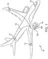
Fig. 1 is a schematic view of an exemplary embodiment of an aircraft electrical system constructed in accordance with the present disclosure, showing a generator connected to a gas turbine engine by an automatic disconnect coupling; -
Fig. 2 is a schematic view of the generator shown inFig. 1 , showing a drive member connected between the gas turbine engine and the generator; -
Fig. 3 is a cross-sectional view of the generator shown inFig. 1 , showing the generator connected to the engine while a retainer retains the disconnect coupling plunger in a disengaged position; -
Fig. 4 is a cross-sectional view of the generator shown inFig. 1 , showing generator disconnected from the engine when the retainer allows the disconnect coupling plunger to move to an engaged position; -
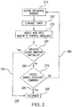
Fig. 5 is a functional schematic view of the generator shown inFig. 1 , showing the disconnect coupling automatically disconnecting the generator from the engine in response to excitation communicated to the solenoid by rotational unbalance of the generator; and - Fig. 6 is process flow diagram of an exemplary embodiment of a method of automatically disconnecting a generator from a gas turbine engine, showing steps of the method.
- Reference will now be made to the drawings wherein like reference numerals identify similar structural features or aspects of the subject disclosure. For purposes of explanation and illustration, and not limitation, a partial view of an exemplary embodiment of an automatic disconnect coupling in accordance with the disclosure is shown in
Fig. 1 and is designated generally byreference character 100. Other embodiments of automatic disconnect couplings, generator having such disconnect couplings, and methods of automatically disconnecting generators in accordance with the disclosure, or aspects thereof, are provided inFigs. 2-6 , as will be described. The systems and methods described herein can be used in aircraft electrical systems, such as for automatic disconnect coupling for generators, though the present disclosure is not limited to aircraft electrical systems or to generator couplings in general. - Referring to
Fig. 1 , an aircraftelectrical system 10 is shown.Electrical system 10 includes a plurality of power-consumingdevices 12 connected to agenerator 102 by apower distribution bus 14.Generator 102 is operably connected to aprime mover 16, e.g., a gas turbine engine, by anautomatic disconnect coupling 100. Although illustrated herein as an aircraft electrical system, it is to be understood and appreciated that the present disclosure can benefit other types of electrical systems. - With reference to
Fig. 2 ,generator 102 is shown.Generator 102 is operably connected togas turbine engine 16 by adrive member 18. In the illustrated exemplary embodiment an accessory gearbox 20 with a constant speed drive 22 is arranged betweengas turbine engine 16 andgenerator 102. Accessory gearbox 20 converts drive rotation 24 fromgas turbine engine 16 into input rotation 26 for rotating arotor portion 106 ofgenerator 102 relative to astator portion 108 ofgenerator 102. Constant speed drive 22 is configured to convert drive rotation 24 provided bygas turbine engine 16 into constant speed input rotation 26, thereby enablinggenerator 102 to rotate at constant speed notwithstanding variable speed operation ofgas turbine engine 16. In anexemplary embodiment generator 102 is configured and adapted for rotation at 6000 rotations per minute (rpm) to apply 235 volts of alternating current (AC) power. Although illustrated inFig. 2 with a constant speed drive arranged in an accessory gearbox, it is also contemplated that a constant speed drive, e.g. a constant speed drive 23 (shown in dashed outline), can be arranged within an integrated drive system generator arrangement. -
Automatic disconnect coupling 100 is arranged on a drive end 101 ofgenerator 102. Arrangingautomatic disconnect coupling 100 of drive end 101 ofgenerator 102 allows for incorporation of an automatic disconnect functionality into legacy generator arrangements. In certain embodiments,automatic disconnect coupling 100 can be arranged on an anti-drive end 103 ofgenerator 102. Arrangingautomatic disconnect coupling 100 on anti-drive end 103 ofgenerator 102 on a side ofgenerator 102 axially opposite drive end 101, providing access toautomatic coupling 100 from a side oppositegas turbine engine 16 and simplifying maintenance. - With reference to
Figs. 3 and4 ,generator 102 is shown.Generator 102 includes arotor portion 106 and astator portion 108.Rotor portion 106 includes aninput member 110 carrying windings orpermanent magnets 112 arranged along arotation axis 114.Input member 110 has face teeth 116 (shown inFig. 2 ) arranged at the generator drive end 101 (shown inFig. 2 ) that oppose face teeth 28 (shown inFig. 2 ) ofdrive member 18, and is movable between a connected position 120 (shown inFig. 2 ) and a disconnect position 122 (shown inFig. 2 ). When in theconnected position 120, the inputmember face teeth 116 intermesh with the drive member face teeth 28 such thatinput member 110 and drivemember 18 are rotationally fixed relative to one another. When in thedisconnected position 122 the inputmember face teeth 116 are axially spaced apart from the drive member face teeth 28 such thatinput member 108 is rotationally free relative to drivemember 18. As will be appreciated, separating the inputmember face teeth 116 from the drive member face teeth 28 disconnect the generator from the rotation source such that the generation rotor stops rotating and power generation ceases. -
Stator portion 108 includeshousing 104, abearing arrangement 124,automatic disconnect coupling 100, andstator windings 126.Bearing arrangement 124 rotatably supportsrotor portion 106 for rotation aboutrotation axis 114.Stator windings 126 are electromagnetically coupled to windings orpermanent magnets 112 such that rotation ofrotor portion 106 aboutrotation axis 114 induces an electrical current instator windings 126, which is available from providing electrical power to power consumingdevices 12 arranged in an aircraftelectrical system 10. -
Automatic disconnect coupling 100 includes aplunger 128 and aretainer 130.Plunger 128 is arranged along aplunger axis 132 and is movable alongplunger axis 132 between anengaged position 134 and a disengaged position 136. Aplunger biasing member 138 biases plunger 128 toward the engagedposition 134.Plunger axis 132 is angled relative torotation axis 114, e.g., at a 90-degree angle, such thatplunger 128 frictionally contacts aramp 140 ofinput member 110 when inengaged position 134. -
Ramp 140 extends circumferentially aboutinput member 110 and is axially sloped alongrotation axis 114. The axial slope oframp 140 is such that frictional contact ofplunger 128 withramp 140 cooperates with rotation ofinput member 110 to displaceinput member 110 alongrotation axis 114 betweenconnected position 120 anddisconnected position 122. An input member biasing 142biases input member 110 toward theconnected position 120 such that, whenplunger 128 is in disengaged position, 136,input member 110 remains rotationally fixed relative to drivemember 18 in theconnected position 120. In the disengaged position 136,plunger 128 is spaced apart frominput member 110. - With reference to
Fig. 5 ,retainer 130 is arranged along a retainer axis 144 between a locked position 146 and an unlocked position 148. In the unlocked position 148retainer 130 is spaced apart fromplunger 128, andplunger biasing member 138 drivesplunger 128 to the engaged position 134 (shown inFig. 4 ) such thatinput member 110 moves fromconnected position 120 todisconnected position 122, disconnectinggenerator 102 fromgas turbine engine 16. In the locked position 146retainer 130 retainsplunger 128 in disengaged position 136,input member 110 remaining inconnected position 120 such thatrotor portion 106 rotates relative tostator portion 108, thereby generating electrical power. - A solenoid 150 is operably connected to
retainer 130. Solenoid 150 includes a core 152, a coil 154, and a retainer biasing member 156. Core 152 is fixed relative toretainer 130 for displacingretainer 130 between locked position 146 and unlocked position 148 along retainer axis 144 upon manual actuation. Manual actuation is effected by application of an actuation current 158 to coil 154, coil 154 extending about core 152 and electromagnetically coupling to core 152 with an electromotive force upon application of actuation current 158 to coil 154. A manual actuation lead 160 is connected to coil 154 for applying actuation current 158 to coil 154, such as by actuation by an operator switch arranged on the flight deck of an aircraft. Solenoid 150 is dynamically coupled toinput member 110 via a damping arrangement 162 with a damping coefficient 164, vibration ofinput member 110 from rotational unbalance ofinput member 110 being communicated therethrough as excitation 166 toretainer 130 and retainer biasing member 156. - Damping coefficient 164 is tuned such that a fundamental frequency of
retainer 130 and retainer biasing member 156 is tuned to the rotational speed ofinput member 110. For example, ifinput member 110 has a rotational speed of 6000 rotations per minute, the fundamental frequency ofretainer 130 and retainer biasing member 156 as a spring-mass system is about 100 hertz. This sensitizesretainer 130 and retainer biasing member 156 to vibrational excitation ofinput member 110, causing vibration ofinput member 110 associated with rotational unbalance ofinput member 110 above a predetermined value displaceretainer 130 from the locked position 146 without application of actuation current 158 to coil 154. As explained above, movement ofretainer 130 from locked position 146 causesinput member 110 to disconnect fromdrive member 18, thereby effecting automatic disconnection ofgenerator 102 fromgas turbine engine 16. It is contemplated that the predetermined value be below a threshold at which vibration, e.g., from failure of a bearing supportinginput member 110, causes excessive noise or damage togenerator 102, accessory gearbox 20, orgas turbine engine 16 connected to inputmember 110. - With reference to Fig. 6, a
method 200 of automatically disconnecting a generator, e.g., generator 102 (shown inFig. 1 ), is shown.Method 200 includes receiving mechanical rotation an input member, e.g.,input member 110, from a source of mechanical rotation, e.g.,gas turbine engine 16, as shown withbox 210. The generator generates electrical power while receiving the mechanical rotation and vibrates according a first amount of rotational unbalance in the rotor portion, e.g., rotor portion 106 (shown inFig. 2 ), as shown withbox 220. A damper with a damping coefficient communicates vibration from the input member to a retainer, e.g.,retainer 130, and retainer biasing member, e.g., retainer biasing member 158, as shown withbox 230. - When the rotational unbalance communicated by the input member is below a predetermined level,
input member 110 remains connected to a drive member, e.g.,drive member 18, as shown withbox 240. When the rotational unbalance communicated by the input member exceeds the predetermined level,input member 110 automatically disconnects from the drive member, as shown withbox 250. The input member can also disconnect from the drive member upon receipt of an actuation current, e.g., actuation current 158, as shown withbox 260. Otherwise, the generator remains connected to the engine and continues to generate electrical power, as shown witharrow 270. - Rotating machinery typically has some amount uneven distribution of mass around an axis of rotation, which is typically referred to as rotating unbalance. Balance in rotating machinery is commonly determined by measuring misalignment between the center of mass of the rotating machine rotor and rotation axis, i.e. the geometric axis, of the rotating machine rotor. The rotating unbalance causes a moment during rotation, giving the rotor a wobbling movement during rotation, which is typically communicated to the stator portion of the rotating machine as vibration. Since vibration can cause noise, operator fatigue, and/or damage to the rotating machine, rotating unbalance is typically limited by balancing the rotating machine rotor and providing damping to stationary components to absorb residual rotating unbalance remaining once the rotor is balanced. In high speed rotating machinery, such as generators for aircraft electrical systems, balance is typically carefully controlled to limit vibration and the associated noise, fatigue, and/or damage that can occur from excessive amounts of vibration.
- One challenge to rotating unbalance is that rotor balance can change during service, for example from bearing wear. If undetected, increased rotating unbalance can exert increased rotating loadings to the static portions of the rotating machine, increasing the magnitude of vibration and noise associated with operation of the rotating machine. If undetected, prolonged operation of the rotating machine with increased rotating unbalance can damage the rotating machine and/or the surrounding structure, reducing availability.
- In embodiments described herein an automatic disconnect coupling is provided which automatically disconnects the rotor of a rotating machine when rotating unbalance exceeds a predetermined level, ceasing application of loads associated with the rotating unbalance on the surrounding structure. In certain embodiments, a spring mass of a coupling retainer is in mechanical communication with the rotating machine rotor to receive excitation therefrom. The spring mass has a fundamental frequency tuned to the rotational speed of the rotating machine rotor such that, when the one per revolution of the excitation of the rotating unbalance exceeds a predetermined value, the spring mass causes a coupling retainer to unlock the coupling, disconnecting the rotor from the source of mechanical rotation. This automatically disconnects the rotor, eliminating the rotating loads that would otherwise be exerted on the surrounding static structure. In accordance with certain embodiments, generators employing such automatic disconnect couplings can be less massive that otherwise required as generator static structure is protected from high static loadings by the automatic disconnect feature of the coupling.
- The methods and systems of the present disclosure, as described above and shown in the drawings, provide for disconnect couplings and generator arrangements with superior properties, including reduced collateral damage to generator and gearbox static structures like housing from generator bearing failures which could otherwise cause in-flight engine shutdowns. While the apparatus and methods of the subject disclosure have been shown and described with reference to preferred embodiments, those skilled in the art will readily appreciate that change and/or modifications may be made thereto without departing from the scope of the subject disclosure.
Claims (15)
- An automatic disconnect coupling (100), comprising:a retainer (130); anda biasing member coupled to the retainer (130) and arranged to communicate excitation from a generator input member (110) to the retainer (130),wherein the retainer (130) and biasing member have a fundamental frequency tuned to rotational speed of the generator input member to automatically disconnect the input member (110) from a drive member (18) when rotating unbalance of the input member exceeds a predetermined level.
- The coupling as recited in claim 1, further comprising a solenoid with a core and a coil operatively connected to the retainer, wherein the retainer is fixed relative to the solenoid core.
- The coupling as recited in claim 2, wherein the solenoid is arranged to communicate vibration of the input member to the retainer and biasing member.
- The coupling as recited cited in claim 2, further comprising a manual disconnect lead connected to the solenoid coil.
- The coupling as recited in claim 2, wherein the retainer has a locked position and an unlocked position defined along a retainer axis, the retainer retaining connection of the input member to the drive member in the locked position, the input member separating from the drive member when displaced from the locked position.
- The coupling as recited in claim 1, further comprising a plunger angled relative to the retainer and having engaged and disengaged positions, wherein the biasing member biases the retainer toward the plunger to lock the plunger in the disengaged position.
- The coupling as recited in claim 6, wherein the plunger has an engaged position, the retainer arranged to lock the plunger in the disengaged position when the rotating unbalance of the input member is below the predetermined level; or
wherein the plunger has an disengaged position, the retainer arranged to allow movement of the plunger to the engaged position when the rotating unbalance of the input member is below the predetermined level. - The coupling as recited in claim 1, further comprising a plunger biasing member urging the plunger toward the input member.
- The coupling as recited in claim 1, wherein the input member includes face teeth and a ramp, wherein the face teeth and ramp are disposed on a common end of the input member.
- The coupling as recited in claim 1, wherein the input member includes face teeth and a ramp, wherein the face teeth and ramp are disposed on opposite ends of the input member.
- A generator arrangement, comprising:an input member arranged along a rotation axis;a stator supporting the input member for rotation about the rotation axis; andan automatic disconnect coupling as recited in claim 1 connected between the stator and the input member, the core being movable along a retainer axis parallel to the rotation axis.
- The generator arrangement as recited in claim 11, further comprising a constant speed drive operably connected to the input member.
- The generator arrangement as recited in claim 12, wherein the constant speed drive and the input member are arranged within a common housing; or
wherein the constant speed drive is housing within an accessory gearbox. - A method of automatically disconnecting a generator input member from a drive member, comprising:exciting a retainer with rotational unbalance of a generator input member;retaining connection of the input member with a drive member when the rotational unbalance at a fundamental frequency of a retainer is below a predetermined value; anddisconnecting the input member from the drive member when the rotational unbalance exceed the predetermined value.
- The method as recited in claim 14, further comprising re-connecting the input member to the drive member, and manually disconnecting the input member from the drive member.
Applications Claiming Priority (1)
| Application Number | Priority Date | Filing Date | Title |
|---|---|---|---|
| US15/418,387 US10132369B2 (en) | 2017-01-27 | 2017-01-27 | Automatically actuated disconnect couplings |
Publications (2)
| Publication Number | Publication Date |
|---|---|
| EP3425230A1 true EP3425230A1 (en) | 2019-01-09 |
| EP3425230B1 EP3425230B1 (en) | 2024-02-28 |
Family
ID=61189210
Family Applications (1)
| Application Number | Title | Priority Date | Filing Date |
|---|---|---|---|
| EP18153542.8A Active EP3425230B1 (en) | 2017-01-27 | 2018-01-25 | Automatically actuated disconnect couplings |
Country Status (2)
| Country | Link |
|---|---|
| US (1) | US10132369B2 (en) |
| EP (1) | EP3425230B1 (en) |
Families Citing this family (3)
| Publication number | Priority date | Publication date | Assignee | Title |
|---|---|---|---|---|
| US10393196B2 (en) * | 2017-06-11 | 2019-08-27 | The Boeing Company | Engine accessory disconnect system |
| GB2592976B (en) * | 2020-03-12 | 2024-03-20 | Safran Electrical & Power | Generator coupling system |
| US12388321B2 (en) | 2021-03-25 | 2025-08-12 | General Electric Company | Gas turbine engine equipped with a control system for management of rotor modes using an electric machine |
Citations (4)
| Publication number | Priority date | Publication date | Assignee | Title |
|---|---|---|---|---|
| US4244455A (en) * | 1978-10-17 | 1981-01-13 | The United States Of America As Represented By The Secretary Of The Navy | Rotary shaft decoupling mechanism |
| US4434881A (en) * | 1981-03-19 | 1984-03-06 | The Garrett Corporation | High speed accessory disconnect apparatus and methods |
| DE102015211588A1 (en) * | 2015-06-23 | 2016-12-29 | Zf Friedrichshafen Ag | Method for controlling an automated friction clutch |
| EP3121473A1 (en) * | 2015-07-15 | 2017-01-25 | Hamilton Sundstrand Corporation | Disconnect mechanisms |
Family Cites Families (10)
| Publication number | Priority date | Publication date | Assignee | Title |
|---|---|---|---|---|
| FR2540647A1 (en) * | 1983-02-04 | 1984-08-10 | Valeo | AUTOMATIC CLUTCH CONTROL DEVICE |
| US4986401A (en) * | 1987-03-26 | 1991-01-22 | Zahnradfabrik Friedrichshaften Ag | Device for controlling an automatic motor-vehicle clutch |
| US5791789A (en) * | 1997-04-24 | 1998-08-11 | United Technologies Corporation | Rotor support for a turbine engine |
| FR2864995B1 (en) * | 2004-01-12 | 2008-01-04 | Snecma Moteurs | DOUBLE RAIDEUR BEARING SUPPORT |
| JP4869008B2 (en) | 2006-09-28 | 2012-02-01 | 株式会社東芝 | Vibration diagnosis system for rotating machinery |
| CN201827630U (en) | 2010-09-29 | 2011-05-11 | 新疆天风发电股份有限公司 | Axial movement monitor device for gear boxes |
| US20120109569A1 (en) | 2010-10-27 | 2012-05-03 | General Electric Company | Diagnosis of bearing thermal anomalies in an electrical machine |
| EP3002566A1 (en) | 2014-09-30 | 2016-04-06 | Alstom Technology Ltd | A system for compensating rotor vibrations |
| US9685841B2 (en) | 2014-11-12 | 2017-06-20 | Honeywell International Inc. | Resettable electro-mechanically actuated connection unit for generators |
| US10208812B2 (en) * | 2014-11-19 | 2019-02-19 | Dana Automotive Systems Group, Llc | Method and system for unlocking an electromagnetic actuator |
-
2017
- 2017-01-27 US US15/418,387 patent/US10132369B2/en active Active
-
2018
- 2018-01-25 EP EP18153542.8A patent/EP3425230B1/en active Active
Patent Citations (4)
| Publication number | Priority date | Publication date | Assignee | Title |
|---|---|---|---|---|
| US4244455A (en) * | 1978-10-17 | 1981-01-13 | The United States Of America As Represented By The Secretary Of The Navy | Rotary shaft decoupling mechanism |
| US4434881A (en) * | 1981-03-19 | 1984-03-06 | The Garrett Corporation | High speed accessory disconnect apparatus and methods |
| DE102015211588A1 (en) * | 2015-06-23 | 2016-12-29 | Zf Friedrichshafen Ag | Method for controlling an automated friction clutch |
| EP3121473A1 (en) * | 2015-07-15 | 2017-01-25 | Hamilton Sundstrand Corporation | Disconnect mechanisms |
Also Published As
| Publication number | Publication date |
|---|---|
| US20180216678A1 (en) | 2018-08-02 |
| EP3425230B1 (en) | 2024-02-28 |
| US10132369B2 (en) | 2018-11-20 |
Similar Documents
| Publication | Publication Date | Title |
|---|---|---|
| US7728477B2 (en) | Dual purpose permanent magnet exciter | |
| US4337406A (en) | Bearing-less remotely journalled dynamo electric machine, particularly alternator for combination with a gas turbine | |
| US6844707B1 (en) | AC/DC brushless starter-generator | |
| JP6194194B2 (en) | Compact electric centrifugal compressor | |
| EP0154626B1 (en) | Uninterruptible power system | |
| EP3425230B1 (en) | Automatically actuated disconnect couplings | |
| US20060087123A1 (en) | Dual-rotor, single input/output starter-generator | |
| RU2434151C2 (en) | Rotor drive of auxiliary unit of gas-turbine engine, support of units for gas-turbine engine, and gas-turbine engine | |
| US8754615B2 (en) | Conversion of synchronous generator to synchronous condenser | |
| US20190128324A1 (en) | Resonance vibration control method and system | |
| EP2372880A2 (en) | Low profile starter-generator | |
| JP6734279B2 (en) | Permanent magnet machine | |
| US11009085B2 (en) | Electromagnetic clutch for gas turbine accessories | |
| EP2815981A1 (en) | Propeller rotor and engine overspeed control | |
| EP1906008A2 (en) | Engine starter-generator optimized for start function | |
| JPS5942551B2 (en) | Excitation device for synchronous rotating electrical machines | |
| US20180131250A1 (en) | Electrical machine | |
| CN102985323A (en) | Electrical power supply for equipment carried by a rotary support | |
| JP2013531579A (en) | Power supply to equipment supported by aircraft engine rotors | |
| EP4130503A1 (en) | System and method to disconnect and brake a rotating device | |
| US6260667B1 (en) | Rotor containment brake | |
| US20180113047A1 (en) | Method and apparatus for turbine engine rotor automatic self balancing | |
| EP2818747B1 (en) | Integrated electromagnetic clutch and eddy-current coupling | |
| US2666509A (en) | Electric motor with built-in flywheel and clutch | |
| EP3065267B1 (en) | Cores for electrical machines |
Legal Events
| Date | Code | Title | Description |
|---|---|---|---|
| PUAI | Public reference made under article 153(3) epc to a published international application that has entered the european phase |
Free format text: ORIGINAL CODE: 0009012 |
|
| STAA | Information on the status of an ep patent application or granted ep patent |
Free format text: STATUS: THE APPLICATION HAS BEEN PUBLISHED |
|
| AK | Designated contracting states |
Kind code of ref document: A1 Designated state(s): AL AT BE BG CH CY CZ DE DK EE ES FI FR GB GR HR HU IE IS IT LI LT LU LV MC MK MT NL NO PL PT RO RS SE SI SK SM TR |
|
| AX | Request for extension of the european patent |
Extension state: BA ME |
|
| STAA | Information on the status of an ep patent application or granted ep patent |
Free format text: STATUS: REQUEST FOR EXAMINATION WAS MADE |
|
| 17P | Request for examination filed |
Effective date: 20190709 |
|
| RBV | Designated contracting states (corrected) |
Designated state(s): AL AT BE BG CH CY CZ DE DK EE ES FI FR GB GR HR HU IE IS IT LI LT LU LV MC MK MT NL NO PL PT RO RS SE SI SK SM TR |
|
| STAA | Information on the status of an ep patent application or granted ep patent |
Free format text: STATUS: EXAMINATION IS IN PROGRESS |
|
| 17Q | First examination report despatched |
Effective date: 20200424 |
|
| GRAP | Despatch of communication of intention to grant a patent |
Free format text: ORIGINAL CODE: EPIDOSNIGR1 |
|
| STAA | Information on the status of an ep patent application or granted ep patent |
Free format text: STATUS: GRANT OF PATENT IS INTENDED |
|
| INTG | Intention to grant announced |
Effective date: 20230908 |
|
| GRAS | Grant fee paid |
Free format text: ORIGINAL CODE: EPIDOSNIGR3 |
|
| GRAA | (expected) grant |
Free format text: ORIGINAL CODE: 0009210 |
|
| STAA | Information on the status of an ep patent application or granted ep patent |
Free format text: STATUS: THE PATENT HAS BEEN GRANTED |
|
| AK | Designated contracting states |
Kind code of ref document: B1 Designated state(s): AL AT BE BG CH CY CZ DE DK EE ES FI FR GB GR HR HU IE IS IT LI LT LU LV MC MK MT NL NO PL PT RO RS SE SI SK SM TR |
|
| REG | Reference to a national code |
Ref country code: GB Ref legal event code: FG4D |
|
| REG | Reference to a national code |
Ref country code: CH Ref legal event code: EP |
|
| REG | Reference to a national code |
Ref country code: DE Ref legal event code: R096 Ref document number: 602018065767 Country of ref document: DE |
|
| REG | Reference to a national code |
Ref country code: IE Ref legal event code: FG4D |
|
| REG | Reference to a national code |
Ref country code: LT Ref legal event code: MG9D |
|
| PG25 | Lapsed in a contracting state [announced via postgrant information from national office to epo] |
Ref country code: IS Free format text: LAPSE BECAUSE OF FAILURE TO SUBMIT A TRANSLATION OF THE DESCRIPTION OR TO PAY THE FEE WITHIN THE PRESCRIBED TIME-LIMIT Effective date: 20240628 |
|
| REG | Reference to a national code |
Ref country code: NL Ref legal event code: MP Effective date: 20240228 |
|
| PG25 | Lapsed in a contracting state [announced via postgrant information from national office to epo] |
Ref country code: LT Free format text: LAPSE BECAUSE OF FAILURE TO SUBMIT A TRANSLATION OF THE DESCRIPTION OR TO PAY THE FEE WITHIN THE PRESCRIBED TIME-LIMIT Effective date: 20240228 |
|
| PG25 | Lapsed in a contracting state [announced via postgrant information from national office to epo] |
Ref country code: GR Free format text: LAPSE BECAUSE OF FAILURE TO SUBMIT A TRANSLATION OF THE DESCRIPTION OR TO PAY THE FEE WITHIN THE PRESCRIBED TIME-LIMIT Effective date: 20240529 |
|
| PG25 | Lapsed in a contracting state [announced via postgrant information from national office to epo] |
Ref country code: RS Free format text: LAPSE BECAUSE OF FAILURE TO SUBMIT A TRANSLATION OF THE DESCRIPTION OR TO PAY THE FEE WITHIN THE PRESCRIBED TIME-LIMIT Effective date: 20240528 Ref country code: NL Free format text: LAPSE BECAUSE OF FAILURE TO SUBMIT A TRANSLATION OF THE DESCRIPTION OR TO PAY THE FEE WITHIN THE PRESCRIBED TIME-LIMIT Effective date: 20240228 Ref country code: HR Free format text: LAPSE BECAUSE OF FAILURE TO SUBMIT A TRANSLATION OF THE DESCRIPTION OR TO PAY THE FEE WITHIN THE PRESCRIBED TIME-LIMIT Effective date: 20240228 |
|
| PG25 | Lapsed in a contracting state [announced via postgrant information from national office to epo] |
Ref country code: ES Free format text: LAPSE BECAUSE OF FAILURE TO SUBMIT A TRANSLATION OF THE DESCRIPTION OR TO PAY THE FEE WITHIN THE PRESCRIBED TIME-LIMIT Effective date: 20240228 |
|
| PG25 | Lapsed in a contracting state [announced via postgrant information from national office to epo] |
Ref country code: RS Free format text: LAPSE BECAUSE OF FAILURE TO SUBMIT A TRANSLATION OF THE DESCRIPTION OR TO PAY THE FEE WITHIN THE PRESCRIBED TIME-LIMIT Effective date: 20240528 Ref country code: NO Free format text: LAPSE BECAUSE OF FAILURE TO SUBMIT A TRANSLATION OF THE DESCRIPTION OR TO PAY THE FEE WITHIN THE PRESCRIBED TIME-LIMIT Effective date: 20240528 Ref country code: NL Free format text: LAPSE BECAUSE OF FAILURE TO SUBMIT A TRANSLATION OF THE DESCRIPTION OR TO PAY THE FEE WITHIN THE PRESCRIBED TIME-LIMIT Effective date: 20240228 Ref country code: LT Free format text: LAPSE BECAUSE OF FAILURE TO SUBMIT A TRANSLATION OF THE DESCRIPTION OR TO PAY THE FEE WITHIN THE PRESCRIBED TIME-LIMIT Effective date: 20240228 Ref country code: IS Free format text: LAPSE BECAUSE OF FAILURE TO SUBMIT A TRANSLATION OF THE DESCRIPTION OR TO PAY THE FEE WITHIN THE PRESCRIBED TIME-LIMIT Effective date: 20240628 Ref country code: HR Free format text: LAPSE BECAUSE OF FAILURE TO SUBMIT A TRANSLATION OF THE DESCRIPTION OR TO PAY THE FEE WITHIN THE PRESCRIBED TIME-LIMIT Effective date: 20240228 Ref country code: GR Free format text: LAPSE BECAUSE OF FAILURE TO SUBMIT A TRANSLATION OF THE DESCRIPTION OR TO PAY THE FEE WITHIN THE PRESCRIBED TIME-LIMIT Effective date: 20240529 Ref country code: FI Free format text: LAPSE BECAUSE OF FAILURE TO SUBMIT A TRANSLATION OF THE DESCRIPTION OR TO PAY THE FEE WITHIN THE PRESCRIBED TIME-LIMIT Effective date: 20240228 Ref country code: ES Free format text: LAPSE BECAUSE OF FAILURE TO SUBMIT A TRANSLATION OF THE DESCRIPTION OR TO PAY THE FEE WITHIN THE PRESCRIBED TIME-LIMIT Effective date: 20240228 Ref country code: BG Free format text: LAPSE BECAUSE OF FAILURE TO SUBMIT A TRANSLATION OF THE DESCRIPTION OR TO PAY THE FEE WITHIN THE PRESCRIBED TIME-LIMIT Effective date: 20240228 |
|
| PG25 | Lapsed in a contracting state [announced via postgrant information from national office to epo] |
Ref country code: PL Free format text: LAPSE BECAUSE OF FAILURE TO SUBMIT A TRANSLATION OF THE DESCRIPTION OR TO PAY THE FEE WITHIN THE PRESCRIBED TIME-LIMIT Effective date: 20240228 Ref country code: PT Free format text: LAPSE BECAUSE OF FAILURE TO SUBMIT A TRANSLATION OF THE DESCRIPTION OR TO PAY THE FEE WITHIN THE PRESCRIBED TIME-LIMIT Effective date: 20240628 |
|
| REG | Reference to a national code |
Ref country code: AT Ref legal event code: MK05 Ref document number: 1661511 Country of ref document: AT Kind code of ref document: T Effective date: 20240228 |
|
| PG25 | Lapsed in a contracting state [announced via postgrant information from national office to epo] |
Ref country code: SE Free format text: LAPSE BECAUSE OF FAILURE TO SUBMIT A TRANSLATION OF THE DESCRIPTION OR TO PAY THE FEE WITHIN THE PRESCRIBED TIME-LIMIT Effective date: 20240228 Ref country code: PT Free format text: LAPSE BECAUSE OF FAILURE TO SUBMIT A TRANSLATION OF THE DESCRIPTION OR TO PAY THE FEE WITHIN THE PRESCRIBED TIME-LIMIT Effective date: 20240628 Ref country code: PL Free format text: LAPSE BECAUSE OF FAILURE TO SUBMIT A TRANSLATION OF THE DESCRIPTION OR TO PAY THE FEE WITHIN THE PRESCRIBED TIME-LIMIT Effective date: 20240228 Ref country code: LV Free format text: LAPSE BECAUSE OF FAILURE TO SUBMIT A TRANSLATION OF THE DESCRIPTION OR TO PAY THE FEE WITHIN THE PRESCRIBED TIME-LIMIT Effective date: 20240228 |
|
| PG25 | Lapsed in a contracting state [announced via postgrant information from national office to epo] |
Ref country code: DK Free format text: LAPSE BECAUSE OF FAILURE TO SUBMIT A TRANSLATION OF THE DESCRIPTION OR TO PAY THE FEE WITHIN THE PRESCRIBED TIME-LIMIT Effective date: 20240228 |
|
| PG25 | Lapsed in a contracting state [announced via postgrant information from national office to epo] |
Ref country code: SM Free format text: LAPSE BECAUSE OF FAILURE TO SUBMIT A TRANSLATION OF THE DESCRIPTION OR TO PAY THE FEE WITHIN THE PRESCRIBED TIME-LIMIT Effective date: 20240228 |
|
| PG25 | Lapsed in a contracting state [announced via postgrant information from national office to epo] |
Ref country code: CZ Free format text: LAPSE BECAUSE OF FAILURE TO SUBMIT A TRANSLATION OF THE DESCRIPTION OR TO PAY THE FEE WITHIN THE PRESCRIBED TIME-LIMIT Effective date: 20240228 Ref country code: EE Free format text: LAPSE BECAUSE OF FAILURE TO SUBMIT A TRANSLATION OF THE DESCRIPTION OR TO PAY THE FEE WITHIN THE PRESCRIBED TIME-LIMIT Effective date: 20240228 |
|
| PG25 | Lapsed in a contracting state [announced via postgrant information from national office to epo] |
Ref country code: AT Free format text: LAPSE BECAUSE OF FAILURE TO SUBMIT A TRANSLATION OF THE DESCRIPTION OR TO PAY THE FEE WITHIN THE PRESCRIBED TIME-LIMIT Effective date: 20240228 |
|
| PG25 | Lapsed in a contracting state [announced via postgrant information from national office to epo] |
Ref country code: SK Free format text: LAPSE BECAUSE OF FAILURE TO SUBMIT A TRANSLATION OF THE DESCRIPTION OR TO PAY THE FEE WITHIN THE PRESCRIBED TIME-LIMIT Effective date: 20240228 |
|
| PG25 | Lapsed in a contracting state [announced via postgrant information from national office to epo] |
Ref country code: SM Free format text: LAPSE BECAUSE OF FAILURE TO SUBMIT A TRANSLATION OF THE DESCRIPTION OR TO PAY THE FEE WITHIN THE PRESCRIBED TIME-LIMIT Effective date: 20240228 Ref country code: SK Free format text: LAPSE BECAUSE OF FAILURE TO SUBMIT A TRANSLATION OF THE DESCRIPTION OR TO PAY THE FEE WITHIN THE PRESCRIBED TIME-LIMIT Effective date: 20240228 Ref country code: RO Free format text: LAPSE BECAUSE OF FAILURE TO SUBMIT A TRANSLATION OF THE DESCRIPTION OR TO PAY THE FEE WITHIN THE PRESCRIBED TIME-LIMIT Effective date: 20240228 Ref country code: EE Free format text: LAPSE BECAUSE OF FAILURE TO SUBMIT A TRANSLATION OF THE DESCRIPTION OR TO PAY THE FEE WITHIN THE PRESCRIBED TIME-LIMIT Effective date: 20240228 Ref country code: DK Free format text: LAPSE BECAUSE OF FAILURE TO SUBMIT A TRANSLATION OF THE DESCRIPTION OR TO PAY THE FEE WITHIN THE PRESCRIBED TIME-LIMIT Effective date: 20240228 Ref country code: CZ Free format text: LAPSE BECAUSE OF FAILURE TO SUBMIT A TRANSLATION OF THE DESCRIPTION OR TO PAY THE FEE WITHIN THE PRESCRIBED TIME-LIMIT Effective date: 20240228 Ref country code: AT Free format text: LAPSE BECAUSE OF FAILURE TO SUBMIT A TRANSLATION OF THE DESCRIPTION OR TO PAY THE FEE WITHIN THE PRESCRIBED TIME-LIMIT Effective date: 20240228 |
|
| REG | Reference to a national code |
Ref country code: DE Ref legal event code: R097 Ref document number: 602018065767 Country of ref document: DE |
|
| PG25 | Lapsed in a contracting state [announced via postgrant information from national office to epo] |
Ref country code: IT Free format text: LAPSE BECAUSE OF FAILURE TO SUBMIT A TRANSLATION OF THE DESCRIPTION OR TO PAY THE FEE WITHIN THE PRESCRIBED TIME-LIMIT Effective date: 20240228 |
|
| PG25 | Lapsed in a contracting state [announced via postgrant information from national office to epo] |
Ref country code: IT Free format text: LAPSE BECAUSE OF FAILURE TO SUBMIT A TRANSLATION OF THE DESCRIPTION OR TO PAY THE FEE WITHIN THE PRESCRIBED TIME-LIMIT Effective date: 20240228 |
|
| PLBE | No opposition filed within time limit |
Free format text: ORIGINAL CODE: 0009261 |
|
| STAA | Information on the status of an ep patent application or granted ep patent |
Free format text: STATUS: NO OPPOSITION FILED WITHIN TIME LIMIT |
|
| 26N | No opposition filed |
Effective date: 20241129 |
|
| PG25 | Lapsed in a contracting state [announced via postgrant information from national office to epo] |
Ref country code: SI Free format text: LAPSE BECAUSE OF FAILURE TO SUBMIT A TRANSLATION OF THE DESCRIPTION OR TO PAY THE FEE WITHIN THE PRESCRIBED TIME-LIMIT Effective date: 20240228 |
|
| REG | Reference to a national code |
Ref country code: CH Ref legal event code: PL |
|
| PG25 | Lapsed in a contracting state [announced via postgrant information from national office to epo] |
Ref country code: MC Free format text: LAPSE BECAUSE OF FAILURE TO SUBMIT A TRANSLATION OF THE DESCRIPTION OR TO PAY THE FEE WITHIN THE PRESCRIBED TIME-LIMIT Effective date: 20240228 Ref country code: LU Free format text: LAPSE BECAUSE OF NON-PAYMENT OF DUE FEES Effective date: 20250125 |
|
| PG25 | Lapsed in a contracting state [announced via postgrant information from national office to epo] |
Ref country code: BE Free format text: LAPSE BECAUSE OF NON-PAYMENT OF DUE FEES Effective date: 20250131 |
|
| PG25 | Lapsed in a contracting state [announced via postgrant information from national office to epo] |
Ref country code: CH Free format text: LAPSE BECAUSE OF NON-PAYMENT OF DUE FEES Effective date: 20250131 |
|
| REG | Reference to a national code |
Ref country code: BE Ref legal event code: MM Effective date: 20250131 |
|
| PGFP | Annual fee paid to national office [announced via postgrant information from national office to epo] |
Ref country code: GB Payment date: 20251217 Year of fee payment: 9 |
|
| PGFP | Annual fee paid to national office [announced via postgrant information from national office to epo] |
Ref country code: FR Payment date: 20251217 Year of fee payment: 9 |
|
| PG25 | Lapsed in a contracting state [announced via postgrant information from national office to epo] |
Ref country code: IE Free format text: LAPSE BECAUSE OF NON-PAYMENT OF DUE FEES Effective date: 20250125 |
|
| PGFP | Annual fee paid to national office [announced via postgrant information from national office to epo] |
Ref country code: DE Payment date: 20251217 Year of fee payment: 9 |