EP3425221B1 - Pump bearing retainer - Google Patents
Pump bearing retainer Download PDFInfo
- Publication number
- EP3425221B1 EP3425221B1 EP17179946.3A EP17179946A EP3425221B1 EP 3425221 B1 EP3425221 B1 EP 3425221B1 EP 17179946 A EP17179946 A EP 17179946A EP 3425221 B1 EP3425221 B1 EP 3425221B1
- Authority
- EP
- European Patent Office
- Prior art keywords
- section
- pump bearing
- pump
- inner section
- bearing retainer
- Prior art date
- Legal status (The legal status is an assumption and is not a legal conclusion. Google has not performed a legal analysis and makes no representation as to the accuracy of the status listed.)
- Active
Links
Images


Classifications
-
- F—MECHANICAL ENGINEERING; LIGHTING; HEATING; WEAPONS; BLASTING
- F04—POSITIVE - DISPLACEMENT MACHINES FOR LIQUIDS; PUMPS FOR LIQUIDS OR ELASTIC FLUIDS
- F04D—NON-POSITIVE-DISPLACEMENT PUMPS
- F04D29/00—Details, component parts, or accessories
- F04D29/04—Shafts or bearings, or assemblies thereof
- F04D29/046—Bearings
-
- F—MECHANICAL ENGINEERING; LIGHTING; HEATING; WEAPONS; BLASTING
- F04—POSITIVE - DISPLACEMENT MACHINES FOR LIQUIDS; PUMPS FOR LIQUIDS OR ELASTIC FLUIDS
- F04D—NON-POSITIVE-DISPLACEMENT PUMPS
- F04D29/00—Details, component parts, or accessories
- F04D29/04—Shafts or bearings, or assemblies thereof
- F04D29/046—Bearings
- F04D29/0465—Ceramic bearing designs
-
- F—MECHANICAL ENGINEERING; LIGHTING; HEATING; WEAPONS; BLASTING
- F16—ENGINEERING ELEMENTS AND UNITS; GENERAL MEASURES FOR PRODUCING AND MAINTAINING EFFECTIVE FUNCTIONING OF MACHINES OR INSTALLATIONS; THERMAL INSULATION IN GENERAL
- F16C—SHAFTS; FLEXIBLE SHAFTS; ELEMENTS OR CRANKSHAFT MECHANISMS; ROTARY BODIES OTHER THAN GEARING ELEMENTS; BEARINGS
- F16C33/00—Parts of bearings; Special methods for making bearings or parts thereof
- F16C33/72—Sealings
- F16C33/76—Sealings of ball or roller bearings
-
- F—MECHANICAL ENGINEERING; LIGHTING; HEATING; WEAPONS; BLASTING
- F04—POSITIVE - DISPLACEMENT MACHINES FOR LIQUIDS; PUMPS FOR LIQUIDS OR ELASTIC FLUIDS
- F04D—NON-POSITIVE-DISPLACEMENT PUMPS
- F04D1/00—Radial-flow pumps, e.g. centrifugal pumps; Helico-centrifugal pumps
-
- F—MECHANICAL ENGINEERING; LIGHTING; HEATING; WEAPONS; BLASTING
- F04—POSITIVE - DISPLACEMENT MACHINES FOR LIQUIDS; PUMPS FOR LIQUIDS OR ELASTIC FLUIDS
- F04D—NON-POSITIVE-DISPLACEMENT PUMPS
- F04D29/00—Details, component parts, or accessories
- F04D29/02—Selection of particular materials
- F04D29/026—Selection of particular materials especially adapted for liquid pumps
-
- F—MECHANICAL ENGINEERING; LIGHTING; HEATING; WEAPONS; BLASTING
- F04—POSITIVE - DISPLACEMENT MACHINES FOR LIQUIDS; PUMPS FOR LIQUIDS OR ELASTIC FLUIDS
- F04D—NON-POSITIVE-DISPLACEMENT PUMPS
- F04D29/00—Details, component parts, or accessories
- F04D29/04—Shafts or bearings, or assemblies thereof
- F04D29/046—Bearings
- F04D29/047—Bearings hydrostatic; hydrodynamic
-
- F—MECHANICAL ENGINEERING; LIGHTING; HEATING; WEAPONS; BLASTING
- F04—POSITIVE - DISPLACEMENT MACHINES FOR LIQUIDS; PUMPS FOR LIQUIDS OR ELASTIC FLUIDS
- F04D—NON-POSITIVE-DISPLACEMENT PUMPS
- F04D29/00—Details, component parts, or accessories
- F04D29/08—Sealings
- F04D29/10—Shaft sealings
- F04D29/12—Shaft sealings using sealing-rings
- F04D29/126—Shaft sealings using sealing-rings especially adapted for liquid pumps
-
- F—MECHANICAL ENGINEERING; LIGHTING; HEATING; WEAPONS; BLASTING
- F04—POSITIVE - DISPLACEMENT MACHINES FOR LIQUIDS; PUMPS FOR LIQUIDS OR ELASTIC FLUIDS
- F04D—NON-POSITIVE-DISPLACEMENT PUMPS
- F04D29/00—Details, component parts, or accessories
- F04D29/60—Mounting; Assembling; Disassembling
- F04D29/62—Mounting; Assembling; Disassembling of radial or helico-centrifugal pumps
- F04D29/628—Mounting; Assembling; Disassembling of radial or helico-centrifugal pumps especially adapted for liquid pumps
-
- F—MECHANICAL ENGINEERING; LIGHTING; HEATING; WEAPONS; BLASTING
- F16—ENGINEERING ELEMENTS AND UNITS; GENERAL MEASURES FOR PRODUCING AND MAINTAINING EFFECTIVE FUNCTIONING OF MACHINES OR INSTALLATIONS; THERMAL INSULATION IN GENERAL
- F16C—SHAFTS; FLEXIBLE SHAFTS; ELEMENTS OR CRANKSHAFT MECHANISMS; ROTARY BODIES OTHER THAN GEARING ELEMENTS; BEARINGS
- F16C35/00—Rigid support of bearing units; Housings, e.g. caps, covers
- F16C35/02—Rigid support of bearing units; Housings, e.g. caps, covers in the case of sliding-contact bearings
-
- F—MECHANICAL ENGINEERING; LIGHTING; HEATING; WEAPONS; BLASTING
- F16—ENGINEERING ELEMENTS AND UNITS; GENERAL MEASURES FOR PRODUCING AND MAINTAINING EFFECTIVE FUNCTIONING OF MACHINES OR INSTALLATIONS; THERMAL INSULATION IN GENERAL
- F16J—PISTONS; CYLINDERS; SEALINGS
- F16J15/00—Sealings
- F16J15/002—Sealings comprising at least two sealings in succession
- F16J15/004—Sealings comprising at least two sealings in succession forming of recuperation chamber for the leaking fluid
-
- F—MECHANICAL ENGINEERING; LIGHTING; HEATING; WEAPONS; BLASTING
- F16—ENGINEERING ELEMENTS AND UNITS; GENERAL MEASURES FOR PRODUCING AND MAINTAINING EFFECTIVE FUNCTIONING OF MACHINES OR INSTALLATIONS; THERMAL INSULATION IN GENERAL
- F16C—SHAFTS; FLEXIBLE SHAFTS; ELEMENTS OR CRANKSHAFT MECHANISMS; ROTARY BODIES OTHER THAN GEARING ELEMENTS; BEARINGS
- F16C2360/00—Engines or pumps
- F16C2360/44—Centrifugal pumps
-
- F—MECHANICAL ENGINEERING; LIGHTING; HEATING; WEAPONS; BLASTING
- F16—ENGINEERING ELEMENTS AND UNITS; GENERAL MEASURES FOR PRODUCING AND MAINTAINING EFFECTIVE FUNCTIONING OF MACHINES OR INSTALLATIONS; THERMAL INSULATION IN GENERAL
- F16C—SHAFTS; FLEXIBLE SHAFTS; ELEMENTS OR CRANKSHAFT MECHANISMS; ROTARY BODIES OTHER THAN GEARING ELEMENTS; BEARINGS
- F16C2361/00—Apparatus or articles in engineering in general
- F16C2361/63—Gears with belts and pulleys
-
- F—MECHANICAL ENGINEERING; LIGHTING; HEATING; WEAPONS; BLASTING
- F16—ENGINEERING ELEMENTS AND UNITS; GENERAL MEASURES FOR PRODUCING AND MAINTAINING EFFECTIVE FUNCTIONING OF MACHINES OR INSTALLATIONS; THERMAL INSULATION IN GENERAL
- F16C—SHAFTS; FLEXIBLE SHAFTS; ELEMENTS OR CRANKSHAFT MECHANISMS; ROTARY BODIES OTHER THAN GEARING ELEMENTS; BEARINGS
- F16C2361/00—Apparatus or articles in engineering in general
- F16C2361/65—Gear shifting, change speed gear, gear box
Definitions
- the present disclosure relates generally to pump bearing retainers, i.e. pump bearing retainers typically used in wet-running pumps, in particular in speed-controlled wet-running centrifugal pumps.
- Wet-running centrifugal pumps usually comprise a rotor can separating a wet-running permanent magnet rotor from a dry stator.
- the rotor drives an impeller located in a pump housing.
- the rotor is usually mounted on a rotor axle which is rotatable within at least one radial bearing.
- the radial bearing is usually circumferentially retained and centred within the pump by a pump bearing retainer, sometimes referred to as bearing plate or disc.
- the pump bearing retainer has a central opening into which the bearing is press-fitted in axial direction during manufacture or assembly. In order to achieve a durable press-fit, the axial pressing forces are usually very high. Therefore, there is a high risk that a bearing breaks or spalls during the press-fit. In particular, ceramic surfaces of bearings may be damaged in this process.
- JP 2003 139151 A describes a motor bearing for preventing spillage of lubricant.
- the motor bearing of JP 2003 139151 A is held against a bearing retainer by a plate.
- embodiments of the present disclosure provide a pump bearing retainer significantly reducing the risk of damaging the bearing when it is press-fitted into the retainer while providing a durable press-fit between the bearing and the retainer. It is a further advantage of the pump bearing retainer according to the present disclosure that the production tolerance limits on both the bearing and the bearing retainer can be released.
- a pump bearing retainer for a wet-running pump comprising a radially inner section comprising an inner section surface for a press-fit contact with an essentially cylinder-shaped radial outer surface of a pump bearing, a radially outer section comprising an annular or essentially conical-shaped outer section surface with a cone angle larger than 45°, and an intermediate section extending from the inner section to the outer section, wherein the intermediate section comprises an essentially conical-shaped intermediate section surface with a cone angle smaller than 45°, wherein the longitudinal cross-section area A of the inner section is smaller than the longitudinal cross-section area B of the intermediate section.
- annular outer section surface shall be equivalent to an essentially conical-shaped outer section surface with a cone angle of 90°.
- the outer section surface may extend over the full outer section or it may extend only partially over the outer section.
- the intermediate section surface may extend over the full intermediate section or it may extend only partially over the intermediate section.
- the cone angle may be constant or vary in radial direction within the outer section and/or within the intermediate section. In case the outer section surface and/or the intermediate section surface is curved, the relevant cone angle ⁇ may be defined here as the average cone angle, i.e.
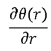
- ⁇ ⁇ R in R out ⁇ ⁇ r ⁇ r dr , wherein 0(r) is the local cone angle defined as the cone angle of a virtual coaxial cone touching the surface tangentially at a radius r, R in is the inner radius of the respective section surface and R out is the outer radius of the respective section surface.
- the smaller longitudinal cross-section area A of the inner section has the beneficial effect that it is less resistant to a radial widening when the bearing is press-fitted into the pump bearing retainer. Thereby, the risk of bearing breaks or spalls during the press-fit is significantly reduced. Furthermore, the radial production tolerance limits on both the bearing and the bearing retainer can be released.
- the inner section may at least be partially deformed in a plastic way, i.e. the inner section would not fully elastically snap back into its initial shape before the press-fit if the bearing were unmounted from the pump bearing retainer.
- the intermediate section may at least be partially deformed in a more flexible way, i.e. the intermediate section would more elastically snap back closer to its initial shape if the bearing were unmounted from the pump bearing retainer.
- the intermediate section may have an elastic behaviour with a smaller hysteresis than the inner section.
- the axial press-in forces during the press-fit may be equivalent to several hundred kilograms or more.
- the longitudinal cross-section area A of the inner section is preferably large enough to provide a sufficiently tight press-fit and to prevent the inner section from tearing apart during the press-fit.
- the inner section surface may be essentially cylinder-shaped for a press-fit contact with an essentially cylinder-shaped radial outer surface of a pump bearing. Thereby, the full inner section surface may provide the necessary frictional contact providing the sufficiently tight press-fit.
- the inner section surface comprises at least one first portion and at least one second portion in circumferential direction, wherein the at least one first portion has a first radius and the at least one second portion has a second radius being larger than the first radius, such that the at least first portion defines at least one contact portion for a press-fit with an essentially cylinder-shaped radial outer surface of a pump bearing, and such that the at least one second portion defines at least one axial fluid channel between the inner section and a pump bearing.
- This is advantageous to further reduce the resistance of the inner section to radial widening and to provide axial fluid channels.
- the inner section may comprise at least one first sub-section and at least one second sub-section in circumferential direction, wherein the at least one first sub-section has a first radial thickness and the at least one second sub-section has a second radial thickness being larger than the first radial thickness.
- This may also further reduce the resistance of the inner section, in particular at the first thinner sub-section to radial widening.
- the thickness may be constant or vary in circumferential direction within the sub-sections and/or between them. The thickness shall be defined here as the average thickness within a sub-section.
- the radial thickness t of the intermediate section may be smaller at an end towards the inner section than at an end towards the outer section. This is beneficial to gradually or step-wisely increase the resistance to radial widening in radial outward direction from the inner section via the intermediate section to the outer section.
- the outer section, or at least a radially outer rim of the outer section, is preferably not widened at all during the press-fit.
- the axial length h of the inner section surface may be shorter than the axial length X of the intermediate section surface, wherein the ratio X/h is preferably in the range of 2 to 4.
- the longer axial length X of the intermediate section surface allows for a more flexible radial widening providing the necessary radial inward pressure to achieve a sufficiently tight press-fit of the bearing with the pump bearing retainer.
- the intermediate section may be more flexible in radial direction than the outer section, i.e. the inner diameter of the intermediate section widens more than the inner diameter of the outer section during the press-fit.
- the pump bearing retainer may further comprise a pump bearing press-fitted into the inner section.
- the pump bearing retainer may be specifically optimised to retain such a pump bearing.
- the pump bearing may be a radial bearing with an inner sliding surface for a sliding contact with a rotor axle of a pump, wherein the pump bearing preferably comprises a ceramic surface.
- the pump bearing retainer may be optimized for the pump bearing having a radial outer surface with an axial length H by designing the inner section surface with an axial length h smaller than half of the axial length H of the radial outer surface of the pump bearing, i.e. h ⁇ H/2, preferably h ⁇ H/3.
- an axial upper end of the inner section surface may have an axial distance p to an axial upper end of the radial outer surface of the pump bearing, wherein 0.2 ⁇ (H-h) ⁇ p ⁇ 0.8 ⁇ (H-h).
- an axial lower end of the inner section surface may have an axial distance q to an axial lower end of the radial outer surface of the pump bearing, wherein 0.2 ⁇ (H-h) ⁇ q ⁇ 0.8 ⁇ (H-h).
- a pump comprising a pump bearing retainer as described above, wherein the pump is a centrifugal pump for conveying water in a heating system.
- the market for such household pumps is large and competitive. Therefore, the production of such pumps is optimized to allow a high production rate while minimizing deficiencies due to breaks or spalls of ceramic bearings that must be scrapped.
- a centrifugal pump for conveying water in a heating system with a pump bearing retainer as described above can be produced at lower cost due to less breaks or spalls of expensive ceramic bearings.
- Fig. 1 shows a pump bearing retainer 1 comprising an inner section 3, an intermediate section 5 and an outer section 7.
- the pump bearing retainer 1 is in this first embodiment is integrally and homogenously made of a single material, preferably a sheet of metal, and rotationally symmetric with respect to a longitudinal axis L.
- the pump bearing retainer 1 may be forged, milled, cut, fettled, burred, moulded, grinded, rolled, 3D-printed (additively manufactured) and/or pressed into the shown hat-like shape.
- a pump bearing 13 (see. Fig. 2 ) is to be press-fitted from below (see hollow arrow) into the pump bearing retainer 1.
- the relevant surfaces of the pump bearing retainer 1 are here the bottom and inner surfaces.
- the pump bearing retainer 1 may have any spatial orientation, so that terms like “below”, “above”, “under”, “upper”, “vertical”, “horizontal” etc. are to be interpreted in a reference frame fixed to the pump bearing retain
- the inner section 3 comprises an inner section surface 9 defining a central circular opening 11 with a radius R 1 into which a pump bearing can be press-fitted.
- the intermediate section 5 defines an essentially conical-shaped intermediate section surface 15 ranging from the radius R 1 to a radius R 2 , where an outer section surface 17 of the outer section 5 starts.
- the outer section 7, ranging from the intermediate section surface 15 to an outer radius R 3 forms essentially a brim comprising four outer sub-sections, i.e.
- annular first outer sub-section 16 defining a peripheral face 19 with the outer radius R 3 for centring the pump bearing retainer 1 within a pump housing (not shown), a cylinder-shaped second outer sub-section 21 stiffening the outer section 7, an annular third outer sub-section 23, and a conical-shaped fourth sub-section 25.
- the first outer sub-section 16, the second outer sub-section 21 and the annular third outer sub-section 23 are arranged in an essentially Z-shaped or S-shaped configuration to stiffen the outer section 7.
- the outer section surface 17 is essentially conical-shaped and has a cone angle ⁇ 1 above 45°.
- the fourth outer sub-section 25 could be annular, resulting in a cone angle ⁇ 1 of 90°.
- the non-conical sub-sections i.e. the annular first outer sub-section 16, the cylindrical second outer sub-section 21 and the annular third outer sub-section 23 may not contribute to the cone angle ⁇ 1 of the outer section surface 17.
- the intermediate section 5 connects the outer section 7 with the inner section 3.
- the transition line between the outer section 7 and the intermediate section 5 may be defined by a virtual normal N on a virtual coaxial cone touching the surface tangentially and having cone angle of 45°.
- the transition line between the intermediate section 5 and the inner section 3 may be defined here by a virtual horizontal plane Q through the lowest point of the cylindrical inner section surface 9.
- the magnified view in Fig. 1 a better view on the longitudinal cross-section area A of the inner section 3 and the longitudinal cross-section area B of the intermediate section 5.
- the inner section 3 has a significantly less longitudinal cross-section area than the intermediate section 5, i.e. A ⁇ B, preferably A ⁇ B/3.
- the inner section 3 is less resistant to a radial widening when a pump bearing is press-fitted into the pump bearing retainer 1. Thereby, the risk of breaks or spalls of a ceramic pump bearing during the press-fit is significantly reduced.
- the inner section 3 may at least be partially widened in a plastic way, i.e.
- the inner section 3 would not fully elastically snap back into its initial shape if the pump bearing were unmounted from the pump bearing retainer 1.
- the intermediate section 5 may at least be partially widened in a more flexible way, i.e. the intermediate section 5 would more elastically snap back closer to its initial shape if the pump bearing were unmounted from the pump bearing retainer 1.
- the intermediate section 5 may have an elastic behaviour with a smaller hysteresis than the inner section 3.
- the intermediate section 5 has thus a spring effect to keep a press-fitted pump bearing in place while the inner section 3 provides the minimum frictional surface, i.e. inner section surface 9, to keep the pump bearing in place.
- the radial thickness t of the intermediate section 5 is in this embodiment smaller at an end towards the inner section 3 than at an end towards the outer section 5.
- the axial length h of the inner section surface 9 is shorter than the axial length X of the intermediate section surface 15, wherein the ratio X/h is preferably in the range of 2 to 4. Due to the shape of the pump bearing retainer 1, the intermediate section 5 is also more flexible in radial direction than the outer section 7.
- the outer section 7 thus contributes to the required stiffness of the pump bearing retainer 1 and the intermediate section 5 contributes to the required flexibility of the pump bearing retainer 1 for permanently and reliably retaining the pump bearing 13 by press-fit.
- the inner section 3 contributes to the required plasticity of the pump bearing retainer 1 to avoid cracks, spalls and breaks of the pump bearing during press-fit.
- the inner section 3 is configured to deform at least partially plastically when a pump bearing is press-fitted into the inner section 3.
- Fig. 2 shows the pump bearing retainer 1 with an annular-shaped pump bearing 13 press-fitted into the inner section 3.
- the pump bearing 13 is a radial bearing with a cylindrical inner sliding surface 27 for a sliding contact with a coaxial rotor axle of a pump.
- the pump bearing 13 comprises a ceramic surface.
- the pump bearing 13 is fully made of ceramic material.
- the inner and outer edges of the pump bearing 13 are chamfered to facilitate the insertion during press-fit and to avoid spalls at the edges.
- the pump bearing comprises a radial outer surface 29 with an axial length H, wherein the inner section surface 9 has an axial length h smaller than half of the axial length H of the radial outer surface 29 of the pump bearing, i.e. h ⁇ H/2. Furthermore, an axial upper end 31 of the inner section surface 9 has an axial distance p to an axial upper end 33 of the radial outer surface 29 of the pump bearing 13, wherein 0.2 ⁇ (H-h) ⁇ p ⁇ 0.8 ⁇ (H-h). This makes sure that the pump bearing 13 is inserted deeply enough into the pump bearing retainer 1, but not too much.
- an axial lower end 35 of the inner section surface 9 has an axial distance q to an axial lower end 37 of the radial outer surface 29 of the pump bearing 13, wherein 0.2 ⁇ (H-h) ⁇ q ⁇ 0.8 ⁇ (H-h).
- the top view of Fig. 3 on the inner section 3 shows an embodiment in which the inner section 3 comprises a first sub-section 39 and a second sub-section 41 in circumferential direction, wherein the first sub-section 39 has a first radial thickness D 1 and the second sub-section 41 has a second radial thickness D 2 being larger than the first radial thickness D 1 .
- the sections may be arbitrarily defined as diametrically opposite sub-sections.
- the inner section 3 may at least partially plastically deform during the press-fit mostly in the area of the thinner first section 39.
- the embodiment of Fig. 4 shows the inner section 3 being "crenelated” in radial direction forming eight “crenels".
- the crenels 43 each form an axial fluid channel with essentially rectangular cross-section between the inner section 3 and a pump bearing 13.
- the inner section surface 9 comprises eight first portions 45 and eight second portions 47 in circumferential direction, wherein each first portion 45 has a first radius R i and each second portion 47 has a second radius R o being larger than the first radius R i , such that the eight first portions 45 define eight contact portions for a press-fit with an essentially cylinder-shaped radial outer surface 29 of a pump bearing 13, and such that the eight second portions 47 define eight axial fluid channels between the inner section 3 and a pump bearing 13.
- Fig. 5 shows a similar embodiment like Fig. 4 , but only with six axial fluid channels.
- the second portions 47 in this case are concavely shaped radial protrusions with a smoothly curved transition between the first portions 45 and the second portions 47.
Landscapes
- Engineering & Computer Science (AREA)
- General Engineering & Computer Science (AREA)
- Mechanical Engineering (AREA)
- Physics & Mathematics (AREA)
- Fluid Mechanics (AREA)
- Chemical & Material Sciences (AREA)
- Ceramic Engineering (AREA)
- Structures Of Non-Positive Displacement Pumps (AREA)
Description
- The present disclosure relates generally to pump bearing retainers, i.e. pump bearing retainers typically used in wet-running pumps, in particular in speed-controlled wet-running centrifugal pumps.
- Wet-running centrifugal pumps usually comprise a rotor can separating a wet-running permanent magnet rotor from a dry stator. The rotor drives an impeller located in a pump housing. The rotor is usually mounted on a rotor axle which is rotatable within at least one radial bearing. The radial bearing is usually circumferentially retained and centred within the pump by a pump bearing retainer, sometimes referred to as bearing plate or disc. The pump bearing retainer has a central opening into which the bearing is press-fitted in axial direction during manufacture or assembly. In order to achieve a durable press-fit, the axial pressing forces are usually very high. Therefore, there is a high risk that a bearing breaks or spalls during the press-fit. In particular, ceramic surfaces of bearings may be damaged in this process.
-
JP 2003 139151 A JP 2003 139151 A - In contrast to known pump bearing retainers, embodiments of the present disclosure provide a pump bearing retainer significantly reducing the risk of damaging the bearing when it is press-fitted into the retainer while providing a durable press-fit between the bearing and the retainer. It is a further advantage of the pump bearing retainer according to the present disclosure that the production tolerance limits on both the bearing and the bearing retainer can be released.
- In accordance with a first aspect of the present disclosure, a pump bearing retainer for a wet-running pump is provided comprising a radially inner section comprising an inner section surface for a press-fit contact with an essentially cylinder-shaped radial outer surface of a pump bearing, a radially outer section comprising an annular or essentially conical-shaped outer section surface with a cone angle larger than 45°, and an intermediate section extending from the inner section to the outer section, wherein the intermediate section comprises an essentially conical-shaped intermediate section surface with a cone angle smaller than 45°, wherein the longitudinal cross-section area A of the inner section is smaller than the longitudinal cross-section area B of the intermediate section.
- Herein, an annular outer section surface shall be equivalent to an essentially conical-shaped outer section surface with a cone angle of 90°. The outer section surface may extend over the full outer section or it may extend only partially over the outer section. Analogously, the intermediate section surface may extend over the full intermediate section or it may extend only partially over the intermediate section. The cone angle may be constant or vary in radial direction within the outer section and/or within the intermediate section. In case the outer section surface and/or the intermediate section surface is curved, the relevant cone angle θ may be defined here as the average cone angle, i.e.


- The smaller longitudinal cross-section area A of the inner section has the beneficial effect that it is less resistant to a radial widening when the bearing is press-fitted into the pump bearing retainer. Thereby, the risk of bearing breaks or spalls during the press-fit is significantly reduced. Furthermore, the radial production tolerance limits on both the bearing and the bearing retainer can be released.
- During the press-fit, the inner section may at least be partially deformed in a plastic way, i.e. the inner section would not fully elastically snap back into its initial shape before the press-fit if the bearing were unmounted from the pump bearing retainer. Compared to the inner section, the intermediate section may at least be partially deformed in a more flexible way, i.e. the intermediate section would more elastically snap back closer to its initial shape if the bearing were unmounted from the pump bearing retainer. In other words, the intermediate section may have an elastic behaviour with a smaller hysteresis than the inner section.
- The axial press-in forces during the press-fit may be equivalent to several hundred kilograms or more. Thus, the longitudinal cross-section area A of the inner section is preferably large enough to provide a sufficiently tight press-fit and to prevent the inner section from tearing apart during the press-fit. Optionally, the inner section surface may be essentially cylinder-shaped for a press-fit contact with an essentially cylinder-shaped radial outer surface of a pump bearing. Thereby, the full inner section surface may provide the necessary frictional contact providing the sufficiently tight press-fit.
- According to the present invention, the inner section surface comprises at least one first portion and at least one second portion in circumferential direction, wherein the at least one first portion has a first radius and the at least one second portion has a second radius being larger than the first radius, such that the at least first portion defines at least one contact portion for a press-fit with an essentially cylinder-shaped radial outer surface of a pump bearing, and such that the at least one second portion defines at least one axial fluid channel between the inner section and a pump bearing. This is advantageous to further reduce the resistance of the inner section to radial widening and to provide axial fluid channels.
- Alternatively or in addition, the inner section may comprise at least one first sub-section and at least one second sub-section in circumferential direction, wherein the at least one first sub-section has a first radial thickness and the at least one second sub-section has a second radial thickness being larger than the first radial thickness. This may also further reduce the resistance of the inner section, in particular at the first thinner sub-section to radial widening. The thickness may be constant or vary in circumferential direction within the sub-sections and/or between them. The thickness shall be defined here as the average thickness within a sub-section.
- Optionally, the radial thickness t of the intermediate section may be smaller at an end towards the inner section than at an end towards the outer section. This is beneficial to gradually or step-wisely increase the resistance to radial widening in radial outward direction from the inner section via the intermediate section to the outer section. The outer section, or at least a radially outer rim of the outer section, is preferably not widened at all during the press-fit.
- Optionally, the axial length h of the inner section surface may be shorter than the axial length X of the intermediate section surface, wherein the ratio X/h is preferably in the range of 2 to 4. The longer axial length X of the intermediate section surface allows for a more flexible radial widening providing the necessary radial inward pressure to achieve a sufficiently tight press-fit of the bearing with the pump bearing retainer.
- Optionally, the intermediate section may be more flexible in radial direction than the outer section, i.e. the inner diameter of the intermediate section widens more than the inner diameter of the outer section during the press-fit.
- Optionally, the pump bearing retainer may further comprise a pump bearing press-fitted into the inner section. Once the pump bearing and its dimensions is known, the pump bearing retainer may be specifically optimised to retain such a pump bearing. For instance, the pump bearing may be a radial bearing with an inner sliding surface for a sliding contact with a rotor axle of a pump, wherein the pump bearing preferably comprises a ceramic surface. Optionally, the pump bearing retainer may be optimized for the pump bearing having a radial outer surface with an axial length H by designing the inner section surface with an axial length h smaller than half of the axial length H of the radial outer surface of the pump bearing, i.e. h < H/2, preferably h < H/3.
- Alternatively or in addition, an axial upper end of the inner section surface may have an axial distance p to an axial upper end of the radial outer surface of the pump bearing, wherein 0.2·(H-h) < p < 0.8·(H-h). Likewise, alternatively or in addition, an axial lower end of the inner section surface may have an axial distance q to an axial lower end of the radial outer surface of the pump bearing, wherein 0.2·(H-h) < q < 0.8·(H-h). Thereby, the inner section may be axially centred with respect to the bearing to prevent the pump bearing retainer from slipping off the bearing. Thus, the axial production tolerance limits on both the bearing and the bearing retainer can be released.
- In accordance with a second aspect of the present disclosure, a pump is provided comprising a pump bearing retainer as described above, wherein the pump is a centrifugal pump for conveying water in a heating system. The market for such household pumps is large and competitive. Therefore, the production of such pumps is optimized to allow a high production rate while minimizing deficiencies due to breaks or spalls of ceramic bearings that must be scrapped. A centrifugal pump for conveying water in a heating system with a pump bearing retainer as described above can be produced at lower cost due to less breaks or spalls of expensive ceramic bearings.
- Embodiments of the present disclosure will now be described by way of example with reference to the following figures of which:
-
Fig. 1 shows a cross-sectional view on an example of a pump bearing retainer according to a first embodiment of the present disclosure; -
Fig. 2 shows a more detailed partial cross-sectional view on an example of a pump bearing retainer with a press-fitted bearing according to a first embodiment of the present disclosure; -
Fig. 3 shows a top view on an inner section of an example of a pump bearing retainer according to a second embodiment of the present disclosure; -
Fig. 4 shows a top view on an inner section of an example of a pump bearing retainer according to a third embodiment of the present disclosure; and -
Fig. 5 shows a top view on an inner section of an example of a pump bearing retainer according to a fourth embodiment of the present disclosure. -
Fig. 1 shows apump bearing retainer 1 comprising aninner section 3, anintermediate section 5 and anouter section 7. Thepump bearing retainer 1 is in this first embodiment is integrally and homogenously made of a single material, preferably a sheet of metal, and rotationally symmetric with respect to a longitudinal axis L. Thepump bearing retainer 1 may be forged, milled, cut, fettled, burred, moulded, grinded, rolled, 3D-printed (additively manufactured) and/or pressed into the shown hat-like shape. A pump bearing 13 (see.Fig. 2 ) is to be press-fitted from below (see hollow arrow) into thepump bearing retainer 1. Thus, the relevant surfaces of thepump bearing retainer 1 are here the bottom and inner surfaces. It should be noted that thepump bearing retainer 1 may have any spatial orientation, so that terms like "below", "above", "under", "upper", "vertical", "horizontal" etc. are to be interpreted in a reference frame fixed to thepump bearing retainer 1. - The
inner section 3 comprises aninner section surface 9 defining a centralcircular opening 11 with a radius R1 into which a pump bearing can be press-fitted. Theintermediate section 5 defines an essentially conical-shapedintermediate section surface 15 ranging from the radius R1 to a radius R2, where anouter section surface 17 of theouter section 5 starts. Theouter section 7, ranging from theintermediate section surface 15 to an outer radius R3, forms essentially a brim comprising four outer sub-sections, i.e. an annular firstouter sub-section 16 defining aperipheral face 19 with the outer radius R3 for centring thepump bearing retainer 1 within a pump housing (not shown), a cylinder-shaped secondouter sub-section 21 stiffening theouter section 7, an annular thirdouter sub-section 23, and a conical-shapedfourth sub-section 25. The firstouter sub-section 16, the secondouter sub-section 21 and the annular thirdouter sub-section 23 are arranged in an essentially Z-shaped or S-shaped configuration to stiffen theouter section 7. - In the area of the conical-shaped
fourth sub-section 25, theouter section surface 17 is essentially conical-shaped and has a cone angle θ1 above 45°. It should be noted that, alternatively, the fourthouter sub-section 25 could be annular, resulting in a cone angle θ1 of 90°. In order to increase the stiffness of theouter section 7, the fourthouter sub-section 25 is here slightly convexly curved, so that, strictly speaking, the cone angle θ1 of theouter section surface 17 is defined as
outer sub-section 16, the cylindrical secondouter sub-section 21 and the annular thirdouter sub-section 23 may not contribute to the cone angle θ1 of theouter section surface 17. - The
intermediate section 5 connects theouter section 7 with theinner section 3. The transition line between theouter section 7 and theintermediate section 5 may be defined by a virtual normal N on a virtual coaxial cone touching the surface tangentially and having cone angle of 45°. The transition line between theintermediate section 5 and theinner section 3 may be defined here by a virtual horizontal plane Q through the lowest point of the cylindricalinner section surface 9. The essentially conical-shapedintermediate section surface 15 ranging from the radius R1 to a radius R2 has a cone angle θ2 of less than 45°. As the local cone angle θ(r) varies slightly with radius r, the cone angle θ2 of theintermediate section surface 15 may be defined as
- The magnified view in
Fig. 1 a better view on the longitudinal cross-section area A of theinner section 3 and the longitudinal cross-section area B of theintermediate section 5. Theinner section 3 has a significantly less longitudinal cross-section area than theintermediate section 5, i.e. A < B, preferably A < B/3. Thus, theinner section 3 is less resistant to a radial widening when a pump bearing is press-fitted into thepump bearing retainer 1. Thereby, the risk of breaks or spalls of a ceramic pump bearing during the press-fit is significantly reduced. During the press-fit, theinner section 3 may at least be partially widened in a plastic way, i.e. theinner section 3 would not fully elastically snap back into its initial shape if the pump bearing were unmounted from thepump bearing retainer 1. Compared to theinner section 3, theintermediate section 5 may at least be partially widened in a more flexible way, i.e. theintermediate section 5 would more elastically snap back closer to its initial shape if the pump bearing were unmounted from thepump bearing retainer 1. In other words, theintermediate section 5 may have an elastic behaviour with a smaller hysteresis than theinner section 3. - The
intermediate section 5 has thus a spring effect to keep a press-fitted pump bearing in place while theinner section 3 provides the minimum frictional surface, i.e.inner section surface 9, to keep the pump bearing in place. In order to improve the overall integrity, stability and flexibility, the radial thickness t of theintermediate section 5 is in this embodiment smaller at an end towards theinner section 3 than at an end towards theouter section 5. Furthermore, the axial length h of theinner section surface 9 is shorter than the axial length X of theintermediate section surface 15, wherein the ratio X/h is preferably in the range of 2 to 4. Due to the shape of thepump bearing retainer 1, theintermediate section 5 is also more flexible in radial direction than theouter section 7. Theouter section 7 thus contributes to the required stiffness of thepump bearing retainer 1 and theintermediate section 5 contributes to the required flexibility of thepump bearing retainer 1 for permanently and reliably retaining thepump bearing 13 by press-fit. Theinner section 3 contributes to the required plasticity of thepump bearing retainer 1 to avoid cracks, spalls and breaks of the pump bearing during press-fit. In other words, theinner section 3 is configured to deform at least partially plastically when a pump bearing is press-fitted into theinner section 3. -
Fig. 2 shows thepump bearing retainer 1 with an annular-shaped pump bearing 13 press-fitted into theinner section 3. Thepump bearing 13 is a radial bearing with a cylindrical inner slidingsurface 27 for a sliding contact with a coaxial rotor axle of a pump. Thepump bearing 13 comprises a ceramic surface. Preferably, thepump bearing 13 is fully made of ceramic material. Here, the inner and outer edges of thepump bearing 13 are chamfered to facilitate the insertion during press-fit and to avoid spalls at the edges. - The pump bearing comprises a radial
outer surface 29 with an axial length H, wherein theinner section surface 9 has an axial length h smaller than half of the axial length H of the radialouter surface 29 of the pump bearing, i.e. h < H/2. Furthermore, an axialupper end 31 of theinner section surface 9 has an axial distance p to an axialupper end 33 of the radialouter surface 29 of thepump bearing 13, wherein 0.2·(H-h) < p < 0.8·(H-h). This makes sure that thepump bearing 13 is inserted deeply enough into thepump bearing retainer 1, but not too much. Analogously, an axiallower end 35 of theinner section surface 9 has an axial distance q to an axiallower end 37 of the radialouter surface 29 of thepump bearing 13, wherein 0.2·(H-h) < q < 0.8·(H-h). - The top view of
Fig. 3 on theinner section 3 shows an embodiment in which theinner section 3 comprises afirst sub-section 39 and asecond sub-section 41 in circumferential direction, wherein thefirst sub-section 39 has a first radial thickness D1 and thesecond sub-section 41 has a second radial thickness D2 being larger than the first radial thickness D1. If the radial thickness varies in circumferential direction as shown, the sections may be arbitrarily defined as diametrically opposite sub-sections. Theinner section 3 may at least partially plastically deform during the press-fit mostly in the area of the thinnerfirst section 39. - The embodiment of
Fig. 4 shows theinner section 3 being "crenelated" in radial direction forming eight "crenels". Thecrenels 43 each form an axial fluid channel with essentially rectangular cross-section between theinner section 3 and apump bearing 13. In other words, theinner section surface 9 comprises eightfirst portions 45 and eightsecond portions 47 in circumferential direction, wherein eachfirst portion 45 has a first radius Ri and eachsecond portion 47 has a second radius Ro being larger than the first radius Ri, such that the eightfirst portions 45 define eight contact portions for a press-fit with an essentially cylinder-shaped radialouter surface 29 of apump bearing 13, and such that the eightsecond portions 47 define eight axial fluid channels between theinner section 3 and apump bearing 13. -
Fig. 5 shows a similar embodiment likeFig. 4 , but only with six axial fluid channels. Thesecond portions 47 in this case are concavely shaped radial protrusions with a smoothly curved transition between thefirst portions 45 and thesecond portions 47. - Where, in the foregoing description, integers or elements are mentioned which have known, obvious or foreseeable equivalents, then such equivalents are herein incorporated as if individually set forth. Reference should be made to the claims for determining the true scope of the present disclosure, which should be construed so as to encompass any such equivalents. It will also be appreciated by the reader that integers or features of the disclosure that are described as optional, preferable, advantageous, convenient or the like are optional and do not limit the scope of the independent claims.
- The above embodiments are to be understood as illustrative examples of the disclosure. It is to be understood that any feature described in relation to any one embodiment may be used alone, or in combination with other features described, and may also be used in combination with one or more features of any other of the embodiments, or any combination of any other of the embodiments. While at least one exemplary embodiment has been shown and described, it should be understood that other modifications, substitutions and alternatives are apparent to one of ordinary skill in the art and may be changed without departing from the scope of the claims.
- In addition, "comprising" does not exclude other elements or steps, and "a" or "one" does not exclude a plural number. Furthermore, characteristics or steps which have been described with reference to one of the above exemplary embodiments may also be used in combination with other characteristics or steps of other exemplary embodiments described above. Method steps may be applied in any order or in parallel or may constitute a part or a more detailed version of another method step. It should be understood that there should be embodied within the scope of the patent warranted hereon all such modifications as reasonably and properly come within the scope of the contribution to the art. Such modifications, substitutions and alternatives can be made without departing from the scope of the claims.
Claims (14)
- A pump bearing retainer (1) for a wet-running pump comprising- a radially inner section (3) comprising an inner section surface (9) for a press-fit contact with an essentially cylinder-shaped radial outer surface (29) of a pump bearing (13),- a radially outer section (7) comprising an annular or essentially conical-shaped outer section surface (17) with a cone angle (θ1) equal to or larger than 45°, and- an intermediate section (5) extending from the inner section (3) to the outer section (7), wherein the intermediate section (5) comprises an essentially conical-shaped intermediate section surface (15) with a cone angle (θ2) smaller than 45°,wherein the longitudinal cross-section area A of the inner section (3) is smaller than the longitudinal cross-section area B of the intermediate section (5), characterised in that
the inner section surface (9) comprises at least one first portion (45) and at least one second portion (47) in circumferential direction, wherein the at least one first portion (45) has a first radius (Ri) and the at least one second portion (47) has a second radius (Ro) being larger than the first radius (Ri), such that the at least first portion (45) defines at least one contact portion for a press-fit with an essentially cylinder-shaped radial outer surface (29) of a pump bearing (13), and such that the at least one second portion (47) defines at least one axial fluid channel between the inner section (3) and a pump bearing (13). - The pump bearing retainer (1) according to claim 1, wherein the inner section surface (9) is essentially cylinder-shaped.
- The pump bearing retainer (1) according to any of the preceding claims, wherein the inner section (3) comprises at least one first sub-section (39) and at least one second sub-section (41) in circumferential direction, wherein the at least one first sub-section (39) has a first radial thickness (D1) and the at least one second sub-section (41) has a second radial thickness (D2) being larger than the first radial thickness (D1).
- The pump bearing retainer (1) according to any of the preceding claims, wherein the radial thickness t of the intermediate section (5) is smaller at an end towards the inner section (3) than at an end towards the outer section (7).
- The pump bearing retainer (1) according to any of the preceding claims, wherein the axial length h of the inner section surface (9) is shorter than the axial length X of the intermediate section surface (15), wherein the ratio X/h is preferably in the range of 2 to 4.
- The pump bearing retainer (1) according to any of the preceding claims, wherein the intermediate section (5) is more flexible in radial direction than the outer section (7).
- The pump bearing retainer (1) according to any of the preceding claims, wherein the inner section (3) is configured to deform at least partially plastically when a pump bearing (13) is press-fitted into the inner section (3).
- The pump bearing retainer (1) according to any of the preceding claims, further comprising a pump bearing (13) press-fitted into the inner section (3).
- The pump bearing retainer (1) according to claim 8, wherein the pump bearing (13) is a radial bearing with an inner sliding surface (27) for a sliding contact with a rotor axle of a pump.
- The pump bearing retainer (1) according to claim 8 or 9, wherein the pump bearing (13) comprises a ceramic surface.
- The pump bearing retainer (1) according to any of the claims 8 to 10, wherein the pump bearing (13) comprises a radial outer surface (29) with an axial length H, wherein the inner section surface (9) has an axial length h smaller than half of the axial length H of the radial outer surface (29) of the pump bearing (13), i.e. h < H/2.
- The pump bearing retainer (1) according to any of the claims 8 to 11, wherein an axial upper end (31) of the inner section surface (9) has an axial distance p to an axial upper end (33) of the radial outer surface (29) of the pump bearing (13), wherein 0.2 · (H - h) < p < 0.8 · (H - h).
- The pump bearing retainer according to any of the claims 8 to 12, wherein an axial lower end (35) of the inner section surface (9) has an axial distance q to an axial lower end (37) of the radial outer surface (29) of the pump bearing (13), wherein 0.2 · (H - h) < q < 0.8 · (H - h).
- A pump comprising a pump bearing retainer (1) according to any of the preceding claims, wherein the pump is a centrifugal pump for conveying water in a heating system.
Priority Applications (6)
| Application Number | Priority Date | Filing Date | Title |
|---|---|---|---|
| SI201730188T SI3425221T1 (en) | 2017-07-06 | 2017-07-06 | Pump bearing retainer |
| PL17179946T PL3425221T3 (en) | 2017-07-06 | 2017-07-06 | Pump bearing retainer |
| EP17179946.3A EP3425221B1 (en) | 2017-07-06 | 2017-07-06 | Pump bearing retainer |
| CN201810567506.9A CN109209981B (en) | 2017-07-06 | 2018-06-05 | pump bearing retainer |
| RU2018123514A RU2705532C1 (en) | 2017-07-06 | 2018-06-28 | Pump bearing holder |
| US16/027,509 US10823186B2 (en) | 2017-07-06 | 2018-07-05 | Pump bearing retainer |
Applications Claiming Priority (1)
| Application Number | Priority Date | Filing Date | Title |
|---|---|---|---|
| EP17179946.3A EP3425221B1 (en) | 2017-07-06 | 2017-07-06 | Pump bearing retainer |
Publications (2)
| Publication Number | Publication Date |
|---|---|
| EP3425221A1 EP3425221A1 (en) | 2019-01-09 |
| EP3425221B1 true EP3425221B1 (en) | 2019-11-20 |
Family
ID=59295038
Family Applications (1)
| Application Number | Title | Priority Date | Filing Date |
|---|---|---|---|
| EP17179946.3A Active EP3425221B1 (en) | 2017-07-06 | 2017-07-06 | Pump bearing retainer |
Country Status (6)
| Country | Link |
|---|---|
| US (1) | US10823186B2 (en) |
| EP (1) | EP3425221B1 (en) |
| CN (1) | CN109209981B (en) |
| PL (1) | PL3425221T3 (en) |
| RU (1) | RU2705532C1 (en) |
| SI (1) | SI3425221T1 (en) |
Cited By (1)
| Publication number | Priority date | Publication date | Assignee | Title |
|---|---|---|---|---|
| EP3851677A1 (en) | 2020-01-17 | 2021-07-21 | Grundfos Holding A/S | Pump bearing retainer |
Families Citing this family (1)
| Publication number | Priority date | Publication date | Assignee | Title |
|---|---|---|---|---|
| CN116792411A (en) * | 2023-05-26 | 2023-09-22 | 鸣志电器(太仓)有限公司 | Bearing retainer for pump and centrifugal pump unit with bearing retainer |
Family Cites Families (16)
| Publication number | Priority date | Publication date | Assignee | Title |
|---|---|---|---|---|
| FR2366483A1 (en) * | 1976-10-04 | 1978-04-28 | Ina Roulements Sa | Bearing for engine cooling fluid pump - has two seals retaining fluid and lubricant respectively with vented air gap between |
| US4240677A (en) * | 1979-01-25 | 1980-12-23 | Payne Douglas L | Bearing mounting device and bearing |
| DE3803774A1 (en) * | 1988-02-09 | 1989-08-17 | Grundfos Int | PUMP UNIT FOR HEATING SYSTEMS |
| US5385413A (en) * | 1993-12-09 | 1995-01-31 | The Torrington Company | Bearing assembly with axial retention |
| DE19548471C1 (en) * | 1995-12-22 | 1997-06-05 | Grundfos As | Circulation pump system e.g. for wet-running motor |
| US6150743A (en) * | 1997-04-24 | 2000-11-21 | Electric Boat Corporation | Composite motor end housing with a metallic sleeve bearing support |
| DE19914579C2 (en) * | 1999-03-31 | 2001-03-08 | Grundfos As | Centrifugal pump unit |
| JP2003139151A (en) * | 2001-11-07 | 2003-05-14 | Asmo Co Ltd | Bearing device and motor provided with the bearing device |
| US20030173156A1 (en) * | 2002-03-14 | 2003-09-18 | Borcherding Gary W. | Lubricant retention assembly |
| US6971802B2 (en) * | 2003-12-23 | 2005-12-06 | Vezina Martin J | Bearing preload cage assembly |
| EP2110928B2 (en) * | 2008-04-19 | 2016-06-01 | Grundfos Management A/S | Stator housing components for a canned motor |
| RU2405974C1 (en) * | 2009-04-15 | 2010-12-10 | Закрытое акционерное общество "Помпа" | Centrifugal pump with wet-type motor |
| DE102011086460A1 (en) * | 2011-11-16 | 2013-05-16 | Robert Bosch Gmbh | Liquid pump with axial thrust washer |
| DE102011119626A1 (en) * | 2011-11-29 | 2013-05-29 | Wilo Se | Glandless pump motor |
| PL2607710T3 (en) * | 2011-12-23 | 2015-08-31 | Grundfos Holding As | Wet running circulation pump |
| DE102013004339A1 (en) * | 2013-03-14 | 2014-09-18 | Wilo Se | Pump unit with a one-piece bearing unit |
-
2017
- 2017-07-06 EP EP17179946.3A patent/EP3425221B1/en active Active
- 2017-07-06 SI SI201730188T patent/SI3425221T1/en unknown
- 2017-07-06 PL PL17179946T patent/PL3425221T3/en unknown
-
2018
- 2018-06-05 CN CN201810567506.9A patent/CN109209981B/en not_active Expired - Fee Related
- 2018-06-28 RU RU2018123514A patent/RU2705532C1/en active
- 2018-07-05 US US16/027,509 patent/US10823186B2/en not_active Expired - Fee Related
Non-Patent Citations (1)
| Title |
|---|
| None * |
Cited By (3)
| Publication number | Priority date | Publication date | Assignee | Title |
|---|---|---|---|---|
| EP3851677A1 (en) | 2020-01-17 | 2021-07-21 | Grundfos Holding A/S | Pump bearing retainer |
| RU2754880C1 (en) * | 2020-01-17 | 2021-09-08 | Грундфос Холдинг А/С | Pump bearing lock |
| US12110901B2 (en) | 2020-01-17 | 2024-10-08 | Grundfos Holding A/S | Pump bearing retainer |
Also Published As
| Publication number | Publication date |
|---|---|
| SI3425221T1 (en) | 2020-04-30 |
| US20190010950A1 (en) | 2019-01-10 |
| CN109209981A (en) | 2019-01-15 |
| US10823186B2 (en) | 2020-11-03 |
| RU2705532C1 (en) | 2019-11-07 |
| CN109209981B (en) | 2020-05-22 |
| EP3425221A1 (en) | 2019-01-09 |
| PL3425221T3 (en) | 2020-05-18 |
Similar Documents
| Publication | Publication Date | Title |
|---|---|---|
| CN101220756B (en) | Axial rotor section for a rotor of a turbine | |
| US10598218B2 (en) | Angular contact roller bearing and method and device for the assembly thereof | |
| RU2426889C2 (en) | Device for axial retention of rotor disc flange, as well as turbine of turbomachine, and turbomachine containing such device | |
| US6675942B2 (en) | Friction plate | |
| CN107407386B (en) | Axial retention and anti-rotation structures for hydrodynamic thrust bearings | |
| US10823186B2 (en) | Pump bearing retainer | |
| JP2016521339A (en) | Spherical roller bearing cage with cylindrical guide contact surface and radially outwardly directed inner flange | |
| US9841064B2 (en) | Reduced drag clutch plate | |
| GB2269629A (en) | Clamp sleeve | |
| US10030698B2 (en) | Bearing ring for rolling-element bearing | |
| US9212687B2 (en) | Twist lock flat thrust washer assembly | |
| CN110520643A (en) | Rolling bearing unit having snap ring and method for removing snap ring | |
| CN113107967A (en) | Bearing assembly | |
| EP3739228B1 (en) | Fan dynamic pressure structure having a plastic frame integrally formed around an oil-containing sintered metal powder bearing | |
| CN209761776U (en) | Fan with cooling device | |
| KR102270697B1 (en) | One-way clutch, method for manufacturing the same and torque converter comprising the same | |
| CN216216230U (en) | Motor and drive member | |
| US11193538B2 (en) | Bearing cage assembly including stiffening ring | |
| KR101742331B1 (en) | Freewheel clutch | |
| US20090028715A1 (en) | Impeller | |
| US12631210B2 (en) | Foil bearing | |
| JP2014181735A (en) | Crown type cage and ball bearing | |
| JP2019122086A (en) | Motor and fan | |
| CN209925261U (en) | Dynamic pressure structure of fan with plastic frame and oil-containing metal powder bearing integrally formed | |
| CN117515048A (en) | Bearing assembly |
Legal Events
| Date | Code | Title | Description |
|---|---|---|---|
| PUAI | Public reference made under article 153(3) epc to a published international application that has entered the european phase |
Free format text: ORIGINAL CODE: 0009012 |
|
| STAA | Information on the status of an ep patent application or granted ep patent |
Free format text: STATUS: THE APPLICATION HAS BEEN PUBLISHED |
|
| AK | Designated contracting states |
Kind code of ref document: A1 Designated state(s): AL AT BE BG CH CY CZ DE DK EE ES FI FR GB GR HR HU IE IS IT LI LT LU LV MC MK MT NL NO PL PT RO RS SE SI SK SM TR |
|
| AX | Request for extension of the european patent |
Extension state: BA ME |
|
| STAA | Information on the status of an ep patent application or granted ep patent |
Free format text: STATUS: REQUEST FOR EXAMINATION WAS MADE |
|
| 17P | Request for examination filed |
Effective date: 20190424 |
|
| RBV | Designated contracting states (corrected) |
Designated state(s): AL AT BE BG CH CY CZ DE DK EE ES FI FR GB GR HR HU IE IS IT LI LT LU LV MC MK MT NL NO PL PT RO RS SE SI SK SM TR |
|
| RIC1 | Information provided on ipc code assigned before grant |
Ipc: F16J 15/00 20060101ALI20190514BHEP Ipc: F16C 33/76 20060101AFI20190514BHEP Ipc: F04D 29/12 20060101ALI20190514BHEP |
|
| GRAP | Despatch of communication of intention to grant a patent |
Free format text: ORIGINAL CODE: EPIDOSNIGR1 |
|
| STAA | Information on the status of an ep patent application or granted ep patent |
Free format text: STATUS: GRANT OF PATENT IS INTENDED |
|
| INTG | Intention to grant announced |
Effective date: 20190709 |
|
| GRAS | Grant fee paid |
Free format text: ORIGINAL CODE: EPIDOSNIGR3 |
|
| GRAA | (expected) grant |
Free format text: ORIGINAL CODE: 0009210 |
|
| STAA | Information on the status of an ep patent application or granted ep patent |
Free format text: STATUS: THE PATENT HAS BEEN GRANTED |
|
| AK | Designated contracting states |
Kind code of ref document: B1 Designated state(s): AL AT BE BG CH CY CZ DE DK EE ES FI FR GB GR HR HU IE IS IT LI LT LU LV MC MK MT NL NO PL PT RO RS SE SI SK SM TR |
|
| REG | Reference to a national code |
Ref country code: GB Ref legal event code: FG4D |
|
| REG | Reference to a national code |
Ref country code: CH Ref legal event code: EP |
|
| REG | Reference to a national code |
Ref country code: IE Ref legal event code: FG4D |
|
| REG | Reference to a national code |
Ref country code: DE Ref legal event code: R096 Ref document number: 602017008840 Country of ref document: DE |
|
| REG | Reference to a national code |
Ref country code: AT Ref legal event code: REF Ref document number: 1204516 Country of ref document: AT Kind code of ref document: T Effective date: 20191215 |
|
| REG | Reference to a national code |
Ref country code: NL Ref legal event code: MP Effective date: 20191120 |
|
| REG | Reference to a national code |
Ref country code: LT Ref legal event code: MG4D |
|
| PG25 | Lapsed in a contracting state [announced via postgrant information from national office to epo] |
Ref country code: LV Free format text: LAPSE BECAUSE OF FAILURE TO SUBMIT A TRANSLATION OF THE DESCRIPTION OR TO PAY THE FEE WITHIN THE PRESCRIBED TIME-LIMIT Effective date: 20191120 Ref country code: SE Free format text: LAPSE BECAUSE OF FAILURE TO SUBMIT A TRANSLATION OF THE DESCRIPTION OR TO PAY THE FEE WITHIN THE PRESCRIBED TIME-LIMIT Effective date: 20191120 Ref country code: NO Free format text: LAPSE BECAUSE OF FAILURE TO SUBMIT A TRANSLATION OF THE DESCRIPTION OR TO PAY THE FEE WITHIN THE PRESCRIBED TIME-LIMIT Effective date: 20200220 Ref country code: GR Free format text: LAPSE BECAUSE OF FAILURE TO SUBMIT A TRANSLATION OF THE DESCRIPTION OR TO PAY THE FEE WITHIN THE PRESCRIBED TIME-LIMIT Effective date: 20200221 Ref country code: NL Free format text: LAPSE BECAUSE OF FAILURE TO SUBMIT A TRANSLATION OF THE DESCRIPTION OR TO PAY THE FEE WITHIN THE PRESCRIBED TIME-LIMIT Effective date: 20191120 Ref country code: LT Free format text: LAPSE BECAUSE OF FAILURE TO SUBMIT A TRANSLATION OF THE DESCRIPTION OR TO PAY THE FEE WITHIN THE PRESCRIBED TIME-LIMIT Effective date: 20191120 Ref country code: FI Free format text: LAPSE BECAUSE OF FAILURE TO SUBMIT A TRANSLATION OF THE DESCRIPTION OR TO PAY THE FEE WITHIN THE PRESCRIBED TIME-LIMIT Effective date: 20191120 Ref country code: BG Free format text: LAPSE BECAUSE OF FAILURE TO SUBMIT A TRANSLATION OF THE DESCRIPTION OR TO PAY THE FEE WITHIN THE PRESCRIBED TIME-LIMIT Effective date: 20200220 |
|
| PG25 | Lapsed in a contracting state [announced via postgrant information from national office to epo] |
Ref country code: IS Free format text: LAPSE BECAUSE OF FAILURE TO SUBMIT A TRANSLATION OF THE DESCRIPTION OR TO PAY THE FEE WITHIN THE PRESCRIBED TIME-LIMIT Effective date: 20200320 Ref country code: HR Free format text: LAPSE BECAUSE OF FAILURE TO SUBMIT A TRANSLATION OF THE DESCRIPTION OR TO PAY THE FEE WITHIN THE PRESCRIBED TIME-LIMIT Effective date: 20191120 Ref country code: RS Free format text: LAPSE BECAUSE OF FAILURE TO SUBMIT A TRANSLATION OF THE DESCRIPTION OR TO PAY THE FEE WITHIN THE PRESCRIBED TIME-LIMIT Effective date: 20191120 |
|
| PG25 | Lapsed in a contracting state [announced via postgrant information from national office to epo] |
Ref country code: AL Free format text: LAPSE BECAUSE OF FAILURE TO SUBMIT A TRANSLATION OF THE DESCRIPTION OR TO PAY THE FEE WITHIN THE PRESCRIBED TIME-LIMIT Effective date: 20191120 |
|
| PG25 | Lapsed in a contracting state [announced via postgrant information from national office to epo] |
Ref country code: PT Free format text: LAPSE BECAUSE OF FAILURE TO SUBMIT A TRANSLATION OF THE DESCRIPTION OR TO PAY THE FEE WITHIN THE PRESCRIBED TIME-LIMIT Effective date: 20200412 Ref country code: EE Free format text: LAPSE BECAUSE OF FAILURE TO SUBMIT A TRANSLATION OF THE DESCRIPTION OR TO PAY THE FEE WITHIN THE PRESCRIBED TIME-LIMIT Effective date: 20191120 Ref country code: RO Free format text: LAPSE BECAUSE OF FAILURE TO SUBMIT A TRANSLATION OF THE DESCRIPTION OR TO PAY THE FEE WITHIN THE PRESCRIBED TIME-LIMIT Effective date: 20191120 Ref country code: DK Free format text: LAPSE BECAUSE OF FAILURE TO SUBMIT A TRANSLATION OF THE DESCRIPTION OR TO PAY THE FEE WITHIN THE PRESCRIBED TIME-LIMIT Effective date: 20191120 Ref country code: ES Free format text: LAPSE BECAUSE OF FAILURE TO SUBMIT A TRANSLATION OF THE DESCRIPTION OR TO PAY THE FEE WITHIN THE PRESCRIBED TIME-LIMIT Effective date: 20191120 Ref country code: CZ Free format text: LAPSE BECAUSE OF FAILURE TO SUBMIT A TRANSLATION OF THE DESCRIPTION OR TO PAY THE FEE WITHIN THE PRESCRIBED TIME-LIMIT Effective date: 20191120 |
|
| REG | Reference to a national code |
Ref country code: AT Ref legal event code: MK05 Ref document number: 1204516 Country of ref document: AT Kind code of ref document: T Effective date: 20191120 |
|
| REG | Reference to a national code |
Ref country code: DE Ref legal event code: R097 Ref document number: 602017008840 Country of ref document: DE |
|
| PG25 | Lapsed in a contracting state [announced via postgrant information from national office to epo] |
Ref country code: SM Free format text: LAPSE BECAUSE OF FAILURE TO SUBMIT A TRANSLATION OF THE DESCRIPTION OR TO PAY THE FEE WITHIN THE PRESCRIBED TIME-LIMIT Effective date: 20191120 Ref country code: SK Free format text: LAPSE BECAUSE OF FAILURE TO SUBMIT A TRANSLATION OF THE DESCRIPTION OR TO PAY THE FEE WITHIN THE PRESCRIBED TIME-LIMIT Effective date: 20191120 |
|
| PLBE | No opposition filed within time limit |
Free format text: ORIGINAL CODE: 0009261 |
|
| STAA | Information on the status of an ep patent application or granted ep patent |
Free format text: STATUS: NO OPPOSITION FILED WITHIN TIME LIMIT |
|
| 26N | No opposition filed |
Effective date: 20200821 |
|
| PG25 | Lapsed in a contracting state [announced via postgrant information from national office to epo] |
Ref country code: AT Free format text: LAPSE BECAUSE OF FAILURE TO SUBMIT A TRANSLATION OF THE DESCRIPTION OR TO PAY THE FEE WITHIN THE PRESCRIBED TIME-LIMIT Effective date: 20191120 |
|
| PG25 | Lapsed in a contracting state [announced via postgrant information from national office to epo] |
Ref country code: MC Free format text: LAPSE BECAUSE OF FAILURE TO SUBMIT A TRANSLATION OF THE DESCRIPTION OR TO PAY THE FEE WITHIN THE PRESCRIBED TIME-LIMIT Effective date: 20191120 |
|
| REG | Reference to a national code |
Ref country code: CH Ref legal event code: PL |
|
| REG | Reference to a national code |
Ref country code: BE Ref legal event code: MM Effective date: 20200731 |
|
| PG25 | Lapsed in a contracting state [announced via postgrant information from national office to epo] |
Ref country code: LI Free format text: LAPSE BECAUSE OF NON-PAYMENT OF DUE FEES Effective date: 20200731 Ref country code: LU Free format text: LAPSE BECAUSE OF NON-PAYMENT OF DUE FEES Effective date: 20200706 Ref country code: CH Free format text: LAPSE BECAUSE OF NON-PAYMENT OF DUE FEES Effective date: 20200731 Ref country code: IE Free format text: LAPSE BECAUSE OF NON-PAYMENT OF DUE FEES Effective date: 20200706 |
|
| PG25 | Lapsed in a contracting state [announced via postgrant information from national office to epo] |
Ref country code: BE Free format text: LAPSE BECAUSE OF NON-PAYMENT OF DUE FEES Effective date: 20200731 |
|
| PG25 | Lapsed in a contracting state [announced via postgrant information from national office to epo] |
Ref country code: TR Free format text: LAPSE BECAUSE OF FAILURE TO SUBMIT A TRANSLATION OF THE DESCRIPTION OR TO PAY THE FEE WITHIN THE PRESCRIBED TIME-LIMIT Effective date: 20191120 Ref country code: MT Free format text: LAPSE BECAUSE OF FAILURE TO SUBMIT A TRANSLATION OF THE DESCRIPTION OR TO PAY THE FEE WITHIN THE PRESCRIBED TIME-LIMIT Effective date: 20191120 Ref country code: CY Free format text: LAPSE BECAUSE OF FAILURE TO SUBMIT A TRANSLATION OF THE DESCRIPTION OR TO PAY THE FEE WITHIN THE PRESCRIBED TIME-LIMIT Effective date: 20191120 |
|
| PG25 | Lapsed in a contracting state [announced via postgrant information from national office to epo] |
Ref country code: MK Free format text: LAPSE BECAUSE OF FAILURE TO SUBMIT A TRANSLATION OF THE DESCRIPTION OR TO PAY THE FEE WITHIN THE PRESCRIBED TIME-LIMIT Effective date: 20191120 |
|
| REG | Reference to a national code |
Ref country code: DE Ref legal event code: R082 Ref document number: 602017008840 Country of ref document: DE |
|
| PGFP | Annual fee paid to national office [announced via postgrant information from national office to epo] |
Ref country code: PL Payment date: 20230622 Year of fee payment: 7 |
|
| PGFP | Annual fee paid to national office [announced via postgrant information from national office to epo] |
Ref country code: IT Payment date: 20230724 Year of fee payment: 7 Ref country code: GB Payment date: 20230721 Year of fee payment: 7 |
|
| PGFP | Annual fee paid to national office [announced via postgrant information from national office to epo] |
Ref country code: SI Payment date: 20230623 Year of fee payment: 7 Ref country code: FR Payment date: 20230726 Year of fee payment: 7 Ref country code: DE Payment date: 20230719 Year of fee payment: 7 |
|
| REG | Reference to a national code |
Ref country code: DE Ref legal event code: R119 Ref document number: 602017008840 Country of ref document: DE |
|
| GBPC | Gb: european patent ceased through non-payment of renewal fee |
Effective date: 20240706 |
|
| PG25 | Lapsed in a contracting state [announced via postgrant information from national office to epo] |
Ref country code: DE Free format text: LAPSE BECAUSE OF NON-PAYMENT OF DUE FEES Effective date: 20250201 |
|
| PG25 | Lapsed in a contracting state [announced via postgrant information from national office to epo] |
Ref country code: FR Free format text: LAPSE BECAUSE OF NON-PAYMENT OF DUE FEES Effective date: 20240731 |
|
| PG25 | Lapsed in a contracting state [announced via postgrant information from national office to epo] |
Ref country code: GB Free format text: LAPSE BECAUSE OF NON-PAYMENT OF DUE FEES Effective date: 20240706 |
|
| PG25 | Lapsed in a contracting state [announced via postgrant information from national office to epo] |
Ref country code: IT Free format text: LAPSE BECAUSE OF NON-PAYMENT OF DUE FEES Effective date: 20240706 |
|
| REG | Reference to a national code |
Ref country code: SI Ref legal event code: KO00 Effective date: 20240707 |
|
| PG25 | Lapsed in a contracting state [announced via postgrant information from national office to epo] |
Ref country code: PL Free format text: LAPSE BECAUSE OF NON-PAYMENT OF DUE FEES Effective date: 20240706 |
|
| PG25 | Lapsed in a contracting state [announced via postgrant information from national office to epo] |
Ref country code: SI Free format text: LAPSE BECAUSE OF NON-PAYMENT OF DUE FEES Effective date: 20240707 |