EP3425134A1 - Slope-adjustable supporter - Google Patents
Slope-adjustable supporter Download PDFInfo
- Publication number
- EP3425134A1 EP3425134A1 EP18177319.3A EP18177319A EP3425134A1 EP 3425134 A1 EP3425134 A1 EP 3425134A1 EP 18177319 A EP18177319 A EP 18177319A EP 3425134 A1 EP3425134 A1 EP 3425134A1
- Authority
- EP
- European Patent Office
- Prior art keywords
- support plate
- arc surface
- slope
- height
- screw
- Prior art date
- Legal status (The legal status is an assumption and is not a legal conclusion. Google has not performed a legal analysis and makes no representation as to the accuracy of the status listed.)
- Withdrawn
Links
Images

Classifications
-
- E—FIXED CONSTRUCTIONS
- E04—BUILDING
- E04F—FINISHING WORK ON BUILDINGS, e.g. STAIRS, FLOORS
- E04F15/00—Flooring
- E04F15/02—Flooring or floor layers composed of a number of similar elements
- E04F15/024—Sectional false floors, e.g. computer floors
- E04F15/02447—Supporting structures
- E04F15/02464—Height adjustable elements for supporting the panels or a panel-supporting framework
- E04F15/0247—Screw jacks
- E04F15/02482—Screw jacks with a variable angle between panel and support
-
- E—FIXED CONSTRUCTIONS
- E04—BUILDING
- E04F—FINISHING WORK ON BUILDINGS, e.g. STAIRS, FLOORS
- E04F15/00—Flooring
- E04F15/02—Flooring or floor layers composed of a number of similar elements
- E04F15/024—Sectional false floors, e.g. computer floors
- E04F15/02447—Supporting structures
- E04F15/02464—Height adjustable elements for supporting the panels or a panel-supporting framework
- E04F15/0247—Screw jacks
- E04F15/02476—Screw jacks height-adjustable from the upper side of the floor
Definitions
- the present disclosure relates to a stilt device, and more particularly relates to a supporter.
- Supporters are applied to fields such as waterscape fountains, balcony gardens, and square paving, e.g., stilting a WPC (Wood- Plastic Composites) or metal keel, and supporting a raised stone floor, etc.
- a constructed road surface or top layer will be sloped to avoid water accumulation.
- the slope is relatively small, construction quality issues such as uneven and displaced floor tiles easily occur when typical or universal supporters are used.
- An objective of the present disclosure is to provide a supporter adapted to stilting woodwork plates, ceramic tiles, and stonework like marble to be paved on a sloped ground surface.
- a slope-adjustable supporter comprising: a base, a support plate, and a height-adjusting part that is disposed between the base and the support plate to adjust a height of the support plate through thread fit, a top portion of the height-adjusting part being provided with a recessed arc surface, a bottom portion of the support plate being provided with a convex arc surface, the convex arc surface being supported inside the recessed arc surface and being slidable relative to the recessed arc surface.
- the height-adjusting part comprises a screw having the recessed arc surface, a center of the support plate being provided with a through-hole, a center of the screw being provided with a convex column protruding above the recessed arc surface, a center of the convex column being provided with a plug hole into which a wrench driving the screw to rotate is insertable.
- an anti-rotation plug preventing a relative rotation is disposed between the support plate and the screw.
- catch positions are evenly distributed at an outer wall of the convex column along a peripheral direction
- the anti-rotation plug is provided with catch bosses for being caught into the catch positions
- the anti-rotation plug is provided with a plug pin for being plugged into the plug hole.
- positioning convex ribs distributed in a cross shape are provided at a top face of the support plate around a center of the top face.
- a rubber gasket is provided on the support plate.
- a material-saving recessed groove is opened in an upper plane of the support plate.
- the technical solution of the present disclosure mainly involves horizontal adjustment and height adjustment of the plastic supporter, wherein the height adjustment scheme achieves change of the product height by rotating male and female threads of the height adjustment part, and the horizontal adjustment scheme achieves horizontal adjustment in such a manner as: providing a recessed arc surface at a top portion of the height adjustment part, and providing a convex arc surface at a bottom portion of the support plate, the convex arc surface of the support plate being slidable within a certain range in the recessed arc surface of the top portion of the height adjustment part, such that when the product is placed on a ground surface with a certain slope, due to gravity or external force, sliding of the support plate will cause a change to the included angle between the support plate and the ground surface, and by calibration with a tool, supported faces may become horizontal.
- the supporter in this technical solution enables stilting of slabs and stonework tiles on a sloped ground surface and enables the mounted slabs and stonework tiles to meet designed standards.
- a slope-adjusted supporter 1 comprising a base 10, a support plate 13, and a height adjustment part disposed between the base 10 and the support plate 13 to adjust a height of the support plate through thread fit, the support plate 13 being slidable relative to the height adjustment part.
- the height adjustment part comprises a screw 12.
- a recessed arc surface 122 is provided at a top portion of the screw
- a convex arc surface 134 is provided at a bottom portion of the support plate
- the convex arc surface 134 is supported inside the recessed arc surface 122 to implement the relative sliding.
- an upper plane of the support plate is parallel to a lower plane of the base.
- an included angle between the upper plane of the support plate and the sloped face will change after the convex arc surface 134 supported in the recessed arc face 122 has a relative slide, and the upper plane of the support plate may be calibrated to be horizontal through a level gauge.
- a center of the support plate is provided with a through-hole 132
- a center of the screw is provided with a convex column 123 protruding above the recessed arc surface.
- the convex column functions to limit a movable range of the support plate and prevent the supporter from sliding off.
- a center of the convex column is provided with a plug hole 1231. As illustrated in Fig. 5 , a wrench 16 driving the screw 12 to rotate may be inserted in the plug hole 1231.
- the wrench 16 is in a T shape, a head portion of which has a drive head 161, the drive head 161 being inserted into the plug hole 1231, rotation of the wrench 16 drives rotation of the screw 12 to thereby implement height adjustment of the screw 12.
- the drive head 161 and the plug hole 1231 may have a variety of shapes, e.g., an elongated bar shape adopted in this embodiment, or various kinds of polygonal shapes.
- catch positions 1232 are evenly distributed at an outer wall of the convex column along a peripheral direction.
- the anti-rotation plug 15 is provided with a catch boss 152 for being caught in the catch positions 1232 and a plug pin 151 for being plugged in the plug hole 1231, wherein positioning of the anti-rotation plug 15 is implemented by plugging the plug pin 151 into the plug hole 1231, such that the anti-rotation plug 15 will not be displaced freely; and the catch boss 152 being caught in the catch position 1232 achieves the objective of limiting the support plate from sliding.
- the present disclosure is mainly applied to support a ground tile 2, wherein positioning convex ribs 131 distributed in a cross shape are provided at a top face of the support plate around a center of the top face. Corners of the floor tile are positioned by the positioning convex ribs, which facilitates paving and positioning of the floor tile.
- the positioning convex ribs 131 may be snapped or cut off. For example, when the floor tiles are completely paved for final finish, the positioning convex ribs 131 may be removed.
- a rubber gasket 14 is provided on the support plate 13, for achieving sufficient contact between the floor tile and the supporter as well as a slide-proof.
- a wrench via-hole 141 is provided at a center of the rubber gasket for the wrench 16 to pass through to thereby adjust rotation of the screw 12.
- the anti-rotation plug 15 it is also available for the anti-rotation plug 15 to pass through.
- a bar-shaped hole 142 for the positioning convex ribs 131 to pass through is provided at the rubber gasket 14 surrounding the wrench via-hole.
- a material-saving groove 133 is opened in the upper plane of the support plate.
- the material-saving groove is disposed to correspond to a bottom portion convex arc surface of the support plate, which may reduce consumption of the material, reduce weight, and lower cost, without affecting the strength of the support plate per se.
- the height adjustment part further comprises an adjusting disc 11 having a screw part 111.
- a center of the adjusting disc is hollow and provided with an inner thread fitted to the screw 12, the base 10 is provided with a threaded sleeve part 101 having an inner thread, the inner thread of the threaded sleeve part being fitted with the external thread of the screw part.
- height may be adjusted through thread fitting between the adjusting disc 11 and the screw 12 and between the adjusting disc 11 and the base 10.
- the wrench 16 drives the screw 12 to rotate, for adjusting a relative height between the screw 12 and the adjusting disc 11, while the relative height between the adjusting disc 11 and the base 10 is adjusted manually; therefore, provision of both of the adjusting disc 11 and the screw 12 may expand a height adjustment scope of the supporter.
- the screw sleeve part 101 of the base is disposed on a base plate 102.
- a fixing hole 1021 for a screw to penetrate through is provided on the base plate 102 so as to fix the base plate.
- a reinforcing rib 103 is provided between the threaded sleeve part 101 and the base plate 102.
Landscapes
- Engineering & Computer Science (AREA)
- Architecture (AREA)
- General Engineering & Computer Science (AREA)
- Civil Engineering (AREA)
- Structural Engineering (AREA)
- Floor Finish (AREA)
- Road Paving Structures (AREA)
Abstract
The present disclosure discloses a slope-adjustable supporter, comprising a base, a support plate, and a height-adjusting part that is disposed between the base and the support plate to adjust a height of the support plate through thread fit, wherein: a top portion of the height-adjusting part is provided with a recessed arc surface; and a bottom portion of the support plate is provided with a convex arc surface. According to the technical solution of the present disclosure, after the supporter is placed on a sloped face, the convex arc surface is supported in the recessed arc surface and is slidable relatively, such that a change will occur to the included angle between an upper plane of the supporter and the ground surface; and by calibration with a tool, supported faces may become horizontal. With combination of the horizontal adjustment and height adjustment, the supporter enables plates and stonework slabs to be stilted and paved on a sloped ground surface.
Description
- The present disclosure relates to a stilt device, and more particularly relates to a supporter.
- Supporters are applied to fields such as waterscape fountains, balcony gardens, and square paving, e.g., stilting a WPC (Wood- Plastic Composites) or metal keel, and supporting a raised stone floor, etc. Particularly, for the sake of water drainage, a constructed road surface or top layer will be sloped to avoid water accumulation. Although the slope is relatively small, construction quality issues such as uneven and displaced floor tiles easily occur when typical or universal supporters are used.
- An objective of the present disclosure is to provide a supporter adapted to stilting woodwork plates, ceramic tiles, and stonework like marble to be paved on a sloped ground surface.
- To achieve the objective above, the present disclosure adopts the following technical solution: a slope-adjustable supporter, comprising: a base, a support plate, and a height-adjusting part that is disposed between the base and the support plate to adjust a height of the support plate through thread fit, a top portion of the height-adjusting part being provided with a recessed arc surface, a bottom portion of the support plate being provided with a convex arc surface, the convex arc surface being supported inside the recessed arc surface and being slidable relative to the recessed arc surface.
- Preferably, the height-adjusting part comprises a screw having the recessed arc surface, a center of the support plate being provided with a through-hole, a center of the screw being provided with a convex column protruding above the recessed arc surface, a center of the convex column being provided with a plug hole into which a wrench driving the screw to rotate is insertable.
- Preferably, an anti-rotation plug preventing a relative rotation is disposed between the support plate and the screw.
- Preferably, catch positions are evenly distributed at an outer wall of the convex column along a peripheral direction, the anti-rotation plug is provided with catch bosses for being caught into the catch positions, and the anti-rotation plug is provided with a plug pin for being plugged into the plug hole.
- Preferably, positioning convex ribs distributed in a cross shape are provided at a top face of the support plate around a center of the top face.
- Preferably, a rubber gasket is provided on the support plate.
- Preferably, a material-saving recessed groove is opened in an upper plane of the support plate.
- The technical solution of the present disclosure mainly involves horizontal adjustment and height adjustment of the plastic supporter, wherein the height adjustment scheme achieves change of the product height by rotating male and female threads of the height adjustment part, and the horizontal adjustment scheme achieves horizontal adjustment in such a manner as: providing a recessed arc surface at a top portion of the height adjustment part, and providing a convex arc surface at a bottom portion of the support plate, the convex arc surface of the support plate being slidable within a certain range in the recessed arc surface of the top portion of the height adjustment part, such that when the product is placed on a ground surface with a certain slope, due to gravity or external force, sliding of the support plate will cause a change to the included angle between the support plate and the ground surface, and by calibration with a tool, supported faces may become horizontal. Under a certain slope, combination of the horizontal adjustment and height adjustment enables the top surfaces of supporters at different positions to a same horizontal height, such that after stonework slabs are paved thereon, the mounted plates may also be horizontal due to the principle of stress equilibrium. Therefore, the supporter in this technical solution enables stilting of slabs and stonework tiles on a sloped ground surface and enables the mounted slabs and stonework tiles to meet designed standards.
- Hereinafter, the present disclosure will be further illustrated with reference to the accompanying drawings and the preferred embodiments.
-
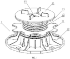
Fig.1 is an assembled structure schematic diagram of the present disclosure; -
Fig.2 is an exploded structure schematic diagram of the present disclosure; -
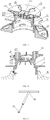
Fig. 3 is a sectional structural schematic diagram before adjusting the support plate and the screw; -
Fig. 4 is a sectional structural schematic diagram after adjusting the support plate and the screw; -
Fig. 5 is a structural schematic diagram of the wrench; -
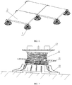
Fig. 6 is a use structural schematic diagram of the supporter; and -
Fig. 7 is a schematic diagram of using the supporter on a sloped ground surface. - As illustrated in
Figs. 1 and2 , a slope-adjustedsupporter 1 is provided, comprising abase 10, asupport plate 13, and a height adjustment part disposed between thebase 10 and thesupport plate 13 to adjust a height of the support plate through thread fit, thesupport plate 13 being slidable relative to the height adjustment part. - Particularly, the height adjustment part comprises a
screw 12. To implement relative sliding between thesupport plate 13 and thescrew 12, arecessed arc surface 122 is provided at a top portion of the screw, aconvex arc surface 134 is provided at a bottom portion of the support plate, and the convexarc surface 134 is supported inside the recessedarc surface 122 to implement the relative sliding. - As illustrated in
Fig. 3 , before adjustment of thesupport plate 13 and thescrew 12, an upper plane of the support plate is parallel to a lower plane of the base. As illustrated inFigs. 4 and7 , after the supporter is placed on a sloped face, due to its own gravity or external force, an included angle between the upper plane of the support plate and the sloped face will change after theconvex arc surface 134 supported in therecessed arc face 122 has a relative slide, and the upper plane of the support plate may be calibrated to be horizontal through a level gauge. - As illustrated in
Fig. 2 , to facilitate adjusting the height of thescrew 12, a center of the support plate is provided with a through-hole 132, a center of the screw is provided with aconvex column 123 protruding above the recessed arc surface. The convex column functions to limit a movable range of the support plate and prevent the supporter from sliding off. A center of the convex column is provided with aplug hole 1231. As illustrated inFig. 5 , awrench 16 driving thescrew 12 to rotate may be inserted in theplug hole 1231. Thewrench 16 is in a T shape, a head portion of which has adrive head 161, thedrive head 161 being inserted into theplug hole 1231, rotation of thewrench 16 drives rotation of thescrew 12 to thereby implement height adjustment of thescrew 12. Of course, those skilled in the art may understand that thedrive head 161 and theplug hole 1231 may have a variety of shapes, e.g., an elongated bar shape adopted in this embodiment, or various kinds of polygonal shapes. - If the supporter is applied to a smooth ground, the
support plate 13 needs to be locked to limit sliding of thesupport plate 13; therefore, ananti-rotation plug 15 preventing relative rotation therebetween is disposed between thesupport plate 13 and thescrew 12.Catch positions 1232 are evenly distributed at an outer wall of the convex column along a peripheral direction. Theanti-rotation plug 15 is provided with acatch boss 152 for being caught in thecatch positions 1232 and aplug pin 151 for being plugged in theplug hole 1231, wherein positioning of theanti-rotation plug 15 is implemented by plugging theplug pin 151 into theplug hole 1231, such that theanti-rotation plug 15 will not be displaced freely; and thecatch boss 152 being caught in thecatch position 1232 achieves the objective of limiting the support plate from sliding. - As illustrated in
Fig. 6 , the present disclosure is mainly applied to support aground tile 2, wherein positioning convexribs 131 distributed in a cross shape are provided at a top face of the support plate around a center of the top face. Corners of the floor tile are positioned by the positioning convex ribs, which facilitates paving and positioning of the floor tile. The positioning convexribs 131 may be snapped or cut off. For example, when the floor tiles are completely paved for final finish, the positioning convexribs 131 may be removed. - As a further improvement to the present embodiment, a
rubber gasket 14 is provided on thesupport plate 13, for achieving sufficient contact between the floor tile and the supporter as well as a slide-proof. A wrench via-hole 141 is provided at a center of the rubber gasket for thewrench 16 to pass through to thereby adjust rotation of thescrew 12. Of course, when theanti-rotation plug 15 is provided, it is also available for theanti-rotation plug 15 to pass through. Moreover, a bar-shaped hole 142 for the positioning convexribs 131 to pass through is provided at therubber gasket 14 surrounding the wrench via-hole. - Further, a material-saving
groove 133 is opened in the upper plane of the support plate. The material-saving groove is disposed to correspond to a bottom portion convex arc surface of the support plate, which may reduce consumption of the material, reduce weight, and lower cost, without affecting the strength of the support plate per se. - In this embodiment, the height adjustment part further comprises an adjusting
disc 11 having ascrew part 111. A center of the adjusting disc is hollow and provided with an inner thread fitted to thescrew 12, thebase 10 is provided with a threadedsleeve part 101 having an inner thread, the inner thread of the threaded sleeve part being fitted with the external thread of the screw part. In this way, height may be adjusted through thread fitting between the adjustingdisc 11 and thescrew 12 and between the adjustingdisc 11 and thebase 10. Particularly, thewrench 16 drives thescrew 12 to rotate, for adjusting a relative height between thescrew 12 and the adjustingdisc 11, while the relative height between the adjustingdisc 11 and thebase 10 is adjusted manually; therefore, provision of both of the adjustingdisc 11 and thescrew 12 may expand a height adjustment scope of the supporter. - The
screw sleeve part 101 of the base is disposed on abase plate 102. To secure the supporter, afixing hole 1021 for a screw to penetrate through is provided on thebase plate 102 so as to fix the base plate. A reinforcingrib 103 is provided between the threadedsleeve part 101 and thebase plate 102. - In the present disclosure, the terms "upper" and "lower" are intended to describe the positions of respective parts of the present disclosure with the use states in the figures as examples, which shall not be construed as limitations to the present disclosure.
- Besides the preferred embodiments above, the present disclosure further has other embodiments. Those skilled in the art may make various alterations and transformations based on the present disclosure, which should all fall into the scope defined by the appended claims of the present disclosure without departing from the spirit of the present disclosure.
Claims (7)
- A slope-adjustable supporter, comprising:a base,a support plate, anda height-adjusting part that is disposed between the base and the support plate to adjust a height of the support plate through thread fit, wherein:a top portion of the height-adjusting part is provided with a recessed arc surface;a bottom portion of the support plate is provided with a convex arc surface; andthe convex arc surface is supported inside the recessed arc surface and is slidable relative to the recessed arc surface.
- The slope-adjustable supporter according to claim 1, wherein:
the height-adjusting part comprises a screw having the recessed arc surface, a center of the support plate being provided with a through-hole, a center of the screw being provided with a convex column protruding above the recessed arc surface, a center of the convex column being provided with a plug hole into which a wrench driving the screw to rotate is insertable. - The slope-adjustable supporter according to claim 2, wherein an anti-rotation plug preventing a relative rotation is disposed between the support plate and the screw.
- The slope-adjustable supporter according to claim 3, wherein catch positions are evenly distributed at an outer wall of the convex column along a peripheral direction, the anti-rotation plug is provided with catch bosses for being caught into the catch positions, and the anti-rotation plug is provided with a plug pin for being plugged into the plug hole.
- The slope-adjustable supporter according to any one of claims 1∼4, wherein positioning convex ribs distributed in a cross shape are provided at a top face of the support plate around a center of the top face.
- The slope-adjustable supporter according to claim 5, wherein a rubber gasket is provided on the support plate.
- The slope-adjustable supporter according to claim 5, wherein a material-saving recessed groove is opened in an upper plane of the support plate.
Applications Claiming Priority (1)
| Application Number | Priority Date | Filing Date | Title |
|---|---|---|---|
| CN201720798900.4U CN206917190U (en) | 2017-07-04 | 2017-07-04 | A kind of adjustable slope eyelid retractor |
Publications (1)
| Publication Number | Publication Date |
|---|---|
| EP3425134A1 true EP3425134A1 (en) | 2019-01-09 |
Family
ID=61335423
Family Applications (1)
| Application Number | Title | Priority Date | Filing Date |
|---|---|---|---|
| EP18177319.3A Withdrawn EP3425134A1 (en) | 2017-07-04 | 2018-06-12 | Slope-adjustable supporter |
Country Status (3)
| Country | Link |
|---|---|
| EP (1) | EP3425134A1 (en) |
| CN (1) | CN206917190U (en) |
| DE (1) | DE202018006285U1 (en) |
Cited By (10)
| Publication number | Priority date | Publication date | Assignee | Title |
|---|---|---|---|---|
| CN109826077A (en) * | 2019-01-29 | 2019-05-31 | 湖州新峰木塑复合材料有限公司 | An adjustable slope supporter with convenient assembly and disassembly |
| EP3733994A1 (en) * | 2019-05-03 | 2020-11-04 | Profilpas S.p.A. | Universal support for raised floors |
| CN112064972A (en) * | 2020-09-25 | 2020-12-11 | 浙江亚厦装饰股份有限公司 | Stone plastic substrate overhead structure |
| GB2586479A (en) * | 2019-08-20 | 2021-02-24 | Elmdene Group Ltd | A device for supporting a joist or beam |
| CN114457969A (en) * | 2021-12-15 | 2022-05-10 | 浙江亚厦装饰股份有限公司 | Height adjusting assembly |
| CN114717898A (en) * | 2022-04-25 | 2022-07-08 | 交通运输部公路科学研究所 | Concrete pavement slab positioning device and method for airport assembly type runway |
| IT202200005153A1 (en) * | 2022-03-16 | 2023-09-16 | Italprofili | Support device for a raised floor, particularly for outdoor use. |
| WO2025065046A1 (en) * | 2023-09-25 | 2025-04-03 | Maximus Pedestal Systems Pty Ltd | Adaptable pedestal assembly and system for levelling construction surfaces |
| WO2025245768A1 (en) * | 2024-05-27 | 2025-12-04 | 无锡市浩秀建材科技有限公司 | Adjustable universal supporting device |
| EP4752307A1 (en) | 2024-11-26 | 2026-06-03 | Italprofili S.r.l. | Support device for a raised floor, particularly for outdoor use |
Families Citing this family (6)
| Publication number | Priority date | Publication date | Assignee | Title |
|---|---|---|---|---|
| IT201800006024A1 (en) * | 2018-06-05 | 2019-12-05 | SUPPORT FOR RAISED FLOORS | |
| US11299892B2 (en) | 2018-06-15 | 2022-04-12 | Profilitec S.P.A. Socio Unico | Head for a support of raised floors |
| CN109323085B (en) * | 2018-11-21 | 2020-12-11 | 威创集团股份有限公司 | A mobile component for LCD display |
| CN110617384A (en) * | 2019-09-23 | 2019-12-27 | 深圳市城市交通规划设计研究中心有限公司 | Universal support |
| CN113684992A (en) * | 2021-09-01 | 2021-11-23 | 广东玛格家居有限公司 | Overhead ground installation structure and construction method thereof |
| CN117188711A (en) * | 2023-10-12 | 2023-12-08 | 万华生态新家装(菏泽)有限公司 | Supporting device and method of laying decorative modules onto building surfaces |
Citations (4)
| Publication number | Priority date | Publication date | Assignee | Title |
|---|---|---|---|---|
| EP0483417A1 (en) * | 1990-10-25 | 1992-05-06 | Naka Corporation | Device for fixing floor panels |
| US20030070372A1 (en) * | 2001-10-17 | 2003-04-17 | Eterno Ivica S.P.A. | Support for raised floors with adjustable height and a swing system |
| US20040261329A1 (en) * | 2000-05-19 | 2004-12-30 | Kugler William E. | Apparatus for adjusting the elevation of a planar surface with threaded and non-threaded components |
| US8850753B2 (en) * | 2010-03-26 | 2014-10-07 | Ramin Tabibnia | Apparatus for establishing a paver surface over a subsurface |
-
2017
- 2017-07-04 CN CN201720798900.4U patent/CN206917190U/en active Active
-
2018
- 2018-06-12 EP EP18177319.3A patent/EP3425134A1/en not_active Withdrawn
- 2018-06-12 DE DE202018006285.5U patent/DE202018006285U1/en active Active
Patent Citations (4)
| Publication number | Priority date | Publication date | Assignee | Title |
|---|---|---|---|---|
| EP0483417A1 (en) * | 1990-10-25 | 1992-05-06 | Naka Corporation | Device for fixing floor panels |
| US20040261329A1 (en) * | 2000-05-19 | 2004-12-30 | Kugler William E. | Apparatus for adjusting the elevation of a planar surface with threaded and non-threaded components |
| US20030070372A1 (en) * | 2001-10-17 | 2003-04-17 | Eterno Ivica S.P.A. | Support for raised floors with adjustable height and a swing system |
| US8850753B2 (en) * | 2010-03-26 | 2014-10-07 | Ramin Tabibnia | Apparatus for establishing a paver surface over a subsurface |
Cited By (16)
| Publication number | Priority date | Publication date | Assignee | Title |
|---|---|---|---|---|
| CN109826077B (en) * | 2019-01-29 | 2023-10-24 | 湖州新峰木塑复合材料有限公司 | Conveniently-assembled and disassembled adjustable gradient support |
| CN109826077A (en) * | 2019-01-29 | 2019-05-31 | 湖州新峰木塑复合材料有限公司 | An adjustable slope supporter with convenient assembly and disassembly |
| EP3733994A1 (en) * | 2019-05-03 | 2020-11-04 | Profilpas S.p.A. | Universal support for raised floors |
| GB2586479A (en) * | 2019-08-20 | 2021-02-24 | Elmdene Group Ltd | A device for supporting a joist or beam |
| CN112064972A (en) * | 2020-09-25 | 2020-12-11 | 浙江亚厦装饰股份有限公司 | Stone plastic substrate overhead structure |
| CN114457969A (en) * | 2021-12-15 | 2022-05-10 | 浙江亚厦装饰股份有限公司 | Height adjusting assembly |
| IT202200005153A1 (en) * | 2022-03-16 | 2023-09-16 | Italprofili | Support device for a raised floor, particularly for outdoor use. |
| EP4249703A1 (en) | 2022-03-16 | 2023-09-27 | Italprofili S.r.l. | Device for supporting a raised floor |
| CN114717898A (en) * | 2022-04-25 | 2022-07-08 | 交通运输部公路科学研究所 | Concrete pavement slab positioning device and method for airport assembly type runway |
| CN114717898B (en) * | 2022-04-25 | 2023-12-01 | 交通运输部公路科学研究所 | Concrete pavement panel positioning device and method for airport assembly type runway |
| WO2025065046A1 (en) * | 2023-09-25 | 2025-04-03 | Maximus Pedestal Systems Pty Ltd | Adaptable pedestal assembly and system for levelling construction surfaces |
| WO2025065055A1 (en) * | 2023-09-25 | 2025-04-03 | Maximus Pedestal Systems Pty Ltd | Adaptable pedestal assembly and system for levelling construction surfaces |
| AU2024227304A1 (en) * | 2023-09-25 | 2025-04-10 | Maximus Pedestal Systems Pty Ltd | Adaptable pedestal assembly and system for levelling construction surfaces |
| AU2025283485B2 (en) * | 2023-09-25 | 2026-07-09 | Maximus Pedestal Systems Pty Ltd | Adaptable pedestal assembly and system for levelling construction surfaces |
| WO2025245768A1 (en) * | 2024-05-27 | 2025-12-04 | 无锡市浩秀建材科技有限公司 | Adjustable universal supporting device |
| EP4752307A1 (en) | 2024-11-26 | 2026-06-03 | Italprofili S.r.l. | Support device for a raised floor, particularly for outdoor use |
Also Published As
| Publication number | Publication date |
|---|---|
| CN206917190U (en) | 2018-01-23 |
| DE202018006285U1 (en) | 2019-11-14 |
Similar Documents
| Publication | Publication Date | Title |
|---|---|---|
| CN206917190U (en) | A kind of adjustable slope eyelid retractor | |
| US8850753B2 (en) | Apparatus for establishing a paver surface over a subsurface | |
| KR200446941Y1 (en) | Height adjustment stand for floorboard construction | |
| KR101513267B1 (en) | Apparatus for adjusting height of furniture | |
| KR102149107B1 (en) | Height adjustable furniture leg | |
| CN211548609U (en) | Wall brick supporting and leveling device | |
| CN204940818U (en) | Ceramic tile leveling device | |
| CN204071137U (en) | Laminate arrangement for adjusting height | |
| KR101354746B1 (en) | Leveling control screw | |
| CN103321382A (en) | Connecting piece and construction method for mounting building decorative stone panel | |
| CN110607890A (en) | A built-in height-adjustable foot cup structure for concrete elevated ground | |
| CN211548572U (en) | Built-in height-adjustable foot cup structure for concrete overhead ground | |
| CN211172905U (en) | Support device | |
| EP4121619B1 (en) | Tile installation tool and method | |
| CN210508420U (en) | Ground leveling device | |
| CA2822305C (en) | Improved apparatus for establishing a paver surface over a subsurface | |
| CN110273521A (en) | A kind of dry-hanging piece for stone | |
| CN204530898U (en) | A kind of nut turn nut moves the bracing or strutting arrangement of erecting bed lower flume | |
| KR101032138B1 (en) | Road boundary stone support device and construction method | |
| CN204703435U (en) | Building tile braced structures | |
| CN216690209U (en) | A supporter that prevents thread loosening | |
| CN104790480B (en) | Supporting device for nut rotation and screw movement mounting of underneath type sink | |
| CN101713163B (en) | Outdoor Raised Floor Adjustable Brackets | |
| CN224213736U (en) | Bathroom wallboard installation leveling device | |
| KR200454108Y1 (en) | Ball stand for sink |
Legal Events
| Date | Code | Title | Description |
|---|---|---|---|
| PUAI | Public reference made under article 153(3) epc to a published international application that has entered the european phase |
Free format text: ORIGINAL CODE: 0009012 |
|
| AK | Designated contracting states |
Kind code of ref document: A1 Designated state(s): AL AT BE BG CH CY CZ DE DK EE ES FI FR GB GR HR HU IE IS IT LI LT LU LV MC MK MT NL NO PL PT RO RS SE SI SK SM TR |
|
| AX | Request for extension of the european patent |
Extension state: BA ME |
|
| STAA | Information on the status of an ep patent application or granted ep patent |
Free format text: STATUS: THE APPLICATION IS DEEMED TO BE WITHDRAWN |
|
| 18D | Application deemed to be withdrawn |
Effective date: 20190710 |