EP3424790A1 - System and method for handling light source impairment - Google Patents
System and method for handling light source impairment Download PDFInfo
- Publication number
- EP3424790A1 EP3424790A1 EP17180036.0A EP17180036A EP3424790A1 EP 3424790 A1 EP3424790 A1 EP 3424790A1 EP 17180036 A EP17180036 A EP 17180036A EP 3424790 A1 EP3424790 A1 EP 3424790A1
- Authority
- EP
- European Patent Office
- Prior art keywords
- user
- light source
- vehicle
- eye
- impaired
- Prior art date
- Legal status (The legal status is an assumption and is not a legal conclusion. Google has not performed a legal analysis and makes no representation as to the accuracy of the status listed.)
- Granted
Links
Images


Classifications
-
- B—PERFORMING OPERATIONS; TRANSPORTING
- B60—VEHICLES IN GENERAL
- B60W—CONJOINT CONTROL OF VEHICLE SUB-UNITS OF DIFFERENT TYPE OR DIFFERENT FUNCTION; CONTROL SYSTEMS SPECIALLY ADAPTED FOR HYBRID VEHICLES; ROAD VEHICLE DRIVE CONTROL SYSTEMS FOR PURPOSES NOT RELATED TO THE CONTROL OF A PARTICULAR SUB-UNIT
- B60W50/00—Details of control systems for road vehicle drive control not related to the control of a particular sub-unit, e.g. process diagnostic or vehicle driver interfaces
- B60W50/08—Interaction between the driver and the control system
- B60W50/085—Changing the parameters of the control units, e.g. changing limit values, working points by control input
-
- B—PERFORMING OPERATIONS; TRANSPORTING
- B60—VEHICLES IN GENERAL
- B60W—CONJOINT CONTROL OF VEHICLE SUB-UNITS OF DIFFERENT TYPE OR DIFFERENT FUNCTION; CONTROL SYSTEMS SPECIALLY ADAPTED FOR HYBRID VEHICLES; ROAD VEHICLE DRIVE CONTROL SYSTEMS FOR PURPOSES NOT RELATED TO THE CONTROL OF A PARTICULAR SUB-UNIT
- B60W50/00—Details of control systems for road vehicle drive control not related to the control of a particular sub-unit, e.g. process diagnostic or vehicle driver interfaces
- B60W50/0098—Details of control systems ensuring comfort, safety or stability not otherwise provided for
-
- B—PERFORMING OPERATIONS; TRANSPORTING
- B60—VEHICLES IN GENERAL
- B60W—CONJOINT CONTROL OF VEHICLE SUB-UNITS OF DIFFERENT TYPE OR DIFFERENT FUNCTION; CONTROL SYSTEMS SPECIALLY ADAPTED FOR HYBRID VEHICLES; ROAD VEHICLE DRIVE CONTROL SYSTEMS FOR PURPOSES NOT RELATED TO THE CONTROL OF A PARTICULAR SUB-UNIT
- B60W30/00—Purposes of road vehicle drive control systems not related to the control of a particular sub-unit, e.g. of systems using conjoint control of vehicle sub-units
- B60W30/08—Active safety systems predicting or avoiding probable or impending collision or attempting to minimise its consequences
- B60W30/09—Taking automatic action to avoid collision, e.g. braking and steering
-
- B—PERFORMING OPERATIONS; TRANSPORTING
- B60—VEHICLES IN GENERAL
- B60W—CONJOINT CONTROL OF VEHICLE SUB-UNITS OF DIFFERENT TYPE OR DIFFERENT FUNCTION; CONTROL SYSTEMS SPECIALLY ADAPTED FOR HYBRID VEHICLES; ROAD VEHICLE DRIVE CONTROL SYSTEMS FOR PURPOSES NOT RELATED TO THE CONTROL OF A PARTICULAR SUB-UNIT
- B60W30/00—Purposes of road vehicle drive control systems not related to the control of a particular sub-unit, e.g. of systems using conjoint control of vehicle sub-units
- B60W30/10—Path keeping
- B60W30/12—Lane keeping
-
- B—PERFORMING OPERATIONS; TRANSPORTING
- B60—VEHICLES IN GENERAL
- B60W—CONJOINT CONTROL OF VEHICLE SUB-UNITS OF DIFFERENT TYPE OR DIFFERENT FUNCTION; CONTROL SYSTEMS SPECIALLY ADAPTED FOR HYBRID VEHICLES; ROAD VEHICLE DRIVE CONTROL SYSTEMS FOR PURPOSES NOT RELATED TO THE CONTROL OF A PARTICULAR SUB-UNIT
- B60W50/00—Details of control systems for road vehicle drive control not related to the control of a particular sub-unit, e.g. process diagnostic or vehicle driver interfaces
- B60W50/08—Interaction between the driver and the control system
- B60W50/12—Limiting control by the driver depending on vehicle state, e.g. interlocking means for the control input for preventing unsafe operation
-
- B—PERFORMING OPERATIONS; TRANSPORTING
- B60—VEHICLES IN GENERAL
- B60W—CONJOINT CONTROL OF VEHICLE SUB-UNITS OF DIFFERENT TYPE OR DIFFERENT FUNCTION; CONTROL SYSTEMS SPECIALLY ADAPTED FOR HYBRID VEHICLES; ROAD VEHICLE DRIVE CONTROL SYSTEMS FOR PURPOSES NOT RELATED TO THE CONTROL OF A PARTICULAR SUB-UNIT
- B60W60/00—Drive control systems specially adapted for autonomous road vehicles
- B60W60/005—Handover processes
- B60W60/0059—Estimation of the risk associated with autonomous or manual driving, e.g. situation too complex, sensor failure or driver incapacity
-
- G—PHYSICS
- G01—MEASURING; TESTING
- G01J—MEASUREMENT OF INTENSITY, VELOCITY, SPECTRAL CONTENT, POLARISATION, PHASE OR PULSE CHARACTERISTICS OF INFRARED, VISIBLE OR ULTRAVIOLET LIGHT; COLORIMETRY; RADIATION PYROMETRY
- G01J1/00—Photometry, e.g. photographic exposure meter
- G01J1/42—Photometry, e.g. photographic exposure meter using electric radiation detectors
-
- G—PHYSICS
- G06—COMPUTING OR CALCULATING; COUNTING
- G06V—IMAGE OR VIDEO RECOGNITION OR UNDERSTANDING
- G06V20/00—Scenes; Scene-specific elements
- G06V20/50—Context or environment of the image
- G06V20/59—Context or environment of the image inside of a vehicle, e.g. relating to seat occupancy, driver state or inner lighting conditions
-
- B—PERFORMING OPERATIONS; TRANSPORTING
- B60—VEHICLES IN GENERAL
- B60W—CONJOINT CONTROL OF VEHICLE SUB-UNITS OF DIFFERENT TYPE OR DIFFERENT FUNCTION; CONTROL SYSTEMS SPECIALLY ADAPTED FOR HYBRID VEHICLES; ROAD VEHICLE DRIVE CONTROL SYSTEMS FOR PURPOSES NOT RELATED TO THE CONTROL OF A PARTICULAR SUB-UNIT
- B60W2420/00—Indexing codes relating to the type of sensors based on the principle of their operation
- B60W2420/40—Photo, light or radio wave sensitive means, e.g. infrared sensors
- B60W2420/403—Image sensing, e.g. optical camera
-
- B—PERFORMING OPERATIONS; TRANSPORTING
- B60—VEHICLES IN GENERAL
- B60W—CONJOINT CONTROL OF VEHICLE SUB-UNITS OF DIFFERENT TYPE OR DIFFERENT FUNCTION; CONTROL SYSTEMS SPECIALLY ADAPTED FOR HYBRID VEHICLES; ROAD VEHICLE DRIVE CONTROL SYSTEMS FOR PURPOSES NOT RELATED TO THE CONTROL OF A PARTICULAR SUB-UNIT
- B60W2540/00—Input parameters relating to occupants
- B60W2540/22—Psychological state; Stress level or workload
-
- B—PERFORMING OPERATIONS; TRANSPORTING
- B60—VEHICLES IN GENERAL
- B60W—CONJOINT CONTROL OF VEHICLE SUB-UNITS OF DIFFERENT TYPE OR DIFFERENT FUNCTION; CONTROL SYSTEMS SPECIALLY ADAPTED FOR HYBRID VEHICLES; ROAD VEHICLE DRIVE CONTROL SYSTEMS FOR PURPOSES NOT RELATED TO THE CONTROL OF A PARTICULAR SUB-UNIT
- B60W2540/00—Input parameters relating to occupants
- B60W2540/221—Physiology, e.g. weight, heartbeat, health or special needs
-
- B—PERFORMING OPERATIONS; TRANSPORTING
- B60—VEHICLES IN GENERAL
- B60W—CONJOINT CONTROL OF VEHICLE SUB-UNITS OF DIFFERENT TYPE OR DIFFERENT FUNCTION; CONTROL SYSTEMS SPECIALLY ADAPTED FOR HYBRID VEHICLES; ROAD VEHICLE DRIVE CONTROL SYSTEMS FOR PURPOSES NOT RELATED TO THE CONTROL OF A PARTICULAR SUB-UNIT
- B60W2540/00—Input parameters relating to occupants
- B60W2540/225—Direction of gaze
-
- B—PERFORMING OPERATIONS; TRANSPORTING
- B60—VEHICLES IN GENERAL
- B60W—CONJOINT CONTROL OF VEHICLE SUB-UNITS OF DIFFERENT TYPE OR DIFFERENT FUNCTION; CONTROL SYSTEMS SPECIALLY ADAPTED FOR HYBRID VEHICLES; ROAD VEHICLE DRIVE CONTROL SYSTEMS FOR PURPOSES NOT RELATED TO THE CONTROL OF A PARTICULAR SUB-UNIT
- B60W2540/00—Input parameters relating to occupants
- B60W2540/229—Attention level, e.g. attentive to driving, reading or sleeping
-
- B—PERFORMING OPERATIONS; TRANSPORTING
- B60—VEHICLES IN GENERAL
- B60W—CONJOINT CONTROL OF VEHICLE SUB-UNITS OF DIFFERENT TYPE OR DIFFERENT FUNCTION; CONTROL SYSTEMS SPECIALLY ADAPTED FOR HYBRID VEHICLES; ROAD VEHICLE DRIVE CONTROL SYSTEMS FOR PURPOSES NOT RELATED TO THE CONTROL OF A PARTICULAR SUB-UNIT
- B60W2540/00—Input parameters relating to occupants
- B60W2540/26—Incapacity
-
- B—PERFORMING OPERATIONS; TRANSPORTING
- B60—VEHICLES IN GENERAL
- B60W—CONJOINT CONTROL OF VEHICLE SUB-UNITS OF DIFFERENT TYPE OR DIFFERENT FUNCTION; CONTROL SYSTEMS SPECIALLY ADAPTED FOR HYBRID VEHICLES; ROAD VEHICLE DRIVE CONTROL SYSTEMS FOR PURPOSES NOT RELATED TO THE CONTROL OF A PARTICULAR SUB-UNIT
- B60W2555/00—Input parameters relating to exterior conditions, not covered by groups B60W2552/00, B60W2554/00
- B60W2555/20—Ambient conditions, e.g. wind or rain
-
- B—PERFORMING OPERATIONS; TRANSPORTING
- B60—VEHICLES IN GENERAL
- B60W—CONJOINT CONTROL OF VEHICLE SUB-UNITS OF DIFFERENT TYPE OR DIFFERENT FUNCTION; CONTROL SYSTEMS SPECIALLY ADAPTED FOR HYBRID VEHICLES; ROAD VEHICLE DRIVE CONTROL SYSTEMS FOR PURPOSES NOT RELATED TO THE CONTROL OF A PARTICULAR SUB-UNIT
- B60W2710/00—Output or target parameters relating to a particular sub-units
- B60W2710/30—Auxiliary equipments
-
- G—PHYSICS
- G01—MEASURING; TESTING
- G01J—MEASUREMENT OF INTENSITY, VELOCITY, SPECTRAL CONTENT, POLARISATION, PHASE OR PULSE CHARACTERISTICS OF INFRARED, VISIBLE OR ULTRAVIOLET LIGHT; COLORIMETRY; RADIATION PYROMETRY
- G01J1/00—Photometry, e.g. photographic exposure meter
- G01J1/42—Photometry, e.g. photographic exposure meter using electric radiation detectors
- G01J2001/4266—Photometry, e.g. photographic exposure meter using electric radiation detectors for measuring solar light
Definitions
- a system may comprise an arrangement as shown in figure 5 .
- the system may be at least partly comprised in the vehicle 103.
- the system is further configured to, e.g. by means of a determining module 505, determine whether the user's 101 vision is impaired by the light source 105. The determining is done based on whether there is a line of sight between the light source 105 and the user's eye(s), and based on the intensity of the light at the user's eye(s).
- the determining module 505 may also be referred to as a determining unit, a determining means, a determining circuit, means for determining, etc.
- the determining module 505 may be the processor 503 of the system.
Landscapes
- Engineering & Computer Science (AREA)
- Automation & Control Theory (AREA)
- Transportation (AREA)
- Mechanical Engineering (AREA)
- Human Computer Interaction (AREA)
- General Physics & Mathematics (AREA)
- Physics & Mathematics (AREA)
- Multimedia (AREA)
- Theoretical Computer Science (AREA)
- Spectroscopy & Molecular Physics (AREA)
- Lighting Device Outwards From Vehicle And Optical Signal (AREA)
- Traffic Control Systems (AREA)
- Aviation & Aerospace Engineering (AREA)
- Radar, Positioning & Navigation (AREA)
- Remote Sensing (AREA)
Abstract
Description
- Embodiments herein relate generally to a system, a method, and a vehicle at least partly comprising the system. More particularly the embodiments herein relate to handling light source impairment.
- When being subject to bright light, humans may experience difficulty in seeing things. This may also be referred to as glare or dazzle. The bright light received may be perceived as uncomfortable by the person. Several car accidents are caused by a user that was distracted by the sun, oncoming headlights or other light sources. Some figures say that 2,575 accidents out of 108,211 are caused by dazzling sun. With active safety systems in the vehicles, several of these accidents are prevented today.
- If a user of the vehicle is dazzled by e.g. the sun, the sun can be blocked at the particular windscreen position where it is visible to the user. For example, the windscreen may be a smart windscreen where a selectable part can be darkened in order to block the sun at the particular position. Another counter measure may be to activate another suitable safety system that is deactivated.
- After a blinding glare is removed, an after-image remains on the eye's retina that creates a blind spot for the user. This phenomenon, known as the Troxler Effect, has been found to postpone user reaction time by up to 1.4 seconds.
- Therefore, there is a need to at least mitigate or solve the issue that users' vision are impaired by light sources in order to reduce the amount of accidents caused by this.
- An objective of embodiments herein is therefore to obviate at least one of the above disadvantages and to provide improved handling of light source impairment in a vehicle.
- According to a first aspect, the object is achieved by a method for handling light source impairment performed by a system at least partly comprised in a vehicle. The position of a user's eye(s) when the user is inside a vehicle is obtained. A position of a light source outside the vehicle and an intensity of light from the light source in relation to the position of the user's eye(s) are also obtained. Then, it is determined whether the user's vision is impaired by the light source. The determining is done based on whether there is a line of sight between the light source and the user's eye(s), and also based on the intensity of the light at the user's eye. A decision is taken by the vehicle whether at least one safety measure should be performed based on whether the user's vision is impaired by the light source.
- According to a second aspect, the object is achieved by a system at least partly comprised in a vehicle for handling light source impairment. The system is configured to obtain a position of a user's eye(s) when the user is inside a vehicle. The system is further configured to obtain a position of a light source outside the vehicle and an intensity of light from the light source in relation to the position of the user's eye(s). The system is also configured to determine whether the user's vision is impaired by the light source. Determination is done based on whether there is a line of sight between the light source and the user's eye(s), and based on the intensity of the light at the user's eye. The system is configured to determine whether at least one safety measure should be performed by the vehicle based on whether the user's vision is impaired by the light source.
- According to a third aspect, the object is achieved by a vehicle at least partly comprising the system according to the second aspect.
- Since it is determined whether the user's vision is impaired by the light source based on whether there is a line of sight between the light source and the user's eye(s), and based on the intensity of the light at the user's eye(s), it is possible to determine whether at least one safety measure should be performed by the vehicle. Thus handling of light source impairment in a vehicle is improved.
- Embodiments herein afford many advantages, of which a non-exhaustive list of examples follows:
- An advantage of the embodiments herein is that the vehicle can perform at least one safety measure if the user's vision is impaired by the light source in order to avoid accidents and to provide a comfortable ride.
- Another advantage of the embodiments is that by combining both the eye(s) position the light source position and light intensity, the decision regarding impairment is improved compared to using only one of the parameters.
- The embodiments herein are not limited to the features and advantages mentioned above. A person skilled in the art will recognize additional features and advantages upon reading the following detailed description.
- The embodiments herein will now be further described in more detail in the following detailed description by reference to the appended drawings illustrating the embodiments and in which:
- Fig. 1
- is a schematic drawing illustrating a vehicle.
- Fig. 2
- is a schematic drawing illustrating light source elevation.
- Fig. 3
- is a schematic drawing illustrating light source azimuth.
- Fig. 4
- is a flow chart illustrating embodiments of a method.
- Fig. 5
- is a schematic block diagram illustrating embodiments of a system.
- The drawings are not necessarily to scale and the dimensions of certain features may have been exaggerated for the sake of clarity. Emphasis is instead placed upon illustrating the principle of the embodiments herein.
-
Figure 1 illustrates auser 101 of avehicle 103. Theuser 101 is illustrated infigure 1 as to be located inside thevehicle 103. Thevehicle 103 may be any arbitrary vehicle, for instance a car, truck, lorry, van, bus, motorcycle etc. Thevehicle 103 may be at least partly autonomous or self-driven, it may be non-autonomous, or it may be completely autonomous etc. Thevehicle 103 has a windscreen which is at least partly transparent, and through which theuser 101 looks forward and through which it also can receive light from alight source 105. Thelight source 105 is located outside thevehicle 103. Thelight source 105 may be the sun, oncoming headlights from other vehicles, other light sources in the surroundings outside the vehicle 130 etc. - The
user 101 may be a driver of thevehicle 103 or he may be a passenger or occupant of thevehicle 103. Theuser 101 may also be referred to as an operator of thevehicle 103. -
Figure 1 also illustrates a coordinate system having an x and y axis. When the surface on which thevehicle 103 is positioned is flat, the x-axis follows the surface (e.g. the road) on which thevehicle 103 is positioned. Increasing x coordinates represent the forward moving direction of thevehicle 103. The y-axis is perpendicular to the x-axis. This coordinate system is also illustrated in some of the other figures. - The
vehicle 103 comprises one or moreuser monitoring devices 107 and one or more forward lookingdevices 109. Thesedevices - The
user monitoring device 107 is mounted inside and/or outside thevehicle 103 and in a position such that it can monitor (e.g. by filming, by taking pictures etc.) theuser 101, and in particular at one or both of the user's 101 eyes, or any other suitable point in relation to the eye(s), e.g. a point between the eyes. Theuser monitoring device 107 may be mounted for example on the steering wheel inside thevehicle 103, it may be mounted in the roof, it may be mounted inside or outside the windscreen etc. In case there are two or moreuser monitoring devices 107, the may be positioned at different positions in thevehicle 103 in order to monitor theuser 101 from different angles. α infigure 1 represents the recording angle of theuser monitoring device 107 with respect to the x-axis. - The forward looking
device 109 is in a position such that it can monitor at least what happens in the forward driving direction of thevehicle 103. The forward lookingdevice 109 may also be adapted to monitor at least part of what happens at the sides of thevehicle 103, e.g. when the forward looking device is a 109 wide angle camera. Thus, the forward lookingdevice 109 may be arranged to obtain data from any direction(s) with respect to thevehicle 103 and need to necessarily be permanently forward looking. The forward lookingdevice 109 may be mounted inside or outside thevehicle 103. The forward lookingdevice 109 may be mounted for example on the vehicle's grill, on the roof of thevehicle 103, inside or outside the windscreen etc. In case there are two or more forward lookingdevices 109, they may be mounted at different positions, for example one on the left side of the grill and the other on the right side of the grill. - In some embodiments, the
user monitoring device 107 and the forward lookingdevice 109 are co-located in one device, where one part of the device is adapted to monitor the user and another part of the device is adapted to look forward of thevehicle 103. - The forward looking
device 109 is adapted to detect at least one of the following parameters of the light source 105: - Light source position (Light source elevation and/or light source azimuth).
- Light source intensity.
-
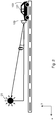
Figure 2 illustrates the light source altitude as detected by the forward lookingdevice 109, where the θ represents the elevation angle between the light and the horizon when it is recorded by the forward lookingdevice 109. In other words, θ represents how high the sun is above the surface on which thevehicle 103 is positioned. -
Figure 3 illustrates the light source azimuth that represents the horizontal angle between the light source and the direction of thevehicle 103 when it is recorded by the forward lookingdevice 109. In other words β infigure 3 represents the azimuth. - The light source elevation and the light source azimuth together provide the position of the
light source 105 in relation to thevehicle 103. - The light source intensity may be detected and measured in any suitable scale, e.g. lumen, W/m2 etc. Intensity may also be described as a measure of how bright the light from the
light source 105 is perceived by theuser 101. The light source intensity is associated with the distance between thelight source 105 and thevehicle 103 and itsuser 101. For example, alight source 105 which is far away from thevehicle 103 may have an intensity which is perceived by theuser 101 as lower compared to alight source 105 which is close to thevehicle 103. - As mentioned above, with the
user monitoring device 107, it is possible to detect the eye position in space, to detect atired user 101, based on e.g. eye opening size and blinking. However, with only theuser monitoring device 107, it is hard to distinguish between atired user 101 anduser 101 who is squinting because of alight source 105. By combining information about user's eye(s) position in space and the light source position and intensity, is it possible to determine if the user's 101 vision is impaired by thelight source 105. - With information about the light source's position and the user's eye(s) position it is possible to calculate exactly the light source location in regards to the user's eye(s). This may be done constantly, periodically or on demand. With information about that and the light intensity it is possible to determine if the
light source 105 is a disturbance or not to theuser 101. - Combining information about the light intensity and position with information about the user's eye(s) position it is possible to determine that the user's vision is impaired by the
light source 105 and perform at least one safety measure such as enabling the vehicles Lane Keeping Aid if not enabled, increase the parameter user reaction time that is used as input for Collision Mitigation by Braking and therefore have earlier interventions etc. - The method for handling
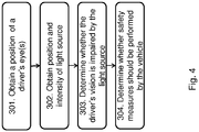
light source 105 impairment, according to some embodiments will now be described with reference to the flowchart infigure 4 . The method comprises at least one of the following steps, which steps may as well be carried out in another suitable order than described below. - The position of a user's 101 eye(s) when the
user 101 is inside avehicle 103 is obtained. The position may be of one of the user's eyes or both, or a position associated with the eye(s) (e.g. a position between the eyes). The position may be in relation to thevehicle 101. The position may be in the form of points in the xy-coordinate system illustrated infigures 1-3 . - The position of the user's 101 eye(s) may be obtained from a
user monitoring device 107 comprised in thevehicle 103. - A position of a
light source 105 outside thevehicle 103 is obtained, and also the intensity of light from thelight source 105 in relation to the position of the user's eye(s) is obtained. - The position of the
light source 105 may comprise at least one of azimuth and elevation information of thelight source 105 in relation to the position of the user's eye(s). - The position of the
light source 105 and the intensity of light from thelight source 105 may be obtained from a forward lookingdevice 109 comprised in thevehicle 103. - It is determined whether the user's 101 vision is impaired by the
light source 105. Determination is done based on whether there is a line of sight between thelight source 105 and the user's eye(s), and based on the intensity of the light at the user's eye(s). In order to determine this, the eye(s) position is compared with the light source position. It is determined whether there is a line of sight from thelight source 105 to the user's eye(s), i.e. whether electromagnetic waves can travel in a line from thelight source 105 to the user's eye(s). The line of sight may be a direct line of sight or a partly-direct line of sight. In addition, the light intensity at the user's eye(s) is compared to a threshold. If the light intensity is on or above a threshold, the light from thelight source 105 is so strong that it is deemed to be uncomfortable for theuser 101. If the light intensity is below the threshold, the light from the light source is not uncomfortable for theuser 101. - Table 1 below provides an overview of some example scenarios that may occur:
Table 1 Line of sight? Is light intensity on or above intensity threshold? Is user's vision impaired? Yes On or above Yes Yes Below Yes Yes Below No No On or above Yes No Below No - Based on whether the user's vision is impaired by the light source 105 (i.e. based on the decision in step 303), it is determined whether at least one safety measure should be performed by the
vehicle 103. For example, at least one safety measure should be performed if the user's 101 vision is impaired, and at least one safety measures should not be performed if the user's 101 vision is not impaired.Table 2 Line of sight? Is light intensity on or above intensity threshold? Is user's vision impaired? Perform safety measure? Yes On or above Yes Yes Yes Below Yes Yes Yes Below No No No On or above Yes Yes No Below No No - In another example, a degree of impairment may be evaluated in order to determine whether at least one safety measure should be performed, for example if the impairment is on, above or below an impairment threshold. Some example scenarios are provided in Table 3 below.
Table 3 Line of sight? Is light intensity on or above intensity threshold? Is user's vision impaired? Is impairment on, above or below threshold? Perform safety measures? Yes On or above Yes On or above Yes Yes Below Yes On or above Yes Yes Below No Below No No On or above Yes On or above Yes No Below No Below No - It may also be determined which at least one safety measure that should be performed, or which class the performed safety measure should belong to. Thus, the safety measures may be divided into classes, e.g. a first class and a second class. For example, the first class may comprise at least one safety measure that can be performed by the
vehicle 103 because the user's 101 vision is impaired to the degree that he is not able to see due to the dazzle. The second class may comprise at least one safety measure that can be performed because the user's vision is impaired to the degree that the light is only uncomfortable, but he is still able to see with his eye(s). Table 4 below provides an overview of some examples of whether or not to perform at least one safety measure, and the class of the measure.Table 4 Line of sight? Is light intensity on or above intensity threshold? Is user's vision impaired? Perform safety measure? Which safety measure? Yes On or above Yes Yes Class 1 Yes Below Yes Yes Class 1 Yes Below No Maybe Class 2 or no No On or above Yes Yes Class 1 No Below No Maybe Class 2 or no - The at least one safety measure comprises at least one of: enabling a lane keeping aid in the
vehicle 103, increasing a user reaction time parameter used by a collision mitigation system in thevehicle 103, and denying handing control of thevehicle 103 back to theuser 101 when thevehicle 103 is an autonomous vehicle. - To perform the method steps shown in
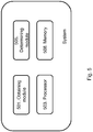
figure 4 for handlinglight source 105 impairment, a system may comprise an arrangement as shown infigure 5 . The system may be at least partly comprised in thevehicle 103. - The system is configured to, e.g. by means of an obtaining
module 501, obtain a position of a user's 101 eye(s) when theuser 101 is inside avehicle 103. The position of the user's 101 eye(s) may be obtained from auser monitoring device 107 comprised in thevehicle 103, for example by receiving position information. The obtainingmodule 501 may also be referred to as an obtaining unit, an obtaining means, an obtaining circuit, means for obtaining, etc. The obtainingmodule 501 may be aprocessor 503 of the system. - The system is further configured to, e.g. by means of the obtaining
module 501, obtain a position of alight source 105 outside thevehicle 103 and an intensity of light from thelight source 105 in relation to the position of the user's 101 eye(s). The position of thelight source 105 may comprise at least one of azimuth and/or elevation information of thelight source 105 in relation to the position of the user's eye(s). The position of thelight source 105 and the intensity of light from thelight source 105 may be obtained from a forward lookingdevice 109 comprised in thevehicle 103, e.g. by receiving position and intensity information from the forward lookingdevice 109. - The system is further configured to, e.g. by means of a determining
module 505, determine whether the user's 101 vision is impaired by thelight source 105. The determining is done based on whether there is a line of sight between thelight source 105 and the user's eye(s), and based on the intensity of the light at the user's eye(s). The determiningmodule 505 may also be referred to as a determining unit, a determining means, a determining circuit, means for determining, etc. The determiningmodule 505 may be theprocessor 503 of the system. - The system is further configured to, e.g. by means of the determining
module 505, determine whether at least one safety measure should be performed by thevehicle 103 based on whether the user's vision is impaired by thelight source 105. The at least one safety measure may comprise at least one of: enabling a lane keeping aid in thevehicle 103, increasing a user reaction time parameter used by a collision mitigation system in thevehicle 103, and denying handing control of the vehicle back to theuser 101 when thevehicle 103 is an autonomous vehicle. The at least one safety measure may be performed if the user's 101 vision is impaired by thelight source 105 to a degree which is equal to or above a threshold. The at least one safety measure may not be performed if the user's 101 vision is not impaired by thelight source 105 or if it is impaired by thelight source 105 to a degree below a threshold. - In some embodiments, the system comprises a
memory 508. Thememory 508 comprises instructions executable by theprocessor 503. Thememory 508 is arranged to be used to store data, position information, intensity information, safety measure information, match information, threshold values, time periods, configurations, schedulings, and applications to perform the methods herein when being executed in the system. - The present mechanism for handling
light source 105 impairment may be implemented through one or more processors, such as aprocessor 503 in the system depicted inFigure 5 , together with computer program code for performing the functions of the embodiments herein. The processor may be for example a Digital Signal Processor (DSP), Application Specific Integrated Circuit (ASIC) processor, Field-programmable gate array (FPGA) processor or microprocessor. The program code mentioned above may also be provided as a computer program product, for instance in the form of a data carrier carrying computer program code for performing the embodiments herein when being loaded into the system. One such carrier may be in the form of a CD ROM disc. It is however feasible with other data carriers such as a memory stick. The computer program code can furthermore be provided as pure program code on a server and downloaded to the system. - In some embodiments, a computer program may comprise instructions which, when executed on at least one processor, cause the at least one processor to carry out the method steps in
figure 3 . A carrier may comprise the computer program, and the carrier is one of an electronic signal, optical signal, radio signal or computer readable storage medium. - Summarized, when a
light source 105 such as the sun is standing low and in front of the user's 101 vision will be impaired by sun glare. Theuser 101 can also be dazzled by other strong light sources, like an oncoming vehicle at night with high beams on. By using a vehicle sensor that detects light source intensity and location in addition to auser monitoring device 107, it is possible to determine that the user's 101 vision is impaired by thelight source 105 and perform at least one safety measure. With this, it also possible to differ ifuser 101 is tired or squinting because of thelight source 105. The impairment may also be described as theuser 101 being "unavailable" due to the light. Sensors, such as theuser monitoring device 107 and the forward lookingdevice 109 are not impaired by the light. It is the user's vision that is impaired. The user's 101 unavailability is used to determine if theuser 101 is in the loop (can make correct decisions), if he is determined to be out of the loop due to being dazzled by the light source 106, at least one safety measure is performed. In addition, if thevehicle 103 is driving autonomously and control of thevehicle 103 has to be returned to theuser 101, the fact that if his vision is impaired by thelight source 105 may have to be considered as a risk. - The embodiments herein are not limited to the above described embodiments. Various alternatives, modifications and equivalents may be used. Therefore, the above embodiments should not be taken as limiting the scope of the embodiments, which is defined by the appending claims. A feature from one embodiment may be combined with one or more features of any other embodiment.
- It should be emphasized that the term "comprises/comprising" when used in this specification is taken to specify the presence of stated features, integers, steps or components, but does not preclude the presence or addition of one or more other features, integers, steps, components or groups thereof. It should also be noted that the words "a" or "an" preceding an element do not exclude the presence of a plurality of such elements. The terms "consisting of" or "consisting essentially of" may be used instead of the term comprising.
- The term "configured to" used herein may also be referred to as "arranged to", "adapted to", "capable of" or "operative to".
- It should also be emphasised that the steps of the methods defined in the appended claims may, without departing from the embodiments herein, be performed in another order than the order in which they appear in the claims.
Claims (9)
- A method for handling light source (105) impairment performed by a system at least partly comprised in a vehicle (103), the method comprising:obtaining (301) a position of a user's (101) eye(s) when the user (101) is inside the vehicle (103);obtaining (302) a position of a light source (105) outside the vehicle (103) and an intensity of light from the light source (105) in relation to the position of the user's (101) eye(s); anddetermining (303) whether the user's (101) vision is impaired by the light source (105), wherein the determining is done based on whether there is a line of sight between the light source (105) and the user's eye(s), and based on the intensity of light at the user's eye(s); anddetermining (304) whether at least one safety measure should be performed by the vehicle (103) based on whether the user's vision is impaired by the light source (105).
- The method according to claim 1, wherein the performed at least one safety measure comprise at least one of: enabling a lane keeping aid in the vehicle (103), increasing a user reaction time parameter used by a collision mitigation system in the vehicle (103), and denying handing control of the vehicle back to the user (101) when the vehicle (103) is an autonomous vehicle.
- The method according to any one of claims 1-2, wherein the at least one safety measure should be performed if the user's (101) vision is impaired by the light source (105) to a degree which is equal to or above a threshold.
- The method according to any one of claims 1-3, wherein the at least one safety measure is not performed if the user's (101) vision is not impaired by the light source (105) or if it is impaired by the light source (105) to a degree below a threshold.
- The method according to any one of claims 1-4, wherein the position of the light source (105) is obtained by obtaining at least one of azimuth and/or elevation information of the light source (105) in relation to the position of the user's (101) eye(s).
- The method according to any one of claims 1-5, wherein the position of the user's (101) eye(s) is obtained from a user monitoring device (107) comprised in the vehicle (103).
- The method according to any one of claims 1-6 wherein the position of the light source (105) and the intensity of light from the light source (105) are obtained from a forward looking device (109) comprised in the vehicle (103).
- A system at least partly comprised in a vehicle (103) for handling light source (105) impairment, the system being configured to:obtain a position of a user's (101) eye(s) when the user (101) is inside a vehicle (103);obtain a position of a light source (105) outside the vehicle (103) and an intensity of light from the light source (105) in relation to the position of the user's (101) eye; anddetermine whether the user's (101) vision is impaired by the light source (105), wherein determination is done based on whether there is a line of sight between the light source (105) and the user's eye(s), and based on the intensity of light at the user's eye(s); and todetermine whether at least one safety measure should be performed by the vehicle (103) based on whether the user's (101) vision is impaired by the light source (105).
- A vehicle (103) at least partly comprising the system according to claim 8.
Priority Applications (3)
| Application Number | Priority Date | Filing Date | Title |
|---|---|---|---|
| EP17180036.0A EP3424790B1 (en) | 2017-07-06 | 2017-07-06 | System and method for handling light source impairment |
| US16/020,098 US11014574B2 (en) | 2017-07-06 | 2018-06-27 | System and method for handling light source impairment |
| CN201810685608.0A CN109204323B (en) | 2017-07-06 | 2018-06-28 | System and method for dealing with light source damage |
Applications Claiming Priority (1)
| Application Number | Priority Date | Filing Date | Title |
|---|---|---|---|
| EP17180036.0A EP3424790B1 (en) | 2017-07-06 | 2017-07-06 | System and method for handling light source impairment |
Publications (2)
| Publication Number | Publication Date |
|---|---|
| EP3424790A1 true EP3424790A1 (en) | 2019-01-09 |
| EP3424790B1 EP3424790B1 (en) | 2020-09-09 |
Family
ID=59337463
Family Applications (1)
| Application Number | Title | Priority Date | Filing Date |
|---|---|---|---|
| EP17180036.0A Active EP3424790B1 (en) | 2017-07-06 | 2017-07-06 | System and method for handling light source impairment |
Country Status (3)
| Country | Link |
|---|---|
| US (1) | US11014574B2 (en) |
| EP (1) | EP3424790B1 (en) |
| CN (1) | CN109204323B (en) |
Families Citing this family (3)
| Publication number | Priority date | Publication date | Assignee | Title |
|---|---|---|---|---|
| US12441370B2 (en) * | 2020-03-30 | 2025-10-14 | Toyota Research Institute, Inc. | Driver dazzle mitigation systems and methods |
| US12498239B2 (en) * | 2022-06-16 | 2025-12-16 | At&T Intellectual Property I, L.P. | System for extended reality augmentation of situational navigation |
| DE102023116321A1 (en) | 2023-06-21 | 2024-12-24 | Bayerische Motoren Werke Aktiengesellschaft | Assistance system for supporting a driver of a vehicle during lateral guidance of the vehicle taking into account glare of the driver, vehicle and method |
Citations (4)
| Publication number | Priority date | Publication date | Assignee | Title |
|---|---|---|---|---|
| US20060140502A1 (en) * | 2004-12-25 | 2006-06-29 | Allan Tseng | Active visor system for eliminating glare in field-of-vision from mobile and transient light sources and reflective surfaces |
| US20090168185A1 (en) * | 2007-12-27 | 2009-07-02 | Motorola, Inc. | Electrochromic Windshield with Computer Vision Control |
| US20140091989A1 (en) * | 2009-04-02 | 2014-04-03 | GM Global Technology Operations LLC | Peripheral salient feature enhancement on full-windshield head-up display |
| WO2014195821A1 (en) * | 2013-06-04 | 2014-12-11 | Koninklijke Philips N.V. | A light monitoring system, a glare prevention system, a vehicle and a method of monitoring glare |
Family Cites Families (13)
| Publication number | Priority date | Publication date | Assignee | Title |
|---|---|---|---|---|
| US7167796B2 (en) * | 2000-03-09 | 2007-01-23 | Donnelly Corporation | Vehicle navigation system for use with a telematics system |
| US8169684B2 (en) * | 2002-09-30 | 2012-05-01 | Gentex Corporation | Vehicular rearview mirror elements and assemblies incorporating these elements |
| US9134585B2 (en) * | 2002-09-30 | 2015-09-15 | Gentex Corporation | Automotive rearview mirror with capacitive switches |
| CN100495274C (en) | 2007-07-19 | 2009-06-03 | 上海港机重工有限公司 | Automatic driving control method and system for large engineering vehicles |
| US8704653B2 (en) * | 2009-04-02 | 2014-04-22 | GM Global Technology Operations LLC | Enhanced road vision on full windshield head-up display |
| WO2011028686A1 (en) * | 2009-09-01 | 2011-03-10 | Magna Mirrors Of America, Inc. | Imaging and display system for vehicle |
| US9056584B2 (en) * | 2010-07-08 | 2015-06-16 | Gentex Corporation | Rearview assembly for a vehicle |
| CN101913356A (en) | 2010-08-22 | 2010-12-15 | 段杰 | Express drive protection system |
| US9073485B2 (en) | 2012-09-28 | 2015-07-07 | Hyundai Motor Company | System and method of controlling refraction in windshield based on driver ocular prescription |
| US9448449B2 (en) * | 2013-01-31 | 2016-09-20 | Venkataraman Ramanathan | Glare reduction system |
| CN204222597U (en) | 2014-08-03 | 2015-03-25 | 薛凌 | Car windscreen instrument desk sun screen |
| CN104637299A (en) | 2014-12-30 | 2015-05-20 | 东莞市高明企业服务有限公司 | A cloud-based safe driving control system and control method thereof |
| US11255663B2 (en) * | 2016-03-04 | 2022-02-22 | May Patents Ltd. | Method and apparatus for cooperative usage of multiple distance meters |
-
2017
- 2017-07-06 EP EP17180036.0A patent/EP3424790B1/en active Active
-
2018
- 2018-06-27 US US16/020,098 patent/US11014574B2/en active Active
- 2018-06-28 CN CN201810685608.0A patent/CN109204323B/en active Active
Patent Citations (4)
| Publication number | Priority date | Publication date | Assignee | Title |
|---|---|---|---|---|
| US20060140502A1 (en) * | 2004-12-25 | 2006-06-29 | Allan Tseng | Active visor system for eliminating glare in field-of-vision from mobile and transient light sources and reflective surfaces |
| US20090168185A1 (en) * | 2007-12-27 | 2009-07-02 | Motorola, Inc. | Electrochromic Windshield with Computer Vision Control |
| US20140091989A1 (en) * | 2009-04-02 | 2014-04-03 | GM Global Technology Operations LLC | Peripheral salient feature enhancement on full-windshield head-up display |
| WO2014195821A1 (en) * | 2013-06-04 | 2014-12-11 | Koninklijke Philips N.V. | A light monitoring system, a glare prevention system, a vehicle and a method of monitoring glare |
Also Published As
| Publication number | Publication date |
|---|---|
| US11014574B2 (en) | 2021-05-25 |
| US20190009792A1 (en) | 2019-01-10 |
| CN109204323A (en) | 2019-01-15 |
| EP3424790B1 (en) | 2020-09-09 |
| CN109204323B (en) | 2021-07-20 |
Similar Documents
| Publication | Publication Date | Title |
|---|---|---|
| US12600207B2 (en) | Vehicular vision system with glare reducing windshield | |
| EP2537709B1 (en) | Image processing apparatus and light distribution control method | |
| US10417512B2 (en) | Driver abnormality detection device and driver abnormality detection method | |
| US10538195B2 (en) | Adaptive lighting system of an off-road utility vehicle | |
| EP1683668B1 (en) | Variable transmissivity window system | |
| US7881839B2 (en) | Image acquisition and processing systems for vehicle equipment control | |
| CN106029416B (en) | Sunshading board | |
| US10399563B2 (en) | Driving support apparatus, driving support method, and computer program product | |
| JP6441360B2 (en) | Display system for displaying an image acquired by a camera system on a rearview mirror assembly of a vehicle | |
| US20100228435A1 (en) | Object detection system for vehicle | |
| JP5007818B2 (en) | Anti-glare device for vehicles | |
| US9398227B2 (en) | System and method for estimating daytime visibility | |
| JP2007276766A (en) | Monitoring device and method, recording medium, and program | |
| JP2016068791A (en) | Vehicle headlamp device | |
| EP3366522B1 (en) | Monitoring system, and vehicle mountable with monitoring system | |
| US11014574B2 (en) | System and method for handling light source impairment | |
| JP6187155B2 (en) | Gaze target estimation device | |
| WO2014195821A1 (en) | A light monitoring system, a glare prevention system, a vehicle and a method of monitoring glare | |
| JP5352266B2 (en) | Anti-glare device | |
| US9969332B1 (en) | Reduction of LED headlight flickering in electronic mirror applications | |
| JP5919110B2 (en) | Incident light analysis device, anti-glare control device, and incident light analysis method | |
| KR101655197B1 (en) | System and method for anti-glare of driver | |
| RU2369490C2 (en) | Multifunctional system for protecting eyes from blindness | |
| CN117698572A (en) | Rearview mirror far-reaching headlamp prompting method, device, equipment and storage medium | |
| US20160023607A1 (en) | Forward viewing camera configured to control outside electro-optic mirror |
Legal Events
| Date | Code | Title | Description |
|---|---|---|---|
| PUAI | Public reference made under article 153(3) epc to a published international application that has entered the european phase |
Free format text: ORIGINAL CODE: 0009012 |
|
| STAA | Information on the status of an ep patent application or granted ep patent |
Free format text: STATUS: THE APPLICATION HAS BEEN PUBLISHED |
|
| AK | Designated contracting states |
Kind code of ref document: A1 Designated state(s): AL AT BE BG CH CY CZ DE DK EE ES FI FR GB GR HR HU IE IS IT LI LT LU LV MC MK MT NL NO PL PT RO RS SE SI SK SM TR |
|
| AX | Request for extension of the european patent |
Extension state: BA ME |
|
| STAA | Information on the status of an ep patent application or granted ep patent |
Free format text: STATUS: REQUEST FOR EXAMINATION WAS MADE |
|
| 17P | Request for examination filed |
Effective date: 20190709 |
|
| RBV | Designated contracting states (corrected) |
Designated state(s): AL AT BE BG CH CY CZ DE DK EE ES FI FR GB GR HR HU IE IS IT LI LT LU LV MC MK MT NL NO PL PT RO RS SE SI SK SM TR |
|
| REG | Reference to a national code |
Ref country code: DE Ref legal event code: R079 Ref document number: 602017023142 Country of ref document: DE Free format text: PREVIOUS MAIN CLASS: B60W0030090000 Ipc: B60W0050120000 |
|
| RIC1 | Information provided on ipc code assigned before grant |
Ipc: B60W 30/12 20060101ALI20191218BHEP Ipc: B60W 50/12 20120101AFI20191218BHEP Ipc: B60W 30/09 20120101ALI20191218BHEP Ipc: G06K 9/00 20060101ALI20191218BHEP |
|
| GRAP | Despatch of communication of intention to grant a patent |
Free format text: ORIGINAL CODE: EPIDOSNIGR1 |
|
| STAA | Information on the status of an ep patent application or granted ep patent |
Free format text: STATUS: GRANT OF PATENT IS INTENDED |
|
| INTG | Intention to grant announced |
Effective date: 20200131 |
|
| GRAS | Grant fee paid |
Free format text: ORIGINAL CODE: EPIDOSNIGR3 |
|
| GRAA | (expected) grant |
Free format text: ORIGINAL CODE: 0009210 |
|
| STAA | Information on the status of an ep patent application or granted ep patent |
Free format text: STATUS: THE PATENT HAS BEEN GRANTED |
|
| AK | Designated contracting states |
Kind code of ref document: B1 Designated state(s): AL AT BE BG CH CY CZ DE DK EE ES FI FR GB GR HR HU IE IS IT LI LT LU LV MC MK MT NL NO PL PT RO RS SE SI SK SM TR |
|
| REG | Reference to a national code |
Ref country code: GB Ref legal event code: FG4D |
|
| REG | Reference to a national code |
Ref country code: AT Ref legal event code: REF Ref document number: 1311231 Country of ref document: AT Kind code of ref document: T Effective date: 20200915 Ref country code: CH Ref legal event code: EP |
|
| REG | Reference to a national code |
Ref country code: IE Ref legal event code: FG4D |
|
| REG | Reference to a national code |
Ref country code: DE Ref legal event code: R096 Ref document number: 602017023142 Country of ref document: DE |
|
| REG | Reference to a national code |
Ref country code: LT Ref legal event code: MG4D |
|
| PG25 | Lapsed in a contracting state [announced via postgrant information from national office to epo] |
Ref country code: NO Free format text: LAPSE BECAUSE OF FAILURE TO SUBMIT A TRANSLATION OF THE DESCRIPTION OR TO PAY THE FEE WITHIN THE PRESCRIBED TIME-LIMIT Effective date: 20201209 Ref country code: HR Free format text: LAPSE BECAUSE OF FAILURE TO SUBMIT A TRANSLATION OF THE DESCRIPTION OR TO PAY THE FEE WITHIN THE PRESCRIBED TIME-LIMIT Effective date: 20200909 Ref country code: SE Free format text: LAPSE BECAUSE OF FAILURE TO SUBMIT A TRANSLATION OF THE DESCRIPTION OR TO PAY THE FEE WITHIN THE PRESCRIBED TIME-LIMIT Effective date: 20200909 Ref country code: FI Free format text: LAPSE BECAUSE OF FAILURE TO SUBMIT A TRANSLATION OF THE DESCRIPTION OR TO PAY THE FEE WITHIN THE PRESCRIBED TIME-LIMIT Effective date: 20200909 Ref country code: GR Free format text: LAPSE BECAUSE OF FAILURE TO SUBMIT A TRANSLATION OF THE DESCRIPTION OR TO PAY THE FEE WITHIN THE PRESCRIBED TIME-LIMIT Effective date: 20201210 Ref country code: LT Free format text: LAPSE BECAUSE OF FAILURE TO SUBMIT A TRANSLATION OF THE DESCRIPTION OR TO PAY THE FEE WITHIN THE PRESCRIBED TIME-LIMIT Effective date: 20200909 Ref country code: BG Free format text: LAPSE BECAUSE OF FAILURE TO SUBMIT A TRANSLATION OF THE DESCRIPTION OR TO PAY THE FEE WITHIN THE PRESCRIBED TIME-LIMIT Effective date: 20201209 |
|
| REG | Reference to a national code |
Ref country code: AT Ref legal event code: MK05 Ref document number: 1311231 Country of ref document: AT Kind code of ref document: T Effective date: 20200909 |
|
| REG | Reference to a national code |
Ref country code: NL Ref legal event code: MP Effective date: 20200909 |
|
| PG25 | Lapsed in a contracting state [announced via postgrant information from national office to epo] |
Ref country code: LV Free format text: LAPSE BECAUSE OF FAILURE TO SUBMIT A TRANSLATION OF THE DESCRIPTION OR TO PAY THE FEE WITHIN THE PRESCRIBED TIME-LIMIT Effective date: 20200909 Ref country code: PL Free format text: LAPSE BECAUSE OF FAILURE TO SUBMIT A TRANSLATION OF THE DESCRIPTION OR TO PAY THE FEE WITHIN THE PRESCRIBED TIME-LIMIT Effective date: 20200909 Ref country code: RS Free format text: LAPSE BECAUSE OF FAILURE TO SUBMIT A TRANSLATION OF THE DESCRIPTION OR TO PAY THE FEE WITHIN THE PRESCRIBED TIME-LIMIT Effective date: 20200909 |
|
| PG25 | Lapsed in a contracting state [announced via postgrant information from national office to epo] |
Ref country code: CZ Free format text: LAPSE BECAUSE OF FAILURE TO SUBMIT A TRANSLATION OF THE DESCRIPTION OR TO PAY THE FEE WITHIN THE PRESCRIBED TIME-LIMIT Effective date: 20200909 Ref country code: PT Free format text: LAPSE BECAUSE OF FAILURE TO SUBMIT A TRANSLATION OF THE DESCRIPTION OR TO PAY THE FEE WITHIN THE PRESCRIBED TIME-LIMIT Effective date: 20210111 Ref country code: RO Free format text: LAPSE BECAUSE OF FAILURE TO SUBMIT A TRANSLATION OF THE DESCRIPTION OR TO PAY THE FEE WITHIN THE PRESCRIBED TIME-LIMIT Effective date: 20200909 Ref country code: SM Free format text: LAPSE BECAUSE OF FAILURE TO SUBMIT A TRANSLATION OF THE DESCRIPTION OR TO PAY THE FEE WITHIN THE PRESCRIBED TIME-LIMIT Effective date: 20200909 Ref country code: EE Free format text: LAPSE BECAUSE OF FAILURE TO SUBMIT A TRANSLATION OF THE DESCRIPTION OR TO PAY THE FEE WITHIN THE PRESCRIBED TIME-LIMIT Effective date: 20200909 |
|
| PG25 | Lapsed in a contracting state [announced via postgrant information from national office to epo] |
Ref country code: IS Free format text: LAPSE BECAUSE OF FAILURE TO SUBMIT A TRANSLATION OF THE DESCRIPTION OR TO PAY THE FEE WITHIN THE PRESCRIBED TIME-LIMIT Effective date: 20210109 Ref country code: AL Free format text: LAPSE BECAUSE OF FAILURE TO SUBMIT A TRANSLATION OF THE DESCRIPTION OR TO PAY THE FEE WITHIN THE PRESCRIBED TIME-LIMIT Effective date: 20200909 Ref country code: AT Free format text: LAPSE BECAUSE OF FAILURE TO SUBMIT A TRANSLATION OF THE DESCRIPTION OR TO PAY THE FEE WITHIN THE PRESCRIBED TIME-LIMIT Effective date: 20200909 Ref country code: ES Free format text: LAPSE BECAUSE OF FAILURE TO SUBMIT A TRANSLATION OF THE DESCRIPTION OR TO PAY THE FEE WITHIN THE PRESCRIBED TIME-LIMIT Effective date: 20200909 |
|
| REG | Reference to a national code |
Ref country code: DE Ref legal event code: R097 Ref document number: 602017023142 Country of ref document: DE |
|
| PG25 | Lapsed in a contracting state [announced via postgrant information from national office to epo] |
Ref country code: SK Free format text: LAPSE BECAUSE OF FAILURE TO SUBMIT A TRANSLATION OF THE DESCRIPTION OR TO PAY THE FEE WITHIN THE PRESCRIBED TIME-LIMIT Effective date: 20200909 |
|
| PLBE | No opposition filed within time limit |
Free format text: ORIGINAL CODE: 0009261 |
|
| STAA | Information on the status of an ep patent application or granted ep patent |
Free format text: STATUS: NO OPPOSITION FILED WITHIN TIME LIMIT |
|
| 26N | No opposition filed |
Effective date: 20210610 |
|
| PG25 | Lapsed in a contracting state [announced via postgrant information from national office to epo] |
Ref country code: SI Free format text: LAPSE BECAUSE OF FAILURE TO SUBMIT A TRANSLATION OF THE DESCRIPTION OR TO PAY THE FEE WITHIN THE PRESCRIBED TIME-LIMIT Effective date: 20200909 Ref country code: DK Free format text: LAPSE BECAUSE OF FAILURE TO SUBMIT A TRANSLATION OF THE DESCRIPTION OR TO PAY THE FEE WITHIN THE PRESCRIBED TIME-LIMIT Effective date: 20200909 |
|
| REG | Reference to a national code |
Ref country code: CH Ref legal event code: PL |
|
| GBPC | Gb: european patent ceased through non-payment of renewal fee |
Effective date: 20210706 |
|
| PG25 | Lapsed in a contracting state [announced via postgrant information from national office to epo] |
Ref country code: MC Free format text: LAPSE BECAUSE OF FAILURE TO SUBMIT A TRANSLATION OF THE DESCRIPTION OR TO PAY THE FEE WITHIN THE PRESCRIBED TIME-LIMIT Effective date: 20200909 |
|
| REG | Reference to a national code |
Ref country code: BE Ref legal event code: MM Effective date: 20210731 |
|
| PG25 | Lapsed in a contracting state [announced via postgrant information from national office to epo] |
Ref country code: LI Free format text: LAPSE BECAUSE OF NON-PAYMENT OF DUE FEES Effective date: 20210731 Ref country code: GB Free format text: LAPSE BECAUSE OF NON-PAYMENT OF DUE FEES Effective date: 20210706 Ref country code: CH Free format text: LAPSE BECAUSE OF NON-PAYMENT OF DUE FEES Effective date: 20210731 |
|
| PG25 | Lapsed in a contracting state [announced via postgrant information from national office to epo] |
Ref country code: LU Free format text: LAPSE BECAUSE OF NON-PAYMENT OF DUE FEES Effective date: 20210706 |
|
| PG25 | Lapsed in a contracting state [announced via postgrant information from national office to epo] |
Ref country code: IE Free format text: LAPSE BECAUSE OF NON-PAYMENT OF DUE FEES Effective date: 20210706 Ref country code: BE Free format text: LAPSE BECAUSE OF NON-PAYMENT OF DUE FEES Effective date: 20210731 |
|
| PG25 | Lapsed in a contracting state [announced via postgrant information from national office to epo] |
Ref country code: NL Free format text: LAPSE BECAUSE OF NON-PAYMENT OF DUE FEES Effective date: 20200923 Ref country code: CY Free format text: LAPSE BECAUSE OF FAILURE TO SUBMIT A TRANSLATION OF THE DESCRIPTION OR TO PAY THE FEE WITHIN THE PRESCRIBED TIME-LIMIT Effective date: 20200909 |
|
| PG25 | Lapsed in a contracting state [announced via postgrant information from national office to epo] |
Ref country code: HU Free format text: LAPSE BECAUSE OF FAILURE TO SUBMIT A TRANSLATION OF THE DESCRIPTION OR TO PAY THE FEE WITHIN THE PRESCRIBED TIME-LIMIT; INVALID AB INITIO Effective date: 20170706 |
|
| PG25 | Lapsed in a contracting state [announced via postgrant information from national office to epo] |
Ref country code: MK Free format text: LAPSE BECAUSE OF FAILURE TO SUBMIT A TRANSLATION OF THE DESCRIPTION OR TO PAY THE FEE WITHIN THE PRESCRIBED TIME-LIMIT Effective date: 20200909 |
|
| REG | Reference to a national code |
Ref country code: DE Ref legal event code: R081 Ref document number: 602017023142 Country of ref document: DE Owner name: POLESTAR PERFORMANCE AB, SE Free format text: FORMER OWNER: VOLVO CAR CORPORATION, GOETEBORG, SE |
|
| PG25 | Lapsed in a contracting state [announced via postgrant information from national office to epo] |
Ref country code: MT Free format text: LAPSE BECAUSE OF FAILURE TO SUBMIT A TRANSLATION OF THE DESCRIPTION OR TO PAY THE FEE WITHIN THE PRESCRIBED TIME-LIMIT Effective date: 20200909 |
|
| PGFP | Annual fee paid to national office [announced via postgrant information from national office to epo] |
Ref country code: FR Payment date: 20250521 Year of fee payment: 9 |
|
| REG | Reference to a national code |
Ref country code: DE Ref legal event code: R082 Ref document number: 602017023142 Country of ref document: DE |
|
| PGFP | Annual fee paid to national office [announced via postgrant information from national office to epo] |
Ref country code: DE Payment date: 20250618 Year of fee payment: 9 |
|
| PGFP | Annual fee paid to national office [announced via postgrant information from national office to epo] |
Ref country code: IT Payment date: 20250617 Year of fee payment: 9 |
|
| PG25 | Lapsed in a contracting state [announced via postgrant information from national office to epo] |
Ref country code: TR Free format text: LAPSE BECAUSE OF FAILURE TO SUBMIT A TRANSLATION OF THE DESCRIPTION OR TO PAY THE FEE WITHIN THE PRESCRIBED TIME-LIMIT Effective date: 20200909 |