EP3424701A1 - Fiber-reinforced resin material laminate and manufacturing method for same - Google Patents
Fiber-reinforced resin material laminate and manufacturing method for same Download PDFInfo
- Publication number
- EP3424701A1 EP3424701A1 EP17759995.8A EP17759995A EP3424701A1 EP 3424701 A1 EP3424701 A1 EP 3424701A1 EP 17759995 A EP17759995 A EP 17759995A EP 3424701 A1 EP3424701 A1 EP 3424701A1
- Authority
- EP
- European Patent Office
- Prior art keywords
- fiber
- resin material
- reinforced resin
- carrier sheet
- sheet
- Prior art date
- Legal status (The legal status is an assumption and is not a legal conclusion. Google has not performed a legal analysis and makes no representation as to the accuracy of the status listed.)
- Withdrawn
Links
- 229920005989 resin Polymers 0.000 title claims abstract description 188
- 239000011347 resin Substances 0.000 title claims abstract description 188
- 239000000463 material Substances 0.000 title claims abstract description 149
- 238000004519 manufacturing process Methods 0.000 title claims abstract description 41
- 239000000835 fiber Substances 0.000 claims abstract description 93
- 239000011159 matrix material Substances 0.000 claims abstract description 25
- 239000011342 resin composition Substances 0.000 claims abstract description 25
- 238000005470 impregnation Methods 0.000 claims abstract description 22
- 238000000034 method Methods 0.000 claims description 41
- 239000004820 Pressure-sensitive adhesive Substances 0.000 claims description 23
- 239000002243 precursor Substances 0.000 claims description 19
- 229920001296 polysiloxane Polymers 0.000 claims description 8
- 238000005422 blasting Methods 0.000 claims description 5
- 239000004576 sand Substances 0.000 claims description 4
- 238000005520 cutting process Methods 0.000 description 26
- 238000000465 moulding Methods 0.000 description 18
- PPBRXRYQALVLMV-UHFFFAOYSA-N Styrene Chemical compound C=CC1=CC=CC=C1 PPBRXRYQALVLMV-UHFFFAOYSA-N 0.000 description 10
- 239000011248 coating agent Substances 0.000 description 10
- 238000000576 coating method Methods 0.000 description 10
- 238000003860 storage Methods 0.000 description 8
- 229920000049 Carbon (fiber) Polymers 0.000 description 7
- 239000004917 carbon fiber Substances 0.000 description 7
- VNWKTOKETHGBQD-UHFFFAOYSA-N methane Chemical compound C VNWKTOKETHGBQD-UHFFFAOYSA-N 0.000 description 7
- 239000012783 reinforcing fiber Substances 0.000 description 7
- 238000003475 lamination Methods 0.000 description 6
- 239000003677 Sheet moulding compound Substances 0.000 description 5
- 239000004744 fabric Substances 0.000 description 5
- -1 polyethylene Polymers 0.000 description 5
- 229920001187 thermosetting polymer Polymers 0.000 description 5
- AZQWKYJCGOJGHM-UHFFFAOYSA-N 1,4-benzoquinone Chemical compound O=C1C=CC(=O)C=C1 AZQWKYJCGOJGHM-UHFFFAOYSA-N 0.000 description 4
- 239000004925 Acrylic resin Substances 0.000 description 4
- 239000004698 Polyethylene Substances 0.000 description 4
- 239000003795 chemical substances by application Substances 0.000 description 4
- 238000001723 curing Methods 0.000 description 4
- 229920000728 polyester Polymers 0.000 description 4
- 229920000573 polyethylene Polymers 0.000 description 4
- 230000001070 adhesive effect Effects 0.000 description 3
- 230000000694 effects Effects 0.000 description 3
- 229910052751 metal Inorganic materials 0.000 description 3
- 239000002184 metal Substances 0.000 description 3
- 239000003921 oil Substances 0.000 description 3
- 230000000704 physical effect Effects 0.000 description 3
- KCTAWXVAICEBSD-UHFFFAOYSA-N prop-2-enoyloxy prop-2-eneperoxoate Chemical compound C=CC(=O)OOOC(=O)C=C KCTAWXVAICEBSD-UHFFFAOYSA-N 0.000 description 3
- KDGNCLDCOVTOCS-UHFFFAOYSA-N (2-methylpropan-2-yl)oxy propan-2-yl carbonate Chemical compound CC(C)OC(=O)OOC(C)(C)C KDGNCLDCOVTOCS-UHFFFAOYSA-N 0.000 description 2
- XEEYBQQBJWHFJM-UHFFFAOYSA-N Iron Chemical compound [Fe] XEEYBQQBJWHFJM-UHFFFAOYSA-N 0.000 description 2
- 230000007850 degeneration Effects 0.000 description 2
- 239000003365 glass fiber Substances 0.000 description 2
- 239000012784 inorganic fiber Substances 0.000 description 2
- 230000001678 irradiating effect Effects 0.000 description 2
- 238000010030 laminating Methods 0.000 description 2
- 239000000203 mixture Substances 0.000 description 2
- 238000009751 slip forming Methods 0.000 description 2
- 239000003381 stabilizer Substances 0.000 description 2
- 239000000126 substance Substances 0.000 description 2
- 239000002562 thickening agent Substances 0.000 description 2
- 229920006337 unsaturated polyester resin Polymers 0.000 description 2
- 238000004804 winding Methods 0.000 description 2
- HSLFISVKRDQEBY-UHFFFAOYSA-N 1,1-bis(tert-butylperoxy)cyclohexane Chemical compound CC(C)(C)OOC1(OOC(C)(C)C)CCCCC1 HSLFISVKRDQEBY-UHFFFAOYSA-N 0.000 description 1
- 229940005561 1,4-benzoquinone Drugs 0.000 description 1
- ZOXJGFHDIHLPTG-UHFFFAOYSA-N Boron Chemical compound [B] ZOXJGFHDIHLPTG-UHFFFAOYSA-N 0.000 description 1
- OKTJSMMVPCPJKN-UHFFFAOYSA-N Carbon Chemical compound [C] OKTJSMMVPCPJKN-UHFFFAOYSA-N 0.000 description 1
- 239000004640 Melamine resin Substances 0.000 description 1
- 229920000877 Melamine resin Polymers 0.000 description 1
- 239000004952 Polyamide Substances 0.000 description 1
- 239000004743 Polypropylene Substances 0.000 description 1
- 239000004372 Polyvinyl alcohol Substances 0.000 description 1
- 229920000297 Rayon Polymers 0.000 description 1
- 229920000690 Tyvek Polymers 0.000 description 1
- 229920001807 Urea-formaldehyde Polymers 0.000 description 1
- 238000013006 addition curing Methods 0.000 description 1
- 239000000654 additive Substances 0.000 description 1
- PNEYBMLMFCGWSK-UHFFFAOYSA-N aluminium oxide Inorganic materials [O-2].[O-2].[O-2].[Al+3].[Al+3] PNEYBMLMFCGWSK-UHFFFAOYSA-N 0.000 description 1
- 238000013459 approach Methods 0.000 description 1
- 229920006231 aramid fiber Polymers 0.000 description 1
- CJDPJFRMHVXWPT-UHFFFAOYSA-N barium sulfide Chemical compound [S-2].[Ba+2] CJDPJFRMHVXWPT-UHFFFAOYSA-N 0.000 description 1
- HIFVAOIJYDXIJG-UHFFFAOYSA-N benzylbenzene;isocyanic acid Chemical class N=C=O.N=C=O.C=1C=CC=CC=1CC1=CC=CC=C1 HIFVAOIJYDXIJG-UHFFFAOYSA-N 0.000 description 1
- 230000000740 bleeding effect Effects 0.000 description 1
- 229910052796 boron Inorganic materials 0.000 description 1
- 238000007796 conventional method Methods 0.000 description 1
- 230000007423 decrease Effects 0.000 description 1
- 125000003700 epoxy group Chemical group 0.000 description 1
- 239000003822 epoxy resin Substances 0.000 description 1
- 239000005038 ethylene vinyl acetate Substances 0.000 description 1
- 230000001747 exhibiting effect Effects 0.000 description 1
- 229910002804 graphite Inorganic materials 0.000 description 1
- 239000010439 graphite Substances 0.000 description 1
- 150000003949 imides Chemical class 0.000 description 1
- 239000001023 inorganic pigment Substances 0.000 description 1
- 229910052742 iron Inorganic materials 0.000 description 1
- 239000005001 laminate film Substances 0.000 description 1
- 238000005259 measurement Methods 0.000 description 1
- 229920001778 nylon Polymers 0.000 description 1
- 239000012860 organic pigment Substances 0.000 description 1
- 239000005011 phenolic resin Substances 0.000 description 1
- 150000003014 phosphoric acid esters Chemical class 0.000 description 1
- 239000004033 plastic Substances 0.000 description 1
- 229920003023 plastic Polymers 0.000 description 1
- 229920001200 poly(ethylene-vinyl acetate) Polymers 0.000 description 1
- 229920002647 polyamide Polymers 0.000 description 1
- 229920000647 polyepoxide Polymers 0.000 description 1
- 229920006267 polyester film Polymers 0.000 description 1
- 229920000642 polymer Polymers 0.000 description 1
- 229920000098 polyolefin Polymers 0.000 description 1
- 229920001155 polypropylene Polymers 0.000 description 1
- 229920002451 polyvinyl alcohol Polymers 0.000 description 1
- 238000012805 post-processing Methods 0.000 description 1
- 238000012545 processing Methods 0.000 description 1
- 238000011160 research Methods 0.000 description 1
- HBMJWWWQQXIZIP-UHFFFAOYSA-N silicon carbide Chemical compound [Si+]#[C-] HBMJWWWQQXIZIP-UHFFFAOYSA-N 0.000 description 1
- 229910010271 silicon carbide Inorganic materials 0.000 description 1
- 229910001220 stainless steel Inorganic materials 0.000 description 1
- 239000010935 stainless steel Substances 0.000 description 1
- 238000012360 testing method Methods 0.000 description 1
- 229920002803 thermoplastic polyurethane Polymers 0.000 description 1
- UONOETXJSWQNOL-UHFFFAOYSA-N tungsten carbide Chemical compound [W+]#[C-] UONOETXJSWQNOL-UHFFFAOYSA-N 0.000 description 1
- 239000002699 waste material Substances 0.000 description 1
Images


Classifications
-
- B—PERFORMING OPERATIONS; TRANSPORTING
- B32—LAYERED PRODUCTS
- B32B—LAYERED PRODUCTS, i.e. PRODUCTS BUILT-UP OF STRATA OF FLAT OR NON-FLAT, e.g. CELLULAR OR HONEYCOMB, FORM
- B32B7/00—Layered products characterised by the relation between layers; Layered products characterised by the relative orientation of features between layers, or by the relative values of a measurable parameter between layers, i.e. products comprising layers having different physical, chemical or physicochemical properties; Layered products characterised by the interconnection of layers
- B32B7/04—Interconnection of layers
- B32B7/06—Interconnection of layers permitting easy separation
-
- B—PERFORMING OPERATIONS; TRANSPORTING
- B32—LAYERED PRODUCTS
- B32B—LAYERED PRODUCTS, i.e. PRODUCTS BUILT-UP OF STRATA OF FLAT OR NON-FLAT, e.g. CELLULAR OR HONEYCOMB, FORM
- B32B27/00—Layered products comprising a layer of synthetic resin
- B32B27/18—Layered products comprising a layer of synthetic resin characterised by the use of special additives
- B32B27/20—Layered products comprising a layer of synthetic resin characterised by the use of special additives using fillers, pigments, thixotroping agents
-
- B—PERFORMING OPERATIONS; TRANSPORTING
- B29—WORKING OF PLASTICS; WORKING OF SUBSTANCES IN A PLASTIC STATE IN GENERAL
- B29B—PREPARATION OR PRETREATMENT OF THE MATERIAL TO BE SHAPED; MAKING GRANULES OR PREFORMS; RECOVERY OF PLASTICS OR OTHER CONSTITUENTS OF WASTE MATERIAL CONTAINING PLASTICS
- B29B15/00—Pretreatment of the material to be shaped, not covered by groups B29B7/00 - B29B13/00
- B29B15/08—Pretreatment of the material to be shaped, not covered by groups B29B7/00 - B29B13/00 of reinforcements or fillers
- B29B15/10—Coating or impregnating independently of the moulding or shaping step
- B29B15/12—Coating or impregnating independently of the moulding or shaping step of reinforcements of indefinite length
- B29B15/122—Coating or impregnating independently of the moulding or shaping step of reinforcements of indefinite length with a matrix in liquid form, e.g. as melt, solution or latex
-
- B—PERFORMING OPERATIONS; TRANSPORTING
- B32—LAYERED PRODUCTS
- B32B—LAYERED PRODUCTS, i.e. PRODUCTS BUILT-UP OF STRATA OF FLAT OR NON-FLAT, e.g. CELLULAR OR HONEYCOMB, FORM
- B32B27/00—Layered products comprising a layer of synthetic resin
- B32B27/06—Layered products comprising a layer of synthetic resin as the main or only constituent of a layer, which is next to another layer of the same or of a different material
- B32B27/08—Layered products comprising a layer of synthetic resin as the main or only constituent of a layer, which is next to another layer of the same or of a different material of synthetic resin
-
- B—PERFORMING OPERATIONS; TRANSPORTING
- B32—LAYERED PRODUCTS
- B32B—LAYERED PRODUCTS, i.e. PRODUCTS BUILT-UP OF STRATA OF FLAT OR NON-FLAT, e.g. CELLULAR OR HONEYCOMB, FORM
- B32B27/00—Layered products comprising a layer of synthetic resin
- B32B27/12—Layered products comprising a layer of synthetic resin next to a fibrous or filamentary layer
-
- B—PERFORMING OPERATIONS; TRANSPORTING
- B32—LAYERED PRODUCTS
- B32B—LAYERED PRODUCTS, i.e. PRODUCTS BUILT-UP OF STRATA OF FLAT OR NON-FLAT, e.g. CELLULAR OR HONEYCOMB, FORM
- B32B27/00—Layered products comprising a layer of synthetic resin
- B32B27/30—Layered products comprising a layer of synthetic resin comprising vinyl (co)polymers; comprising acrylic (co)polymers
- B32B27/306—Layered products comprising a layer of synthetic resin comprising vinyl (co)polymers; comprising acrylic (co)polymers comprising vinyl acetate or vinyl alcohol (co)polymers
-
- B—PERFORMING OPERATIONS; TRANSPORTING
- B32—LAYERED PRODUCTS
- B32B—LAYERED PRODUCTS, i.e. PRODUCTS BUILT-UP OF STRATA OF FLAT OR NON-FLAT, e.g. CELLULAR OR HONEYCOMB, FORM
- B32B27/00—Layered products comprising a layer of synthetic resin
- B32B27/32—Layered products comprising a layer of synthetic resin comprising polyolefins
-
- B—PERFORMING OPERATIONS; TRANSPORTING
- B32—LAYERED PRODUCTS
- B32B—LAYERED PRODUCTS, i.e. PRODUCTS BUILT-UP OF STRATA OF FLAT OR NON-FLAT, e.g. CELLULAR OR HONEYCOMB, FORM
- B32B27/00—Layered products comprising a layer of synthetic resin
- B32B27/34—Layered products comprising a layer of synthetic resin comprising polyamides
-
- B—PERFORMING OPERATIONS; TRANSPORTING
- B32—LAYERED PRODUCTS
- B32B—LAYERED PRODUCTS, i.e. PRODUCTS BUILT-UP OF STRATA OF FLAT OR NON-FLAT, e.g. CELLULAR OR HONEYCOMB, FORM
- B32B3/00—Layered products comprising a layer with external or internal discontinuities or unevennesses, or a layer of non-planar shape; Layered products comprising a layer having particular features of form
- B32B3/02—Layered products comprising a layer with external or internal discontinuities or unevennesses, or a layer of non-planar shape; Layered products comprising a layer having particular features of form characterised by features of form at particular places, e.g. in edge regions
- B32B3/04—Layered products comprising a layer with external or internal discontinuities or unevennesses, or a layer of non-planar shape; Layered products comprising a layer having particular features of form characterised by features of form at particular places, e.g. in edge regions characterised by at least one layer folded at the edge, e.g. over another layer ; characterised by at least one layer enveloping or enclosing a material
-
- B—PERFORMING OPERATIONS; TRANSPORTING
- B32—LAYERED PRODUCTS
- B32B—LAYERED PRODUCTS, i.e. PRODUCTS BUILT-UP OF STRATA OF FLAT OR NON-FLAT, e.g. CELLULAR OR HONEYCOMB, FORM
- B32B37/00—Methods or apparatus for laminating, e.g. by curing or by ultrasonic bonding
- B32B37/14—Methods or apparatus for laminating, e.g. by curing or by ultrasonic bonding characterised by the properties of the layers
- B32B37/15—Methods or apparatus for laminating, e.g. by curing or by ultrasonic bonding characterised by the properties of the layers with at least one layer being manufactured and immediately laminated before reaching its stable state, e.g. in which a layer is extruded and laminated while in semi-molten state
-
- B—PERFORMING OPERATIONS; TRANSPORTING
- B32—LAYERED PRODUCTS
- B32B—LAYERED PRODUCTS, i.e. PRODUCTS BUILT-UP OF STRATA OF FLAT OR NON-FLAT, e.g. CELLULAR OR HONEYCOMB, FORM
- B32B38/00—Ancillary operations in connection with laminating processes
- B32B38/0012—Mechanical treatment, e.g. roughening, deforming, stretching
-
- B—PERFORMING OPERATIONS; TRANSPORTING
- B32—LAYERED PRODUCTS
- B32B—LAYERED PRODUCTS, i.e. PRODUCTS BUILT-UP OF STRATA OF FLAT OR NON-FLAT, e.g. CELLULAR OR HONEYCOMB, FORM
- B32B38/00—Ancillary operations in connection with laminating processes
- B32B38/18—Handling of layers or the laminate
- B32B38/1808—Handling of layers or the laminate characterised by the laying up of the layers
-
- B—PERFORMING OPERATIONS; TRANSPORTING
- B32—LAYERED PRODUCTS
- B32B—LAYERED PRODUCTS, i.e. PRODUCTS BUILT-UP OF STRATA OF FLAT OR NON-FLAT, e.g. CELLULAR OR HONEYCOMB, FORM
- B32B5/00—Layered products characterised by the non- homogeneity or physical structure, i.e. comprising a fibrous, filamentary, particulate or foam layer; Layered products characterised by having a layer differing constitutionally or physically in different parts
- B32B5/02—Layered products characterised by the non- homogeneity or physical structure, i.e. comprising a fibrous, filamentary, particulate or foam layer; Layered products characterised by having a layer differing constitutionally or physically in different parts characterised by structural features of a fibrous or filamentary layer
-
- B—PERFORMING OPERATIONS; TRANSPORTING
- B32—LAYERED PRODUCTS
- B32B—LAYERED PRODUCTS, i.e. PRODUCTS BUILT-UP OF STRATA OF FLAT OR NON-FLAT, e.g. CELLULAR OR HONEYCOMB, FORM
- B32B5/00—Layered products characterised by the non- homogeneity or physical structure, i.e. comprising a fibrous, filamentary, particulate or foam layer; Layered products characterised by having a layer differing constitutionally or physically in different parts
- B32B5/02—Layered products characterised by the non- homogeneity or physical structure, i.e. comprising a fibrous, filamentary, particulate or foam layer; Layered products characterised by having a layer differing constitutionally or physically in different parts characterised by structural features of a fibrous or filamentary layer
- B32B5/08—Layered products characterised by the non- homogeneity or physical structure, i.e. comprising a fibrous, filamentary, particulate or foam layer; Layered products characterised by having a layer differing constitutionally or physically in different parts characterised by structural features of a fibrous or filamentary layer the fibres or filaments of a layer being of different substances, e.g. conjugate fibres, mixture of different fibres
-
- B—PERFORMING OPERATIONS; TRANSPORTING
- B32—LAYERED PRODUCTS
- B32B—LAYERED PRODUCTS, i.e. PRODUCTS BUILT-UP OF STRATA OF FLAT OR NON-FLAT, e.g. CELLULAR OR HONEYCOMB, FORM
- B32B5/00—Layered products characterised by the non- homogeneity or physical structure, i.e. comprising a fibrous, filamentary, particulate or foam layer; Layered products characterised by having a layer differing constitutionally or physically in different parts
- B32B5/22—Layered products characterised by the non- homogeneity or physical structure, i.e. comprising a fibrous, filamentary, particulate or foam layer; Layered products characterised by having a layer differing constitutionally or physically in different parts characterised by the presence of two or more layers which are next to each other and are fibrous, filamentary, formed of particles or foamed
- B32B5/24—Layered products characterised by the non- homogeneity or physical structure, i.e. comprising a fibrous, filamentary, particulate or foam layer; Layered products characterised by having a layer differing constitutionally or physically in different parts characterised by the presence of two or more layers which are next to each other and are fibrous, filamentary, formed of particles or foamed one layer being a fibrous or filamentary layer
- B32B5/28—Layered products characterised by the non- homogeneity or physical structure, i.e. comprising a fibrous, filamentary, particulate or foam layer; Layered products characterised by having a layer differing constitutionally or physically in different parts characterised by the presence of two or more layers which are next to each other and are fibrous, filamentary, formed of particles or foamed one layer being a fibrous or filamentary layer impregnated with or embedded in a plastic substance
-
- B—PERFORMING OPERATIONS; TRANSPORTING
- B32—LAYERED PRODUCTS
- B32B—LAYERED PRODUCTS, i.e. PRODUCTS BUILT-UP OF STRATA OF FLAT OR NON-FLAT, e.g. CELLULAR OR HONEYCOMB, FORM
- B32B38/00—Ancillary operations in connection with laminating processes
- B32B38/0012—Mechanical treatment, e.g. roughening, deforming, stretching
- B32B2038/002—Sandblasting
-
- B—PERFORMING OPERATIONS; TRANSPORTING
- B32—LAYERED PRODUCTS
- B32B—LAYERED PRODUCTS, i.e. PRODUCTS BUILT-UP OF STRATA OF FLAT OR NON-FLAT, e.g. CELLULAR OR HONEYCOMB, FORM
- B32B2250/00—Layers arrangement
- B32B2250/40—Symmetrical or sandwich layers, e.g. ABA, ABCBA, ABCCBA
-
- B—PERFORMING OPERATIONS; TRANSPORTING
- B32—LAYERED PRODUCTS
- B32B—LAYERED PRODUCTS, i.e. PRODUCTS BUILT-UP OF STRATA OF FLAT OR NON-FLAT, e.g. CELLULAR OR HONEYCOMB, FORM
- B32B2250/00—Layers arrangement
- B32B2250/44—Number of layers variable across the laminate
-
- B—PERFORMING OPERATIONS; TRANSPORTING
- B32—LAYERED PRODUCTS
- B32B—LAYERED PRODUCTS, i.e. PRODUCTS BUILT-UP OF STRATA OF FLAT OR NON-FLAT, e.g. CELLULAR OR HONEYCOMB, FORM
- B32B2255/00—Coating on the layer surface
- B32B2255/10—Coating on the layer surface on synthetic resin layer or on natural or synthetic rubber layer
-
- B—PERFORMING OPERATIONS; TRANSPORTING
- B32—LAYERED PRODUCTS
- B32B—LAYERED PRODUCTS, i.e. PRODUCTS BUILT-UP OF STRATA OF FLAT OR NON-FLAT, e.g. CELLULAR OR HONEYCOMB, FORM
- B32B2255/00—Coating on the layer surface
- B32B2255/26—Polymeric coating
-
- B—PERFORMING OPERATIONS; TRANSPORTING
- B32—LAYERED PRODUCTS
- B32B—LAYERED PRODUCTS, i.e. PRODUCTS BUILT-UP OF STRATA OF FLAT OR NON-FLAT, e.g. CELLULAR OR HONEYCOMB, FORM
- B32B2260/00—Layered product comprising an impregnated, embedded, or bonded layer wherein the layer comprises an impregnation, embedding, or binder material
- B32B2260/02—Composition of the impregnated, bonded or embedded layer
- B32B2260/021—Fibrous or filamentary layer
-
- B—PERFORMING OPERATIONS; TRANSPORTING
- B32—LAYERED PRODUCTS
- B32B—LAYERED PRODUCTS, i.e. PRODUCTS BUILT-UP OF STRATA OF FLAT OR NON-FLAT, e.g. CELLULAR OR HONEYCOMB, FORM
- B32B2260/00—Layered product comprising an impregnated, embedded, or bonded layer wherein the layer comprises an impregnation, embedding, or binder material
- B32B2260/04—Impregnation, embedding, or binder material
- B32B2260/046—Synthetic resin
-
- B—PERFORMING OPERATIONS; TRANSPORTING
- B32—LAYERED PRODUCTS
- B32B—LAYERED PRODUCTS, i.e. PRODUCTS BUILT-UP OF STRATA OF FLAT OR NON-FLAT, e.g. CELLULAR OR HONEYCOMB, FORM
- B32B2262/00—Composition or structural features of fibres which form a fibrous or filamentary layer or are present as additives
- B32B2262/02—Synthetic macromolecular fibres
- B32B2262/0253—Polyolefin fibres
-
- B—PERFORMING OPERATIONS; TRANSPORTING
- B32—LAYERED PRODUCTS
- B32B—LAYERED PRODUCTS, i.e. PRODUCTS BUILT-UP OF STRATA OF FLAT OR NON-FLAT, e.g. CELLULAR OR HONEYCOMB, FORM
- B32B2262/00—Composition or structural features of fibres which form a fibrous or filamentary layer or are present as additives
- B32B2262/02—Synthetic macromolecular fibres
- B32B2262/0261—Polyamide fibres
-
- B—PERFORMING OPERATIONS; TRANSPORTING
- B32—LAYERED PRODUCTS
- B32B—LAYERED PRODUCTS, i.e. PRODUCTS BUILT-UP OF STRATA OF FLAT OR NON-FLAT, e.g. CELLULAR OR HONEYCOMB, FORM
- B32B2262/00—Composition or structural features of fibres which form a fibrous or filamentary layer or are present as additives
- B32B2262/02—Synthetic macromolecular fibres
- B32B2262/0261—Polyamide fibres
- B32B2262/0269—Aromatic polyamide fibres
-
- B—PERFORMING OPERATIONS; TRANSPORTING
- B32—LAYERED PRODUCTS
- B32B—LAYERED PRODUCTS, i.e. PRODUCTS BUILT-UP OF STRATA OF FLAT OR NON-FLAT, e.g. CELLULAR OR HONEYCOMB, FORM
- B32B2262/00—Composition or structural features of fibres which form a fibrous or filamentary layer or are present as additives
- B32B2262/02—Synthetic macromolecular fibres
- B32B2262/0276—Polyester fibres
-
- B—PERFORMING OPERATIONS; TRANSPORTING
- B32—LAYERED PRODUCTS
- B32B—LAYERED PRODUCTS, i.e. PRODUCTS BUILT-UP OF STRATA OF FLAT OR NON-FLAT, e.g. CELLULAR OR HONEYCOMB, FORM
- B32B2262/00—Composition or structural features of fibres which form a fibrous or filamentary layer or are present as additives
- B32B2262/10—Inorganic fibres
- B32B2262/101—Glass fibres
-
- B—PERFORMING OPERATIONS; TRANSPORTING
- B32—LAYERED PRODUCTS
- B32B—LAYERED PRODUCTS, i.e. PRODUCTS BUILT-UP OF STRATA OF FLAT OR NON-FLAT, e.g. CELLULAR OR HONEYCOMB, FORM
- B32B2262/00—Composition or structural features of fibres which form a fibrous or filamentary layer or are present as additives
- B32B2262/10—Inorganic fibres
- B32B2262/103—Metal fibres
-
- B—PERFORMING OPERATIONS; TRANSPORTING
- B32—LAYERED PRODUCTS
- B32B—LAYERED PRODUCTS, i.e. PRODUCTS BUILT-UP OF STRATA OF FLAT OR NON-FLAT, e.g. CELLULAR OR HONEYCOMB, FORM
- B32B2262/00—Composition or structural features of fibres which form a fibrous or filamentary layer or are present as additives
- B32B2262/10—Inorganic fibres
- B32B2262/105—Ceramic fibres
-
- B—PERFORMING OPERATIONS; TRANSPORTING
- B32—LAYERED PRODUCTS
- B32B—LAYERED PRODUCTS, i.e. PRODUCTS BUILT-UP OF STRATA OF FLAT OR NON-FLAT, e.g. CELLULAR OR HONEYCOMB, FORM
- B32B2262/00—Composition or structural features of fibres which form a fibrous or filamentary layer or are present as additives
- B32B2262/10—Inorganic fibres
- B32B2262/106—Carbon fibres, e.g. graphite fibres
-
- B—PERFORMING OPERATIONS; TRANSPORTING
- B32—LAYERED PRODUCTS
- B32B—LAYERED PRODUCTS, i.e. PRODUCTS BUILT-UP OF STRATA OF FLAT OR NON-FLAT, e.g. CELLULAR OR HONEYCOMB, FORM
- B32B2262/00—Composition or structural features of fibres which form a fibrous or filamentary layer or are present as additives
- B32B2262/14—Mixture of at least two fibres made of different materials
-
- B—PERFORMING OPERATIONS; TRANSPORTING
- B32—LAYERED PRODUCTS
- B32B—LAYERED PRODUCTS, i.e. PRODUCTS BUILT-UP OF STRATA OF FLAT OR NON-FLAT, e.g. CELLULAR OR HONEYCOMB, FORM
- B32B2305/00—Condition, form or state of the layers or laminate
- B32B2305/07—Parts immersed or impregnated in a matrix
- B32B2305/076—Prepregs
-
- B—PERFORMING OPERATIONS; TRANSPORTING
- B32—LAYERED PRODUCTS
- B32B—LAYERED PRODUCTS, i.e. PRODUCTS BUILT-UP OF STRATA OF FLAT OR NON-FLAT, e.g. CELLULAR OR HONEYCOMB, FORM
- B32B2307/00—Properties of the layers or laminate
- B32B2307/70—Other properties
- B32B2307/732—Dimensional properties
-
- B—PERFORMING OPERATIONS; TRANSPORTING
- B32—LAYERED PRODUCTS
- B32B—LAYERED PRODUCTS, i.e. PRODUCTS BUILT-UP OF STRATA OF FLAT OR NON-FLAT, e.g. CELLULAR OR HONEYCOMB, FORM
- B32B2405/00—Adhesive articles, e.g. adhesive tapes
-
- B—PERFORMING OPERATIONS; TRANSPORTING
- B32—LAYERED PRODUCTS
- B32B—LAYERED PRODUCTS, i.e. PRODUCTS BUILT-UP OF STRATA OF FLAT OR NON-FLAT, e.g. CELLULAR OR HONEYCOMB, FORM
- B32B37/00—Methods or apparatus for laminating, e.g. by curing or by ultrasonic bonding
- B32B37/10—Methods or apparatus for laminating, e.g. by curing or by ultrasonic bonding characterised by the pressing technique, e.g. using action of vacuum or fluid pressure
- B32B37/1027—Pressing using at least one press band
-
- B—PERFORMING OPERATIONS; TRANSPORTING
- B32—LAYERED PRODUCTS
- B32B—LAYERED PRODUCTS, i.e. PRODUCTS BUILT-UP OF STRATA OF FLAT OR NON-FLAT, e.g. CELLULAR OR HONEYCOMB, FORM
- B32B37/00—Methods or apparatus for laminating, e.g. by curing or by ultrasonic bonding
- B32B37/14—Methods or apparatus for laminating, e.g. by curing or by ultrasonic bonding characterised by the properties of the layers
- B32B37/24—Methods or apparatus for laminating, e.g. by curing or by ultrasonic bonding characterised by the properties of the layers with at least one layer not being coherent before laminating, e.g. made up from granular material sprinkled onto a substrate
-
- B—PERFORMING OPERATIONS; TRANSPORTING
- B32—LAYERED PRODUCTS
- B32B—LAYERED PRODUCTS, i.e. PRODUCTS BUILT-UP OF STRATA OF FLAT OR NON-FLAT, e.g. CELLULAR OR HONEYCOMB, FORM
- B32B38/00—Ancillary operations in connection with laminating processes
- B32B38/08—Impregnating
-
- C—CHEMISTRY; METALLURGY
- C08—ORGANIC MACROMOLECULAR COMPOUNDS; THEIR PREPARATION OR CHEMICAL WORKING-UP; COMPOSITIONS BASED THEREON
- C08J—WORKING-UP; GENERAL PROCESSES OF COMPOUNDING; AFTER-TREATMENT NOT COVERED BY SUBCLASSES C08B, C08C, C08F, C08G or C08H
- C08J5/00—Manufacture of articles or shaped materials containing macromolecular substances
- C08J5/04—Reinforcing macromolecular compounds with loose or coherent fibrous material
Definitions
- the present invention relates to a fiber-reinforced resin material laminate and a manufacturing method for the same.
- a sheet molding compound (SMC) exhibiting a property of easily flowing at the time of molding using a mold is widely used as a part having partially different wall thicknesses and an intermediate material of a fiber-reinforced resin material molded body having ribs, bosses, and the like.
- SMC is a fiber-reinforced resin material obtained, for example, by impregnating a sheet-shaped fiber bundle group formed of a plurality of chopped fiber bundles obtained by cutting a long reinforcing fiber such as a glass fiber or a carbon fiber into a predetermined length with a thermosetting resin such as an unsaturated polyester resin.
- a fiber-reinforced resin material molded body is obtained by appropriately cutting the fiber-reinforced resin material and then molding the cut fiber-reinforced resin material into a desired shape by using a mold.
- a long fiber-reinforced resin material is obtained by pressurizing a long material precursor in which a sheet-shaped fiber bundle group is sandwiched between a pair of resin sheets formed of a matrix resin composition from both sides and thus impregnating the sheet-shaped fiber bundle group with the matrix resin composition (for example, Patent Literature 1).
- Patent Literature 1 JP 01-249409 A
- An object of the present invention is to provide a fiber-reinforced resin material laminate which makes it possible to easily carry out steps before molding such as cutting of a fiber-reinforced resin material and a manufacturing method for the same.
- the present invention provides a fiber-reinforced resin material laminate and a manufacturing method for the same which have the following configurations.
- a fiber-reinforced resin material laminate of the present invention According to the method for manufacturing a fiber-reinforced resin material laminate of the present invention, a fiber-reinforced resin material laminate which makes it possible to easily carry out steps before molding such as cutting of a fiber-reinforced resin material is obtained.
- a fiber-reinforced resin material laminate 1 (hereinafter also simply referred to as the "laminate 1") of the present embodiment includes a long fiber-reinforced resin material 2 and a pair of long first carrier sheet 3 and a long second carrier sheet 4 which sandwich the fiber-reinforced resin material 2 as illustrated in Figs. 1 and 2 .
- the first carrier sheet 3 is disposed on the lower side of the fiber-reinforced resin material 2 and the second carrier sheet 4 is disposed on the upper side of the fiber-reinforced resin material 2.
- the widths of the first carrier sheet 3 and the second carrier sheet 4 are wider than the width of the fiber-reinforced resin material 2.
- the side edge portions of the first carrier sheet 3 and the second carrier sheet 4 are in close contact with each other on both sides in the width direction of the fiber-reinforced resin material 2.
- a mark portion 5 is provided on an outer surface 4a of the second carrier sheet 4.
- the fiber-reinforced resin material 2 is formed by impregnating a sheet-shaped fiber bundle group in which a plurality of fiber bundles are scattered in a sheet shape with a matrix resin composition.
- the reinforcing fiber which forms the fiber bundle is not particularly limited, and for example, an inorganic fiber, an organic fiber, a metal fiber, or a reinforcing fiber having a hybrid configuration in which these are combined can be used.
- Examples of the inorganic fiber may include a carbon fiber, a graphite fiber, a silicon carbide fiber, an alumina fiber, a tungsten carbide fiber, a boron fiber, and a glass fiber.
- Examples of the organic fiber may include an aramid fiber, a high density polyethylene fiber, other general nylon fibers, and a polyester fiber.
- Examples of the metal fiber may include fibers of stainless steel and iron, and a carbon fiber coated with a metal may also be used. Among these, a carbon fiber is preferable when mechanical properties such as strength of the fiber-reinforced resin material molded body are taken into consideration.
- the reinforcing fiber may be used singly or two or more kinds thereof may be used concurrently.
- the fiber length of the reinforcing fiber is preferably from 5 to 100 mm, more preferably from 10 to 75 mm, and still more preferably from 20 to 60 mm. It is likely to obtain a fiber-reinforced resin material molded body which exhibits excellent physical properties such as tensile strength and modulus of elasticity when the fiber length of the reinforcing fiber is the lower limit value or longer. The fiber-reinforced resin material is more likely to flow at the time of molding and thus molding is facilitated when the fiber length of the reinforcing fiber is the upper limit value or shorter.
- the average thickness of the fiber bundles is preferably from 0.01 to 0.5 mm, more preferably from 0.02 to 0.09 mm, and still more preferably from 0.025 to 0.07 mm. It is easy to impregnate the fiber bundle group with the matrix resin composition when the average thickness of the fiber bundles is the lower limit value or thicker. It is likely to obtain a fiber-reinforced resin material molded body which exhibits excellent physical properties such as tensile strength and modulus of elasticity when the average thickness of the fiber bundles is the upper limit value or thinner.
- the average thickness of the fiber bundles is measured by the following method.
- the fiber-reinforced resin material is heated in an electric furnace or the like to decompose the matrix resin composition and 10 fiber bundles are randomly selected from the residual fiber bundles.
- the thickness at three points of both end portions in the fiber axial direction and the center portion is measured by using a caliper, all of these measured values are averaged, and the value thus determined is taken as the average thickness.
- the average width of the fiber bundles is preferably from 1 to 50 mm, more preferably from 1.5 to 15 mm, and still more preferably from 2 to 8 mm.
- the fiber-reinforced resin material is more likely to flow at the time of molding and thus molding is facilitated when the average width of the fiber bundles is the lower limit value or wider. It is easy to obtain a fiber-reinforced resin material molded body which exhibits excellent physical properties such as tensile strength and modulus of elasticity when the average width of the fiber bundles is the upper limit value or narrower.
- the average width of the fiber bundles is measured by the following method. For each of the 10 fiber bundles obtained in the same manner as in the measurement of the average thickness, the width at three points of both end portions and center portion in the fiber axis direction is measured by using a caliper, all of these measured values are averaged, and the value thus determined is taken as the average width.
- a composition containing a thermosetting resin is preferable.
- thermosetting resin is not particularly limited, and examples thereof may include an epoxy resin, a phenol resin, an unsaturated polyester resin, a urethane resin, a urea resin, a melamine resin, and an imide resin. Among these, an acrylate resin having an epoxy group (epoxy acrylate resin) is preferable.
- the thermosetting resin may be used singly or two or more kinds thereof may be used concurrently.
- Additives such as a curing agent, an internal release agent, a thickening agent, and a stabilizer may be blended into the matrix resin composition if necessary.
- the pair of the first carrier sheet 3 and the second carrier sheet 4 are sheets which sandwich the fiber-reinforced resin material 2. At the time of molding, the first carrier sheet 3 and the second carrier sheet 4 are peeled off from the fiber-reinforced resin material 2.
- the material which forms the carrier sheet is not particularly limited as long as it can sandwich the fiber-reinforced resin material without degenerating the fiber-reinforced resin material, and examples thereof may include a film of a polyolefin such as polyethylene or polypropylene, a film of polyamide, polyvinyl alcohol, EVA, or the like, or a multilayer laminate film including these.
- the pair of carrier sheets may be the same as or different from each other.
- the thickness of the carrier sheet is preferably from 0.01 to 0.25 mm and more preferably from 0.04 to 0.1 mm. It is possible to suppress breakage of the carrier sheet during the manufacture of the fiber-reinforced resin material, particularly during the impregnation step when the thickness of the carrier sheet is the lower limit value or thicker. The post-processing such as cutting of the fiber-reinforced resin material laminate is facilitated when the thickness of the carrier sheet is the upper limit value or thinner.
- the thickness can be measured by using a micrometer.
- a mark portion 5 is provided on the outer surface 4a of the second carrier sheet 4 disposed on the upper side of the fiber-reinforced resin material 2.
- the mark portion 5 in this example has a band shape and is provided at the center portion in the width direction of the surface 4a of the second carrier sheet 4 in the length direction of the second carrier sheet 4.
- the mode in which the mark portion is provided on the surface of the carrier sheet is not particularly limited, and a mark portion can be provided at the end portion in the length direction of the carrier sheet, for example, in a case in which a long fiber-reinforced resin material is sandwiched between a pair of long carrier sheets as in this example.
- the mode in which the mark portion is limitedly provided at the end portion of the carrier sheet in this manner is advantageous in terms of cost. Furthermore, inconveniences such as excessive winding and tightening due to a difference in elongation percentage are hardly caused even when there is a difference between the elongation percentage of the mark portion and the elongation percentage of the carrier sheet or fiber-reinforced resin material.
- the terminal end portion of the laminate when storing a long laminate in a storage container or winding it onto a bobbin.
- the terminal end portion of the laminate is usually positioned on the outermost side and thus the mark portion can be easily recognized and utilized at the time of use even when the mark portion is limitedly provided.
- a belt-shaped mark portion may be provided from one end to the other end in the length direction of the carrier sheet in a case in which a long fiber-reinforced resin material is sandwiched between a pair of long carrier sheets. It is possible to utilize the mark portion even in a case in which the use of the long laminate is stopped in the middle and then restarted by providing the mark portion in this manner.
- the mark portion is not particularly limited, and for example, it may be a tape with pressure sensitive adhesive, a cured film formed of a UV curable resin ink, or concave and convex.
- these mark portions are provided, it is possible to prevent the mark portion from being eliminated by the volatile component even in a case in which the fiber-reinforced resin material contains a volatile component such as styrene. In addition, it is possible to suppress the occurrence of inconveniences such as degeneration of the fiber-reinforced resin material when providing the mark portion.
- the tape with pressure sensitive adhesive is not particularly limited, and examples thereof may include one in which a silicone-based pressure sensitive adhesive is coated on a tape base material made of polyester.
- a silicone-based pressure sensitive adhesive is used as the pressure sensitive adhesive, it is possible to prevent the tape from peeling off by the volatile component even in a case in which the fiber-reinforced resin material contains a volatile component such as styrene.
- silicone-based pressure sensitive adhesive it is preferable to use one containing an addition curing type polyorganosilicone.
- silicone-based pressure sensitive adhesive may include those composed of a polymer having a siloxane bond in the main skeleton.
- the UV curable resin ink for example, an ink containing organic and inorganic pigments is preferable.
- Examples of the method of curing the UV curable resin ink and forming a cured film may include a method in which a UV curable resin ink is coated on the surface of the carrier sheet and then irradiated with UV to form a cured film.
- the concave and convex can be formed, for example, by using a blasting means for projecting fine sand onto the surface of the carrier sheet and a hairline means for bringing this roll having a surface provided with a concavoconvex shape into contact with the surface of the carrier sheet.
- the concave and convex mean a portion (convex portion) protruding outward from the surface of the carrier sheet by from 5 to 100 ⁇ m or a portion (concave portion) recessed inward from the surface of the carrier sheet by from 5 to 50 ⁇ m.
- a mark portion formed of an oil based ink may be provided in a case in which the fiber-reinforced resin material does not contain a volatile component such as styrene.
- the width, thickness, and length of the mark portion are not particularly limited and can be appropriately determined depending on the application.
- the shape of the mark portion is not limited to the band shape, and, for example, it may be a broken line shape, a circular shape, or a rectangular shape or it may be a character such as a numeral.
- the number of the mark portions is not particularly limited and can be appropriately determined.
- a mark portion is provided on the surface of the carrier sheet. For this reason, it is possible to easily carry out various steps for handling the fiber-reinforced resin material before molding, for example, positioning is performed at the time of cutting and the like by utilizing the mark portion or the fiber-reinforced resin material laminate is managed.
- the fiber-reinforced resin material laminate of the present invention is not limited to the laminate 1 described above.
- the fiber-reinforced resin material laminate of the present invention may have a mark portion on both of a pair of carrier sheets.
- the fiber-reinforced resin material laminate is not required to be long.
- a mark portion may be provided on the inner surface of the carrier sheet in a case in which the carrier sheet is transparent and the inside thereof can be visually recognized.
- the method for manufacturing a fiber-reinforced resin material laminate of the present invention has the following impregnation step and marking step.
- Impregnation step a step of forming a fiber-reinforced resin material by pressurizing a laminate precursor disposed between a pair of carrier sheets from both sides using a material precursor having a fiber bundle group sandwiched between a pair of resin sheets formed of a matrix resin composition and thus impregnating the fiber bundle group with the matrix resin composition.
- Marking step a step of providing a mark portion on the surface of at least one of the pair of carrier sheets by marking.
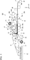
- the manufacturing apparatus 100 is equipped with a fiber bundle supply unit 10, a first carrier sheet supply unit 11, a first conveying unit 20, a first coating unit 12, a cutting machine 13, a second carrier sheet supply unit 14, a second conveying unit 28, a second coating unit 15, an impregnating unit 16, a marking unit 38, and a storage container 40.
- the first carrier sheet supply unit 11 supplies the long first carrier sheet 3 withdrawn from a first original fabric roll R1 to the first conveying unit 20.
- the first conveying unit 20 includes a conveyor 23 in which an endless belt 22 is hung between a pair of pulleys 21a and 21b. In the conveyor 23, the endless belt 22 is orbited as the pair of pulleys 21 a and 21b are rotated in the same direction and the first carrier sheet 3 is conveyed on the surface of the endless belt 22 toward the right side in the X axis direction.
- the first coating unit 12 is positioned right above the pulley 21a side of the first conveying unit 20 and is equipped with a coater 24 for supplying a paste P composed of the matrix resin composition.
- the paste P is coated on the surface of the first carrier sheet 3 in a predetermined thickness and a first resin sheet S1 is thus formed as the first carrier sheet 3 passes through the coater 24.
- the first resin sheet S1 travels as the first carrier sheet 3 is conveyed.
- the fiber bundle supply unit 10 supplies a long fiber bundle f1 toward the cutting machine 13 via a plurality of guide rolls 18 while withdrawing the long fiber bundle f1 from a plurality of bobbins 17.
- the cutting machine 13 is positioned above the first carrier sheet 3 at a stage subsequent to the first coating unit 12 in the conveying direction.
- the cutting machine 13 continuously cuts the fiber bundle f1 supplied by the fiber bundle supply unit 10 into a predetermined length and is equipped with a guide roll 25, a pinch roll 26, and a cutter roll 27.
- the guide roll 25 guides the fiber bundle f1 supplied downward while rotating the fiber bundle f1.
- the pinch roll 26 rotates in a direction opposite to that of the guide roll 25 while sandwiching the fiber bundle f1 between itself and the guide roll 25.
- the fiber bundle f1 is withdrawn from the plurality of bobbins 17.
- the cutter roll 27 cuts the fiber bundle f1 so as to have a predetermined length while rotating.
- a fiber bundle f2 cut into a predetermined length by the cutting machine 13 falls and is scattered on the first resin sheet S1 and a sheet-shaped fiber bundle group F is thus formed.
- the second carrier sheet supply unit 14 supplies the long second carrier sheet 4 withdrawn from the second original fabric roll R2 to the second conveying unit 28.
- the second conveying unit 28 is positioned above the first carrier sheet 3 to be conveyed by the conveyor 23 and equipped with a plurality of guide rolls 29.
- the second conveying unit 28 conveys the second carrier sheet 4 supplied by the second carrier sheet supply unit 14 in a direction opposite to that of the first carrier sheet 3 (left side in the X axis direction) and then reverses the conveyance direction into the same direction as that of the first carrier sheet 3 by the plurality of guide rolls 29.
- the second coating unit 15 is positioned right above the second carrier sheet 4 being conveyed in a direction opposite to that of the first carrier sheet 3 and equipped with a coater 30 for supplying the paste P composed of the matrix resin composition.
- the paste P is coated on the surface of the second carrier sheet 4 in a predetermined thickness and a second resin sheet S2 is formed as the second carrier sheet 4 passes through the coater 30.
- the second resin sheet S2 travels as the second carrier sheet 4 is conveyed.
- the impregnating unit 16 is positioned at a stage subsequent to the cutting machine 13 in the first conveying unit 20 and equipped with a bonding mechanism 31 and a pressurizing mechanism 32.
- the bonding mechanism 31 is positioned above the pulley 21b of the conveyor 23 and equipped with a plurality of bonding rolls 33.
- the plurality of bonding rolls 33 are disposed side by side in the conveying direction in a state of being in contact with the back surface of the second carrier sheet 4 on which the second resin sheet S2 is formed.
- the plurality of bonding rolls 33 are disposed so that the second carrier sheet 4 gradually approaches the first carrier sheet 3.
- the first carrier sheet 3 and the second carrier sheet 4 are conveyed while being superimposed on each other in a state of sandwiching the first resin sheet S1, the sheet-shaped fiber bundle group F, and the second resin sheet S2 therebetween.
- a laminate precursor S3 one in which the first carrier sheet 3 and the second carrier sheet 4 are bonded to each other in a state of sandwiching the first resin sheet S1, the sheet-shaped fiber bundle group F, and the second resin sheet S2 therebetween.
- the pressurizing mechanism 32 is positioned at a stage subsequent to the bonding mechanism 31 and equipped with a lower conveyor 36A in which an endless belt 35 is hung between a pair of pulleys 34a and 34b and an upper conveyor 36B in which an endless belt 35b is hung between a pair of pulleys 34c and 34d.
- the lower conveyor 36A and the upper conveyor 36B are disposed to face each other in a state in which the endless belts 35a and 35b are butted against each other.
- the endless belt 35a is orbited as the pair of pulleys 34a and 34b of the lower conveyor 36A are rotated in the same direction.
- the endless belt 35b is orbited in a direction opposite to that of the endless belt 35a at the same speed as that of the endless belt 35a as the pair of pulleys 34c and 34d of the upper conveyor 36B are rotated in the same direction.
- the pressurizing mechanism 32 is further provided with a plurality of lower rolls 37a and a plurality of upper rolls 37b.
- the plurality of lower rolls 37a are disposed side by side in the conveying direction in a state of being in contact with the back surface of the butted portion of the endless belt 35a.
- the plurality of upper rolls 37b are disposed side by side in the conveying direction in a state of being in contact with the back surface of the butted portion of the endless belt 35b.
- the plurality of lower rolls 37a and the plurality of upper rolls 37b are alternately disposed side by side along the conveying direction of the bonded sheet S3.
- the laminate precursor S3 is pressurized by the plurality of lower rolls 37a and the plurality of upper rolls 37b while the bonded sheet S3 passes through between the endless belts 35a and 35b.
- the sheet-shaped fiber bundle group F is impregnated with the resin of the first resin sheet S1 and the resin of the second resin sheet S2 and a fiber-reinforced resin material (SMC) is thus formed.
- the marking unit 38 forms a mark portion on the outer surface 4a of the second carrier sheet 4.
- the laminate 1 in which the fiber-reinforced resin material (SMC) is sandwiched between the first carrier sheet 3 and the second carrier sheet 4 and a mark portion is provided on the surface 4a of the second carrier sheet 4 is obtained as the mark portion is provide by the marking unit 38.
- the marking unit 38 may be any marking unit as long as a mark portion can be provided at a predetermined position on the surface 4a of the second carrier sheet 4. Examples thereof may include a means equipped with a touch roll for sticking a tape with pressure sensitive adhesive to the surface of the carrier sheet and a means equipped with a coating unit for coating a UV curable resin ink on the surface of the carrier sheet and a UV irradiating unit for irradiating the ink coated with UV and curing the ink irradiated.
- a blasting means for projecting fine sand onto the surface of the carrier sheet and thus forming a mark portion composed of concave and convex on the surface of the carrier sheet and a hairline means for bringing a roll having a surface provided with a concavoconvex shape into contact with the surface of the carrier sheet and thus forming a mark portion composed of concave and convex on the surface of the carrier sheet.
- a blasting means for projecting fine sand onto the surface of the carrier sheet and thus forming a mark portion composed of concave and convex on the surface of the carrier sheet
- a hairline means for bringing a roll having a surface provided with a concavoconvex shape into contact with the surface of the carrier sheet and thus forming a mark portion composed of concave and convex on the surface of the carrier sheet.
- the storage container 40 is a container for storing the laminate 1.
- the storage container 40 is not particularly limited and may be appropriately selected depending on the width, the length, and the like of the laminate 1 to be obtained.
- Fig. 4 illustrates a manufacturing apparatus 100' to be used in another example of the method for manufacturing a fiber-reinforced resin material laminate of the present invention.
- the manufacturing apparatus 100' is the same as the manufacturing apparatus 100 except that the marking unit 38 is moved to the front of the impregnating unit 16.
- the following scattering step, lamination step, impregnation step, and marking step are sequentially carried out.
- Scattering step a step of forming a sheet-shaped fiber bundle group F by continuously cutting the long fiber bundle f1 and scattering a plurality of cut fiber bundles f2 on the first resin sheet S1 formed on the first carrier sheet 3 in a sheet shape.
- Lamination step a step of forming the precursor laminate S3 by laminating the second resin sheet S2 and the second carrier sheet 4 on the sheet-shaped fiber bundle group F in this order.
- Impregnation step a step of forming a fiber-reinforced resin material by pressurizing the laminate precursor S3 from both sides and thus impregnating the sheet-shaped fiber bundle group F with the matrix resin composition.
- Marking step a step of obtaining the laminate 1 by providing a mark portion on the outer surface 4a of the second carrier sheet 4 by marking.
- the first carrier sheet supply unit 11 withdraws the long first carrier sheet 3 from the first original fabric roll R1 and supplies it to the first conveying unit 20, and the paste P is coated on the long first carrier sheet 3 in a predetermined thickness by the first coating unit 12 to form a first resin sheet S1.
- the first resin sheet S1 on the first carrier sheet 3 is caused to travel by conveying the first carrier sheet 3 by the first conveying unit 20.
- the fiber bundle f1 supplied by the fiber bundle supply unit 10 is continuously cut in the cutting machine 13 so as to have a predetermined length and the fiber bundle f2 cut is dropped onto the first resin sheet S1 and scattered.
- the sheet-shaped fiber bundle group F in which the respective fiber bundles f2 are scattered on the traveling first resin sheet S1 in random fiber orientation is continuously formed.
- the second carrier sheet supply unit 14 withdraws the long second carrier sheet 4 from the second original fabric roll R2 and supplies it to the second conveying unit 28.
- the paste P is coated on the surface of the second carrier sheet 4 in a predetermined thickness by the second coating unit 15 to form the second resin sheet S2.
- the second resin sheet S2 is caused to travel by conveying the second carrier sheet 4, and the second resin sheet S2 is bonded and laminated on the sheet-shaped fiber bundle group F together with the second carrier sheet 4 by the bonding mechanism 31.
- the precursor laminate S3 in which the material precursor in which the sheet-shaped fiber bundle group F is sandwiched between the first resin sheet S1 and the second resin sheet S2 is sandwiched between the first carrier sheet 3 and the second carrier sheet 4 is continuously formed.
- a fiber-reinforced resin material is formed between the first carrier sheet 3 and the second carrier sheet 4 by pressurizing the precursor laminate S3 from both sides and thus impregnating the sheet-shaped fiber bundle group F with the matrix resin composition of first resin sheet S1 and second resin sheet S2 by the pressurizing mechanism 32.
- a mark portion is provided at a predetermined position on the outer surface 4a of the second carrier sheet 4 to obtain the laminate 1, and the laminate 1 is sequentially stored in the storage container 40 by, for example, being appropriately cut and transferred.
- the mark portion is limitedly provided at a portion to be the terminal end portion of the laminate 1 to be stored in the storage container 40 on the surface 4a of the second carrier sheet 4 or the mark portion is continuously provided from the starting end (one end) to the terminal end (other end).
- the method of providing the mark portion is not particularly limited, and examples thereof may include a method in which a tape with pressure sensitive adhesive is stuck on the surface of the sheet, a method in which a UV curable resin ink is coated on the surface of the sheet and then cured by being irradiated with UV, a method in which concave and convex are formed on the surface of the sheet by blasting, and a method in which concave and convex are formed on the surface of the sheet by hairline processing.
- the mark portion may be provided using an oil based ink in a case in which the matrix resin composition does not contain a volatile component such as styrene.
- the mark portion may be formed by laser in a case in which the fiber-reinforced resin material does not contain a component which causes inconveniences such as degeneration by laser.
- the carrier sheet meanders by pressurization and the like at the time of impregnation and the position of the mark portion provided on the carrier sheet and the position of the fiber-reinforced resin material which is expected to originally correspond to the position of the mark portion do not match to each other in some cases.
- the mark portions do not match to each other in this manner, inconveniences are caused and the yield decreases as the fiber-reinforced resin material is displaced from the desired position, for example, in the case of performing positioning of the fiber-reinforced resin material laminate by utilizing the mark portion in the cutting and the like.
- the marking step may be carried out before the impregnation step in a case in which the mismatch of mark portions due to the meandering of the carrier sheet is not a significant problem, for example, a lot number is provided as the mark portion.
- a fiber-reinforced resin material laminate may be manufactured by carrying out the respective steps other than the marking step using a carrier sheet provided with a mark portion by previously carrying out the marking step.
- the position may be corrected so that the position of the mark portion matches to the position at which the sheet-shaped bundle group F is formed by scattering a plurality of fiber bundles f2 cut on the first resin sheet S1 formed on the first carrier sheet 3 in a sheet shape and the carrier sheet may be supplied in a case in which the marking step is carried out before the impregnation step or the mark portion is provided on the carrier sheet.
- the following scattering step, marking step, lamination step, and the impregnation step are sequentially carried out.
- Scattering step a step of forming a sheet-shaped fiber bundle group F by continuously cutting the long fiber bundle f1 and scattering a plurality of fiber bundles f2 cut on the first resin sheet S1 formed on the first carrier sheet 3 in a sheet shape.
- Marking step a step of providing a mark portion on the outer surface 4a of the second carrier sheet 4 by marking.
- Lamination step a step of forming the precursor laminate S3 by laminating the second resin sheet S2 and the second carrier sheet 4 on the sheet-shaped fiber bundle group F in this order.
- Impregnation step a step of forming a fiber-reinforced resin material by pressurizing the laminate precursor S3 from both sides and thus impregnating the sheet-shaped fiber bundle group F with the matrix resin composition.
- the scattering step, the marking step, the lamination step, and the impregnation step are the same as the steps described in the method for manufacturing a fiber-reinforced resin material laminate by using the manufacturing apparatus 100.
- a mark portion is provided on the surface of the carrier sheet in the marking step. For this reason, it is easy to handle the fiber-reinforced resin material laminate obtained before molding, for example, positioning is performed by utilizing the mark portion when performing cutting and the like and the fiber-reinforced resin material laminate is managed.
- the method for manufacturing a fiber-reinforced resin material laminate of the present invention is not limited to the methods which have been described above and use the manufacturing apparatuses 100 and 100'.
- the method may be a method in which a mark portion is provided on both of a pair of carrier sheets or a method in which a mark portion is provided only on the surface of the lower carrier sheet.
- the method may also be a method in which the fiber-reinforced resin material laminate manufactured is wound onto a bobbin.
- the method may be a method in which a mark portion is provided on the surface of a carrier sheet by marking after the carrier sheet has been housed in a storage container or wound onto a bobbin.
- the method may be a method in which a mark portion is provided before the carrier sheet wound onto an original fabric roll.
- the mark portion may be provided on the inner surface of the carrier sheet when the carrier sheet is transparent and the inside thereof can be visually recognized in a case in which a fiber-reinforced resin material laminate is manufactured by carrying out steps other than the marking step using a carrier sheet provided with a mark portion previously through the marking step.
- the fiber bundle is a carbon fiber bundle
- the matrix resin composition is an epoxy acrylate resin
- the carrier sheet is a polyethylene film or a polyester film
- the mark portion is a tape with pressure sensitive adhesive
- the tape with pressure sensitive adhesive is one in which a silicone-based pressure sensitive adhesive is coated on a tape base material made of polyester.
- the adhesive property of the mark portion was evaluated by visually confirming the presence or absence of peeling off of the mark portion after the fiber-reinforced resin material laminate was stored at room temperature (25°C) for 20 days.
- a carbon fiber bundle (trade name "TR50S15L", manufactured by Mitsubishi Rayon Co., Ltd.) was used as a long fiber bundle.
- an epoxy acrylate resin product name: NEOPOL 8051, manufactured by U-PICA Company, Ltd.
- thermosetting resin 0.5 part by mass of a 75% solution of 1,1-di(t-butylperoxy)cyclohexane (product name: PERHEXA C-75, manufactured by NOF CORPORATION) and 0.5 part by mass of a 74% solution of t-butylperoxyisopropyl carbonate (product name: Kayacarbon BIC-75, manufactured by Kayaku Akzo Corporation) were added as a curing agent, 0.35 part by mass of a phosphoric acid ester-based derivative composition (product name: MOLD WIZ INT-EQ-6, manufactured by Axel Plastics Research Laboratories, Inc.) was added as an internal release agent, 15.5 parts by mass of a modified diphen
- a fiber-reinforced resin material laminate was manufactured by using the manufacturing apparatus 100 illustrated in Fig. 3 .
- As the marking unit 38 a device equipped with a touch roll for sticking a tape with pressure sensitive adhesive to the surface 4a of the second carrier sheet 4 was used.
- the paste (paste P) prepared above was coated on the first carrier sheet 3 (material: polyethylene film, thickness: 0.05 mm, manufactured by WAKO KASEI CO., LTD.) being conveyed to form a first resin sheet S1 having a thickness of 0.45 mm.
- a carbon fiber bundle (fiber bundle f1) having a thickness of 0.05 mm and a width of 7.5 mm was cut by using a cutting machine and dropped as a chopped fiber bundle (fiber bundle f2) having an average fiber length of 50.8 mm to form a sheet-shaped fiber bundle group F having a thickness of 1.3 mm.
- the paste P was coated on the second carrier sheet 4 (material: polyethylene film, thickness: 0.05 mm, manufactured by WAKO KASEI CO., LTD.) being conveyed in the direction opposite to that of the first carrier sheet 3 above the first carrier sheet 3 to form a second resin sheet S2 having a thickness of 0.45 mm and the second resin sheet S2 was bonded and laminated on the sheet-shaped fiber bundle group F by reversing the conveying direction. Furthermore, impregnation of the precursor laminate S3 sandwiched between the first carrier sheet 3 and the second carrier sheet 4 was performed by the material precursors of the first resin sheet S1, the sheet-shaped fiber bundle group F, and the second resin sheet S2, thereby obtaining a sheet-shaped laminate having a thickness of 2 mm.
- material material: polyethylene film, thickness: 0.05 mm, manufactured by WAKO KASEI CO., LTD.
- a tape with pressure sensitive adhesive which obtained by coating a silicone-based pressure sensitive adhesive on a tape base material made of polyester and had a width of 10 mm and a thickness of 25 mm, was stuck to the center portion in the width direction on the surface 4a of the second carrier sheet 4 along the length direction to provide a mark portion, thereby obtaining a fiber-reinforced resin material laminate.
- the mark portion did not peel off and exhibited sufficient adhesive property.
- a fiber-reinforced resin material laminate of the present invention According to the method for manufacturing a fiber-reinforced resin material laminate of the present invention, a fiber-reinforced resin material laminate which makes it possible to easily carry out steps before molding such as cutting of a fiber-reinforced resin material is obtained.
Landscapes
- Engineering & Computer Science (AREA)
- Mechanical Engineering (AREA)
- Laminated Bodies (AREA)
- Reinforced Plastic Materials (AREA)
- Moulding By Coating Moulds (AREA)
Abstract
Description
- The present invention relates to a fiber-reinforced resin material laminate and a manufacturing method for the same.
- This application is based upon and claims the benefit of priority of the prior Japanese Patent Application No.
2016-037057 - A sheet molding compound (SMC) exhibiting a property of easily flowing at the time of molding using a mold is widely used as a part having partially different wall thicknesses and an intermediate material of a fiber-reinforced resin material molded body having ribs, bosses, and the like. SMC is a fiber-reinforced resin material obtained, for example, by impregnating a sheet-shaped fiber bundle group formed of a plurality of chopped fiber bundles obtained by cutting a long reinforcing fiber such as a glass fiber or a carbon fiber into a predetermined length with a thermosetting resin such as an unsaturated polyester resin. For example, a fiber-reinforced resin material molded body is obtained by appropriately cutting the fiber-reinforced resin material and then molding the cut fiber-reinforced resin material into a desired shape by using a mold.
- As a method for manufacturing the fiber-reinforced resin material, for example, the following method is known. A long fiber-reinforced resin material is obtained by pressurizing a long material precursor in which a sheet-shaped fiber bundle group is sandwiched between a pair of resin sheets formed of a matrix resin composition from both sides and thus impregnating the sheet-shaped fiber bundle group with the matrix resin composition (for example, Patent Literature 1).
- Patent Literature 1:
JP 01-249409 A - However, it is difficult to handle the long fiber-reinforced resin material obtained by a conventional method as disclosed in
Patent Literature 1 in various steps before molding, for example, it is difficult to put the long fiber-reinforced resin material at the right position at the time of cutting before molding. - An object of the present invention is to provide a fiber-reinforced resin material laminate which makes it possible to easily carry out steps before molding such as cutting of a fiber-reinforced resin material and a manufacturing method for the same.
- The present invention provides a fiber-reinforced resin material laminate and a manufacturing method for the same which have the following configurations.
- [1] A fiber-reinforced resin material laminate including a fiber-reinforced resin material obtained by impregnating a fiber bundle group formed of a plurality of fiber bundles with a matrix resin composition and a pair of carrier sheets sandwiching the fiber-reinforced resin material, in which the carrier sheet is provided with a mark portion.
- [2] The fiber-reinforced resin material laminate according to [1], in which the mark portion includes a tape with pressure sensitive adhesive, a cured film formed of a UV curable resin ink, or concave and convex.
- [3] The fiber-reinforced resin material laminate according to [2], in which the pressure sensitive adhesive of the tape with pressure sensitive adhesive is a silicone-based pressure sensitive adhesive.
- [4] The fiber-reinforced resin material laminate according to [2], in which the concave and convex are formed by at least one kind of means selected from the group consisting of a blasting means for projecting fine sand onto a surface of the carrier sheet and a hairline means for bringing a roll having a surface provided with a concavoconvex shape into contact with a surface of the carrier sheet.
- [5] The fiber-reinforced resin material laminate according to any one of [1] to [4], in which the long fiber-reinforced resin material is sandwiched between the pair of long carrier sheets and the mark portion is provided at an end portion in a length direction of the carrier sheet.
- [6] The fiber-reinforced resin material laminate according to any one of [1] to [4], in which the long fiber-reinforced resin material is sandwiched between the pair of long carrier sheets and the mark portion is provided from one end to the other end in a length direction of the carrier sheet.
- [7] A method for manufacturing the fiber-reinforced resin material laminate according to any one of [1] to [6], the method including an impregnation step of forming a fiber-reinforced resin material by pressurizing a laminate precursor disposed between the pair of carrier sheets from both sides using a material precursor having the fiber bundle group sandwiched between a pair of resin sheets formed of the matrix resin composition and thus impregnating the fiber bundle group with the matrix resin composition and a marking step of providing the mark portion on a surface of at least one of the pair of carrier sheets by marking.
- [8] The method for manufacturing the fiber-reinforced resin material laminate according to [7], in which the marking step is carried out after the impregnation step.
- [9] The method for manufacturing the fiber-reinforced resin material laminate according to [7], in which the marking step is carried out before the impregnation step.
- By using the fiber-reinforced resin material laminate of the present invention, it is possible to easily carry out steps before molding such as cutting of a fiber-reinforced resin material.
- According to the method for manufacturing a fiber-reinforced resin material laminate of the present invention, a fiber-reinforced resin material laminate which makes it possible to easily carry out steps before molding such as cutting of a fiber-reinforced resin material is obtained.
-
-
Fig. 1 is a plan view which illustrates an example of a fiber-reinforced resin material laminate of the present invention; -
Fig. 2 is a sectional view taken along the line A-A of the fiber-reinforced resin material laminate illustrated inFig 1 ; -
Fig. 3 is a schematic configuration view which illustrates an example of a manufacturing apparatus to be used in a method for manufacturing a fiber-reinforced resin material laminate of the present invention; and -
Fig. 4 is a schematic configuration view which illustrates another example of a manufacturing apparatus to be used in a method for manufacturing a fiber-reinforced resin material laminate of the present invention. - Hereinafter, an example of the fiber-reinforced resin material laminate of the present invention will be described.
- A fiber-reinforced resin material laminate 1 (hereinafter also simply referred to as the "
laminate 1") of the present embodiment includes a long fiber-reinforcedresin material 2 and a pair of longfirst carrier sheet 3 and a longsecond carrier sheet 4 which sandwich the fiber-reinforcedresin material 2 as illustrated inFigs. 1 and 2 . In thelaminate 1 of this example, thefirst carrier sheet 3 is disposed on the lower side of the fiber-reinforcedresin material 2 and thesecond carrier sheet 4 is disposed on the upper side of the fiber-reinforcedresin material 2. The widths of thefirst carrier sheet 3 and thesecond carrier sheet 4 are wider than the width of the fiber-reinforcedresin material 2. The side edge portions of thefirst carrier sheet 3 and thesecond carrier sheet 4 are in close contact with each other on both sides in the width direction of the fiber-reinforcedresin material 2. Amark portion 5 is provided on anouter surface 4a of thesecond carrier sheet 4. - The fiber-reinforced
resin material 2 is formed by impregnating a sheet-shaped fiber bundle group in which a plurality of fiber bundles are scattered in a sheet shape with a matrix resin composition. - The reinforcing fiber which forms the fiber bundle is not particularly limited, and for example, an inorganic fiber, an organic fiber, a metal fiber, or a reinforcing fiber having a hybrid configuration in which these are combined can be used.
- Examples of the inorganic fiber may include a carbon fiber, a graphite fiber, a silicon carbide fiber, an alumina fiber, a tungsten carbide fiber, a boron fiber, and a glass fiber. Examples of the organic fiber may include an aramid fiber, a high density polyethylene fiber, other general nylon fibers, and a polyester fiber. Examples of the metal fiber may include fibers of stainless steel and iron, and a carbon fiber coated with a metal may also be used. Among these, a carbon fiber is preferable when mechanical properties such as strength of the fiber-reinforced resin material molded body are taken into consideration.
- The reinforcing fiber may be used singly or two or more kinds thereof may be used concurrently.
- The fiber length of the reinforcing fiber is preferably from 5 to 100 mm, more preferably from 10 to 75 mm, and still more preferably from 20 to 60 mm. It is likely to obtain a fiber-reinforced resin material molded body which exhibits excellent physical properties such as tensile strength and modulus of elasticity when the fiber length of the reinforcing fiber is the lower limit value or longer. The fiber-reinforced resin material is more likely to flow at the time of molding and thus molding is facilitated when the fiber length of the reinforcing fiber is the upper limit value or shorter.
- The average thickness of the fiber bundles is preferably from 0.01 to 0.5 mm, more preferably from 0.02 to 0.09 mm, and still more preferably from 0.025 to 0.07 mm. It is easy to impregnate the fiber bundle group with the matrix resin composition when the average thickness of the fiber bundles is the lower limit value or thicker. It is likely to obtain a fiber-reinforced resin material molded body which exhibits excellent physical properties such as tensile strength and modulus of elasticity when the average thickness of the fiber bundles is the upper limit value or thinner.
- Incidentally, the average thickness of the fiber bundles is measured by the following method. The fiber-reinforced resin material is heated in an electric furnace or the like to decompose the matrix resin composition and 10 fiber bundles are randomly selected from the residual fiber bundles. For each of the 10 fiber bundles, the thickness at three points of both end portions in the fiber axial direction and the center portion is measured by using a caliper, all of these measured values are averaged, and the value thus determined is taken as the average thickness.
- The average width of the fiber bundles is preferably from 1 to 50 mm, more preferably from 1.5 to 15 mm, and still more preferably from 2 to 8 mm. The fiber-reinforced resin material is more likely to flow at the time of molding and thus molding is facilitated when the average width of the fiber bundles is the lower limit value or wider. It is easy to obtain a fiber-reinforced resin material molded body which exhibits excellent physical properties such as tensile strength and modulus of elasticity when the average width of the fiber bundles is the upper limit value or narrower.
- Incidentally, the average width of the fiber bundles is measured by the following method. For each of the 10 fiber bundles obtained in the same manner as in the measurement of the average thickness, the width at three points of both end portions and center portion in the fiber axis direction is measured by using a caliper, all of these measured values are averaged, and the value thus determined is taken as the average width.
- As the matrix resin composition, a composition containing a thermosetting resin is preferable.
- The thermosetting resin is not particularly limited, and examples thereof may include an epoxy resin, a phenol resin, an unsaturated polyester resin, a urethane resin, a urea resin, a melamine resin, and an imide resin. Among these, an acrylate resin having an epoxy group (epoxy acrylate resin) is preferable. The thermosetting resin may be used singly or two or more kinds thereof may be used concurrently.
- Additives such as a curing agent, an internal release agent, a thickening agent, and a stabilizer may be blended into the matrix resin composition if necessary.
- The pair of the
first carrier sheet 3 and thesecond carrier sheet 4 are sheets which sandwich the fiber-reinforcedresin material 2. At the time of molding, thefirst carrier sheet 3 and thesecond carrier sheet 4 are peeled off from the fiber-reinforcedresin material 2. - The material which forms the carrier sheet is not particularly limited as long as it can sandwich the fiber-reinforced resin material without degenerating the fiber-reinforced resin material, and examples thereof may include a film of a polyolefin such as polyethylene or polypropylene, a film of polyamide, polyvinyl alcohol, EVA, or the like, or a multilayer laminate film including these.
- The pair of carrier sheets may be the same as or different from each other.
- The thickness of the carrier sheet is preferably from 0.01 to 0.25 mm and more preferably from 0.04 to 0.1 mm. It is possible to suppress breakage of the carrier sheet during the manufacture of the fiber-reinforced resin material, particularly during the impregnation step when the thickness of the carrier sheet is the lower limit value or thicker. The post-processing such as cutting of the fiber-reinforced resin material laminate is facilitated when the thickness of the carrier sheet is the upper limit value or thinner.
- Incidentally, the thickness can be measured by using a micrometer.
- A
mark portion 5 is provided on theouter surface 4a of thesecond carrier sheet 4 disposed on the upper side of the fiber-reinforcedresin material 2. Themark portion 5 in this example has a band shape and is provided at the center portion in the width direction of thesurface 4a of thesecond carrier sheet 4 in the length direction of thesecond carrier sheet 4. - It is possible to easily carry out steps before molding such as cutting of the fiber-reinforced resin material laminate as the mark portion is provided. Specifically, for example, by utilizing the mark portion for positioning of the laminate at the time of cutting, it is possible to perform the positioning of the laminate more accurately and efficiently, to perform the cutting without waste, to take out the material by cutting the fiber-reinforced
resin material 2 at the stable weight portion, and thus to improve the yield at the time of molding. In addition, it is easy to manage and handle the fiber-reinforced resin material laminate when a lot number is provided as the mark portion. - The mode in which the mark portion is provided on the surface of the carrier sheet is not particularly limited, and a mark portion can be provided at the end portion in the length direction of the carrier sheet, for example, in a case in which a long fiber-reinforced resin material is sandwiched between a pair of long carrier sheets as in this example. The mode in which the mark portion is limitedly provided at the end portion of the carrier sheet in this manner is advantageous in terms of cost. Furthermore, inconveniences such as excessive winding and tightening due to a difference in elongation percentage are hardly caused even when there is a difference between the elongation percentage of the mark portion and the elongation percentage of the carrier sheet or fiber-reinforced resin material.
- In addition, it is preferable to provide a mark portion at the terminal end portion of the laminate when storing a long laminate in a storage container or winding it onto a bobbin. In such a storage body, the terminal end portion of the laminate is usually positioned on the outermost side and thus the mark portion can be easily recognized and utilized at the time of use even when the mark portion is limitedly provided.
- In addition, a belt-shaped mark portion may be provided from one end to the other end in the length direction of the carrier sheet in a case in which a long fiber-reinforced resin material is sandwiched between a pair of long carrier sheets. It is possible to utilize the mark portion even in a case in which the use of the long laminate is stopped in the middle and then restarted by providing the mark portion in this manner.
- The mark portion is not particularly limited, and for example, it may be a tape with pressure sensitive adhesive, a cured film formed of a UV curable resin ink, or concave and convex. When these mark portions are provided, it is possible to prevent the mark portion from being eliminated by the volatile component even in a case in which the fiber-reinforced resin material contains a volatile component such as styrene. In addition, it is possible to suppress the occurrence of inconveniences such as degeneration of the fiber-reinforced resin material when providing the mark portion.
- The tape with pressure sensitive adhesive is not particularly limited, and examples thereof may include one in which a silicone-based pressure sensitive adhesive is coated on a tape base material made of polyester. When a silicone-based pressure sensitive adhesive is used as the pressure sensitive adhesive, it is possible to prevent the tape from peeling off by the volatile component even in a case in which the fiber-reinforced resin material contains a volatile component such as styrene.
- As the silicone-based pressure sensitive adhesive, it is preferable to use one containing an addition curing type polyorganosilicone. Examples of the silicone-based pressure sensitive adhesive may include those composed of a polymer having a siloxane bond in the main skeleton.
- In addition, as the UV curable resin ink, for example, an ink containing organic and inorganic pigments is preferable. Examples of the method of curing the UV curable resin ink and forming a cured film may include a method in which a UV curable resin ink is coated on the surface of the carrier sheet and then irradiated with UV to form a cured film.
- In addition, the concave and convex can be formed, for example, by using a blasting means for projecting fine sand onto the surface of the carrier sheet and a hairline means for bringing this roll having a surface provided with a concavoconvex shape into contact with the surface of the carrier sheet.
- The concave and convex mean a portion (convex portion) protruding outward from the surface of the carrier sheet by from 5 to 100 µm or a portion (concave portion) recessed inward from the surface of the carrier sheet by from 5 to 50 µm.
- Incidentally, bleeding, distortion, and the like are likely to occur at the mark portion formed of an oil based ink by a volatile component such as styrene. However, a mark portion formed of an oil based ink may be provided in a case in which the fiber-reinforced resin material does not contain a volatile component such as styrene.
- In a case in which the mark portion has a belt shape, the width, thickness, and length of the mark portion are not particularly limited and can be appropriately determined depending on the application.
- The shape of the mark portion is not limited to the band shape, and, for example, it may be a broken line shape, a circular shape, or a rectangular shape or it may be a character such as a numeral.
- The number of the mark portions is not particularly limited and can be appropriately determined.
- As described above, in the fiber-reinforced resin material laminate of the present invention, a mark portion is provided on the surface of the carrier sheet. For this reason, it is possible to easily carry out various steps for handling the fiber-reinforced resin material before molding, for example, positioning is performed at the time of cutting and the like by utilizing the mark portion or the fiber-reinforced resin material laminate is managed.
- Incidentally, the fiber-reinforced resin material laminate of the present invention is not limited to the
laminate 1 described above. For example, the fiber-reinforced resin material laminate of the present invention may have a mark portion on both of a pair of carrier sheets. In addition, the fiber-reinforced resin material laminate is not required to be long. - In addition, a mark portion may be provided on the inner surface of the carrier sheet in a case in which the carrier sheet is transparent and the inside thereof can be visually recognized.
- The method for manufacturing a fiber-reinforced resin material laminate of the present invention has the following impregnation step and marking step.
- Impregnation step: a step of forming a fiber-reinforced resin material by pressurizing a laminate precursor disposed between a pair of carrier sheets from both sides using a material precursor having a fiber bundle group sandwiched between a pair of resin sheets formed of a matrix resin composition and thus impregnating the fiber bundle group with the matrix resin composition.
- Marking step: a step of providing a mark portion on the surface of at least one of the pair of carrier sheets by marking.
- Hereinafter, as an example of the manufacturing method for a fiber-reinforced resin material laminate of the present invention, a case of using a
manufacturing apparatus 100 illustrated inFig. 3 will be described as an example. In the following description, an XYZ orthogonal coordinate system is set, and the positional relation among the respective members will be described while referring to this XYZ orthogonal coordinate system if necessary. - The
manufacturing apparatus 100 is equipped with a fiberbundle supply unit 10, a first carriersheet supply unit 11, a first conveyingunit 20, afirst coating unit 12, a cuttingmachine 13, a second carriersheet supply unit 14, a second conveyingunit 28, asecond coating unit 15, an impregnatingunit 16, a markingunit 38, and astorage container 40. - The first carrier
sheet supply unit 11 supplies the longfirst carrier sheet 3 withdrawn from a first original fabric roll R1 to the first conveyingunit 20. The first conveyingunit 20 includes aconveyor 23 in which anendless belt 22 is hung between a pair ofpulleys conveyor 23, theendless belt 22 is orbited as the pair ofpulleys first carrier sheet 3 is conveyed on the surface of theendless belt 22 toward the right side in the X axis direction. - The
first coating unit 12 is positioned right above thepulley 21a side of the first conveyingunit 20 and is equipped with acoater 24 for supplying a paste P composed of the matrix resin composition. The paste P is coated on the surface of thefirst carrier sheet 3 in a predetermined thickness and a first resin sheet S1 is thus formed as thefirst carrier sheet 3 passes through thecoater 24. The first resin sheet S1 travels as thefirst carrier sheet 3 is conveyed. - The fiber
bundle supply unit 10 supplies a long fiber bundle f1 toward the cuttingmachine 13 via a plurality of guide rolls 18 while withdrawing the long fiber bundle f1 from a plurality ofbobbins 17. The cuttingmachine 13 is positioned above thefirst carrier sheet 3 at a stage subsequent to thefirst coating unit 12 in the conveying direction. The cuttingmachine 13 continuously cuts the fiber bundle f1 supplied by the fiberbundle supply unit 10 into a predetermined length and is equipped with aguide roll 25, apinch roll 26, and acutter roll 27. Theguide roll 25 guides the fiber bundle f1 supplied downward while rotating the fiber bundle f1. Thepinch roll 26 rotates in a direction opposite to that of theguide roll 25 while sandwiching the fiber bundle f1 between itself and theguide roll 25. By this, the fiber bundle f1 is withdrawn from the plurality ofbobbins 17. Thecutter roll 27 cuts the fiber bundle f1 so as to have a predetermined length while rotating. A fiber bundle f2 cut into a predetermined length by the cuttingmachine 13 falls and is scattered on the first resin sheet S1 and a sheet-shaped fiber bundle group F is thus formed. - The second carrier
sheet supply unit 14 supplies the longsecond carrier sheet 4 withdrawn from the second original fabric roll R2 to the second conveyingunit 28. The second conveyingunit 28 is positioned above thefirst carrier sheet 3 to be conveyed by theconveyor 23 and equipped with a plurality of guide rolls 29. The second conveyingunit 28 conveys thesecond carrier sheet 4 supplied by the second carriersheet supply unit 14 in a direction opposite to that of the first carrier sheet 3 (left side in the X axis direction) and then reverses the conveyance direction into the same direction as that of thefirst carrier sheet 3 by the plurality of guide rolls 29. - The
second coating unit 15 is positioned right above thesecond carrier sheet 4 being conveyed in a direction opposite to that of thefirst carrier sheet 3 and equipped with acoater 30 for supplying the paste P composed of the matrix resin composition. The paste P is coated on the surface of thesecond carrier sheet 4 in a predetermined thickness and a second resin sheet S2 is formed as thesecond carrier sheet 4 passes through thecoater 30. The second resin sheet S2 travels as thesecond carrier sheet 4 is conveyed. - The impregnating
unit 16 is positioned at a stage subsequent to the cuttingmachine 13 in the first conveyingunit 20 and equipped with abonding mechanism 31 and apressurizing mechanism 32. Thebonding mechanism 31 is positioned above thepulley 21b of theconveyor 23 and equipped with a plurality of bonding rolls 33. The plurality of bonding rolls 33 are disposed side by side in the conveying direction in a state of being in contact with the back surface of thesecond carrier sheet 4 on which the second resin sheet S2 is formed. In addition, the plurality of bonding rolls 33 are disposed so that thesecond carrier sheet 4 gradually approaches thefirst carrier sheet 3. - In the
bonding mechanism 31, thefirst carrier sheet 3 and thesecond carrier sheet 4 are conveyed while being superimposed on each other in a state of sandwiching the first resin sheet S1, the sheet-shaped fiber bundle group F, and the second resin sheet S2 therebetween. Here, one in which thefirst carrier sheet 3 and thesecond carrier sheet 4 are bonded to each other in a state of sandwiching the first resin sheet S1, the sheet-shaped fiber bundle group F, and the second resin sheet S2 therebetween is referred to as a laminate precursor S3. - The
pressurizing mechanism 32 is positioned at a stage subsequent to thebonding mechanism 31 and equipped with alower conveyor 36A in which an endless belt 35 is hung between a pair ofpulleys upper conveyor 36B in which anendless belt 35b is hung between a pair ofpulleys lower conveyor 36A and theupper conveyor 36B are disposed to face each other in a state in which theendless belts - In the
pressurizing mechanism 32, theendless belt 35a is orbited as the pair ofpulleys lower conveyor 36A are rotated in the same direction. In addition, in thepressurizing mechanism 32, theendless belt 35b is orbited in a direction opposite to that of theendless belt 35a at the same speed as that of theendless belt 35a as the pair ofpulleys upper conveyor 36B are rotated in the same direction. By this, the laminate precursor S3 sandwiched between theendless belts - The
pressurizing mechanism 32 is further provided with a plurality oflower rolls 37a and a plurality ofupper rolls 37b. The plurality oflower rolls 37a are disposed side by side in the conveying direction in a state of being in contact with the back surface of the butted portion of theendless belt 35a. In the same manner, the plurality ofupper rolls 37b are disposed side by side in the conveying direction in a state of being in contact with the back surface of the butted portion of theendless belt 35b. In addition, the plurality oflower rolls 37a and the plurality ofupper rolls 37b are alternately disposed side by side along the conveying direction of the bonded sheet S3. - In the
pressurizing mechanism 32, the laminate precursor S3 is pressurized by the plurality oflower rolls 37a and the plurality ofupper rolls 37b while the bonded sheet S3 passes through between theendless belts - The marking
unit 38 forms a mark portion on theouter surface 4a of thesecond carrier sheet 4. Thelaminate 1 in which the fiber-reinforced resin material (SMC) is sandwiched between thefirst carrier sheet 3 and thesecond carrier sheet 4 and a mark portion is provided on thesurface 4a of thesecond carrier sheet 4 is obtained as the mark portion is provide by the markingunit 38. - The marking
unit 38 may be any marking unit as long as a mark portion can be provided at a predetermined position on thesurface 4a of thesecond carrier sheet 4. Examples thereof may include a means equipped with a touch roll for sticking a tape with pressure sensitive adhesive to the surface of the carrier sheet and a means equipped with a coating unit for coating a UV curable resin ink on the surface of the carrier sheet and a UV irradiating unit for irradiating the ink coated with UV and curing the ink irradiated. In addition, it is also possible to use a blasting means for projecting fine sand onto the surface of the carrier sheet and thus forming a mark portion composed of concave and convex on the surface of the carrier sheet and a hairline means for bringing a roll having a surface provided with a concavoconvex shape into contact with the surface of the carrier sheet and thus forming a mark portion composed of concave and convex on the surface of the carrier sheet. These means may be used singly or two or more kinds thereof may be used concurrently. - The
storage container 40 is a container for storing thelaminate 1. Thestorage container 40 is not particularly limited and may be appropriately selected depending on the width, the length, and the like of thelaminate 1 to be obtained. -
Fig. 4 illustrates a manufacturing apparatus 100' to be used in another example of the method for manufacturing a fiber-reinforced resin material laminate of the present invention. - The manufacturing apparatus 100' is the same as the
manufacturing apparatus 100 except that the markingunit 38 is moved to the front of the impregnatingunit 16. - In the method for manufacturing a fiber-reinforced resin material laminate using the
manufacturing apparatus 100, for example, the following scattering step, lamination step, impregnation step, and marking step are sequentially carried out. - Scattering step: a step of forming a sheet-shaped fiber bundle group F by continuously cutting the long fiber bundle f1 and scattering a plurality of cut fiber bundles f2 on the first resin sheet S1 formed on the
first carrier sheet 3 in a sheet shape. - Lamination step: a step of forming the precursor laminate S3 by laminating the second resin sheet S2 and the
second carrier sheet 4 on the sheet-shaped fiber bundle group F in this order. - Impregnation step: a step of forming a fiber-reinforced resin material by pressurizing the laminate precursor S3 from both sides and thus impregnating the sheet-shaped fiber bundle group F with the matrix resin composition.
- Marking step: a step of obtaining the
laminate 1 by providing a mark portion on theouter surface 4a of thesecond carrier sheet 4 by marking. - The first carrier
sheet supply unit 11 withdraws the longfirst carrier sheet 3 from the first original fabric roll R1 and supplies it to the first conveyingunit 20, and the paste P is coated on the longfirst carrier sheet 3 in a predetermined thickness by thefirst coating unit 12 to form a first resin sheet S1. The first resin sheet S1 on thefirst carrier sheet 3 is caused to travel by conveying thefirst carrier sheet 3 by the first conveyingunit 20. - The fiber bundle f1 supplied by the fiber
bundle supply unit 10 is continuously cut in the cuttingmachine 13 so as to have a predetermined length and the fiber bundle f2 cut is dropped onto the first resin sheet S1 and scattered. By this, the sheet-shaped fiber bundle group F in which the respective fiber bundles f2 are scattered on the traveling first resin sheet S1 in random fiber orientation is continuously formed. - The second carrier
sheet supply unit 14 withdraws the longsecond carrier sheet 4 from the second original fabric roll R2 and supplies it to the second conveyingunit 28. The paste P is coated on the surface of thesecond carrier sheet 4 in a predetermined thickness by thesecond coating unit 15 to form the second resin sheet S2. - The second resin sheet S2 is caused to travel by conveying the
second carrier sheet 4, and the second resin sheet S2 is bonded and laminated on the sheet-shaped fiber bundle group F together with thesecond carrier sheet 4 by thebonding mechanism 31. By this, the precursor laminate S3 in which the material precursor in which the sheet-shaped fiber bundle group F is sandwiched between the first resin sheet S1 and the second resin sheet S2 is sandwiched between thefirst carrier sheet 3 and thesecond carrier sheet 4 is continuously formed. - A fiber-reinforced resin material is formed between the
first carrier sheet 3 and thesecond carrier sheet 4 by pressurizing the precursor laminate S3 from both sides and thus impregnating the sheet-shaped fiber bundle group F with the matrix resin composition of first resin sheet S1 and second resin sheet S2 by thepressurizing mechanism 32. - In the marking
unit 38, a mark portion is provided at a predetermined position on theouter surface 4a of thesecond carrier sheet 4 to obtain thelaminate 1, and thelaminate 1 is sequentially stored in thestorage container 40 by, for example, being appropriately cut and transferred. For example, the mark portion is limitedly provided at a portion to be the terminal end portion of thelaminate 1 to be stored in thestorage container 40 on thesurface 4a of thesecond carrier sheet 4 or the mark portion is continuously provided from the starting end (one end) to the terminal end (other end). - The method of providing the mark portion is not particularly limited, and examples thereof may include a method in which a tape with pressure sensitive adhesive is stuck on the surface of the sheet, a method in which a UV curable resin ink is coated on the surface of the sheet and then cured by being irradiated with UV, a method in which concave and convex are formed on the surface of the sheet by blasting, and a method in which concave and convex are formed on the surface of the sheet by hairline processing. Incidentally, the mark portion may be provided using an oil based ink in a case in which the matrix resin composition does not contain a volatile component such as styrene. In addition, the mark portion may be formed by laser in a case in which the fiber-reinforced resin material does not contain a component which causes inconveniences such as degeneration by laser.
- When the marking step is carried out before the impregnation step, the carrier sheet meanders by pressurization and the like at the time of impregnation and the position of the mark portion provided on the carrier sheet and the position of the fiber-reinforced resin material which is expected to originally correspond to the position of the mark portion do not match to each other in some cases. When the mark portions do not match to each other in this manner, inconveniences are caused and the yield decreases as the fiber-reinforced resin material is displaced from the desired position, for example, in the case of performing positioning of the fiber-reinforced resin material laminate by utilizing the mark portion in the cutting and the like. For this reason, it is preferable to carry out the marking step after the impregnation step as in this example in the case of performing positioning of the fiber-reinforced resin material laminate by utilizing the mark portion.
- Incidentally, the marking step may be carried out before the impregnation step in a case in which the mismatch of mark portions due to the meandering of the carrier sheet is not a significant problem, for example, a lot number is provided as the mark portion. For example, a fiber-reinforced resin material laminate may be manufactured by carrying out the respective steps other than the marking step using a carrier sheet provided with a mark portion by previously carrying out the marking step.
- In addition, the position may be corrected so that the position of the mark portion matches to the position at which the sheet-shaped bundle group F is formed by scattering a plurality of fiber bundles f2 cut on the first resin sheet S1 formed on the
first carrier sheet 3 in a sheet shape and the carrier sheet may be supplied in a case in which the marking step is carried out before the impregnation step or the mark portion is provided on the carrier sheet. - In the method for manufacturing a fiber-reinforced resin material laminate by using the manufacturing apparatus 100', for example, the following scattering step, marking step, lamination step, and the impregnation step are sequentially carried out.
- Scattering step: a step of forming a sheet-shaped fiber bundle group F by continuously cutting the long fiber bundle f1 and scattering a plurality of fiber bundles f2 cut on the first resin sheet S1 formed on the
first carrier sheet 3 in a sheet shape. - Marking step: a step of providing a mark portion on the
outer surface 4a of thesecond carrier sheet 4 by marking. - Lamination step: a step of forming the precursor laminate S3 by laminating the second resin sheet S2 and the
second carrier sheet 4 on the sheet-shaped fiber bundle group F in this order. - Impregnation step: a step of forming a fiber-reinforced resin material by pressurizing the laminate precursor S3 from both sides and thus impregnating the sheet-shaped fiber bundle group F with the matrix resin composition.
- The scattering step, the marking step, the lamination step, and the impregnation step are the same as the steps described in the method for manufacturing a fiber-reinforced resin material laminate by using the
manufacturing apparatus 100. - In the method for manufacturing a fiber-reinforced resin material laminate of the present invention described above, a mark portion is provided on the surface of the carrier sheet in the marking step. For this reason, it is easy to handle the fiber-reinforced resin material laminate obtained before molding, for example, positioning is performed by utilizing the mark portion when performing cutting and the like and the fiber-reinforced resin material laminate is managed.
- Incidentally, the method for manufacturing a fiber-reinforced resin material laminate of the present invention is not limited to the methods which have been described above and use the
manufacturing apparatuses 100 and 100'. For example, the method may be a method in which a mark portion is provided on both of a pair of carrier sheets or a method in which a mark portion is provided only on the surface of the lower carrier sheet. The method may also be a method in which the fiber-reinforced resin material laminate manufactured is wound onto a bobbin. - In addition, the method may be a method in which a mark portion is provided on the surface of a carrier sheet by marking after the carrier sheet has been housed in a storage container or wound onto a bobbin.
- In addition, the method may be a method in which a mark portion is provided before the carrier sheet wound onto an original fabric roll.
- In addition, the mark portion may be provided on the inner surface of the carrier sheet when the carrier sheet is transparent and the inside thereof can be visually recognized in a case in which a fiber-reinforced resin material laminate is manufactured by carrying out steps other than the marking step using a carrier sheet provided with a mark portion previously through the marking step.
- In the fiber-reinforced resin material laminate of the present invention, it is preferable that the fiber bundle is a carbon fiber bundle, the matrix resin composition is an epoxy acrylate resin, the carrier sheet is a polyethylene film or a polyester film, the mark portion is a tape with pressure sensitive adhesive, and the tape with pressure sensitive adhesive is one in which a silicone-based pressure sensitive adhesive is coated on a tape base material made of polyester.
- Hereinafter, the present invention will be described in detail with reference to Examples, but the present invention is not limited by the following description.
- With regard to the mark portion of the fiber-reinforced resin material laminate obtained, the adhesive property of the mark portion was evaluated by visually confirming the presence or absence of peeling off of the mark portion after the fiber-reinforced resin material laminate was stored at room temperature (25°C) for 20 days.
- A carbon fiber bundle (trade name "TR50S15L", manufactured by Mitsubishi Rayon Co., Ltd.) was used as a long fiber bundle. To 100 parts by mass of an epoxy acrylate resin (product name: NEOPOL 8051, manufactured by U-PICA Company, Ltd.), which was a thermosetting resin, 0.5 part by mass of a 75% solution of 1,1-di(t-butylperoxy)cyclohexane (product name: PERHEXA C-75, manufactured by NOF CORPORATION) and 0.5 part by mass of a 74% solution of t-butylperoxyisopropyl carbonate (product name: Kayacarbon BIC-75, manufactured by Kayaku Akzo Corporation) were added as a curing agent, 0.35 part by mass of a phosphoric acid ester-based derivative composition (product name: MOLD WIZ INT-EQ-6, manufactured by Axel Plastics Research Laboratories, Inc.) was added as an internal release agent, 15.5 parts by mass of a modified diphenylmethane diisocyanate (product name: COSMONATE LL, manufactured by Mitsui Chemicals, Inc.) was added as a thickening agent, and 0.02 part by mass of 1,4-benzoquinone (product name: p-benzoquinone, manufactured by Wako Pure Chemical Industries, Ltd.) was added as a stabilizer, and these were thoroughly mixed and stirred to obtain a matrix resin composition (paste).
- A fiber-reinforced resin material laminate was manufactured by using the
manufacturing apparatus 100 illustrated inFig. 3 . As the markingunit 38, a device equipped with a touch roll for sticking a tape with pressure sensitive adhesive to thesurface 4a of thesecond carrier sheet 4 was used. - The paste (paste P) prepared above was coated on the first carrier sheet 3 (material: polyethylene film, thickness: 0.05 mm, manufactured by WAKO KASEI CO., LTD.) being conveyed to form a first resin sheet S1 having a thickness of 0.45 mm. In addition, a carbon fiber bundle (fiber bundle f1) having a thickness of 0.05 mm and a width of 7.5 mm was cut by using a cutting machine and dropped as a chopped fiber bundle (fiber bundle f2) having an average fiber length of 50.8 mm to form a sheet-shaped fiber bundle group F having a thickness of 1.3 mm. The paste P was coated on the second carrier sheet 4 (material: polyethylene film, thickness: 0.05 mm, manufactured by WAKO KASEI CO., LTD.) being conveyed in the direction opposite to that of the
first carrier sheet 3 above thefirst carrier sheet 3 to form a second resin sheet S2 having a thickness of 0.45 mm and the second resin sheet S2 was bonded and laminated on the sheet-shaped fiber bundle group F by reversing the conveying direction. Furthermore, impregnation of the precursor laminate S3 sandwiched between thefirst carrier sheet 3 and thesecond carrier sheet 4 was performed by the material precursors of the first resin sheet S1, the sheet-shaped fiber bundle group F, and the second resin sheet S2, thereby obtaining a sheet-shaped laminate having a thickness of 2 mm. A tape with pressure sensitive adhesive, which obtained by coating a silicone-based pressure sensitive adhesive on a tape base material made of polyester and had a width of 10 mm and a thickness of 25 mm, was stuck to the center portion in the width direction on thesurface 4a of thesecond carrier sheet 4 along the length direction to provide a mark portion, thereby obtaining a fiber-reinforced resin material laminate. - In the fiber-reinforced resin material laminate thus obtained, the mark portion did not peel off and exhibited sufficient adhesive property.
- By using the fiber-reinforced resin material laminate of the present invention, it is possible to easily carry out steps before molding such as cutting of a fiber-reinforced resin material.
- According to the method for manufacturing a fiber-reinforced resin material laminate of the present invention, a fiber-reinforced resin material laminate which makes it possible to easily carry out steps before molding such as cutting of a fiber-reinforced resin material is obtained.
-
- 1
- Fiber-reinforced resin material laminate
- 2
- Fiber-reinforced resin material
- 3
- First Carrier Sheet
- 4
- Second Carrier Sheet
- 4a
- Surface of second carrier sheet
- 5
- Mark portion
Claims (9)
- A fiber-reinforced resin material laminate comprising:a fiber-reinforced resin material obtained by impregnating a fiber bundle group formed of a plurality of fiber bundles with a matrix resin composition; anda pair of carrier sheets sandwiching the fiber-reinforced resin material, whereinthe carrier sheet is provided with a mark portion.
- The fiber-reinforced resin material laminate according to claim 1, wherein the mark portion includes a tape with pressure sensitive adhesive, a cured film formed of a UV curable resin ink, or concave and convex.
- The fiber-reinforced resin material laminate according to claim 2, wherein the pressure sensitive adhesive of the tape with pressure sensitive adhesive is a silicone-based pressure sensitive adhesive.
- The fiber-reinforced resin material laminate according to claim 2, wherein the concave and convex are formed by at least one kind of means selected from the group consisting of a blasting means for projecting fine sand onto a surface of the carrier sheet and a hairline means for bringing a roll having a surface provided with a concavoconvex shape into contact with a surface of the carrier sheet.
- The fiber-reinforced resin material laminate according to any one of claims 1 to 4, wherein the long fiber-reinforced resin material is sandwiched between the pair of long carrier sheets and the mark portion is provided at an end portion in a length direction of the carrier sheet.
- The fiber-reinforced resin material laminate according to any one of claims 1 to 4, wherein the long fiber-reinforced resin material is sandwiched between the pair of long carrier sheets and the mark portion is provided from one end to the other end in a length direction of the carrier sheet.
- A method for manufacturing the fiber-reinforced resin material laminate according to any one of claims 1 to 6, the method comprising:an impregnation step of forming a fiber-reinforced resin material by pressurizing a laminate precursor disposed between the pair of carrier sheets from both sides using a material precursor having the fiber bundle group sandwiched between a pair of resin sheets formed of the matrix resin composition and thus impregnating the fiber bundle group with the matrix resin composition; anda marking step of providing the mark portion on a surface of at least one of the pair of carrier sheets by marking.
- The method for manufacturing the fiber-reinforced resin material laminate according to claim 7, wherein the marking step is carried out after the impregnation step.
- The method for manufacturing the fiber-reinforced resin material laminate according to claim 7, wherein the marking step is carried out before the impregnation step.
Applications Claiming Priority (2)
| Application Number | Priority Date | Filing Date | Title |
|---|---|---|---|
| JP2016037057 | 2016-02-29 | ||
| PCT/JP2017/007773 WO2017150529A1 (en) | 2016-02-29 | 2017-02-28 | Fiber-reinforced resin material laminate and manufacturing method for same |
Publications (2)
| Publication Number | Publication Date |
|---|---|
| EP3424701A1 true EP3424701A1 (en) | 2019-01-09 |
| EP3424701A4 EP3424701A4 (en) | 2019-08-07 |
Family
ID=59744068
Family Applications (1)
| Application Number | Title | Priority Date | Filing Date |
|---|---|---|---|
| EP17759995.8A Withdrawn EP3424701A4 (en) | 2016-02-29 | 2017-02-28 | LAMINATE OF FIBER REINFORCED RESIN MATERIAL AND METHOD OF MANUFACTURING THE SAME |
Country Status (5)
| Country | Link |
|---|---|
| US (1) | US20180354243A1 (en) |
| EP (1) | EP3424701A4 (en) |
| JP (1) | JP6468351B2 (en) |
| CN (1) | CN108698365A (en) |
| WO (1) | WO2017150529A1 (en) |
Families Citing this family (1)
| Publication number | Priority date | Publication date | Assignee | Title |
|---|---|---|---|---|
| CN113289860A (en) * | 2021-04-25 | 2021-08-24 | 中国五冶集团有限公司 | Pre-paved TPO waterproof coiled material sand-lined device |
Family Cites Families (12)
| Publication number | Priority date | Publication date | Assignee | Title |
|---|---|---|---|---|
| JPH0822550B2 (en) | 1988-03-29 | 1996-03-06 | シュミット ウント ハインツマン ゲーエムベーハー ウント コー カーゲー | Defoaming device in sheet material molding device, wire mesh belt and pressing roller used in the device |
| JPH05269881A (en) * | 1992-01-29 | 1993-10-19 | Toshiba Mach Co Ltd | Method and apparatus for manufacturing prepreg laminated material |
| JP4989822B2 (en) * | 2001-04-27 | 2012-08-01 | 三菱レイヨン株式会社 | Manufacturing method of prepreg |
| JP2003006586A (en) * | 2001-06-18 | 2003-01-10 | Aisin Engineering Kk | Device with identification code, method of manufacturing the same, and identification code reading system |
| JP4496737B2 (en) * | 2003-09-03 | 2010-07-07 | 東レ株式会社 | Separation membrane forming apparatus and method |
| JP2009172995A (en) * | 2007-12-27 | 2009-08-06 | Ube Nitto Kasei Co Ltd | Thermoplastic resin-coated FRP filament and method for producing the same |
| US9180653B2 (en) * | 2011-10-28 | 2015-11-10 | Toray Industries, Inc. | Prepreg production method |
| JP2013125082A (en) * | 2011-12-13 | 2013-06-24 | Seiko Epson Corp | Marking apparatus and marking method |
| KR101829593B1 (en) * | 2012-09-06 | 2018-03-29 | 미쯔비시 케미컬 주식회사 | Prepreg and method for producing same |
| JP2014191867A (en) * | 2013-03-26 | 2014-10-06 | Panasonic Corp | Gas diffusion layer, membrane electrode assembly and method of manufacturing the same |
| US9738783B2 (en) * | 2013-09-26 | 2017-08-22 | Blue Cube Ip Llc | Curable epoxy compositions |
| CN104708836B (en) * | 2013-12-12 | 2017-10-27 | 振石集团华美新材料有限公司 | The preparation method of carbon fiber prepreg |
-
2017
- 2017-02-28 CN CN201780013693.XA patent/CN108698365A/en active Pending
- 2017-02-28 EP EP17759995.8A patent/EP3424701A4/en not_active Withdrawn
- 2017-02-28 JP JP2017515849A patent/JP6468351B2/en active Active
- 2017-02-28 WO PCT/JP2017/007773 patent/WO2017150529A1/en not_active Ceased
-
2018
- 2018-08-17 US US16/104,198 patent/US20180354243A1/en not_active Abandoned
Also Published As
| Publication number | Publication date |
|---|---|
| WO2017150529A1 (en) | 2017-09-08 |
| EP3424701A4 (en) | 2019-08-07 |
| CN108698365A (en) | 2018-10-23 |
| JPWO2017150529A1 (en) | 2018-03-08 |
| US20180354243A1 (en) | 2018-12-13 |
| JP6468351B2 (en) | 2019-02-13 |
Similar Documents
| Publication | Publication Date | Title |
|---|---|---|
| US10889025B2 (en) | Method for manufacturing fiber-reinforced resin molding material, and device for manufacturing fiber-reinforced resin molding material | |
| JP7201063B2 (en) | METHOD FOR MANUFACTURING FIBER REINFORCED RESIN MOLDING MATERIAL | |
| EP3366819B1 (en) | Producing device and producing method for fiber-reinforced resin forming materials | |
| CN113334792B (en) | Molded article of fiber-reinforced resin material, method for producing same, and method for producing fiber-reinforced resin material | |
| JP7052207B2 (en) | Adhesive structural member | |
| EP3715403B1 (en) | Method and device for manufacturing fiber-reinforced resin molding material | |
| US8616110B2 (en) | Method and apparatus for making a fiber reinforced article | |
| US20210213716A1 (en) | Method for manufacturing fiber reinforced resin material and apparatus for manufacturing fiber reinforced resin material | |
| US20180354243A1 (en) | Fiber-reinforced resin material laminate and manufacturing method for same | |
| JPWO2019194090A1 (en) | Fiber-reinforced resin molding material manufacturing method and fiber-reinforced resin molding material manufacturing apparatus |
Legal Events
| Date | Code | Title | Description |
|---|---|---|---|
| STAA | Information on the status of an ep patent application or granted ep patent |
Free format text: STATUS: THE INTERNATIONAL PUBLICATION HAS BEEN MADE |
|
| PUAI | Public reference made under article 153(3) epc to a published international application that has entered the european phase |
Free format text: ORIGINAL CODE: 0009012 |
|
| STAA | Information on the status of an ep patent application or granted ep patent |
Free format text: STATUS: REQUEST FOR EXAMINATION WAS MADE |
|
| 17P | Request for examination filed |
Effective date: 20180813 |
|
| AK | Designated contracting states |
Kind code of ref document: A1 Designated state(s): AL AT BE BG CH CY CZ DE DK EE ES FI FR GB GR HR HU IE IS IT LI LT LU LV MC MK MT NL NO PL PT RO RS SE SI SK SM TR |
|
| AX | Request for extension of the european patent |
Extension state: BA ME |
|
| RIC1 | Information provided on ipc code assigned before grant |
Ipc: B32B 5/28 20060101ALI20190213BHEP Ipc: B32B 27/12 20060101ALI20190213BHEP Ipc: B32B 38/18 20060101AFI20190213BHEP Ipc: C08J 5/04 20060101ALI20190213BHEP |
|
| DAV | Request for validation of the european patent (deleted) | ||
| DAX | Request for extension of the european patent (deleted) | ||
| A4 | Supplementary search report drawn up and despatched |
Effective date: 20190708 |
|
| RIC1 | Information provided on ipc code assigned before grant |
Ipc: C08J 5/04 20060101ALI20190702BHEP Ipc: B32B 5/28 20060101ALI20190702BHEP Ipc: B32B 38/18 20060101AFI20190702BHEP Ipc: B32B 27/12 20060101ALI20190702BHEP |
|
| GRAP | Despatch of communication of intention to grant a patent |
Free format text: ORIGINAL CODE: EPIDOSNIGR1 |
|
| STAA | Information on the status of an ep patent application or granted ep patent |
Free format text: STATUS: GRANT OF PATENT IS INTENDED |
|
| INTG | Intention to grant announced |
Effective date: 20201124 |
|
| STAA | Information on the status of an ep patent application or granted ep patent |
Free format text: STATUS: THE APPLICATION IS DEEMED TO BE WITHDRAWN |
|
| 18D | Application deemed to be withdrawn |
Effective date: 20210407 |