EP3424676A1 - Injection molding apparatuses - Google Patents
Injection molding apparatuses Download PDFInfo
- Publication number
- EP3424676A1 EP3424676A1 EP18185884.6A EP18185884A EP3424676A1 EP 3424676 A1 EP3424676 A1 EP 3424676A1 EP 18185884 A EP18185884 A EP 18185884A EP 3424676 A1 EP3424676 A1 EP 3424676A1
- Authority
- EP
- European Patent Office
- Prior art keywords
- injection
- gate
- front side
- gate body
- injection gate
- Prior art date
- Legal status (The legal status is an assumption and is not a legal conclusion. Google has not performed a legal analysis and makes no representation as to the accuracy of the status listed.)
- Granted
Links
Images




Classifications
-
- B—PERFORMING OPERATIONS; TRANSPORTING
- B29—WORKING OF PLASTICS; WORKING OF SUBSTANCES IN A PLASTIC STATE IN GENERAL
- B29C—SHAPING OR JOINING OF PLASTICS; SHAPING OF MATERIAL IN A PLASTIC STATE, NOT OTHERWISE PROVIDED FOR; AFTER-TREATMENT OF THE SHAPED PRODUCTS, e.g. REPAIRING
- B29C45/00—Injection moulding, i.e. forcing the required volume of moulding material through a nozzle into a closed mould; Apparatus therefor
- B29C45/17—Component parts, details or accessories; Auxiliary operations
- B29C45/26—Moulds
- B29C45/2673—Moulds with exchangeable mould parts, e.g. cassette moulds
- B29C45/2675—Mounting of exchangeable mould inserts
-
- B—PERFORMING OPERATIONS; TRANSPORTING
- B29—WORKING OF PLASTICS; WORKING OF SUBSTANCES IN A PLASTIC STATE IN GENERAL
- B29C—SHAPING OR JOINING OF PLASTICS; SHAPING OF MATERIAL IN A PLASTIC STATE, NOT OTHERWISE PROVIDED FOR; AFTER-TREATMENT OF THE SHAPED PRODUCTS, e.g. REPAIRING
- B29C45/00—Injection moulding, i.e. forcing the required volume of moulding material through a nozzle into a closed mould; Apparatus therefor
- B29C45/17—Component parts, details or accessories; Auxiliary operations
- B29C45/26—Moulds
- B29C45/27—Sprue channels ; Runner channels or runner nozzles
- B29C45/2701—Details not specific to hot or cold runner channels
- B29C45/2708—Gates
- B29C45/2711—Gate inserts
-
- B—PERFORMING OPERATIONS; TRANSPORTING
- B29—WORKING OF PLASTICS; WORKING OF SUBSTANCES IN A PLASTIC STATE IN GENERAL
- B29C—SHAPING OR JOINING OF PLASTICS; SHAPING OF MATERIAL IN A PLASTIC STATE, NOT OTHERWISE PROVIDED FOR; AFTER-TREATMENT OF THE SHAPED PRODUCTS, e.g. REPAIRING
- B29C45/00—Injection moulding, i.e. forcing the required volume of moulding material through a nozzle into a closed mould; Apparatus therefor
- B29C45/17—Component parts, details or accessories; Auxiliary operations
- B29C45/26—Moulds
- B29C45/2673—Moulds with exchangeable mould parts, e.g. cassette moulds
- B29C2045/2677—The exchangeable mould parts being combinable or rearrangeable in different ways
-
- B—PERFORMING OPERATIONS; TRANSPORTING
- B29—WORKING OF PLASTICS; WORKING OF SUBSTANCES IN A PLASTIC STATE IN GENERAL
- B29L—INDEXING SCHEME ASSOCIATED WITH SUBCLASS B29C, RELATING TO PARTICULAR ARTICLES
- B29L2031/00—Other particular articles
- B29L2031/56—Stoppers or lids for bottles, jars, or the like, e.g. closures
- B29L2031/565—Stoppers or lids for bottles, jars, or the like, e.g. closures for containers
Definitions
- This disclosure relates generally to injection molding.
- Injection molding apparatuses may include a hot runner assembly including injection nozzles that inject melted plastic through injection gates in a cavity plate and into molding cavities to form solid plastic objects defined by the molding cavities.
- the injection nozzles may be heated to facilitate injection of the melted plastic, whereas the molding cavities may be cooled to facilitate solidification of the melted plastic in the molding cavities.
- the molding cavities are defined at least in part by gate inserts that are mounted to the cavity plate from the same side of the cavity plate that receives the injection nozzles.
- removing the gate inserts or cleaning the gate inserts requires detaching the cavity plate from the hot runner assembly, for example by "latching over" the cavity plate to a movable stack assembly.
- an injection molding apparatus comprising: a first injection gate body having front and rear opposite sides and a first aperture extending through the first injection gate body between an injection gate outlet on the front side of the first injection gate body and an opening on the rear side of the first injection gate body; and a second injection gate body having front and rear opposite sides and a second aperture extending through the second injection gate body between an opening on the front side of the second injection gate body and an opening on the rear side of the second injection gate body, the second injection gate body comprising an inner sealing surface defining at least a portion of the second aperture and complementary to an outer sealing surface portion of an injection nozzle such that, when a portion of the injection nozzle is received in the second aperture, the outer sealing surface portion of the injection nozzle contacts the inner sealing surface of the second injection gate body to form a seal between the outer sealing surface portion of the injection nozzle and the inner sealing surface of the second injection gate body, wherein the first injection gate body is connectable to and disconnectable from the second injection gate body from the front side of the second injection gate body
- the apparatus further comprises a molding body connectable to and disconnectable from the first injection gate body from the front side of the first injection gate body wherein, when the molding body is connected in a connected position to the front side of the first injection gate body, the molding body defines at least a portion of a molding cavity.
- the molding body and a molding surface on the front side of the first injection gate body define at least a portion of the molding cavity.
- the first injection gate body is a gate insert that defines a top panel of a closure for a container, and wherein the molding body is a cavity flange that defines a shell of the closure.
- the second injection gate body is a gate pad that is configured to be received in a cavity plate of a cavity assembly.
- the second injection gate body defines a recess sized to receive at least a portion of the first injection gate body, and wherein the gate insert is connectable to the gate pad from the front side of the gate pad when the at least a portion of the gate insert is inserted in the recess.
- the second injection gate body defines a recess sized to receive at least a portion of the first injection gate body, and wherein the first injection gate body is connectable to the second injection gate body from the front side of the second injection gate body when the at least a portion of the first injection gate body is inserted in the recess.
- the outer sealing surface portion of the injection nozzle and the inner sealing surface of the second injection gate body are generally cylindrical.
- At least one of the first injection gate body and the second injection gate body defines at least one thermal insulation space between at least one surface of the first injection gate body and at least one surface of the second injection gate body that are adjacent when the first injection gate body is connected in the connected position to the front side of the second injection gate body.
- the first injection gate body defines a first abutment surface on the rear side of the first injection gate body and surrounding the opening on the rear side of the first injection gate body.
- the second injection gate body defines a second abutment surface on the front side of the second injection gate body and surrounding the opening on the front side of the second injection gate body.
- the apparatus further comprises the injection nozzle, wherein the injection nozzle comprises a fluid conduit extending through the injection nozzle and terminating at the at least one nozzle outlet, and wherein the outer sealing surface portion surrounds a portion of the fluid conduit.
- the injection nozzle when the portion of the injection nozzle is received in the second aperture, the injection nozzle is spaced apart from the first injection gate body.
- an injection molding apparatus for use in a cavity plate assembly, the apparatus comprising: a first injection gate body having front and rear opposite sides and a first aperture extending through the first injection gate body between an injection gate outlet on the front side of the first injection gate body and an opening on the rear side of the first injection gate body; and a first molding body connectable to and disconnectable from the first injection gate body from the front side of the first injection gate body and the cavity plate assembly from a front side of the cavity plate assembly, wherein the first molding body defines at least a portion of a first molding cavity shaped to mold at least a portion of a closure for a container.
- the apparatus further comprises the cavity plate assembly.
- the apparatus when the first molding body is disconnected from the front side of the first injection gate body and from the cavity plate assembly, the apparatus is free from any structure that would prevent the first injection gate body from being connectable to or disconnectable from the cavity plate assembly from the front side of the cavity plate assembly.
- the first molding body and a molding surface on the front side of the first injection gate body define at least a portion of the first molding cavity.
- the apparatus further comprises a second injection gate body having front and rear opposite sides and a second aperture extending through the second injection gate body between an opening on the front side of the second injection gate body and an opening on the rear side of the second injection gate body, wherein the first injection gate body is connectable to and disconnectable from the second injection gate body from the front side of the second injection gate body such that, when the rear side of the first injection gate body is connected in a connected position to the front side of the second injection gate body, the first aperture is adjacent the second aperture.
- the second injection gate body comprises a front surface on the front side of the second injection gate body and substantially coplanar with the molding surface on the front side of the first injection gate body when the first injection gate body is connected in the connected position to the front side of the second injection gate body.
- the apparatus further comprises a second molding body connectable to and disconnectable from the first injection gate body from the front side of the first injection gate body and the cavity plate assembly from the front side of the cavity plate assembly, wherein the second molding body defines at least a portion of a second molding cavity shaped to mold at least a portion of a closure, for a container, having a height different from a height of the at least a portion of the closure defined by the first molding body.
- a gate insert comprising: an injection gate body having front and rear opposite sides and an aperture extending through the injection gate body between an injection gate outlet on the front side of the injection gate body and an opening on the rear side of the injection gate body, wherein the injection gate body is connectable to and disconnectable from a gate pad in a cavity plate from a front side of the gate pad and from a front side of the cavity plate.
- the injection gate body has a tapered alignment surface on the rear side of the injection gate body to facilitate aligning the injection gate body with the gate pad.
- the injection gate body has a molding surface on the front side of the injection gate body that defines a top panel of a closure for a container.
- a cavity flange comprising: a molding body defining at least a portion of a molding cavity shaped to mold a shell of a closure for a container, wherein the molding body is connectable to and disconnectable from a gate insert in a cavity plate from a front side of the gate insert and from a front side of the cavity plate.
- the molding body has a tapered alignment surface on the rear side of the molding body to facilitate aligning the molding body with the gate insert.
- an injection molding apparatus according to one embodiment is shown generally at 100.
- the injection molding apparatus 100 includes a hot runner assembly illustrated schematically and shown generally at 102, and a mold shown generally at 103.
- the mold 103 includes a cavity plate assembly shown generally at 104, and a movable mold assembly 105 that includes a movable stack assembly shown generally at 106 and arranged in a mold shoe.
- the hot runner assembly 102 includes a manifold plate 108 and injection nozzles 110, 112, 114, and 116. Although the embodiment shown includes four injection nozzles, alternative embodiments may include more or fewer injection nozzles.
- each of the injection nozzles includes a nozzle tip (such as a nozzle tip 118 of the injection nozzle 112, for example) having at least one nozzle outlet (as described below with reference to FIGS. 14 and 15 , for example), a fluid conduit extending through the injection nozzle and terminating at the at least one nozzle outlet (as also described below with reference to FIGS. 14 and 15 , for example), and an outer sealing surface portion (such as a generally cylindrical outer sealing surface portion 120 of the injection nozzle 112, for example) surrounding a portion of the fluid conduit.
- the cavity plate assembly 104 includes a cavity plate 122, which has a front side shown generally at 124 and a rear side shown generally at 126 and opposite the front side 124.
- the cavity plate 122 also defines gate openings shown generally at 128, 130, 132, and 134, each extending between, and open to, the front side 124 and the rear side 126. Further, the gate openings are aligned with respective nozzles such that when the rear side 126 of the cavity plate 122 is mounted against the manifold plate 108, the injection nozzle 110 is received in the gate opening 128, the injection nozzle 112 is received in the gate opening 130, the injection nozzle 114 is received in the gate opening 132, and the injection nozzle 116 is received in the gate opening 134.
- the embodiment shown includes four gate openings, alternative embodiments may include more or fewer gate openings.
- the cavity plate assembly 104 also includes a molding body, which is a cavity flange 136 in the embodiment shown.
- the cavity flange 136 is a unitary structure that is made from a tool steel, although it may alternatively consist of a number of complementary parts and/or be made from other suitable materials known in the art. Referring to FIGS. 1-3 , the cavity flange 136 has a front side shown generally at 138 and a rear side shown generally at 140 and opposite the front side 138.
- the cavity flange 136 also defines a portion of a molding cavity shown generally at 142 and extending between, and open to, the front side 138 and the rear side 140.
- the cavity flange 136 defines a peripheral surface 144 of the portion of the molding cavity 142 that molds, in use, a peripheral outer surface (i.e. shell) of a closure for a container, as described below.
- the cavity flange 136 also defines threaded openings shown generally at 146, 148, 150, and 152 for receiving respective fasteners (not shown) to connect the cavity flange 136 to the front side 124 of the cavity plate 122. Further, referring to FIG.
- the threaded openings may receive fasteners 154 and 156 to connect the cavity flange 136 to a tool 158 to facilitate connecting the cavity flange 136 to, and disconnecting the cavity flange 136 from, the front side 124 of the cavity plate 122 (shown in FIG. 1 ).
- the cavity flange 136 includes a generally annular abutment surface 159 including a tapered alignment surface 160, the abutment surface 159 also surrounding a portion of the molding cavity 142.
- the tapered alignment surface 160 may facilitate alignment of the cavity flange 136 while connecting the cavity flange 136 to the front side 124 of the cavity plate 122 (shown in FIG. 1 ) as described below.
- the cavity flange 136 also defines cooling spaces (such as cooling spaces shown at 162 and 164 for example).
- the cavity plate assembly 104 also includes a first injection gate body, which is a gate insert 166 in the embodiment shown.
- the gate insert 166 is a unitary structure that is made from a tool steel, although it may alternatively consist of a number of complementary parts and/or be made from other suitable materials known in the art.
- the cavity flange 136 and the gate insert 166 are separate unitarily formed injection gate bodies, but in alternative embodiments the cavity flange 136 and the gate insert 166 may be a single unitarily formed injection gate body.
- the gate insert 166 has a front side shown generally at 168 and a rear side shown generally at 170 and opposite the front side 168.
- the gate insert 166 defines an aperture shown generally at 172.
- the aperture 172 extends through the gate insert 166 between an injection gate outlet, shown generally at 174 on the first side 168, and an opening shown generally at 176 on the rear side 170 of the gate insert 166.
- the aperture 172 is also sized to receive the nozzle tip 118 (shown in FIG. 1 ), as described below, such that melted plastic forced out of the fluid conduit of the injection nozzle 112 (also shown in FIG. 1 ) through the injection nozzle outlet at the nozzle tip 118 may be forced through the injection gate outlet 174 and out the front side 168 of the gate insert 166.
- the gate insert 166 includes a molding surface 178 adjacent the injection gate outlet 174.
- the molding surface 178 defines a generally circular outer top surface of a closure for a container as described below.
- the gate insert 166 includes a generally annular abutment surface 179 including a tapered alignment surface 180.
- the abutment surface 179 is complementary to the abutment surface 159 (shown in FIG. 3 ), and more particularly the tapered alignment surface 180 is complementary to the tapered alignment surface 160 (also shown in FIG. 3 ) to facilitate aligning the cavity flange 136 to the gate insert 166 as described below.
- the gate insert 166 also includes a tapered alignment surface 181 and a generally annular abutment surface 182 surrounding the opening 176 to the aperture 172.
- the abutment surface 182 is generally planar, except that a recess shown generally at 183 in the abutment surface 182 defines a thermal insulation space as described below.
- the gate insert 166 also defines cooling fluid openings (such as cooling fluid openings shown generally at 184 and 185, for example), and fluid conduits open to respective cooling fluid openings (such as a cooling fluid conduit 186 open to the cooling fluid opening 184, for example) that direct cooling fluid to adjacent cooling fluid openings.
- cooling fluid received in the gate insert 166 at the cooling fluid opening 185 may travel through the cooling fluid conduit 186 and then exit the gate insert 166 at the cooling fluid opening 184.
- the gate insert 166 also defines threaded openings shown generally at 188, 190, 192, and 194 for receiving threaded fasteners 196, 198, 200, and 202 respectively to connect the gate insert 166 to a tool 204 to facilitate inserting the gate insert 166 in, and removing the gate insert 166 from, the gate opening 130 (shown in FIG. 1 ) in the cavity plate 122 or gate pad as described below.
- the cavity plate assembly 104 also includes a second injection gate body, which is a gate pad 206 in the embodiment shown.
- the gate pad 206 is a unitary structure that is made from a tool steel, although it may alternatively consist of a number of complementary parts and/or be made from other suitable materials known in the art. Referring to FIGS. 8 and 9 , the gate pad 206 has a front side shown generally at 208, and a rear side shown generally at 210 and opposite the front side 208. The gate pad 206 defines an aperture shown generally at 216.
- the aperture 216 extends through the gate pad 206 between an opening 213 on the front side 208 of the gate pad 206 and an opening shown generally at 217 on the rear side 210 of the gate pad 206.
- the gate pad 206 includes a generally cylindrical wall 211 that defines a recess shown generally at 212 in the aperture 216 and sized to receive at least a portion of the gate insert 166 from the opening 213 on the front side 208 of the gate pad 206 as described below.
- the gate pad 206 includes a tapered alignment surface 215 that cooperates with the tapered alignment surface 181 (shown in FIGS. 5 and 6 ) to facilitate aligning the gate insert 166 to the gate pad 206 as described below.
- the gate pad 206 also includes a generally cylindrical inner sealing surface 214 surrounding a portion of the aperture 216.
- the inner sealing surface 214 is complementary to the outer sealing surface portion 120 (shown in FIG. 1 ) of the injection nozzle 112 such that a portion of the injection nozzle 112 may be received in the aperture 216 with the outer sealing surface portion 120 of the injection nozzle 112 in close contact with the inner sealing surface 214 of the gate pad 206 to form a seal between the outer sealing surface portion 120 and the inner sealing surface 214.
- the gate pad 206 includes a generally annular abutment surface 218 in the recess 212 and surrounding the aperture 216 on the front side 208 of the gate pad 206.
- the abutment surface 218 is positioned to abut the abutment surface 182 of the gate insert 166 when the gate insert 166 is received in the recess 212.
- the gate pad 206 also defines cooling fluid openings shown generally at 220 and 222, and when the gate insert 166 is received in the recess 212 with the abutment surface 182 of the gate insert 166 abutted against the abutment surface 218 of the gate pad 206, the cooling fluid openings 220 and 222 are positioned to direct fluid in or out of cooling fluid openings (such as the cooling fluid openings 184 and 185 shown in FIG. 5 , for example) of the gate insert 166. Also, on the rear side 210, the gate pad 206 includes a flange 224 positionable against the rear side 126 (shown in FIG. 1 ) of the cavity plate 122 when the generally cylindrical wall 211 of the gate pad 206 is received in the gate opening 130 (also shown in FIG. 1 ) of the cavity plate 122.
- the movable stack assembly 106 includes a stripper sleeve 226, an outer core 228, an inner core 230, and a slide 232.
- the outer core 228, the inner core 230, and the slide 232 also include molding surfaces that define surfaces of a closure for a container, as described below.
- the injection molding apparatus 100 may be assembled by inserting the gate pad 206 into the cavity plate 122 such that the generally cylindrical wall 211 is received in the gate opening 130 and the flange 224 is positioned in a recess of the cavity plate 122 on the rear side 126 of the cavity plate 122, and the recess 212 of the gate pad 206 is open towards the front side 124 of the cavity plate 122. Then, a portion of the injection nozzle 112 may be inserted through the aperture 216 such that the outer sealing surface portion 120 of the injection nozzle 112 contacts, and forms a seal with, with the inner sealing surface 214, and such that the nozzle tip 118 extends into the recess 212.
- a vespel insulator 225 may be positioned around the nozzle tip 118 to insulate the space between the nozzle tip 118 and the aperture 172 with the gate insert 166 positioned in the recess 212. As shown with reference to FIG. 7 , the tool 204 may be employed to insert the gate insert 166 from the front side 208 of the gate pad 206 and from the front side 124 of the cavity plate 122.
- the tapered alignment surface 181 on the gate insert 166 may contact the tapered alignment surface 215 on the gate pad 206 to facilitate aligning the gate insert 166 with the recess 212.
- the tapered alignment surfaces 181 and 215 are spaced apart from surfaces that define the molding cavity, so any damage to the tapered alignment surfaces 181 and 215 that may be caused by contact between the tapered alignment surfaces 181 and 215 may be spaced apart from surfaces that define the molding cavity.
- the abutment surface 182 of the gate insert 166 abuts the abutment surface 218 of the gate pad 206, as shown in FIG. 11 .
- the inner sealing surface 214 of the gate pad 206 extends to an adjacent surface (the abutment surface 182 in the embodiment shown) of the gate insert 166, and the molding surface 178 of the gate insert 166 is substantially coplanar with a front surface 234 of the gate pad 206.
- substantially coplanar refers to surfaces that may not be perfectly coplanar, but that may function substantially similar to coplanar surfaces.
- the cavity plate 122 includes cooling fluid channels, such as cooling fluid channels shown generally at 236 and 238 for example, and as shown in FIG. 11 , when the gate insert 166 is positioned in the recess 212 with the abutment surface 182 of the gate insert 166 abutting the abutment surface 218 of the gate pad 206, the cooling fluid channels 236 and 238 are aligned with the cooling fluid openings 220 and 222 respectively. Further, as shown in FIG.
- the recess 183 in the abutment surface 182 defines a thermal insulation space shown generally at 240.
- the thermal insulation space 240 in the embodiment shown is formed by the recess 183 in the gate insert 166, one or more thermal insulation spaces in alternative embodiments may be formed by one or more surfaces of at least one of the gate insert 166 and the gate pad 206.
- the cavity flange 136 may be positioned on the front side of the gate insert 166, using the tool 158 (shown in FIG. 4 ) for example. If the cavity flange 136 is not aligned with the gate insert 166 as the cavity flange 136 is positioned on the front side 168 of the gate insert 166, then the tapered alignment surface 160 of the cavity flange 136 may contact the tapered alignment surface 180 on the gate insert 166 to facilitate aligning the cavity flange 136 with the gate insert 166.
- the tapered alignment surfaces 160 and 180 are spaced apart from surfaces that define the molding cavity, so any damage to the tapered alignment surfaces 160 and 180 that may be caused by contact between the tapered alignment surfaces 160 and 180 may be spaced apart from surfaces that define the molding cavity.
- the cavity flange 136 may be connected to the front side 124 of the cavity plate 122, and thus to the front side 168 of the gate insert 166, using fasteners (not shown) through the threaded openings 146, 148, 150, and 152 (shown in FIGS. 2 and 3 ), and using additional retainers 242 and 244 (shown in FIGS. 13-15 ).
- the cavity flange 136 is connectable to, and disconnectable from, the cavity plate 122 from the front side 124 of the cavity plate 122 and the gate insert 166 from the front side 168 of the gate insert 166 without requiring separating the cavity plate 122 from the manifold plate 108 of the hot runner assembly 102 (for example by "latching over" the cavity plate 122 to the shoe (not shown) that retains the movable stack assembly 106), and more generally without requiring removal of any components of the injection molding apparatus 100.
- the injection molding apparatus 100 is free from any structure that would prevent the cavity flange 136 from being connectable to, or disconnectable from, the cavity plate 122 from the front side 124 of the cavity plate 122 and the gate insert 166 from the front side 168 of the gate insert 166.
- the cavity flange 136 when the cavity flange 136 is positioned on the front side of the gate insert 166, the abutment surface 159 on the cavity flange 136 abuts the abutment surface 179 on the gate insert 166. Therefore, when the cavity flange 136 is connected (in a connected position shown in FIG. 12 ) to the front side 124 of the cavity plate 122, the cavity flange 136 retains the gate insert 166 within the gate pad 206.
- the gate insert 166 is connectable to, and disconnectable from, the cavity plate 122 from the front side 124 of the cavity plate 122 and the front side 208 of the gate pad 206 without requiring separating the cavity plate 122 from the manifold plate 108 of the hot runner assembly 102 (for example by "latching over" the cavity plate 122 to the shoe (not shown) that retains the movable stack assembly 106), and more generally without requiring removal of any components (other than the cavity flange 136) from the injection molding apparatus 100.
- the gate insert 166 is connectable to the gate pad 206 from the front side 208 of the gate pad 206 when at least a portion of the gate insert 166 is received in the recess 212 of the gate pad 206. Further, the gate insert 166 is connectable to, and disconnectable from, the cavity plate 122 from the front side 124 of the cavity plate 122 and the front side 208 of the gate pad 206 without requiring removal of any components (other than the cavity flange 136) from the injection molding apparatus 100.
- the injection molding apparatus 100 is free from any structure that would prevent the gate insert 166 from being connectable to, or disconnectable from, the cavity plate 122 from the front side 124 of the cavity plate 122 and the gate pad 206 from the front side 208 of the gate pad 206.
- the peripheral surface 144 of the cavity flange 136, the molding surface 178 of the gate insert 166, and a molding surface 248 of the slide 232 collectively define an outer surface of a closure for a container, and a molding surface 246 defined on the inner core 230 and the outer core 228 defines inner surfaces of the closure. Therefore, when the cavity flange 136 is connected (in the connected position shown in FIG.
- the cavity flange 136 defines a portion of a molding cavity (shaped to mold an outer surface of a shell of a closure for a container in the embodiment shown), and the molding surface 178 of the gate insert 166 also defines a portion of such a molding cavity (shaped to mold a top surface of a top panel of a closure for a container in the embodiment shown).
- the injection nozzle 112 is shown in greater detail and includes a nozzle housing 249 and a fluid conduit shown generally at 250.
- the fluid conduit 250 extends through the injection nozzle 112 and terminates at nozzle outlets shown generally at 252 and 254 (or, more generally, at least one nozzle outlet) in the nozzle tip 118.
- the outer sealing surface portion 120 is on the nozzle housing 249, surrounds a portion of the fluid conduit 250, and contacts the inner sealing surface 214 of the gate pad 206 when a portion of the injection nozzle having the outer sealing surface portion 120 is received in the aperture 216.
- the nozzle tip 118 extends forward (namely in a direction towards the front sides 124, 138, and 168) of the outer sealing surface portion 120 and may be connectable to and disconnectable from the nozzle housing 249.
- the aperture 172 of the gate insert 166 accommodates at least a front portion of the nozzle tip 118 therein with the nozzle outlets 252 and 254 positioned to inject fluid (not shown) through the injection gate outlet 174. Further, the injection nozzle 112 does not contact the gate insert 166 (except indirectly through the vespel insulator 225) and the injection nozzle 112 is spaced apart from the gate insert 166.
- the molding surface 178 of the gate insert 166 defines a generally circular outer top surface (i.e. top panel) of a closure for a container, and the outer top surface of such a closure may include text, logos, or other shapes or images defined by the molding surface 178.
- such text, logos, or other shapes or images on the outer top surface of such a closure may be changed by substituting a different gate insert for the gate insert 166, and because the gate insert 166 is connectable to, and disconnectable from, the cavity plate 122 and the gate pad 206 without requiring separating the cavity plate 122 from the hot runner assembly 102 and without requiring removal of any components (other than the cavity flange 136) from the injection molding apparatus 100 as indicated above, such text, logos, or other shapes or images on the outer top surface of such a closure may be changed more easily or efficiently, or for lower cost, than in other injection molding apparatuses.
- an injection molding apparatus according to another embodiment is shown generally at 256 and includes the cavity plate 122, the gate insert 166, and the gate pad 206 assembled as described above, but includes a different molding body, which in the embodiment shown is a unitarily formed cavity flange 258.
- the cavity flange 258 includes a peripheral surface 260 that defines a portion of a molding cavity shown generally at 262 that molds, in use, a peripheral outer surface (i.e.
- the cavity flange 258 is similar to the cavity flange 136 described above, but the peripheral surface 260 has a height 263 that differs from a height 264 (shown in FIG. 15 ) of the peripheral surface 144 of the cavity flange 136. Therefore, by replacing the cavity flange 136 with another cavity flange such as the cavity flange 258, the height (or other characteristics of the peripheral outer surface of a closure) may be changed more easily or efficiently, or for lower cost, than in other injection molding apparatuses.
- the cavity flange 136 and the gate insert 166 are both connectable to, and disconnectable from, the cavity plate 122 and the gate pad 206 without requiring separating the cavity plate 122 from the hot runner assembly 102 and without requiring removal of any components (other than the cavity flange 136) from the injection molding apparatus 100 as indicated above, cleaning one or more of the cavity flange 136, the gate insert 166, and the recess 212, and servicing the portion of the injection nozzle 112 (such as the nozzle tip 118) that extends to the front side of the abutment surface 218, may be easier or more efficient, or may involve a lower cost, than in other injection molding apparatuses.
- the outer sealing surface portion 120 (shown in FIG. 1 ) of the injection nozzle 112 forms a seal with the inner sealing surface 214 of the gate pad 206, which does not form any portion of the molding cavity, and the injection nozzle 112 does not form a seal with the gate insert 166, which does form a portion the molding cavity. Therefore, the outer sealing surface portion 120 (shown in FIG. 1 ) of the injection nozzle 112 forms a seal with an injection gate body different from an injection gate body that forms a portion the molding cavity, which may reduce transmission of heat from the heated injection nozzle 112 to the cooled molding cavity, and which may thus reduce waste of heat and conserve energy. In the embodiment shown, the thermal insulation space 240 may further reduce waste of heat and conserve energy.
- the present invention further pertains to:
Landscapes
- Engineering & Computer Science (AREA)
- Manufacturing & Machinery (AREA)
- Mechanical Engineering (AREA)
- Moulds For Moulding Plastics Or The Like (AREA)
- Injection Moulding Of Plastics Or The Like (AREA)
Abstract
Description
- This disclosure relates generally to injection molding.
- Injection molding apparatuses may include a hot runner assembly including injection nozzles that inject melted plastic through injection gates in a cavity plate and into molding cavities to form solid plastic objects defined by the molding cavities. The injection nozzles may be heated to facilitate injection of the melted plastic, whereas the molding cavities may be cooled to facilitate solidification of the melted plastic in the molding cavities.
- In some injection molding apparatuses, the molding cavities are defined at least in part by gate inserts that are mounted to the cavity plate from the same side of the cavity plate that receives the injection nozzles. In such injection molding apparatuses, removing the gate inserts or cleaning the gate inserts requires detaching the cavity plate from the hot runner assembly, for example by "latching over" the cavity plate to a movable stack assembly.
- According to one embodiment, there is disclosed an injection molding apparatus comprising: a first injection gate body having front and rear opposite sides and a first aperture extending through the first injection gate body between an injection gate outlet on the front side of the first injection gate body and an opening on the rear side of the first injection gate body; and a second injection gate body having front and rear opposite sides and a second aperture extending through the second injection gate body between an opening on the front side of the second injection gate body and an opening on the rear side of the second injection gate body, the second injection gate body comprising an inner sealing surface defining at least a portion of the second aperture and complementary to an outer sealing surface portion of an injection nozzle such that, when a portion of the injection nozzle is received in the second aperture, the outer sealing surface portion of the injection nozzle contacts the inner sealing surface of the second injection gate body to form a seal between the outer sealing surface portion of the injection nozzle and the inner sealing surface of the second injection gate body, wherein the first injection gate body is connectable to and disconnectable from the second injection gate body from the front side of the second injection gate body such that, when the rear side of the first injection gate body is connected in a connected position to the front side of the second injection gate body, the first aperture is adjacent the second aperture to permit the first aperture to receive at least a front portion of a nozzle tip of the injection nozzle with at least one nozzle outlet of the nozzle tip positioned to inject fluid through the injection gate outlet when the portion of the injection nozzle is received in the second aperture.
- In some embodiments, the apparatus further comprises a molding body connectable to and disconnectable from the first injection gate body from the front side of the first injection gate body wherein, when the molding body is connected in a connected position to the front side of the first injection gate body, the molding body defines at least a portion of a molding cavity.
- In some embodiments, when the molding body is connected in the connected position to the front side of the first injection gate body, the molding body and a molding surface on the front side of the first injection gate body define at least a portion of the molding cavity.
- In some embodiments, the first injection gate body is a gate insert that defines a top panel of a closure for a container, and wherein the molding body is a cavity flange that defines a shell of the closure.
- In some embodiments, the second injection gate body is a gate pad that is configured to be received in a cavity plate of a cavity assembly.
- In some embodiments, the second injection gate body defines a recess sized to receive at least a portion of the first injection gate body, and wherein the gate insert is connectable to the gate pad from the front side of the gate pad when the at least a portion of the gate insert is inserted in the recess.
- In some embodiments, the second injection gate body defines a recess sized to receive at least a portion of the first injection gate body, and wherein the first injection gate body is connectable to the second injection gate body from the front side of the second injection gate body when the at least a portion of the first injection gate body is inserted in the recess.
- In some embodiments, the outer sealing surface portion of the injection nozzle and the inner sealing surface of the second injection gate body are generally cylindrical.
- In some embodiments, at least one of the first injection gate body and the second injection gate body defines at least one thermal insulation space between at least one surface of the first injection gate body and at least one surface of the second injection gate body that are adjacent when the first injection gate body is connected in the connected position to the front side of the second injection gate body.
- In some embodiments, the first injection gate body defines a first abutment surface on the rear side of the first injection gate body and surrounding the opening on the rear side of the first injection gate body. In some embodiments, the second injection gate body defines a second abutment surface on the front side of the second injection gate body and surrounding the opening on the front side of the second injection gate body. In some embodiments, when the first injection gate body is connected in the connected position to the front side of the second injection gate body, the first abutment surface abuts the second abutment surface to form a seal between the first abutment surface and the second abutment surface, and the thermal insulation space is defined between the first abutment surface and the second abutment surface.
- In some embodiments, the apparatus further comprises the injection nozzle, wherein the injection nozzle comprises a fluid conduit extending through the injection nozzle and terminating at the at least one nozzle outlet, and wherein the outer sealing surface portion surrounds a portion of the fluid conduit.
- In some embodiments, when the portion of the injection nozzle is received in the second aperture, the injection nozzle is spaced apart from the first injection gate body.
- According to another embodiment, there is disclosed an injection molding apparatus for use in a cavity plate assembly, the apparatus comprising: a first injection gate body having front and rear opposite sides and a first aperture extending through the first injection gate body between an injection gate outlet on the front side of the first injection gate body and an opening on the rear side of the first injection gate body; and a first molding body connectable to and disconnectable from the first injection gate body from the front side of the first injection gate body and the cavity plate assembly from a front side of the cavity plate assembly, wherein the first molding body defines at least a portion of a first molding cavity shaped to mold at least a portion of a closure for a container.
- In some embodiments, the apparatus further comprises the cavity plate assembly.
- In some embodiments, when the first molding body is disconnected from the front side of the first injection gate body and from the cavity plate assembly, the apparatus is free from any structure that would prevent the first injection gate body from being connectable to or disconnectable from the cavity plate assembly from the front side of the cavity plate assembly.
- In some embodiments, when the first molding body is connected to the front side of the first injection gate body, the first molding body and a molding surface on the front side of the first injection gate body define at least a portion of the first molding cavity.
- In some embodiments, the apparatus further comprises a second injection gate body having front and rear opposite sides and a second aperture extending through the second injection gate body between an opening on the front side of the second injection gate body and an opening on the rear side of the second injection gate body, wherein the first injection gate body is connectable to and disconnectable from the second injection gate body from the front side of the second injection gate body such that, when the rear side of the first injection gate body is connected in a connected position to the front side of the second injection gate body, the first aperture is adjacent the second aperture.
- In some embodiments, the second injection gate body comprises a front surface on the front side of the second injection gate body and substantially coplanar with the molding surface on the front side of the first injection gate body when the first injection gate body is connected in the connected position to the front side of the second injection gate body.
- In some embodiments, the apparatus further comprises a second molding body connectable to and disconnectable from the first injection gate body from the front side of the first injection gate body and the cavity plate assembly from the front side of the cavity plate assembly, wherein the second molding body defines at least a portion of a second molding cavity shaped to mold at least a portion of a closure, for a container, having a height different from a height of the at least a portion of the closure defined by the first molding body.
- According to another embodiment, there is disclosed a gate insert comprising: an injection gate body having front and rear opposite sides and an aperture extending through the injection gate body between an injection gate outlet on the front side of the injection gate body and an opening on the rear side of the injection gate body, wherein the injection gate body is connectable to and disconnectable from a gate pad in a cavity plate from a front side of the gate pad and from a front side of the cavity plate.
- In some embodiments, the injection gate body has a tapered alignment surface on the rear side of the injection gate body to facilitate aligning the injection gate body with the gate pad.
- In some embodiments, the injection gate body has a molding surface on the front side of the injection gate body that defines a top panel of a closure for a container.
- According to another embodiment, there is disclosed a cavity flange comprising: a molding body defining at least a portion of a molding cavity shaped to mold a shell of a closure for a container, wherein the molding body is connectable to and disconnectable from a gate insert in a cavity plate from a front side of the gate insert and from a front side of the cavity plate.
- In some embodiments, the molding body has a tapered alignment surface on the rear side of the molding body to facilitate aligning the molding body with the gate insert.
- Other aspects and features will become apparent to those ordinarily skilled in the art upon review of the following description of illustrative embodiments in conjunction with the accompanying figures.
-
-
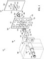
FIG. 1 is an exploded perspective view of an injection molding apparatus according to one embodiment. -
FIG. 2 is a front perspective view of a cavity flange of the injection molding apparatus ofFIG. 1 . -
FIG. 3 is a rear perspective view of the cavity flange ofFIG. 2 . -
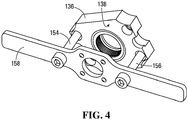
FIG. 4 is a front perspective view of the cavity flange ofFIG. 2 , also showing a tool that facilitates connecting and disconnecting the cavity flange. -
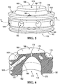
FIG. 5 is a perspective view of a gate insert of the injection molding apparatus ofFIG. 1 . -
FIG. 6 is a cross-sectional view of the gate insert ofFIG. 5 , taken along the line 6-6 inFIG. 5 . -
FIG. 7 is another perspective view of the gate insert ofFIG. 5 , also showing a tool that facilitates connecting and disconnecting the gate insert ofFIG. 5 . -
FIG. 8 is a perspective view of a gate pad of the injection molding apparatus ofFIG. 1 . -
FIG. 9 is a cross-sectional view of the gate pad ofFIG. 8 , taken along the line 9-9 inFIG. 8 . -
FIGS. 10-12 are cross-sectional views of the injection molding apparatus ofFIG. 1 partially assembled. -
FIG. 13 is a perspective view of the injection molding apparatus ofFIG. 1 assembled. -
FIG. 14 is a cross-sectional view of the injection molding apparatus ofFIG. 1 assembled as shown inFIG. 13 , taken along the line 14-14 inFIG. 13 . -
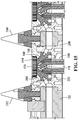
FIG. 15 is a cross-sectional view of the injection molding apparatus ofFIG. 1 assembled as shown inFIG. 13 , taken along the line 15-15 inFIG. 13 . -
FIG. 16 is a cross-sectional view of an injection molding apparatus according to another embodiment including a cavity flange different from the cavity flange ofFIG. 2 . - Referring to
FIG. 1 , an injection molding apparatus according to one embodiment is shown generally at 100. Theinjection molding apparatus 100 includes a hot runner assembly illustrated schematically and shown generally at 102, and a mold shown generally at 103. Themold 103 includes a cavity plate assembly shown generally at 104, and amovable mold assembly 105 that includes a movable stack assembly shown generally at 106 and arranged in a mold shoe. - The
hot runner assembly 102 includes amanifold plate 108 andinjection nozzles nozzle tip 118 of theinjection nozzle 112, for example) having at least one nozzle outlet (as described below with reference toFIGS. 14 and15 , for example), a fluid conduit extending through the injection nozzle and terminating at the at least one nozzle outlet (as also described below with reference toFIGS. 14 and15 , for example), and an outer sealing surface portion (such as a generally cylindrical outersealing surface portion 120 of theinjection nozzle 112, for example) surrounding a portion of the fluid conduit. - The
cavity plate assembly 104 includes acavity plate 122, which has a front side shown generally at 124 and a rear side shown generally at 126 and opposite thefront side 124. Thecavity plate 122 also defines gate openings shown generally at 128, 130, 132, and 134, each extending between, and open to, thefront side 124 and therear side 126. Further, the gate openings are aligned with respective nozzles such that when therear side 126 of thecavity plate 122 is mounted against themanifold plate 108, theinjection nozzle 110 is received in thegate opening 128, theinjection nozzle 112 is received in thegate opening 130, theinjection nozzle 114 is received in thegate opening 132, and theinjection nozzle 116 is received in thegate opening 134. Again, although the embodiment shown includes four gate openings, alternative embodiments may include more or fewer gate openings. - The
cavity plate assembly 104 also includes a molding body, which is acavity flange 136 in the embodiment shown. Thecavity flange 136 is a unitary structure that is made from a tool steel, although it may alternatively consist of a number of complementary parts and/or be made from other suitable materials known in the art. Referring toFIGS. 1-3 , thecavity flange 136 has a front side shown generally at 138 and a rear side shown generally at 140 and opposite thefront side 138. Thecavity flange 136 also defines a portion of a molding cavity shown generally at 142 and extending between, and open to, thefront side 138 and therear side 140. More specifically, thecavity flange 136 defines aperipheral surface 144 of the portion of themolding cavity 142 that molds, in use, a peripheral outer surface (i.e. shell) of a closure for a container, as described below. Thecavity flange 136 also defines threaded openings shown generally at 146, 148, 150, and 152 for receiving respective fasteners (not shown) to connect thecavity flange 136 to thefront side 124 of thecavity plate 122. Further, referring toFIG. 4 , the threaded openings may receivefasteners cavity flange 136 to atool 158 to facilitate connecting thecavity flange 136 to, and disconnecting thecavity flange 136 from, thefront side 124 of the cavity plate 122 (shown inFIG. 1 ). - Referring back to
FIG. 3 , on therear side 140, thecavity flange 136 includes a generallyannular abutment surface 159 including a taperedalignment surface 160, theabutment surface 159 also surrounding a portion of themolding cavity 142. The taperedalignment surface 160 may facilitate alignment of thecavity flange 136 while connecting thecavity flange 136 to thefront side 124 of the cavity plate 122 (shown inFIG. 1 ) as described below. Still referring toFIG. 3 , on therear side 140, thecavity flange 136 also defines cooling spaces (such as cooling spaces shown at 162 and 164 for example). - Referring back to
FIG. 1 , thecavity plate assembly 104 also includes a first injection gate body, which is agate insert 166 in the embodiment shown. Thegate insert 166 is a unitary structure that is made from a tool steel, although it may alternatively consist of a number of complementary parts and/or be made from other suitable materials known in the art. In the embodiment shown, thecavity flange 136 and thegate insert 166 are separate unitarily formed injection gate bodies, but in alternative embodiments thecavity flange 136 and thegate insert 166 may be a single unitarily formed injection gate body. - Referring to
FIGS. 1 ,5, and 6 , thegate insert 166 has a front side shown generally at 168 and a rear side shown generally at 170 and opposite thefront side 168. Thegate insert 166 defines an aperture shown generally at 172. Theaperture 172 extends through thegate insert 166 between an injection gate outlet, shown generally at 174 on thefirst side 168, and an opening shown generally at 176 on therear side 170 of thegate insert 166. Theaperture 172 is also sized to receive the nozzle tip 118 (shown inFIG. 1 ), as described below, such that melted plastic forced out of the fluid conduit of the injection nozzle 112 (also shown inFIG. 1 ) through the injection nozzle outlet at thenozzle tip 118 may be forced through theinjection gate outlet 174 and out thefront side 168 of thegate insert 166. - On the
front side 168, thegate insert 166 includes amolding surface 178 adjacent theinjection gate outlet 174. Themolding surface 178 defines a generally circular outer top surface of a closure for a container as described below. Also on thefront side 168, thegate insert 166 includes a generallyannular abutment surface 179 including a taperedalignment surface 180. Theabutment surface 179 is complementary to the abutment surface 159 (shown inFIG. 3 ), and more particularly the taperedalignment surface 180 is complementary to the tapered alignment surface 160 (also shown inFIG. 3 ) to facilitate aligning thecavity flange 136 to thegate insert 166 as described below. - On the
rear side 170, thegate insert 166 also includes a taperedalignment surface 181 and a generallyannular abutment surface 182 surrounding theopening 176 to theaperture 172. Theabutment surface 182 is generally planar, except that a recess shown generally at 183 in theabutment surface 182 defines a thermal insulation space as described below. - The
gate insert 166 also defines cooling fluid openings (such as cooling fluid openings shown generally at 184 and 185, for example), and fluid conduits open to respective cooling fluid openings (such as a coolingfluid conduit 186 open to the coolingfluid opening 184, for example) that direct cooling fluid to adjacent cooling fluid openings. For example, cooling fluid received in thegate insert 166 at the coolingfluid opening 185 may travel through the coolingfluid conduit 186 and then exit thegate insert 166 at the coolingfluid opening 184. - Referring to
FIGS. 5 and7 , on thefront side 168, thegate insert 166 also defines threaded openings shown generally at 188, 190, 192, and 194 for receiving threadedfasteners gate insert 166 to atool 204 to facilitate inserting thegate insert 166 in, and removing thegate insert 166 from, the gate opening 130 (shown inFIG. 1 ) in thecavity plate 122 or gate pad as described below. - Referring back to
FIG. 1 , thecavity plate assembly 104 also includes a second injection gate body, which is agate pad 206 in the embodiment shown. Thegate pad 206 is a unitary structure that is made from a tool steel, although it may alternatively consist of a number of complementary parts and/or be made from other suitable materials known in the art. Referring toFIGS. 8 and 9 , thegate pad 206 has a front side shown generally at 208, and a rear side shown generally at 210 and opposite thefront side 208. Thegate pad 206 defines an aperture shown generally at 216. Theaperture 216 extends through thegate pad 206 between an opening 213 on thefront side 208 of thegate pad 206 and an opening shown generally at 217 on therear side 210 of thegate pad 206. Thegate pad 206 includes a generallycylindrical wall 211 that defines a recess shown generally at 212 in theaperture 216 and sized to receive at least a portion of thegate insert 166 from theopening 213 on thefront side 208 of thegate pad 206 as described below. On thefront side 208, thegate pad 206 includes a taperedalignment surface 215 that cooperates with the tapered alignment surface 181 (shown inFIGS. 5 and 6 ) to facilitate aligning thegate insert 166 to thegate pad 206 as described below. - The
gate pad 206 also includes a generally cylindricalinner sealing surface 214 surrounding a portion of theaperture 216. Theinner sealing surface 214 is complementary to the outer sealing surface portion 120 (shown inFIG. 1 ) of theinjection nozzle 112 such that a portion of theinjection nozzle 112 may be received in theaperture 216 with the outersealing surface portion 120 of theinjection nozzle 112 in close contact with theinner sealing surface 214 of thegate pad 206 to form a seal between the outersealing surface portion 120 and theinner sealing surface 214. - The
gate pad 206 includes a generallyannular abutment surface 218 in therecess 212 and surrounding theaperture 216 on thefront side 208 of thegate pad 206. Theabutment surface 218 is positioned to abut theabutment surface 182 of thegate insert 166 when thegate insert 166 is received in therecess 212. Thegate pad 206 also defines cooling fluid openings shown generally at 220 and 222, and when thegate insert 166 is received in therecess 212 with theabutment surface 182 of thegate insert 166 abutted against theabutment surface 218 of thegate pad 206, the coolingfluid openings fluid openings FIG. 5 , for example) of thegate insert 166. Also, on therear side 210, thegate pad 206 includes aflange 224 positionable against the rear side 126 (shown inFIG. 1 ) of thecavity plate 122 when the generallycylindrical wall 211 of thegate pad 206 is received in the gate opening 130 (also shown inFIG. 1 ) of thecavity plate 122. - Referring back to
FIG. 1 , themovable stack assembly 106 includes astripper sleeve 226, anouter core 228, aninner core 230, and aslide 232. Theouter core 228, theinner core 230, and theslide 232 also include molding surfaces that define surfaces of a closure for a container, as described below. - Referring to
FIG. 10 , theinjection molding apparatus 100 may be assembled by inserting thegate pad 206 into thecavity plate 122 such that the generallycylindrical wall 211 is received in thegate opening 130 and theflange 224 is positioned in a recess of thecavity plate 122 on therear side 126 of thecavity plate 122, and therecess 212 of thegate pad 206 is open towards thefront side 124 of thecavity plate 122. Then, a portion of theinjection nozzle 112 may be inserted through theaperture 216 such that the outersealing surface portion 120 of theinjection nozzle 112 contacts, and forms a seal with, with theinner sealing surface 214, and such that thenozzle tip 118 extends into therecess 212. Avespel insulator 225 may be positioned around thenozzle tip 118 to insulate the space between thenozzle tip 118 and theaperture 172 with thegate insert 166 positioned in therecess 212. As shown with reference toFIG. 7 , thetool 204 may be employed to insert thegate insert 166 from thefront side 208 of thegate pad 206 and from thefront side 124 of thecavity plate 122. - Still referring to
FIG. 10 , if thegate insert 166 is not aligned with therecess 212 as thegate insert 166 is positioned in therecess 212, then the taperedalignment surface 181 on thegate insert 166 may contact the taperedalignment surface 215 on thegate pad 206 to facilitate aligning thegate insert 166 with therecess 212. The tapered alignment surfaces 181 and 215 are spaced apart from surfaces that define the molding cavity, so any damage to the tapered alignment surfaces 181 and 215 that may be caused by contact between the tapered alignment surfaces 181 and 215 may be spaced apart from surfaces that define the molding cavity. - When the
gate insert 166 is positioned in therecess 212, theabutment surface 182 of thegate insert 166 abuts theabutment surface 218 of thegate pad 206, as shown inFIG. 11 . Further, as shown inFIG. 11 , when thegate insert 166 is positioned in therecess 212 with theabutment surface 182 abutting theabutment surface 218, theinner sealing surface 214 of thegate pad 206 extends to an adjacent surface (theabutment surface 182 in the embodiment shown) of thegate insert 166, and themolding surface 178 of thegate insert 166 is substantially coplanar with afront surface 234 of thegate pad 206. In this context, "substantially coplanar" refers to surfaces that may not be perfectly coplanar, but that may function substantially similar to coplanar surfaces. - Further, as shown in
FIGS. 10 and 11 , thecavity plate 122 includes cooling fluid channels, such as cooling fluid channels shown generally at 236 and 238 for example, and as shown inFIG. 11 , when thegate insert 166 is positioned in therecess 212 with theabutment surface 182 of thegate insert 166 abutting theabutment surface 218 of thegate pad 206, the coolingfluid channels fluid openings FIG. 11 , when theabutment surface 182 of thegate insert 166 abuts theabutment surface 218 of thegate pad 206, therecess 183 in theabutment surface 182 defines a thermal insulation space shown generally at 240. Although thethermal insulation space 240 in the embodiment shown is formed by therecess 183 in thegate insert 166, one or more thermal insulation spaces in alternative embodiments may be formed by one or more surfaces of at least one of thegate insert 166 and thegate pad 206. - Referring to
FIGS. 11 and12 , thecavity flange 136 may be positioned on the front side of thegate insert 166, using the tool 158 (shown inFIG. 4 ) for example. If thecavity flange 136 is not aligned with thegate insert 166 as thecavity flange 136 is positioned on thefront side 168 of thegate insert 166, then the taperedalignment surface 160 of thecavity flange 136 may contact the taperedalignment surface 180 on thegate insert 166 to facilitate aligning thecavity flange 136 with thegate insert 166. The tapered alignment surfaces 160 and 180 are spaced apart from surfaces that define the molding cavity, so any damage to the tapered alignment surfaces 160 and 180 that may be caused by contact between the tapered alignment surfaces 160 and 180 may be spaced apart from surfaces that define the molding cavity. - The
cavity flange 136 may be connected to thefront side 124 of thecavity plate 122, and thus to thefront side 168 of thegate insert 166, using fasteners (not shown) through the threadedopenings FIGS. 2 and 3 ), and usingadditional retainers 242 and 244 (shown inFIGS. 13-15 ). More generally, thecavity flange 136 is connectable to, and disconnectable from, thecavity plate 122 from thefront side 124 of thecavity plate 122 and thegate insert 166 from thefront side 168 of thegate insert 166 without requiring separating thecavity plate 122 from themanifold plate 108 of the hot runner assembly 102 (for example by "latching over" thecavity plate 122 to the shoe (not shown) that retains the movable stack assembly 106), and more generally without requiring removal of any components of theinjection molding apparatus 100. In other words, theinjection molding apparatus 100 is free from any structure that would prevent thecavity flange 136 from being connectable to, or disconnectable from, thecavity plate 122 from thefront side 124 of thecavity plate 122 and thegate insert 166 from thefront side 168 of thegate insert 166. - Further, as shown in
FIG. 12 , when thecavity flange 136 is positioned on the front side of thegate insert 166, theabutment surface 159 on thecavity flange 136 abuts theabutment surface 179 on thegate insert 166. Therefore, when thecavity flange 136 is connected (in a connected position shown inFIG. 12 ) to thefront side 124 of thecavity plate 122, thecavity flange 136 retains thegate insert 166 within thegate pad 206. More generally, thegate insert 166 is connectable to, and disconnectable from, thecavity plate 122 from thefront side 124 of thecavity plate 122 and thefront side 208 of thegate pad 206 without requiring separating thecavity plate 122 from themanifold plate 108 of the hot runner assembly 102 (for example by "latching over" thecavity plate 122 to the shoe (not shown) that retains the movable stack assembly 106), and more generally without requiring removal of any components (other than the cavity flange 136) from theinjection molding apparatus 100. In the embodiment shown, thegate insert 166 is connectable to thegate pad 206 from thefront side 208 of thegate pad 206 when at least a portion of thegate insert 166 is received in therecess 212 of thegate pad 206. Further, thegate insert 166 is connectable to, and disconnectable from, thecavity plate 122 from thefront side 124 of thecavity plate 122 and thefront side 208 of thegate pad 206 without requiring removal of any components (other than the cavity flange 136) from theinjection molding apparatus 100. In other words, when thecavity flange 136 is disconnected from thefront side 124 of thecavity plate 122 and thefront side 168 of thegate insert 166, theinjection molding apparatus 100 is free from any structure that would prevent thegate insert 166 from being connectable to, or disconnectable from, thecavity plate 122 from thefront side 124 of thecavity plate 122 and thegate pad 206 from thefront side 208 of thegate pad 206. - Referring to
FIG. 13 , once theinjection molding apparatus 100 is assembled as shown inFIGS. 10-12 and with closing of themold 103, theperipheral surface 144 of thecavity flange 136, themolding surface 178 of thegate insert 166, and amolding surface 248 of theslide 232 collectively define an outer surface of a closure for a container, and amolding surface 246 defined on theinner core 230 and theouter core 228 defines inner surfaces of the closure. Therefore, when thecavity flange 136 is connected (in the connected position shown inFIG. 12 ) to thefront side 124 of thecavity plate 122, thecavity flange 136 defines a portion of a molding cavity (shaped to mold an outer surface of a shell of a closure for a container in the embodiment shown), and themolding surface 178 of thegate insert 166 also defines a portion of such a molding cavity (shaped to mold a top surface of a top panel of a closure for a container in the embodiment shown). - Referring to
FIGS. 14 and15 , theinjection nozzle 112 is shown in greater detail and includes anozzle housing 249 and a fluid conduit shown generally at 250. Thefluid conduit 250 extends through theinjection nozzle 112 and terminates at nozzle outlets shown generally at 252 and 254 (or, more generally, at least one nozzle outlet) in thenozzle tip 118. The outersealing surface portion 120 is on thenozzle housing 249, surrounds a portion of thefluid conduit 250, and contacts theinner sealing surface 214 of thegate pad 206 when a portion of the injection nozzle having the outersealing surface portion 120 is received in theaperture 216. Thenozzle tip 118 extends forward (namely in a direction towards thefront sides sealing surface portion 120 and may be connectable to and disconnectable from thenozzle housing 249. - As shown in
FIGS. 14 and15 , when thegate insert 166 is received in thegate pad 206, theaperture 172 of thegate insert 166 accommodates at least a front portion of thenozzle tip 118 therein with thenozzle outlets injection gate outlet 174. Further, theinjection nozzle 112 does not contact the gate insert 166 (except indirectly through the vespel insulator 225) and theinjection nozzle 112 is spaced apart from thegate insert 166. - As indicated above, the
molding surface 178 of thegate insert 166 defines a generally circular outer top surface (i.e. top panel) of a closure for a container, and the outer top surface of such a closure may include text, logos, or other shapes or images defined by themolding surface 178. Therefore, such text, logos, or other shapes or images on the outer top surface of such a closure may be changed by substituting a different gate insert for thegate insert 166, and because thegate insert 166 is connectable to, and disconnectable from, thecavity plate 122 and thegate pad 206 without requiring separating thecavity plate 122 from thehot runner assembly 102 and without requiring removal of any components (other than the cavity flange 136) from theinjection molding apparatus 100 as indicated above, such text, logos, or other shapes or images on the outer top surface of such a closure may be changed more easily or efficiently, or for lower cost, than in other injection molding apparatuses. - Further, other characteristics of such a closure may be changed more easily or efficiently, or for lower cost, than in other injection molding apparatuses. For example, referring to
FIG. 16 , an injection molding apparatus according to another embodiment is shown generally at 256 and includes thecavity plate 122, thegate insert 166, and thegate pad 206 assembled as described above, but includes a different molding body, which in the embodiment shown is a unitarily formedcavity flange 258. Thecavity flange 258 includes aperipheral surface 260 that defines a portion of a molding cavity shown generally at 262 that molds, in use, a peripheral outer surface (i.e. shell) of the closure, and thecavity flange 258 is similar to thecavity flange 136 described above, but theperipheral surface 260 has aheight 263 that differs from a height 264 (shown inFIG. 15 ) of theperipheral surface 144 of thecavity flange 136. Therefore, by replacing thecavity flange 136 with another cavity flange such as thecavity flange 258, the height (or other characteristics of the peripheral outer surface of a closure) may be changed more easily or efficiently, or for lower cost, than in other injection molding apparatuses. - Also, because the
cavity flange 136 and thegate insert 166 are both connectable to, and disconnectable from, thecavity plate 122 and thegate pad 206 without requiring separating thecavity plate 122 from thehot runner assembly 102 and without requiring removal of any components (other than the cavity flange 136) from theinjection molding apparatus 100 as indicated above, cleaning one or more of thecavity flange 136, thegate insert 166, and therecess 212, and servicing the portion of the injection nozzle 112 (such as the nozzle tip 118) that extends to the front side of theabutment surface 218, may be easier or more efficient, or may involve a lower cost, than in other injection molding apparatuses. - Further, as indicated above and shown in
FIGS. 11-15 , the outer sealing surface portion 120 (shown inFIG. 1 ) of theinjection nozzle 112 forms a seal with theinner sealing surface 214 of thegate pad 206, which does not form any portion of the molding cavity, and theinjection nozzle 112 does not form a seal with thegate insert 166, which does form a portion the molding cavity. Therefore, the outer sealing surface portion 120 (shown inFIG. 1 ) of theinjection nozzle 112 forms a seal with an injection gate body different from an injection gate body that forms a portion the molding cavity, which may reduce transmission of heat from theheated injection nozzle 112 to the cooled molding cavity, and which may thus reduce waste of heat and conserve energy. In the embodiment shown, thethermal insulation space 240 may further reduce waste of heat and conserve energy. - The present invention further pertains to:
- 1. An injection molding apparatus (100) comprising:
- a first injection gate body (166) having front (168) and rear (170) opposite sides and a first aperture (172) extending through the first injection gate body between an injection gate outlet (174) on the front side of the first injection gate body and an opening (176) on the rear side of the first injection gate body; and
- a second injection gate body (206) having front (208) and rear (210) opposite sides and a second aperture (216) extending through the second injection gate body between an opening (213) on the front side of the second injection gate body and an opening (217) on the rear side of the second injection gate body, the second injection gate body comprising an inner sealing surface (214) defining at least a portion of the second aperture (216) and complementary to an outer sealing surface portion (120) of an injection nozzle (112) such that, when a portion of the injection nozzle is received in the second aperture (216), the outer sealing surface portion of the injection nozzle contacts the inner sealing surface (214) of the second injection gate body (206) to form a seal between the outer sealing surface portion (120) of the injection nozzle (112) and the inner sealing surface (214) of the second injection gate body (206),
wherein the first injection gate body (166) is connectable to and disconnectable from the second injection gate body (206) from the front side (208) of the second injection gate body such that, when the rear side (170) of the first injection gate body (166) is connected in a connected position to the front side of the second injection gate body, the first aperture (172) is adjacent the second aperture (216) to permit the first aperture to receive at least a front portion of a nozzle tip (118) of the injection nozzle (112) with at least one nozzle outlet (252, 254) of the nozzle tip positioned to inject fluid through the injection gate outlet (174) when the portion of the injection nozzle is received in the second aperture (216).
- 2. The apparatus of item 1 further comprising a molding body (136) connectable to and disconnectable from the first injection gate body (166) from the front side (168) of the first injection gate body wherein, when the molding body (136) is connected in a connected position to the front side (168) of the first injection gate body (166), the molding body defines at least a portion of a molding cavity.
- 3. The apparatus of item 2, wherein, when the molding body (136) is connected in the connected position to the front side (168) of the first injection gate body (166), the molding body and a molding surface (178) on the front side (168) of the first injection gate body (166) define at least a portion of the molding cavity.
- 4. The apparatus of item 2, wherein the first injection gate body is a gate insert (166) that defines a top panel of a closure for a container, and wherein the molding body is a cavity flange (136) that defines a shell of the closure.
- 5. The apparatus of item 4, wherein the second injection gate body is a gate pad (206) that is configured to be received in a cavity plate (122) of a cavity assembly (104).
- 6. The apparatus of item 5,wherein the second injection gate body (206) defines a recess (212) sized to receive at least a portion of the first injection gate body (166), and wherein the gate insert (166) is connectable to the gate pad (206) from the front side (208) of the gate pad when the at least a portion of the gate insert is inserted in the recess (212).
- 7. The apparatus of item 1, wherein the second injection gate body (206) defines a recess (212) sized to receive at least a portion of the first injection gate body (166), and wherein the first injection gate body (166) is connectable to the second injection gate body (206) from the front side (208) of the second injection gate body when the at least a portion of the first injection gate body is inserted in the recess (212).
- 8. The apparatus of item 1, wherein the outer sealing surface portion (120) of the injection nozzle (118) and the inner sealing surface (214) of the second injection gate body (206) are generally cylindrical.
- 9. The apparatus of item 1, wherein at least one of the first injection gate body (166) and the second injection gate body (206) defines at least one thermal insulation space (240) between at least one surface (182) of the first injection gate body (166) and at least one surface (218) of the second injection gate body (206) that are adjacent when the first injection gate body is connected in the connected position to the front side (208) of the second injection gate body.
- 10. The apparatus of item 9, wherein:
- the first injection gate body (166) defines a first abutment surface (182) on the rear side (170) of the first injection gate body and surrounding the opening (176) on the rear side of the first injection gate body;
- the second injection gate body (206) defines a second abutment surface (218) on the front side (208) of the second injection gate body and surrounding the opening (213) on the front side of the second injection gate body; and
- when the first injection gate body (166) is connected in the connected position to the front side (208) of the second injection gate body (206), the first abutment surface (182) abuts the second abutment surface (218) to form a seal between the first abutment surface and the second abutment surface, and the thermal insulation space (240) is defined between the first abutment surface (182) and the second abutment surface (218).
- 11. The apparatus of item 1 further comprising the injection nozzle (112), wherein the injection nozzle comprises a fluid conduit (250) extending through the injection nozzle (112) and terminating at the at least one nozzle outlet (252, 254), and wherein the outer sealing surface portion (120) surrounds a portion of the fluid conduit (250).
- 12. The apparatus of item 11, wherein, when the portion of the injection nozzle (112) is received in the second aperture (216), the injection nozzle (112) is spaced apart from the first injection gate body (166).
- 13. A gate insert (166) comprising:
- an injection gate body having front (168) and rear (170) opposite sides and an aperture (172) extending through the injection gate body between an injection gate outlet (174) on the front side of the injection gate body and an opening (176) on the rear side of the injection gate body,
- wherein the injection gate body is connectable to and disconnectable from a gate pad (206) in a cavity plate (122) from a front side (208) of the gate pad (206) and from a front side (124) of the cavity plate (122).
- 14. The gate insert of item 13, wherein the injection gate body has a tapered alignment surface (180) on the rear side (170) of the injection gate body to facilitate aligning the injection gate body with the gate pad (206).
- 15. The gate insert of item 13, wherein the injection gate body has a molding surface (178) on the front side (168) of the injection gate body that defines a top panel of a closure for a container.
- 16. A cavity flange (136) comprising:
- a molding body defining at least a portion of a molding cavity shaped to mold a shell of a closure for a container,
- wherein the molding body is connectable to and disconnectable from a gate insert (166) in a cavity plate (122) from a front side (168) of the gate insert and from a front side (124) of the cavity plate.
- 17. The cavity flange of item 16, wherein the molding body has a tapered alignment surface (160) on the rear side (140) of the molding body to facilitate aligning the molding body with the gate insert (166).
Claims (6)
- An injection molding apparatus (100) for use in a cavity plate assembly (104), the apparatus comprising:a first injection gate body (166) having front (168) and rear (170) opposite sides and a first aperture (172) extending through the first injection gate body between an injection gate outlet (174) on the front side of the first injection gate body and an opening (176) on the rear side of the first injection gate body; anda first molding body (136) connectable to and disconnectable from the first injection gate body (166) from the front side (168) of the first injection gate body and the cavity plate assembly (104) from a front side (124) of the cavity plate assembly, wherein the first molding body (136) defines at least a portion of a first molding cavity shaped to mold at least a portion of a closure for a container,wherein, when the first molding body (136) is disconnected from the front side (168) of the first injection gate body (166) and from the cavity plate assembly (104), the apparatus (100) is free from any structure that would prevent the first injection gate body (166) from being connectable to or disconnectable from the cavity plate assembly (104) from the front side (124) of the cavity plate assembly.
- The apparatus of claim 1 further comprising the cavity plate assembly (104).
- The apparatus of claim 1, wherein, when the first molding body (136) is connected to the front side (168) of the first injection gate body (166), the first molding body (136) and a molding surface (178) on the front side (168) of the first injection gate body (166) define at least a portion of the first molding cavity.
- The apparatus of claim 1 further comprising a second injection gate body (206) having front (208) and rear (210) opposite sides and a second aperture (216) extending through the second injection gate body between an opening (213) on the front side of the second injection gate body and an opening (217) on the rear side of the second injection gate body, wherein the first injection gate body (166) is connectable to and disconnectable from the second injection gate body (206) from the front side (208) of the second injection gate body such that, when the rear side (170) of the first injection gate body (166) is connected in a connected position to the front side (208) of the second injection gate body (206), the first aperture (172) is adjacent the second aperture (216).
- The apparatus of claim 4, wherein the second injection gate body (206) comprises a front surface (234) on the front side (208) of the second injection gate body and substantially coplanar with the molding surface (178) on the front side (168) of the first injection gate body (166) when the first injection gate body is connected in the connected position to the front side (208) of the second injection gate body (206).
- The apparatus of claim 1 further comprising a second molding body (258) connectable to and disconnectable from the first injection gate body (166) from the front side (168) of the first injection gate body and the cavity plate assembly (104) from the front side (124) of the cavity plate assembly, wherein the second molding body defines at least a portion of a second molding cavity shaped to mold at least a portion of a closure, for a container, having a height (263) different from a height (264) of the at least a portion of the closure defined by the first molding body (136).
Applications Claiming Priority (3)
| Application Number | Priority Date | Filing Date | Title |
|---|---|---|---|
| US201562189827P | 2015-07-08 | 2015-07-08 | |
| PCT/CA2016/050616 WO2017004697A1 (en) | 2015-07-08 | 2016-06-01 | Injection molding apparatuses |
| EP16820588.8A EP3319776B1 (en) | 2015-07-08 | 2016-06-01 | Injection molding apparatuses |
Related Parent Applications (2)
| Application Number | Title | Priority Date | Filing Date |
|---|---|---|---|
| EP16820588.8A Division EP3319776B1 (en) | 2015-07-08 | 2016-06-01 | Injection molding apparatuses |
| EP16820588.8A Division-Into EP3319776B1 (en) | 2015-07-08 | 2016-06-01 | Injection molding apparatuses |
Publications (2)
| Publication Number | Publication Date |
|---|---|
| EP3424676A1 true EP3424676A1 (en) | 2019-01-09 |
| EP3424676B1 EP3424676B1 (en) | 2021-04-14 |
Family
ID=57684655
Family Applications (3)
| Application Number | Title | Priority Date | Filing Date |
|---|---|---|---|
| EP18185884.6A Active EP3424676B1 (en) | 2015-07-08 | 2016-06-01 | Injection molding apparatus |
| EP21189178.3A Pending EP3936301A1 (en) | 2015-07-08 | 2016-06-01 | Injection molding apparatuses |
| EP16820588.8A Active EP3319776B1 (en) | 2015-07-08 | 2016-06-01 | Injection molding apparatuses |
Family Applications After (2)
| Application Number | Title | Priority Date | Filing Date |
|---|---|---|---|
| EP21189178.3A Pending EP3936301A1 (en) | 2015-07-08 | 2016-06-01 | Injection molding apparatuses |
| EP16820588.8A Active EP3319776B1 (en) | 2015-07-08 | 2016-06-01 | Injection molding apparatuses |
Country Status (7)
| Country | Link |
|---|---|
| US (2) | US10773436B2 (en) |
| EP (3) | EP3424676B1 (en) |
| CN (1) | CN108602223B (en) |
| CA (1) | CA2989900C (en) |
| ES (1) | ES2880180T3 (en) |
| PT (1) | PT3424676T (en) |
| WO (1) | WO2017004697A1 (en) |
Families Citing this family (3)
| Publication number | Priority date | Publication date | Assignee | Title |
|---|---|---|---|---|
| CN108602223B (en) * | 2015-07-08 | 2020-12-01 | 赫斯基注塑系统有限公司 | Injection molding device |
| KR102586810B1 (en) * | 2018-12-11 | 2023-10-10 | 허스키 인젝션 몰딩 시스템즈 리미티드 | Molds, mold assemblies and stack components |
| WO2025233191A1 (en) | 2024-05-06 | 2025-11-13 | Z-Moulds Gmbh | Plastics injection moulding tool and fitting tool for fitting a mould cavity part into and/or removing the mould cavity part from a mould plate of a plastics injection moulding tool |
Citations (2)
| Publication number | Priority date | Publication date | Assignee | Title |
|---|---|---|---|---|
| US6569370B1 (en) * | 2000-05-25 | 2003-05-27 | Husky Injection Molding System Ltd. | Injection molding system and method using cavity flange and neck ring insert |
| US20080268089A1 (en) * | 2007-04-29 | 2008-10-30 | Kmoch Sven | Mold Assembly Using Inserts |
Family Cites Families (20)
| Publication number | Priority date | Publication date | Assignee | Title |
|---|---|---|---|---|
| US3677682A (en) | 1970-03-09 | 1972-07-18 | Ladislao Wladyslaw Putkowski | Hot runner system |
| ES2069567T3 (en) * | 1988-12-05 | 1995-05-16 | Mold Masters Ltd | INJECTION MOLDING APPARATUS WITH LIQUID COOLED INSERTS. |
| US5262116A (en) | 1992-05-05 | 1993-11-16 | Von Holdt Sr John | Modular molding system |
| CA2228931C (en) * | 1998-02-02 | 2007-06-26 | Mold-Masters Limited | Injection molding three portion gate and cavity insert |
| US6390800B1 (en) * | 2000-06-01 | 2002-05-21 | Unique Mould Makers Limited | Apparatus for removing threaded parts from plastic injection molds |
| DE10037739B4 (en) | 2000-08-02 | 2004-02-26 | Siemens Ag | Hot runner nozzle for an injection mold |
| US6450797B1 (en) | 2001-03-01 | 2002-09-17 | Stackteck Systems Limited | Compact slide actuation mold |
| US6863521B2 (en) * | 2002-11-26 | 2005-03-08 | Nicoleon Petrou | Translation device for an injection molding apparatus |
| US7306454B2 (en) | 2003-04-07 | 2007-12-11 | Mold-Masters Limited | Front-mountable injection molding nozzle |
| JP4369381B2 (en) | 2005-02-24 | 2009-11-18 | 株式会社名機製作所 | Disk substrate molding die and disk substrate molding method |
| DE102006021228A1 (en) * | 2006-05-06 | 2007-11-08 | Mht Mold & Hotrunner Technology Ag | Two-piece ground insert |
| US20080206396A1 (en) | 2007-02-27 | 2008-08-28 | Husky Injection Molding Systems Ltd. | Hot Runner System with Composite Nozzle Tip |
| US7628605B2 (en) | 2007-07-20 | 2009-12-08 | Husky Injection Molding Systems Ltd. | Mold stack |
| CA2755908C (en) | 2009-04-24 | 2013-05-28 | Husky Injection Molding Systems Ltd. | A cavity insert for a molding system, the cavity insert having a deformable portion |
| CN102470585A (en) | 2009-08-17 | 2012-05-23 | 赫斯基注塑系统有限公司 | Molding apparatus |
| US8834149B2 (en) | 2010-04-23 | 2014-09-16 | Husky Injection Molding Systems Ltd. | Molding apparatus |
| KR101313867B1 (en) * | 2011-06-07 | 2013-10-01 | 양형택 | manufacturing apparatus of forming material having a inner screw |
| US9254598B2 (en) * | 2012-03-29 | 2016-02-09 | Husky Infection Molding Systems Ltd. | Mold stack having an air valve |
| US9272453B1 (en) | 2014-08-29 | 2016-03-01 | Husky Injection Molding Systems Ltd. | Hot runner with removable gate pad |
| CN108602223B (en) * | 2015-07-08 | 2020-12-01 | 赫斯基注塑系统有限公司 | Injection molding device |
-
2016
- 2016-06-01 CN CN201680035889.4A patent/CN108602223B/en active Active
- 2016-06-01 PT PT181858846T patent/PT3424676T/en unknown
- 2016-06-01 EP EP18185884.6A patent/EP3424676B1/en active Active
- 2016-06-01 WO PCT/CA2016/050616 patent/WO2017004697A1/en not_active Ceased
- 2016-06-01 CA CA2989900A patent/CA2989900C/en active Active
- 2016-06-01 EP EP21189178.3A patent/EP3936301A1/en active Pending
- 2016-06-01 ES ES18185884T patent/ES2880180T3/en active Active
- 2016-06-01 US US15/737,508 patent/US10773436B2/en active Active
- 2016-06-01 EP EP16820588.8A patent/EP3319776B1/en active Active
-
2020
- 2020-04-08 US US16/843,310 patent/US11225002B2/en active Active
Patent Citations (2)
| Publication number | Priority date | Publication date | Assignee | Title |
|---|---|---|---|---|
| US6569370B1 (en) * | 2000-05-25 | 2003-05-27 | Husky Injection Molding System Ltd. | Injection molding system and method using cavity flange and neck ring insert |
| US20080268089A1 (en) * | 2007-04-29 | 2008-10-30 | Kmoch Sven | Mold Assembly Using Inserts |
Also Published As
| Publication number | Publication date |
|---|---|
| CN108602223A (en) | 2018-09-28 |
| ES2880180T3 (en) | 2021-11-23 |
| EP3319776A1 (en) | 2018-05-16 |
| PT3424676T (en) | 2021-07-02 |
| US20200230855A1 (en) | 2020-07-23 |
| EP3424676B1 (en) | 2021-04-14 |
| EP3319776B1 (en) | 2022-02-23 |
| CA2989900A1 (en) | 2017-01-12 |
| WO2017004697A1 (en) | 2017-01-12 |
| US10773436B2 (en) | 2020-09-15 |
| EP3319776A4 (en) | 2019-08-07 |
| US20180178427A1 (en) | 2018-06-28 |
| CA2989900C (en) | 2021-08-10 |
| EP3936301A1 (en) | 2022-01-12 |
| US11225002B2 (en) | 2022-01-18 |
| CN108602223B (en) | 2020-12-01 |
Similar Documents
| Publication | Publication Date | Title |
|---|---|---|
| US11225002B2 (en) | Injection molding apparatuses | |
| KR101145952B1 (en) | Mold insert and mold stack for use with molding machine | |
| US7794228B2 (en) | Injection molding apparatus having an edge-gated runnerless nozzle | |
| RU2365500C1 (en) | Split insert of die | |
| CN103097102B (en) | molding equipment | |
| US7568906B2 (en) | Mold assembly using inserts | |
| US20140363534A1 (en) | Side Gate Nozzle Assembly | |
| US7566216B2 (en) | Mold assembly using inserts | |
| US20040137106A1 (en) | Nozzle for injection mold | |
| KR101331538B1 (en) | Injection nozzle, in particular hot-runner nozzle, for arrangement in an injection mould | |
| EP0583652A1 (en) | Injection molding nozzle insert | |
| CN107949468B (en) | Separate locking device and injection molding mold using the same | |
| US11077595B2 (en) | Side-gate injection molding apparatus and side-gate nozzle assembly | |
| US7134637B2 (en) | Vacuum and vent block for use with molding and casting systems | |
| KR20130030756A (en) | A retaining member for use with a molding system and the molding system incorporating same | |
| US20150367546A1 (en) | Hot runner apparatus for an injection molding machine | |
| JPH043776Y2 (en) |
Legal Events
| Date | Code | Title | Description |
|---|---|---|---|
| PUAI | Public reference made under article 153(3) epc to a published international application that has entered the european phase |
Free format text: ORIGINAL CODE: 0009012 |
|
| STAA | Information on the status of an ep patent application or granted ep patent |
Free format text: STATUS: THE APPLICATION HAS BEEN PUBLISHED |
|
| AC | Divisional application: reference to earlier application |
Ref document number: 3319776 Country of ref document: EP Kind code of ref document: P |
|
| AK | Designated contracting states |
Kind code of ref document: A1 Designated state(s): AL AT BE BG CH CY CZ DE DK EE ES FI FR GB GR HR HU IE IS IT LI LT LU LV MC MK MT NL NO PL PT RO RS SE SI SK SM TR |
|
| STAA | Information on the status of an ep patent application or granted ep patent |
Free format text: STATUS: REQUEST FOR EXAMINATION WAS MADE |
|
| 17P | Request for examination filed |
Effective date: 20190709 |
|
| RBV | Designated contracting states (corrected) |
Designated state(s): AL AT BE BG CH CY CZ DE DK EE ES FI FR GB GR HR HU IE IS IT LI LT LU LV MC MK MT NL NO PL PT RO RS SE SI SK SM TR |
|
| STAA | Information on the status of an ep patent application or granted ep patent |
Free format text: STATUS: EXAMINATION IS IN PROGRESS |
|
| 17Q | First examination report despatched |
Effective date: 20200204 |
|
| GRAP | Despatch of communication of intention to grant a patent |
Free format text: ORIGINAL CODE: EPIDOSNIGR1 |
|
| STAA | Information on the status of an ep patent application or granted ep patent |
Free format text: STATUS: GRANT OF PATENT IS INTENDED |
|
| RIC1 | Information provided on ipc code assigned before grant |
Ipc: B29L 31/56 20060101ALN20200904BHEP Ipc: B29C 45/27 20060101AFI20200904BHEP Ipc: B29C 45/26 20060101ALI20200904BHEP |
|
| INTG | Intention to grant announced |
Effective date: 20201005 |
|
| GRAS | Grant fee paid |
Free format text: ORIGINAL CODE: EPIDOSNIGR3 |
|
| RAP1 | Party data changed (applicant data changed or rights of an application transferred) |
Owner name: HUSKY INJECTION MOLDING SYSTEMS LUXEMBOURG IP DEVELOPMENT S.A.R.L |
|
| GRAA | (expected) grant |
Free format text: ORIGINAL CODE: 0009210 |
|
| STAA | Information on the status of an ep patent application or granted ep patent |
Free format text: STATUS: THE PATENT HAS BEEN GRANTED |
|
| RAP1 | Party data changed (applicant data changed or rights of an application transferred) |
Owner name: HUSKY INJECTION MOLDING SYSTEMS LTD. |
|
| AC | Divisional application: reference to earlier application |
Ref document number: 3319776 Country of ref document: EP Kind code of ref document: P |
|
| AK | Designated contracting states |
Kind code of ref document: B1 Designated state(s): AL AT BE BG CH CY CZ DE DK EE ES FI FR GB GR HR HU IE IS IT LI LT LU LV MC MK MT NL NO PL PT RO RS SE SI SK SM TR |
|
| REG | Reference to a national code |
Ref country code: GB Ref legal event code: FG4D |
|
| REG | Reference to a national code |
Ref country code: CH Ref legal event code: EP |
|
| REG | Reference to a national code |
Ref country code: DE Ref legal event code: R096 Ref document number: 602016056328 Country of ref document: DE |
|
| REG | Reference to a national code |
Ref country code: IE Ref legal event code: FG4D |
|
| REG | Reference to a national code |
Ref country code: AT Ref legal event code: REF Ref document number: 1381936 Country of ref document: AT Kind code of ref document: T Effective date: 20210515 |
|
| REG | Reference to a national code |
Ref country code: PT Ref legal event code: SC4A Ref document number: 3424676 Country of ref document: PT Date of ref document: 20210702 Kind code of ref document: T Free format text: AVAILABILITY OF NATIONAL TRANSLATION Effective date: 20210625 |
|
| REG | Reference to a national code |
Ref country code: SE Ref legal event code: TRGR |
|
| REG | Reference to a national code |
Ref country code: NL Ref legal event code: FP |
|
| PGFP | Annual fee paid to national office [announced via postgrant information from national office to epo] |
Ref country code: NL Payment date: 20210618 Year of fee payment: 6 Ref country code: PT Payment date: 20210628 Year of fee payment: 6 |
|
| REG | Reference to a national code |
Ref country code: LT Ref legal event code: MG9D |
|
| PGFP | Annual fee paid to national office [announced via postgrant information from national office to epo] |
Ref country code: SE Payment date: 20210630 Year of fee payment: 6 |
|
| PG25 | Lapsed in a contracting state [announced via postgrant information from national office to epo] |
Ref country code: BG Free format text: LAPSE BECAUSE OF FAILURE TO SUBMIT A TRANSLATION OF THE DESCRIPTION OR TO PAY THE FEE WITHIN THE PRESCRIBED TIME-LIMIT Effective date: 20210714 Ref country code: HR Free format text: LAPSE BECAUSE OF FAILURE TO SUBMIT A TRANSLATION OF THE DESCRIPTION OR TO PAY THE FEE WITHIN THE PRESCRIBED TIME-LIMIT Effective date: 20210414 Ref country code: LT Free format text: LAPSE BECAUSE OF FAILURE TO SUBMIT A TRANSLATION OF THE DESCRIPTION OR TO PAY THE FEE WITHIN THE PRESCRIBED TIME-LIMIT Effective date: 20210414 Ref country code: FI Free format text: LAPSE BECAUSE OF FAILURE TO SUBMIT A TRANSLATION OF THE DESCRIPTION OR TO PAY THE FEE WITHIN THE PRESCRIBED TIME-LIMIT Effective date: 20210414 |
|
| PGFP | Annual fee paid to national office [announced via postgrant information from national office to epo] |
Ref country code: CZ Payment date: 20210603 Year of fee payment: 6 |
|
| REG | Reference to a national code |
Ref country code: ES Ref legal event code: FG2A Ref document number: 2880180 Country of ref document: ES Kind code of ref document: T3 Effective date: 20211123 |
|
| PG25 | Lapsed in a contracting state [announced via postgrant information from national office to epo] |
Ref country code: RS Free format text: LAPSE BECAUSE OF FAILURE TO SUBMIT A TRANSLATION OF THE DESCRIPTION OR TO PAY THE FEE WITHIN THE PRESCRIBED TIME-LIMIT Effective date: 20210414 Ref country code: LV Free format text: LAPSE BECAUSE OF FAILURE TO SUBMIT A TRANSLATION OF THE DESCRIPTION OR TO PAY THE FEE WITHIN THE PRESCRIBED TIME-LIMIT Effective date: 20210414 Ref country code: NO Free format text: LAPSE BECAUSE OF FAILURE TO SUBMIT A TRANSLATION OF THE DESCRIPTION OR TO PAY THE FEE WITHIN THE PRESCRIBED TIME-LIMIT Effective date: 20210714 Ref country code: PL Free format text: LAPSE BECAUSE OF FAILURE TO SUBMIT A TRANSLATION OF THE DESCRIPTION OR TO PAY THE FEE WITHIN THE PRESCRIBED TIME-LIMIT Effective date: 20210414 Ref country code: IS Free format text: LAPSE BECAUSE OF FAILURE TO SUBMIT A TRANSLATION OF THE DESCRIPTION OR TO PAY THE FEE WITHIN THE PRESCRIBED TIME-LIMIT Effective date: 20210814 Ref country code: GR Free format text: LAPSE BECAUSE OF FAILURE TO SUBMIT A TRANSLATION OF THE DESCRIPTION OR TO PAY THE FEE WITHIN THE PRESCRIBED TIME-LIMIT Effective date: 20210715 |
|
| PGFP | Annual fee paid to national office [announced via postgrant information from national office to epo] |
Ref country code: ES Payment date: 20210701 Year of fee payment: 6 |
|
| REG | Reference to a national code |
Ref country code: DE Ref legal event code: R097 Ref document number: 602016056328 Country of ref document: DE |
|
| PG25 | Lapsed in a contracting state [announced via postgrant information from national office to epo] |
Ref country code: SK Free format text: LAPSE BECAUSE OF FAILURE TO SUBMIT A TRANSLATION OF THE DESCRIPTION OR TO PAY THE FEE WITHIN THE PRESCRIBED TIME-LIMIT Effective date: 20210414 Ref country code: SM Free format text: LAPSE BECAUSE OF FAILURE TO SUBMIT A TRANSLATION OF THE DESCRIPTION OR TO PAY THE FEE WITHIN THE PRESCRIBED TIME-LIMIT Effective date: 20210414 Ref country code: EE Free format text: LAPSE BECAUSE OF FAILURE TO SUBMIT A TRANSLATION OF THE DESCRIPTION OR TO PAY THE FEE WITHIN THE PRESCRIBED TIME-LIMIT Effective date: 20210414 Ref country code: RO Free format text: LAPSE BECAUSE OF FAILURE TO SUBMIT A TRANSLATION OF THE DESCRIPTION OR TO PAY THE FEE WITHIN THE PRESCRIBED TIME-LIMIT Effective date: 20210414 Ref country code: MC Free format text: LAPSE BECAUSE OF FAILURE TO SUBMIT A TRANSLATION OF THE DESCRIPTION OR TO PAY THE FEE WITHIN THE PRESCRIBED TIME-LIMIT Effective date: 20210414 Ref country code: DK Free format text: LAPSE BECAUSE OF FAILURE TO SUBMIT A TRANSLATION OF THE DESCRIPTION OR TO PAY THE FEE WITHIN THE PRESCRIBED TIME-LIMIT Effective date: 20210414 |
|
| PLBE | No opposition filed within time limit |
Free format text: ORIGINAL CODE: 0009261 |
|
| STAA | Information on the status of an ep patent application or granted ep patent |
Free format text: STATUS: NO OPPOSITION FILED WITHIN TIME LIMIT |
|
| REG | Reference to a national code |
Ref country code: BE Ref legal event code: MM Effective date: 20210630 |
|
| 26N | No opposition filed |
Effective date: 20220117 |
|
| PG25 | Lapsed in a contracting state [announced via postgrant information from national office to epo] |
Ref country code: IE Free format text: LAPSE BECAUSE OF NON-PAYMENT OF DUE FEES Effective date: 20210601 |
|
| PG25 | Lapsed in a contracting state [announced via postgrant information from national office to epo] |
Ref country code: IS Free format text: LAPSE BECAUSE OF FAILURE TO SUBMIT A TRANSLATION OF THE DESCRIPTION OR TO PAY THE FEE WITHIN THE PRESCRIBED TIME-LIMIT Effective date: 20210814 Ref country code: AL Free format text: LAPSE BECAUSE OF FAILURE TO SUBMIT A TRANSLATION OF THE DESCRIPTION OR TO PAY THE FEE WITHIN THE PRESCRIBED TIME-LIMIT Effective date: 20210414 |
|
| PG25 | Lapsed in a contracting state [announced via postgrant information from national office to epo] |
Ref country code: BE Free format text: LAPSE BECAUSE OF NON-PAYMENT OF DUE FEES Effective date: 20210630 |
|
| PG25 | Lapsed in a contracting state [announced via postgrant information from national office to epo] |
Ref country code: CZ Free format text: LAPSE BECAUSE OF NON-PAYMENT OF DUE FEES Effective date: 20220601 |
|
| REG | Reference to a national code |
Ref country code: SE Ref legal event code: EUG |
|
| REG | Reference to a national code |
Ref country code: NL Ref legal event code: MM Effective date: 20220701 |
|
| PG25 | Lapsed in a contracting state [announced via postgrant information from national office to epo] |
Ref country code: NL Free format text: LAPSE BECAUSE OF NON-PAYMENT OF DUE FEES Effective date: 20220701 |
|
| PG25 | Lapsed in a contracting state [announced via postgrant information from national office to epo] |
Ref country code: SE Free format text: LAPSE BECAUSE OF NON-PAYMENT OF DUE FEES Effective date: 20220602 Ref country code: PT Free format text: LAPSE BECAUSE OF NON-PAYMENT OF DUE FEES Effective date: 20230301 |
|
| P01 | Opt-out of the competence of the unified patent court (upc) registered |
Effective date: 20230516 |
|
| PG25 | Lapsed in a contracting state [announced via postgrant information from national office to epo] |
Ref country code: CY Free format text: LAPSE BECAUSE OF FAILURE TO SUBMIT A TRANSLATION OF THE DESCRIPTION OR TO PAY THE FEE WITHIN THE PRESCRIBED TIME-LIMIT Effective date: 20210414 |
|
| REG | Reference to a national code |
Ref country code: ES Ref legal event code: FD2A Effective date: 20230726 |
|
| PG25 | Lapsed in a contracting state [announced via postgrant information from national office to epo] |
Ref country code: HU Free format text: LAPSE BECAUSE OF FAILURE TO SUBMIT A TRANSLATION OF THE DESCRIPTION OR TO PAY THE FEE WITHIN THE PRESCRIBED TIME-LIMIT; INVALID AB INITIO Effective date: 20160601 |
|
| PG25 | Lapsed in a contracting state [announced via postgrant information from national office to epo] |
Ref country code: ES Free format text: LAPSE BECAUSE OF NON-PAYMENT OF DUE FEES Effective date: 20220602 |
|
| PG25 | Lapsed in a contracting state [announced via postgrant information from national office to epo] |
Ref country code: MK Free format text: LAPSE BECAUSE OF FAILURE TO SUBMIT A TRANSLATION OF THE DESCRIPTION OR TO PAY THE FEE WITHIN THE PRESCRIBED TIME-LIMIT Effective date: 20210414 |
|
| PG25 | Lapsed in a contracting state [announced via postgrant information from national office to epo] |
Ref country code: MT Free format text: LAPSE BECAUSE OF FAILURE TO SUBMIT A TRANSLATION OF THE DESCRIPTION OR TO PAY THE FEE WITHIN THE PRESCRIBED TIME-LIMIT Effective date: 20210414 |
|
| PGFP | Annual fee paid to national office [announced via postgrant information from national office to epo] |
Ref country code: DE Payment date: 20250502 Year of fee payment: 10 |
|
| PGFP | Annual fee paid to national office [announced via postgrant information from national office to epo] |
Ref country code: GB Payment date: 20250508 Year of fee payment: 10 |
|
| PGFP | Annual fee paid to national office [announced via postgrant information from national office to epo] |
Ref country code: LU Payment date: 20250508 Year of fee payment: 10 Ref country code: IT Payment date: 20250603 Year of fee payment: 10 |
|
| PGFP | Annual fee paid to national office [announced via postgrant information from national office to epo] |
Ref country code: FR Payment date: 20250506 Year of fee payment: 10 |
|
| PGFP | Annual fee paid to national office [announced via postgrant information from national office to epo] |
Ref country code: AT Payment date: 20250502 Year of fee payment: 10 |
|
| PGFP | Annual fee paid to national office [announced via postgrant information from national office to epo] |
Ref country code: CH Payment date: 20250701 Year of fee payment: 10 |
|
| PG25 | Lapsed in a contracting state [announced via postgrant information from national office to epo] |
Ref country code: TR Free format text: LAPSE BECAUSE OF FAILURE TO SUBMIT A TRANSLATION OF THE DESCRIPTION OR TO PAY THE FEE WITHIN THE PRESCRIBED TIME-LIMIT Effective date: 20210414 |