EP3424608A1 - Manufacturing assembly and method - Google Patents
Manufacturing assembly and method Download PDFInfo
- Publication number
- EP3424608A1 EP3424608A1 EP18178402.6A EP18178402A EP3424608A1 EP 3424608 A1 EP3424608 A1 EP 3424608A1 EP 18178402 A EP18178402 A EP 18178402A EP 3424608 A1 EP3424608 A1 EP 3424608A1
- Authority
- EP
- European Patent Office
- Prior art keywords
- membrane
- entry slot
- gas entry
- pipe
- assembly
- Prior art date
- Legal status (The legal status is an assumption and is not a legal conclusion. Google has not performed a legal analysis and makes no representation as to the accuracy of the status listed.)
- Withdrawn
Links
- 238000000034 method Methods 0.000 title claims description 23
- 238000004519 manufacturing process Methods 0.000 title description 5
- 239000012528 membrane Substances 0.000 claims abstract description 60
- 230000015572 biosynthetic process Effects 0.000 claims abstract description 5
- 238000007789 sealing Methods 0.000 claims description 3
- 238000003780 insertion Methods 0.000 claims description 2
- 230000037431 insertion Effects 0.000 claims description 2
- 238000009792 diffusion process Methods 0.000 description 11
- 230000008569 process Effects 0.000 description 7
- 230000001141 propulsive effect Effects 0.000 description 4
- 230000007704 transition Effects 0.000 description 4
- RTAQQCXQSZGOHL-UHFFFAOYSA-N Titanium Chemical compound [Ti] RTAQQCXQSZGOHL-UHFFFAOYSA-N 0.000 description 3
- 238000002485 combustion reaction Methods 0.000 description 3
- 229910052719 titanium Inorganic materials 0.000 description 3
- 239000010936 titanium Substances 0.000 description 3
- 238000003466 welding Methods 0.000 description 3
- 230000000712 assembly Effects 0.000 description 1
- 238000000429 assembly Methods 0.000 description 1
- 230000008859 change Effects 0.000 description 1
- 230000006835 compression Effects 0.000 description 1
- 238000007906 compression Methods 0.000 description 1
- 238000005336 cracking Methods 0.000 description 1
- 230000007547 defect Effects 0.000 description 1
- 230000000694 effects Effects 0.000 description 1
- 239000000446 fuel Substances 0.000 description 1
- 238000005304 joining Methods 0.000 description 1
- 239000000203 mixture Substances 0.000 description 1
- 238000012986 modification Methods 0.000 description 1
- 230000004048 modification Effects 0.000 description 1
- 239000012768 molten material Substances 0.000 description 1
Images


Classifications
-
- B—PERFORMING OPERATIONS; TRANSPORTING
- B23—MACHINE TOOLS; METAL-WORKING NOT OTHERWISE PROVIDED FOR
- B23P—METAL-WORKING NOT OTHERWISE PROVIDED FOR; COMBINED OPERATIONS; UNIVERSAL MACHINE TOOLS
- B23P15/00—Making specific metal objects by operations not covered by a single other subclass or a group in this subclass
- B23P15/04—Making specific metal objects by operations not covered by a single other subclass or a group in this subclass turbine or like blades from several pieces
-
- B—PERFORMING OPERATIONS; TRANSPORTING
- B21—MECHANICAL METAL-WORKING WITHOUT ESSENTIALLY REMOVING MATERIAL; PUNCHING METAL
- B21D—WORKING OR PROCESSING OF SHEET METAL OR METAL TUBES, RODS OR PROFILES WITHOUT ESSENTIALLY REMOVING MATERIAL; PUNCHING METAL
- B21D26/00—Shaping without cutting otherwise than using rigid devices or tools or yieldable or resilient pads, i.e. applying fluid pressure or magnetic forces
- B21D26/02—Shaping without cutting otherwise than using rigid devices or tools or yieldable or resilient pads, i.e. applying fluid pressure or magnetic forces by applying fluid pressure
- B21D26/053—Shaping without cutting otherwise than using rigid devices or tools or yieldable or resilient pads, i.e. applying fluid pressure or magnetic forces by applying fluid pressure characterised by the material of the blanks
- B21D26/059—Layered blanks
-
- B—PERFORMING OPERATIONS; TRANSPORTING
- B21—MECHANICAL METAL-WORKING WITHOUT ESSENTIALLY REMOVING MATERIAL; PUNCHING METAL
- B21D—WORKING OR PROCESSING OF SHEET METAL OR METAL TUBES, RODS OR PROFILES WITHOUT ESSENTIALLY REMOVING MATERIAL; PUNCHING METAL
- B21D53/00—Making other particular articles
- B21D53/78—Making other particular articles propeller blades; turbine blades
-
- F—MECHANICAL ENGINEERING; LIGHTING; HEATING; WEAPONS; BLASTING
- F01—MACHINES OR ENGINES IN GENERAL; ENGINE PLANTS IN GENERAL; STEAM ENGINES
- F01D—NON-POSITIVE DISPLACEMENT MACHINES OR ENGINES, e.g. STEAM TURBINES
- F01D5/00—Blades; Blade-carrying members; Heating, heat-insulating, cooling or antivibration means on the blades or the members
- F01D5/12—Blades
- F01D5/14—Form or construction
- F01D5/18—Hollow blades, i.e. blades with cooling or heating channels or cavities; Heating, heat-insulating or cooling means on blades
-
- F—MECHANICAL ENGINEERING; LIGHTING; HEATING; WEAPONS; BLASTING
- F04—POSITIVE - DISPLACEMENT MACHINES FOR LIQUIDS; PUMPS FOR LIQUIDS OR ELASTIC FLUIDS
- F04D—NON-POSITIVE-DISPLACEMENT PUMPS
- F04D29/00—Details, component parts, or accessories
- F04D29/26—Rotors specially for elastic fluids
- F04D29/32—Rotors specially for elastic fluids for axial flow pumps
- F04D29/38—Blades
- F04D29/388—Blades characterised by construction
-
- B—PERFORMING OPERATIONS; TRANSPORTING
- B21—MECHANICAL METAL-WORKING WITHOUT ESSENTIALLY REMOVING MATERIAL; PUNCHING METAL
- B21D—WORKING OR PROCESSING OF SHEET METAL OR METAL TUBES, RODS OR PROFILES WITHOUT ESSENTIALLY REMOVING MATERIAL; PUNCHING METAL
- B21D26/00—Shaping without cutting otherwise than using rigid devices or tools or yieldable or resilient pads, i.e. applying fluid pressure or magnetic forces
- B21D26/02—Shaping without cutting otherwise than using rigid devices or tools or yieldable or resilient pads, i.e. applying fluid pressure or magnetic forces by applying fluid pressure
- B21D26/053—Shaping without cutting otherwise than using rigid devices or tools or yieldable or resilient pads, i.e. applying fluid pressure or magnetic forces by applying fluid pressure characterised by the material of the blanks
- B21D26/055—Blanks having super-plastic properties
-
- B—PERFORMING OPERATIONS; TRANSPORTING
- B23—MACHINE TOOLS; METAL-WORKING NOT OTHERWISE PROVIDED FOR
- B23K—SOLDERING OR UNSOLDERING; WELDING; CLADDING OR PLATING BY SOLDERING OR WELDING; CUTTING BY APPLYING HEAT LOCALLY, e.g. FLAME CUTTING; WORKING BY LASER BEAM
- B23K20/00—Non-electric welding by applying impact or other pressure, with or without the application of heat, e.g. cladding or plating
- B23K20/02—Non-electric welding by applying impact or other pressure, with or without the application of heat, e.g. cladding or plating by means of a press ; Diffusion bonding
-
- B—PERFORMING OPERATIONS; TRANSPORTING
- B23—MACHINE TOOLS; METAL-WORKING NOT OTHERWISE PROVIDED FOR
- B23K—SOLDERING OR UNSOLDERING; WELDING; CLADDING OR PLATING BY SOLDERING OR WELDING; CUTTING BY APPLYING HEAT LOCALLY, e.g. FLAME CUTTING; WORKING BY LASER BEAM
- B23K2101/00—Articles made by soldering, welding or cutting
- B23K2101/001—Turbines
-
- F—MECHANICAL ENGINEERING; LIGHTING; HEATING; WEAPONS; BLASTING
- F02—COMBUSTION ENGINES; HOT-GAS OR COMBUSTION-PRODUCT ENGINE PLANTS
- F02K—JET-PROPULSION PLANTS
- F02K3/00—Plants including a gas turbine driving a compressor or a ducted fan
- F02K3/02—Plants including a gas turbine driving a compressor or a ducted fan in which part of the working fluid by-passes the turbine and combustion chamber
- F02K3/04—Plants including a gas turbine driving a compressor or a ducted fan in which part of the working fluid by-passes the turbine and combustion chamber the plant including ducted fans, i.e. fans with high volume, low pressure outputs, for augmenting the jet thrust, e.g. of double-flow type
- F02K3/06—Plants including a gas turbine driving a compressor or a ducted fan in which part of the working fluid by-passes the turbine and combustion chamber the plant including ducted fans, i.e. fans with high volume, low pressure outputs, for augmenting the jet thrust, e.g. of double-flow type with front fan
-
- F—MECHANICAL ENGINEERING; LIGHTING; HEATING; WEAPONS; BLASTING
- F05—INDEXING SCHEMES RELATING TO ENGINES OR PUMPS IN VARIOUS SUBCLASSES OF CLASSES F01-F04
- F05D—INDEXING SCHEME FOR ASPECTS RELATING TO NON-POSITIVE-DISPLACEMENT MACHINES OR ENGINES, GAS-TURBINES OR JET-PROPULSION PLANTS
- F05D2220/00—Application
- F05D2220/30—Application in turbines
- F05D2220/32—Application in turbines in gas turbines
-
- F—MECHANICAL ENGINEERING; LIGHTING; HEATING; WEAPONS; BLASTING
- F05—INDEXING SCHEMES RELATING TO ENGINES OR PUMPS IN VARIOUS SUBCLASSES OF CLASSES F01-F04
- F05D—INDEXING SCHEME FOR ASPECTS RELATING TO NON-POSITIVE-DISPLACEMENT MACHINES OR ENGINES, GAS-TURBINES OR JET-PROPULSION PLANTS
- F05D2230/00—Manufacture
- F05D2230/20—Manufacture essentially without removing material
- F05D2230/23—Manufacture essentially without removing material by permanently joining parts together
- F05D2230/232—Manufacture essentially without removing material by permanently joining parts together by welding
- F05D2230/236—Diffusion bonding
-
- F—MECHANICAL ENGINEERING; LIGHTING; HEATING; WEAPONS; BLASTING
- F05—INDEXING SCHEMES RELATING TO ENGINES OR PUMPS IN VARIOUS SUBCLASSES OF CLASSES F01-F04
- F05D—INDEXING SCHEME FOR ASPECTS RELATING TO NON-POSITIVE-DISPLACEMENT MACHINES OR ENGINES, GAS-TURBINES OR JET-PROPULSION PLANTS
- F05D2230/00—Manufacture
- F05D2230/20—Manufacture essentially without removing material
- F05D2230/25—Manufacture essentially without removing material by forging
-
- F—MECHANICAL ENGINEERING; LIGHTING; HEATING; WEAPONS; BLASTING
- F05—INDEXING SCHEMES RELATING TO ENGINES OR PUMPS IN VARIOUS SUBCLASSES OF CLASSES F01-F04
- F05D—INDEXING SCHEME FOR ASPECTS RELATING TO NON-POSITIVE-DISPLACEMENT MACHINES OR ENGINES, GAS-TURBINES OR JET-PROPULSION PLANTS
- F05D2230/00—Manufacture
- F05D2230/50—Building or constructing in particular ways
-
- F—MECHANICAL ENGINEERING; LIGHTING; HEATING; WEAPONS; BLASTING
- F05—INDEXING SCHEMES RELATING TO ENGINES OR PUMPS IN VARIOUS SUBCLASSES OF CLASSES F01-F04
- F05D—INDEXING SCHEME FOR ASPECTS RELATING TO NON-POSITIVE-DISPLACEMENT MACHINES OR ENGINES, GAS-TURBINES OR JET-PROPULSION PLANTS
- F05D2240/00—Components
- F05D2240/20—Rotors
- F05D2240/30—Characteristics of rotor blades, i.e. of any element transforming dynamic fluid energy to or from rotational energy and being attached to a rotor
-
- F—MECHANICAL ENGINEERING; LIGHTING; HEATING; WEAPONS; BLASTING
- F05—INDEXING SCHEMES RELATING TO ENGINES OR PUMPS IN VARIOUS SUBCLASSES OF CLASSES F01-F04
- F05D—INDEXING SCHEME FOR ASPECTS RELATING TO NON-POSITIVE-DISPLACEMENT MACHINES OR ENGINES, GAS-TURBINES OR JET-PROPULSION PLANTS
- F05D2300/00—Materials; Properties thereof
- F05D2300/10—Metals, alloys or intermetallic compounds
- F05D2300/17—Alloys
- F05D2300/174—Titanium alloys, e.g. TiAl
Definitions
- the present disclosure concerns a membrane, an assembly and a method for manufacturing a fan blade such as a hollow, wide-chord fan blade for a gas turbine engine.
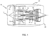
- a gas turbine engine is generally indicated at 10, having a principal and rotational axis 11.
- the engine 10 comprises, in axial flow series, an air intake 12, a propulsive fan 13, an intermediate pressure compressor 14, a high-pressure compressor 15, combustion equipment 16, a high-pressure turbine 17, an intermediate pressure turbine 18, a low-pressure turbine 19 and an exhaust nozzle 20.
- a nacelle 21 generally surrounds the engine 10 and defines both the intake 12 and the exhaust nozzle 20.
- the gas turbine engine 10 works in the conventional manner so that air entering the intake 12 is accelerated by the fan 13 to produce two air flows: a first air flow into the intermediate pressure compressor 14 and a second air flow which passes through a bypass duct 22 to provide propulsive thrust.
- the intermediate pressure compressor 14 compresses the air flow directed into it before delivering that air to the high pressure compressor 15 where further compression takes place.
- the compressed air exhausted from the high-pressure compressor 15 is directed into the combustion equipment 16 where it is mixed with fuel and the mixture combusted.
- the resultant hot combustion products then expand through, and thereby drive the high, intermediate and low-pressure turbines 17, 18, 19 before being exhausted through the nozzle 20 to provide additional propulsive thrust.
- the high 17, intermediate 18 and low 19 pressure turbines drive respectively the high pressure compressor 15, intermediate pressure compressor 14 and fan 13, each by suitable interconnecting shaft.
- the propulsive fan 13 comprises a series of hollow, wide-chord fan blades, each having an aerofoil section and a root section, the root sections securing the fan blades to a fan disc.
- the fan blades are typically formed using a diffusion bonding and super-plastic forming process.
- Three titanium layers comprising a pressure panel 30, a suction panel 31 and an interposed membrane 32 are aligned in a sandwich assembly as shown in Figure 2 and then diffusion bonded around their periphery.
- the membrane includes a gas entry slot 33 which is provided to allow gas to be forced between the pressure panel 30 and the suction panel 31 during the super-plastic forming process in order to form the cavity within the fan blade.
- the gas entry slot is subsequently sealed in the finished fan blade by welding to form a vacuum within the hollow fan blade.
- the gas entry slot 33 formed within the membrane 32 has a wider entry portion 34 (typically with a width W1 around 6.4 mm wide) extending radially within the sandwich assembly to a depth D of greater than 2 mm and typically around 40 mm. This portion is used to receive the pipe for evacuating the sealed sandwich assembly prior to diffusion bonding and subsequently the pipe for introducing gas during the super-plastic forming.
- a narrower portion 36 typically with a width W2 around 3mm.
- the narrower portion extends radially within the sandwich assembly to intersect the eventual blade tip cone 37 and then forms a meander portion 38 which is designed to prevent ingress of molten material into the cavity during subsequent sealing of the gas entry slot.
- the meander portion typically has an external radius of around 6.35 mm.
- the narrower portion 36 then resumes its radial extension to join a cupped portion 40 at the point where the edge 39 of the eventual cavity will lie.
- the sandwich assembly is subjected to pressure and heat resulting in joining of the pressure panel 30, suction panel 31 and membrane 32.
- the heat and pressure can cause the collapse of the pressure panel 30 and the suction panel 32 into the gas entry slot 33 as shown in Figure 4 . It can be seen that the collapse results in small gaps 41 that run along the edges of the gas entry slot.
- the flow of gas through the gas entry slot 33 is limited to flow through the gaps 41. This reduces the rate at which gas can be injected into the sandwich assembly. Furthermore, turbulence induced around the stepped transition 35 in the width of the gas entry slot 33 effects the gas flow rate through the gas entry slot 33.
- the control of the rate of gas introduction is important during the super-plastic forming process especially during the crack phase of the process when it is necessary to present a known volume of gas into the cavity within a fixed time period.
- a membrane for inclusion in an assembly for formation of a fan blade, the membrane having a leading edge and a trailing edge, wherein the membrane comprises a gas entry slot extending in a radial direction, the gas entry slot having a radially outer receiving portion for receiving a pipe, and a radially inner portion wherein the radially inner portion of the gas entry slot has a substantially uniform width in a direction between the leading and trailing edge of the membrane.
- the inventors have determined that the stepped increase to the cupped portion in the prior art suffers from significant collapse as the pressure panel and suction panel are less well supported in this area. Accordingly, providing a gas entry slot having a radially inner portion with a uniform width i.e. without any stepped portions, reduces turbulent flow within the gas as it travels through the gas entry slot.
- the width of the radially inner portion of the gas entry slot in the direction between the leading and trailing edges of the membrane may be less than 7 mm, e.g., less than 5 mm, e.g. less than 3 mm, e.g. less than 1.5 mm e.g. between 1.5 and 0.2 mm, such as between 1.1 and 0.8 mm or between 1.12 and 0.785 mm.
- the inventors have determined that the collapse of the gas entry slot in the membrane is greatest in the portions having the greatest width. By reducing the width to less than 1.5 mm, for example, the collapse of the gas entry slot during diffusion bonding can be further reduced.
- the thickness of the membrane is between 0.7 and 1.0 mm.
- the radially outer receiving portion may have a width (in the direction between the leading and trailing edges of the membrane) that is greater than the width of the radially inner portion e.g. it may have a width of around 6.35mm. It may have a radial depth (in a direction perpendicular to both the width and the thickness of the membrane of between 2 and 10 mm, e.g. between 2 and 3 mm.
- the radially inner portion comprises the remainder of the gas entry slot other than the radially outer receiving portion.
- the radially inner portion proximal the radially outer receiving portion comprises a radially-oriented portion which may be substantially linear.
- the radially-oriented portion of the radially inner portion of the gas entry slot intersects the eventual blade tip cone.
- the radially-oriented (e.g. linear) portion may have a length of between 40 and 70 mm, e.g. between 40 and 60 mm.
- the radially inner portion of the gas entry slot comprises a hook portion at its radially innermost end where the radially inner gas entry slot maintains its uniform width but deflects through greater than 90 degrees, e.g. equal to or greater than 100 degrees, e.g. equal to or greater than 120 degrees e.g. equal to or greater than 140 degrees e.g. equal to or greater than 160 degrees such as around 163 degrees.
- the deflection causes the slot to extend in a substantially radially inwards direction such that the inner end of the slot is inwardly spaced from the deflection (the deflection forming the innermost point of the gas entry slot).
- the hook portion defines a V- or U-shaped slot within the membrane. This replaces the cupped portion of the prior art and the associated step change in the width of the slot.
- the radially inner portion of the gas entry slot comprises a meander portion radially inwards of the hook portion i.e. interposed between the hooked portion and radially-oriented (e.g. linear) portion.
- the external radius of the meander portion may be around 6.35 mm.
- the radial spacing between the receiving portion and the radial centre of the meander portion may be between 50 and 70 mm.
- the depth of the slot (in the thickness direction) equals the thickness of the membrane such that the slot is open to both faces of the membrane.
- the membrane is formed of titanium.
- an assembly for formation of a fan blade comprising:
- the pipe may be bonded/welded into the assembly.
- the pipe may have an external diameter of 6.35mm.
- the pipe may be received to a depth matching the depth of the receiving portion e.g. to a depth of 2 mm.
- the pipe opens directly into the radially inner portion of the gas slot with the cross-sectional area of the radially inner portion matching the cross-sectional area of the pipe. This reduces turbulent flow within the gas.
- the pressure panel and suction panel are formed of titanium.
- the thickness of the slot (in the direction between the pressure panel and the suction panel) equals the thickness of the membrane such that the slot is open to both faces (i.e. the face facing the suction panel and the face facing the suction panel) of the membrane.
- the inventors have determined that the collapse of the gas entry slot in the membrane is greatest in the portions having the greatest width e.g. in the cupped portion in gas entry slot in the known assemblies.
- the width of the slot is reduced and thus the collapse of the gas entry slot during diffusion bonding can be reduced.
- the method comprises bonding the periphery of the pressure panel, suction panel and membrane e.g. by diffusion bonding, prior to inserting the pipe.
- the method comprises welding the pipe into the assembly.
- the method further comprises flowing gas into the assembly through the pipe in order to inflate the assembly.
- the method comprises evacuating the inflated assembly.
- the method comprises sealing the gas entry slot, e.g. by welding.
- the gas entry slot may be sealed at the receiving portion.
- a fan blade manufactured according to the process of the third aspect.
- the present invention provides a gas turbine engine having at least one fan blade according to the fourth aspect.
- Figures 5 and 6 show a membrane 32' having a gas entry slot 33' which extends in a radial direction. It has a radially outer receiving portion 34' and a radially inner portion having a uniform width (W) along its entire length from its outer end 42 (where it joins the receiving portion 34') to its inner end 43.
- the width (W) is the dimension in a direction extending between the leading edge 45 and the trailing edge 44
- the membrane has a thickness (T) of 0.76mm. The thickness equates to the spacing between the pressure panel 30 and the suction panel 31.
- the thickness of the slot (in the direction between the pressure panel 30 and the suction panel 31) equals the thickness of the membrane such that the slot is open to both faces (i.e. the face facing the suction panel and the face facing the suction panel) of the membrane.
- the assembly further comprises an inflation pipe 46 (shown in Figure 5 ) having an internal cross-sectional area X.
- the cross-sectional area is 0.785 mm 2 .
- the external diameter of the pipe is 6.35mm.
- the receiving portion 34' has a width of 6.35mm in order to accommodate the pipe 46.
- the receiving portion 34' has a depth of 2 mm and the pipe 46 is inserted into the receiving portion to a depth of 2 mm such that the internal diameter of the pipe 46 opens directly into the radially inner portion of the gas entry slot 33' at its outer end 42.
- the radially innermost end of the radially inner portion of the gas entry slot 33' comprises a hook portion 47 where the gas entry slot 33' maintains its uniform width but deflects through 163 degrees.
- the deflection 48 causes the slot 33' to extend in a substantially radially inwards direction such that the inner end 43 of the slot 33' is inwardly spaced from the deflection 48 (the deflection 48 forming the innermost point of the gas entry slot 33').
- the hook portion 47 is provided radially inwards of an edge 39 where the eventual cavity within the fan blade will lie.
- the gas entry slot 33' also comprises a meander portion 38' radially outwards of the hook portion 47.
- the meander portion 38' has an external radius of 6.35mm.
- the meander portion 38' is provided radially inwards of the eventual blade tip cone 37.
- the meander portion 38' is joined to the receiving portion 34' by a linear, radially-oriented portion 49 having a length of between 40 and 60 mm.
- the radial spacing between the receiving portion 34' and the radial centre of the meander portion 38' is between 50 and 70 mm.
- the pressure panel 30, membrane 32' and suction panel 31 are assembled and an evacuation pipe (typically having an outer diameter of 6.35mm and an inner diameter of 3mm) is inserted (and welded) into the gas entry slot 33' to fill the receiving portion.
- the assembly is evacuated and then subjected to diffusion bonding to join the peripheries of the panels 30, 31 and membrane 32'.
- the evacuation pipe is drilled out and replaced with inflation pipe 46 (having an outer diameter of 6.35 mm and an internal diameter of 1 mm).
- the inflation pipe is inserted to fill the receiving section and welded into place.
- the assembly is subjected to super-plastic forming where gas is flowed into the assembly through the gas entry slot 33' to inflate the assembly to form a cavity.
- the cross-sectional area of the gas entry slot 33' matches the internal cross-sectional area (X) of the inflation pipe 46.
- the inventors have determined that eliminating stepped transitions in width within the gas entry slot 33' and/or reducing the width of the gas entry slot 33' reduces the collapse of the gas entry slot 33' during diffusion bonding. In turn, this allows better control of the gas flow (and reduced turbulence) during the cracking stage of super-plastic forming such that defects and therefore rejected components can be minimised.
Landscapes
- Engineering & Computer Science (AREA)
- Mechanical Engineering (AREA)
- General Engineering & Computer Science (AREA)
- Physics & Mathematics (AREA)
- Fluid Mechanics (AREA)
- Structures Of Non-Positive Displacement Pumps (AREA)
Abstract
Description
- The present disclosure concerns a membrane, an assembly and a method for manufacturing a fan blade such as a hollow, wide-chord fan blade for a gas turbine engine.
- With reference to
Figure 1 , a gas turbine engine is generally indicated at 10, having a principal androtational axis 11. Theengine 10 comprises, in axial flow series, anair intake 12, apropulsive fan 13, anintermediate pressure compressor 14, a high-pressure compressor 15,combustion equipment 16, a high-pressure turbine 17, anintermediate pressure turbine 18, a low-pressure turbine 19 and anexhaust nozzle 20. Anacelle 21 generally surrounds theengine 10 and defines both theintake 12 and theexhaust nozzle 20. - The
gas turbine engine 10 works in the conventional manner so that air entering theintake 12 is accelerated by thefan 13 to produce two air flows: a first air flow into theintermediate pressure compressor 14 and a second air flow which passes through abypass duct 22 to provide propulsive thrust. Theintermediate pressure compressor 14 compresses the air flow directed into it before delivering that air to thehigh pressure compressor 15 where further compression takes place. - The compressed air exhausted from the high-
pressure compressor 15 is directed into thecombustion equipment 16 where it is mixed with fuel and the mixture combusted. The resultant hot combustion products then expand through, and thereby drive the high, intermediate and low-pressure turbines nozzle 20 to provide additional propulsive thrust. The high 17, intermediate 18 and low 19 pressure turbines drive respectively thehigh pressure compressor 15,intermediate pressure compressor 14 andfan 13, each by suitable interconnecting shaft. - The
propulsive fan 13 comprises a series of hollow, wide-chord fan blades, each having an aerofoil section and a root section, the root sections securing the fan blades to a fan disc. - The fan blades are typically formed using a diffusion bonding and super-plastic forming process. Three titanium layers comprising a
pressure panel 30, asuction panel 31 and an interposedmembrane 32 are aligned in a sandwich assembly as shown inFigure 2 and then diffusion bonded around their periphery. - The membrane includes a
gas entry slot 33 which is provided to allow gas to be forced between thepressure panel 30 and thesuction panel 31 during the super-plastic forming process in order to form the cavity within the fan blade. The gas entry slot is subsequently sealed in the finished fan blade by welding to form a vacuum within the hollow fan blade. - As shown in
Figure 3 , thegas entry slot 33 formed within themembrane 32 has a wider entry portion 34 (typically with a width W1 around 6.4 mm wide) extending radially within the sandwich assembly to a depth D of greater than 2 mm and typically around 40 mm. This portion is used to receive the pipe for evacuating the sealed sandwich assembly prior to diffusion bonding and subsequently the pipe for introducing gas during the super-plastic forming. - There is then a
stepped transition 35 to a narrower portion 36 (typically with a width W2 around 3mm). The narrower portion extends radially within the sandwich assembly to intersect the eventualblade tip cone 37 and then forms ameander portion 38 which is designed to prevent ingress of molten material into the cavity during subsequent sealing of the gas entry slot. The meander portion typically has an external radius of around 6.35 mm. Thenarrower portion 36 then resumes its radial extension to join a cuppedportion 40 at the point where theedge 39 of the eventual cavity will lie. - During the diffusion bonding process, the sandwich assembly is subjected to pressure and heat resulting in joining of the
pressure panel 30,suction panel 31 andmembrane 32. The heat and pressure can cause the collapse of thepressure panel 30 and thesuction panel 32 into thegas entry slot 33 as shown inFigure 4 . It can be seen that the collapse results insmall gaps 41 that run along the edges of the gas entry slot. - During inflation of the cavity within the fan blade in the super-plastic forming process, the flow of gas through the
gas entry slot 33 is limited to flow through thegaps 41. This reduces the rate at which gas can be injected into the sandwich assembly. Furthermore, turbulence induced around thestepped transition 35 in the width of thegas entry slot 33 effects the gas flow rate through thegas entry slot 33. - The control of the rate of gas introduction is important during the super-plastic forming process especially during the crack phase of the process when it is necessary to present a known volume of gas into the cavity within a fixed time period.
- There is the need for a membrane, an assembly and method for manufacturing a fan blade which mitigates at least some of the problems associated with the prior art.
- In a first aspect, there is provided a membrane for inclusion in an assembly for formation of a fan blade, the membrane having a leading edge and a trailing edge,
wherein the membrane comprises a gas entry slot extending in a radial direction, the gas entry slot having a radially outer receiving portion for receiving a pipe, and a radially inner portion wherein the radially inner portion of the gas entry slot has a substantially uniform width in a direction between the leading and trailing edge of the membrane. - The inventors have determined that the stepped increase to the cupped portion in the prior art suffers from significant collapse as the pressure panel and suction panel are less well supported in this area. Accordingly, providing a gas entry slot having a radially inner portion with a uniform width i.e. without any stepped portions, reduces turbulent flow within the gas as it travels through the gas entry slot.
- Furthermore, the collapse of the gas entry slot during diffusion bonding can be reduced.
- Optional features will now be set out. These are applicable singly or in any combination with any aspect.
- The width of the radially inner portion of the gas entry slot in the direction between the leading and trailing edges of the membrane may be less than 7 mm, e.g., less than 5 mm, e.g. less than 3 mm, e.g. less than 1.5 mm e.g. between 1.5 and 0.2 mm, such as between 1.1 and 0.8 mm or between 1.12 and 0.785 mm.
- The inventors have determined that the collapse of the gas entry slot in the membrane is greatest in the portions having the greatest width. By reducing the width to less than 1.5 mm, for example, the collapse of the gas entry slot during diffusion bonding can be further reduced.
- In some embodiments, the width (W) of the radially inner portion of the gas entry slot in the direction between the leading and trailing edges is defined by the following equation:

- In some embodiments, the thickness of the membrane is between 0.7 and 1.0 mm.
- The radially outer receiving portion may have a width (in the direction between the leading and trailing edges of the membrane) that is greater than the width of the radially inner portion e.g. it may have a width of around 6.35mm. It may have a radial depth (in a direction perpendicular to both the width and the thickness of the membrane of between 2 and 10 mm, e.g. between 2 and 3 mm.
- There is a stepped transition from the radially outer receiving portion to the radially inner portion i.e. the radially inner portion comprises the remainder of the gas entry slot other than the radially outer receiving portion.
- In some embodiments, the radially inner portion proximal the radially outer receiving portion comprises a radially-oriented portion which may be substantially linear. The radially-oriented portion of the radially inner portion of the gas entry slot intersects the eventual blade tip cone. The radially-oriented (e.g. linear) portion may have a length of between 40 and 70 mm, e.g. between 40 and 60 mm.
- In some embodiments, the radially inner portion of the gas entry slot comprises a hook portion at its radially innermost end where the radially inner gas entry slot maintains its uniform width but deflects through greater than 90 degrees, e.g. equal to or greater than 100 degrees, e.g. equal to or greater than 120 degrees e.g. equal to or greater than 140 degrees e.g. equal to or greater than 160 degrees such as around 163 degrees. The deflection causes the slot to extend in a substantially radially inwards direction such that the inner end of the slot is inwardly spaced from the deflection (the deflection forming the innermost point of the gas entry slot).
- Accordingly, the hook portion defines a V- or U-shaped slot within the membrane. This replaces the cupped portion of the prior art and the associated step change in the width of the slot.
- In some embodiments, the radially inner portion of the gas entry slot comprises a meander portion radially inwards of the hook portion i.e. interposed between the hooked portion and radially-oriented (e.g. linear) portion. The external radius of the meander portion may be around 6.35 mm.
- The radial spacing between the receiving portion and the radial centre of the meander portion may be between 50 and 70 mm.
- In some embodiments, the depth of the slot (in the thickness direction) equals the thickness of the membrane such that the slot is open to both faces of the membrane.
- In some embodiments, the membrane is formed of titanium.
- In a second aspect, there is provided an assembly for formation of a fan blade, the assembly comprising:
- a suction panel;
- a pressure panel; and
- a membrane according to the first aspect, the membrane being sandwiched between the suction panel and pressure panel.
- In some embodiments, the assembly further comprises a pipe having an internal cross-sectional area X for insertion into the receiving portion of the gas entry slot and the width (W) of the radially inner portion of the gas entry slot in the direction between the leading and trailing edges is defined by the following equation:

- The pipe may be bonded/welded into the assembly.
- The pipe may have an external diameter of 6.35mm.
- The pipe may be received to a depth matching the depth of the receiving portion e.g. to a depth of 2 mm. In this way, the pipe opens directly into the radially inner portion of the gas slot with the cross-sectional area of the radially inner portion matching the cross-sectional area of the pipe. This reduces turbulent flow within the gas.
- In some embodiments, the pressure panel and suction panel are formed of titanium.
- In some embodiments, the thickness of the slot (in the direction between the pressure panel and the suction panel) equals the thickness of the membrane such that the slot is open to both faces (i.e. the face facing the suction panel and the face facing the suction panel) of the membrane.
- In a third aspect, the present invention provides a method of forming a fan blade comprising providing an assembly according to the second aspect wherein the membrane has a thickness (T), inserting a pipe having an internal cross-sectional area (X) into the gas entry slot in the membrane,
wherein the radially inner portion of the gas entry slot has a width (W) in a direction between the leading and trailing edge of the membrane such that:
- The inventors have determined that the collapse of the gas entry slot in the membrane is greatest in the portions having the greatest width e.g. in the cupped portion in gas entry slot in the known assemblies. By using a membrane having a gas entry slot with a radially inner portion having a cross-sectional area (W x T) which matches the cross-sectional area of the pipe, the width of the slot is reduced and thus the collapse of the gas entry slot during diffusion bonding can be reduced.
- If the pipe is inserted into the receiving portion to a depth matching the depth of the receiving portion, turbulence in the gas flow can also be reduced.
- In some embodiments, the method comprises bonding the periphery of the pressure panel, suction panel and membrane e.g. by diffusion bonding, prior to inserting the pipe.
- In some embodiments, the method comprises welding the pipe into the assembly.
- In some embodiments, the method further comprises flowing gas into the assembly through the pipe in order to inflate the assembly.
- In some embodiments, the method comprises evacuating the inflated assembly.
- In some embodiments, the method comprises sealing the gas entry slot, e.g. by welding. The gas entry slot may be sealed at the receiving portion.
- In a fourth aspect, there is provided a fan blade manufactured according to the process of the third aspect.
- In a fifth aspect, the present invention provides a gas turbine engine having at least one fan blade according to the fourth aspect.
- The skilled person will appreciate that except where mutually exclusive, a feature described in relation to any one of the above aspects may be applied mutatis mutandis to any other aspect. Furthermore except where mutually exclusive any feature described herein may be applied to any aspect and/or combined with any other feature described herein.
- Embodiments will now be described by way of example only with reference to the accompanying drawings in which:
-
Figure 1 shows an axial cross-section through a gas turbine engine; -
Figure 2 shows a known assembly for manufacture of a fan blade; -
Figure 3 shows the geometry of the gas entry slot in the known assembly; -
Figure 4 shows the collapse of the gas entry slot after diffusion bonding in the known assembly; and -
Figures 5 and6 show a gas entry slot in a membrane for inclusion in an assembly for forming a fan blade. -
Figures 5 and6 show a membrane 32' having a gas entry slot 33' which extends in a radial direction. It has a radially outer receiving portion 34' and a radially inner portion having a uniform width (W) along its entire length from its outer end 42 (where it joins the receiving portion 34') to itsinner end 43. The width (W) is the dimension in a direction extending between theleading edge 45 and the trailingedge 44 - The membrane has a thickness (T) of 0.76mm. The thickness equates to the spacing between the
pressure panel 30 and thesuction panel 31. - The thickness of the slot (in the direction between the
pressure panel 30 and the suction panel 31) equals the thickness of the membrane such that the slot is open to both faces (i.e. the face facing the suction panel and the face facing the suction panel) of the membrane. - The assembly further comprises an inflation pipe 46 (shown in
Figure 5 ) having an internal cross-sectional area X. For example, where the pipe has an internal diameter of 1 mm, the cross-sectional area is 0.785 mm2. The external diameter of the pipe is 6.35mm. The receiving portion 34' has a width of 6.35mm in order to accommodate thepipe 46. - The width (W) of the radially inner portion of the gas entry slot 33' in the direction between the leading and trailing
edges 
- Accordingly, where the pipe has an internal diameter of 1 mm, the width (W) of the gas entry slot 33' in the direction between the leading and trailing
edges 
- This results in the cross-sectional area of the
pipe 46 matching the cross-sectional area of the radially inner portion of the gas entry slot 33'. - The receiving portion 34' has a depth of 2 mm and the
pipe 46 is inserted into the receiving portion to a depth of 2 mm such that the internal diameter of thepipe 46 opens directly into the radially inner portion of the gas entry slot 33' at itsouter end 42. - The radially innermost end of the radially inner portion of the gas entry slot 33' comprises a
hook portion 47 where the gas entry slot 33' maintains its uniform width but deflects through 163 degrees. Thedeflection 48 causes the slot 33' to extend in a substantially radially inwards direction such that theinner end 43 of the slot 33' is inwardly spaced from the deflection 48 (thedeflection 48 forming the innermost point of the gas entry slot 33'). - The
hook portion 47 is provided radially inwards of anedge 39 where the eventual cavity within the fan blade will lie. - The gas entry slot 33' also comprises a meander portion 38' radially outwards of the
hook portion 47. The meander portion 38' has an external radius of 6.35mm. - The meander portion 38' is provided radially inwards of the eventual
blade tip cone 37. - The meander portion 38' is joined to the receiving portion 34' by a linear, radially-oriented
portion 49 having a length of between 40 and 60 mm. The radial spacing between the receiving portion 34' and the radial centre of the meander portion 38' is between 50 and 70 mm. - To manufacture a fan blade, the
pressure panel 30, membrane 32' andsuction panel 31 are assembled and an evacuation pipe (typically having an outer diameter of 6.35mm and an inner diameter of 3mm) is inserted (and welded) into the gas entry slot 33' to fill the receiving portion. The assembly is evacuated and then subjected to diffusion bonding to join the peripheries of thepanels - Next, the evacuation pipe is drilled out and replaced with inflation pipe 46 (having an outer diameter of 6.35 mm and an internal diameter of 1 mm). The inflation pipe is inserted to fill the receiving section and welded into place. The assembly is subjected to super-plastic forming where gas is flowed into the assembly through the gas entry slot 33' to inflate the assembly to form a cavity. The cross-sectional area of the gas entry slot 33' matches the internal cross-sectional area (X) of the
inflation pipe 46. - The inventors have determined that eliminating stepped transitions in width within the gas entry slot 33' and/or reducing the width of the gas entry slot 33' reduces the collapse of the gas entry slot 33' during diffusion bonding. In turn, this allows better control of the gas flow (and reduced turbulence) during the cracking stage of super-plastic forming such that defects and therefore rejected components can be minimised.
- It will be understood that the invention is not limited to the embodiments above-described and various modifications and improvements can be made without departing from the concepts described herein. Except where mutually exclusive, any of the features may be employed separately or in combination with any other features and the disclosure extends to and includes all combinations and sub-combinations of one or more features described herein.
Claims (15)
- A membrane for inclusion in an assembly for formation of a fan blade, the membrane having a leading edge and a trailing edge,
wherein the membrane comprises a gas entry slot extending in a radial direction, the gas entry slot having a radially outer receiving portion for receiving a pipe, and a radially inner portion wherein the radially inner portion of the gas entry slot has a substantially uniform width in a direction between the leading and trailing edge of the membrane. - A membrane according to claim 1 wherein the width of the radially inner portion of the gas entry slot in the direction between the leading and trailing edges of the membrane is less than 3mm and optionally between 1.1 and 0.8 mm.
- A membrane according to any one of the preceding claims wherein the width (W) of the gas entry slot in the direction between the leading and trailing edges is defined:

- A membrane according to any one of the preceding claims wherein the radially inner portion of the gas entry slot comprises a hook portion where the gas entry slot deflects through greater than 90 degrees and optionally wherein the gas entry slot deflects through substantially 135 degrees.
- A membrane to any one of the preceding claims wherein the gas entry slot comprises a meander portion radially outwards of the hook portion.
- An assembly for formation of a fan blade, the assembly comprising:a suction panel;a pressure panel; anda membrane according to any one of claims 1 to 5, the membrane being sandwiched between the suction panel and pressure panel.
- An assembly according to claim 6 further comprising a pipe having an internal cross-sectional area X for insertion into the gas entry slot and wherein the width (W) of the gas entry slot in the direction between the leading and trailing edges is defined by:

- An assembly according to claim 7 wherein the pipe is inserted into the receiving portion to a depth matching the depth of the receiving portion such that the pipe abuts the radially inner portion of the gas entry slot.
- A method of forming a fan blade comprising providing an assembly according to claim 7 or 8 wherein the membrane has a thickness (T) and inserting a pipe having an internal cross-sectional area (X) into the gas entry slot in the membrane,
wherein the gas entry slot has a width (W) in a direction between the leading and trailing edge of the membrane such that:
- A method according to claim 9 comprising bonding the periphery of the pressure panel, suction panel and membrane prior to inserting the pipe.
- A method according to claim 9 or 10 comprising inserting the pipe into the receiving portion to a depth matching the depth of the receiving portion such that the pipe abuts the radially inner portion of the gas entry slot.
- A method according to any one of claims 9 to 11 further comprising flowing gas into the assembly through the pipe in order to inflate the assembly.
- A method according to any one of claims 9 to 12 wherein the method further comprises sealing the gas entry slot.
- A fan blade manufactured according to the method of any one of claims 9 to 13.
- A gas turbine engine having at least one fan blade according to claim 14.
Applications Claiming Priority (1)
| Application Number | Priority Date | Filing Date | Title |
|---|---|---|---|
| GBGB1710651.9A GB201710651D0 (en) | 2017-07-03 | 2017-07-03 | Manufacturing assembly and method |
Publications (1)
| Publication Number | Publication Date |
|---|---|
| EP3424608A1 true EP3424608A1 (en) | 2019-01-09 |
Family
ID=59592415
Family Applications (1)
| Application Number | Title | Priority Date | Filing Date |
|---|---|---|---|
| EP18178402.6A Withdrawn EP3424608A1 (en) | 2017-07-03 | 2018-06-19 | Manufacturing assembly and method |
Country Status (3)
| Country | Link |
|---|---|
| US (1) | US10639751B2 (en) |
| EP (1) | EP3424608A1 (en) |
| GB (1) | GB201710651D0 (en) |
Citations (3)
| Publication number | Priority date | Publication date | Assignee | Title |
|---|---|---|---|---|
| EP0549172A1 (en) * | 1991-12-09 | 1993-06-30 | General Electric Company | Design and processing method for manufacturing hollow airfoils (three-piece concept) |
| EP2469027A2 (en) * | 2010-12-23 | 2012-06-27 | Rolls-Royce plc | A diffusion bonded and superplastically formed turbomachine blade |
| EP2862643A1 (en) * | 2013-10-21 | 2015-04-22 | Rolls-Royce plc | Hollow component manufacture |
Family Cites Families (18)
| Publication number | Priority date | Publication date | Assignee | Title |
|---|---|---|---|---|
| GB9122874D0 (en) * | 1991-10-29 | 1991-12-11 | Rolls Royce Plc | A method of manufacturing an article,a method of diffusion bonding and a vacuum chamber |
| US5479705A (en) * | 1992-05-01 | 1996-01-02 | Rolls-Royce Plc | Method of manufacturing an article by superplastic forming and diffusion bonding |
| GB9209464D0 (en) * | 1992-05-01 | 1992-06-17 | Rolls Royce Plc | A method of manufacturing an article by superplastic forming and diffusion bonding |
| GB2269555B (en) * | 1992-08-14 | 1995-01-04 | Rolls Royce Plc | A method of manufacturing an article by superplastic forming and diffusion bonding |
| GB2269556B (en) * | 1992-08-15 | 1994-09-28 | Rolls Royce Plc | A method of manufacturing an article by diffusion bonding |
| GB2289429B (en) * | 1994-05-10 | 1997-01-22 | Rolls Royce Plc | Hollow component manufacture |
| GB9721338D0 (en) * | 1997-10-09 | 1997-12-10 | Rolls Royce Plc | A method of manufacturing an article by diffusion bonding |
| GB9924219D0 (en) * | 1999-10-14 | 1999-12-15 | Rolls Royce Plc | A method of manufacturing an article by superplastic forming and diffusion bonding |
| GB2360236B (en) * | 2000-03-18 | 2003-05-14 | Rolls Royce Plc | A method of manufacturing an article by diffusion bonding and superplastic forming |
| GB0022531D0 (en) * | 2000-09-14 | 2000-11-01 | Rolls Royce Plc | A method of manufacturing an article by diffusion bonding |
| GB0203955D0 (en) * | 2002-02-20 | 2002-04-03 | Rolls Royce Plc | A method of manufacturing an article by diffusion bonding and super[lastic forming |
| GB2397855B (en) * | 2003-01-30 | 2006-04-05 | Rolls Royce Plc | A turbomachine aerofoil |
| GB0318937D0 (en) * | 2003-08-13 | 2003-09-17 | Rolls Royce Plc | A method of manufacturing an article by diffusion bonding and superplastic forming |
| GB0903281D0 (en) * | 2009-02-27 | 2009-04-08 | Rolls Royce Plc | Method of manufacturing a blade |
| GB0903280D0 (en) * | 2009-02-27 | 2009-04-08 | Rolls Royce Plc | Method of manufacturing a blade |
| GB0911416D0 (en) * | 2009-07-02 | 2009-08-12 | Rolls Royce Plc | A method of forming an internal structure within a hollow component |
| FR2950551B1 (en) * | 2009-09-25 | 2011-10-28 | Commissariat Energie Atomique | METHOD FOR MANUFACTURING HOT ISOSTATIC COMPRESSION HOLLOW ZONE MODULE |
| GB2481000B (en) * | 2010-06-03 | 2012-08-08 | Rolls Royce Plc | A method of manufacturing an article by diffusion bonding and superplastic forming |
-
2017
- 2017-07-03 GB GBGB1710651.9A patent/GB201710651D0/en not_active Ceased
-
2018
- 2018-06-19 EP EP18178402.6A patent/EP3424608A1/en not_active Withdrawn
- 2018-06-25 US US16/016,735 patent/US10639751B2/en active Active
Patent Citations (3)
| Publication number | Priority date | Publication date | Assignee | Title |
|---|---|---|---|---|
| EP0549172A1 (en) * | 1991-12-09 | 1993-06-30 | General Electric Company | Design and processing method for manufacturing hollow airfoils (three-piece concept) |
| EP2469027A2 (en) * | 2010-12-23 | 2012-06-27 | Rolls-Royce plc | A diffusion bonded and superplastically formed turbomachine blade |
| EP2862643A1 (en) * | 2013-10-21 | 2015-04-22 | Rolls-Royce plc | Hollow component manufacture |
Also Published As
| Publication number | Publication date |
|---|---|
| US20190001449A1 (en) | 2019-01-03 |
| GB201710651D0 (en) | 2017-08-16 |
| US10639751B2 (en) | 2020-05-05 |
Similar Documents
| Publication | Publication Date | Title |
|---|---|---|
| US10808543B2 (en) | Rotors with modulus mistuned airfoils | |
| US10815798B2 (en) | Turbine engine blade with leading edge strip | |
| CN108368855B (en) | Closed impeller made from additive manufacturing with cavities in hub and shroud | |
| CA2705631C (en) | Method for manufacturing vanes integrated into a ring and rectifier obtained by the method | |
| US20130017067A1 (en) | Method of beam welding of an impeller with performance of two passes on a slot ; impeller and turbo machine having such weld configuration | |
| US20120027603A1 (en) | Dual blisks in the high-pressure compressor | |
| EP3424608A1 (en) | Manufacturing assembly and method | |
| US10689990B2 (en) | Vane arrangement for a gas turbine engine | |
| US20160265365A1 (en) | Manufacture of a hollow aerofoil | |
| EP2578910A1 (en) | Strip seals | |
| EP3085893A1 (en) | Mistuned gas turbine engine rotor | |
| EP3091189A1 (en) | Airfoil assembly for a stator of a gas turbine engine compressor | |
| US7857584B2 (en) | Stator vane with localized reworking of shape, stator section, compression stage, compressor and turbomachine comprising such a vane | |
| US10480528B2 (en) | Superplastic forming | |
| US11060410B2 (en) | Method of forming a protective sheath for an aerofoil component | |
| US9920642B2 (en) | Compressor airfoil | |
| EP1819904B1 (en) | Blade for a flow machine | |
| US11684997B2 (en) | Manufacture of a hollow aerofoil | |
| US12607201B2 (en) | Impeller containment system | |
| US20180038386A1 (en) | Fan blade with composite cover | |
| US10001134B2 (en) | Rotor disc | |
| US20110081238A1 (en) | Gas turbine engine sheet metal vane | |
| US20150306713A1 (en) | A method of fabricating a rotor of a turbofan engine | |
| GB2530553A (en) | Fan blade and method of manufacture |
Legal Events
| Date | Code | Title | Description |
|---|---|---|---|
| PUAI | Public reference made under article 153(3) epc to a published international application that has entered the european phase |
Free format text: ORIGINAL CODE: 0009012 |
|
| STAA | Information on the status of an ep patent application or granted ep patent |
Free format text: STATUS: THE APPLICATION HAS BEEN PUBLISHED |
|
| AK | Designated contracting states |
Kind code of ref document: A1 Designated state(s): AL AT BE BG CH CY CZ DE DK EE ES FI FR GB GR HR HU IE IS IT LI LT LU LV MC MK MT NL NO PL PT RO RS SE SI SK SM TR |
|
| AX | Request for extension of the european patent |
Extension state: BA ME |
|
| STAA | Information on the status of an ep patent application or granted ep patent |
Free format text: STATUS: REQUEST FOR EXAMINATION WAS MADE |
|
| 17P | Request for examination filed |
Effective date: 20190621 |
|
| RBV | Designated contracting states (corrected) |
Designated state(s): AL AT BE BG CH CY CZ DE DK EE ES FI FR GB GR HR HU IE IS IT LI LT LU LV MC MK MT NL NO PL PT RO RS SE SI SK SM TR |
|
| RAP1 | Party data changed (applicant data changed or rights of an application transferred) |
Owner name: ROLLS-ROYCE PLC |
|
| STAA | Information on the status of an ep patent application or granted ep patent |
Free format text: STATUS: THE APPLICATION HAS BEEN WITHDRAWN |
|
| 18W | Application withdrawn |
Effective date: 20200605 |