EP3424551A1 - Guide wire - Google Patents
Guide wire Download PDFInfo
- Publication number
- EP3424551A1 EP3424551A1 EP16892679.8A EP16892679A EP3424551A1 EP 3424551 A1 EP3424551 A1 EP 3424551A1 EP 16892679 A EP16892679 A EP 16892679A EP 3424551 A1 EP3424551 A1 EP 3424551A1
- Authority
- EP
- European Patent Office
- Prior art keywords
- wire
- coil
- main body
- guide wire
- support portion
- Prior art date
- Legal status (The legal status is an assumption and is not a legal conclusion. Google has not performed a legal analysis and makes no representation as to the accuracy of the status listed.)
- Granted
Links
Images



Classifications
-
- A—HUMAN NECESSITIES
- A61—MEDICAL OR VETERINARY SCIENCE; HYGIENE
- A61M—DEVICES FOR INTRODUCING MEDIA INTO, OR ONTO, THE BODY; DEVICES FOR TRANSDUCING BODY MEDIA OR FOR TAKING MEDIA FROM THE BODY; DEVICES FOR PRODUCING OR ENDING SLEEP OR STUPOR
- A61M25/00—Catheters; Hollow probes
- A61M25/01—Introducing, guiding, advancing, emplacing or holding catheters
- A61M25/09—Guide wires
-
- A—HUMAN NECESSITIES
- A61—MEDICAL OR VETERINARY SCIENCE; HYGIENE
- A61M—DEVICES FOR INTRODUCING MEDIA INTO, OR ONTO, THE BODY; DEVICES FOR TRANSDUCING BODY MEDIA OR FOR TAKING MEDIA FROM THE BODY; DEVICES FOR PRODUCING OR ENDING SLEEP OR STUPOR
- A61M25/00—Catheters; Hollow probes
- A61M25/01—Introducing, guiding, advancing, emplacing or holding catheters
- A61M25/09—Guide wires
- A61M2025/09058—Basic structures of guide wires
- A61M2025/09083—Basic structures of guide wires having a coil around a core
-
- A—HUMAN NECESSITIES
- A61—MEDICAL OR VETERINARY SCIENCE; HYGIENE
- A61M—DEVICES FOR INTRODUCING MEDIA INTO, OR ONTO, THE BODY; DEVICES FOR TRANSDUCING BODY MEDIA OR FOR TAKING MEDIA FROM THE BODY; DEVICES FOR PRODUCING OR ENDING SLEEP OR STUPOR
- A61M25/00—Catheters; Hollow probes
- A61M25/01—Introducing, guiding, advancing, emplacing or holding catheters
- A61M25/09—Guide wires
- A61M2025/09058—Basic structures of guide wires
- A61M2025/09083—Basic structures of guide wires having a coil around a core
- A61M2025/09091—Basic structures of guide wires having a coil around a core where a sheath surrounds the coil at the distal part
-
- A—HUMAN NECESSITIES
- A61—MEDICAL OR VETERINARY SCIENCE; HYGIENE
- A61M—DEVICES FOR INTRODUCING MEDIA INTO, OR ONTO, THE BODY; DEVICES FOR TRANSDUCING BODY MEDIA OR FOR TAKING MEDIA FROM THE BODY; DEVICES FOR PRODUCING OR ENDING SLEEP OR STUPOR
- A61M25/00—Catheters; Hollow probes
- A61M25/01—Introducing, guiding, advancing, emplacing or holding catheters
- A61M25/09—Guide wires
- A61M2025/09175—Guide wires having specific characteristics at the distal tip
Definitions
- the present invention relates to a guide wire.
- a guide wire is used in order to a catheter used for treatment of a site having difficulties in surgery, minimally invasive treatment for a human body, or examination such as cardioangiography.
- PCI percutaneous coronary intervention
- the guide wire together with the balloon catheter is inserted into the vicinity of a stenosed site of a coronary artery which serves as a target site, and the distal portion of the balloon catheter is guided to the vicinity of the vascular stenosed site.
- a guide wire disclosed in PTL 1 is known as the guide wire used for this treatment.
- This guide wire has a flexible wire main body (core wire), a primary coil fixed to a distal portion of the wire main body, and a secondary coil disposed on a proximal side of the primary coil and installed so as to cover an outer periphery of the wire main body.
- This secondary coil is disposed so as not be fixed to the wire main body and the primary coil. Therefore, the secondary coil can be rotated independently of the wire main body and the primary coil. Accordingly, for example, even if the secondary coil is caught by the vascular stenosed site, the wire main body and the distal coil can be rotationally operated.
- the wire main body and the secondary coil are separated from each other, and a gap is formed therebetween. Therefore, in some cases, axial misalignment occurs between the wire main body and the secondary coil. That is, in some cases, the wire main body and the secondary coil are unintentionally misaligned from each other in a radial direction. Depending on a degree of this misalignment, there is a possibility that operability may become poor.
- An object of the present invention is to provide a guide wire capable of achieving excellent operability inside a steeply curved blood vessel or inside a vascular stenosed site.
- the tubular portion is configured to be rotatable with respect to the wire main body. Therefore, even if the tubular portion is caught by a stenosed site, the wire main body can be rotationally operated.
- the guide wire has the support portion that supports the tubular portion. Therefore, it is possible to prevent axial misalignment between the tubular portion and the wire main body. That is, it is possible to restrict a positional relationship between the tubular portion and the wire main body. As a result, it is possible to prevent the tubular portion and the wire main body from being unintentionally misaligned from each other in a radial direction. According to the above-described configurations, the guide wire according to the present invention is excellent in operability.
- Fig. 1 is a longitudinal cross-sectional view (schematic side view) illustrating a first embodiment of a guide wire according to the present invention.
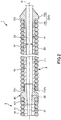
- Fig. 2 is an enlarged cross-sectional view of a tubular portion and a support portion, which are illustrated in Fig. 1 .
- a right side in a long axis direction in Figs. 1 and 2 will be referred to as a "proximal end”
- a left side will be referred to as a “distal end”
- an upper side will be referred to as "upward”
- a lower side will be referred to as "downward”.
- Figs. 1 is a longitudinal cross-sectional view (schematic side view) illustrating a first embodiment of a guide wire according to the present invention.
- Fig. 2 is an enlarged cross-sectional view of a tubular portion and a support portion, which are illustrated in Fig. 1 .
- proximal end a right side in a long axis
- the guide wire according to the present invention achieves excellent operability in, for example, a vascular stenosed site having a decreased distance between tube walls of a blood vessel, or a site having a steeply curved blood vessel.
- a case where the guide wire according to the present invention is located inside the vascular stenosed site will be described as a representative example.
- a guide wire 1 illustrated in Fig. 1 is a catheter guide wire used by being inserted into a lumen of a catheter (including an endoscope), and includes a first wire 2 located on a distal side, a flexible wire main body 11 formed by joining (connecting) a second wire 3 located on a proximal side of the first wire 2 to the first wire 2, a distal member 4 having a coil 41 fixed to a distal portion of the wire main body 11 by using fixing members 42 and 43, a coil 5 (tubular member) disposed on a proximal side of the coil 41, on an outer periphery of the wire main body 11, and a support portion 7.
- a total length of the guide wire 1 is not particularly limited. However, it is preferable that the total length is approximately 200 to 5,000 mm.
- an outer diameter of the guide wire 1 is not particularly limited. However, it is generally preferable that the outer diameter is approximately 0.2 to 1.2 mm.
- the first wire 2 is configured to include a flexible or elastic wire rod (core material) .
- a length of the first wire 2 is not particularly limited. However, it is preferable that the length is approximately 20 to 1,000 mm.
- the first wire 2 has a portion whose outer diameter is constant (constant outer diameter portion), and a portion having a tapered shape whose outer diameter gradually decreases in a distal direction (gradually decreasing outer diameter portion) (tapered portion).
- the first wire 2 sequentially from the proximal side to the distal side, the first wire 2 has a constant outer diameter portion 25, a tapered portion (proximal side tapered portion) 24, a constant outer diameter portion 23 having the outer diameter smaller than that of the constant outer diameter portion 25, a tapered portion (distal side tapered portion) 22, and a most distal portion 21.
- the first wire 2 has the tapered portions 22 and 24. Accordingly, rigidity (flexural rigidity or torsional rigidity) of the first wire 2 can be gradually reduced in the distal direction. As a result, the guide wire 1 is allowed to have satisfactory flexibility in the distal portion. Accordingly, followability to a body lumen (body-cavity) of the blood vessel and safety can be improved. Therefore, it is possible to prevent the guide wire 1 from being bent.
- Each tapered angle of the tapered portions 22 and 24 (reduction rate of the outer diameter) is constant along a longitudinal direction of the wire main body 11 (hereinafter, simply referred to as a "longitudinal direction"). However, there may be a portion changing along the longitudinal direction.
- the wire main body 11 may be formed so that a location having the relatively large tapered angle (reduction rate of the outer diameter) and a location having the relatively small tapered angle are alternately repeated multiple times.
- the most distal portion 21 can be a constant outer diameter portion whose outer diameter is smaller than that of the constant outer diameter portion 23.
- the most distal portion 21 may have a flat plate shape (ribbon shape), and may be configured to be deformable (reshaping: shaping available) into a desired shape.
- a physician uses the guide wire by bending the distal portion of the guide wire in advance into a desired shape in some cases. Bending the distal portion of the guide wire into the desired shape in this way is called reshaping. Then, since the most distal portion 21 is provided, the reshaping can be easily and reliably performed. Accordingly, operability is remarkably improved when the guide wire 1 is inserted into a living body.
- the length of the most distal portion 21 is not particularly limited. However, it is preferable that the length is approximately 5 to 200 mm, and more preferably approximately 10 to 150 mm.
- a configuration material (material) of the first wire 2 is not particularly limited.
- various metal materials such as a Ni-Ti alloy and stainless steel can be used.
- a pseudo-elastic alloy including a super-elastic alloy.
- the super-elastic alloy is comparatively flexible, has resilience, and is less likely to be bent.
- the first wire 2 is configured to include the super-elastic alloy. In this manner, the guide wire 1 is formed so that a distal side portion is allowed to obtain sufficient flexibility and the resilience against bending. Accordingly, followability to a complicatedly curved and bent blood vessel is improved, and more excellent operability can be obtained.
- the distal end of the second wire 3 is joined (connected) to the proximal end (proximal end of the constant outer diameter portion 25) of the first wire 2.
- the second wire 3 is configured to include a highly rigid wire rod (core material) .
- the length of the second wire 3 is not particularly limited. However, it is preferable that the length is approximately 20 to 4,800 mm, and more preferably approximately 1,400 to 3,000 mm.
- a method of joining the first wire 2 and the second wire 3 to each other is not particularly limited. For example, various methods welding and brazing can be used. However, it is preferable that the first wire 2 and the second wire 3 are joined by using the welding.
- the second wire 3 is configured to include a material different from that of the first wire 2.
- the second wire 3 is configured to include a material having an elastic modulus (Young's modulus (longitudinal elastic modulus), a modulus of rigidity (modulus of transverse elasticity), and a bulk modulus) which is higher than the configuration material of the first wire 2.
- an elastic modulus Young's modulus (longitudinal elastic modulus), a modulus of rigidity (modulus of transverse elasticity), and a bulk modulus
- rigidity flexural rigidity or torsional rigidity
- the guide wire 1 is allowed to have a so-called strong body. Accordingly, pushing performance and torque transmission performance are improved, thereby achieving more excellent operability.
- a configuration material (material) of the second wire 3 is not particularly limited as long as the configuration material of the second wire 3 is different from that of the first wire 2. It is possible to use various metal materials such as stainless steel (for example, all SUS types such as SUS 304, SUS 303, SUS 316, SUS 316L, SUS316J1, SUS 316J1L, SUS 405, SUS 430, SUS 434, SUS 444, SUS 429, SUS 430F, and SUS302), a piano wire, a cobalt alloy, and a pseudo-elastic alloy. However, it is preferable to use the stainless steel or the cobalt alloy, and is more preferable to use the stainless steel. Since the second wire 3 is configured to include the stainless steel or the cobalt alloy, the guide wire 1 can obtain the more excellent pushing performance and torque transmission performance.
- stainless steel for example, all SUS types such as SUS 304, SUS 303, SUS 316, SUS 316L, SUS316J1, SUS
- the wire main body 11 is formed by joining the first wire 2 and the second wire 3 to each other.
- the wire main body 11 may be configured to include one continuous wire rod.
- the coil 41 whose outer diameter and inner diameter are constant is installed in a distal portion outer periphery of the wire main body 11, that is, the most distal portion 21 of the first wire 2 and the outer periphery of the distal portion of the tapered portion 22.
- the coil 41 is a member formed by winding a wire rod 40 in a spiral shape, and is installed so as to cover the distal portion of the wire main body 11, that is, the most distal portion 21 of the first wire 2, and a portion except for the proximal portion of the tapered portion 22.
- the first wire 2 is inserted into a substantially central portion inside the coil 41 in a non-contact manner.
- the length (length of the wire main body 11 in the longitudinal direction) of the coil 41 is preferably 5 to 500 mm, and more preferably 10 to 300 mm.
- the inner diameter (inner diameter of the wire main body 11 in a circumferential direction) of the coil 41 is preferably 0.1 to 0.95 mm, and more preferably 0.2 to 0.7 mm.
- this coil 41 is configured to include a metal material.
- the metal material configuring the coil 41 includes stainless steel, a super-elastic alloy, a cobalt alloy, noble metal such as gold, platinum, and tungsten, or an alloy containing these materials (for example, a platinum-iridium alloy).
- the guide wire 1 is allowed to have X-ray contrast ability. While a position of the distal portion is confirmed under X-ray fluoroscopy, the guide wire 1 can be preferably inserted into a living body.
- the distal side and the proximal side may be configured to include mutually different materials.
- the distal side may be configured to include a coil formed of a radiopaque material
- the proximal side may be configured a coil formed of a material (such as stainless steel) through which X-rays are relatively transmitted.
- the distal portion and the proximal portion of the coil 41 are respectively fixed to the first wire 2 by the fixing member 42 and the fixing member 43.
- the fixing member 42 is disposed in the most distal portion 21.
- the fixing member 43 is disposed in the tapered portion 22.
- fixing members 42 and 43 are configured to include solder (brazing filler metal) or a resin material.
- the fixing member 42 and the fixing member 43 may be an adhesive.
- the fixing method of the coil 41 is not limited to the method of using the fixing member.
- the fixing method may be welding.
- a distal surface of the fixing member 42 is rounded.
- this coil 41 Since this coil 41 is installed, the distal portion of the guide wire 1 is allowed to obtain suitable flexibility is obtained. In addition, the first wire 2 is covered by the coil 41. In this manner, for example, a contact area with the blood vessel decreases. Accordingly, sliding resistance can be reduced. Therefore, operability of the guide wire 1 is further improved.
- the coil 5 is disposed on the proximal side of the coil 41 on the outer periphery of the wire main body 11.
- the coil 5 is a member formed by winding a wire rod 50, and is disposed so as to cover the proximal portion of the tapered portion 22 and the constant outer diameter portion 23.
- the wire rod 50 is a so-called “densely” wound body in which adjacent portions along the longitudinal direction of the guide wire 1 are in contact with each other.
- the coil 5 is disposed so as not to be fixed to the wire main body 11 throughout the entire length in the longitudinal direction of the coil 5, and is also disposed so as not to be fixed to the distal member 4 (the coil 41 and the fixing member 43). In this manner, the coil 5 can be rotated independently of the wire main body 11 and the coil 41 throughout the entire length in the longitudinal direction.
- the length of the coil 5 is longer than the length of the coil 41.
- the length of the coil 5 is preferably 10 to 500 mm, and more preferably 50 to 300 mm.
- the length of the coil 5 is preferably 0.3% to 30% of the length of the wire main body 11, and more preferably 1.5% to 15%.
- the guide wire 1 can receive a vascular stenosed site 100 by using the coil 5 as much as possible.
- the coil 5 is in a state of being inserted into a body lumen such as the blood vessel.
- the inner diameter and the outer diameter of the coil 5 are equal to those of the coil 41.
- the outer diameter of the coil 5 is equal to the outer diameter of the coil 41, when the whole guide wire 1 is viewed, it is possible to prevent or restrain a step difference from being formed in the outer periphery of the guide wire 1. Accordingly, for example, it is possible to prevent the guide wire 1 from being caught on other medical instruments such as catheters or the blood vessel.
- Sliding resistance reduction processing for reducing sliding resistance between the coil 5 and the wire main body 11 may be performed on the inner peripheral portion 51 of the coil 5.
- a hydrophilic lubricant layer 52 configured to include a hydrophilic material is coated on the inner peripheral surface of the coil 5 (refer to Figs. 1 and 2 ). In this manner, the hydrophilic material is moistened and lubricated, thereby reducing friction (sliding resistance) between the coil 5 and the wire main body 11. Therefore, sliding performance is improved.
- the hydrophilic material (configuration material of the hydrophilic lubricant layer 52) includes a cellulose-based polymer material, a polyethylene oxide-based polymer material, a maleic anhydride-based polymer material (for example, a methyl vinyl ether-maleic anhydride copolymer such as a maleic anhydride copolymer), an acrylamide polymer material (for example, a block copolymer of polyacrylamide glycidyl methacrylate-dimethyl acrylamide (PGMA-DMAA)), water-soluble nylon, polyvinyl alcohol, and polyvinyl pyrrolidone.
- a cellulose-based polymer material for example, a polyethylene oxide-based polymer material, a maleic anhydride-based polymer material (for example, a methyl vinyl ether-maleic anhydride copolymer such as a maleic anhydride copolymer), an acrylamide polymer material (for example, a block copolymer of polyacrylamide
- the hydrophilic lubricant layer 52 is disposed in the inner peripheral portion 51 of the coil 5, but may be disposed in the whole outer peripheral portion 111 of the wire main body 11. Furthermore, the hydrophilic lubricant layer 52 may be disposed in the outer peripheral portion of the coil 5. In this manner, the frictional resistance (sliding resistance) against the inner wall of the catheter used together with the guide wire 1 is reduced. Accordingly, the sliding performance of the guide wire 1 is improved, and the operability of the guide wire 1 inside the catheter is more satisfactorily achieved.
- the hydrophilic material is used as the sliding resistance reduction processing material.
- the present invention is not limited thereto.
- a fluorine-based resin or a silicon-based resin may be used.
- the fluorine-based resin includes polytetrafluoroethylene (PTFE), ethylene-tetrafluoroethylene copolymer (ETFE), and tetrafluoroethylene-perfluoroalkylvinylether copolymer (PFA).
- the silicon-based resin includes a silicone resin.
- a composite material thereof may be used.
- the guide wire 1 has resin coating layers 8 and 9 for entirely or partially covering the outer peripheral surface (outer surface) of the wire main body 11.
- the resin coating layer 9 is disposed on an outer periphery of a joint portion 6 of the wire main body 11, and the resin coating layer 8 is disposed in the outer peripheral portion on the proximal side therefrom.
- the resin coating layers 8 and 9 can be formed for various purposes.
- the purpose is to improve the operability of the guide wire 1 by reducing reduce the frictional resistance (sliding resistance) of the guide wire 1 and by improving the sliding performance.
- the resin coating layers 8 and 9 are configured to include materials which can reduce the frictional resistance as described below. In this manner, the frictional resistance (sliding resistance) against the inner wall of the catheter used together with the guide wire 1 is reduced. Accordingly, the sliding performance of the guide wire 1 is improved, and the operability of the guide wire 1 inside the catheter is more satisfactorily achieved. In addition, the sliding resistance of the guide wire 1 is reduced.
- kink (bending) or twist of the guide wire 1, especially kink or twist in the vicinity of the joint portion (joint surface) 6 between the first wire 2 and the second wire 3 can be more reliably prevented.
- a material configuring the resin coating layers 8 and 9 includes polyolefin such as polyethylene and polypropylene, polyvinyl chloride, polyester (PET or PBT), polyamide, polyimide, polyurethane, polystyrene, polycarbonate, a silicone resin, and a fluororesin (PTFE or ETFE), or a composite material thereof.
- polyolefin such as polyethylene and polypropylene, polyvinyl chloride, polyester (PET or PBT), polyamide, polyimide, polyurethane, polystyrene, polycarbonate, a silicone resin, and a fluororesin (PTFE or ETFE), or a composite material thereof.
- the frictional resistance (sliding resistance) between the guide wire 1 and the inner wall of the catheter is more effectively reduced. Accordingly, the sliding performance can be improved, and the operability of the guide wire 1 inside the catheter is more satisfactorily achieved.
- kink (bending) or twist of the guide wire 1, especially kink and twist in the vicinity of a welded portion can be more reliably prevented.
- the fluorine resin or a composite material containing the fluorine resin
- the resin coating layers 8 and 9 are configured to include the silicone resin (or a composite material containing the silicone resin), when the resin coating layers 8 and 9 are formed (coated on the wire main body 11), the resin coating layer 8 reliably and firmly adhering to the wire main body 11 can be formed without heating. That is, in a case where the resin coating layers 8 and 9 are configured to include the silicone resin (or a composite material containing the silicone resin), a reactive curing type material can be used. Therefore, the resin coating layers 8 and 9 can be formed at room temperature. Since the resin coating layers 8 and 9 are formed at room temperature in this way, coating work can be easily carried out, and the guide wire can be operated in a state where joining strength in the joint portion 6 is sufficiently maintained.
- the materials configuring the resin coating layers 8 and 9 may be the same as or different from each other.
- a thickness of the resin coating layers 8 and 9 is not particularly limited, and is appropriately selected in view of the forming purpose, the configuration material, or the forming method of the resin coating layers 8 and 9.
- the thickness (average) of the resin coating layers 8 and 9 is usually approximately 1 to 100 ⁇ m, and more preferably approximately 1 to 30 ⁇ m. If the thickness of the resin coating layers 8 and 9 is too thin, the forming purpose of the resin coating layers 8 and 9 may not be sufficiently achieved. In addition, there is a possibility that the resin coating layers 8 and 9 may be separated therefrom. In addition, if the thickness of the resin coating layers 8 and 9 is too thick, there is a possibility that physical properties of the wire main body 11 may be affected. In addition, there is a possibility that the resin coating layers 8 and 9 may be separated therefrom.
- the resin coating layers 8 and 9 may be a single layer, or a stacked body of two or more layers.
- processing for improving the adhesion of the resin coating layers 8 and 9 can be performed, or an intermediate layer capable of improving the adhesion of the resin coating layers 8 and 9 can be disposed.
- the guide wire 1 has the support portion 7 which supports the coil 5 from the inside so as to be rotatable around the central axis O of the wire main body 11 with respect to the wire main body 11.
- the support portion 7 has a distal side support portion 71 that supports the distal portion of the coil 5, and a proximal side support portion 72 that supports the proximal portion of the coil 5.
- the distal side support portion 71 is formed to protrude to the proximal side from a fixing member main body 431 for fixing the coil 41 of the fixing member 43, and is fixed to the wire main body 11.
- the distal side support portion 71 has a cylindrical shape, and is inserted into the distal portion of the coil 5. In addition, the distal side support portion 71 is disposed so as not to be fixed to the coil 5, and supports the coil 5 by being attached to the coil 5.
- the outer diameter of the distal side support portion 71 is smaller than the outer diameter of the fixing member main body 431.
- a stepped portion (restriction portion) 711 is formed between the fixing member main body 431 and the distal side support portion 71.
- the proximal side support portion 72 is located on the proximal side from the distal side support portion 71.
- the proximal side support portion 72 is configured to include a cylindrical member into which the constant outer diameter portion 23 of the wire main body 11 is inserted.
- the proximal side support portion 72 is fixed to the wire main body 11.
- the proximal side support portion 72 has a constant outer diameter portion 721 whose outer diameter is constant and a tapered portion 722 having a tapered shape.
- the constant outer diameter portion 721 has an outer diameter substantially equal to an inner diameter of the coil 5, and is inserted into the proximal portion of the coil 5. In addition, the constant outer diameter portion 721 is disposed so as not to be fixed to the coil 5, and supports the coil 5 by being attached to the coil 5.
- the tapered portion 722 has the largest outer diameter on the distal side, and has the smallest outer diameter on the proximal side.
- the tapered portion 722 has an outer diameter, which continuously and gradually decreases toward the proximal side. In this manner, it is possible to prevent a steep step difference from being formed between the tapered portion 722 and the wire main body 11. Accordingly, for example, it is possible to prevent the guide wire 1 from being caught on other medical instruments such as catheters or the blood vessel.
- the largest outer diameter of the distal end of the tapered portion 722 is larger than the outer diameter of the constant outer diameter portion 721.
- a stepped portion (restriction portion) 723 is formed in a boundary between the constant outer diameter portion 721 and the tapered portion 722.
- the distal side support portion 71 and the proximal side support portion 72 allow the coil 5 to be rotated around the central axis O with respect to the wire main body 11 throughout the entire length of the coil 5.
- the proximal portion of the guide wire 1 is rotationally operated, the wire main body 11 and the distal member 4 can be rotated with respect to the coil 5. Accordingly, even in a state as illustrated in Fig. 1 , the rotational operation can be performed, and an orientation of the distal portion of the guide wire 1 can be changed. As a result, the guide wire 1 can achieve excellent operability even inside the vascular stenosed site 100.
- the rotational operation is performed inside the vascular stenosed site 100.
- the rotational operation can be similarly performed even inside a steeply curved blood vessel. Accordingly, the guide wire 1 can achieve the excellent operability.
- the support portion 7 supports a state where the inner peripheral portion 51 of the coil 5 and the outer peripheral portion 111 of the wire main body 11 are separated from each other. In this manner, even if the coil 5 and the wire main body 11 come into contact with each other, it is possible to prevent or restrain both of these from inhibiting relative rotation.
- the distal side support portion 71 and the proximal side support portion 72 prevents the coil 5 from being misaligned with the wire main body 11 in the radial direction, that is, the axial misalignment is prevented.
- the guide wire 1 when the guide wire 1 is viewed as a whole, it is possible to prevent a step difference from being formed due to the misalignment between the coil 5 and the wire main body 11 in the radial direction.
- the distal portion of the coil 5 is attached to the stepped portion 711 formed in the boundary between the distal side support portion 71 and the fixing member main body 431.
- the coil 5 can be prevented from moving to the distal side further from the stepped portion 711. That is, it is possible to restrict the movement of the coil 5 to the distal side. As a result, it is possible to prevent the coil 5 from riding on the fixing member main body 431 or the coil 41.
- the proximal portion of the coil 5 is attached to the stepped portion 723 formed between the constant outer diameter portion 721 and the tapered portion 722.
- the coil 5 can be prevented from moving to the proximal side further from the stepped portion 723. That is, it is possible to restrict the movement of the coil 5 to the proximal side. As a result, it is possible to prevent the coil 5 from riding on the tapered portion 24 of the wire main body 11 or the constant outer diameter portion 25.
- a configuration material of the distal side support portion 71 and the proximal side support portion 72 is not particularly limited. However, it is preferable to use a configuration material the same as that of the fixing member 42 and the fixing member 43. In this manner, in a step of forming the fixing member 42 and the fixing member 43, the distal side support portion 71 and the proximal side support portion 72 can be formed. That is, in a step of fixing the coil 41 to the wire main body 11, the coil 5 can be supported by the wire main body 11. Accordingly, steps of manufacturing the guide wire 1 can be simplified.
- the fixing member 43 may be divided into a portion for fixing the coil 41 and a portion loosely fitted to the coil 5. In this manner, the coil 5 is more smoothly rotated.
- Figs. 3 and 4 are enlarged side views (partial cross-sectional views) illustrating a tubular portion and a support portion according to a second embodiment of a guide wire of the present invention.
- the distal side support portion 71 has a groove 712
- the proximal side support portion 72 has a groove 724.
- the groove 712 is formed in a spiral shape around the central axis O in the outer peripheral portion of the distal side support portion 71.
- the groove 712 corresponds to a spiral shape of the wire rod 50 of the coil 5.
- a portion of the wire rod 50 of the coil 5 enters the groove 712.
- the wire rod 50 slides inside the groove 712, and the coil 5 can move in a direction of the central axis.
- the groove 724 is formed in a spiral shape around the central axis O in the outer peripheral portion of the proximal side support portion 72. In addition, in the groove 724, portions adjacent to each other in the direction of the central axis O do not communicate with each other.
- the groove 724 corresponds to the spiral shape of the wire rod 50 of the coil 5. A portion of the wire rod 50 of the coil 5 enters the groove 724. As the coil 5 is rotated, the wire rod 50 slides inside the groove 724, and the coil 5 can move in the direction of the central axis O.
- this guide wire 1A it is possible to bring the guide wire 1A into a state where the coil 5 is rotated with respect to the wire main body 11 and moves to the distal side with respect to the wire main body 11 (refer to Fig. 3 ) and a state where the coil 5 is rotated to the opposite side and moves to the proximal side with respect to the wire main body 11 (refer to Fig. 4 ).
- the stepped portion 711 restricts the coil 5 so as not to further move to the distal side.
- the proximal portion of the coil 5 is supported by the proximal side support portion 72.
- the stepped portion 723 restricts the coil 5 so as not to further move to the proximal side.
- the distal portion of the coil 5 is supported by the distal side support portion 71.
- the coil 5 is brought into a state where both ends of the coil 5 are reliably supported by the support portion 7A. Accordingly, it is possible to prevent the axial misalignment from occurring between the coil 5 and the wire main body 11.
- the coil 5 is prevented from moving along the central axis O. In this manner, unintentional movement of the coil 5 in the direction of the central axis O can be restrained as much as possible.
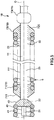
- Fig. 5 is an enlarged side view (partial cross-sectional view) illustrating a tubular portion and a support portion according to a third embodiment of a guide wire of the present invention.
- the distal side support portion 71 and the proximal side support portion 72 are configured to be respectively rotatable with respect to the wire main body 11.
- the distal side support portion 71 is configured to include a cylindrical member. In addition, the distal side support portion 71 is formed to be separate from the fixing member 43. In addition, the distal portion of the distal side support portion 71 has a tapered portion 713 whose outer diameter gradually decreases in a direction away from the coil 5, that is, toward the distal side. In the addition, the distal portion of the coil 5 is buried in and fixed to the distal side support portion 71.
- the proximal side support portion 72 is configured to include a cylindrical member.
- the proximal portion of the proximal side support portion 72 has a tapered portion 725 whose outer diameter gradually decreases toward the proximal side.
- the proximal portion of the coil 5 is buried in and fixed to the proximal side support portion 72.
- a support portion 7B has a ring-shaped restriction portion 73 disposed on the proximal side of the proximal side support portion 72 of the constant outer diameter portion 23 of the wire main body 11.
- the restriction portion 73 is fixed to the constant outer diameter portion. In this manner, the support portion 7B can be restricted so as not to move to the proximal side from the restriction portion 73.
- tapered portion 713 and the tapered portion 725 can more reliably prevent the coil 5 from riding on the coil 41 or riding on the restriction portion 73.
- the sliding resistance reduction processing as described in the first embodiment is performed on the inner peripheral surface of the distal side support portion 71 and the proximal side support portion 72. In this manner, the coil 5 can be more smoothly rotated.
- Fig. 6 is an enlarged cross-sectional view illustrating a tubular portion and a support portion according to a fourth embodiment of a guide wire of the present invention.
- a groove 26 is disposed in a boundary portion between the tapered portion 24 of the wire main body 11 and the constant outer diameter portion 25.
- the groove 26 is configured to include a ring-shaped groove formed along the circumferential direction of the wire main body 11.
- the wire rod 50 of the proximal portion of the coil 5 is inserted into the groove 26.
- an inserted portion of the wire rod 50 of the coil 5 is supported by the inner peripheral portion 261 of the groove 26 so as to be rotatable around the central axis O.
- the inserted portion of the wire rod 50 is restricted by the inner peripheral portion 261 of the groove 26 so as not to move to the proximal side.
- the groove 26 of the wire main body 11 functions as the proximal side support portion.
- an advantageous effect the same as that according to the first embodiment can be achieved, and the formation of the proximal side support portion 72 according to the first embodiment can be omitted. Therefore, manufacturing steps of the guide wire 1C can be simplified.
- the coil 5 is restricted so as not to move to the proximal side. Therefore, it is possible to further improve the operability.
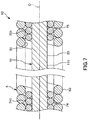
- Fig. 7 is an enlarged cross-sectional view illustrating a tubular portion and a support portion according to a fifth embodiment of a guide wire of the present invention.
- coils 74 and 75 are disposed between the constant outer diameter portion 23 of the wire main body 11 and the coil 5.
- the coil 74 is disposed between the distal portion of the coil 5 and the constant outer diameter portion 23.
- the coil 74 is a member in which a wire rod 741 is wound around the central axis O.
- the coil 74 is shorter in length than the coil 5, and an outer peripheral portion thereof is fixed to the coil 5.
- the coil 74 has an inner peripheral portion attached to the constant outer diameter portion 23, and is configured to be rotatable with respect to the wire main body 11.
- the coil 75 is disposed between the proximal portion of the coil 5 and the constant outer diameter portion 23.
- the coil 75 is a member in which a wire rod 751 is wound around the central axis O.
- the coil 75 is shorter in length than the coil 5, and an outer peripheral portion thereof is fixed to the coil 5 via an adhesive layer (not illustrated) .
- the coil 75 has an inner peripheral portion attached to the constant outer diameter portion 23, and is configured to be rotatable with respect to the wire main body 11.
- the coil 74 and the coil 75 may be formed integrally with the coil 5. That is, in the coil 5, the distal portion and the proximal portion may be configured so that the wire rod 50 is wound double and the doubled portions overlap each other in the radial direction. In this manner, manufacturing steps of the guide wire 1D can be further simplified.
- the guide wire according to the present invention has been described with reference to the embodiments illustrated in the drawings.
- the present invention is not limited thereto, and the configuration of each unit may be substituted with any desired configuration having the same function.
- any other desired configuration may be added to the present invention.
- the tubular portion is configured to include a coil.
- the present invention is not limited thereto.
- the tubular portion may be configured to include a tubular member or a member in which many rings are concentrically located and connected to each other.
- a cross-sectional shape of the wire rod configuring each of the coils has a circular shape.
- the present invention is not limited thereto.
- a semicircular shape or a flat shape may be used.
- the above-described respective embodiments adopt a configuration in which the support portion supports both end portions of the tubular portion.
- the present invention is not limited thereto.
- the support portion has a function to support at least one end portion of the distal portion and the proximal portion, the advantageous effect according to the present invention is achieved.
- a guide wire according to the present invention includes a flexible wire main body, a tubular portion that is intermediately disposed in a longitudinal direction of the wire main body in an outer periphery of the wire main body, and that has a tubular shape, and a support portion that supports at least one end portion of a distal portion and a proximal portion of the tubular portion from the inside so as to be rotatable around a central axis of the wire main body. Therefore, the tubular portion is configured to be rotatable with respect to the wire main body. Accordingly, for example, even if the tubular portion is caught by a stenosed site, the wire main body can be rotationally operated.
Landscapes
- Health & Medical Sciences (AREA)
- Life Sciences & Earth Sciences (AREA)
- Biophysics (AREA)
- Pulmonology (AREA)
- Engineering & Computer Science (AREA)
- Anesthesiology (AREA)
- Biomedical Technology (AREA)
- Heart & Thoracic Surgery (AREA)
- Hematology (AREA)
- Animal Behavior & Ethology (AREA)
- General Health & Medical Sciences (AREA)
- Public Health (AREA)
- Veterinary Medicine (AREA)
- Media Introduction/Drainage Providing Device (AREA)
Abstract
Description
- The present invention relates to a guide wire.
- A guide wire is used in order to a catheter used for treatment of a site having difficulties in surgery, minimally invasive treatment for a human body, or examination such as cardioangiography. For example, when percutaneous coronary intervention (PCI) is performed, in a state where a distal end of the guide wire is protruded from a distal end of a balloon catheter under X-ray fluoroscopy, the guide wire together with the balloon catheter is inserted into the vicinity of a stenosed site of a coronary artery which serves as a target site, and the distal portion of the balloon catheter is guided to the vicinity of the vascular stenosed site.
- For example, as the guide wire used for this treatment, a guide wire disclosed in PTL 1 is known. This guide wire has a flexible wire main body (core wire), a primary coil fixed to a distal portion of the wire main body, and a secondary coil disposed on a proximal side of the primary coil and installed so as to cover an outer periphery of the wire main body. This secondary coil is disposed so as not be fixed to the wire main body and the primary coil. Therefore, the secondary coil can be rotated independently of the wire main body and the primary coil. Accordingly, for example, even if the secondary coil is caught by the vascular stenosed site, the wire main body and the distal coil can be rotationally operated.
- However, according to the guide wire disclosed in PTL 1, the wire main body and the secondary coil are separated from each other, and a gap is formed therebetween. Therefore, in some cases, axial misalignment occurs between the wire main body and the secondary coil. That is, in some cases, the wire main body and the secondary coil are unintentionally misaligned from each other in a radial direction. Depending on a degree of this misalignment, there is a possibility that operability may become poor.
- [PTL 1]
JP-A-2002-143320 - An object of the present invention is to provide a guide wire capable of achieving excellent operability inside a steeply curved blood vessel or inside a vascular stenosed site.
- This object is achieved by the present invention described in the following (1) to (10).
- (1) There is provided a guide wire including a flexible wire main body,
a tubular portion that is intermediately disposed in a longitudinal direction of the wire main body in an outer periphery of the wire main body, and that has a tubular shape, and
a support portion that supports at least one of a distal portion and a proximal portion of the tubular portion from the inside so as to be rotatable around a central axis of the wire main body. - (2) In the guide wire in (1) described above, in a natural state where an external force is not applied to the guide wire, the support portion supports in a state where an inner peripheral portion of the tubular portion and an outer peripheral portion of the wire main body are separated from each other.
- (3) In the guide wire in (1) or (2) described above, the support portion is fixed to the wire main body.
- (4) In the guide wire in (3) described above, the tubular portion is configured to include a coil formed of a wire rod wound in a spiral shape.
The support portion has a cylindrical shape, and a spiral groove into which the wire rod is inserted is disposed in an outer peripheral portion of the support portion. - (5) The guide wire in (3) or (4) described above further includes a distal coil that is disposed on a distal side from the tubular portion in a distal outer peripheral portion of the wire main body, and a fixing portion that fixes a proximal portion of the distal coil to the wire main body.
The support portion is formed integrally with the fixing portion. - (6) In the guide wire in (1) or (2) described above, the support portion has a cylindrical shape, and is configured to be rotatable around the central axis of the wire main body with respect to the wire main body.
- (7) In the guide wire in (6) described above, the support portion and the tubular portion are fixed to each other.
- (8) The guide wire in (6) or (7) described above further includes a distal coil that is disposed on a distal side from the tubular portion in a distal outer peripheral portion of the wire main body.
The support portion has a cylindrical shape, and an inner diameter of the support portion is smaller than an outer diameter of the distal coil. - (9) In the guide wire in any one of (6) to (8) described above, the support portion has a tapered portion whose outer diameter gradually decreases in a direction away from the tubular portion.
- (10) The guide wire in any one of (1) to (9) described above further includes a restriction portion that restricts movement of the tubular portion in the longitudinal direction of the wire main body.
- According to the present invention, the tubular portion is configured to be rotatable with respect to the wire main body. Therefore, even if the tubular portion is caught by a stenosed site, the wire main body can be rotationally operated.
- In particular, the guide wire has the support portion that supports the tubular portion. Therefore, it is possible to prevent axial misalignment between the tubular portion and the wire main body. That is, it is possible to restrict a positional relationship between the tubular portion and the wire main body. As a result, it is possible to prevent the tubular portion and the wire main body from being unintentionally misaligned from each other in a radial direction. According to the above-described configurations, the guide wire according to the present invention is excellent in operability.
-
- [
Fig. 1] Fig. 1 is a longitudinal cross-sectional view (schematic side view) illustrating a first embodiment of a guide wire according to the present invention. - [
Fig. 2] Fig. 2 is an enlarged cross-sectional view of a tubular portion and a support portion which are illustrated inFig. 1 . - [
Fig. 3] Fig. 3 is an enlarged side view (partial cross-sectional view) illustrating a tubular portion and a support portion according to a second embodiment of a guide wire of the present invention. - [
Fig. 4] Fig. 4 is an enlarged side view (partial cross-sectional view) illustrating the tubular portion and the support portion in the second embodiment of the guide wire according to the present invention. - [
Fig. 5] Fig. 5 is an enlarged side view (partial cross-sectional view) illustrating a tubular portion and a support portion according to a third embodiment of a guide wire of the present invention. - [
Fig. 6] Fig. 6 is an enlarged cross-sectional view illustrating a tubular portion and a support portion according to a fourth embodiment of a guide wire of the present invention. - [
Fig. 7] Fig. 7 is an enlarged cross-sectional view illustrating a tubular portion and a support portion according to a fifth embodiment of a guide wire of the present invention. - Hereinafter, a guide wire according to the present invention will be described in detail with reference to preferred embodiments illustrated in the accompanying drawings.
-
Fig. 1 is a longitudinal cross-sectional view (schematic side view) illustrating a first embodiment of a guide wire according to the present invention.Fig. 2 is an enlarged cross-sectional view of a tubular portion and a support portion, which are illustrated inFig. 1 . Hereinafter, for convenience of description, a right side in a long axis direction inFigs. 1 and2 will be referred to as a "proximal end", a left side will be referred to as a "distal end", an upper side will be referred to as "upward", and a lower side will be referred to as "downward". In addition, in order to facilitate understanding,Figs. 1 and2 are schematically illustrated in such a manner that a length direction of the guide wire is shortened and a radial direction (thickness direction) of the guide wire is exaggerated. A ratio between the length direction and the radial direction is different from an actual ratio (the same in the drawings subsequent toFig. 3 ). In addition, the guide wire according to the present invention achieves excellent operability in, for example, a vascular stenosed site having a decreased distance between tube walls of a blood vessel, or a site having a steeply curved blood vessel. Hereinafter, a case where the guide wire according to the present invention is located inside the vascular stenosed site will be described as a representative example. - A guide wire 1 illustrated in
Fig. 1 is a catheter guide wire used by being inserted into a lumen of a catheter (including an endoscope), and includes afirst wire 2 located on a distal side, a flexible wiremain body 11 formed by joining (connecting) asecond wire 3 located on a proximal side of thefirst wire 2 to thefirst wire 2, adistal member 4 having acoil 41 fixed to a distal portion of the wiremain body 11 by usingfixing members coil 41, on an outer periphery of the wiremain body 11, and asupport portion 7. A total length of the guide wire 1 is not particularly limited. However, it is preferable that the total length is approximately 200 to 5,000 mm. In addition, an outer diameter of the guide wire 1 is not particularly limited. However, it is generally preferable that the outer diameter is approximately 0.2 to 1.2 mm. - The
first wire 2 is configured to include a flexible or elastic wire rod (core material) . A length of thefirst wire 2 is not particularly limited. However, it is preferable that the length is approximately 20 to 1,000 mm. - According to the present embodiment, the
first wire 2 has a portion whose outer diameter is constant (constant outer diameter portion), and a portion having a tapered shape whose outer diameter gradually decreases in a distal direction (gradually decreasing outer diameter portion) (tapered portion). In the illustrated configuration, sequentially from the proximal side to the distal side, thefirst wire 2 has a constantouter diameter portion 25, a tapered portion (proximal side tapered portion) 24, a constantouter diameter portion 23 having the outer diameter smaller than that of the constantouter diameter portion 25, a tapered portion (distal side tapered portion) 22, and a mostdistal portion 21. - The
first wire 2 has the taperedportions first wire 2 can be gradually reduced in the distal direction. As a result, the guide wire 1 is allowed to have satisfactory flexibility in the distal portion. Accordingly, followability to a body lumen (body-cavity) of the blood vessel and safety can be improved. Therefore, it is possible to prevent the guide wire 1 from being bent. - Each tapered angle of the tapered
portions 22 and 24 (reduction rate of the outer diameter) is constant along a longitudinal direction of the wire main body 11 (hereinafter, simply referred to as a "longitudinal direction"). However, there may be a portion changing along the longitudinal direction. For example, the wiremain body 11 may be formed so that a location having the relatively large tapered angle (reduction rate of the outer diameter) and a location having the relatively small tapered angle are alternately repeated multiple times. - For example, the most
distal portion 21 can be a constant outer diameter portion whose outer diameter is smaller than that of the constantouter diameter portion 23. - In addition, for example, the most
distal portion 21 may have a flat plate shape (ribbon shape), and may be configured to be deformable (reshaping: shaping available) into a desired shape. In general, in the guide wire, in order to allow the distal portion of a guiding catheter to correspond to a shape of the blood vessel or to smoothly guide the distal portion to a branch of the blood vessel, a physician uses the guide wire by bending the distal portion of the guide wire in advance into a desired shape in some cases. Bending the distal portion of the guide wire into the desired shape in this way is called reshaping. Then, since the mostdistal portion 21 is provided, the reshaping can be easily and reliably performed. Accordingly, operability is remarkably improved when the guide wire 1 is inserted into a living body. - The length of the most
distal portion 21 is not particularly limited. However, it is preferable that the length is approximately 5 to 200 mm, and more preferably approximately 10 to 150 mm. - A configuration material (material) of the
first wire 2 is not particularly limited. For example, various metal materials such as a Ni-Ti alloy and stainless steel can be used. However, it is preferable to use a pseudo-elastic alloy (including a super-elastic alloy). It is more preferable to use the super-elastic alloy. The super-elastic alloy is comparatively flexible, has resilience, and is less likely to be bent. Accordingly, thefirst wire 2 is configured to include the super-elastic alloy. In this manner, the guide wire 1 is formed so that a distal side portion is allowed to obtain sufficient flexibility and the resilience against bending. Accordingly, followability to a complicatedly curved and bent blood vessel is improved, and more excellent operability can be obtained. Even if thefirst wire 2 is deformed after being repeatedly curved and bent, the resilience of thefirst wire 2 allows thefirst wire 2 to be unlikely to be bent. Therefore, it is possible to prevent poor operability caused by thefirst wire 2 which is likely to be bent when the guide wire 1 is used. - The distal end of the
second wire 3 is joined (connected) to the proximal end (proximal end of the constant outer diameter portion 25) of thefirst wire 2. Thesecond wire 3 is configured to include a highly rigid wire rod (core material) . The length of thesecond wire 3 is not particularly limited. However, it is preferable that the length is approximately 20 to 4,800 mm, and more preferably approximately 1,400 to 3,000 mm. - A method of joining the
first wire 2 and thesecond wire 3 to each other is not particularly limited. For example, various methods welding and brazing can be used. However, it is preferable that thefirst wire 2 and thesecond wire 3 are joined by using the welding. - The
second wire 3 is configured to include a material different from that of thefirst wire 2. In particular, it is preferable that thesecond wire 3 is configured to include a material having an elastic modulus (Young's modulus (longitudinal elastic modulus), a modulus of rigidity (modulus of transverse elasticity), and a bulk modulus) which is higher than the configuration material of thefirst wire 2. In this manner, rigidity (flexural rigidity or torsional rigidity) suitable for thesecond wire 3 is obtained, and the guide wire 1 is allowed to have a so-called strong body. Accordingly, pushing performance and torque transmission performance are improved, thereby achieving more excellent operability. - A configuration material (material) of the
second wire 3 is not particularly limited as long as the configuration material of thesecond wire 3 is different from that of thefirst wire 2. It is possible to use various metal materials such as stainless steel (for example, all SUS types such as SUS 304, SUS 303, SUS 316, SUS 316L, SUS316J1, SUS 316J1L, SUS 405, SUS 430, SUS 434, SUS 444, SUS 429, SUS 430F, and SUS302), a piano wire, a cobalt alloy, and a pseudo-elastic alloy. However, it is preferable to use the stainless steel or the cobalt alloy, and is more preferable to use the stainless steel. Since thesecond wire 3 is configured to include the stainless steel or the cobalt alloy, the guide wire 1 can obtain the more excellent pushing performance and torque transmission performance. - According to the present embodiment, the wire
main body 11 is formed by joining thefirst wire 2 and thesecond wire 3 to each other. However, for example, without being limited thereto, the wiremain body 11 may be configured to include one continuous wire rod. - As illustrated in
Fig. 1 , thecoil 41 whose outer diameter and inner diameter are constant is installed in a distal portion outer periphery of the wiremain body 11, that is, the mostdistal portion 21 of thefirst wire 2 and the outer periphery of the distal portion of the taperedportion 22. Thecoil 41 is a member formed by winding awire rod 40 in a spiral shape, and is installed so as to cover the distal portion of the wiremain body 11, that is, the mostdistal portion 21 of thefirst wire 2, and a portion except for the proximal portion of the taperedportion 22. In addition, thefirst wire 2 is inserted into a substantially central portion inside thecoil 41 in a non-contact manner. - The length (length of the wire
main body 11 in the longitudinal direction) of thecoil 41 is preferably 5 to 500 mm, and more preferably 10 to 300 mm. In addition, the inner diameter (inner diameter of the wiremain body 11 in a circumferential direction) of thecoil 41 is preferably 0.1 to 0.95 mm, and more preferably 0.2 to 0.7 mm. - It is preferable that this
coil 41 is configured to include a metal material. For example, the metal material configuring thecoil 41 includes stainless steel, a super-elastic alloy, a cobalt alloy, noble metal such as gold, platinum, and tungsten, or an alloy containing these materials (for example, a platinum-iridium alloy). In particular, in a case where thecoil 41 is configured to include a radiopaque material such as noble metal, the guide wire 1 is allowed to have X-ray contrast ability. While a position of the distal portion is confirmed under X-ray fluoroscopy, the guide wire 1 can be preferably inserted into a living body. In addition, in thecoil 41, the distal side and the proximal side may be configured to include mutually different materials. For example, the distal side may be configured to include a coil formed of a radiopaque material, and the proximal side may be configured a coil formed of a material (such as stainless steel) through which X-rays are relatively transmitted. - The distal portion and the proximal portion of the
coil 41 are respectively fixed to thefirst wire 2 by the fixingmember 42 and the fixingmember 43. The fixingmember 42 is disposed in the mostdistal portion 21. In addition, the fixingmember 43 is disposed in the taperedportion 22. - These fixing
members member 42 and the fixingmember 43 may be an adhesive. In addition, the fixing method of thecoil 41 is not limited to the method of using the fixing member. For example, the fixing method may be welding. In addition, in order to prevent damage to an inner wall of a body-cavity such as the blood vessel, it is preferable that a distal surface of the fixingmember 42 is rounded. - Since this
coil 41 is installed, the distal portion of the guide wire 1 is allowed to obtain suitable flexibility is obtained. In addition, thefirst wire 2 is covered by thecoil 41. In this manner, for example, a contact area with the blood vessel decreases. Accordingly, sliding resistance can be reduced. Therefore, operability of the guide wire 1 is further improved. - The
coil 5 is disposed on the proximal side of thecoil 41 on the outer periphery of the wiremain body 11. - The
coil 5 is a member formed by winding awire rod 50, and is disposed so as to cover the proximal portion of the taperedportion 22 and the constantouter diameter portion 23. In addition, thewire rod 50 is a so-called "densely" wound body in which adjacent portions along the longitudinal direction of the guide wire 1 are in contact with each other. - In addition, the
coil 5 is disposed so as not to be fixed to the wiremain body 11 throughout the entire length in the longitudinal direction of thecoil 5, and is also disposed so as not to be fixed to the distal member 4 (thecoil 41 and the fixing member 43). In this manner, thecoil 5 can be rotated independently of the wiremain body 11 and thecoil 41 throughout the entire length in the longitudinal direction. - It is preferable that the length of the
coil 5 is longer than the length of thecoil 41. Specifically, the length of thecoil 5 is preferably 10 to 500 mm, and more preferably 50 to 300 mm. In addition, the length of thecoil 5 is preferably 0.3% to 30% of the length of the wiremain body 11, and more preferably 1.5% to 15%. In this manner, the guide wire 1 can receive a vascularstenosed site 100 by using thecoil 5 as much as possible. When the guide wire 1 is used, thecoil 5 is in a state of being inserted into a body lumen such as the blood vessel. - In addition, it is preferable that the inner diameter and the outer diameter of the
coil 5 are equal to those of thecoil 41. In particular, since the outer diameter of thecoil 5 is equal to the outer diameter of thecoil 41, when the whole guide wire 1 is viewed, it is possible to prevent or restrain a step difference from being formed in the outer periphery of the guide wire 1. Accordingly, for example, it is possible to prevent the guide wire 1 from being caught on other medical instruments such as catheters or the blood vessel. - Sliding resistance reduction processing for reducing sliding resistance between the
coil 5 and the wiremain body 11 may be performed on the innerperipheral portion 51 of thecoil 5. According to the present embodiment, ahydrophilic lubricant layer 52 configured to include a hydrophilic material is coated on the inner peripheral surface of the coil 5 (refer toFigs. 1 and2 ). In this manner, the hydrophilic material is moistened and lubricated, thereby reducing friction (sliding resistance) between thecoil 5 and the wiremain body 11. Therefore, sliding performance is improved. - For example, the hydrophilic material (configuration material of the hydrophilic lubricant layer 52) includes a cellulose-based polymer material, a polyethylene oxide-based polymer material, a maleic anhydride-based polymer material (for example, a methyl vinyl ether-maleic anhydride copolymer such as a maleic anhydride copolymer), an acrylamide polymer material (for example, a block copolymer of polyacrylamide glycidyl methacrylate-dimethyl acrylamide (PGMA-DMAA)), water-soluble nylon, polyvinyl alcohol, and polyvinyl pyrrolidone.
- According to the present embodiment, the
hydrophilic lubricant layer 52 is disposed in the innerperipheral portion 51 of thecoil 5, but may be disposed in the whole outerperipheral portion 111 of the wiremain body 11. Furthermore, thehydrophilic lubricant layer 52 may be disposed in the outer peripheral portion of thecoil 5. In this manner, the frictional resistance (sliding resistance) against the inner wall of the catheter used together with the guide wire 1 is reduced. Accordingly, the sliding performance of the guide wire 1 is improved, and the operability of the guide wire 1 inside the catheter is more satisfactorily achieved. - Hitherto, the example has been described in which the hydrophilic material is used as the sliding resistance reduction processing material. However, the present invention is not limited thereto. For example, a fluorine-based resin or a silicon-based resin may be used. The fluorine-based resin includes polytetrafluoroethylene (PTFE), ethylene-tetrafluoroethylene copolymer (ETFE), and tetrafluoroethylene-perfluoroalkylvinylether copolymer (PFA). In addition, for example, the silicon-based resin includes a silicone resin. Furthermore, a composite material thereof may be used.
- In addition, the guide wire 1 has
resin coating layers main body 11. In the illustrated configuration, theresin coating layer 9 is disposed on an outer periphery of a joint portion 6 of the wiremain body 11, and theresin coating layer 8 is disposed in the outer peripheral portion on the proximal side therefrom. - The
resin coating layers - In order to reduce the frictional resistance (sliding resistance) of the guide wire 1, it is preferable that the
resin coating layers first wire 2 and thesecond wire 3 can be more reliably prevented. - For example, a material configuring the
resin coating layers - Particularly, in a case of using the fluororesin (or a composite material containing the fluororesin) among the above-described materials, the frictional resistance (sliding resistance) between the guide wire 1 and the inner wall of the catheter is more effectively reduced. Accordingly, the sliding performance can be improved, and the operability of the guide wire 1 inside the catheter is more satisfactorily achieved. In addition, in this manner, when the guide wire 1 is moved and/or rotated inside the catheter, kink (bending) or twist of the guide wire 1, especially kink and twist in the vicinity of a welded portion, can be more reliably prevented.
- In addition, in a case of using the fluorine resin (or a composite material containing the fluorine resin), it is possible to coat the wire
main body 11 with the fluorine resin in a state where the resin material is heated by burning or blowing. In this manner, adhesion between the wiremain body 11 and theresin coating layers - In addition, if the
resin coating layers resin coating layers resin coating layer 8 reliably and firmly adhering to the wiremain body 11 can be formed without heating. That is, in a case where theresin coating layers resin coating layers resin coating layers - The materials configuring the
resin coating layers - A thickness of the
resin coating layers resin coating layers resin coating layers resin coating layers resin coating layers resin coating layers resin coating layers main body 11 may be affected. In addition, there is a possibility that theresin coating layers - The
resin coating layers - In addition, according to the present invention, on the outer peripheral surface (surface) of the wire
main body 11, processing (rough surface processing, chemical treatment, or heat treatment) for improving the adhesion of theresin coating layers resin coating layers - The guide wire 1 has the
support portion 7 which supports thecoil 5 from the inside so as to be rotatable around the central axis O of the wiremain body 11 with respect to the wiremain body 11. Thesupport portion 7 has a distalside support portion 71 that supports the distal portion of thecoil 5, and a proximalside support portion 72 that supports the proximal portion of thecoil 5. - As illustrated in
Figs. 1 and2 , the distalside support portion 71 is formed to protrude to the proximal side from a fixing membermain body 431 for fixing thecoil 41 of the fixingmember 43, and is fixed to the wiremain body 11. - The distal
side support portion 71 has a cylindrical shape, and is inserted into the distal portion of thecoil 5. In addition, the distalside support portion 71 is disposed so as not to be fixed to thecoil 5, and supports thecoil 5 by being attached to thecoil 5. - In addition, the outer diameter of the distal
side support portion 71 is smaller than the outer diameter of the fixing membermain body 431. In the manner, a stepped portion (restriction portion) 711 is formed between the fixing membermain body 431 and the distalside support portion 71. - The proximal
side support portion 72 is located on the proximal side from the distalside support portion 71. In addition, the proximalside support portion 72 is configured to include a cylindrical member into which the constantouter diameter portion 23 of the wiremain body 11 is inserted. The proximalside support portion 72 is fixed to the wiremain body 11. - The proximal
side support portion 72 has a constantouter diameter portion 721 whose outer diameter is constant and atapered portion 722 having a tapered shape. - The constant
outer diameter portion 721 has an outer diameter substantially equal to an inner diameter of thecoil 5, and is inserted into the proximal portion of thecoil 5. In addition, the constantouter diameter portion 721 is disposed so as not to be fixed to thecoil 5, and supports thecoil 5 by being attached to thecoil 5. - The tapered
portion 722 has the largest outer diameter on the distal side, and has the smallest outer diameter on the proximal side. In addition, the taperedportion 722 has an outer diameter, which continuously and gradually decreases toward the proximal side. In this manner, it is possible to prevent a steep step difference from being formed between thetapered portion 722 and the wiremain body 11. Accordingly, for example, it is possible to prevent the guide wire 1 from being caught on other medical instruments such as catheters or the blood vessel. - In addition, the largest outer diameter of the distal end of the tapered
portion 722 is larger than the outer diameter of the constantouter diameter portion 721. In the manner, a stepped portion (restriction portion) 723 is formed in a boundary between the constantouter diameter portion 721 and the taperedportion 722. - The distal
side support portion 71 and the proximalside support portion 72 allow thecoil 5 to be rotated around the central axis O with respect to the wiremain body 11 throughout the entire length of thecoil 5. In this manner, as illustrated inFig. 1 , even if thecoil 5 is caught by the vascularstenosed site 100, if the proximal portion of the guide wire 1 is rotationally operated, the wiremain body 11 and thedistal member 4 can be rotated with respect to thecoil 5. Accordingly, even in a state as illustrated inFig. 1 , the rotational operation can be performed, and an orientation of the distal portion of the guide wire 1 can be changed. As a result, the guide wire 1 can achieve excellent operability even inside the vascularstenosed site 100. - In the above description, as an example, a case has been described where the rotational operation is performed inside the vascular
stenosed site 100. However, although not illustrated, the rotational operation can be similarly performed even inside a steeply curved blood vessel. Accordingly, the guide wire 1 can achieve the excellent operability. - In particular, in a natural state where an external force is not applied to the guide wire 1, the
support portion 7 supports a state where the innerperipheral portion 51 of thecoil 5 and the outerperipheral portion 111 of the wiremain body 11 are separated from each other. In this manner, even if thecoil 5 and the wiremain body 11 come into contact with each other, it is possible to prevent or restrain both of these from inhibiting relative rotation. - Furthermore, in the
coil 5, the distalside support portion 71 and the proximalside support portion 72 prevents thecoil 5 from being misaligned with the wiremain body 11 in the radial direction, that is, the axial misalignment is prevented. In this manner, it is possible to restrict a positional relationship in the radial direction between thecoil 5 and the wiremain body 11. Accordingly, when the guide wire 1 is viewed as a whole, it is possible to prevent a step difference from being formed due to the misalignment between thecoil 5 and the wiremain body 11 in the radial direction. As a result, for example, it is possible to prevent the guide wire 1 from being caught on other medical instruments such as catheters or the blood vessel. - In addition, even if the external force is applied in a direction in which the
coil 5 moves to the distal side from the position illustrated inFigs. 1 and2 , the distal portion of thecoil 5 is attached to the steppedportion 711 formed in the boundary between the distalside support portion 71 and the fixing membermain body 431. In this manner, thecoil 5 can be prevented from moving to the distal side further from the steppedportion 711. That is, it is possible to restrict the movement of thecoil 5 to the distal side. As a result, it is possible to prevent thecoil 5 from riding on the fixing membermain body 431 or thecoil 41. - In addition, conversely, even if the external force is applied in a direction that the
coil 5 moves to the proximal side from the position illustrated inFigs. 1 and2 , the proximal portion of thecoil 5 is attached to the steppedportion 723 formed between the constantouter diameter portion 721 and the taperedportion 722. In this manner, thecoil 5 can be prevented from moving to the proximal side further from the steppedportion 723. That is, it is possible to restrict the movement of thecoil 5 to the proximal side. As a result, it is possible to prevent thecoil 5 from riding on the taperedportion 24 of the wiremain body 11 or the constantouter diameter portion 25. - A configuration material of the distal
side support portion 71 and the proximalside support portion 72 is not particularly limited. However, it is preferable to use a configuration material the same as that of the fixingmember 42 and the fixingmember 43. In this manner, in a step of forming the fixingmember 42 and the fixingmember 43, the distalside support portion 71 and the proximalside support portion 72 can be formed. That is, in a step of fixing thecoil 41 to the wiremain body 11, thecoil 5 can be supported by the wiremain body 11. Accordingly, steps of manufacturing the guide wire 1 can be simplified. - In addition, the fixing
member 43 may be divided into a portion for fixing thecoil 41 and a portion loosely fitted to thecoil 5. In this manner, thecoil 5 is more smoothly rotated. -
Figs. 3 and 4 are enlarged side views (partial cross-sectional views) illustrating a tubular portion and a support portion according to a second embodiment of a guide wire of the present invention. - As illustrated in
Figs. 3 and 4 , in asupport portion 7A of aguide wire 1A, the distalside support portion 71 has agroove 712, and the proximalside support portion 72 has agroove 724. - The
groove 712 is formed in a spiral shape around the central axis O in the outer peripheral portion of the distalside support portion 71. Thegroove 712 corresponds to a spiral shape of thewire rod 50 of thecoil 5. A portion of thewire rod 50 of thecoil 5 enters thegroove 712. As thecoil 5 is rotated, thewire rod 50 slides inside thegroove 712, and thecoil 5 can move in a direction of the central axis. - The
groove 724 is formed in a spiral shape around the central axis O in the outer peripheral portion of the proximalside support portion 72. In addition, in thegroove 724, portions adjacent to each other in the direction of the central axis O do not communicate with each other. Thegroove 724 corresponds to the spiral shape of thewire rod 50 of thecoil 5. A portion of thewire rod 50 of thecoil 5 enters thegroove 724. As thecoil 5 is rotated, thewire rod 50 slides inside thegroove 724, and thecoil 5 can move in the direction of the central axis O. - In this
guide wire 1A, it is possible to bring theguide wire 1A into a state where thecoil 5 is rotated with respect to the wiremain body 11 and moves to the distal side with respect to the wire main body 11 (refer toFig. 3 ) and a state where thecoil 5 is rotated to the opposite side and moves to the proximal side with respect to the wire main body 11 (refer toFig. 4 ). - In addition, as illustrated in
Fig. 3 , in a state where thecoil 5 moves to the most distal side with respect to the wiremain body 11, the steppedportion 711 restricts thecoil 5 so as not to further move to the distal side. In this case, the proximal portion of thecoil 5 is supported by the proximalside support portion 72. - On the other hand, as illustrated in
Fig. 4 , in a state where thecoil 5 moves to the most proximal side with respect to the wiremain body 11, the steppedportion 723 restricts thecoil 5 so as not to further move to the proximal side. In this case, the distal portion of thecoil 5 is supported by the distalside support portion 71. - In this way, in the
guide wire 1A, regardless of the position in the longitudinal direction in theguide wire 1A, thecoil 5 is brought into a state where both ends of thecoil 5 are reliably supported by thesupport portion 7A. Accordingly, it is possible to prevent the axial misalignment from occurring between thecoil 5 and the wiremain body 11. - In particular, in the
guide wire 1A, even if a force is applied to thecoil 5 in a direction in which thecoil 5 moves in the direction of the central axis O, as long as the force is not applied in a direction in which thecoil 5 is rotated, thecoil 5 is prevented from moving along the central axis O. In this manner, unintentional movement of thecoil 5 in the direction of the central axis O can be restrained as much as possible. -
Fig. 5 is an enlarged side view (partial cross-sectional view) illustrating a tubular portion and a support portion according to a third embodiment of a guide wire of the present invention. - In a
support portion 7B of aguide wire 1B, the distalside support portion 71 and the proximalside support portion 72 are configured to be respectively rotatable with respect to the wiremain body 11. - The distal
side support portion 71 is configured to include a cylindrical member. In addition, the distalside support portion 71 is formed to be separate from the fixingmember 43. In addition, the distal portion of the distalside support portion 71 has a taperedportion 713 whose outer diameter gradually decreases in a direction away from thecoil 5, that is, toward the distal side. In the addition, the distal portion of thecoil 5 is buried in and fixed to the distalside support portion 71. - The proximal
side support portion 72 is configured to include a cylindrical member. In addition, the proximal portion of the proximalside support portion 72 has a taperedportion 725 whose outer diameter gradually decreases toward the proximal side. In the addition, the proximal portion of thecoil 5 is buried in and fixed to the proximalside support portion 72. - In addition, a
support portion 7B has a ring-shapedrestriction portion 73 disposed on the proximal side of the proximalside support portion 72 of the constantouter diameter portion 23 of the wiremain body 11. Therestriction portion 73 is fixed to the constant outer diameter portion. In this manner, thesupport portion 7B can be restricted so as not to move to the proximal side from therestriction portion 73. - In this
guide wire 1B, when a force is applied in a direction in which thecoil 5 is rotated around the central axis O, while thecoil 5 is supported by the distalside support portion 71 and the proximalside support portion 72, thecoil 5 is rotated together with the distalside support portion 71 and the proximalside support portion 72 with respect to the wiremain body 11. In this manner, thecoil 5 can be more stably rotated. As a result, it is possible to more reliably prevent the axial misalignment from occurring between thecoil 5 and the wiremain body 11. - Furthermore, the tapered
portion 713 and the taperedportion 725 can more reliably prevent thecoil 5 from riding on thecoil 41 or riding on therestriction portion 73. - Although not illustrated, according to the present embodiment, it is preferable that the sliding resistance reduction processing as described in the first embodiment is performed on the inner peripheral surface of the distal
side support portion 71 and the proximalside support portion 72. In this manner, thecoil 5 can be more smoothly rotated. -
Fig. 6 is an enlarged cross-sectional view illustrating a tubular portion and a support portion according to a fourth embodiment of a guide wire of the present invention. - In a
guide wire 1C, agroove 26 is disposed in a boundary portion between the taperedportion 24 of the wiremain body 11 and the constantouter diameter portion 25. Thegroove 26 is configured to include a ring-shaped groove formed along the circumferential direction of the wiremain body 11. Thewire rod 50 of the proximal portion of thecoil 5 is inserted into thegroove 26. In this state, an inserted portion of thewire rod 50 of thecoil 5 is supported by the innerperipheral portion 261 of thegroove 26 so as to be rotatable around the central axis O. Furthermore, in this state, the inserted portion of thewire rod 50 is restricted by the innerperipheral portion 261 of thegroove 26 so as not to move to the proximal side. - In this way, according to the
guide wire 1C, thegroove 26 of the wiremain body 11 functions as the proximal side support portion. In this manner, an advantageous effect the same as that according to the first embodiment can be achieved, and the formation of the proximalside support portion 72 according to the first embodiment can be omitted. Therefore, manufacturing steps of theguide wire 1C can be simplified. Furthermore, according to the present embodiment, thecoil 5 is restricted so as not to move to the proximal side. Therefore, it is possible to further improve the operability. -
Fig. 7 is an enlarged cross-sectional view illustrating a tubular portion and a support portion according to a fifth embodiment of a guide wire of the present invention. - In a
guide wire 1D, coils 74 and 75 are disposed between the constantouter diameter portion 23 of the wiremain body 11 and thecoil 5. - The
coil 74 is disposed between the distal portion of thecoil 5 and the constantouter diameter portion 23. Thecoil 74 is a member in which awire rod 741 is wound around the central axis O. Thecoil 74 is shorter in length than thecoil 5, and an outer peripheral portion thereof is fixed to thecoil 5. In addition, thecoil 74 has an inner peripheral portion attached to the constantouter diameter portion 23, and is configured to be rotatable with respect to the wiremain body 11. - The
coil 75 is disposed between the proximal portion of thecoil 5 and the constantouter diameter portion 23. Thecoil 75 is a member in which awire rod 751 is wound around the central axis O. Thecoil 75 is shorter in length than thecoil 5, and an outer peripheral portion thereof is fixed to thecoil 5 via an adhesive layer (not illustrated) . In addition, thecoil 75 has an inner peripheral portion attached to the constantouter diameter portion 23, and is configured to be rotatable with respect to the wiremain body 11. - In this
guide wire 1D, while thecoil 5 is supported by thecoils coil 5 together with thecoil 74 and thecoil 75 can be rotated with respect to the wiremain body 11. Accordingly, it is possible to achieve an advantageous effect the same as that of the above-described respective embodiments. - The
coil 74 and thecoil 75 may be formed integrally with thecoil 5. That is, in thecoil 5, the distal portion and the proximal portion may be configured so that thewire rod 50 is wound double and the doubled portions overlap each other in the radial direction. In this manner, manufacturing steps of theguide wire 1D can be further simplified. - Hitherto, the guide wire according to the present invention has been described with reference to the embodiments illustrated in the drawings. However, the present invention is not limited thereto, and the configuration of each unit may be substituted with any desired configuration having the same function. In addition, any other desired configuration may be added to the present invention.
- In the respective embodiments, a case has been described where the tubular portion is configured to include a coil. However, the present invention is not limited thereto. For example, the tubular portion may be configured to include a tubular member or a member in which many rings are concentrically located and connected to each other.
- In addition, according to the above-described respective embodiments, a cross-sectional shape of the wire rod configuring each of the coils has a circular shape. However, the present invention is not limited thereto. For example, a semicircular shape or a flat shape may be used.
- In addition, the above-described respective embodiments adopt a configuration in which the support portion supports both end portions of the tubular portion. The present invention is not limited thereto. As long as the support portion has a function to support at least one end portion of the distal portion and the proximal portion, the advantageous effect according to the present invention is achieved.
- A guide wire according to the present invention includes a flexible wire main body, a tubular portion that is intermediately disposed in a longitudinal direction of the wire main body in an outer periphery of the wire main body, and that has a tubular shape, and a support portion that supports at least one end portion of a distal portion and a proximal portion of the tubular portion from the inside so as to be rotatable around a central axis of the wire main body. Therefore, the tubular portion is configured to be rotatable with respect to the wire main body. Accordingly, for example, even if the tubular portion is caught by a stenosed site, the wire main body can be rotationally operated.
-
- 1, 1A, 1B, 1C, 1D
- guide wire
- 11
- wire main body
- 111
- outer peripheral portion
- 2
- first wire
- 21
- most distal portion
- 22, 24
- tapered portion
- 23, 25
- constant outer diameter portion
- 26
- groove
- 261
- inner peripheral portion
- 3
- second wire
- 4
- distal member
- 40
- wire rod
- 41
- coil
- 42, 43
- fixing member
- 431
- fixing member main body
- 5
- coil
- 50
- wire rod
- 51
- inner peripheral portion
- 52
- hydrophilic lubricant layer
- 6
- joint portion
- 7, 7A, 7B
- support portion
- 71
- distal side support portion
- 711
- stepped portion
- 712
- groove
- 713, 722, 725
- tapered portion
- 72
- proximal side support portion
- 721
- constant outer diameter portion
- 723
- stepped portion
- 724
- groove
- 73
- restriction portion
- 74, 75
- coil
- 741, 751
- wire rod
- 8, 9
- resin coating layer
- 100
- vascular stenosed site
- O
- central axis
Claims (10)
- A guide wire comprising:a flexible wire main body;a tubular portion that is intermediately disposed in a longitudinal direction of the wire main body in an outer periphery of the wire main body, and that has a tubular shape; anda support portion that supports at least one of a distal portion and a proximal portion of the tubular portion from the inside so as to be rotatable around a central axis of the wire main body.
- The guide wire according to Claim 1,
wherein in a natural state where an external force is not applied to the guide wire, the support portion supports in a state where an inner peripheral portion of the tubular portion and an outer peripheral portion of the wire main body are separated from each other. - The guide wire according to Claim 1 or 2,
wherein the support portion is fixed to the wire main body. - The guide wire according to Claim 3,
wherein the tubular portion is configured to include a coil formed of a wire rod wound in a spiral shape, and
wherein the support portion has a cylindrical shape, and a spiral groove into which the wire rod is inserted is disposed in an outer peripheral portion of the support portion. - The guide wire according to Claim 3 or 4, further comprising:a distal coil that is disposed on a distal side from the tubular portion in a distal outer peripheral portion of the wire main body; anda fixing portion that fixes a proximal portion of the distal coil to the wire main body,wherein the support portion is formed integrally with the fixing portion.
- The guide wire according to Claim 1 or 2,
wherein the support portion has a cylindrical shape, and is configured to be rotatable around the central axis of the wire main body with respect to the wire main body. - The guide wire according to Claim 6,
wherein the support portion and the tubular portion are fixed to each other. - The guide wire according to Claim 6 or 7, further comprising:a distal coil that is disposed on a distal side from the tubular portion in a distal outer peripheral portion of the wire main body,wherein the support portion has a cylindrical shape, and an inner diameter of the support portion is smaller than an outer diameter of the distal coil.
- The guide wire according to any one of Claims 6 to 8,
wherein the support portion has a tapered portion whose outer diameter gradually decreases in a direction away from the tubular portion. - The guide wire according to any one of Claims 1 to 9, further comprising:
a restriction portion that restricts movement of the tubular portion in the longitudinal direction of the wire main body.
Applications Claiming Priority (2)
| Application Number | Priority Date | Filing Date | Title |
|---|---|---|---|
| JP2016038380 | 2016-02-29 | ||
| PCT/JP2016/083565 WO2017149843A1 (en) | 2016-02-29 | 2016-11-11 | Guide wire |
Publications (3)
| Publication Number | Publication Date |
|---|---|
| EP3424551A1 true EP3424551A1 (en) | 2019-01-09 |
| EP3424551A4 EP3424551A4 (en) | 2019-10-30 |
| EP3424551B1 EP3424551B1 (en) | 2024-03-06 |
Family
ID=59743724
Family Applications (1)
| Application Number | Title | Priority Date | Filing Date |
|---|---|---|---|
| EP16892679.8A Active EP3424551B1 (en) | 2016-02-29 | 2016-11-11 | Guide wire |
Country Status (4)
| Country | Link |
|---|---|
| US (1) | US10850074B2 (en) |
| EP (1) | EP3424551B1 (en) |
| JP (1) | JP6765415B2 (en) |
| WO (1) | WO2017149843A1 (en) |
Cited By (5)
| Publication number | Priority date | Publication date | Assignee | Title |
|---|---|---|---|---|
| US12403296B2 (en) | 2018-05-30 | 2025-09-02 | Kardion Gmbh | Apparatus for anchoring a ventricular assist system in a blood vessel, operating method, production method for producing an apparatus and ventricular assist system |
| US12478775B2 (en) | 2018-07-09 | 2025-11-25 | Kardion Gmbh | Cardiac assist system, and method for monitoring the integrity of a retaining structure of a cardiac assist system |
| US12576263B2 (en) | 2018-05-30 | 2026-03-17 | Kardion Gmbh | Device for attaching a heart support system to an insertion device, and method for producing same |
| US12589237B2 (en) | 2020-11-20 | 2026-03-31 | Kardion Gmbh | Mechanical circulatory support system with guidewire aid |
| US12599749B2 (en) | 2018-05-30 | 2026-04-14 | Kardion Gmbh | Controllable insertion sleeve |
Families Citing this family (4)
| Publication number | Priority date | Publication date | Assignee | Title |
|---|---|---|---|---|
| WO2020162287A1 (en) * | 2019-02-06 | 2020-08-13 | 株式会社カネカ | Extension catheter and method for producing same |
| JP7580905B2 (en) * | 2019-06-07 | 2024-11-12 | 株式会社パイオラックスメディカルデバイス | Guidewire and method of manufacturing same |
| US20240009429A1 (en) * | 2022-07-05 | 2024-01-11 | Micro-Tech Endoscopy USA Inc. | Guidewire |
| JP2024104023A (en) * | 2023-01-23 | 2024-08-02 | 日本発條株式会社 | Guidewires |
Family Cites Families (5)
| Publication number | Priority date | Publication date | Assignee | Title |
|---|---|---|---|---|
| US5273052A (en) * | 1992-01-08 | 1993-12-28 | Danforth Biomedical, Incorporated | Guidewire with reversible contact seal for releasable securement to catheter |
| US5372144A (en) * | 1992-12-01 | 1994-12-13 | Scimed Life Systems, Inc. | Navigability improved guidewire construction and method of using same |
| JP4680372B2 (en) * | 2000-11-15 | 2011-05-11 | 川澄化学工業株式会社 | Guide wire |
| US20050027309A1 (en) * | 2003-06-17 | 2005-02-03 | Samuel Shiber | Guidewire system |
| JP6082807B2 (en) * | 2013-04-01 | 2017-02-15 | テルモ株式会社 | Guide wire |
-
2016
- 2016-11-11 EP EP16892679.8A patent/EP3424551B1/en active Active
- 2016-11-11 WO PCT/JP2016/083565 patent/WO2017149843A1/en not_active Ceased
- 2016-11-11 JP JP2018502520A patent/JP6765415B2/en active Active
-
2018
- 2018-08-03 US US16/054,030 patent/US10850074B2/en active Active
Cited By (5)
| Publication number | Priority date | Publication date | Assignee | Title |
|---|---|---|---|---|
| US12403296B2 (en) | 2018-05-30 | 2025-09-02 | Kardion Gmbh | Apparatus for anchoring a ventricular assist system in a blood vessel, operating method, production method for producing an apparatus and ventricular assist system |
| US12576263B2 (en) | 2018-05-30 | 2026-03-17 | Kardion Gmbh | Device for attaching a heart support system to an insertion device, and method for producing same |
| US12599749B2 (en) | 2018-05-30 | 2026-04-14 | Kardion Gmbh | Controllable insertion sleeve |
| US12478775B2 (en) | 2018-07-09 | 2025-11-25 | Kardion Gmbh | Cardiac assist system, and method for monitoring the integrity of a retaining structure of a cardiac assist system |
| US12589237B2 (en) | 2020-11-20 | 2026-03-31 | Kardion Gmbh | Mechanical circulatory support system with guidewire aid |
Also Published As
| Publication number | Publication date |
|---|---|
| EP3424551B1 (en) | 2024-03-06 |
| US10850074B2 (en) | 2020-12-01 |
| US20180369542A1 (en) | 2018-12-27 |
| WO2017149843A1 (en) | 2017-09-08 |
| JPWO2017149843A1 (en) | 2018-12-20 |
| EP3424551A4 (en) | 2019-10-30 |
| JP6765415B2 (en) | 2020-10-07 |
Similar Documents
| Publication | Publication Date | Title |
|---|---|---|
| EP3424551B1 (en) | Guide wire | |
| US11712544B2 (en) | Guide extension catheter | |
| JP6082807B2 (en) | Guide wire | |
| JP6179995B2 (en) | Reinforced stretch medical device and manufacturing method | |
| EP4039315B1 (en) | Guide extension catheter | |
| JP6840759B2 (en) | Catheter shafts and related devices, systems, and methods | |
| JP6679729B2 (en) | Polymer catheter shaft with reinforcement | |
| US20110082443A1 (en) | Elongate Medical Device with Continuous Reinforcement Member | |
| JP2023154078A (en) | Variable flexibility catheter support frame | |
| CN219721653U (en) | Guide wire and extension catheter system | |
| JP7524080B2 (en) | Extension catheter and method for manufacturing same | |
| JP2011177392A (en) | Guide wire | |
| WO2022158418A1 (en) | Catheter | |
| WO2022158417A1 (en) | Catheter | |
| WO2022154118A1 (en) | Catheter and catheter assembly | |
| HK40077739B (en) | Guide extension catheter | |
| WO2022118845A1 (en) | Catheter | |
| JP2004065794A (en) | Guide wire | |
| WO2014162391A1 (en) | Guide wire | |
| JP2006175241A (en) | Guide wire | |
| JP2018051154A (en) | Guide wire | |
| JP2006312074A (en) | Guide wire |
Legal Events
| Date | Code | Title | Description |
|---|---|---|---|
| STAA | Information on the status of an ep patent application or granted ep patent |
Free format text: STATUS: THE INTERNATIONAL PUBLICATION HAS BEEN MADE |
|
| PUAI | Public reference made under article 153(3) epc to a published international application that has entered the european phase |
Free format text: ORIGINAL CODE: 0009012 |
|
| STAA | Information on the status of an ep patent application or granted ep patent |
Free format text: STATUS: REQUEST FOR EXAMINATION WAS MADE |
|
| 17P | Request for examination filed |
Effective date: 20180615 |
|
| AK | Designated contracting states |
Kind code of ref document: A1 Designated state(s): AL AT BE BG CH CY CZ DE DK EE ES FI FR GB GR HR HU IE IS IT LI LT LU LV MC MK MT NL NO PL PT RO RS SE SI SK SM TR |
|
| AX | Request for extension of the european patent |
Extension state: BA ME |
|
| DAV | Request for validation of the european patent (deleted) | ||
| DAX | Request for extension of the european patent (deleted) | ||
| A4 | Supplementary search report drawn up and despatched |
Effective date: 20191002 |
|
| RIC1 | Information provided on ipc code assigned before grant |
Ipc: A61M 25/09 20060101AFI20190926BHEP |
|
| STAA | Information on the status of an ep patent application or granted ep patent |
Free format text: STATUS: EXAMINATION IS IN PROGRESS |
|
| 17Q | First examination report despatched |
Effective date: 20201029 |
|
| GRAP | Despatch of communication of intention to grant a patent |
Free format text: ORIGINAL CODE: EPIDOSNIGR1 |
|
| STAA | Information on the status of an ep patent application or granted ep patent |
Free format text: STATUS: GRANT OF PATENT IS INTENDED |
|
| RIC1 | Information provided on ipc code assigned before grant |
Ipc: A61M 25/09 20060101AFI20230906BHEP |
|
| INTG | Intention to grant announced |
Effective date: 20230929 |
|
| GRAS | Grant fee paid |
Free format text: ORIGINAL CODE: EPIDOSNIGR3 |
|
| GRAA | (expected) grant |
Free format text: ORIGINAL CODE: 0009210 |
|
| STAA | Information on the status of an ep patent application or granted ep patent |
Free format text: STATUS: THE PATENT HAS BEEN GRANTED |
|
| AK | Designated contracting states |
Kind code of ref document: B1 Designated state(s): AL AT BE BG CH CY CZ DE DK EE ES FI FR GB GR HR HU IE IS IT LI LT LU LV MC MK MT NL NO PL PT RO RS SE SI SK SM TR |
|
| REG | Reference to a national code |
Ref country code: GB Ref legal event code: FG4D |
|
| REG | Reference to a national code |
Ref country code: CH Ref legal event code: EP |
|
| REG | Reference to a national code |
Ref country code: IE Ref legal event code: FG4D |
|
| REG | Reference to a national code |
Ref country code: DE Ref legal event code: R096 Ref document number: 602016086219 Country of ref document: DE |
|
| REG | Reference to a national code |
Ref country code: LT Ref legal event code: MG9D |
|
| PG25 | Lapsed in a contracting state [announced via postgrant information from national office to epo] |
Ref country code: LT Free format text: LAPSE BECAUSE OF FAILURE TO SUBMIT A TRANSLATION OF THE DESCRIPTION OR TO PAY THE FEE WITHIN THE PRESCRIBED TIME-LIMIT Effective date: 20240306 |
|
| REG | Reference to a national code |
Ref country code: NL Ref legal event code: MP Effective date: 20240306 |
|
| PG25 | Lapsed in a contracting state [announced via postgrant information from national office to epo] |
Ref country code: GR Free format text: LAPSE BECAUSE OF FAILURE TO SUBMIT A TRANSLATION OF THE DESCRIPTION OR TO PAY THE FEE WITHIN THE PRESCRIBED TIME-LIMIT Effective date: 20240607 |
|
| PG25 | Lapsed in a contracting state [announced via postgrant information from national office to epo] |
Ref country code: HR Free format text: LAPSE BECAUSE OF FAILURE TO SUBMIT A TRANSLATION OF THE DESCRIPTION OR TO PAY THE FEE WITHIN THE PRESCRIBED TIME-LIMIT Effective date: 20240306 Ref country code: RS Free format text: LAPSE BECAUSE OF FAILURE TO SUBMIT A TRANSLATION OF THE DESCRIPTION OR TO PAY THE FEE WITHIN THE PRESCRIBED TIME-LIMIT Effective date: 20240606 |
|
| PG25 | Lapsed in a contracting state [announced via postgrant information from national office to epo] |
Ref country code: ES Free format text: LAPSE BECAUSE OF FAILURE TO SUBMIT A TRANSLATION OF THE DESCRIPTION OR TO PAY THE FEE WITHIN THE PRESCRIBED TIME-LIMIT Effective date: 20240306 |
|
| PG25 | Lapsed in a contracting state [announced via postgrant information from national office to epo] |
Ref country code: RS Free format text: LAPSE BECAUSE OF FAILURE TO SUBMIT A TRANSLATION OF THE DESCRIPTION OR TO PAY THE FEE WITHIN THE PRESCRIBED TIME-LIMIT Effective date: 20240606 Ref country code: NO Free format text: LAPSE BECAUSE OF FAILURE TO SUBMIT A TRANSLATION OF THE DESCRIPTION OR TO PAY THE FEE WITHIN THE PRESCRIBED TIME-LIMIT Effective date: 20240606 Ref country code: LT Free format text: LAPSE BECAUSE OF FAILURE TO SUBMIT A TRANSLATION OF THE DESCRIPTION OR TO PAY THE FEE WITHIN THE PRESCRIBED TIME-LIMIT Effective date: 20240306 Ref country code: HR Free format text: LAPSE BECAUSE OF FAILURE TO SUBMIT A TRANSLATION OF THE DESCRIPTION OR TO PAY THE FEE WITHIN THE PRESCRIBED TIME-LIMIT Effective date: 20240306 Ref country code: GR Free format text: LAPSE BECAUSE OF FAILURE TO SUBMIT A TRANSLATION OF THE DESCRIPTION OR TO PAY THE FEE WITHIN THE PRESCRIBED TIME-LIMIT Effective date: 20240607 Ref country code: FI Free format text: LAPSE BECAUSE OF FAILURE TO SUBMIT A TRANSLATION OF THE DESCRIPTION OR TO PAY THE FEE WITHIN THE PRESCRIBED TIME-LIMIT Effective date: 20240306 Ref country code: ES Free format text: LAPSE BECAUSE OF FAILURE TO SUBMIT A TRANSLATION OF THE DESCRIPTION OR TO PAY THE FEE WITHIN THE PRESCRIBED TIME-LIMIT Effective date: 20240306 Ref country code: BG Free format text: LAPSE BECAUSE OF FAILURE TO SUBMIT A TRANSLATION OF THE DESCRIPTION OR TO PAY THE FEE WITHIN THE PRESCRIBED TIME-LIMIT Effective date: 20240306 |
|
| REG | Reference to a national code |
Ref country code: AT Ref legal event code: MK05 Ref document number: 1662887 Country of ref document: AT Kind code of ref document: T Effective date: 20240306 |
|
| PG25 | Lapsed in a contracting state [announced via postgrant information from national office to epo] |
Ref country code: SE Free format text: LAPSE BECAUSE OF FAILURE TO SUBMIT A TRANSLATION OF THE DESCRIPTION OR TO PAY THE FEE WITHIN THE PRESCRIBED TIME-LIMIT Effective date: 20240306 Ref country code: LV Free format text: LAPSE BECAUSE OF FAILURE TO SUBMIT A TRANSLATION OF THE DESCRIPTION OR TO PAY THE FEE WITHIN THE PRESCRIBED TIME-LIMIT Effective date: 20240306 |
|
| PG25 | Lapsed in a contracting state [announced via postgrant information from national office to epo] |
Ref country code: NL Free format text: LAPSE BECAUSE OF FAILURE TO SUBMIT A TRANSLATION OF THE DESCRIPTION OR TO PAY THE FEE WITHIN THE PRESCRIBED TIME-LIMIT Effective date: 20240306 |
|
| PG25 | Lapsed in a contracting state [announced via postgrant information from national office to epo] |
Ref country code: NL Free format text: LAPSE BECAUSE OF FAILURE TO SUBMIT A TRANSLATION OF THE DESCRIPTION OR TO PAY THE FEE WITHIN THE PRESCRIBED TIME-LIMIT Effective date: 20240306 |
|
| PG25 | Lapsed in a contracting state [announced via postgrant information from national office to epo] |
Ref country code: IS Free format text: LAPSE BECAUSE OF FAILURE TO SUBMIT A TRANSLATION OF THE DESCRIPTION OR TO PAY THE FEE WITHIN THE PRESCRIBED TIME-LIMIT Effective date: 20240706 |
|
| PG25 | Lapsed in a contracting state [announced via postgrant information from national office to epo] |
Ref country code: SM Free format text: LAPSE BECAUSE OF FAILURE TO SUBMIT A TRANSLATION OF THE DESCRIPTION OR TO PAY THE FEE WITHIN THE PRESCRIBED TIME-LIMIT Effective date: 20240306 Ref country code: PT Free format text: LAPSE BECAUSE OF FAILURE TO SUBMIT A TRANSLATION OF THE DESCRIPTION OR TO PAY THE FEE WITHIN THE PRESCRIBED TIME-LIMIT Effective date: 20240708 |
|
| PG25 | Lapsed in a contracting state [announced via postgrant information from national office to epo] |
Ref country code: EE Free format text: LAPSE BECAUSE OF FAILURE TO SUBMIT A TRANSLATION OF THE DESCRIPTION OR TO PAY THE FEE WITHIN THE PRESCRIBED TIME-LIMIT Effective date: 20240306 Ref country code: CZ Free format text: LAPSE BECAUSE OF FAILURE TO SUBMIT A TRANSLATION OF THE DESCRIPTION OR TO PAY THE FEE WITHIN THE PRESCRIBED TIME-LIMIT Effective date: 20240306 |
|
| PG25 | Lapsed in a contracting state [announced via postgrant information from national office to epo] |
Ref country code: AT Free format text: LAPSE BECAUSE OF FAILURE TO SUBMIT A TRANSLATION OF THE DESCRIPTION OR TO PAY THE FEE WITHIN THE PRESCRIBED TIME-LIMIT Effective date: 20240306 |
|
| PG25 | Lapsed in a contracting state [announced via postgrant information from national office to epo] |
Ref country code: PL Free format text: LAPSE BECAUSE OF FAILURE TO SUBMIT A TRANSLATION OF THE DESCRIPTION OR TO PAY THE FEE WITHIN THE PRESCRIBED TIME-LIMIT Effective date: 20240306 |
|
| PG25 | Lapsed in a contracting state [announced via postgrant information from national office to epo] |
Ref country code: SK Free format text: LAPSE BECAUSE OF FAILURE TO SUBMIT A TRANSLATION OF THE DESCRIPTION OR TO PAY THE FEE WITHIN THE PRESCRIBED TIME-LIMIT Effective date: 20240306 |
|
| PG25 | Lapsed in a contracting state [announced via postgrant information from national office to epo] |
Ref country code: SM Free format text: LAPSE BECAUSE OF FAILURE TO SUBMIT A TRANSLATION OF THE DESCRIPTION OR TO PAY THE FEE WITHIN THE PRESCRIBED TIME-LIMIT Effective date: 20240306 Ref country code: SK Free format text: LAPSE BECAUSE OF FAILURE TO SUBMIT A TRANSLATION OF THE DESCRIPTION OR TO PAY THE FEE WITHIN THE PRESCRIBED TIME-LIMIT Effective date: 20240306 Ref country code: RO Free format text: LAPSE BECAUSE OF FAILURE TO SUBMIT A TRANSLATION OF THE DESCRIPTION OR TO PAY THE FEE WITHIN THE PRESCRIBED TIME-LIMIT Effective date: 20240306 Ref country code: PT Free format text: LAPSE BECAUSE OF FAILURE TO SUBMIT A TRANSLATION OF THE DESCRIPTION OR TO PAY THE FEE WITHIN THE PRESCRIBED TIME-LIMIT Effective date: 20240708 Ref country code: PL Free format text: LAPSE BECAUSE OF FAILURE TO SUBMIT A TRANSLATION OF THE DESCRIPTION OR TO PAY THE FEE WITHIN THE PRESCRIBED TIME-LIMIT Effective date: 20240306 Ref country code: IS Free format text: LAPSE BECAUSE OF FAILURE TO SUBMIT A TRANSLATION OF THE DESCRIPTION OR TO PAY THE FEE WITHIN THE PRESCRIBED TIME-LIMIT Effective date: 20240706 Ref country code: EE Free format text: LAPSE BECAUSE OF FAILURE TO SUBMIT A TRANSLATION OF THE DESCRIPTION OR TO PAY THE FEE WITHIN THE PRESCRIBED TIME-LIMIT Effective date: 20240306 Ref country code: CZ Free format text: LAPSE BECAUSE OF FAILURE TO SUBMIT A TRANSLATION OF THE DESCRIPTION OR TO PAY THE FEE WITHIN THE PRESCRIBED TIME-LIMIT Effective date: 20240306 Ref country code: AT Free format text: LAPSE BECAUSE OF FAILURE TO SUBMIT A TRANSLATION OF THE DESCRIPTION OR TO PAY THE FEE WITHIN THE PRESCRIBED TIME-LIMIT Effective date: 20240306 |
|
| PG25 | Lapsed in a contracting state [announced via postgrant information from national office to epo] |
Ref country code: IT Free format text: LAPSE BECAUSE OF FAILURE TO SUBMIT A TRANSLATION OF THE DESCRIPTION OR TO PAY THE FEE WITHIN THE PRESCRIBED TIME-LIMIT Effective date: 20240306 |
|
| REG | Reference to a national code |
Ref country code: DE Ref legal event code: R097 Ref document number: 602016086219 Country of ref document: DE |
|
| PG25 | Lapsed in a contracting state [announced via postgrant information from national office to epo] |
Ref country code: IT Free format text: LAPSE BECAUSE OF FAILURE TO SUBMIT A TRANSLATION OF THE DESCRIPTION OR TO PAY THE FEE WITHIN THE PRESCRIBED TIME-LIMIT Effective date: 20240306 |
|
| PLBE | No opposition filed within time limit |
Free format text: ORIGINAL CODE: 0009261 |
|
| STAA | Information on the status of an ep patent application or granted ep patent |
Free format text: STATUS: NO OPPOSITION FILED WITHIN TIME LIMIT |
|
| PG25 | Lapsed in a contracting state [announced via postgrant information from national office to epo] |
Ref country code: DK Free format text: LAPSE BECAUSE OF FAILURE TO SUBMIT A TRANSLATION OF THE DESCRIPTION OR TO PAY THE FEE WITHIN THE PRESCRIBED TIME-LIMIT Effective date: 20240306 |
|
| PG25 | Lapsed in a contracting state [announced via postgrant information from national office to epo] |
Ref country code: DK Free format text: LAPSE BECAUSE OF FAILURE TO SUBMIT A TRANSLATION OF THE DESCRIPTION OR TO PAY THE FEE WITHIN THE PRESCRIBED TIME-LIMIT Effective date: 20240306 |
|
| 26N | No opposition filed |
Effective date: 20241209 |
|
| PG25 | Lapsed in a contracting state [announced via postgrant information from national office to epo] |
Ref country code: SI Free format text: LAPSE BECAUSE OF FAILURE TO SUBMIT A TRANSLATION OF THE DESCRIPTION OR TO PAY THE FEE WITHIN THE PRESCRIBED TIME-LIMIT Effective date: 20240306 |
|
| REG | Reference to a national code |
Ref country code: CH Ref legal event code: PL |
|
| PG25 | Lapsed in a contracting state [announced via postgrant information from national office to epo] |
Ref country code: MC Free format text: LAPSE BECAUSE OF FAILURE TO SUBMIT A TRANSLATION OF THE DESCRIPTION OR TO PAY THE FEE WITHIN THE PRESCRIBED TIME-LIMIT Effective date: 20240306 |
|
| PG25 | Lapsed in a contracting state [announced via postgrant information from national office to epo] |
Ref country code: LU Free format text: LAPSE BECAUSE OF NON-PAYMENT OF DUE FEES Effective date: 20241111 |
|
| REG | Reference to a national code |
Ref country code: CH Ref legal event code: PL |
|
| GBPC | Gb: european patent ceased through non-payment of renewal fee |
Effective date: 20241111 |
|
| PG25 | Lapsed in a contracting state [announced via postgrant information from national office to epo] |
Ref country code: CH Free format text: LAPSE BECAUSE OF NON-PAYMENT OF DUE FEES Effective date: 20241130 |
|
| REG | Reference to a national code |
Ref country code: BE Ref legal event code: MM Effective date: 20241130 |
|
| PG25 | Lapsed in a contracting state [announced via postgrant information from national office to epo] |
Ref country code: GB Free format text: LAPSE BECAUSE OF NON-PAYMENT OF DUE FEES Effective date: 20241111 Ref country code: BE Free format text: LAPSE BECAUSE OF NON-PAYMENT OF DUE FEES Effective date: 20241130 |
|
| PG25 | Lapsed in a contracting state [announced via postgrant information from national office to epo] |
Ref country code: FR Free format text: LAPSE BECAUSE OF NON-PAYMENT OF DUE FEES Effective date: 20241130 |
|
| PG25 | Lapsed in a contracting state [announced via postgrant information from national office to epo] |
Ref country code: IE Free format text: LAPSE BECAUSE OF NON-PAYMENT OF DUE FEES Effective date: 20241111 |
|
| PGFP | Annual fee paid to national office [announced via postgrant information from national office to epo] |
Ref country code: DE Payment date: 20250930 Year of fee payment: 10 |
|
| PG25 | Lapsed in a contracting state [announced via postgrant information from national office to epo] |
Ref country code: HU Free format text: LAPSE BECAUSE OF FAILURE TO SUBMIT A TRANSLATION OF THE DESCRIPTION OR TO PAY THE FEE WITHIN THE PRESCRIBED TIME-LIMIT; INVALID AB INITIO Effective date: 20161111 |
|
| PG25 | Lapsed in a contracting state [announced via postgrant information from national office to epo] |
Ref country code: CY Free format text: LAPSE BECAUSE OF FAILURE TO SUBMIT A TRANSLATION OF THE DESCRIPTION OR TO PAY THE FEE WITHIN THE PRESCRIBED TIME-LIMIT; INVALID AB INITIO Effective date: 20161111 |