EP3424426A1 - Moving-type radiation device - Google Patents
Moving-type radiation device Download PDFInfo
- Publication number
- EP3424426A1 EP3424426A1 EP16892516.2A EP16892516A EP3424426A1 EP 3424426 A1 EP3424426 A1 EP 3424426A1 EP 16892516 A EP16892516 A EP 16892516A EP 3424426 A1 EP3424426 A1 EP 3424426A1
- Authority
- EP
- European Patent Office
- Prior art keywords
- support column
- spring
- pulley
- intermediate member
- column inner
- Prior art date
- Legal status (The legal status is an assumption and is not a legal conclusion. Google has not performed a legal analysis and makes no representation as to the accuracy of the status listed.)
- Withdrawn
Links
- 230000005855 radiation Effects 0.000 title claims abstract description 98
- 230000006835 compression Effects 0.000 claims abstract description 96
- 238000007906 compression Methods 0.000 claims abstract description 96
- 230000007246 mechanism Effects 0.000 claims abstract description 55
- 238000003384 imaging method Methods 0.000 claims description 7
- 239000012634 fragment Substances 0.000 abstract description 10
- 238000004804 winding Methods 0.000 description 24
- 230000000694 effects Effects 0.000 description 14
- 238000010586 diagram Methods 0.000 description 8
- 238000005192 partition Methods 0.000 description 7
- 230000008602 contraction Effects 0.000 description 3
- 230000006866 deterioration Effects 0.000 description 3
- 230000002093 peripheral effect Effects 0.000 description 2
- 230000005540 biological transmission Effects 0.000 description 1
- 239000002131 composite material Substances 0.000 description 1
- 238000000354 decomposition reaction Methods 0.000 description 1
- 230000007423 decrease Effects 0.000 description 1
- 230000000881 depressing effect Effects 0.000 description 1
- 238000006073 displacement reaction Methods 0.000 description 1
- 239000011796 hollow space material Substances 0.000 description 1
- 230000001678 irradiating effect Effects 0.000 description 1
- 230000003014 reinforcing effect Effects 0.000 description 1
- 230000000717 retained effect Effects 0.000 description 1
Images







Classifications
-
- A—HUMAN NECESSITIES
- A61—MEDICAL OR VETERINARY SCIENCE; HYGIENE
- A61B—DIAGNOSIS; SURGERY; IDENTIFICATION
- A61B6/00—Apparatus or devices for radiation diagnosis; Apparatus or devices for radiation diagnosis combined with radiation therapy equipment
- A61B6/44—Constructional features of apparatus for radiation diagnosis
- A61B6/4429—Constructional features of apparatus for radiation diagnosis related to the mounting of source units and detector units
- A61B6/447—Constructional features of apparatus for radiation diagnosis related to the mounting of source units and detector units the source unit or the detector unit being mounted to counterpoise or springs
-
- A—HUMAN NECESSITIES
- A61—MEDICAL OR VETERINARY SCIENCE; HYGIENE
- A61B—DIAGNOSIS; SURGERY; IDENTIFICATION
- A61B6/00—Apparatus or devices for radiation diagnosis; Apparatus or devices for radiation diagnosis combined with radiation therapy equipment
- A61B6/44—Constructional features of apparatus for radiation diagnosis
- A61B6/4405—Constructional features of apparatus for radiation diagnosis the apparatus being movable or portable, e.g. handheld or mounted on a trolley
-
- A—HUMAN NECESSITIES
- A61—MEDICAL OR VETERINARY SCIENCE; HYGIENE
- A61B—DIAGNOSIS; SURGERY; IDENTIFICATION
- A61B6/00—Apparatus or devices for radiation diagnosis; Apparatus or devices for radiation diagnosis combined with radiation therapy equipment
- A61B6/58—Testing, adjusting or calibrating thereof
- A61B6/588—Setting distance between source unit and detector unit
-
- H—ELECTRICITY
- H05—ELECTRIC TECHNIQUES NOT OTHERWISE PROVIDED FOR
- H05G—X-RAY TECHNIQUE
- H05G1/00—X-ray apparatus involving X-ray tubes; Circuits therefor
- H05G1/02—Constructional details
Definitions
- the present invention relates to a moving-type radiation device used for the rounds for patients, and more particularly to a moving-type radiation imaging device equipped with a mechanism for adjusting height of a radiation source.
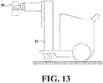
- FIG. 13 illustrates a moving-type radiation device of a conventional configuration.
- a radiation source 56 for irradiating radiation and a support column 52 supporting the radiation source 56 and extending in a vertical direction are provided on a hand-truck carriage.
- the support column 52 slidably supports the radiation source 56.
- the radiation source 56 is configured to be moved in the vertical direction while being supported by the support column 52.
- Such a device has electric assist, and is devised so that the operator can move easily without applying a strong force by hands.
- Such a moving-type radiation device can be moved to a subject's room. By using this device, it becomes possible to perform radiation imaging of the subject without moving the subject as much as possible.
- FIG. 14 schematically illustrates a mechanism for realizing the movements of the radiation source 56 in the vertical direction.
- the left side of FIG. 14 illustrates a typical mechanism of this device which uses a counter weight W having the same weight as the radiation source 56. That is, the device on the left side of FIG. 14 is provided with a wire having one end connected to the radiation source 56 and the other end connected to the counter weight W, and the wire is held by the pulley.
- the radiation source 56 and the counter weight W are related by a well bucket type mechanism.
- the load applied to one end side of the wire is equal to the load applied to the other end side thereof. Therefore, the radiation source 56 and the counter weight W are balanced with each other, and therefore they do not move by themselves. Then, when a force is applied to the radiation source 56, the radiation source 56 easily moves up and down.
- the radiation source 56 has a considerable weight.
- the mechanism on the left side of FIG. 14 requires a counter weight W of the same weight as the radiation source 56. Therefore, when the radiation source 56 is installed on the device, the device increases in weight by the weight of the radiation source 56. Therefore, the moving-type radiation imaging device adopting this mechanism becomes considerably heavy. When the moving-type radiation imaging device is heavy, it is difficult to move it.
- FIG. 14 illustrates this new mechanism.
- This mechanism has a configuration in which the counter weight W on the left side of FIG. 14 is replaced with a tension spring. By removing the counter weight W, the weight of the device can be reduced by an amount equivalent to the weight of the radiation source 56.
- the force transmitted by the radiation source 56 to the pulley is balanced with the tensile force of the tension spring. Therefore, the radiation source 56 and the tensile force of the spring are balanced with each other and radiation source 56 does not move by itself. Then, when a force is applied to the radiation source 56, the radiation source 56 easily moves up and down.
- the tension spring has a property that the tensile force changes when the elongation of the spring changes. Therefore, in order to constantly balance the load of the radiation source 56 and the tensile force of the spring, some ingenuity is required.
- the pulley on the right side of FIG. 14 is a combination of a spiral winding drum and a cylindrical winding drum.
- the spiral winding drum denotes a fixed pulley having a round shaft whose radius changes according to the rotation angle.
- a spiral of Archimedes can be exemplified, but it is not always necessary to use a spiral of Archimedes.
- the tension spring stretches, the tensile force increases, but the radius of the spiral decreases by that amount.
- Patent Document 1 Japanese Unexamined Patent Application Publication No. 2004-033415
- the moving-type radiation device of the conventional configuration has the following problems.
- the moving-type radiation device of the conventional configuration is inadequate in terms of safety.
- the tension spring described on the right side of FIG. 14 has a possibility of being severed due to aged deterioration, etc. It is not easy to prevent this severing of the spring.
- the left side of FIG. 15 shows a state in which the tension spring is severed. As the aged deterioration progresses, the tension spring may be severed suddenly, resulting in a state in which the front and back portions are divided as shown on the right side of FIG. 15 . As a result, the power to control the falling of the radiation source 56 disappears, and therefore the radiation source 56 slides down vertically downward.
- the conventional configuration has been devised so that safety can be secured even if the radiation source 56 which is a load object falls. That is, in the conventional configuration, a safety mechanism for preventing falling of the radiation source 56 is provided separately. Therefore, even if the tension spring is severed, it is practically prevented that the radiation source 56 falls as it is and leads to an accident.
- a safety mechanism is not always fully operational. It is also difficult to completely eliminate the time from the severing of the tension spring to the operation of the safety device. Even if a safety mechanism is equipped, if the tension spring is severed, the radiation source 56 will fall to a certain extent. Such circumstances are undesirable from the viewpoint of safety of the device.
- the present invention has been made in view of the above-described circumstances, and its object is to provide a highly safe moving-type radiation device.
- the present invention has the following configuration to solve the above-mentioned problems.
- the moving-type radiation device includes:
- the present invention it is possible to provide a highly safe moving-type radiation device.
- a tension spring when a spring is severed, the fragments will separate from each other permanently. This becomes a cause of falling of the radiation source. Therefore, the present invention uses a compression spring instead of a tension spring.
- the spring mechanism of the present invention even if the compression spring is severed, the fragments of the compression spring can only move from the tip seat to the junction spring seat. Such a situation is the same for the compression spring, even if it is severed, the fragments can only move from the end seat to the junction spring seat.
- junction spring seat that links a plurality of compression springs. With this, even in cases where the compression springs are linked in series, the compression springs will not be buckled. That is, the junction spring seat is configured to be guided by the shaft, and does not escape in the lateral direction orthogonal to the extension direction of the spring. The individual compression springs are short enough and they will not be buckled.
- the moving-type radiation device includes:
- the present invention has a configuration which can exert the same effects described above with o single compression spring.
- the intermediate connector is configured to be guided by the shaft, and does not escape in the lateral direction orthogonal to the extending direction of the spring.
- Each part of the compression spring divided by the intermediate connector is sufficiently short and it will not be buckled.
- a tip spring seat connected to a spring closer to the support column inner pulley among the springs constituting the spring mechanism and configured to guide the shaft.
- the tip spring seat be provided with a self-aligning mechanism.
- the tip spring seat can guide the inclined shaft smoothly.
- an intermediate member wire having one end connected to the radiation source and the other end connected to the support column or a base on which the support column is installed and an intermediate member pulley configured to support the intermediate member wire and serve as a fixed pulley for the intermediate member.
- the present invention is an example more concretely showing the movement of the intermediate member.
- the present invention can be carried out by incorporating it into the mechanism of the conventional configuration.
- the intermediate member wire be multiplexed.
- the support column inner wire be multiplexed.
- a sensor configured to sense severing of the support column inner wire.
- the present invention it is possible to provide a highly safe moving-type radiation device.
- a compression spring instead of the spring mechanism of the present invention.
- the spring mechanism of the present invention even if a shaft is about to move largely in accordance with severing of a spring, fragments of the spring, which has become stuck each other and immovable, interfere and prevent the movement of the shaft.
- a junction spring seat that links a plurality of compression springs. With this, even in cases where the compression springs are linked in series, the compression springs will not be buckled.
- the device according to the present invention is a radiation device capable of moving to a patient's room by traveling a corridor of a hospital. By combining this device and a radiation detector, it is possible to capture a radiographic image of a subject even in a patient's room.
- the X-ray corresponds to the "radiation" of the present invention.
- FIG. 1 shows an overall configuration of a moving-type X-ray device according to the present invention.
- the device according to the present invention is provided with a chassis 1 at the base portion of the device.
- the chassis 1 has a base 1c provided with two front wheels 1a and two rear wheels 1b.
- the chassis 1 is mounting other parts constituting the device.
- the chassis 1 is configured to support a support column 2.
- a main body B is mounted on the chassis 1.
- the main body B is provided with a power supply device, a battery, an operation panel, a holder for housing a radiation detector, and the like.
- the main body B is provided with a grip G which an operator grasps when driving the device. It is configured such that when an operator applies a force to the grip G, an assist function provided in the chassis 1 works to assist the force given by the operator. With this, the operator can lightly move the device.
- the support column 2 is a member extending in the vertical direction, and the inside is hollow.
- This support column 2 is rotatable about the axis extending in the vertical direction. This support column 2 can be rotated manually.
- This support column 2 supports the X-ray tube 6 described later in an upwardly and downwardly movable manner and extends in the vertical direction, and the inside is hollow.
- the intermediate member 3 is a vertically elongated member provided so as to extend the support column 2.
- the support column 2 supports the intermediate member 3 in an upwardly and downwardly movable manner.
- the support column 2 is provided with a groove extending in the vertical direction configured to receive the intermediate member 3, and the intermediate member 3 can move in the vertical direction along this groove.
- the intermediate member 3 is provided at a position between the X-ray tube 6 and the support column 2 and moves upward and downward in accordance with the upward and downward movements of the X-ray tube 6.
- the tip support column 4 is an L-shaped member provided so as to further extend the intermediate member 3.
- the intermediate member 3 supports the tip support column 4 so as to move upward and downward.
- the tip support column 4 has two arms orthogonal to each other, one arm extending in the vertical direction and the other arm extending in the horizontal direction.
- the intermediate member 3 is provided with a groove extending in the vertical direction configured to receive the vertical direction arm possessed by the tip support column 4, and the tip support column 4 can move in the vertical direction along this groove.
- Lateral support columns 5a and 5b are horizontally elongated members extending in the horizontal direction.
- a horizontal arm possessed by the tip support column 4, the lateral support column 5a, and the lateral support column 5b are telescopically expandable and contractible.
- the left side of FIG. 2 shows the state in which the expansion structure is fully extended.
- the right side of FIG. 2 shows the state in which the expansion structure is fully contracted. This expansion/contraction mechanism can be manually operated.
- the X-ray tube 6 is a device for generating X-rays.
- the X-ray tube 6 is a load object and has a considerable weight.
- the X-ray tube 6 is supported by a lateral support column 5b, and the support column 2, the intermediate member 3, the tip support column 4, and the lateral support columns 5a and 5b are configured to convey the load of the X-ray tube 6 to the chassis 1.
- the circuit related to the control of the X-ray tube 6 is housed in the main body B. Further, the X-ray tube 6 is provided with a collimator 7 for restricting the spread of X-rays. This collimator 7 moves following the movements of the X-ray tube 6.
- the X-ray tube 6 irradiates X-rays.
- FIG. 3 illustrates the upward and downward movements of the tip support column 4.
- the left side of FIG. 3 illustrates the state in which the tip support column 4 is moved to the upper most position
- the right side of FIG. 3 illustrates the state in which the tip support column 4 is moved to the lower most position.
- the intermediate member 3 moves in conjunction with this. That is, it is configured such that when the tip support column 4 is moved in one direction by a certain movement amount, the intermediate member 3 is moved in the same direction by half of the movement amount.
- the device of the present invention is configured such that the vertical movements of the X-ray tube 6 are served by the mechanism composed of the support column 2, the intermediate member 3 and the tip support column 4 and that the lateral movements of the X-ray tube 6 are served by the mechanism composed of the tip support column 4, the lateral support column 5a, and the lateral support column 5b.
- the rotational movements of the X-ray tube 6 are served by the support column 2.
- the support column 2 rotates with respect to the chassis 1.
- the intermediate member 3, the tip support column 4, the lateral support columns 5a and 5b, and the X-ray tube 6 rotate so as to follow the support column 2 while keeping the positional relationship with the support column 2.
- the characteristic feature is a mechanism which realizes the vertical movements of the X-ray tube 6.
- FIG. 4 explains this mechanism.
- a fixing tool for fixing the tip of a wire is provided to the tip support column 4 and the rotary base 1d mounted on the chassis.
- an intermediate member wire 23 is provided to the tip support column 4 and the rotary base 1d mounted on the chassis. That is, one end of the intermediate member wire 23 is fixed to the fixing tool of the tip support column 4, and the other end thereof is fixed to the fixing tool of the rotary base 1d.
- the intermediate member wire 23 is retained in a state of being wrapped around the intermediate member pulley 15 provided in the intermediate member 3 so as to be in contact with the upper side of the intermediate member pulley 15.
- the intermediate member pulley 15 is a fixed pulley for the intermediate member 3.
- the mechanism related to the intermediate member wire 23 will be briefly described. It is assumed that the intermediate member 3 in the state of FIG. 4 moves upward. In this case, looking at the movement of the intermediate member wire 23 with reference to the intermediate member pulley 15, the intermediate member wire 23 is wound up on the rotary base 1d side. Then, the intermediate member wire 23 between the intermediate member pulley 15 and the tip support column 4 becomes shorter, and the tip support column 4 rises accordingly. Further, it is assumed that the intermediate member 3 in the state of FIG. 4 moves downward. In this case, looking at the movement of the intermediate member wire 23 with reference to the intermediate member pulley 15, the intermediate member wire 23 is wound up on the tip support column 4 side.
- the intermediate member wire 23 between the intermediate member pulley 15 and the tip support column 4 becomes longer, and the tip support column 4 descends accordingly.
- the intermediate member wire 23 is wound up twice the length, so the moving distance of the tip support column 4 becomes also twice the moving distance of the intermediate member 3.
- the support column 2 is hollow, and is provided with various mechanisms in the inner hollow space of the support column 2. On the inner surface corresponding to the ceiling of the internal space of the support column, there is provided a fixing tool for fixing the tip of a wire. Similarly, the intermediate member 3 is also provided with a fixing tool.
- a winding pulley 14a and a spiral pulley 14b are provided in the support column. These pulleys 14a and 14b are fixed pulleys for the support column 2 and share the rotation shaft.
- the winding pulley 14a has a cylindrical shape, and is provided with a coiled groove.
- the spiral pulley 14b is a pulley having a wheel shaft whose radius ratio is variable, and has a tapered shape.
- the winding pulley 14a and the spiral pulley 14b are each provided with a fixing tool for fixing a tip of a wire.
- winding pulley wire 12a In the winding pulley wire 12a, one end thereof is fixed to the fixing tool of the intermediate member 3 and the other end thereof is fixed to the fixing tool of the winding pulley 14a.
- the winding pulley wire 12a is held in the form wrapped around the winding pulley 14a. Therefore, the winding pulley wire 12a extends from the winding pulley wire 12a as a starting point and is held so as to unwind to the lower side of the winding pulley wire 12a.
- the support column inner wire 12b has one end fixed to the fixing tool of the spiral pulley 14b and the other end fixed to the fixing tool provided in the support column 2.
- the support column inner wire 12b is held in the form wound around the spiral pulley 14b. Therefore, the support column inner wire 12b extends from the spiral pulley 14b as a starting point and is held so as to unwind toward the lower side of the spiral pulley 14b.
- a relay pulley 13a which is a fixed pulley for the support column 2 is provided inside the support column 2, between the support column inner pulley 14 and the fixing tool provided on the inner surface of the support column 2, a relay pulley 13a which is a fixed pulley for the support column 2 is provided.
- the relay pulley 13a supports the support column inner wire 12b.
- the support column inner wire 12b is held in a state of being wound on the relay pulley 13a so as to be in contact with the upper side of the relay pulley 13a.
- the relay pulley 13a is provided on the other end side of the support column inner wire 12b when viewed from the support column inner pulley 14 and is configured to support the support column inner wire 12b and serves as a fixed pulley for the support column 2 provided in the support column 2.
- a movable pulley 13b On each side of the relay pulley 13a, a movable pulley 13b is provided which moves with respect to the relay pulley 13a.
- the support column inner wire 12b is held in a state of being wound on the two movable pulleys 13b so as to be in contact with the lower side of the movable pulley 13b.
- the support column inner wire 12b is wound on the support column inner pulley 14, the movable pulley 13b, the relay pulley 13a, and the movable pulley 13b one after another, and extends to the end point of the fixing tool provided on the inner surface of the support column 2.
- FIG. 4 The inside of the support column 2 shown in FIG. 4 is illustrated so that the transmission of power can be easy to understand. If the internal mechanism of the support column 2 is configured as shown in FIG. 4 , the diameter of the support column 2 has to be made considerably large.
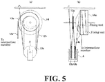
- FIG. 5 shows an arrangement example in which the same mechanism as in FIG. 4 is arranged in a more compact manner. According to such an arrangement example, it is possible to reduce the diameter of the support column 2.
- the left side of FIG. 5 shows the arrangement example as viewed from the rotation axis direction of the support column inner pulley 14.
- the rotation axis of the support column inner pulley 14 is depicted so as to be orthogonal to the rotation axis of the relay pulley 13a, but the rotation axes of the support column inner pulley 14 and the relay pulley 13a may be made to coincide with each other as shown on the left side of FIG. 5 .
- the movable pulley 13b is arranged in a direction orthogonal to the rotation axis, but both the rotation axes may be arranged so as to coincide with each other as shown on the left side of FIG. 5 .
- the right side of FIG. 5 shows the arrangement example as viewed from the direction orthogonal to the rotation axis of the support column inner pulley 14.
- the spring mechanism which is a characteristic part of the present invention will be described.
- the spring mechanism generates a force to unwind the support column inner wire 12b from the support column inner pulley 14 by pulling the support column inner wire 12b downward via the two movable pulleys 13b. This force detains the downward movement of the intermediate member 3.
- the spring mechanism is a configuration that gives a tensile force to the support column inner wire 12b, and is provided in the support column 2.
- the spring mechanism is provided with two coiled compression springs 8a and 8b arranged in series in the vertical direction. As shown on the right side of FIG. 4 , in the compression springs 8a and 8b, it is preferable that the ratio of the diameter to the length be about 1: 4 or less. This is because if the compression spring 8a, 8b is longer than this, buckling is likely to occur.
- the compression spring is a spring which, unlike the tension spring, gives a repulsive force when compressed to a certain object. As a familiar compression spring, there is a spring for holding a negative electrode provided in a dry battery holder.
- the spring mechanism links a plurality of compression springs 8a and 8b arranged in series in the vertical direction, and the junction spring seat 9 links the compression springs.
- the two compression springs 8a and 8b are provided so as to be in contact with each other in the vertical direction with the same central axis.
- a disk-shaped junction spring seat 9 is provided at a position between the two compression springs 8a and 8b.
- the structure of this junction spring seat 9 will be described.
- FIG. 6 is a conceptual diagram for more easily explaining the structure of the spring mechanism. In FIG. 6 , the cross-section of the compression spring 8a and its peripheral components is shown so that the inside of the compression spring 8a can be easily understood. To the junction spring seat 9, the end portions of different compression springs 8a and 8b are fitted from the upper and lower sides.
- the junction spring seat 9 is provided with cylindrically-shaped projections for fitting compression springs 8a and 8b on the upper and lower sides, the lower end of the compression spring 8a positioned at the lower side of both end of the compression spring 8a and the upper end of the compression spring 8b positioned at the upper end thereof fit in the corresponding projections, respectively.
- the compression springs 8a and 8b are connected to the junction spring seat 9.
- the junction spring seat 9 is provided with a through-hole extending in the vertical direction. Inside the through-hole, a shaft 10, which will be described later, is disposed.
- the compression springs 8a and 8b and the junction spring seat 9 linking them function like a single compression spring. So, the compression springs 8a and 8b and the junction spring seat 9 will be referred to as a spring unit.
- a spring unit At the lower portion of the spring unit, a disc-shaped end spring seat 11 is provided.
- a cylindrically-shaped projection for fitting the compression spring 8b is provided at the top, and the lower end of both ends of the spring unit is connected to the end spring seat 11 by being fitted on this projection .
- the end spring seat 11 is provided with a through-hole extending in the vertical direction. Inside the through-hole, a shaft 10, which will be described later, is disposed.
- a disk-shaped tip spring seat 21 is provided at the upper portion of the spring unit.
- a cylindrically-shaped projection for fitting the compression spring 8a is provided at the lower portion, and the tip end of both ends of the spring unit is connected to the tip spring seat 21 by being fitted on this projection .
- the tip spring seat 21 is provided with a through-hole extending in the vertical direction. Inside the through-hole, a shaft 10, which will be described later, is disposed.
- the shaft 10 is a vertically extended member provided so as to pass through insides of the plurality of compression springs 8a and 8b, the shaft being connected to one end of the spring unit configured by connecting the compression springs and configured to support the junction spring seat 9 in an upwardly and downwardly movable manner.
- the tip spring seat 21 is configured to guide the shaft 10.
- the tip spring seat 21 is configured to be connected to a spring closer to the support column inner pulley 14 among the springs constituting the spring mechanism and configured to guide the shaft 10.
- a partition wall 22 for supporting the tip spring seat 21 is provided in the hollow portion of the support column 2.
- the partition wall 22 is provided so as to divide the hollow portion of the support column into an upper part and a lower part, and also is provided with a through-hole extending in the vertical direction for passing through the shaft 10.
- the partition wall 22 is fixed to the inner wall of the support column 2 and prevents the tip spring seat 21 from moving upward in the support column 2.
- the partition wall 22 corresponds to the "unit fixing member" of the present invention.
- the partition wall 22 fixes the other end of the spring unit to the support column 2.
- the shaft 10 is a rod-shaped structure extending in the vertical direction from the lower end of the spring unit as a starting point, passing through the inside of the coiled spring unit, and protruding from the upper end of the spring unit, and extends in the vertical direction.
- a screw thread is cut and the nut is screwed into the screw thread.
- This nut is located on the lower side of the end spring seat 11 and is supported by the shaft 10. The nut prevents the falling of the end spring seat 11 positioned at the top of the nut. This nut prevents the decomposition of the spring unit.
- the spring unit is extendable and contractible in the vertical direction.
- the shaft 10, the end spring seat 11 and the junction spring seat 9 constituting the spring unit move upward and downward in the vertical direction so as to follow the expansion/contraction.
- the movement amount of the end spring seat 11 is larger than the movement amount of the junction spring seat 9. This is because the displacement amount of the spring increases as it goes to the end.
- the shaft 10 and the end spring seat 11 are fixed, even if the spring unit is extended or contracts, there is no change in the relative position.
- the tip spring seat 21 is restrained by the partition wall 22 and therefore does not move, but the relative position between the tip spring seat 21 and the shaft 10 changes.
- a bearing (not shown) is provided for the purpose of smoothly guiding the shaft 10.
- an arm A supporting the above-described movable pulleys 13b is provided in a fixed state.
- the arm A has a U-shape.
- a movable pulley 13b is provided at each of the tips of the arm A.
- the arm A is fixed to the shaft 10.
- the movable pulleys 13b are supported by the arm A and disposed on both sides of the relay pulley 13a.
- the respective movable pulleys 13b are wound by the support column inner wire 12b.
- the spring mechanism in this specification means a composite of the arm A, the compression springs 8a and 8b, the junction spring seat 9, the shaft 10, the end spring seat 11, the tip spring seat 21, and the movable pulley 13b.
- the force that the spring mechanism of the present invention imparts to the support column inner wire 12b will be described. Since the spring unit is composed of the compression springs, it gives a force to keep the tip spring seat 21 and the end spring seat 11 away from each other. The tip spring seat 21 will not move inside the support column 2, so that the spring unit will give a descending force to the shaft 10. This force is transmitted to the movable pulley 13b located at the tip of the arm A. Thus, the support column inner wire 12b is given the force to push the wire down. That is, the force that extends the spring unit generates a force occurred at the movable pulleys 13b to push down the support column inner wire 12b.
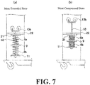
- FIG. 7 shows the state of extension and contraction of the spring unit.
- the left side of FIG. 7 shows the state in which the spring unit is most extended.
- the X-ray tube 6 is most moved upward, and does not move further upward from this position.
- the compression springs 8a and 8b constituting the spring unit still have the power to extend. Therefore, the force of moving the tip spring seat 21 and the end spring seat 11 away from each other is maintained although it is weak.
- FIG. 7 shows the state in which the spring unit is most compressed.
- the X-ray tube 6 is most moved downward, and does not move further downward from this position.
- the compression springs 8a and 8b constituting the spring unit is most compressed. Therefore, the force for keeping the tip spring seat 21 and the end spring seat 11 away from each other becomes the strongest state.
- FIG. 8 shows the case in which the compression spring 8a is severed due to the aged deterioration or the like. Even if the compression spring 8a is severed, the respective fragments try to stretch. Then, the fragments get caught each other and prevent the respective extensions.
- the difference between before and after the compression spring 8a is severed is that the compression spring 8a in a coil form has been shortened by one pitch. Therefore, when the spring is severed, the spring becomes shorter by one pitch, so that the X-ray tube 6 drops a distance corresponding to it, but the situation of falling indefinitely does not occur.
- the compression spring when used instead of the counter weight described on the left side of FIG. 14 , it helps to maintain the safety of the device, but there are difficult problems to solve.
- the compression spring is difficult to secure the stroke.
- the tension spring is suitable for a mechanism having a long stroke. If it is desired to lengthen the stroke, it is enough to lengthen the spring. However, a compression spring cannot earn a stroke with the same principle.
- a compression spring has its own problem of buckling.
- a compression spring has a characteristic that it becomes easier to bend as it gets longer.
- a compression spring is used in such a way that a pressure is applied from both sides of the spring, but as the spring becomes longer, the middle of the spring is likely to escape in a direction orthogonal to the extension direction of the spring. As a result, the spring will bend and will not fulfill its original function.
- junction spring seat 9 is configured to be guided by the shaft 10, and does not escape in the lateral direction orthogonal to the extension direction of the spring.
- the compression springs 8a and 8b are supported by the junction spring seat 9 and cannot escape in the lateral direction.
- the individual compression springs 8a and 8b are short enough that they will not be buckled. As a result, the spring will not bend and exert its original function.
- the present invention is not limited to the aforementioned configuration, and may be modified as follows.
- a self-aligning mechanism may be provided in the tip spring seat 21 itself. With this configuration, even if the shaft 10 is inclined, a large force from the shaft 10 is not applied to the covering member 21b and therefore no friction occurs between the covering member 21b and the shaft 10, so that the movements of the shaft 10 become smooth.
- the present invention is suitably applicable in the medial field.
Landscapes
- Health & Medical Sciences (AREA)
- Life Sciences & Earth Sciences (AREA)
- Medical Informatics (AREA)
- Engineering & Computer Science (AREA)
- Radiology & Medical Imaging (AREA)
- Biomedical Technology (AREA)
- Biophysics (AREA)
- Nuclear Medicine, Radiotherapy & Molecular Imaging (AREA)
- Optics & Photonics (AREA)
- Pathology (AREA)
- Physics & Mathematics (AREA)
- High Energy & Nuclear Physics (AREA)
- Heart & Thoracic Surgery (AREA)
- Molecular Biology (AREA)
- Surgery (AREA)
- Animal Behavior & Ethology (AREA)
- General Health & Medical Sciences (AREA)
- Public Health (AREA)
- Veterinary Medicine (AREA)
- Apparatus For Radiation Diagnosis (AREA)
Abstract
Description
- The present invention relates to a moving-type radiation device used for the rounds for patients, and more particularly to a moving-type radiation imaging device equipped with a mechanism for adjusting height of a radiation source.
-
FIG. 13 illustrates a moving-type radiation device of a conventional configuration. In this device, aradiation source 56 for irradiating radiation and asupport column 52 supporting theradiation source 56 and extending in a vertical direction are provided on a hand-truck carriage. Thesupport column 52 slidably supports theradiation source 56. Theradiation source 56 is configured to be moved in the vertical direction while being supported by thesupport column 52. Such a device has electric assist, and is devised so that the operator can move easily without applying a strong force by hands. - Such a moving-type radiation device can be moved to a subject's room. By using this device, it becomes possible to perform radiation imaging of the subject without moving the subject as much as possible.
-
FIG. 14 schematically illustrates a mechanism for realizing the movements of theradiation source 56 in the vertical direction. The left side ofFIG. 14 illustrates a typical mechanism of this device which uses a counter weight W having the same weight as theradiation source 56. That is, the device on the left side ofFIG. 14 is provided with a wire having one end connected to theradiation source 56 and the other end connected to the counter weight W, and the wire is held by the pulley. In this way, theradiation source 56 and the counter weight W are related by a well bucket type mechanism. The load applied to one end side of the wire is equal to the load applied to the other end side thereof. Therefore, theradiation source 56 and the counter weight W are balanced with each other, and therefore they do not move by themselves. Then, when a force is applied to theradiation source 56, theradiation source 56 easily moves up and down. - The
radiation source 56 has a considerable weight. The mechanism on the left side ofFIG. 14 requires a counter weight W of the same weight as theradiation source 56. Therefore, when theradiation source 56 is installed on the device, the device increases in weight by the weight of theradiation source 56. Therefore, the moving-type radiation imaging device adopting this mechanism becomes considerably heavy. When the moving-type radiation imaging device is heavy, it is difficult to move it. - Therefore, a mechanism capable of reducing the weight of the moving-type radiation imaging device has been proposed (see Patent Document 1). The right side of
FIG. 14 illustrates this new mechanism. This mechanism has a configuration in which the counter weight W on the left side ofFIG. 14 is replaced with a tension spring. By removing the counter weight W, the weight of the device can be reduced by an amount equivalent to the weight of theradiation source 56. - In the mechanism shown on the right side of
FIG. 14 , the force transmitted by theradiation source 56 to the pulley is balanced with the tensile force of the tension spring. Therefore, theradiation source 56 and the tensile force of the spring are balanced with each other andradiation source 56 does not move by itself. Then, when a force is applied to theradiation source 56, theradiation source 56 easily moves up and down. - The tension spring has a property that the tensile force changes when the elongation of the spring changes. Therefore, in order to constantly balance the load of the
radiation source 56 and the tensile force of the spring, some ingenuity is required. The pulley on the right side ofFIG. 14 is a combination of a spiral winding drum and a cylindrical winding drum. In this case, the spiral winding drum denotes a fixed pulley having a round shaft whose radius changes according to the rotation angle. As the spiral, specifically, a spiral of Archimedes can be exemplified, but it is not always necessary to use a spiral of Archimedes. As the tension spring stretches, the tensile force increases, but the radius of the spiral decreases by that amount. To the contrary, when the tension spring contracts and the tensile force weakens, the radius of the spiral increases by that amount. As a result, the same torque is always applied to the pulley. Therefore, theradiation source 56 is moved up and down in the same behavior as when the counter weight W is used. - Patent Document 1: Japanese Unexamined Patent Application Publication No.
2004-033415 - However, the moving-type radiation device of the conventional configuration has the following problems.
- That is, the moving-type radiation device of the conventional configuration is inadequate in terms of safety.
- The tension spring described on the right side of
FIG. 14 has a possibility of being severed due to aged deterioration, etc. It is not easy to prevent this severing of the spring. The left side ofFIG. 15 shows a state in which the tension spring is severed. As the aged deterioration progresses, the tension spring may be severed suddenly, resulting in a state in which the front and back portions are divided as shown on the right side ofFIG. 15 . As a result, the power to control the falling of theradiation source 56 disappears, and therefore theradiation source 56 slides down vertically downward. - Because of this situation, the conventional configuration has been devised so that safety can be secured even if the
radiation source 56 which is a load object falls. That is, in the conventional configuration, a safety mechanism for preventing falling of theradiation source 56 is provided separately. Therefore, even if the tension spring is severed, it is practically prevented that theradiation source 56 falls as it is and leads to an accident. - However, a safety mechanism is not always fully operational. It is also difficult to completely eliminate the time from the severing of the tension spring to the operation of the safety device. Even if a safety mechanism is equipped, if the tension spring is severed, the
radiation source 56 will fall to a certain extent. Such circumstances are undesirable from the viewpoint of safety of the device. - The present invention has been made in view of the above-described circumstances, and its object is to provide a highly safe moving-type radiation device.
- The present invention has the following configuration to solve the above-mentioned problems.
- That is, the moving-type radiation device according to the present invention includes:
- a radiation source configured to irradiate radiation;
- a support column configured to support the radiation source in an upwardly and downwardly movable manner and extending in a vertical direction;
- an intermediate member provided at a position between the radiation source and the support column so as to be upwardly and downwardly movable in accordance with upward and downward movements of the radiation source;
- a support column inner wire having one end connected to the intermediate member and the other end connected to an inside of the support column;
- a support column inner pulley configured to support the support column inner wire and serve as a fixed pulley for the support column provided in the support column;
- a relay pulley provided on the other end side of the support column inner wire when viewed from the support column inner pulley and configured to support the support column inner wire and serve as a fixed pulley for the support column provided in the support column;
- a spring mechanism configured to give a tensile force to the support column inner wire and provided in the support column,
- wherein the spring mechanism includes:
- (A) a plurality of compression springs arranged in series in a vertical direction;
- (B1) a junction spring seat configured to connect the compression springs; and
- (C1) a vertically extended shaft provided so as to pass through an inside of the plurality of compression springs, the shaft being connected to one end of a spring unit configured by connecting the compression springs and configured to support the junction spring seat in an upwardly and downwardly movable manner.
- [Functions and Effects] According to the present invention, it is possible to provide a highly safe moving-type radiation device. In the case of a conventional configuration using a tension spring, when a spring is severed, the fragments will separate from each other permanently. This becomes a cause of falling of the radiation source. Therefore, the present invention uses a compression spring instead of a tension spring. According to the spring mechanism of the present invention, even if the compression spring is severed, the fragments of the compression spring can only move from the tip seat to the junction spring seat. Such a situation is the same for the compression spring, even if it is severed, the fragments can only move from the end seat to the junction spring seat. This is because even if a shaft is about to move largely in accordance with the severing of the spring, fragments of the spring, which has become stuck each other and immovable, interfere and prevent the movement of the shaft. With this principle, the radiation source will not fall even if the spring is severed.
- However, there is a characteristic feature that as the compression spring gets longer, it tends to become more bedable. The compression spring is difficult to secure a stroke. So, what has been devised in the present invention is a junction spring seat that links a plurality of compression springs. With this, even in cases where the compression springs are linked in series, the compression springs will not be buckled. That is, the junction spring seat is configured to be guided by the shaft, and does not escape in the lateral direction orthogonal to the extension direction of the spring. The individual compression springs are short enough and they will not be buckled.
- Further, the moving-type radiation device according to the present invention includes:
- a radiation source configured to irradiate radiation;
- a support column configured to support the radiation source in an upwardly and downwardly movable manner and extending in a vertical direction;
- an intermediate member provided at a position between the radiation source and the support column so as to be upwardly and downwardly movable in accordance with upward and downward movements of the radiation source;
- a support column inner wire having one end connected to the intermediate member and the other end connected to an inside of the support column;
- a support column inner pulley configured to support the support column inner wire and serve as a fixed pulley for the support column provided in the support column;
- a relay pulley provided on the other end side of the support column inner wire when viewed from the support column inner pulley and configured to support the support column inner wire and serve as a fixed pulley for the support column provided in the support column; and a spring mechanism configured to give a tensile force to the support column inner wire and provided in the support column,
- wherein the spring mechanism includes:
- (A) a compression spring arranged in a vertical direction;
- (B2) an intermediate connector fixed in a middle of the compression spring; and
- (C2) a vertically extended shaft provided so as to pass through an inside of the compression spring, the shaft being connected to one end of the compression spring and configured to support the intermediate connector in an upwardly and downwardly movable manner.
- [Functions and Effects] The present invention has a configuration which can exert the same effects described above with o single compression spring. The intermediate connector is configured to be guided by the shaft, and does not escape in the lateral direction orthogonal to the extending direction of the spring. Each part of the compression spring divided by the intermediate connector is sufficiently short and it will not be buckled.
- Further, in the above-described moving-type radiation device, it is preferable to further include a tip spring seat connected to a spring closer to the support column inner pulley among the springs constituting the spring mechanism and configured to guide the shaft.
- [Functions and Effects] According to the above-described configuration, it is possible to provide a configuration in which the shaft is assuredly guided by the tip spring seat.
- Further, in the above-described moving-type radiation device, it is preferable that the tip spring seat be provided with a self-aligning mechanism.
- [Functions and Effects] According to the above-described configuration, the tip spring seat can guide the inclined shaft smoothly.
- Further, in the above-described moving-type radiation imaging device, it is more preferable to further include an intermediate member wire having one end connected to the radiation source and the other end connected to the support column or a base on which the support column is installed and an intermediate member pulley configured to support the intermediate member wire and serve as a fixed pulley for the intermediate member.
- [Functions and Effects] The present invention is an example more concretely showing the movement of the intermediate member. The present invention can be carried out by incorporating it into the mechanism of the conventional configuration.
- Further, in the above-described moving-type radiation device, it is more preferable that the intermediate member wire be multiplexed.
- [Functions and Effects] The above-described configuration represents a more desirable configuration of the present invention. When the intermediate member wire is multiplexed, a more safe moving-type radiation device can be provided.
- In the above-described moving-type radiation device, it is more preferable that the support column inner wire be multiplexed.
- [Functions and Effects] The above-described configuration represents a more desirable configuration of the present invention. When the support column inner wire is multiplexed, a more safe moving-type radiation device can be provided.
- In the above-described moving-type radiation device, it is more preferable to further include a sensor configured to sense severing of the support column inner wire.
- [Functions and Effects] The above-described configuration represents a more desirable configuration of the present invention. When a sensor for sensing the severing of the support column inner wire, a more safe moving-type radiation device can be provided.
- According to the present invention, it is possible to provide a highly safe moving-type radiation device. In the case of a conventional configuration using a tension spring, if the spring is severed, the fragments will separate from each other permanently. Therefore, the present invention uses a compression spring instead. According to the spring mechanism of the present invention, even if a shaft is about to move largely in accordance with severing of a spring, fragments of the spring, which has become stuck each other and immovable, interfere and prevent the movement of the shaft. So, what has been devised in the present invention is a junction spring seat that links a plurality of compression springs. With this, even in cases where the compression springs are linked in series, the compression springs will not be buckled.
-
-
FIG. 1 is a plan view explaining an overall configuration of a moving-type X-ray device according to Example 1. -
FIG. 2 is a schematic diagram explaining a lateral movement of an X-ray tube according to Example 1. -
FIG. 3 is a schematic diagram explaining a vertical movement of an X-ray tube according to Example 1. -
FIG. 4 is a cross-sectional view explaining a mechanism related to the vertical movement of the X-ray tube according to Example 1. -
FIG. 5 is a schematic diagram showing a specific example of a mechanism according to Example 1. -
FIG. 6 is a cross-sectional view explaining a spring mechanism according to Example 1. -
FIG. 7 is a cross-sectional view explaining an extension and compression of a spring unit according to Example 1. -
FIG. 8 is a cross-sectional view explaining effects of the configuration according to Example 1. -
FIG. 9 is a cross-sectional view explaining one modified example of the present invention. -
FIG. 10 is a cross-sectional view explaining one modified example of the present invention. -
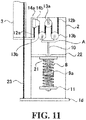
FIG. 11 is a cross-sectional view explaining one modified example of the present invention. -
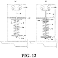
FIG. 12 is a cross-sectional view explaining one modified example of the present invention. -
FIG. 13 is a schematic diagram explaining a configuration of a moving-type radiation device of a conventional configuration. -
FIG. 14 is a schematic diagram explaining a configuration of the moving-type radiation device of the conventional configuration. -
FIG. 15 is a schematic diagram explaining the problems of the moving-type radiation device of the conventional configuration. - Next, the moving-type radiation device according to the present invention will be described. The device according to the present invention is a radiation device capable of moving to a patient's room by traveling a corridor of a hospital. By combining this device and a radiation detector, it is possible to capture a radiographic image of a subject even in a patient's room. The X-ray corresponds to the "radiation" of the present invention.
-
FIG. 1 shows an overall configuration of a moving-type X-ray device according to the present invention. The device according to the present invention is provided with achassis 1 at the base portion of the device. Thechassis 1 has a base 1c provided with twofront wheels 1a and tworear wheels 1b. Thechassis 1 is mounting other parts constituting the device. Thechassis 1 is configured to support asupport column 2. - A main body B is mounted on the
chassis 1. The main body B is provided with a power supply device, a battery, an operation panel, a holder for housing a radiation detector, and the like. The main body B is provided with a grip G which an operator grasps when driving the device. It is configured such that when an operator applies a force to the grip G, an assist function provided in thechassis 1 works to assist the force given by the operator. With this, the operator can lightly move the device. - The
support column 2 is a member extending in the vertical direction, and the inside is hollow. Thissupport column 2 is rotatable about the axis extending in the vertical direction. Thissupport column 2 can be rotated manually. Thissupport column 2 supports theX-ray tube 6 described later in an upwardly and downwardly movable manner and extends in the vertical direction, and the inside is hollow. - The
intermediate member 3 is a vertically elongated member provided so as to extend thesupport column 2. Thesupport column 2 supports theintermediate member 3 in an upwardly and downwardly movable manner. Thesupport column 2 is provided with a groove extending in the vertical direction configured to receive theintermediate member 3, and theintermediate member 3 can move in the vertical direction along this groove. Theintermediate member 3 is provided at a position between theX-ray tube 6 and thesupport column 2 and moves upward and downward in accordance with the upward and downward movements of theX-ray tube 6. - The
tip support column 4 is an L-shaped member provided so as to further extend theintermediate member 3. Theintermediate member 3 supports thetip support column 4 so as to move upward and downward. Thetip support column 4 has two arms orthogonal to each other, one arm extending in the vertical direction and the other arm extending in the horizontal direction. Theintermediate member 3 is provided with a groove extending in the vertical direction configured to receive the vertical direction arm possessed by thetip support column 4, and thetip support column 4 can move in the vertical direction along this groove. -
Lateral support columns tip support column 4, thelateral support column 5a, and thelateral support column 5b are telescopically expandable and contractible. The left side ofFIG. 2 shows the state in which the expansion structure is fully extended. The right side ofFIG. 2 shows the state in which the expansion structure is fully contracted. This expansion/contraction mechanism can be manually operated. - The
X-ray tube 6 is a device for generating X-rays. TheX-ray tube 6 is a load object and has a considerable weight. TheX-ray tube 6 is supported by alateral support column 5b, and thesupport column 2, theintermediate member 3, thetip support column 4, and thelateral support columns X-ray tube 6 to thechassis 1. The circuit related to the control of theX-ray tube 6 is housed in the main body B. Further, theX-ray tube 6 is provided with acollimator 7 for restricting the spread of X-rays. Thiscollimator 7 moves following the movements of theX-ray tube 6. TheX-ray tube 6 irradiates X-rays. -
FIG. 3 illustrates the upward and downward movements of thetip support column 4. The left side ofFIG. 3 illustrates the state in which thetip support column 4 is moved to the upper most position, and the right side ofFIG. 3 illustrates the state in which thetip support column 4 is moved to the lower most position. When thetip support column 4 is moved in the vertical direction, theintermediate member 3 moves in conjunction with this. That is, it is configured such that when thetip support column 4 is moved in one direction by a certain movement amount, theintermediate member 3 is moved in the same direction by half of the movement amount. - As described above, according to the device of the present invention, it is configured such that the vertical movements of the
X-ray tube 6 are served by the mechanism composed of thesupport column 2, theintermediate member 3 and thetip support column 4 and that the lateral movements of theX-ray tube 6 are served by the mechanism composed of thetip support column 4, thelateral support column 5a, and thelateral support column 5b. The rotational movements of theX-ray tube 6 are served by thesupport column 2. When a force that rotates theX-ray tube 6 about the vertical axis is applied, thesupport column 2 rotates with respect to thechassis 1. Then, theintermediate member 3, thetip support column 4, thelateral support columns X-ray tube 6 rotate so as to follow thesupport column 2 while keeping the positional relationship with thesupport column 2. - In the present invention, the characteristic feature is a mechanism which realizes the vertical movements of the
X-ray tube 6.FIG. 4 explains this mechanism. To thetip support column 4 and therotary base 1d mounted on the chassis, a fixing tool for fixing the tip of a wire is provided. Between these two fixing tools, anintermediate member wire 23 is provided. That is, one end of theintermediate member wire 23 is fixed to the fixing tool of thetip support column 4, and the other end thereof is fixed to the fixing tool of therotary base 1d. Theintermediate member wire 23 is retained in a state of being wrapped around theintermediate member pulley 15 provided in theintermediate member 3 so as to be in contact with the upper side of theintermediate member pulley 15. Theintermediate member pulley 15 is a fixed pulley for theintermediate member 3. - The mechanism related to the
intermediate member wire 23 will be briefly described. It is assumed that theintermediate member 3 in the state ofFIG. 4 moves upward. In this case, looking at the movement of theintermediate member wire 23 with reference to theintermediate member pulley 15, theintermediate member wire 23 is wound up on therotary base 1d side. Then, theintermediate member wire 23 between theintermediate member pulley 15 and thetip support column 4 becomes shorter, and thetip support column 4 rises accordingly. Further, it is assumed that theintermediate member 3 in the state ofFIG. 4 moves downward. In this case, looking at the movement of theintermediate member wire 23 with reference to theintermediate member pulley 15, theintermediate member wire 23 is wound up on thetip support column 4 side. Then, theintermediate member wire 23 between theintermediate member pulley 15 and thetip support column 4 becomes longer, and thetip support column 4 descends accordingly. When theintermediate member 3 moves by a certain length, theintermediate member wire 23 is wound up twice the length, so the moving distance of thetip support column 4 becomes also twice the moving distance of theintermediate member 3. - The
support column 2 is hollow, and is provided with various mechanisms in the inner hollow space of thesupport column 2. On the inner surface corresponding to the ceiling of the internal space of the support column, there is provided a fixing tool for fixing the tip of a wire. Similarly, theintermediate member 3 is also provided with a fixing tool. - In the support column, a winding
pulley 14a and aspiral pulley 14b are provided. Thesepulleys support column 2 and share the rotation shaft. The windingpulley 14a has a cylindrical shape, and is provided with a coiled groove. On the other hand, thespiral pulley 14b is a pulley having a wheel shaft whose radius ratio is variable, and has a tapered shape. The windingpulley 14a and thespiral pulley 14b are each provided with a fixing tool for fixing a tip of a wire. - In the winding
pulley wire 12a, one end thereof is fixed to the fixing tool of theintermediate member 3 and the other end thereof is fixed to the fixing tool of the windingpulley 14a. The windingpulley wire 12a is held in the form wrapped around the windingpulley 14a. Therefore, the windingpulley wire 12a extends from the windingpulley wire 12a as a starting point and is held so as to unwind to the lower side of the windingpulley wire 12a. - The support column
inner wire 12b has one end fixed to the fixing tool of thespiral pulley 14b and the other end fixed to the fixing tool provided in thesupport column 2. The support columninner wire 12b is held in the form wound around thespiral pulley 14b. Therefore, the support columninner wire 12b extends from thespiral pulley 14b as a starting point and is held so as to unwind toward the lower side of thespiral pulley 14b. - Inside the
support column 2, between the support columninner pulley 14 and the fixing tool provided on the inner surface of thesupport column 2, arelay pulley 13a which is a fixed pulley for thesupport column 2 is provided. Therelay pulley 13a supports the support columninner wire 12b. The support columninner wire 12b is held in a state of being wound on therelay pulley 13a so as to be in contact with the upper side of therelay pulley 13a. Therelay pulley 13a is provided on the other end side of the support columninner wire 12b when viewed from the support columninner pulley 14 and is configured to support the support columninner wire 12b and serves as a fixed pulley for thesupport column 2 provided in thesupport column 2. - On each side of the
relay pulley 13a, amovable pulley 13b is provided which moves with respect to therelay pulley 13a. The support columninner wire 12b is held in a state of being wound on the twomovable pulleys 13b so as to be in contact with the lower side of themovable pulley 13b. - Therefore, starting from the fixing tool of the
intermediate member 3, the support columninner wire 12b is wound on the support columninner pulley 14, themovable pulley 13b, therelay pulley 13a, and themovable pulley 13b one after another, and extends to the end point of the fixing tool provided on the inner surface of thesupport column 2. - The inside of the
support column 2 shown inFIG. 4 is illustrated so that the transmission of power can be easy to understand. If the internal mechanism of thesupport column 2 is configured as shown inFIG. 4 , the diameter of thesupport column 2 has to be made considerably large. On the other hand,FIG. 5 shows an arrangement example in which the same mechanism as inFIG. 4 is arranged in a more compact manner. According to such an arrangement example, it is possible to reduce the diameter of thesupport column 2. - The left side of
FIG. 5 shows the arrangement example as viewed from the rotation axis direction of the support columninner pulley 14. According to the explanation with reference toFIG. 4 , the rotation axis of the support columninner pulley 14 is depicted so as to be orthogonal to the rotation axis of therelay pulley 13a, but the rotation axes of the support columninner pulley 14 and therelay pulley 13a may be made to coincide with each other as shown on the left side ofFIG. 5 . Further, according to the explanation with reference toFIG. 4 , themovable pulley 13b is arranged in a direction orthogonal to the rotation axis, but both the rotation axes may be arranged so as to coincide with each other as shown on the left side ofFIG. 5 . The right side ofFIG. 5 shows the arrangement example as viewed from the direction orthogonal to the rotation axis of the support columninner pulley 14. - Next, the spring mechanism which is a characteristic part of the present invention will be described. The spring mechanism generates a force to unwind the support column
inner wire 12b from the support columninner pulley 14 by pulling the support columninner wire 12b downward via the twomovable pulleys 13b. This force detains the downward movement of theintermediate member 3. The spring mechanism is a configuration that gives a tensile force to the support columninner wire 12b, and is provided in thesupport column 2. - The spring mechanism is provided with two coiled compression springs 8a and 8b arranged in series in the vertical direction. As shown on the right side of
FIG. 4 , in the compression springs 8a and 8b, it is preferable that the ratio of the diameter to the length be about 1: 4 or less. This is because if thecompression spring junction spring seat 9 links the compression springs. - The two
compression springs junction spring seat 9 is provided at a position between the twocompression springs junction spring seat 9 will be described.FIG. 6 is a conceptual diagram for more easily explaining the structure of the spring mechanism. InFIG. 6 , the cross-section of thecompression spring 8a and its peripheral components is shown so that the inside of thecompression spring 8a can be easily understood. To thejunction spring seat 9, the end portions ofdifferent compression springs junction spring seat 9 is provided with cylindrically-shaped projections for fitting compression springs 8a and 8b on the upper and lower sides, the lower end of thecompression spring 8a positioned at the lower side of both end of thecompression spring 8a and the upper end of thecompression spring 8b positioned at the upper end thereof fit in the corresponding projections, respectively. As a result, the compression springs 8a and 8b are connected to thejunction spring seat 9. Further, thejunction spring seat 9 is provided with a through-hole extending in the vertical direction. Inside the through-hole, ashaft 10, which will be described later, is disposed. - The compression springs 8a and 8b and the
junction spring seat 9 linking them function like a single compression spring. So, the compression springs 8a and 8b and thejunction spring seat 9 will be referred to as a spring unit. At the lower portion of the spring unit, a disc-shapedend spring seat 11 is provided. In theend spring seat 11, a cylindrically-shaped projection for fitting thecompression spring 8b is provided at the top, and the lower end of both ends of the spring unit is connected to theend spring seat 11 by being fitted on this projection . Further, theend spring seat 11 is provided with a through-hole extending in the vertical direction. Inside the through-hole, ashaft 10, which will be described later, is disposed. In the same manner, at the upper portion of the spring unit, a disk-shapedtip spring seat 21 is provided. In thetip spring seat 21, a cylindrically-shaped projection for fitting thecompression spring 8a is provided at the lower portion, and the tip end of both ends of the spring unit is connected to thetip spring seat 21 by being fitted on this projection . Further, thetip spring seat 21 is provided with a through-hole extending in the vertical direction. Inside the through-hole, ashaft 10, which will be described later, is disposed. Theshaft 10 is a vertically extended member provided so as to pass through insides of the plurality of compression springs 8a and 8b, the shaft being connected to one end of the spring unit configured by connecting the compression springs and configured to support thejunction spring seat 9 in an upwardly and downwardly movable manner. Further, thetip spring seat 21 is configured to guide theshaft 10. Thetip spring seat 21 is configured to be connected to a spring closer to the support columninner pulley 14 among the springs constituting the spring mechanism and configured to guide theshaft 10. - In the hollow portion of the
support column 2, apartition wall 22 for supporting thetip spring seat 21 is provided. Thepartition wall 22 is provided so as to divide the hollow portion of the support column into an upper part and a lower part, and also is provided with a through-hole extending in the vertical direction for passing through theshaft 10. Thepartition wall 22 is fixed to the inner wall of thesupport column 2 and prevents thetip spring seat 21 from moving upward in thesupport column 2. Thepartition wall 22 corresponds to the "unit fixing member" of the present invention. Thepartition wall 22 fixes the other end of the spring unit to thesupport column 2. - The
shaft 10 is a rod-shaped structure extending in the vertical direction from the lower end of the spring unit as a starting point, passing through the inside of the coiled spring unit, and protruding from the upper end of the spring unit, and extends in the vertical direction. At the tip of theshaft 10 which is positioned at the lower end of the spring unit, a screw thread is cut and the nut is screwed into the screw thread. This nut is located on the lower side of theend spring seat 11 and is supported by theshaft 10. The nut prevents the falling of theend spring seat 11 positioned at the top of the nut. This nut prevents the decomposition of the spring unit. - The spring unit is extendable and contractible in the vertical direction. When the spring unit extends/contracts, following it, the
shaft 10, theend spring seat 11 and thejunction spring seat 9 constituting the spring unit move upward and downward in the vertical direction so as to follow the expansion/contraction. At this time, although theshaft 10, theend spring seat 11, and thejunction spring seat 9 move in the same direction, the movement amount of theend spring seat 11 is larger than the movement amount of thejunction spring seat 9. This is because the displacement amount of the spring increases as it goes to the end. Further, since theshaft 10 and theend spring seat 11 are fixed, even if the spring unit is extended or contracts, there is no change in the relative position. Further, when the spring unit extends and contracts, thetip spring seat 21 is restrained by thepartition wall 22 and therefore does not move, but the relative position between thetip spring seat 21 and theshaft 10 changes. - In the through-hole of the
junction spring seat 9, a bearing (not shown) is provided for the purpose of smoothly guiding theshaft 10. - At the end of the
shaft 10 of both ends of theshaft 10 protruded from the upper end of the spring unit, an arm A supporting the above-describedmovable pulleys 13b is provided in a fixed state. In this figure, the arm A has a U-shape. At each of the tips of the arm A, amovable pulley 13b is provided. The arm A is fixed to theshaft 10. Themovable pulleys 13b are supported by the arm A and disposed on both sides of therelay pulley 13a. The respectivemovable pulleys 13b are wound by the support columninner wire 12b. - The spring mechanism in this specification means a composite of the arm A, the compression springs 8a and 8b, the
junction spring seat 9, theshaft 10, theend spring seat 11, thetip spring seat 21, and themovable pulley 13b. - The force that the spring mechanism of the present invention imparts to the support column
inner wire 12b will be described. Since the spring unit is composed of the compression springs, it gives a force to keep thetip spring seat 21 and theend spring seat 11 away from each other. Thetip spring seat 21 will not move inside thesupport column 2, so that the spring unit will give a descending force to theshaft 10. This force is transmitted to themovable pulley 13b located at the tip of the arm A. Thus, the support columninner wire 12b is given the force to push the wire down. That is, the force that extends the spring unit generates a force occurred at themovable pulleys 13b to push down the support columninner wire 12b. -
FIG. 7 shows the state of extension and contraction of the spring unit. The left side ofFIG. 7 shows the state in which the spring unit is most extended. At this time, theX-ray tube 6 is most moved upward, and does not move further upward from this position. Even in this case, the compression springs 8a and 8b constituting the spring unit still have the power to extend. Therefore, the force of moving thetip spring seat 21 and theend spring seat 11 away from each other is maintained although it is weak. - On the other hand, the left side of
FIG. 7 shows the state in which the spring unit is most compressed. At this time, theX-ray tube 6 is most moved downward, and does not move further downward from this position. Even in this case, the compression springs 8a and 8b constituting the spring unit is most compressed. Therefore, the force for keeping thetip spring seat 21 and theend spring seat 11 away from each other becomes the strongest state. - As described above, since the strength of the force applied to the
shaft 10 is changed by the expansion and compression of the spring unit, the strength of the force of pushing down the support columninner wire 12b also changes. However, the operator who operates theX-ray tube 6 does not feel this change. This is because the change in force of depressing the support columninner wire 12b downward is offset by the support columninner pulley 14 having the spiral. - Next, the effects of the present invention will be described.
FIG. 8 shows the case in which thecompression spring 8a is severed due to the aged deterioration or the like. Even if thecompression spring 8a is severed, the respective fragments try to stretch. Then, the fragments get caught each other and prevent the respective extensions. The difference between before and after thecompression spring 8a is severed is that thecompression spring 8a in a coil form has been shortened by one pitch. Therefore, when the spring is severed, the spring becomes shorter by one pitch, so that theX-ray tube 6 drops a distance corresponding to it, but the situation of falling indefinitely does not occur. - In this way, when the compression spring is used instead of the counter weight described on the left side of
FIG. 14 , it helps to maintain the safety of the device, but there are difficult problems to solve. Unlike the tension spring, the compression spring is difficult to secure the stroke. The tension spring is suitable for a mechanism having a long stroke. If it is desired to lengthen the stroke, it is enough to lengthen the spring. However, a compression spring cannot earn a stroke with the same principle. A compression spring has its own problem of buckling. - A compression spring has a characteristic that it becomes easier to bend as it gets longer. A compression spring is used in such a way that a pressure is applied from both sides of the spring, but as the spring becomes longer, the middle of the spring is likely to escape in a direction orthogonal to the extension direction of the spring. As a result, the spring will bend and will not fulfill its original function.
- So, what has been devised in the present invention is a
junction spring seat 9. With this, even in cases where the compression springs are linked in series, the compression springs will not be buckled. That is, thejunction spring seat 9 is configured to be guided by theshaft 10, and does not escape in the lateral direction orthogonal to the extension direction of the spring. The compression springs 8a and 8b are supported by thejunction spring seat 9 and cannot escape in the lateral direction. On the other hand, the individual compression springs 8a and 8b are short enough that they will not be buckled. As a result, the spring will not bend and exert its original function. - The present invention is not limited to the aforementioned configuration, and may be modified as follows.
- (1) According to the above-described Example, there are only one winding
pulley wire 12a and only one support columninner wire 12b, but the configuration of the present invention is not limited thereto. As shown inFIG. 9 , the windingpulley wire 12a and the support columninner wire 12b can be doubled. With such a configuration, even in cases where one of the windingpulley wire 12a and the support columninner wire 12b is severed, the remaining un-severed wire can support theX-ray tube 6, which prevents the dropping of theX-ray tube 6. Note that the windingpulley wire 12a and the support columninner wire 12b can be tripled or more.
Similarly, according to the above-described example, there was only oneintermediate member wire 23, but the configuration of the present invention is not limited thereto. As shown inFIG. 9 , theintermediate member wire 23 may be multiplexed. With such a configuration, even in cases where one of theintermediate member wires 23 is severed, the remaining non-severed wire can support theX-ray tube 6, which prevents the dropping of theX-ray tube 6. Further, the intermediate member wire 33 may be tripled or more.
InFIG. 9 , the windingpulley wire 12a, the support columninner wire 12b, and theintermediate member wire 23 are multiplexed, but it is also possible to select one of them and configure it in multiple. - (2) According to the above-described Example, there is no description on a configuration for sensing the severing of the support column
inner wire 12b, but asensor 31 for detecting the tension of the wire may be provided as shown inFIG. 10 . Thesensor 31 is provided with such an arm which is moved downward when a downward force is applied and is moved upward when the force is released. Thesensor 31 is an electronic component that turns ON when the arm is pushed down, and turns OFF when the arm is raised. Thesensor 31 is mounted in thesupport column 2 so that its arm is pressed against the support columninner wire 12b and is in the ON state when the arm is pushed down by the support columninner wire 12b. A spherical reinforcing member is provided at the tip of the arm of thesensor 31, and wearing of the arm of thesensor 31 is prevented by the the support columninner wire 12b.
When the support columninner wire 12b is severed, the force pushing downward the arm disappears, so that the arm is pushed upward by itself and thesensor 31 is turns OFF. At this point, the moving-type X-ray device executes an alarm to notify the operator of the severing of the wire based on the output of thesensor 31. Such a modified Example is suitable for the configuration as shown inFIG. 9 in which wires are multiplexed. That is, with the configuration as shown inFIG. 9 , even if one wire is broken, a normal operation can be performed by another wire. However, if it is left unattended, it may happen that the severed wire tangles and damages the structure inside thesupport column 2. Therefore, it is better to transmit the severing of the wire to the operator as soon as possible. In cases where the wires are multiplexed as shown inFIG. 9 , thesensor 31 is provided for each of the two support columninner wires 12b.
Thesensor 31 in this modified example is an electronic component that turns ON when the arm is pushed down and turns OFF when the arm is pushed up. Instead of this, it is possible to construct this modified example by using asensor 31 that turns OFF when the arm is pushed down and ON when the arm is pushed up. - (3) In Example 1, it is configured such that the two
compression springs - (4) In Example 1, it is configured such that the two
compression springs FIG. 11 shows a device according to the modified example. This device is characterized by the spring unit. That is, the spring unit is composed of a single long compression spring. Normally, if the compression spring is so long, it will be buckled soon, but in this modified example, it is devised to suppress this problem.
Anintermediate connector 9a is fixed in the middle of the compression spring of this modified example. The structure of theintermediate connector 9a will be described.FIG. 12(a) is a conceptual diagram for more easily explaining the structure of the spring mechanism. InFIG. 12(a) , the cross-section of thecompression spring 8a and its peripheral components are shown so that the inside of thecompression spring 8a can be easily understood. Theintermediate connector 9a has a cylindrical shape, and a side surface is engraved with a helical groove into which a compression spring fits. Further, theintermediate connector 9a is provided with a through-hole extending in the vertical direction. Inside the through-hole, ashaft 10 is disposed. In the through-hole of theintermediate connector 9a, a bearing is provided for the purpose of smoothly guiding theshaft 10. Theintermediate connector 9a is fixed in the middle of thecompression spring 8. Theshaft 10 is provided so as to pass through an inside of thecompression spring 8. The shaft is connected to one end of thecompression spring 8. The shaft is a member configured to support theintermediate connector 9a in an upwardly and downwardly movable manner and extend in the vertical direction.
The present invention has a configuration which can exert the same effects described above with one compression spring. The intermediate connector is configured to be guided by the shaft, and does not escape in the lateral direction orthogonal to the extending direction of the spring. Each part of the compression spring divided by the intermediate connector is sufficiently short and it will not be buckled. - (5) Although Example 1 has two movable pulleys, the present invention is not limited to this configuration. One movable pulley may be used, or three or more may be used.
- (6) In Example 1, two wires fixed to the
respective spiral pulley 14a and windingpulley 14b are provided, but the present invention is not limited to this configuration. On the inner surface corresponding to the ceiling of the internal space of the support column, there is provided a fixing tool for fixing the tip of a wire. Similarly, theintermediate member 3 is also provided with a fixing tool. It is also possible to configure such that a single support column inner wire is provided between the fixing tool inside the support column and the fixing tool of theintermediate member 3.
In this case, the support column inner wire is held in the form wound around the support columninner pulley 14. Therefore, the support column inner wire is held so as to unwind to the lower side of the support columninner pulley 14 after winding from the lower side of the support columninner pulley 14. The support columninner pulley 14 is constituted by two parts fixed each other, i.e., a windingpulley 14b and aspiral pulley 14a. The central axis of the part of the windingpulley 14b is the rotation axis of the support columninner pulley 14. In the portion of the windingpulley 14b, a coiled groove is formed and the groove continues to the tapered portion. The groove of thespiral pulley 14a is provided with a spiral groove such that the curvature gradually increases as it goes away from the portion of the windingpulley 14b and when viewed from the rotation axis direction of the support columninner pulley 14, thespiral pulley 14a becomes a spiral shape. The support columninner pulley 14 is served as a fixed pulley for thesupport column 2. The support columninner pulley 14 supports the support column inner wire. The support column inner wire is fixed at the border between the spiral of the support columninner pulley 14 and the cylindrical part. - (7) According to Example 1, the
tip spring seat 21 is composed of a single member, but the present invention is not limited to this configuration. As shown inFIG. 12(b) , thetip spring seat 21 may be composed of a receivingmember 21a connected to thepartition wall 22 and a coveringmember 21b covering theshaft 10 and connecting to the receivingmember 21a on the lower side. The receivingmember 21a is a ring-shaped member, and has a through-hole that allows theshaft 10 to pass through in the center. The coveringmember 21b is a mushroom-shaped member, and has a through-hole at the center to allow theshaft 10 to penetrate therethrough. The coveringmember 21b guides theshaft 10 moving in the vertical direction and prevents theshaft 10 from tilting. By configuring thetip spring seat 21 as described in this modified example, the spring buckling resistance of thespring 8a can be further improved. Note that the coveringmember 21b is engaged with thespring 8a. - Further, a self-aligning mechanism may be provided in the
tip spring seat 21 itself. With this configuration, even if theshaft 10 is inclined, a large force from theshaft 10 is not applied to the coveringmember 21b and therefore no friction occurs between the coveringmember 21b and theshaft 10, so that the movements of theshaft 10 become smooth. - As described above, the present invention is suitably applicable in the medial field.
-
- 1
- chassis
- 2
- support column
- 3
- intermediate member
- 6
- X-ray source (radiation source)
- 8a, 8b
- compression spring
- 9
- junction spring seat
- 12
- support column inner wire
- 13a
- relay pulley
- 13b
- movable pulley
- 14
- support column inner pulley
- 15
- intermediate member pulley
- 21(21a, 21b)
- tip spring seat
- 22
- intermediate member wire
Claims (8)
- A moving-type radiation device comprising:a radiation source configured to irradiate radiation;a support column configured to support the radiation source in an upwardly and downwardly movable manner and extending in a vertical direction;an intermediate member provided at a position between the radiation source and the support column so as to be upwardly and downwardly movable in accordance with upward and downward movements of the radiation source;a support column inner wire having one end connected to the intermediate member and the other end connected to an inside of the support column;a support column inner pulley configured to support the support column inner wire and serve as a fixed pulley for the support column provided in the support column;a relay pulley provided on the other end side of the support column inner wire when viewed from the support column inner pulley and configured to support the support column inner wire and serve as a fixed pulley for the support column provided in the support column; anda spring mechanism configured to give a tensile force to the support column inner wire and provided in the support column,wherein the spring mechanism includes:(A) a plurality of compression springs arranged in series in a vertical direction;(B1) a junction spring seat configured to connect the compression springs; and(C1) a vertically extended shaft provided so as to pass through an inside of the plurality of compression springs, the shaft being connected to one end of a spring unit configured by connecting the compression springs and configured to support the junction spring seat in an upwardly and downwardly movable manner.
- A moving-type radiation device comprising:a radiation source configured to irradiate radiation;a support column configured to support the radiation source in an upwardly and downwardly movable manner and extending in a vertical direction;an intermediate member provided at a position between the radiation source and the support column so as to be upwardly and downwardly movable in accordance with upward and downward movements of the radiation source;a support column inner wire having one end connected to the intermediate member and the other end connected to an inside of the support column;a support column inner pulley configured to support the support column inner wire and serve as a fixed pulley for the support column provided in the support column;a relay pulley provided on the other end side of the support column inner wire when viewed from the support column inner pulley and configured to support the support column inner wire and serve as a fixed pulley for the support column provided in the support column; anda spring mechanism configured to give a tensile force to the support column inner wire and provided in the support column,wherein the spring mechanism includes:(A) a compression spring arranged in a vertical direction;(B2) an intermediate connector fixed in a middle of the compression spring; and(C2) a vertically extended shaft provided so as to pass through an inside of the compression spring, the shaft being connected to one end of the compression spring and configured to support the intermediate connector in an upwardly and downwardly movable manner.
- The moving-type radiation device as recited in claim 1 or 2, further comprising:
a tip spring seat connected to a spring closer to the support column inner pulley among the springs constituting the spring mechanism and configured to guide the shaft. - The moving-type radiation device as recited in claim 3,
wherein the tip spring seat is provided with a self-aligning mechanism. - The moving-type radiation imaging device as recited in claim 1 or 2, further comprising:an intermediate member wire having one end connected to the radiation source and the other end connected to the support column or a base on which the support column is installed; andan intermediate member pulley configured to support the intermediate member wire and serve as a fixed pulley for the intermediate member.
- The moving-type radiation device as recited in claim 1 or 2,
wherein the intermediate member wire is multiplexed. - The moving-type radiation device as recited in claim 1 or 2,
wherein the support column inner wire is multiplexed. - The moving-type radiation device as recited in claim 1 or 2, further comprising:
a sensor configured to sense severing of the support column inner wire.
Applications Claiming Priority (1)
| Application Number | Priority Date | Filing Date | Title |
|---|---|---|---|
| PCT/JP2016/056296 WO2017149672A1 (en) | 2016-03-01 | 2016-03-01 | Moving-type radiation device |
Publications (2)
| Publication Number | Publication Date |
|---|---|
| EP3424426A1 true EP3424426A1 (en) | 2019-01-09 |
| EP3424426A4 EP3424426A4 (en) | 2019-03-27 |
Family
ID=59743640
Family Applications (1)
| Application Number | Title | Priority Date | Filing Date |
|---|---|---|---|
| EP16892516.2A Withdrawn EP3424426A4 (en) | 2016-03-01 | 2016-03-01 | Moving-type radiation device |
Country Status (5)
| Country | Link |
|---|---|
| US (1) | US10674978B2 (en) |
| EP (1) | EP3424426A4 (en) |
| JP (1) | JP6766864B2 (en) |
| CN (1) | CN108778132A (en) |
| WO (1) | WO2017149672A1 (en) |
Families Citing this family (12)
| Publication number | Priority date | Publication date | Assignee | Title |
|---|---|---|---|---|
| JP6721061B2 (en) | 2017-01-18 | 2020-07-08 | 株式会社島津製作所 | X-ray equipment for rounds |
| US11712212B2 (en) | 2017-07-28 | 2023-08-01 | Cathy J. Grinham | Mobility apparatus for radiographic appliance |
| US11040734B2 (en) * | 2017-07-28 | 2021-06-22 | Cathy J. Grinham | Mobility apparatus for radiographic appliance |
| US11090015B2 (en) * | 2017-10-03 | 2021-08-17 | Shimadzu Corporation | Diagnostic X-ray apparatus |
| DE102019130562B4 (en) | 2018-11-14 | 2024-04-04 | Ewellix AB | Telescopic lifting unit |
| CN109626260B (en) * | 2018-12-18 | 2021-08-03 | 上海联影医疗科技股份有限公司 | A cross arm lifting assembly and a mobile radiation device |
| KR102468321B1 (en) * | 2021-03-29 | 2022-11-17 | (주)디알젬 | Tube drop preventing structure of X-ray apparatus |
| ES3043332T3 (en) | 2021-05-05 | 2025-11-25 | Koninklijke Philips Nv | A counterbalancing mechanism for a mobile radiographic imaging apparatus |
| KR102469173B1 (en) * | 2022-01-07 | 2022-11-18 | (주)디알젬 | Collapsible column for mobile x-ray apparatus |
| US12458308B2 (en) * | 2022-12-07 | 2025-11-04 | GE Precision Healthcare LLC | Mobile x-ray device with telescopic column including counterbalancing compression spring mechanism |
| NL2034301B1 (en) * | 2023-03-09 | 2024-09-20 | Eindhoven Medical Robotics B V | Service trolley comprising a robot arm with a tool |
| KR102888563B1 (en) * | 2023-12-04 | 2025-12-01 | 동서대학교 산학협력단 | Radiation exploration robot device for exploring rebar in structures |
Family Cites Families (30)
| Publication number | Priority date | Publication date | Assignee | Title |
|---|---|---|---|---|
| JPH02159264A (en) * | 1988-12-13 | 1990-06-19 | Hitachi Medical Corp | Boom operation safety device in X-ray imaging equipment |
| JPH04122243A (en) * | 1990-09-14 | 1992-04-22 | Hitachi Medical Corp | Mobile x-ray device |
| US5283823A (en) * | 1991-11-27 | 1994-02-01 | X-Cel X-Ray Corporation | Portable radiographic device |
| JPH08200206A (en) | 1995-01-27 | 1996-08-06 | Hisaka Works Ltd | Spring actuator |
| JPH10288234A (en) | 1997-04-15 | 1998-10-27 | Mitsubishi Heavy Ind Ltd | Vertical base isolation device |
| JP2002155979A (en) | 2000-11-17 | 2002-05-31 | Fanuc Ltd | Spring device |
| DE20204321U1 (en) | 2002-03-19 | 2002-05-29 | Leica Microsystems Ag, Heerbrugg | spring element |
| JP4133041B2 (en) * | 2002-07-02 | 2008-08-13 | 株式会社日立メディコ | Mobile X-ray device |
| JP2005227717A (en) * | 2004-02-16 | 2005-08-25 | Fuji Photo Film Co Ltd | Fixing structure for image forming apparatus |
| US7497625B2 (en) | 2004-06-08 | 2009-03-03 | General Electric Company | Systems, methods and apparatus of an extending column |
| JP4743436B2 (en) * | 2007-01-29 | 2011-08-10 | 株式会社島津製作所 | Ceiling traveling X-ray tube suspension |
| FI20075182A7 (en) * | 2007-03-20 | 2008-11-10 | Planmeca Oy | Panoramic X-ray machine |
| JP4872744B2 (en) * | 2007-03-26 | 2012-02-08 | 株式会社島津製作所 | Suspended cage, X-ray imaging apparatus, and portable traveling X-ray imaging apparatus |
| JP4382852B2 (en) | 2008-01-24 | 2009-12-16 | カルソニックカンセイ株式会社 | Vane compressor |
| JP2009201844A (en) * | 2008-02-29 | 2009-09-10 | Toshiba Medical Supply Co Ltd | Portable x-ray diagnostic system |
| JP5508883B2 (en) | 2010-02-05 | 2014-06-04 | カヤバ システム マシナリー株式会社 | Pressure relief valve and seismic damper |
| US20110249806A1 (en) | 2010-04-13 | 2011-10-13 | Wendlandt William C | Mobile radiography unit having collapsible support column |
| US8672543B2 (en) * | 2010-04-13 | 2014-03-18 | Carestream Health, Inc. | Counterweight for mobile x-ray device |
| US8568028B2 (en) | 2010-04-13 | 2013-10-29 | Carestream Health, Inc. | Mobile radiography unit having collapsible support column |
| US8465203B2 (en) * | 2011-03-02 | 2013-06-18 | General Electric Company | Brake systems for C-arm positioning devices, apparatus containing the same and methods for using such systems |
| CN102172669B (en) * | 2011-03-14 | 2013-06-05 | 江苏恒力组合机床有限公司 | Self-compensating servo wiring device for water tank type wire drawing machine |
| JP6238611B2 (en) * | 2012-09-28 | 2017-11-29 | キヤノン株式会社 | Mobile radiography apparatus, radiography system, and control method |
| JP2014073321A (en) * | 2012-10-05 | 2014-04-24 | Canon Inc | Mobile x-ray imaging apparatus |
| JP2014073322A (en) * | 2012-10-05 | 2014-04-24 | Canon Inc | Radiation generator apparatus |
| JP6222960B2 (en) * | 2012-11-12 | 2017-11-01 | キヤノン株式会社 | Radiation generating apparatus and radiation imaging apparatus |
| WO2014132362A1 (en) * | 2013-02-27 | 2014-09-04 | 株式会社島津製作所 | X-ray imaging device |
| MX352859B (en) * | 2013-07-04 | 2017-12-13 | Soc Es De Electromedicina Y Calidad S A | Mobile x-ray device comprising a telescopic column. |
| WO2016064993A1 (en) * | 2014-10-22 | 2016-04-28 | Carestream Health, Inc. | Mobile radiographic imaging apparatus |
| JP6066388B1 (en) * | 2015-11-26 | 2017-01-25 | 富士フイルム株式会社 | Radiation irradiation equipment |
| US11051775B2 (en) * | 2018-05-22 | 2021-07-06 | Carestream Health, Inc. | Collapsible column movement apparatus for mobile x-ray device |
-
2016
- 2016-03-01 EP EP16892516.2A patent/EP3424426A4/en not_active Withdrawn
- 2016-03-01 CN CN201680083072.4A patent/CN108778132A/en active Pending
- 2016-03-01 WO PCT/JP2016/056296 patent/WO2017149672A1/en not_active Ceased
- 2016-03-01 JP JP2018502920A patent/JP6766864B2/en active Active
- 2016-03-01 US US16/081,284 patent/US10674978B2/en active Active
Also Published As
| Publication number | Publication date |
|---|---|
| WO2017149672A1 (en) | 2017-09-08 |
| CN108778132A (en) | 2018-11-09 |
| US10674978B2 (en) | 2020-06-09 |
| EP3424426A4 (en) | 2019-03-27 |
| JPWO2017149672A1 (en) | 2018-12-27 |
| US20190069860A1 (en) | 2019-03-07 |
| JP6766864B2 (en) | 2020-10-14 |
Similar Documents
| Publication | Publication Date | Title |
|---|---|---|
| US10674978B2 (en) | Moving type radiation device | |
| EP3111821B1 (en) | Slack correction mechanism, manipulator, and manipulator system | |
| EP3378350B1 (en) | Telescopic column with internal cable | |
| WO2011111258A1 (en) | Medical device with multiple curving sections | |
| KR102541403B1 (en) | X-ray imaging apparatus | |
| JP6769496B2 (en) | Mobile radiography device | |
| US11090015B2 (en) | Diagnostic X-ray apparatus | |
| US10575813B2 (en) | Moving type radiation device | |
| CA3070985A1 (en) | Linear actuator for motion simulator | |
| KR101759670B1 (en) | automatic feeding Apparatus | |
| CN103373676B (en) | Thrust balancing device and the application in Medical Devices | |
| JP2010214043A (en) | Curving operation device of insertion instrument | |
| KR101458303B1 (en) | Counter balance unit with variable moment arm mechanism | |
| US8899298B2 (en) | Window treatment roll-up device | |
| JP2008264107A (en) | Curving operation device of endoscope | |
| JP2009039283A (en) | Walking support apparatus | |
| JP2016203847A (en) | Webbing rewinding device | |
| JP2008013046A (en) | Tension balancer for overhead wire | |
| WO2015037179A1 (en) | Radiation-generating device and radiography system | |
| JP2015181580A (en) | Radiation generating device | |
| JP2009039273A (en) | Walking support apparatus | |
| JP2005289233A (en) | Cable type steering device | |
| JP2006044433A (en) | Stick parking brake device and sliding operation mechanism | |
| KR20140022644A (en) | Display device and stand thereof |
Legal Events
| Date | Code | Title | Description |
|---|---|---|---|
| STAA | Information on the status of an ep patent application or granted ep patent |
Free format text: STATUS: THE INTERNATIONAL PUBLICATION HAS BEEN MADE |
|
| PUAI | Public reference made under article 153(3) epc to a published international application that has entered the european phase |
Free format text: ORIGINAL CODE: 0009012 |
|
| STAA | Information on the status of an ep patent application or granted ep patent |
Free format text: STATUS: REQUEST FOR EXAMINATION WAS MADE |
|
| 17P | Request for examination filed |
Effective date: 20181001 |
|
| AK | Designated contracting states |
Kind code of ref document: A1 Designated state(s): AL AT BE BG CH CY CZ DE DK EE ES FI FR GB GR HR HU IE IS IT LI LT LU LV MC MK MT NL NO PL PT RO RS SE SI SK SM TR |
|
| AX | Request for extension of the european patent |
Extension state: BA ME |
|
| A4 | Supplementary search report drawn up and despatched |
Effective date: 20190225 |
|
| RIC1 | Information provided on ipc code assigned before grant |
Ipc: A61B 6/00 20060101AFI20190219BHEP |
|
| DAV | Request for validation of the european patent (deleted) | ||
| DAX | Request for extension of the european patent (deleted) | ||
| GRAP | Despatch of communication of intention to grant a patent |
Free format text: ORIGINAL CODE: EPIDOSNIGR1 |
|
| STAA | Information on the status of an ep patent application or granted ep patent |
Free format text: STATUS: GRANT OF PATENT IS INTENDED |
|
| INTG | Intention to grant announced |
Effective date: 20190718 |
|
| STAA | Information on the status of an ep patent application or granted ep patent |
Free format text: STATUS: THE APPLICATION IS DEEMED TO BE WITHDRAWN |
|
| 18D | Application deemed to be withdrawn |
Effective date: 20191129 |