EP3424357B1 - Pressure fixing device applied to shoe - Google Patents
Pressure fixing device applied to shoe Download PDFInfo
- Publication number
- EP3424357B1 EP3424357B1 EP18174943.3A EP18174943A EP3424357B1 EP 3424357 B1 EP3424357 B1 EP 3424357B1 EP 18174943 A EP18174943 A EP 18174943A EP 3424357 B1 EP3424357 B1 EP 3424357B1
- Authority
- EP
- European Patent Office
- Prior art keywords
- inflatable
- air
- shoe
- fixing device
- control module
- Prior art date
- Legal status (The legal status is an assumption and is not a legal conclusion. Google has not performed a legal analysis and makes no representation as to the accuracy of the status listed.)
- Active
Links
Images







Classifications
-
- A—HUMAN NECESSITIES
- A43—FOOTWEAR
- A43B—CHARACTERISTIC FEATURES OF FOOTWEAR; PARTS OF FOOTWEAR
- A43B23/00—Uppers; Boot legs; Stiffeners; Other single parts of footwear
- A43B23/26—Tongues for shoes
-
- A—HUMAN NECESSITIES
- A43—FOOTWEAR
- A43B—CHARACTERISTIC FEATURES OF FOOTWEAR; PARTS OF FOOTWEAR
- A43B11/00—Footwear with arrangements to facilitate putting-on or removing, e.g. with straps
-
- A—HUMAN NECESSITIES
- A43—FOOTWEAR
- A43B—CHARACTERISTIC FEATURES OF FOOTWEAR; PARTS OF FOOTWEAR
- A43B23/00—Uppers; Boot legs; Stiffeners; Other single parts of footwear
- A43B23/02—Uppers; Boot legs
- A43B23/0245—Uppers; Boot legs characterised by the constructive form
- A43B23/028—Resilient uppers, e.g. shock absorbing
- A43B23/029—Pneumatic upper, e.g. gas filled
-
- A—HUMAN NECESSITIES
- A43—FOOTWEAR
- A43B—CHARACTERISTIC FEATURES OF FOOTWEAR; PARTS OF FOOTWEAR
- A43B3/00—Footwear characterised by the shape or the use
- A43B3/34—Footwear characterised by the shape or the use with electrical or electronic arrangements
- A43B3/38—Footwear characterised by the shape or the use with electrical or electronic arrangements with power sources
- A43B3/42—Footwear characterised by the shape or the use with electrical or electronic arrangements with power sources where power is generated by conversion of mechanical movement to electricity, e.g. by piezoelectric means
-
- A—HUMAN NECESSITIES
- A43—FOOTWEAR
- A43B—CHARACTERISTIC FEATURES OF FOOTWEAR; PARTS OF FOOTWEAR
- A43B3/00—Footwear characterised by the shape or the use
- A43B3/34—Footwear characterised by the shape or the use with electrical or electronic arrangements
- A43B3/44—Footwear characterised by the shape or the use with electrical or electronic arrangements with sensors, e.g. for detecting contact or position
-
- A—HUMAN NECESSITIES
- A43—FOOTWEAR
- A43C—FASTENINGS OR ATTACHMENTS OF FOOTWEAR; LACES IN GENERAL
- A43C11/00—Other fastenings specially adapted for shoes
-
- A—HUMAN NECESSITIES
- A43—FOOTWEAR
- A43C—FASTENINGS OR ATTACHMENTS OF FOOTWEAR; LACES IN GENERAL
- A43C11/00—Other fastenings specially adapted for shoes
- A43C11/20—Fastenings with tightening devices mounted on the tongue
-
- A—HUMAN NECESSITIES
- A43—FOOTWEAR
- A43C—FASTENINGS OR ATTACHMENTS OF FOOTWEAR; LACES IN GENERAL
- A43C9/00—Laces; Laces in general for garments made of textiles, leather, or plastics
-
- F—MECHANICAL ENGINEERING; LIGHTING; HEATING; WEAPONS; BLASTING
- F04—POSITIVE - DISPLACEMENT MACHINES FOR LIQUIDS; PUMPS FOR LIQUIDS OR ELASTIC FLUIDS
- F04B—POSITIVE-DISPLACEMENT MACHINES FOR LIQUIDS; PUMPS
- F04B45/00—Pumps or pumping installations having flexible working members and specially adapted for elastic fluids
- F04B45/04—Pumps or pumping installations having flexible working members and specially adapted for elastic fluids having plate-like flexible members, e.g. diaphragms
- F04B45/047—Pumps having electric drive
Definitions
- the present disclosure relates to a pressure fixing device applied to a shoe, and more particularly to a pressure fixing device applied to a shoe and inflated by an air pump
- shoelaces are used in most shoes as a means of loosening, tying and fixing the shoes on the feet.
- the shoes with shoelaces have many problems of inconvenience when putting on it. For example, when the shoelaces are loosened while moving, they have to be retied, resulting in inconvenience and waste of time.
- there is also potential danger of wearing shoes with shoelaces For example, when the shoelaces are accidentally loosened, other people may trip over it, or the shoelaces may be involved in the gap of an escalator, a bicycle chain or a motorcycle pin etc., which may cause accidents.
- wearing the shoes with shoelaces in long term may put excessive pressure on the feet and cause discomfort.
- Some shoes use other ways, such as a hook and loop fastener or a sock-type shoe body, as a means of loosening, tying, and fixing the feet.
- the hook and loop fastener has insufficient fixity, and is easily detached.
- the viscosity of the hook and loop fastener may decrease after using for a long period of time, resulting in inconvenience while moving, and the shoes with the hook and loop fastener are inappropriate for wearing during exercise.
- the sock-type shoe body also has insufficient strength to fix the feet, and the tightness cannot be adjusted according to the requirements. After using for a long period of time, the sock-type shoe body may be loose, and the requirement of fixing the feet is failed to be achieved.
- the topline opening of a conventional footwear is mainly designed based on its functionality.
- sports shoes usually have a narrower topline opening so as to provide the better coverage and avoid being detached during the movement.
- the design of the narrower topline opening in the sports shoes doesn't facilitate the user's foot to fit with the shoe. If the topline opening of shoe is forced to widen for convenience of wearing, it will cause the topline opening to loosen and loss the functions of wrapping and protection.
- casual shoes usually have a wider topline opening so as to aid the users to wear or take off easily.
- the design of the wider topline opening in the casual shoes will cause the user's foot to detach from the shoe easily, or increase the risks of injuring the user's foot or damaging the shoe.
- US 5,588,227 A relates to an athletic shoe having an inflatable air bladder integrated into the design and construction of the shoe, and to an apparatus for inflating the air bladder, as well as an apparatus for sensing and indicating the pressure in the bladder, all incorporated into the design of the shoe.
- An object of the present disclosure provides a pressure fixing device applied to a shoe.
- the topline opening disposed on each of a pair of shoes can be adjustable to wrap the foot comfortably. Simultaneously, it achieves the benefits of aiding to wear/take off the shoes and fixing the foot well while wearing.
- a pressure fixing device applied to a shoe.
- the shoe includes a shoe body and a bottom part.
- the shoe body includes plural eyelets.
- the bottom part is connected to the shoe body to define a wear space collaboratively.
- the pressure fixing device includes an inflatable shoe tongue, a first air pump and a control module.
- the inflatable shoe tongue is connected to the shoe body.
- the inflatable shoe tongue is an inflatable and expandable structure with an air.
- An opening is collaboratively defined by the inflatable shoe tongue and the shoe body. The opening is in communication with the wear space.
- the first air pump is in communication with the inflatable shoe tongue.
- the control module is electrically connected to the first air pump.
- the control module drives the air flowing out of the inflatable shoe tongue according to a second enabling signal so that the inflatable shoe tongue shrinks in a first direction toward the wear space to attach to a user's instep.
- the control module drives the first air pump to pump the air flowing into the inflatable shoe tongue according to a first enabling signal, so that the inflatable shoe tongue expands and bulges in a second direction away from the wear space to enlarge the opening.
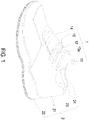
- FIG. 1 is a schematic perspective view illustrating a pressure fixing device applied to a shoe according to a preferred embodiment of the present disclosure.
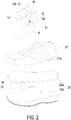
- FIG. 2 is an exploded view illustrating the shoe according to the preferred embodiment of the present disclosure.
- the pressure fixing device 1 of the present disclosure can be applied to various types of footwear, such as sports shoes, sandals, or high-heeled shoes, but is not limited thereto.
- the pressure fixing device 1 is described by taking a sports shoe 2 as an example.
- the sports shoe 2 includes a shoe body 21 and a bottom part 22.
- the shoe body 21 includes a plurality of eyelets 21a for a variety of shoelaces to wear therein.
- the bottom part 22 further includes a shoe pad 22a and a shoe sole 22b, wherein the shoe body 21 and the shoe sole 22b of the bottom part 22 are connected with each other, so as to define a wear space 23 collaboratively.
- the shoe pad 22a is disposed within and spatially corresponding to the wear space 23. Furthermore, the shoe pad 22a and the shoe sole 22b are connected with each other.
- the profile of the shoe pad 22a is substantially the same as the profile of the shoe sole 22b, but the outline of the shoe pad 22a is slightly smaller than that of the shoe sole 22b.
- the appearance and thickness of the shoe pad 22a and the shoe sole 22b can be adjustable according to the practical requirements.
- the pressure fixing device 1 of the present disclosure includes an inflatable shoelace 10, an inflatable shoe tongue 11, a first air pump 12, a second air pump 12', an airbag unit 14, a control module 15, and a battery 16, but not limited thereto.
- the inflatable shoe tongue 11 is connected to the shoe body 21, and an opening 24 is collaboratively defined by the inflatable shoe tongue 11 and the shoe body 21.
- a user's foot can be inserted into or detached from the sports shoe 2 via the opening 24 of the shoe body 21. When the user's foot is inserted into the interior of the sports shoe 2 through the opening 24, the user's foot can be accommodated in the wear space 23.
- the airbag 14 is attached to the inflatable shoe tongue 11, adjacent to one side of the inflatable shoe tongue 11, and in communication with the inflatable shoe tongue 11.
- the inflatable shoelace 10 is attached to the inflatable tongue 11 and adjacent to another side of the inflatable shoe tongue 11, but not limited thereto.
- the first air pump 12 is a one-way inlet air pump, but not limited thereto.
- the control module 15 and the battery 16 are disposed between the shoe pad 22a and the shoe sole 22b of the bottom part 22.
- the control module 15 is electrically connected to the first air pump 12 and the second air pump 12'.
- the battery 16 is used to provide electrical power to the control module 15.
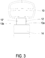
- FIG. 3 schematically illustrates an inflatable shoelace of the pressure fixing device according to the preferred embodiment of the present disclosure.
- the inflatable shoelace 10 is an inflatable and expandable structure with an air and in communication with the airbag 14 through the first air passage 13a and the second air passage 13b for transferring the air.
- the airbag 14 is attached on an outer surface of the inflatable shoe tongue 11.
- the inflatable shoelace 10 runs through the plural eyelets 21a of the shoe body 21.
- the first air passage 13a and the second air passage 13b are in communication between the airbag 14 and the inflatable shoelace 10, respectively.
- the first air pump 12 is disposed within and in communication with the first air passage 13a, and the first air pump 12 is electrically connected to the control module 15 to introduce the air from the inflatable shoelace 10 into the airbag 14, so that the inflatable shoelace 10 is deflated and loosened. Thus, it aids the user to wear or take off the sports shoe 2 easily.
- the second air pump 12' is disposed within and in communication with the second air passage 13b, and the second air pump 12' is electrically connected to the control module 15 to introduce the air from the airbag 14 into the inflatable shoelace 10, so that the air introduced from the inflatable shoe tongue 11 and the airbag 14 is filled into the inflatable shoelace 10.
- the air is quickly filled into the inflatable shoelace 10, and the inflatable shoelace 10 is expanded and tightened to completely attach to the upper portion of the user's instep, namely, the connecting periphery between the user's instep and the ankle.
- the inflatable shoelace 10 and the airbag 14 it prevents the shoe body 21 of the shoe 2 to be bent from pressing the user's foot uncomfortably during exercise, so as to achieve the benefits of comfort and safety.
- the air is controlled to flow between the inflatable shoelace 10 and the inflatable shoe tongue 11 and between the inflatable shoelace 10 and the airbag 14 by the first air pump 12 and the second air pump 12', and the inflatable shoelace 10 is loosened or tightened, so as to achieve the benefits of aiding to wear/take off the shoes and fixing the foot well when putting on it.
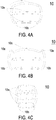
- FIG. 4A schematically illustrates an inflatable shoelace in an initial status according to a first embodiment of the present disclosure.
- FIG. 4B is an exploded view of the inflatable shoelace of FIG. 4A.
- FIG. 4C schematically illustrates the inflatable shoelace of FIG. 4A to be inflated and expanded.
- the inflatable shoelace 10 further includes at least one lacing part 10a and at least one connecting part 10b.
- three lacing parts 10a and two connecting parts 10b are described, but the present disclosure is not limited thereto. The number and arrangement thereof can be adjusted according to the practical requirements. Further as shown in FIG.
- each lacing part 10a includes two through holes 10e disposed on two ends thereof, respectively.
- the connecting part 10b includes through holes (not shown) correspondingly disposed on the surface thereof.
- the lacing part 10a and the connecting part 10b are in communication with each other via the through hole 10e, thereby allowing the air to flow between them.
- the inflatable shoelace 10 is inflated and expanded, as shown in FIG. 4C .
- the three lacing parts 10a of the inflatable shoelace 10 to be inflated and inwardly compressed, it achieves the same tensioning effect as provided by the conventional shoelace.
- the inflatable shoelace 10 is an inflatable and expandable structure, the elasticity of the inflatable shoelace 10 is better and it avoids the uncomfortable feeling due to the poor elasticity when fastened as the conventional shoelace does.
- the inflatable shoelace 10 is deflated and loosened to return to the initial state, as shown in FIG. 4A .
- the three lacing parts 10a of the inflatable shoelace 10 to be deflated and loosened outwardly, it achieves the same unfastening effect as provided by the conventional shoelace and aids the user to wear or take off the sports shoe 2 easily.
- the inflatable shoelace 10 is an artificial-muscle air-inflated shoelace, made of an electroactive polymer, such as the amino acid, which is a smart polymer material that can be controlled by the electric energy.
- the internal structure of the material can be stretched, bent, tightened or expanded, and has the bio-muscle-like elasticity and softness.
- the artificial-muscle air-inflated shoelace provides the user with an excellent wearing experience of the sports shoe 2.
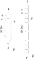
- FIG. 4D schematically illustrates an inflatable shoelace in an initial status according to a second embodiment of the present disclosure.
- FIG. 4E schematically illustrates the inflatable shoelace of FIG. 4D to be inflated and expanded.
- the lacing part 10a of the inflatable shoelace 10 further includes plural expandable sections 10f, plural communication sections 10g and two through holes 10e.
- the plural communication sections 10g are disposed in an up-and-down staggered arrangement having plural communication sections 10g arranged alternately with each other without aligning on the same line.
- Each communication section 10g is connected between the two adjacent expandable sections 10f, and each gap 10h is defined between two adjacent expandable sections 10f, so that a strip-like shoelace structure with the plural "inverted S-shaped" links is formed, but not limited thereto.
- the two through holes 10e are disposed on two ends of the lacing part 10a, but not limited thereto.
- the lacing part 10a of the inflatable shoelace 10 is deflated and loosened to return to the initial state, as shown in FIG. 4D .
- the lacing parts 10a to be deflated and loosened it achieves the same unfastening effect as provided by the conventional shoelace and aids the user to wear or take off the sports shoe 2 easily.
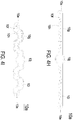
- FIG. 4F schematically illustrates an inflatable shoelace in an initial status according to a third embodiment of the present disclosure.
- FIG. 4G schematically illustrates the inflatable shoelace of FIG. 4F to be inflated and expanded.
- the lacing part 10a of the inflatable shoelace 10 further includes plural expandable sections 10f, plural communication sections 10g and two through holes 10e.
- Each communication section 10g is connected between the two adjacent expandable sections 10f, and plural gaps 10h are defined between two adjacent expandable sections 10f, respectively, so that a strip-like shoelace structure is formed, but not limited thereto.
- the two through holes 10e are disposed on two ends of the lacing part 10a, but not limited thereto.
- the plural expandable sections 10f and the plural communication sections 10g are inflated and expanded and the plural gaps 10h are compressed to make the lacing part 10a inflated and inwardly compressed, as shown in FIG. 4G .
- the lacing part 10a of the inflatable shoelace 10 is deflated and loosened to return to the initial state, as shown in FIG. 4F .
- the lacing parts 10a With the lacing parts 10a to be deflated and loosened, it achieves the same unfastening effect as provided by the conventional shoelace and aids the user to wear or take off the sports shoe 2 easily.
- FIG. 4H schematically illustrates an inflatable shoelace in an initial status according to a fourth embodiment of the present disclosure.
- FIG. 4I schematically illustrates the inflatable shoelace of FIG. 4H to be inflated and expanded.
- the lacing part 10a of the inflatable shoelace 10 further includes two through holes 10e, plural expandable sections 10f, plural communication sections 10g and an outer portion 10i.
- the plural expandable sections 10f and the plural communication sections 10g are disposed in the outer portion 10i, and in communication with each other.
- the two through holes 10e are disposed on two ends of the outer portion 10i, and the plural expandable sections 10f disposed on two ends of the outer portion 10i are in communication with the two through holes 10e for the flow of the air.
- Each communication section 10g is connected between the two adjacent expandable sections 10f, and plural gaps 10h are defined between two adjacent expandable sections 10f, respectively, so that a strip-like shoelace structure is formed, but the present disclosure is not limited thereto.
- the lacing part 10a of the inflatable shoelace 10 is deflated and loosened to return to the initial state, as shown in FIG. 4H .
- the lacing parts 10a to be deflated and loosened it achieves the same unfastening effect as provided by the conventional shoelace and aids the user to wear or take off the sports shoe 2 easily.
- the inflatable shoelace 10 can also be used alone to replace the shoelaces of the conventional footwear, and the lacing portion 10a of the inflatable shoelace 10 further includes an inlet nozzle 10j.
- the inlet nozzle 10j is also in communication with the expandable sections 10f through the communication sections 10g for connecting to an external pumping device, such as an air pump, an inflator and so on.
- FIG. 4J schematically illustrates an inflatable shoelace in an initial status according to a fifth embodiment of the present disclosure.
- FIG. 4K schematically illustrates the inflatable shoelace of FIG. 4J to be inflated and expanded.
- the lacing part 10a of the inflatable shoelace 10 further includes two through holes 10e, plural expandable sections 10f, plural communication sections 10g and an outer portion 10i.
- the plural expandable sections 10f and the plural communication sections 10g are disposed in the outer portion 10i, and in communication with each other.
- the two through holes 10e are disposed on two ends of the outer portion 10i, and the plural expandable sections 10f disposed on two ends of the outer portion 10i are in communication with the two through holes 10e for the flow of the air.
- Each communication section 10g is connected between the two adjacent expandable sections 10f, and plural gaps 10h are defined between two adjacent expandable sections 10f, respectively, so that a strip-like shoelace structure is formed, but the present disclosure is not limited thereto.
- the lacing part 10a of the inflatable shoelace 10 When the air is introduced into the inflatable shoelace 10, the lacing part 10a of the inflatable shoelace 10 is inflated and expanded, and the plural expandable sections 10f and the plural communication sections 10g of the inflatable shoelace 10 are inflated and expanded and the plural gaps 10h are compressed to make the lacing part 10a inflated and inwardly compressed, as shown in FIG. 4K . It achieves the same tensioning effect as provided by the conventional shoelace, so as to fix and fit with the user's foot. Alternatively, when the air is led out of the inflatable shoelace 10, the lacing part 10a of the inflatable shoelace 10 is deflated and loosened to return to the initial state, as shown in FIG. 4J .
- the inflatable shoelace 10 can also be used alone to replace the shoelaces of the conventional footwear, and the lacing portion 10a of the inflatable shoelace 10 further includes an inlet nozzle 10j.
- the inlet nozzle 10j is also in communication with the communication sections 10g for connecting to an external pumping device, such as an air pump, an inflator and so on.
- FIG. 5A is a cross-sectional view illustrating the inflatable shoe tongue of FIG. 2 in an inflated and expanded status and taken along the line AA.
- FIG. 5B schematically illustrates the inflatable shoe tongue of FIG. 5A in an initial status.
- the inflatable shoe tongue 11 is an inflatable and expandable structure with the air, and connected with the shoe body 21.
- the inflatable shoe tongue 11 is disposed and spatially corresponding to the user's instep, but not limited thereto.
- the inflatable shoe tongue 11 includes an outer surface 11c having plural protrusions 11a. Each two adjacent protrusions 11a includes a gap 11b disposed therebetween.
- the inflatable shoe tongue 11 When the air is introduced into the inflatable shoe tongue 11, the inflatable shoe tongue 11 is inflated and expanded. With the plural protrusions 11a on the outer surface 11c to be expanded to protrude outwardly, it makes the inflatable shoe tongue 11 to protrude and bulge in a second direction away from the wear space 23 and the opening 24 is enlarged, so as to aid the user to wear or take off the sports shoe 2 easily. Afterward, as shown in FIG. 5B , when the air is led out of the inflatable shoe tongue 11, the inflatable shoe tongue 11 is deflated and compressed inwardly. With the plural protrusions 11a on the outer surface 11c to be compressed inwardly, it makes the inflatable shoe tongue 11 to shrink in a first direction toward the wear space 23 to return to the initial statue as shown in FIG. 5B . Thus, the user's foot is fixed in the sports shoe 2 firmly.
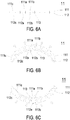
- FIG. 6A is a cross-sectional view illustrating the inflatable shoe tongue according to another preferred embodiment of the present disclosure.
- FIG. 6B schematically illustrates an outer airbag of the inflatable shoe tongue of FIG. 6A in an inflated and expanded status.
- FIG. 6C schematically illustrates an inner airbag of the inflatable shoe tongue of FIG. 6A in an inflated and expanded status.
- the inflatable shoe tongue 11 includes an outer airbag 111, an inner airbag 112 and a two-way valve 113.
- the outer airbag 111 includes an outer surface 111c having plural protrusions 111a protruding outwardly, and a gap 111b is disposed between each two adjacent protrusions 111a of the outer airbag 111.
- the inner airbag 112 includes an inner surface 112c having plural protrusions 112a protruding inwardly, and a gap 112b is disposed between each two adjacent protrusion 112a of the inner airbag 112.
- the two-way valve 113 is a two-way air intake structure and in communication between the outer airbag 111 and the inner airbag 112. The two-way valve 113 is electrically connected with the control module 15.
- the two-way valve 113 With the two-way valve 113 to introduce the air into the plural protrusions 111a of the outer airbag 111, it makes the outer airbag 111 expanded in the second direction to protrude outwardly to move the inflatable shoe tongue 11 away from the wear space 23, and the opening 24 is expanded, so as to aid the user to wear or take off the sports shoe 2 easily.
- the two-way valve 113 to introduce the air into the plural protrusions 112a of the inner airbag 112 it make the inner airbag 112 expanded in the first direction to protrude inwardly to move the inflatable shoe tongue 11 toward the wear space 23, and the opening 24 and the wear space 23 are shrunk inwardly, so as to aid the user's foot to be fixed in the sports shoe 2 firmly.
- the inflatable shoe tongue 11 can be controlled to protrude inwardly or outwardly, and the effects of fastening and loosening can be achieved by using the inflatable shoe tongue 11 of the pressure fixing device 1 without the shoelaces.
- FIG. 7A schematically illustrates the structure of the pressure fixing device applied to the shoe according to the preferred embodiment of the present disclosure.
- FIG. 8 schematically illustrates the flow of the air in the pressure fixing device according to the preferred embodiment of the present disclosure.
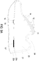
- FIG. 9A is a cross-sectional view illustrating the shoe in an initial status according to the preferred embodiment of the present disclosure.
- FIG. 9B is a cross-sectional view illustrating the shoe in a wearing status according to the preferred embodiment of the present disclosure.
- the pressure fixing device 1 further includes a switch 17.
- the switch 17 is electrically connected to the control module 15.
- the switch 17 is provided for the user to control the pressure fixing device 1.
- FIGS 7A to 9B For describing the specific implementation, please refer to FIGS 7A to 9B .
- the user turns on the switch 17 and the switch 17 sends the second enabling signal to the control module 15, so that the control module 15 enables the second air pump 12' to operate according the second enabling signal. Consequently, the air is introduced from the inflatable shoe tongue 11 and the airbag 14 into the inflatable shoelace 10, the inflatable shoe tongue 10 shrinks in the first direction toward the wear space 23 and the inflatable shoelace 10 is expanded and tighten to attach to the user's instep.
- the switch 17 when the user's foot has to get out of the sports shoe 2, the user turns off the switch 17 and the switch 17 sends a first enabling signal to the control module 15, so that the control module 15 enables the first air pump 12 to operate according to the first enabling signal. Consequently, the air is introduced from the inflatable shoelace 10 into the inflatable shoe tongue 11 and the airbag 14, the inflatable shoelace 10 is deflated and loosened, and the inflatable shoe tongue 11 is expanded due to the air inflated and protrudes away from the wear space 23. Meanwhile, the inflatable shoe tongue 11 has an end adjacent to the airbag 14 to be pressed and another end to be lifted, so that the opening 24 collaboratively defined by the inflatable shoe tongue 11 and the shoe body 21 is expanded. It aids the user to wear or take off the sports shoe 2 easily (as shown in FIG. 9A ).
- the switch 17 is this embodiment can be disposed in the shoe body 21 (not shown), but not limited thereto.
- FIG. 7B schematically illustrates the structure of the pressure fixing device applied to the shoe according to another preferred embodiment of the present disclosure.
- the pressure fixing device 1 further includes a weight sensor 17'.
- the weight sensor 17' is electrically connected to the control module 15.
- the weight sensor 17' can be disposed in the bottom part 22 of the sports shoe 2, but not limited thereto.
- the weight sensor 17' sends the second enabling signal to the control module 15 and the control module 15 enables the second air pump 12' to operate according the second enabling signal.
- the air is introduced from the inflatable shoe tongue 11 into the inflatable shoelace 10, the inflatable shoe tongue 11 shrinks in the first direction toward the wear space 23 and the inflatable shoelace 10 is expanded and tighten to attach to the user's instep.
- the inflatable shoelace 10 of the sports shoe 2 is inflated and pressed inwardly to achieve the effect of automatic fixing.
- the pressure fixing device 1 further includes a first air pressure sensor (not show).
- the first air pressure sensor is disposed within the inflatable shoe tongue 11 and electrically connected with the control module 15.
- the first air pressure sensor detects that the inflatable shoe tongue 11 has an internal pressure higher than a specific threshold interval
- the first air pressure sensor sends a first disabling signal to the control module 15 and the control module 15 disables the first air pump 12 to stop operating according to the first disabling signal.
- the pressure fixing device 1 further includes a second air pressure sensor (not shown).
- the second air pressure sensor is disposed within the inflatable shoelace 10 and electrically connected to the control module 15.
- the second air pressure sensor detects that the inflatable shoelace 10 has an internal pressure higher than the specific threshold interval
- the second air pressure sensor sends a second disabling signal to the control module 15 and the control module 15 disables the second air pump 12' to stop operating according to the second disabling signal.
- the pressure fixing device 1 further includes an inlet valve (not shown) embedded in the outer surface 11c of the inflatable shoe tongue 11 and electrically connected to the control module 15.
- the first air pressure sensor or the second air pressure sensor detects that the internal pressure of the inflatable shoelace 10 or the inflatable shoe tongue 11 is lower than the specific threshold interval
- the first air pressure sensor or the second air pressure sensor sends a gas-filling signal to the control module 15 and the control module 15 drives the inlet valve according to the gas-filling signal to introduce the air from outside into the inflatable shoe tongue 11 of the pressure fixing device 1.
- the control module 15 drives the inlet valve according to the gas-filling signal to introduce the air from outside into the inflatable shoe tongue 11 of the pressure fixing device 1.
- the inflatable shoelace 10 of the pressure fixing device 1 can be replaced by the conventional shoelace, and the pressure fixing device 1 can achieve the effect of fixing or unfastening by using the inflatable shoe tongue 11 merely.
- the first air pump 12 and the second air pump 12' are in communication between the outside of the pressure fixing device 1 and the inflatable shoe tongue 11. With the first air pump 12 to lead the air out of the inflatable shoe tongue 11 and the airbag 14 of the pressure fixing device 1, the inflatable shoe tongue 11 is shrunk toward the wear space 23 to fit with the user's foot.
- the inflatable shoe tongue 11 is expanded due to the inflated air and protrudes in the second direction away from the wear space 23 to enlarge the opening 24, thereby aiding the user to wear the sports shoe 2 easily.
- FIG. 10A is a front exploded view illustrating the air pump not forming part of the invention.
- FIG. 10B is a rear exploded view illustrating the air pump according to the preferred example of the present disclosure.
- the first air pump 12 is a piezoelectric air pump for driving the flow of the air.
- the first air pump 12 of the present disclosure includes a resonance plate 122, a piezoelectric actuator 123 and the cover plate 126.
- the resonance plate 122 is disposed spatially corresponding to the piezoelectric actuator 123.
- the resonance plate 122 includes a central aperture 1220 and a movable part (not shown).
- the central aperture 1220 is disposed on the central area of the resonance plate 122, but not limited thereto.
- the movable part is disposed around the central aperture 1220, so that the movable part of the resonance plate is reciprocated along with the piezoelectric actuator to generate a resonance air flowing.
- the piezoelectric actuator 123 includes a suspension plate 1231, an outer frame 1232 and a piezoelectric element 1233.
- the suspension plate 1231 can be but not limited to a square suspension plate with a bulge 1231e.
- the suspension plate 1231 includes a central portion 1231c and a peripheral portion 1231d.
- the outer frame 1232 is arranged outside around the suspension plate 1231 and includes at least one bracket 1232a and a conducting pin 1232b, but not limited thereto.
- Each bracket 1232a includes two ends connected between the suspension plate 1231 and the outer frame 1232 for providing an elastically supporting.
- the conducting pin 1232b protrudes outwardly from the outer frame 1232 for an electrically external connection.
- the piezoelectric element 1233 is attached to a second surface 1231b of the suspension plate 1231.
- the length of a side of the piezoelectric element 1233 is equal to or less than the length of a side of the suspension plate 1231, so as to receive the applied voltage and generate the deformation to drive the bending vibration of the suspension plate 1231.
- the cover plate 126 includes at least one sidewall 1261, a bottom plate 1262 and an opening portion 1263.
- the sidewalls 1261 surrounds and protrudes vertically from a periphery of the bottom plate 1262, so as to define an accommodation space 126a by the sidewalls 1261 and the bottom plate 1262 collaboratively.
- the resonance plate 122 and the piezoelectric actuator 123 are accommodated within the accommodation space 126a.
- the opening portion 1263 is disposed on the sidewall 1261 so that the conducting pin 1232b of the outer frame 1232 passes through the opening portion 1263 and protrudes out of the cover plate 126. It's beneficial for the conducting pin 1232b to connect with an external power, but the present disclosure is not limited thereto.
- the first air pump 12 of the present disclosure further includes a first insulation plate 1241, a second insulation plate 1242 and a conducting plate 125, but not limited thereto.
- the first insulation plate 1241 and the second insulation plate 1242 are disposed on the top and the bottom of the conducting plate 125, respectively, and have the profiles substantially matching the profile of the outer frame 1232 of the piezoelectric actuator 123.
- the first insulation plate 1241 and the second insulation plate 1242 can be made of an insulating material, for example but not limited to a plastic material, for providing insulating efficacy.
- the conducting plate 125 is made of an electrically conductive material, for example but not limited to a metallic material, for providing electrically conducting efficacy.
- the conducting plate 125 has its profile substantially matching the profile of the outer frame 1232 of the piezoelectric actuator 123, but the present disclosure is not limited thereto. Moreover, the conducting plate 125 may have a conducting pin 1251 for an electrically external conduction. The conducting pin 1251 is similar to the conducting pin 1232b of the outer frame 1232 to pass through the opening portion 1263 and protrude out of the cover plate 126 for electrically connecting to the control module 15.
- FIG. 11A is a front view illustrating the piezoelectric actuator of FIGS. 10A and 10B .
- FIG. 11B is a rear view illustrating the piezoelectric actuator of FIGS. 10A and 10B .
- FIG. 11C is a cross-sectional view illustrating the piezoelectric actuator of FIGS. 10A and 10B .
- the suspension plate 1231 has a stepped structure.
- the suspension plate 1231 further includes a bulge 1231e disposed on the central portion 1231c of the first surface 1231a.
- the bulge 1231e can be a circular protrusion structure, but not limited thereto.
- the suspension plate 1231 can be a double-sided planar square plate. Further as shown in FIG. 11C , the bulge 1231e of the suspension plate 1231 and the first surface 1232c of the outer frame 1232 are coplanar, and the first surface 1231a of the suspension plate 1231 and the first surface 1232a' of the bracket 1232a are coplanar. In addition, the bulge 1231e of the suspension plate 1231 and the first surface 1232c of the outer frame 1232 have a specific depth relative to the first surface 1231a of the suspension plate 1231 and the first surface 1232a' of the bracket 1232a. As shown in FIGS.
- the second surface 1231b of the suspension plate 1231, the second surface 1232d of the outer frame 1232 and the second surface 1232a" of the bracket 1232a are formed as a flat coplanar structure.
- the piezoelectric element 1233 is attached to the flat second surface 1231b of the suspension plate 1231.
- the suspension plate 1231 can be a double-sided planar square plate, but not limited thereto. It is adjustable according to the practical requirements.
- the suspension plate 1231, the outer frame 1232 and the bracket 1232a can be formed as an integrated structure, and made of a metal plate, for example but not limited to a stainless steel plate.
- the first air pump 12 further includes at least one interspace 1234 disposed among the suspension plate 1231, the outer frame 1232 and the bracket 1232a for the air passing therethrough.
- FIG. 12 is a cross-sectional view illustrating the air pump of FIGS. 10A and 10B .
- the first air pump 12 includes the cover plate 126, the second insulation plate 1242, the conducting plate 125, the first insulation plate 1241, the piezoelectric actuator 123 and the resonance plate 122 stacked on each other from top to bottom sequentially.
- an adhesive 128 is coated around the periphery of the assembled structure to accomplish sealing.
- the assembled first air pump 12 is a quadrilateral structure, but not limited thereto. The shape can be adjustable according to the practical requirements.
- the conducting pin 1251 of the conducting plate 125 and the conducting pin 1232b (shown in FIG. 10A ) of the piezoelectric actuator 123 protrude out of the cover plate 126 merely for electrically connecting with an external power, but not limited thereto.
- the first chamber 127b is formed between the cover plate 126 and the resonance plate 122 in the assembled first air pump 12.
- the first air pump 12 of the present disclosure includes a gap g0 disposed between the resonance plate 122 and the piezoelectric actuator 123, and a conductive material, for example but not limited to a conductive adhesive, is filled into the gap g0. Consequently, the depth of the gap g0 between the resonance plate 122 and the bulge 1231e of the suspension plate 1231 of the piezoelectric actuator 123 is maintained, which is capable of guiding the air to flow more quickly. Moreover, due to the proper distance between the bulge 1231e of the suspension plate 1231 and the resonance plate 122, the contact interference is reduced and thus the generated noise is largely reduced.
- a conductive material for example but not limited to a conductive adhesive
- the present disclosure is not limited thereto.
- the piezoelectric actuator 123 when the piezoelectric actuator 123 is driven to converge the air, the air is transferred from the opening portion 1263 of the cover plate 126 to the convergence chamber 127a, and then temporarily stored in the first chamber 127b through the central aperture 1220 of the resonance plate 122.
- the piezoelectric actuator 123 is driven to discharge the air, the air is transferred from the first chamber 127b to the convergence chamber 127a through the central aperture 1220 of the resonance plate 122, and introduced into the inflatable shoe tongue 11 through the inflatable shoelace 10.
- FIGS. 13A to 13D illustrate an operating process of the air pump according to a preferred example of the present disclosure.
- the structure of the first air pump 12 is similar to that in the foregoing descriptions and assembled and stacked sequentially by the order of the cover plate 126, the second insulation plate 1242, the conducting plate 125, the first insulation plate 1241, the piezoelectric actuator 123 and the resonance plate 122.
- the resonance plate 122 and the sidewalls 1261 of the cover plate 126 collaboratively define the convergence chamber 127a.
- the first chamber 127b is formed between the resonance plate 122 and the piezoelectric actuator 123 spaced apart by the gap g0.
- the resonance plate 122 is influenced by the resonance of the suspension plate 1231 of the piezoelectric actuator 123 to generate a reciprocating vibration. Namely, the resonance plate 122 is deformed upwardly. The resonance plate 122 protrudes slightly at central aperture 1220.
- the piezoelectric actuator 123 vibrates downwardly to the original position. Meanwhile, the bulge 1231e of the suspension plate 1231 of the piezoelectric actuator 123 is close to the upward protruded portion of the resonance plate 122 at the central aperture 1220. It makes the air in the first air pump 12 temporarily stored in the upper half layer of the first chamber 127b.
- the piezoelectric actuator 123 further vibrates downwardly and the resonance plate 122 also vibrates downwardly due to the resonance of the piezoelectric actuator 123.
- the air in the upper half layer of the first chamber 127b is pushed to flow toward the both sides and pass through the interspace 1234 of the piezoelectric actuator 123 downwardly, so as to be transferred to the central aperture 1220 of the resonance plate 122 and compressed to discharge.
- the gap g0 between the resonance plate 122 and the piezoelectric actuator 123 facilitates to increase the maximum distance in the vertical displacement.
- the gap g0 disposed between the resonance plate 122 and the piezoelectric actuator 123 allows the resonance plate 122 to generate a greater amplitude of the up and down displacement when it is in resonance.
- the resonance plate 122 returns to the original position as shown in FIG. 13A .
- the circulation in the order of FIGS 13A to 13D is maintained continuously.
- the air is fed from the opening portion 1263 of the cover plate 126 into the convergence chamber 127a and then flows to the first chamber 127b. Afterward, the air is further transferred from the first chamber 127b to the convergence chamber 127a, so that the air flows from the inflatable shoelace 10 to the inflatable shoe tongue 11 continuously and is transferred stably.
- the first air pump 12 of the present disclosure when the first air pump 12 of the present disclosure is operated, the air flows through the opening portion 1263 of the cover plate 126, the convergence chamber 127a, the first chamber 127b, the convergence chamber 127a and the inlet opening 204 sequentially.
- the first air pump 12 of the present disclosure provides a single component, the cover plate 126, and utilizes the structural design of the opening portion 1263 of the cover plate 126, so that the number of components of the first air pump 12 can be reduced, and the entire process can be simplified.
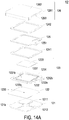
- FIG. 14A is a front cross-sectional view illustrating the air pump according to another preferred example of the present disclosure.
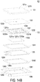
- FIG. 14B is a rear cross-sectional view illustrating the air pump of FIG. 14A .
- the first air pump 12 includes the cover plate 126, the second insulation plate 1242, the conducting plate 125, the first insulation plate 1241, the piezoelectric actuator 123 and the resonance plate 122 stacked on each other sequentially.
- the first air pump 12 has the similar structures, elements and configurations as those of the above examples and is not redundantly described herein.
- the first air pump 12 further includes an inlet plate 121.
- the inlet plate 121 is aligned with the resonance plate 122 and stacked thereon.
- the inlet plate 121 includes a first surface 121a, a second surface 121b and at least one inlet 1210.
- the inlet plate 121 has four inlets 1210, but not limited thereto.
- the inlets 1210 runs through the first surface 121a and the second surface 121b, so that the air is fed into the first air pump 12 through the at least one inlet 1210 in response to the action of the atmospheric pressure.
- the inlet plate 121 includes at least one convergence channel 1212 disposed on the second surface 121b and spatially corresponding to the at least one inlet 1210 on the first surface 121a of the inlet plate 121.
- the central cavity 1211 is in communication with the convergence channels 1212.
- the air fed into the convergence channels 1212 through the at least one inlet 1210 can be converged and transferred to the central cavity 1211, so as to converge the air at the central aperture 1220 of the resonance plate 122 efficiently and transfer the air to the inner of the first air pump 12.
- the inlet plate 121 is integrally formed by the inlets 1210, the convergence channels 1212 and the central cavity 1211, and a convergence chamber is formed corresponding to the central cavity 1211 to store the air temporarily.
- the material of the inlet plate 121 can be for example but not limited to the stainless steel.
- the depth of the convergence chamber formed at the central cavity 1211 and the depth of those convergence channels 1212 can be, for example but not limited to, equal.
- the resonance plate 122 can be made of for example but not limited to a flexible material.
- the resonance plate 122 has a central aperture 1220 corresponding to the central cavity 1211 on the second surface 121b of the inlet plate 121, so as to allow the air to flow downwardly.
- the resonance plate 122 can be made of for example but not limited to a copper material.
- the air is introduced into the inflatable shoe tongue 11 through the inflatable shoelace 10, so that the inflatable shoelace 10 is deflated and relaxed and the inside of the inflatable tongue 11 is expanded due to the inflated air to protrude outwardly.
- the openings 24 and the wear space 23 of the sports shoe 2 are expanded to aid the user to wear or take off the sports shoe 2 easily.
- the structure of the second air pump 12' of the present disclosure is similar to that of the first air pump 12, and is not be redundantly described herein.
- the inflatable shoelace 10 With the second air pump 12' to pump the air from the inflatable shoe tongue 11 to the airbag 14, the inflatable shoelace 10 can be inflated and tightened and the air in the inflatable shoe tongue 11 can be deflated to shrink inwardly. Thus, the opening 24 and the wear space 23 of the sports shoe 2 are reduced, so as to fix the user's foot within the sports shoe 2 firmly.
- the present disclosure provides a pressure fixing device applied to a shoe.
- the weight sensor is utilized to detect the pressure of weight to confirm that the user is wearing or the taking-off the shoe.
- the control module enables the first air pump or the second air pump.
- the inflatable shoe tongue can be controlled to be deflated and shrunk inwardly and the inflatable shoelace can be controlled to be inflated and tightened, so as to fix the user's foot firmly.
- the inflatable shoe tongue can be controlled to be inflated and expanded outwardly and the inflatable shoelace can be controlled to be deflated and loosened, so as to aid the user to wear or take off easily.
- the pressure fixing device further has the function of adjusting the pressure.
- the control module can maintain the internal pressure in a specific range. It avoids the discomfort of the foot due to the over-inflation of the inflatable shoe tongue and the inflatable shoelace or the airbag burst, and provide a more comfortable pressure for the user to wear.
Landscapes
- Engineering & Computer Science (AREA)
- Microelectronics & Electronic Packaging (AREA)
- Mechanical Engineering (AREA)
- General Engineering & Computer Science (AREA)
- Footwear And Its Accessory, Manufacturing Method And Apparatuses (AREA)
Description
- The present disclosure relates to a pressure fixing device applied to a shoe, and more particularly to a pressure fixing device applied to a shoe and inflated by an air pump
- Generally, shoelaces are used in most shoes as a means of loosening, tying and fixing the shoes on the feet. However, the shoes with shoelaces have many problems of inconvenience when putting on it. For example, when the shoelaces are loosened while moving, they have to be retied, resulting in inconvenience and waste of time. Furthermore, there is also potential danger of wearing shoes with shoelaces. For example, when the shoelaces are accidentally loosened, other people may trip over it, or the shoelaces may be involved in the gap of an escalator, a bicycle chain or a motorcycle pin etc., which may cause accidents. In addition, wearing the shoes with shoelaces in long term may put excessive pressure on the feet and cause discomfort.
- Some shoes use other ways, such as a hook and loop fastener or a sock-type shoe body, as a means of loosening, tying, and fixing the feet. However, the hook and loop fastener has insufficient fixity, and is easily detached. The viscosity of the hook and loop fastener may decrease after using for a long period of time, resulting in inconvenience while moving, and the shoes with the hook and loop fastener are inappropriate for wearing during exercise. The sock-type shoe body also has insufficient strength to fix the feet, and the tightness cannot be adjusted according to the requirements. After using for a long period of time, the sock-type shoe body may be loose, and the requirement of fixing the feet is failed to be achieved.
- On the other hand, in general, the topline opening of a conventional footwear is mainly designed based on its functionality. For example, sports shoes usually have a narrower topline opening so as to provide the better coverage and avoid being detached during the movement. However, the design of the narrower topline opening in the sports shoes doesn't facilitate the user's foot to fit with the shoe. If the topline opening of shoe is forced to widen for convenience of wearing, it will cause the topline opening to loosen and loss the functions of wrapping and protection. Alternatively, for example, casual shoes usually have a wider topline opening so as to aid the users to wear or take off easily. However, the design of the wider topline opening in the casual shoes will cause the user's foot to detach from the shoe easily, or increase the risks of injuring the user's foot or damaging the shoe.
- Therefore, there is a need of providing a pressure fixing device to solve the drawbacks in prior arts, which can be applied to each of a pair of shoes and making the shoe automatically adjustable to be adapted to the personal foot shapes and comfortably wrap and fix the feet.
-
US 5,588,227 A relates to an athletic shoe having an inflatable air bladder integrated into the design and construction of the shoe, and to an apparatus for inflating the air bladder, as well as an apparatus for sensing and indicating the pressure in the bladder, all incorporated into the design of the shoe. - An object of the present disclosure provides a pressure fixing device applied to a shoe. The topline opening disposed on each of a pair of shoes can be adjustable to wrap the foot comfortably. Simultaneously, it achieves the benefits of aiding to wear/take off the shoes and fixing the foot well while wearing.
- The invention is defined by the independent claim. Preferred embodiments are the subject of the dependent claims.
- In accordance with an aspect of the present disclosure, there is provided a pressure fixing device applied to a shoe. The shoe includes a shoe body and a bottom part. The shoe body includes plural eyelets. The bottom part is connected to the shoe body to define a wear space collaboratively. The pressure fixing device includes an inflatable shoe tongue, a first air pump and a control module. The inflatable shoe tongue is connected to the shoe body. The inflatable shoe tongue is an inflatable and expandable structure with an air. An opening is collaboratively defined by the inflatable shoe tongue and the shoe body. The opening is in communication with the wear space. The first air pump is in communication with the inflatable shoe tongue. The control module is electrically connected to the first air pump. The control module drives the air flowing out of the inflatable shoe tongue according to a second enabling signal so that the inflatable shoe tongue shrinks in a first direction toward the wear space to attach to a user's instep. The control module drives the first air pump to pump the air flowing into the inflatable shoe tongue according to a first enabling signal, so that the inflatable shoe tongue expands and bulges in a second direction away from the wear space to enlarge the opening.
- The above contents of the present disclosure will become more readily apparent to those ordinarily skilled in the art after reviewing the following detailed description and accompanying drawings, in which:
-
-
FIG. 1 is a schematic perspective view illustrating a pressure fixing device applied to a shoe according to a preferred embodiment of the present disclosure; -
FIG. 2 is an exploded view illustrating the shoe according to the preferred embodiment of the present disclosure; -
FIG. 3 schematically illustrates an inflatable shoelace of the pressure fixing device according to the preferred embodiment of the present disclosure; -
FIG. 4A schematically illustrates an inflatable shoelace in an initial status according to a first embodiment of the present disclosure; -
FIG. 4B is an exploded view of the inflatable shoelace ofFIG. 4A ; -
FIG. 4C schematically illustrates the inflatable shoelace ofFIG. 4A to be inflated and expanded; -
FIG. 4D schematically illustrates an inflatable shoelace in an initial status according to a second embodiment of the present disclosure; -
FIG. 4E schematically illustrates the inflatable shoelace ofFIG. 4D to be inflated and expanded; -
FIG. 4F schematically illustrates an inflatable shoelace in an initial status according to a third embodiment of the present disclosure; -
FIG. 4G schematically illustrates the inflatable shoelace ofFIG. 4F to be inflated and expanded; -
FIG. 4H schematically illustrates an inflatable shoelace in an initial status according to a fourth embodiment of the present disclosure; -
FIG. 4I schematically illustrates the inflatable shoelace ofFIG. 4H to be inflated and expanded; -
FIG. 4J schematically illustrates an inflatable shoelace in an initial status according to a fifth embodiment of the present disclosure; -
FIG. 4K schematically illustrates the inflatable shoelace ofFIG. 4J to be inflated and expanded; -
FIG. 5A is a cross-sectional view illustrating the inflatable shoe tongue ofFIG. 2 in an inflated and expanded status and taken along the line AA; -
FIG. 5B schematically illustrates the inflatable shoe tongue ofFIG. 5A in an initial status; -
FIG. 6A is a cross-sectional view illustrating the inflatable shoe tongue according to another preferred embodiment of the present disclosure; -
FIG. 6B schematically illustrates an outer airbag of the inflatable shoe tongue ofFIG. 6A in an inflated and expanded status; -
FIG. 6C schematically illustrates an inner airbag of the inflatable shoe tongue ofFIG. 6A in an inflated and expanded status; -
FIG. 7A schematically illustrates the structure of the pressure fixing device applied to the shoe according to the preferred embodiment of the present disclosure; -
FIG. 7B schematically illustrates the structure of the pressure fixing device applied to the shoe according to another preferred embodiment of the present disclosure; -
FIG. 8 schematically illustrates the flow of the air in the pressure fixing device according to the preferred embodiment of the present disclosure; -
FIG. 9A is a cross-sectional view illustrating the shoe in an initial status according to the preferred embodiment of the present disclosure; -
FIG. 9B is a cross-sectional view illustrating the shoe in a wearing status according to the preferred embodiment of the present disclosure; -
FIG. 10A is a front exploded view illustrating the air pump not forming part of the invention; -
FIG. 10B is a rear exploded view illustrating the air pump not forming part of the invention; -
FIG. 11A is a front view illustrating the piezoelectric actuator ofFIGS. 10A and10B ; -
FIG. 11B is a rear view illustrating the piezoelectric actuator ofFIGS. 10A and10B ; -
FIG. 11C is a cross-sectional view illustrating the piezoelectric actuator ofFIGS. 10A and10B ; -
FIG. 12 is a cross-sectional view illustrating the air pump ofFIGS. 10A and10B ; -
FIGS. 13A to 13D illustrate an operating process of the air pump not forming part of the invention; -
FIG. 14A is a front cross-sectional view illustrating the air pump not forming part of the invention; and -
FIG. 14B is a rear cross-sectional view illustrating the air pump ofFIG. 14A . - The present disclosure will now be described more specifically with reference to the following embodiments. It is to be noted that the following descriptions of preferred embodiments of this invention are presented herein for purpose of illustration and description only. It is not intended to be exhaustive or to be limited to the precise form disclosed.
- Please refer to
FIGS. 1 and2 .FIG. 1 is a schematic perspective view illustrating a pressure fixing device applied to a shoe according to a preferred embodiment of the present disclosure.FIG. 2 is an exploded view illustrating the shoe according to the preferred embodiment of the present disclosure. As shown inFIG. 1 , thepressure fixing device 1 of the present disclosure can be applied to various types of footwear, such as sports shoes, sandals, or high-heeled shoes, but is not limited thereto. In this embodiment, thepressure fixing device 1 is described by taking asports shoe 2 as an example. Thesports shoe 2 includes ashoe body 21 and abottom part 22. As shown inFIG. 2 , theshoe body 21 includes a plurality ofeyelets 21a for a variety of shoelaces to wear therein. Thebottom part 22 further includes ashoe pad 22a and a shoe sole 22b, wherein theshoe body 21 and the shoe sole 22b of thebottom part 22 are connected with each other, so as to define awear space 23 collaboratively. Theshoe pad 22a is disposed within and spatially corresponding to thewear space 23. Furthermore, theshoe pad 22a and the shoe sole 22b are connected with each other. The profile of theshoe pad 22a is substantially the same as the profile of the shoe sole 22b, but the outline of theshoe pad 22a is slightly smaller than that of the shoe sole 22b. The appearance and thickness of theshoe pad 22a and the shoe sole 22b can be adjustable according to the practical requirements. - Please refer to
FIGS. 1 and2 again. In this embodiment, thepressure fixing device 1 of the present disclosure includes aninflatable shoelace 10, aninflatable shoe tongue 11, afirst air pump 12, a second air pump 12', anairbag unit 14, acontrol module 15, and abattery 16, but not limited thereto. Theinflatable shoe tongue 11 is connected to theshoe body 21, and anopening 24 is collaboratively defined by theinflatable shoe tongue 11 and theshoe body 21. A user's foot can be inserted into or detached from thesports shoe 2 via theopening 24 of theshoe body 21. When the user's foot is inserted into the interior of thesports shoe 2 through theopening 24, the user's foot can be accommodated in thewear space 23. Theairbag 14 is attached to theinflatable shoe tongue 11, adjacent to one side of theinflatable shoe tongue 11, and in communication with theinflatable shoe tongue 11. Theinflatable shoelace 10 is attached to theinflatable tongue 11 and adjacent to another side of theinflatable shoe tongue 11, but not limited thereto. In this embodiment, thefirst air pump 12 is a one-way inlet air pump, but not limited thereto. In this embodiment, thecontrol module 15 and thebattery 16 are disposed between theshoe pad 22a and the shoe sole 22b of thebottom part 22. Thecontrol module 15 is electrically connected to thefirst air pump 12 and the second air pump 12'. Thebattery 16 is used to provide electrical power to thecontrol module 15. - Please also refer to
FIGS. 2 and3. FIG. 3 schematically illustrates an inflatable shoelace of the pressure fixing device according to the preferred embodiment of the present disclosure. As shown inFIG. 3 , in the embodiment, theinflatable shoelace 10 is an inflatable and expandable structure with an air and in communication with theairbag 14 through thefirst air passage 13a and thesecond air passage 13b for transferring the air. Theairbag 14 is attached on an outer surface of theinflatable shoe tongue 11. Theinflatable shoelace 10 runs through theplural eyelets 21a of theshoe body 21. Thefirst air passage 13a and thesecond air passage 13b are in communication between theairbag 14 and theinflatable shoelace 10, respectively. Thefirst air pump 12 is disposed within and in communication with thefirst air passage 13a, and thefirst air pump 12 is electrically connected to thecontrol module 15 to introduce the air from theinflatable shoelace 10 into theairbag 14, so that theinflatable shoelace 10 is deflated and loosened. Thus, it aids the user to wear or take off thesports shoe 2 easily. In addition, the second air pump 12' is disposed within and in communication with thesecond air passage 13b, and the second air pump 12' is electrically connected to thecontrol module 15 to introduce the air from theairbag 14 into theinflatable shoelace 10, so that the air introduced from theinflatable shoe tongue 11 and theairbag 14 is filled into theinflatable shoelace 10. The air is quickly filled into theinflatable shoelace 10, and theinflatable shoelace 10 is expanded and tightened to completely attach to the upper portion of the user's instep, namely, the connecting periphery between the user's instep and the ankle. Thus, it aids the user's foot to be wrapped and fixed firmly in theshoe 2. In addition, with the two-section configuration of theinflatable shoelace 10 and theairbag 14, it prevents theshoe body 21 of theshoe 2 to be bent from pressing the user's foot uncomfortably during exercise, so as to achieve the benefits of comfort and safety. Therefore, the air is controlled to flow between theinflatable shoelace 10 and theinflatable shoe tongue 11 and between theinflatable shoelace 10 and theairbag 14 by thefirst air pump 12 and the second air pump 12', and theinflatable shoelace 10 is loosened or tightened, so as to achieve the benefits of aiding to wear/take off the shoes and fixing the foot well when putting on it. - Please also refer to
FIGS. 4A and 4B. FIG. 4A schematically illustrates an inflatable shoelace in an initial status according to a first embodiment of the present disclosure.FIG. 4B is an exploded view of the inflatable shoelace ofFIG. 4A. FIG. 4C schematically illustrates the inflatable shoelace ofFIG. 4A to be inflated and expanded. As shown inFIG. 4A , in the first embodiment, theinflatable shoelace 10 further includes at least one lacingpart 10a and at least one connectingpart 10b. In the embodiment, three lacingparts 10a and two connectingparts 10b are described, but the present disclosure is not limited thereto. The number and arrangement thereof can be adjusted according to the practical requirements. Further as shown inFIG. 4B , in the embodiment, each lacingpart 10a includes two throughholes 10e disposed on two ends thereof, respectively. The connectingpart 10b includes through holes (not shown) correspondingly disposed on the surface thereof. The lacingpart 10a and the connectingpart 10b are in communication with each other via the throughhole 10e, thereby allowing the air to flow between them. When the air is introduced into theinflatable shoelace 10, theinflatable shoelace 10 is inflated and expanded, as shown inFIG. 4C . With the threelacing parts 10a of theinflatable shoelace 10 to be inflated and inwardly compressed, it achieves the same tensioning effect as provided by the conventional shoelace. Since theinflatable shoelace 10 is an inflatable and expandable structure, the elasticity of theinflatable shoelace 10 is better and it avoids the uncomfortable feeling due to the poor elasticity when fastened as the conventional shoelace does. When the air is led out of theinflatable shoelace 10, theinflatable shoelace 10 is deflated and loosened to return to the initial state, as shown inFIG. 4A . With the threelacing parts 10a of theinflatable shoelace 10 to be deflated and loosened outwardly, it achieves the same unfastening effect as provided by the conventional shoelace and aids the user to wear or take off thesports shoe 2 easily. In addition, in the embodiment, theinflatable shoelace 10 is an artificial-muscle air-inflated shoelace, made of an electroactive polymer, such as the amino acid, which is a smart polymer material that can be controlled by the electric energy. The internal structure of the material can be stretched, bent, tightened or expanded, and has the bio-muscle-like elasticity and softness. By the properties of being inflatable, expandable or able to be tightened up, the artificial-muscle air-inflated shoelace provides the user with an excellent wearing experience of thesports shoe 2. - Please refer to
FIGS. 4D and 4E. FIG. 4D schematically illustrates an inflatable shoelace in an initial status according to a second embodiment of the present disclosure.FIG. 4E schematically illustrates the inflatable shoelace ofFIG. 4D to be inflated and expanded. As shown inFIG. 4D , in the second embodiment, the lacingpart 10a of theinflatable shoelace 10 further includes pluralexpandable sections 10f,plural communication sections 10g and two throughholes 10e. Theplural communication sections 10g are disposed in an up-and-down staggered arrangement havingplural communication sections 10g arranged alternately with each other without aligning on the same line. Eachcommunication section 10g is connected between the two adjacentexpandable sections 10f, and eachgap 10h is defined between two adjacentexpandable sections 10f, so that a strip-like shoelace structure with the plural "inverted S-shaped" links is formed, but not limited thereto. The two throughholes 10e are disposed on two ends of thelacing part 10a, but not limited thereto. When the air is introduced into theinflatable shoelace 10 via the throughholes 10e, the pluralexpandable sections 10f and theplural communication sections 10g are inflated and expanded and theplural gaps 10h are compressed to make thelacing part 10a inflated and inwardly compressed, as shown inFIG. 4E . It achieves the tensioning same effect as provided by the conventional shoelace, so as to fix and fit with the user's foot. Alternatively, when the air is led out of theinflatable shoelace 10, the lacingpart 10a of theinflatable shoelace 10 is deflated and loosened to return to the initial state, as shown inFIG. 4D . With thelacing parts 10a to be deflated and loosened, it achieves the same unfastening effect as provided by the conventional shoelace and aids the user to wear or take off thesports shoe 2 easily. - Please refer to
FIGS. 4F and 4G. FIG. 4F schematically illustrates an inflatable shoelace in an initial status according to a third embodiment of the present disclosure.FIG. 4G schematically illustrates the inflatable shoelace ofFIG. 4F to be inflated and expanded. As shown inFIG. 4F , in the third embodiment, the lacingpart 10a of theinflatable shoelace 10 further includes pluralexpandable sections 10f,plural communication sections 10g and two throughholes 10e. Eachcommunication section 10g is connected between the two adjacentexpandable sections 10f, andplural gaps 10h are defined between two adjacentexpandable sections 10f, respectively, so that a strip-like shoelace structure is formed, but not limited thereto. The two throughholes 10e are disposed on two ends of thelacing part 10a, but not limited thereto. When the air is introduced into theinflatable shoelace 10 via the throughholes 10e, the pluralexpandable sections 10f and theplural communication sections 10g are inflated and expanded and theplural gaps 10h are compressed to make thelacing part 10a inflated and inwardly compressed, as shown inFIG. 4G . It achieves the same tensioning effect as provided by the conventional shoelace, so as to fix and fit with the user's foot. Alternatively, when the air is led out of theinflatable shoelace 10, the lacingpart 10a of theinflatable shoelace 10 is deflated and loosened to return to the initial state, as shown inFIG. 4F . With thelacing parts 10a to be deflated and loosened, it achieves the same unfastening effect as provided by the conventional shoelace and aids the user to wear or take off thesports shoe 2 easily. - Please refer to
FIGS. 4H and 4I. FIG. 4H schematically illustrates an inflatable shoelace in an initial status according to a fourth embodiment of the present disclosure.FIG. 4I schematically illustrates the inflatable shoelace ofFIG. 4H to be inflated and expanded. As shown inFIG. 4H , in the fourth embodiment, the lacingpart 10a of theinflatable shoelace 10 further includes two throughholes 10e, pluralexpandable sections 10f,plural communication sections 10g and anouter portion 10i. The pluralexpandable sections 10f and theplural communication sections 10g are disposed in theouter portion 10i, and in communication with each other. The two throughholes 10e are disposed on two ends of theouter portion 10i, and the pluralexpandable sections 10f disposed on two ends of theouter portion 10i are in communication with the two throughholes 10e for the flow of the air. Eachcommunication section 10g is connected between the two adjacentexpandable sections 10f, andplural gaps 10h are defined between two adjacentexpandable sections 10f, respectively, so that a strip-like shoelace structure is formed, but the present disclosure is not limited thereto. When the air is introduced into theinflatable shoelace 10 via the throughholes 10e, the pluralexpandable sections 10f and theplural communication sections 10g are inflated and expanded and theplural gaps 10h are compressed to make thelacing part 10a inflated and inwardly compressed, as shown inFIG. 4I . It achieves the same tensioning effect as provided by the conventional shoelace, so as to fix and fit with the user's foot. Alternatively, when the air is led out of theinflatable shoelace 10, the lacingpart 10a of theinflatable shoelace 10 is deflated and loosened to return to the initial state, as shown inFIG. 4H . With thelacing parts 10a to be deflated and loosened, it achieves the same unfastening effect as provided by the conventional shoelace and aids the user to wear or take off thesports shoe 2 easily. In some embodiments, theinflatable shoelace 10 can also be used alone to replace the shoelaces of the conventional footwear, and the lacingportion 10a of theinflatable shoelace 10 further includes aninlet nozzle 10j. Theinlet nozzle 10j is also in communication with theexpandable sections 10f through thecommunication sections 10g for connecting to an external pumping device, such as an air pump, an inflator and so on. - Please refer to
FIGS. 4J and 4K. FIG. 4J schematically illustrates an inflatable shoelace in an initial status according to a fifth embodiment of the present disclosure.FIG. 4K schematically illustrates the inflatable shoelace ofFIG. 4J to be inflated and expanded. As shown inFIG. 4J , in the fifth embodiment, the lacingpart 10a of theinflatable shoelace 10 further includes two throughholes 10e, pluralexpandable sections 10f,plural communication sections 10g and anouter portion 10i. The pluralexpandable sections 10f and theplural communication sections 10g are disposed in theouter portion 10i, and in communication with each other. The two throughholes 10e are disposed on two ends of theouter portion 10i, and the pluralexpandable sections 10f disposed on two ends of theouter portion 10i are in communication with the two throughholes 10e for the flow of the air. Eachcommunication section 10g is connected between the two adjacentexpandable sections 10f, andplural gaps 10h are defined between two adjacentexpandable sections 10f, respectively, so that a strip-like shoelace structure is formed, but the present disclosure is not limited thereto. When the air is introduced into theinflatable shoelace 10, the lacingpart 10a of theinflatable shoelace 10 is inflated and expanded, and the pluralexpandable sections 10f and theplural communication sections 10g of theinflatable shoelace 10 are inflated and expanded and theplural gaps 10h are compressed to make thelacing part 10a inflated and inwardly compressed, as shown inFIG. 4K . It achieves the same tensioning effect as provided by the conventional shoelace, so as to fix and fit with the user's foot. Alternatively, when the air is led out of theinflatable shoelace 10, the lacingpart 10a of theinflatable shoelace 10 is deflated and loosened to return to the initial state, as shown inFIG. 4J . With thelacing parts 10a to be deflated and loosened, it achieves the same unfastening effect as provided by the conventional shoelace and aids the user to wear or take off thesports shoe 2 easily. In some embodiments, theinflatable shoelace 10 can also be used alone to replace the shoelaces of the conventional footwear, and the lacingportion 10a of theinflatable shoelace 10 further includes aninlet nozzle 10j. Theinlet nozzle 10j is also in communication with thecommunication sections 10g for connecting to an external pumping device, such as an air pump, an inflator and so on. - Please refer to
FIGS. 2 ,5A and 5B. FIG. 5A is a cross-sectional view illustrating the inflatable shoe tongue ofFIG. 2 in an inflated and expanded status and taken along the line AA.FIG. 5B schematically illustrates the inflatable shoe tongue ofFIG. 5A in an initial status. As shown inFIG. 2 , in this embodiment, theinflatable shoe tongue 11 is an inflatable and expandable structure with the air, and connected with theshoe body 21. Theinflatable shoe tongue 11 is disposed and spatially corresponding to the user's instep, but not limited thereto. As shown inFIG. 5A , theinflatable shoe tongue 11 includes anouter surface 11c havingplural protrusions 11a. Each twoadjacent protrusions 11a includes agap 11b disposed therebetween. When the air is introduced into theinflatable shoe tongue 11, theinflatable shoe tongue 11 is inflated and expanded. With theplural protrusions 11a on theouter surface 11c to be expanded to protrude outwardly, it makes theinflatable shoe tongue 11 to protrude and bulge in a second direction away from thewear space 23 and theopening 24 is enlarged, so as to aid the user to wear or take off thesports shoe 2 easily. Afterward, as shown inFIG. 5B , when the air is led out of theinflatable shoe tongue 11, theinflatable shoe tongue 11 is deflated and compressed inwardly. With theplural protrusions 11a on theouter surface 11c to be compressed inwardly, it makes theinflatable shoe tongue 11 to shrink in a first direction toward thewear space 23 to return to the initial statue as shown inFIG. 5B . Thus, the user's foot is fixed in thesports shoe 2 firmly. - Please refer to
FIGS. 6A to 6C. FIG. 6A is a cross-sectional view illustrating the inflatable shoe tongue according to another preferred embodiment of the present disclosure.FIG. 6B schematically illustrates an outer airbag of the inflatable shoe tongue ofFIG. 6A in an inflated and expanded status.FIG. 6C schematically illustrates an inner airbag of the inflatable shoe tongue ofFIG. 6A in an inflated and expanded status. As shown inFIGS. 6A to 6C , in another embodiment, theinflatable shoe tongue 11 includes anouter airbag 111, aninner airbag 112 and a two-way valve 113. Theouter airbag 111 includes anouter surface 111c havingplural protrusions 111a protruding outwardly, and agap 111b is disposed between each twoadjacent protrusions 111a of theouter airbag 111. Theinner airbag 112 includes aninner surface 112c havingplural protrusions 112a protruding inwardly, and agap 112b is disposed between each twoadjacent protrusion 112a of theinner airbag 112. The two-way valve 113 is a two-way air intake structure and in communication between theouter airbag 111 and theinner airbag 112. The two-way valve 113 is electrically connected with thecontrol module 15. With the two-way valve 113 to introduce the air into theplural protrusions 111a of theouter airbag 111, it makes theouter airbag 111 expanded in the second direction to protrude outwardly to move theinflatable shoe tongue 11 away from thewear space 23, and theopening 24 is expanded, so as to aid the user to wear or take off thesports shoe 2 easily. Alternatively, with the two-way valve 113 to introduce the air into theplural protrusions 112a of theinner airbag 112, it make theinner airbag 112 expanded in the first direction to protrude inwardly to move theinflatable shoe tongue 11 toward thewear space 23, and theopening 24 and thewear space 23 are shrunk inwardly, so as to aid the user's foot to be fixed in thesports shoe 2 firmly. Therefore, with the configuration of theouter airbag 111, theinner airbag 112 and the two-way valve 113, theinflatable shoe tongue 11 can be controlled to protrude inwardly or outwardly, and the effects of fastening and loosening can be achieved by using theinflatable shoe tongue 11 of thepressure fixing device 1 without the shoelaces. - Please refer to
FIGS. 7A ,8 ,9A and9B .FIG. 7A schematically illustrates the structure of the pressure fixing device applied to the shoe according to the preferred embodiment of the present disclosure.FIG. 8 schematically illustrates the flow of the air in the pressure fixing device according to the preferred embodiment of the present disclosure.FIG. 9A is a cross-sectional view illustrating the shoe in an initial status according to the preferred embodiment of the present disclosure.FIG. 9B is a cross-sectional view illustrating the shoe in a wearing status according to the preferred embodiment of the present disclosure. As shown inFIG. 7A , thepressure fixing device 1 further includes aswitch 17. Theswitch 17 is electrically connected to thecontrol module 15. Theswitch 17 is provided for the user to control thepressure fixing device 1. For describing the specific implementation, please refer toFIGS 7A to 9B . When the user's foot is inserted into thewear space 23 of thesports shoe 2, the user turns on theswitch 17 and theswitch 17 sends the second enabling signal to thecontrol module 15, so that thecontrol module 15 enables the second air pump 12' to operate according the second enabling signal. Consequently, the air is introduced from theinflatable shoe tongue 11 and theairbag 14 into theinflatable shoelace 10, theinflatable shoe tongue 10 shrinks in the first direction toward thewear space 23 and theinflatable shoelace 10 is expanded and tighten to attach to the user's instep. Alternatively, when the user's foot has to get out of thesports shoe 2, the user turns off theswitch 17 and theswitch 17 sends a first enabling signal to thecontrol module 15, so that thecontrol module 15 enables thefirst air pump 12 to operate according to the first enabling signal. Consequently, the air is introduced from theinflatable shoelace 10 into theinflatable shoe tongue 11 and theairbag 14, theinflatable shoelace 10 is deflated and loosened, and theinflatable shoe tongue 11 is expanded due to the air inflated and protrudes away from thewear space 23. Meanwhile, theinflatable shoe tongue 11 has an end adjacent to theairbag 14 to be pressed and another end to be lifted, so that theopening 24 collaboratively defined by theinflatable shoe tongue 11 and theshoe body 21 is expanded. It aids the user to wear or take off thesports shoe 2 easily (as shown inFIG. 9A ). In addition, theswitch 17 is this embodiment can be disposed in the shoe body 21 (not shown), but not limited thereto. - Moreover, please refer to
FIG. 7B. FIG. 7B schematically illustrates the structure of the pressure fixing device applied to the shoe according to another preferred embodiment of the present disclosure. As shown inFIG. 7B , thepressure fixing device 1 further includes a weight sensor 17'. The weight sensor 17' is electrically connected to thecontrol module 15. In the embodiment, the weight sensor 17' can be disposed in thebottom part 22 of thesports shoe 2, but not limited thereto. When the user's foot is inserted into and received in thewear space 23 of thesports shoe 2 and the weight sensor 17' detects a pressing force, the weight sensor 17' sends the second enabling signal to thecontrol module 15 and thecontrol module 15 enables the second air pump 12' to operate according the second enabling signal. Consequently, the air is introduced from theinflatable shoe tongue 11 into theinflatable shoelace 10, theinflatable shoe tongue 11 shrinks in the first direction toward thewear space 23 and theinflatable shoelace 10 is expanded and tighten to attach to the user's instep. After the user's foot is accommodated in thesports shoe 2, theinflatable shoelace 10 of thesports shoe 2 is inflated and pressed inwardly to achieve the effect of automatic fixing. - In the embodiment, the
pressure fixing device 1 further includes a first air pressure sensor (not show). The first air pressure sensor is disposed within theinflatable shoe tongue 11 and electrically connected with thecontrol module 15. When the first air pressure sensor detects that theinflatable shoe tongue 11 has an internal pressure higher than a specific threshold interval, the first air pressure sensor sends a first disabling signal to thecontrol module 15 and thecontrol module 15 disables thefirst air pump 12 to stop operating according to the first disabling signal. Thus, it prevents theinflatable shoe tongue 11 from getting broken caused by the excessive pressure, and prevents thefirst air pump 12 from reducing its service life caused by the continuous operation for a long time. Moreover, in the embodiment, thepressure fixing device 1 further includes a second air pressure sensor (not shown). The second air pressure sensor is disposed within theinflatable shoelace 10 and electrically connected to thecontrol module 15. When the second air pressure sensor detects that theinflatable shoelace 10 has an internal pressure higher than the specific threshold interval, the second air pressure sensor sends a second disabling signal to thecontrol module 15 and thecontrol module 15 disables the second air pump 12' to stop operating according to the second disabling signal. Thus, it prevents theinflatable shoelace 10 from getting broken caused by the excessive pressure, and prevents the second air pump 12' from reducing the service life caused by the continuous operation for a long time. In addition, thepressure fixing device 1 further includes an inlet valve (not shown) embedded in theouter surface 11c of theinflatable shoe tongue 11 and electrically connected to thecontrol module 15. When the first air pressure sensor or the second air pressure sensor detects that the internal pressure of theinflatable shoelace 10 or theinflatable shoe tongue 11 is lower than the specific threshold interval, the first air pressure sensor or the second air pressure sensor sends a gas-filling signal to thecontrol module 15 and thecontrol module 15 drives the inlet valve according to the gas-filling signal to introduce the air from outside into theinflatable shoe tongue 11 of thepressure fixing device 1. Thus, it prevents the inner pressure of theinflatable shoelace 10 or theinflatable shoe tongue 11 from being too low to achieve the fixing effect. - In other embodiments, the
inflatable shoelace 10 of thepressure fixing device 1 can be replaced by the conventional shoelace, and thepressure fixing device 1 can achieve the effect of fixing or unfastening by using theinflatable shoe tongue 11 merely. In such one embodiment, thefirst air pump 12 and the second air pump 12' are in communication between the outside of thepressure fixing device 1 and theinflatable shoe tongue 11. With thefirst air pump 12 to lead the air out of theinflatable shoe tongue 11 and theairbag 14 of thepressure fixing device 1, theinflatable shoe tongue 11 is shrunk toward thewear space 23 to fit with the user's foot. Alternatively, with the second air pump 12' to introduce the air from the outside into theinflatable shoe tongue 11 and theairbag 14, theinflatable shoe tongue 11 is expanded due to the inflated air and protrudes in the second direction away from thewear space 23 to enlarge theopening 24, thereby aiding the user to wear thesports shoe 2 easily. - Please refer to
FIGS. 10A and10B .FIG. 10A is a front exploded view illustrating the air pump not forming part of the invention.FIG. 10B is a rear exploded view illustrating the air pump according to the preferred example of the present disclosure. In the example, thefirst air pump 12 is a piezoelectric air pump for driving the flow of the air. As shown inFIGS. 10A and10B , thefirst air pump 12 of the present disclosure includes aresonance plate 122, apiezoelectric actuator 123 and thecover plate 126. Theresonance plate 122 is disposed spatially corresponding to thepiezoelectric actuator 123. Theresonance plate 122 includes acentral aperture 1220 and a movable part (not shown). Thecentral aperture 1220 is disposed on the central area of theresonance plate 122, but not limited thereto. The movable part is disposed around thecentral aperture 1220, so that the movable part of the resonance plate is reciprocated along with the piezoelectric actuator to generate a resonance air flowing. Thepiezoelectric actuator 123 includes asuspension plate 1231, anouter frame 1232 and apiezoelectric element 1233. Thesuspension plate 1231 can be but not limited to a square suspension plate with abulge 1231e. Thesuspension plate 1231 includes acentral portion 1231c and aperipheral portion 1231d. When a voltage is applied to thepiezoelectric element 1233, thesuspension plate 1231 is subjected to a bending vibration from thecentral portion 1231c to theperipheral portion 1231d. Theouter frame 1232 is arranged outside around thesuspension plate 1231 and includes at least onebracket 1232a and aconducting pin 1232b, but not limited thereto. Eachbracket 1232a includes two ends connected between thesuspension plate 1231 and theouter frame 1232 for providing an elastically supporting. The conductingpin 1232b protrudes outwardly from theouter frame 1232 for an electrically external connection. Thepiezoelectric element 1233 is attached to asecond surface 1231b of thesuspension plate 1231. The length of a side of thepiezoelectric element 1233 is equal to or less than the length of a side of thesuspension plate 1231, so as to receive the applied voltage and generate the deformation to drive the bending vibration of thesuspension plate 1231. Thecover plate 126 includes at least onesidewall 1261, abottom plate 1262 and anopening portion 1263. Thesidewalls 1261 surrounds and protrudes vertically from a periphery of thebottom plate 1262, so as to define anaccommodation space 126a by thesidewalls 1261 and thebottom plate 1262 collaboratively. Theresonance plate 122 and thepiezoelectric actuator 123 are accommodated within theaccommodation space 126a. Theopening portion 1263 is disposed on thesidewall 1261 so that the conductingpin 1232b of theouter frame 1232 passes through theopening portion 1263 and protrudes out of thecover plate 126. It's beneficial for the conductingpin 1232b to connect with an external power, but the present disclosure is not limited thereto. - In the example, the
first air pump 12 of the present disclosure further includes afirst insulation plate 1241, asecond insulation plate 1242 and a conductingplate 125, but not limited thereto. Thefirst insulation plate 1241 and thesecond insulation plate 1242 are disposed on the top and the bottom of the conductingplate 125, respectively, and have the profiles substantially matching the profile of theouter frame 1232 of thepiezoelectric actuator 123. Thefirst insulation plate 1241 and thesecond insulation plate 1242 can be made of an insulating material, for example but not limited to a plastic material, for providing insulating efficacy. The conductingplate 125 is made of an electrically conductive material, for example but not limited to a metallic material, for providing electrically conducting efficacy. The conductingplate 125 has its profile substantially matching the profile of theouter frame 1232 of thepiezoelectric actuator 123, but the present disclosure is not limited thereto. Moreover, the conductingplate 125 may have aconducting pin 1251 for an electrically external conduction. The conductingpin 1251 is similar to the conductingpin 1232b of theouter frame 1232 to pass through theopening portion 1263 and protrude out of thecover plate 126 for electrically connecting to thecontrol module 15. - Please refer to
FIGS. 11A to 11C. FIG. 11A is a front view illustrating the piezoelectric actuator ofFIGS. 10A and10B .FIG. 11B is a rear view illustrating the piezoelectric actuator ofFIGS. 10A and10B .FIG. 11C is a cross-sectional view illustrating the piezoelectric actuator ofFIGS. 10A and10B . As shown inFIGS. 11A to 11C , in the example, thesuspension plate 1231 has a stepped structure. Thesuspension plate 1231 further includes abulge 1231e disposed on thecentral portion 1231c of thefirst surface 1231a. Thebulge 1231e can be a circular protrusion structure, but not limited thereto. In some examples, thesuspension plate 1231 can be a double-sided planar square plate. Further as shown inFIG. 11C , thebulge 1231e of thesuspension plate 1231 and thefirst surface 1232c of theouter frame 1232 are coplanar, and thefirst surface 1231a of thesuspension plate 1231 and thefirst surface 1232a' of thebracket 1232a are coplanar. In addition, thebulge 1231e of thesuspension plate 1231 and thefirst surface 1232c of theouter frame 1232 have a specific depth relative to thefirst surface 1231a of thesuspension plate 1231 and thefirst surface 1232a' of thebracket 1232a. As shown inFIGS. 11B and 11C , thesecond surface 1231b of thesuspension plate 1231, thesecond surface 1232d of theouter frame 1232 and thesecond surface 1232a" of thebracket 1232a are formed as a flat coplanar structure. Thepiezoelectric element 1233 is attached to the flatsecond surface 1231b of thesuspension plate 1231. In some examples, thesuspension plate 1231 can be a double-sided planar square plate, but not limited thereto. It is adjustable according to the practical requirements. In some examples, thesuspension plate 1231, theouter frame 1232 and thebracket 1232a can be formed as an integrated structure, and made of a metal plate, for example but not limited to a stainless steel plate. Moreover, in the example, thefirst air pump 12 further includes at least oneinterspace 1234 disposed among thesuspension plate 1231, theouter frame 1232 and thebracket 1232a for the air passing therethrough. - Please refer to
FIG. 12. FIG. 12 is a cross-sectional view illustrating the air pump ofFIGS. 10A and10B . As shown inFIG. 12 , thefirst air pump 12 includes thecover plate 126, thesecond insulation plate 1242, the conductingplate 125, thefirst insulation plate 1241, thepiezoelectric actuator 123 and theresonance plate 122 stacked on each other from top to bottom sequentially. After thepiezoelectric actuator 123, thefirst insulation plate 1241, the conductingplate 125 and thesecond insulation plate 1242 are assembled and stacked, an adhesive 128 is coated around the periphery of the assembled structure to accomplish sealing. The assembledfirst air pump 12 is a quadrilateral structure, but not limited thereto. The shape can be adjustable according to the practical requirements. In addition, in the example, the conductingpin 1251 of the conductingplate 125 and the conductingpin 1232b (shown inFIG. 10A ) of thepiezoelectric actuator 123 protrude out of thecover plate 126 merely for electrically connecting with an external power, but not limited thereto. Thefirst chamber 127b is formed between thecover plate 126 and theresonance plate 122 in the assembledfirst air pump 12. - In the example, the
first air pump 12 of the present disclosure includes a gap g0 disposed between theresonance plate 122 and thepiezoelectric actuator 123, and a conductive material, for example but not limited to a conductive adhesive, is filled into the gap g0. Consequently, the depth of the gap g0 between theresonance plate 122 and thebulge 1231e of thesuspension plate 1231 of thepiezoelectric actuator 123 is maintained, which is capable of guiding the air to flow more quickly. Moreover, due to the proper distance between thebulge 1231e of thesuspension plate 1231 and theresonance plate 122, the contact interference is reduced and thus the generated noise is largely reduced. In other examples, by adding the height of theouter frame 1232 of thepiezoelectric actuator 123, a gap is added when theouter frame 1232 is assembled with theresonance plate 122, but the present disclosure is not limited thereto. Thus, when thepiezoelectric actuator 123 is driven to converge the air, the air is transferred from theopening portion 1263 of thecover plate 126 to theconvergence chamber 127a, and then temporarily stored in thefirst chamber 127b through thecentral aperture 1220 of theresonance plate 122. When thepiezoelectric actuator 123 is driven to discharge the air, the air is transferred from thefirst chamber 127b to theconvergence chamber 127a through thecentral aperture 1220 of theresonance plate 122, and introduced into theinflatable shoe tongue 11 through theinflatable shoelace 10. - The operating process of the
first air pump 12 is further described in the following. Please refer toFIGS. 13A to 13D. FIGS. 13A to 13D illustrate an operating process of the air pump according to a preferred example of the present disclosure. Firstly, as shown inFIG. 13A , the structure of thefirst air pump 12 is similar to that in the foregoing descriptions and assembled and stacked sequentially by the order of thecover plate 126, thesecond insulation plate 1242, the conductingplate 125, thefirst insulation plate 1241, thepiezoelectric actuator 123 and theresonance plate 122. There is a gap g0 formed between theresonance plate 122 and thepiezoelectric actuator 123. Moreover, theresonance plate 122 and thesidewalls 1261 of thecover plate 126 collaboratively define theconvergence chamber 127a. Thefirst chamber 127b is formed between theresonance plate 122 and thepiezoelectric actuator 123 spaced apart by the gap g0. When thefirst air pump 12 has not been driven by a voltage, the positions of the components are illustrated inFIG. 13A . - Further as shown in
FIG. 13B , when thepiezoelectric actuator 123 of thefirst pump 12 is driven by a voltage and vibrates upwardly, the air is introduced from theopening portion 1263 of thecover plate 126 into thefirst air pump 12 and converges to theconvergence chamber 127a. Simultaneously, theresonance plate 122 is influenced by the resonance of thesuspension plate 1231 of thepiezoelectric actuator 123 to generate a reciprocating vibration. Namely, theresonance plate 122 is deformed upwardly. Theresonance plate 122 protrudes slightly atcentral aperture 1220. - Afterward, as shown in
FIG. 13C , thepiezoelectric actuator 123 vibrates downwardly to the original position. Meanwhile, thebulge 1231e of thesuspension plate 1231 of thepiezoelectric actuator 123 is close to the upward protruded portion of theresonance plate 122 at thecentral aperture 1220. It makes the air in thefirst air pump 12 temporarily stored in the upper half layer of thefirst chamber 127b. - As shown in
FIG. 13D , thepiezoelectric actuator 123 further vibrates downwardly and theresonance plate 122 also vibrates downwardly due to the resonance of thepiezoelectric actuator 123. With the downward deformation of theresonance plate 122 to shrink the volume of thefirst chamber 127b, the air in the upper half layer of thefirst chamber 127b is pushed to flow toward the both sides and pass through theinterspace 1234 of thepiezoelectric actuator 123 downwardly, so as to be transferred to thecentral aperture 1220 of theresonance plate 122 and compressed to discharge. With the visible aspect of this example, when theresonance plate 122 performs the vertical reciprocating vibration, the gap g0 between theresonance plate 122 and thepiezoelectric actuator 123 facilitates to increase the maximum distance in the vertical displacement. In other words, the gap g0 disposed between theresonance plate 122 and thepiezoelectric actuator 123 allows theresonance plate 122 to generate a greater amplitude of the up and down displacement when it is in resonance. - Finally, the
resonance plate 122 returns to the original position as shown inFIG. 13A . With the above described operating process, the circulation in the order ofFIGS 13A to 13D is maintained continuously. The air is fed from theopening portion 1263 of thecover plate 126 into theconvergence chamber 127a and then flows to thefirst chamber 127b. Afterward, the air is further transferred from thefirst chamber 127b to theconvergence chamber 127a, so that the air flows from theinflatable shoelace 10 to theinflatable shoe tongue 11 continuously and is transferred stably. In other words, when thefirst air pump 12 of the present disclosure is operated, the air flows through theopening portion 1263 of thecover plate 126, theconvergence chamber 127a, thefirst chamber 127b, theconvergence chamber 127a and the inlet opening 204 sequentially. Therefore, thefirst air pump 12 of the present disclosure provides a single component, thecover plate 126, and utilizes the structural design of theopening portion 1263 of thecover plate 126, so that the number of components of thefirst air pump 12 can be reduced, and the entire process can be simplified. - Please refer
FIGS. 14A and14B .FIG. 14A is a front cross-sectional view illustrating the air pump according to another preferred example of the present disclosure.FIG. 14B is a rear cross-sectional view illustrating the air pump ofFIG. 14A . In the example, thefirst air pump 12 includes thecover plate 126, thesecond insulation plate 1242, the conductingplate 125, thefirst insulation plate 1241, thepiezoelectric actuator 123 and theresonance plate 122 stacked on each other sequentially. Thefirst air pump 12 has the similar structures, elements and configurations as those of the above examples and is not redundantly described herein. In the example, thefirst air pump 12 further includes aninlet plate 121. Theinlet plate 121 is aligned with theresonance plate 122 and stacked thereon. Theinlet plate 121 includes afirst surface 121a, asecond surface 121b and at least oneinlet 1210. In the example, theinlet plate 121 has fourinlets 1210, but not limited thereto. Theinlets 1210 runs through thefirst surface 121a and thesecond surface 121b, so that the air is fed into thefirst air pump 12 through the at least oneinlet 1210 in response to the action of the atmospheric pressure. In addition, as shown inFIG. 14A , theinlet plate 121 includes at least oneconvergence channel 1212 disposed on thesecond surface 121b and spatially corresponding to the at least oneinlet 1210 on thefirst surface 121a of theinlet plate 121. There is acentral cavity 1211 formed at the intersection of thoseconvergences channels 1212. Thecentral cavity 1211 is in communication with theconvergence channels 1212. Thus, the air fed into theconvergence channels 1212 through the at least oneinlet 1210 can be converged and transferred to thecentral cavity 1211, so as to converge the air at thecentral aperture 1220 of theresonance plate 122 efficiently and transfer the air to the inner of thefirst air pump 12. That is, theinlet plate 121 is integrally formed by theinlets 1210, theconvergence channels 1212 and thecentral cavity 1211, and a convergence chamber is formed corresponding to thecentral cavity 1211 to store the air temporarily. In some examples, the material of theinlet plate 121 can be for example but not limited to the stainless steel. In other examples, the depth of the convergence chamber formed at thecentral cavity 1211 and the depth of thoseconvergence channels 1212 can be, for example but not limited to, equal. Theresonance plate 122 can be made of for example but not limited to a flexible material. Moreover, theresonance plate 122 has acentral aperture 1220 corresponding to thecentral cavity 1211 on thesecond surface 121b of theinlet plate 121, so as to allow the air to flow downwardly. In other examples, theresonance plate 122 can be made of for example but not limited to a copper material. - According to the above description, with the action of the
first air pump 12, the air is introduced into theinflatable shoe tongue 11 through theinflatable shoelace 10, so that theinflatable shoelace 10 is deflated and relaxed and the inside of theinflatable tongue 11 is expanded due to the inflated air to protrude outwardly. Thus, theopenings 24 and thewear space 23 of thesports shoe 2 are expanded to aid the user to wear or take off thesports shoe 2 easily. In addition, the structure of the second air pump 12' of the present disclosure is similar to that of thefirst air pump 12, and is not be redundantly described herein. With the second air pump 12' to pump the air from theinflatable shoe tongue 11 to theairbag 14, theinflatable shoelace 10 can be inflated and tightened and the air in theinflatable shoe tongue 11 can be deflated to shrink inwardly. Thus, theopening 24 and thewear space 23 of thesports shoe 2 are reduced, so as to fix the user's foot within thesports shoe 2 firmly. - In summary, the present disclosure provides a pressure fixing device applied to a shoe. The weight sensor is utilized to detect the pressure of weight to confirm that the user is wearing or the taking-off the shoe. The control module enables the first air pump or the second air pump. When the user is wearing the shoe, the inflatable shoe tongue can be controlled to be deflated and shrunk inwardly and the inflatable shoelace can be controlled to be inflated and tightened, so as to fix the user's foot firmly. When the user is taking off the shoe, the inflatable shoe tongue can be controlled to be inflated and expanded outwardly and the inflatable shoelace can be controlled to be deflated and loosened, so as to aid the user to wear or take off easily. In addition, the pressure fixing device further has the function of adjusting the pressure. With the first and second air pressure sensors to detect the internal pressure of the inflatable shoe tongue and the inflatable shoelace, and the inlet valve to supplement the air when the internal pressure is insufficient, the control module can maintain the internal pressure in a specific range. It avoids the discomfort of the foot due to the over-inflation of the inflatable shoe tongue and the inflatable shoelace or the airbag burst, and provide a more comfortable pressure for the user to wear.
Claims (11)
- A pressure fixing device (1) applied to a shoe (2), wherein the shoe (2) comprises a shoe body (21) and a bottom part (22), the shoe body (21) comprises plural eyelets (21a) and the bottom part (22) is connected to the shoe body (21) to define a wear space (23) collaboratively, the pressure fixing device (1) comprising:an inflatable shoe tongue (11) connected with the shoe body (21), wherein the inflatable shoe tongue (11) is an inflatable and expandable structure with an air, an opening (24) is collaboratively defined by the inflatable shoe tongue (11) and the shoe body (21), and the opening (24) is in communication with the wear space (23);a first air pump (12) in communication with the inflatable shoe tongue (11); anda control module (15) electrically connected to the first air pump (12);wherein the control module (15) drives the air flowing out of the inflatable shoe tongue (11) according to a second enabling signal so that the inflatable shoe tongue (11) shrinks in a first direction toward the wear space (23) to attach to an user's instep, and the control module (15) drives the first air pump (12) to pump the air flowing into the inflatable shoe tongue (11) according to a first enabling signal, so that the inflatable shoe tongue (11) expands and bulges in a second direction away from the wear space (23) to enlarge the opening (24).
- The pressure fixing device according to claim 1, wherein the inflatable shoe tongue (11) comprises an outer surface (11c) having plural protrusions (11a) protruding outwardly, and a gap (11b) is disposed between each two adjacent protrusions (11a), so that the plural protrusions (11a) are expanded in the second direction to protrude outwardly to make the inflatable shoe tongue (11) to protrude away from the wear space (23).
- The pressure fixing device according to claim 1, wherein the inflatable shoe tongue (11) further comprises an outer airbag (111), an inner airbag (112) and a two-way valve (113), wherein the outer airbag (111) comprises an outer surface (111c) having plural protrusions (111a) protruding outwardly, and a gap (111b) is disposed between each two adjacent protrusions (111a) of the outer airbag (111), wherein the inner airbag (112) comprises an inner surface (112c) having plural protrusions (112a) protruding inwardly, and a gap (112b) is disposed between each two adjacent protrusions (112a) of the inner airbag (112), and wherein the two-way valve (113) is a two-way air intake structure and in communication between the outer airbag (111) and the inner airbag (112), so that the plural protrusions (111a) of the outer airbag (111) are expanded in the second direction to protrude outwardly to move the inflatable shoe tongue (11) away from the wear space (23) by introducing the air to the outer airbag (111) through the two-way valve (113), and the plural protrusions (112a) of the inner airbag (112) are expanded in the first direction to protrude inwardly to move the inflatable shoe tongue (11) to shrink toward the wear space (23) by introducing the air to the inner airbag (112) through the two-way valve (113).
- The pressure fixing device according to claim 1, wherein the pressure fixing device (1) further comprises a first air pressure sensor, and the first air pressure sensor is disposed within the inflatable shoe tongue (11) and electrically connected with the control module (15), wherein when the first air pressure sensor detects that the inflatable shoe tongue (11) has an internal pressure higher than a specific threshold interval, the first air pressure sensor sends a first disabling signal to the control module (15) and the control module (15) disables the first air pump (12) to stop operating according to the first disabling signal.
- The pressure fixing device according to claim 1, wherein the pressure fixing device (1) further comprises:an inflatable shoelace (10), wherein the inflatable shoelace (10) is an inflatable and expandable structure, and the inflatable shoelace (10) runs through the plural eyelets (21a) of the shoe body (21);an airbag (14) attached to an outer surface (11c) of the inflatable shoe tongue (11) and in communication with the inflatable shoe tongue (11);a first air passage (13a) and a second air passage (13b) in communication between the airbag (14) and the inflatable shoelace (10), respectively, wherein the first air pump (12) disposed within the first air passage (13a); anda second air pump (12') disposed within the second air passage (13b) and electrically connected with the control module (15);wherein the control module (15) enables the second air pump (12') according to the second enabling signal to pump the air flowing from the inflatable shoe tongue (11) to the inflatable shoelace (10) through the second air passage (13b), so that the inflatable shoe tongue (11) shrinks in the first direction toward the wear space (23) and the inflatable shoelace (10) is inflated with the air for expansion to tighten to attach to the user's instep; and the control module (15) enables the first air pump (12) according to the first enabling signal to pump the air flowing from the inflatable shoelace (10) through the first air passage (13a) into the airbag (14) and the inflatable shoe tongue (11), so that the inflatable shoelace (10) is deflated and loosened and the inflatable shoe tongue (11) is inflated with the air for expansion and protrudes in the second direction away from the wear space (23) to enlarge the opening (24), thereby aiding an user to wear the shoe (2).
- The pressure fixing device according to claim 5, wherein the pressure fixing device (1) further comprises a switch (17), and the switch (17) is electrically connected to the control module (15), wherein while the switch (17) is turned on, the switch (17) sends the second enabling signal to the control module (15); and while the switch (17) is turned off, the switch (17) sends the first enabling signal to the control module (15).
- The pressure fixing device according to claim 5, wherein the pressure fixing device (1) further comprises a weight sensor (17'), and the weight sensor (17') is disposed on the bottom part (22) of the shoe (2), wherein when the weight sensor (17') detects that the bottom part (22) of the shoe (2) is pressed, the weight sensor (17') sends the second enabling signal to the control module (15).
- The pressure fixing device according to claim 5, wherein the pressure fixing device (1) further comprises a first air pressure sensor, and the first air pressure sensor is disposed within the inflatable shoe tongue (11) and electrically connected with the control module (15), wherein when the first air pressure sensor detects that the inflatable shoe tongue (11) has an internal pressure higher than a specific threshold interval, the first air pressure sensor sends a first disabling signal to the control module (15) and the control module (15) disables the first air pump (12) to stop operating according to the first disabling signal, and wherein the pressure fixing device (1) further comprises a second air pressure sensor, and the second air pressure sensor is disposed within the inflatable shoelace (10), wherein when the second air pressure sensor detects that the inflatable shoelace (10) has an internal pressure higher than the specific threshold interval, the second air pressure sensor sends a second disabling signal to the control module (15) and the control module (15) disables the second air pump (12') to stop operating according to the second disabling signal.
- The pressure fixing device according to claim 8, wherein the pressure fixing device (1) further comprises an inlet valve embedded in the outer surface (11c) of the inflatable shoe tongue (11) and electrically connected to the control module (15), wherein when the first air pressure sensor or the second air pressure sensor detects that the internal pressure of the inflatable shoe tongue (11) or the inflatable shoelace (10) is lower than the specific threshold interval, the first air pressure sensor or the second air pressure sensor sends a gas-filling signal to the control module, thereby driving the inlet valve to introduce the air to the inflatable shoe tongue (11) or the inflatable shoelace (10).
- The pressure fixing device according to claim 5, wherein the inflatable shoelace (10) further comprises at least one lacing part (10a) and at least one connecting part (10b), and the at least one lacing part (10a) comprises two though holes (10e) disposed on two ends thereof, respectively, wherein the at least one lacing part (10a) and the at least one connecting part (10b) are in communication with each other via the through holes (10e).
- The pressure fixing device according to claim 10, wherein the lacing part (10a) further comprises plural expandable sections (10f) and plural communication sections (10g), wherein each of the plural communication sections (10g) is connected between two adjacent expandable sections (10f) to define plural gaps (10h) between two adjacent expandable sections (10f), respectively.
Applications Claiming Priority (1)
| Application Number | Priority Date | Filing Date | Title |
|---|---|---|---|
| TW106122223A TWI641329B (en) | 2017-07-03 | 2017-07-03 | Pressure fixing device for footwear |
Publications (3)
| Publication Number | Publication Date |
|---|---|
| EP3424357A2 EP3424357A2 (en) | 2019-01-09 |
| EP3424357A3 EP3424357A3 (en) | 2019-03-20 |
| EP3424357B1 true EP3424357B1 (en) | 2020-10-14 |
Family
ID=62486512
Family Applications (1)
| Application Number | Title | Priority Date | Filing Date |
|---|---|---|---|
| EP18174943.3A Active EP3424357B1 (en) | 2017-07-03 | 2018-05-29 | Pressure fixing device applied to shoe |
Country Status (3)
| Country | Link |
|---|---|
| US (1) | US10842229B2 (en) |
| EP (1) | EP3424357B1 (en) |
| TW (1) | TWI641329B (en) |
Families Citing this family (28)
| Publication number | Priority date | Publication date | Assignee | Title |
|---|---|---|---|---|
| US10743616B2 (en) | 2016-10-26 | 2020-08-18 | Nike, Inc. | Footwear heel spring device |
| CN113876075B (en) * | 2016-10-26 | 2024-07-26 | 耐克创新有限合伙公司 | Upper component for an article of footwear |
| KR102545974B1 (en) | 2016-10-26 | 2023-06-20 | 나이키 이노베이트 씨.브이. | Article of footwear |
| US11304479B2 (en) | 2017-02-28 | 2022-04-19 | Nike, Inc. | Footwear with laceless fastening system |
| US10758010B2 (en) | 2017-04-17 | 2020-09-01 | Nike, Inc. | Increased access footwear |
| CN110691532B (en) | 2017-05-23 | 2022-04-01 | 耐克创新有限合伙公司 | Rear entry footwear with movable heel portion |
| US10159310B2 (en) | 2017-05-25 | 2018-12-25 | Nike, Inc. | Rear closing upper for an article of footwear with front zipper to rear cord connection |
| US11140945B2 (en) | 2017-10-31 | 2021-10-12 | Correct Motion Inc. | Laces |
| WO2019199511A1 (en) | 2018-04-13 | 2019-10-17 | Nike Innovate C.V. | Footwear fastening system |
| US11350877B2 (en) * | 2018-09-24 | 2022-06-07 | Arizona Board Of Regents On Behalf Of Arizona State University | Smart shoes with adaptive sampling for rehabilitation and health monitoring |
| US11464287B2 (en) | 2018-12-28 | 2022-10-11 | Nike, Inc. | Footwear element with locating pegs and method of manufacturing an article of footwear |
| CN115413853B (en) | 2018-12-28 | 2025-10-28 | 耐克创新有限合伙公司 | Footwear with a vertically extending heel counter |
| KR102580099B1 (en) | 2019-02-13 | 2023-09-18 | 나이키 이노베이트 씨.브이. | Footwear heel support device |
| US11478047B2 (en) * | 2019-05-30 | 2022-10-25 | Universal Trim Supply Co., Ltd. | Self-lacing system for a shoe and vacuum pump thereof |
| US11576468B2 (en) * | 2019-10-24 | 2023-02-14 | Nike, Inc. | Vacuum adjustment device for article of apparel or footwear |
| US11653712B2 (en) * | 2020-02-10 | 2023-05-23 | Reebok International Limited | Automatic inflation pump bladder system |
| TWI708573B (en) * | 2020-05-19 | 2020-11-01 | 研能科技股份有限公司 | Dynamic pressure controlling footwear |
| US11617418B2 (en) * | 2020-05-31 | 2023-04-04 | Nike, Inc. | Upper structure for article of footwear and article of footwear |
| US12167770B2 (en) * | 2020-10-07 | 2024-12-17 | Reebok International Limited | Vacuum pump assembly for article of footwear |
| CN112273788A (en) * | 2020-10-26 | 2021-01-29 | 广州威麦云健网络科技股份有限公司 | Twenty-in-one multifunctional expanding shoe lace |
| US12433370B2 (en) * | 2021-04-14 | 2025-10-07 | Nike, Inc. | Vacuum transform upper for article of footwear |
| EP4429511A1 (en) | 2021-11-10 | 2024-09-18 | NIKE Innovate C.V. | Footwear uppers including bladders, and articles of footwear including bladders in the upper |
| WO2023107889A1 (en) | 2021-12-07 | 2023-06-15 | Nike Innovate C.V. | Bladders, footwear uppers including bladders, and articles of footwear including bladders in the upper |
| US12178287B2 (en) * | 2022-02-03 | 2024-12-31 | Nike, Inc. | Bladders, footwear uppers including bladders, and articles of footwear including bladders providing arch support or other foot support |
| US11910867B2 (en) | 2022-03-28 | 2024-02-27 | Nike, Inc. | Article of footwear with heel entry device |
| CN119233770A (en) | 2022-05-27 | 2024-12-31 | 耐克创新有限合伙公司 | Article of footwear with means for easy access |
| US20240115001A1 (en) * | 2022-10-11 | 2024-04-11 | Nike, Inc. | Automatic pump for article of footwear |
| WO2025136987A1 (en) * | 2023-12-19 | 2025-06-26 | Nike Innovate C.V. | Adjustment system for article of footwear |
Family Cites Families (25)
| Publication number | Priority date | Publication date | Assignee | Title |
|---|---|---|---|---|
| US3664043A (en) * | 1970-10-14 | 1972-05-23 | Emile A Polumbus Jr | Accessory for footwear |
| IT1185897B (en) * | 1985-09-09 | 1987-11-18 | Nordica Spa | SKI BOOT WITH DEVICE FOR LOCKING THE SKIER FOOT |
| US5158767A (en) * | 1986-08-29 | 1992-10-27 | Reebok International Ltd. | Athletic shoe having inflatable bladder |
| US6014823A (en) * | 1987-05-26 | 2000-01-18 | Lakic; Nikola | Inflatable sole lining for shoes and boots |
| US5113599A (en) * | 1989-02-08 | 1992-05-19 | Reebok International Ltd. | Athletic shoe having inflatable bladder |
| US5588227A (en) * | 1992-04-30 | 1996-12-31 | L.A. Gear, Inc. | Athletic shoe having air bladder pressure indicating means |
| CN2121219U (en) | 1992-05-23 | 1992-11-11 | 魏厚瑗 | Air pressure type fixed device for fracture treatment |
| US6122785A (en) * | 1997-07-01 | 2000-09-26 | Airsports Technology, L.L.C. | Air pad |
| US7219449B1 (en) * | 1999-05-03 | 2007-05-22 | Promdx Technology, Inc. | Adaptively controlled footwear |
| US6195914B1 (en) * | 1999-07-13 | 2001-03-06 | E.S. Originals, Inc. | Shoe with adjustable upper |
| US6513265B2 (en) * | 2001-06-18 | 2003-02-04 | Robert Hanks | Shoe with inflatable tongue |
| DE10247810A1 (en) * | 2002-10-14 | 2004-04-22 | Wolfgang Schwab | Shoe fitting adapter for disabled person has inflatable tongue or sock insert coupled via a valve and air line to a gas cartridge |
| US6938360B2 (en) * | 2003-11-12 | 2005-09-06 | Aci International | Athletic shoe with inflatable tongue |
| US7478488B1 (en) * | 2005-10-31 | 2009-01-20 | Reebok International Ltd. | Inflatable and ventilating upper for an article of footwear |
| TW200901908A (en) * | 2007-07-03 | 2009-01-16 | Quan-Yu Lai | Shoelace structure capable of being charged and pressurized with air |
| US9066558B2 (en) * | 2012-12-17 | 2015-06-30 | Nike, Inc. | Electronically controlled bladder assembly |
| TWI553230B (en) * | 2014-09-15 | 2016-10-11 | 研能科技股份有限公司 | Micro-gas pressure driving apparatus |
| US20160174657A1 (en) * | 2014-12-03 | 2016-06-23 | Brady A. Fox-Mudge | Dynamically Controlling Air-Chamber Footwear |
| US10595584B2 (en) * | 2016-01-28 | 2020-03-24 | Christopher Anthony Silva | Adjustable article system |
| CN107023468A (en) | 2016-01-29 | 2017-08-08 | 研能科技股份有限公司 | Piezoelectric actuator |
| RO132185A2 (en) * | 2016-04-26 | 2017-10-30 | Sorin Raia | Automatic device for fixing shoes and preserving hygienic conditions of enclosures |
| CN205696053U (en) | 2016-06-22 | 2016-11-23 | 余孝志 | Intelligence Pneumatic shoes |
| CN106723660A (en) * | 2016-12-15 | 2017-05-31 | 西南石油大学 | A kind of pneumatic system fixed for shoes with anti-dropout |
| TWI642374B (en) * | 2017-07-03 | 2018-12-01 | 研能科技股份有限公司 | Pneumatic elastic band and inflatable system |
| TWM547869U (en) * | 2017-07-03 | 2017-09-01 | Microjet Technology Co Ltd | Air pressure fastening apparatus for shoes |
-
2017
- 2017-07-03 TW TW106122223A patent/TWI641329B/en active
-
2018
- 2018-05-29 EP EP18174943.3A patent/EP3424357B1/en active Active
- 2018-05-30 US US15/992,964 patent/US10842229B2/en not_active Expired - Fee Related
Non-Patent Citations (1)
| Title |
|---|
| None * |
Also Published As
| Publication number | Publication date |
|---|---|
| TWI641329B (en) | 2018-11-21 |
| EP3424357A2 (en) | 2019-01-09 |
| US10842229B2 (en) | 2020-11-24 |
| TW201906553A (en) | 2019-02-16 |
| EP3424357A3 (en) | 2019-03-20 |
| US20190000186A1 (en) | 2019-01-03 |
Similar Documents
| Publication | Publication Date | Title |
|---|---|---|
| US10842229B2 (en) | Pressure fixing device applied to shoe | |
| US11653712B2 (en) | Automatic inflation pump bladder system | |
| US10772379B2 (en) | Dynamic pressure controlled air cushion device | |
| JP6936241B2 (en) | Inflatable shock absorbing sole structure | |
| US9687045B2 (en) | Article of footwear having an upper with inflation system | |
| CN102415643A (en) | Soles and articles of footwear with protrusions | |
| US9750303B2 (en) | Cambered sole | |
| US20140241922A1 (en) | Structure of simplified inflation valve | |
| US20210186144A1 (en) | Article of footwear | |
| JP6606295B2 (en) | Modular sole structure | |
| US10687583B2 (en) | Shock absorbing member for sole of shoe and shoe including shock absorbing member | |
| TWM547870U (en) | Air pressure fastening apparatus for shoes | |
| US10674792B2 (en) | Pneumatic elastic band and inflatable system using same | |
| TWI633848B (en) | Shoes inflating and charging device | |
| CN220192316U (en) | Basketball shoes with function of protecting feet and helping bouncing | |
| CN109198796B (en) | Pneumatic fixing device for shoes | |
| TWI627914B (en) | Pressure fixing device for footwear | |
| US20180199669A1 (en) | Shoe automatic inflatable cushion system | |
| TWM547865U (en) | Dynamic pressure-controlled air cushion device | |
| TWM547869U (en) | Air pressure fastening apparatus for shoes | |
| CN211794626U (en) | Pneumatic elastic band and inflation system applicable to same | |
| CN109198795B (en) | Pneumatic elastic band and its applicable inflation system | |
| CN220898075U (en) | Tightening structure of shoes | |
| TWM542964U (en) | Shoes automatic inflatable cushion system | |
| KR20250129643A (en) | Shoes with suspension structures |
Legal Events
| Date | Code | Title | Description |
|---|---|---|---|
| PUAI | Public reference made under article 153(3) epc to a published international application that has entered the european phase |
Free format text: ORIGINAL CODE: 0009012 |
|
| STAA | Information on the status of an ep patent application or granted ep patent |
Free format text: STATUS: THE APPLICATION HAS BEEN PUBLISHED |
|
| AK | Designated contracting states |
Kind code of ref document: A2 Designated state(s): AL AT BE BG CH CY CZ DE DK EE ES FI FR GB GR HR HU IE IS IT LI LT LU LV MC MK MT NL NO PL PT RO RS SE SI SK SM TR |
|
| AX | Request for extension of the european patent |
Extension state: BA ME |
|
| PUAL | Search report despatched |
Free format text: ORIGINAL CODE: 0009013 |
|
| AK | Designated contracting states |
Kind code of ref document: A3 Designated state(s): AL AT BE BG CH CY CZ DE DK EE ES FI FR GB GR HR HU IE IS IT LI LT LU LV MC MK MT NL NO PL PT RO RS SE SI SK SM TR |
|
| AX | Request for extension of the european patent |
Extension state: BA ME |
|
| RIC1 | Information provided on ipc code assigned before grant |
Ipc: A43B 23/02 20060101ALI20190208BHEP Ipc: F04B 43/04 20060101ALI20190208BHEP Ipc: A43B 23/26 20060101ALI20190208BHEP Ipc: A43C 11/00 20060101ALI20190208BHEP Ipc: F04B 45/047 20060101ALI20190208BHEP Ipc: A43B 3/00 20060101AFI20190208BHEP |
|
| STAA | Information on the status of an ep patent application or granted ep patent |
Free format text: STATUS: REQUEST FOR EXAMINATION WAS MADE |
|
| 17P | Request for examination filed |
Effective date: 20190919 |
|
| RBV | Designated contracting states (corrected) |
Designated state(s): AL AT BE BG CH CY CZ DE DK EE ES FI FR GB GR HR HU IE IS IT LI LT LU LV MC MK MT NL NO PL PT RO RS SE SI SK SM TR |
|
| GRAP | Despatch of communication of intention to grant a patent |
Free format text: ORIGINAL CODE: EPIDOSNIGR1 |
|
| STAA | Information on the status of an ep patent application or granted ep patent |
Free format text: STATUS: GRANT OF PATENT IS INTENDED |
|
| INTG | Intention to grant announced |
Effective date: 20200408 |
|
| GRAS | Grant fee paid |
Free format text: ORIGINAL CODE: EPIDOSNIGR3 |
|
| GRAJ | Information related to disapproval of communication of intention to grant by the applicant or resumption of examination proceedings by the epo deleted |
Free format text: ORIGINAL CODE: EPIDOSDIGR1 |
|
| GRAL | Information related to payment of fee for publishing/printing deleted |
Free format text: ORIGINAL CODE: EPIDOSDIGR3 |
|
| STAA | Information on the status of an ep patent application or granted ep patent |
Free format text: STATUS: REQUEST FOR EXAMINATION WAS MADE |
|
| INTC | Intention to grant announced (deleted) | ||
| GRAR | Information related to intention to grant a patent recorded |
Free format text: ORIGINAL CODE: EPIDOSNIGR71 |
|
| STAA | Information on the status of an ep patent application or granted ep patent |
Free format text: STATUS: GRANT OF PATENT IS INTENDED |
|
| GRAA | (expected) grant |
Free format text: ORIGINAL CODE: 0009210 |
|
| STAA | Information on the status of an ep patent application or granted ep patent |
Free format text: STATUS: THE PATENT HAS BEEN GRANTED |
|
| AK | Designated contracting states |
Kind code of ref document: B1 Designated state(s): AL AT BE BG CH CY CZ DE DK EE ES FI FR GB GR HR HU IE IS IT LI LT LU LV MC MK MT NL NO PL PT RO RS SE SI SK SM TR |
|
| INTG | Intention to grant announced |
Effective date: 20200908 |
|
| REG | Reference to a national code |
Ref country code: GB Ref legal event code: FG4D |
|
| REG | Reference to a national code |
Ref country code: AT Ref legal event code: REF Ref document number: 1322700 Country of ref document: AT Kind code of ref document: T Effective date: 20201015 Ref country code: CH Ref legal event code: EP |
|
| REG | Reference to a national code |
Ref country code: DE Ref legal event code: R096 Ref document number: 602018008640 Country of ref document: DE |
|
| REG | Reference to a national code |
Ref country code: IE Ref legal event code: FG4D |
|
| REG | Reference to a national code |
Ref country code: AT Ref legal event code: MK05 Ref document number: 1322700 Country of ref document: AT Kind code of ref document: T Effective date: 20201014 |
|
| REG | Reference to a national code |
Ref country code: NL Ref legal event code: MP Effective date: 20201014 |
|
| PG25 | Lapsed in a contracting state [announced via postgrant information from national office to epo] |
Ref country code: NO Free format text: LAPSE BECAUSE OF FAILURE TO SUBMIT A TRANSLATION OF THE DESCRIPTION OR TO PAY THE FEE WITHIN THE PRESCRIBED TIME-LIMIT Effective date: 20210114 Ref country code: GR Free format text: LAPSE BECAUSE OF FAILURE TO SUBMIT A TRANSLATION OF THE DESCRIPTION OR TO PAY THE FEE WITHIN THE PRESCRIBED TIME-LIMIT Effective date: 20210115 Ref country code: PT Free format text: LAPSE BECAUSE OF FAILURE TO SUBMIT A TRANSLATION OF THE DESCRIPTION OR TO PAY THE FEE WITHIN THE PRESCRIBED TIME-LIMIT Effective date: 20210215 Ref country code: RS Free format text: LAPSE BECAUSE OF FAILURE TO SUBMIT A TRANSLATION OF THE DESCRIPTION OR TO PAY THE FEE WITHIN THE PRESCRIBED TIME-LIMIT Effective date: 20201014 Ref country code: FI Free format text: LAPSE BECAUSE OF FAILURE TO SUBMIT A TRANSLATION OF THE DESCRIPTION OR TO PAY THE FEE WITHIN THE PRESCRIBED TIME-LIMIT Effective date: 20201014 |
|
| REG | Reference to a national code |
Ref country code: LT Ref legal event code: MG4D |
|
| PG25 | Lapsed in a contracting state [announced via postgrant information from national office to epo] |
Ref country code: BG Free format text: LAPSE BECAUSE OF FAILURE TO SUBMIT A TRANSLATION OF THE DESCRIPTION OR TO PAY THE FEE WITHIN THE PRESCRIBED TIME-LIMIT Effective date: 20210114 Ref country code: LV Free format text: LAPSE BECAUSE OF FAILURE TO SUBMIT A TRANSLATION OF THE DESCRIPTION OR TO PAY THE FEE WITHIN THE PRESCRIBED TIME-LIMIT Effective date: 20201014 Ref country code: IS Free format text: LAPSE BECAUSE OF FAILURE TO SUBMIT A TRANSLATION OF THE DESCRIPTION OR TO PAY THE FEE WITHIN THE PRESCRIBED TIME-LIMIT Effective date: 20210214 Ref country code: PL Free format text: LAPSE BECAUSE OF FAILURE TO SUBMIT A TRANSLATION OF THE DESCRIPTION OR TO PAY THE FEE WITHIN THE PRESCRIBED TIME-LIMIT Effective date: 20201014 Ref country code: SE Free format text: LAPSE BECAUSE OF FAILURE TO SUBMIT A TRANSLATION OF THE DESCRIPTION OR TO PAY THE FEE WITHIN THE PRESCRIBED TIME-LIMIT Effective date: 20201014 Ref country code: ES Free format text: LAPSE BECAUSE OF FAILURE TO SUBMIT A TRANSLATION OF THE DESCRIPTION OR TO PAY THE FEE WITHIN THE PRESCRIBED TIME-LIMIT Effective date: 20201014 Ref country code: AT Free format text: LAPSE BECAUSE OF FAILURE TO SUBMIT A TRANSLATION OF THE DESCRIPTION OR TO PAY THE FEE WITHIN THE PRESCRIBED TIME-LIMIT Effective date: 20201014 |
|
| PG25 | Lapsed in a contracting state [announced via postgrant information from national office to epo] |
Ref country code: NL Free format text: LAPSE BECAUSE OF FAILURE TO SUBMIT A TRANSLATION OF THE DESCRIPTION OR TO PAY THE FEE WITHIN THE PRESCRIBED TIME-LIMIT Effective date: 20201014 Ref country code: HR Free format text: LAPSE BECAUSE OF FAILURE TO SUBMIT A TRANSLATION OF THE DESCRIPTION OR TO PAY THE FEE WITHIN THE PRESCRIBED TIME-LIMIT Effective date: 20201014 |
|
| REG | Reference to a national code |
Ref country code: DE Ref legal event code: R097 Ref document number: 602018008640 Country of ref document: DE |
|
| PG25 | Lapsed in a contracting state [announced via postgrant information from national office to epo] |
Ref country code: LT Free format text: LAPSE BECAUSE OF FAILURE TO SUBMIT A TRANSLATION OF THE DESCRIPTION OR TO PAY THE FEE WITHIN THE PRESCRIBED TIME-LIMIT Effective date: 20201014 Ref country code: RO Free format text: LAPSE BECAUSE OF FAILURE TO SUBMIT A TRANSLATION OF THE DESCRIPTION OR TO PAY THE FEE WITHIN THE PRESCRIBED TIME-LIMIT Effective date: 20201014 Ref country code: SK Free format text: LAPSE BECAUSE OF FAILURE TO SUBMIT A TRANSLATION OF THE DESCRIPTION OR TO PAY THE FEE WITHIN THE PRESCRIBED TIME-LIMIT Effective date: 20201014 Ref country code: SM Free format text: LAPSE BECAUSE OF FAILURE TO SUBMIT A TRANSLATION OF THE DESCRIPTION OR TO PAY THE FEE WITHIN THE PRESCRIBED TIME-LIMIT Effective date: 20201014 Ref country code: CZ Free format text: LAPSE BECAUSE OF FAILURE TO SUBMIT A TRANSLATION OF THE DESCRIPTION OR TO PAY THE FEE WITHIN THE PRESCRIBED TIME-LIMIT Effective date: 20201014 Ref country code: EE Free format text: LAPSE BECAUSE OF FAILURE TO SUBMIT A TRANSLATION OF THE DESCRIPTION OR TO PAY THE FEE WITHIN THE PRESCRIBED TIME-LIMIT Effective date: 20201014 |
|
| PLBE | No opposition filed within time limit |
Free format text: ORIGINAL CODE: 0009261 |
|
| STAA | Information on the status of an ep patent application or granted ep patent |
Free format text: STATUS: NO OPPOSITION FILED WITHIN TIME LIMIT |
|
| PG25 | Lapsed in a contracting state [announced via postgrant information from national office to epo] |
Ref country code: DK Free format text: LAPSE BECAUSE OF FAILURE TO SUBMIT A TRANSLATION OF THE DESCRIPTION OR TO PAY THE FEE WITHIN THE PRESCRIBED TIME-LIMIT Effective date: 20201014 |
|
| 26N | No opposition filed |
Effective date: 20210715 |
|
| PG25 | Lapsed in a contracting state [announced via postgrant information from national office to epo] |
Ref country code: IT Free format text: LAPSE BECAUSE OF FAILURE TO SUBMIT A TRANSLATION OF THE DESCRIPTION OR TO PAY THE FEE WITHIN THE PRESCRIBED TIME-LIMIT Effective date: 20201014 Ref country code: AL Free format text: LAPSE BECAUSE OF FAILURE TO SUBMIT A TRANSLATION OF THE DESCRIPTION OR TO PAY THE FEE WITHIN THE PRESCRIBED TIME-LIMIT Effective date: 20201014 |
|
| PG25 | Lapsed in a contracting state [announced via postgrant information from national office to epo] |
Ref country code: SI Free format text: LAPSE BECAUSE OF FAILURE TO SUBMIT A TRANSLATION OF THE DESCRIPTION OR TO PAY THE FEE WITHIN THE PRESCRIBED TIME-LIMIT Effective date: 20201014 |
|
| REG | Reference to a national code |
Ref country code: CH Ref legal event code: PL |
|
| PG25 | Lapsed in a contracting state [announced via postgrant information from national office to epo] |
Ref country code: CH Free format text: LAPSE BECAUSE OF NON-PAYMENT OF DUE FEES Effective date: 20210531 Ref country code: MC Free format text: LAPSE BECAUSE OF FAILURE TO SUBMIT A TRANSLATION OF THE DESCRIPTION OR TO PAY THE FEE WITHIN THE PRESCRIBED TIME-LIMIT Effective date: 20201014 Ref country code: LI Free format text: LAPSE BECAUSE OF NON-PAYMENT OF DUE FEES Effective date: 20210531 Ref country code: LU Free format text: LAPSE BECAUSE OF NON-PAYMENT OF DUE FEES Effective date: 20210529 |
|
| REG | Reference to a national code |
Ref country code: BE Ref legal event code: MM Effective date: 20210531 |
|
| PG25 | Lapsed in a contracting state [announced via postgrant information from national office to epo] |
Ref country code: IE Free format text: LAPSE BECAUSE OF NON-PAYMENT OF DUE FEES Effective date: 20210529 |
|
| PG25 | Lapsed in a contracting state [announced via postgrant information from national office to epo] |
Ref country code: IS Free format text: LAPSE BECAUSE OF FAILURE TO SUBMIT A TRANSLATION OF THE DESCRIPTION OR TO PAY THE FEE WITHIN THE PRESCRIBED TIME-LIMIT Effective date: 20210214 Ref country code: FR Free format text: LAPSE BECAUSE OF NON-PAYMENT OF DUE FEES Effective date: 20210531 |
|
| PG25 | Lapsed in a contracting state [announced via postgrant information from national office to epo] |
Ref country code: BE Free format text: LAPSE BECAUSE OF NON-PAYMENT OF DUE FEES Effective date: 20210531 |
|
| PG25 | Lapsed in a contracting state [announced via postgrant information from national office to epo] |
Ref country code: CY Free format text: LAPSE BECAUSE OF FAILURE TO SUBMIT A TRANSLATION OF THE DESCRIPTION OR TO PAY THE FEE WITHIN THE PRESCRIBED TIME-LIMIT Effective date: 20201014 |
|
| PG25 | Lapsed in a contracting state [announced via postgrant information from national office to epo] |
Ref country code: HU Free format text: LAPSE BECAUSE OF FAILURE TO SUBMIT A TRANSLATION OF THE DESCRIPTION OR TO PAY THE FEE WITHIN THE PRESCRIBED TIME-LIMIT; INVALID AB INITIO Effective date: 20180529 |
|
| PG25 | Lapsed in a contracting state [announced via postgrant information from national office to epo] |
Ref country code: MK Free format text: LAPSE BECAUSE OF FAILURE TO SUBMIT A TRANSLATION OF THE DESCRIPTION OR TO PAY THE FEE WITHIN THE PRESCRIBED TIME-LIMIT Effective date: 20201014 |
|
| PG25 | Lapsed in a contracting state [announced via postgrant information from national office to epo] |
Ref country code: TR Free format text: LAPSE BECAUSE OF FAILURE TO SUBMIT A TRANSLATION OF THE DESCRIPTION OR TO PAY THE FEE WITHIN THE PRESCRIBED TIME-LIMIT Effective date: 20201014 |
|
| PG25 | Lapsed in a contracting state [announced via postgrant information from national office to epo] |
Ref country code: MT Free format text: LAPSE BECAUSE OF FAILURE TO SUBMIT A TRANSLATION OF THE DESCRIPTION OR TO PAY THE FEE WITHIN THE PRESCRIBED TIME-LIMIT Effective date: 20201014 |
|
| PGFP | Annual fee paid to national office [announced via postgrant information from national office to epo] |
Ref country code: GB Payment date: 20250313 Year of fee payment: 8 |
|
| PGFP | Annual fee paid to national office [announced via postgrant information from national office to epo] |
Ref country code: DE Payment date: 20250313 Year of fee payment: 8 |