EP3423803B1 - Test methodology to reduce false rejections and increase number of containers tested for tightness - Google Patents
Test methodology to reduce false rejections and increase number of containers tested for tightness Download PDFInfo
- Publication number
- EP3423803B1 EP3423803B1 EP17715630.4A EP17715630A EP3423803B1 EP 3423803 B1 EP3423803 B1 EP 3423803B1 EP 17715630 A EP17715630 A EP 17715630A EP 3423803 B1 EP3423803 B1 EP 3423803B1
- Authority
- EP
- European Patent Office
- Prior art keywords
- leak rate
- closed container
- period
- testing
- under test
- Prior art date
- Legal status (The legal status is an assumption and is not a legal conclusion. Google has not performed a legal analysis and makes no representation as to the accuracy of the status listed.)
- Active
Links
Images




Classifications
-
- G—PHYSICS
- G01—MEASURING; TESTING
- G01M—TESTING STATIC OR DYNAMIC BALANCE OF MACHINES OR STRUCTURES; TESTING OF STRUCTURES OR APPARATUS, NOT OTHERWISE PROVIDED FOR
- G01M3/00—Investigating fluid-tightness of structures
- G01M3/02—Investigating fluid-tightness of structures by using fluid or vacuum
- G01M3/26—Investigating fluid-tightness of structures by using fluid or vacuum by measuring rate of loss or gain of fluid, e.g. by pressure-responsive devices, by flow detectors
- G01M3/32—Investigating fluid-tightness of structures by using fluid or vacuum by measuring rate of loss or gain of fluid, e.g. by pressure-responsive devices, by flow detectors for containers, e.g. radiators
- G01M3/3236—Investigating fluid-tightness of structures by using fluid or vacuum by measuring rate of loss or gain of fluid, e.g. by pressure-responsive devices, by flow detectors for containers, e.g. radiators by monitoring the interior space of the containers
- G01M3/3263—Investigating fluid-tightness of structures by using fluid or vacuum by measuring rate of loss or gain of fluid, e.g. by pressure-responsive devices, by flow detectors for containers, e.g. radiators by monitoring the interior space of the containers using a differential pressure detector
-
- F—MECHANICAL ENGINEERING; LIGHTING; HEATING; WEAPONS; BLASTING
- F02—COMBUSTION ENGINES; HOT-GAS OR COMBUSTION-PRODUCT ENGINE PLANTS
- F02D—CONTROLLING COMBUSTION ENGINES
- F02D41/00—Electrical control of supply of combustible mixture or its constituents
- F02D41/30—Controlling fuel injection
- F02D41/38—Controlling fuel injection of the high pressure type
- F02D41/3809—Common rail control systems
-
- G—PHYSICS
- G01—MEASURING; TESTING
- G01M—TESTING STATIC OR DYNAMIC BALANCE OF MACHINES OR STRUCTURES; TESTING OF STRUCTURES OR APPARATUS, NOT OTHERWISE PROVIDED FOR
- G01M3/00—Investigating fluid-tightness of structures
- G01M3/002—Investigating fluid-tightness of structures by using thermal means
-
- G—PHYSICS
- G01—MEASURING; TESTING
- G01M—TESTING STATIC OR DYNAMIC BALANCE OF MACHINES OR STRUCTURES; TESTING OF STRUCTURES OR APPARATUS, NOT OTHERWISE PROVIDED FOR
- G01M3/00—Investigating fluid-tightness of structures
- G01M3/02—Investigating fluid-tightness of structures by using fluid or vacuum
- G01M3/26—Investigating fluid-tightness of structures by using fluid or vacuum by measuring rate of loss or gain of fluid, e.g. by pressure-responsive devices, by flow detectors
- G01M3/32—Investigating fluid-tightness of structures by using fluid or vacuum by measuring rate of loss or gain of fluid, e.g. by pressure-responsive devices, by flow detectors for containers, e.g. radiators
-
- F—MECHANICAL ENGINEERING; LIGHTING; HEATING; WEAPONS; BLASTING
- F02—COMBUSTION ENGINES; HOT-GAS OR COMBUSTION-PRODUCT ENGINE PLANTS
- F02D—CONTROLLING COMBUSTION ENGINES
- F02D41/00—Electrical control of supply of combustible mixture or its constituents
- F02D41/22—Safety or indicating devices for abnormal conditions
- F02D2041/224—Diagnosis of the fuel system
- F02D2041/225—Leakage detection
Definitions
- Embodiments of the invention relate to methods and systems of measuring leak rates in closed containers.
- a method for testing leak-tightness of a tank system in particular a tank venting system is disclosed.
- a pump is connected to a tank that has to be tested for leak-tightness and to a reference leak in a separate line via a switching valve.
- the current supplied to a motor of the pump is monitored first while the pump is connected to the reference leak and then while the pump is connected to the tank.
- the profile of the current while connected to the reference leak and the profile of the current while connected to the tank are compared with each other.
- EP 0 974 826 A2 a method of detecting a leak in a fuel supply system of a combustion engine with a common rail system is disclosed.
- a driving signal of a high pressure pump while coasting is compared with at least on threshold and/or it is checked whether a pressure is dropping as expected.
- the invention provides a method and a system for testing a closed container for tightness as recited in the independent claims.
- Advantageous embodiments are set out in the dependent claims.
- One embodiment provide a method of testing tightness of a closed volume for a plurality of containers (e.g., fuel rails).
- the method involves performing a low-leakage rate test to detect containers with low-leakage rates.
- the low-leakage rate test is performed at a leakage rate substantially below an allowable leakage rate (i.e., within acceptable tolerances).
- Containers that fail the low-leakage rate test undergo a leakage rate test involving longer testing times and a leakage rate near the allowable leakage rate. Containers that pass the low-leakage rate test do not need to be tested with the slower, high-leakage rate testing.
- One embodiment provides a method of testing a closed container for tightness including connecting the closed container to a gas supply and filing the closed container with a testing gas from the gas supply.
- a controller measures a first leak rate of the closed container over a first period of time. When the first leak rate is less than a first threshold, the controller identifies the closed container as compliant. When the first leak rate is greater than the first threshold, the controller measures a second leak rate of the closed container over a second period of time. When the second leak rate is greater than a second threshold, the controller identifies the closed container as noncompliant, and when the second leak rate is less than the second threshold, the controller identifies the closed container as compliant.
- the system includes a gas supply section, a pressure sensor, and a controller including an electronic processor and a memory.
- the controller is configured to fill the closed container with a testing gas from the gas supply and measure a first leak rate of the closed container over a first period of time. When the first leak rate is greater than a first threshold, the controller identifies the closed container as compliant. When the first leak rate is less than the first threshold, the controller fills the closed container with the testing gas from the gas supply and measures a second leak rate of the closed container over a second period of time. When the leak rate is greater than a second threshold, the controller identifies the closed container as noncompliant. When the leak rate is less than the second threshold, the controller identifies the closed container as compliant.
- control units and “controllers” described in the specification may include one or more electronic processors, one or more memory modules including non-transitory computer-readable medium, one or more input/output interfaces, and various connections (e.g., a system bus, conductive tracks, wires, and the like) connecting the components.
- Fig. 1 illustrates a testing station 100 for a container under test (e.g., a closed container) 105 according to some embodiments.
- the testing station 100 performs a quality check for the container under test 105 and is implemented after manufacture of the container under test 105.
- the testing station 100 may be incorporated in an assembly line implementing a manufacturing process for the container under test 105.
- the container under test 105 may enter the testing station 100 via belt, track, conveyor, and the like.
- the container under test 105 is tested for tightness.
- the container under test 105 is tested to determine a leak rate from inside the container under test 105 to outside the container under test 105.
- another container is brought into the testing station 100 and the process repeats.
- the testing station 100 may test a single container.
- multiple containers may be tested simultaneously by parallel processing equipment.
- the testing station 100 includes, among other things, a gas supply section 110, and a gas vent section 115.
- the gas supply section 110 and the gas vent section 115 share a mechanical connection to the container under test 105.
- the gas supply section 110 and the gas vent section 115 may both be connected and may use a single connection via tubes, hoses, pipes and the like.
- the gas supply section 110 and the gas vent section 115 are separately coupled to the container under test 105 with tubes, hoses, pipes, and the like via a mechanical connection such as, for example, a quick-disconnect fitting.
- the gas supply section 110 and the gas vent section 115 may be separately housed or may both be included in a single monolithic compartment or module.
- the gas supply section 110 includes a pathway for supplying testing gas to the container under test 105. When coupled to the container under test 105, the gas supply section 110 may pressurize the container under test 105 with the testing gas.
- the gas supply section 110 may also include storage (e.g., gas cylinders) for testing gas. Testing gas may include various types of gasses including noble gasses, nitrogen, or others.
- the gas vent section 115 includes a pathway for venting the testing gas. When coupled to the container under test 105, the gas vent section 115 may remove the testing gas from the container under test 105. The testing gas may be vented after testing is complete, before testing begins, or between a first part of the testing method and the second part of the testing method as described below. In some embodiments, the gas vent section 115 includes a vacuum pump (not illustrated) for removing the testing gas from the container under test 105.
- the testing station 100 also includes a controller 120.
- the controller 120 is communicatively coupled to the gas supply section 110, the gas vent section 115, and the container under test 105.
- the controller 120 may have direct or indirect electrical connections with the gas supply section 110 and the gas vent section 115.
- the controller 120 may electrically connect to the container under test 105 using a temporary electrical connection.
- the controller 120 may be electrically connected to the container under test 105 with cables, wires, and the like via a wire harness or plug-type connection.
- the controller 120 includes a plurality of electrical and electronic components that provide power, operation control, and protection to the components and modules within the controller 120.
- the controller 120 includes, among other things, an electronic processor 205 (such as a programmable electronic microprocessor, microcontroller, or similar device), a memory 210 (e.g., non-transitory, machine readable memory), an output interface 215, and an input interface 220.
- the controller 120 includes additional, fewer, or different components.
- the controller 120 may be implemented in several independent controllers each configured to perform specific functions or sub-functions. Additionally, the controller 120 may contain sub-modules that process inputs and outputs and perform related processes.
- Components of the controller 120 and associated systems are configured to implement, among other things, processes and methods described herein.
- the electronic processor 205 is communicatively coupled to the memory 210 and executes instructions which are capable of being stored on the memory 210.
- the electronic processor 205 is configured to retrieve from memory 210 and execute instructions related the methods of operation of the testing station 100.
- the output interface 215 includes drivers, relays, switches, and the like to operate and control the gas supply section 110 and the gas vent section 115 based on instructions from the electronic processor 205.
- the controller 120 is communicatively coupled to a pressure sensor 225 and a temperature sensor 230.
- the pressure sensor 225 and the temperature sensor 230 may be electrically connected to the controller 120 via the input interface 220.
- the input interface 220 may include input terminals and input hardware- or software-based logic.
- the input logic detects and processes various input signals including pressure and temperature signals from sensors and electronic devices, such as, for example, resistive sensors, voltage controlled sensors, current controlled sensors, and the like.
- the controller 120 receives pressure and temperature signals from the pressure sensor 225 and the temperature sensor 230 respectively.
- the controller 120 inputs pressure and temperature readings either continuously or at intervals during testing and may perform the methods described herein based on the pressure and temperature readings.
- the pressure sensor 225 and the temperature sensor 230 may be physically coupled to and uncoupled from the container under test 105.
- the pressure sensor 225 and the temperature sensor 230 may be directly attached to the container under test 105 via a testing apparatus (not shown).
- the pressure sensor 225 and the temperature sensor 230 may be located remotely from the container under test 105.
- the pressure sensor 225 may measure pressure inside the container under test 105 via tubing, piping, fittings, and/or hose connections.
- the temperature sensor 230 may measure temperature remotely using, for example, an infrared temperature sensor.
- the pressure sensor 225 is configured to measure gas pressure of the testing gas within the container under test 105.
- the temperature sensor 230 is configured to measure temperature of the testing gas inside the container under test 105, the temperature of the container under test 105, or both.
- the controller 120 uses the pressure and temperature readings to achieve steady-state testing conditions prior to measuring leak rates of the container under test 105 as described below.
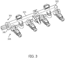
- Fig. 3 illustrates an example of the container under test 105 according to one embodiment.
- the container under test 105 may include various types of containers with at least one sealable connection.
- the container under test 105 may include various containers with a sealable connection, such as, for example, a pipe with a cap or plug; a tube with a sealable fitting, a bottle with a cap, plug or cork; a drum with a lid, and the like.
- the container under test 105 may be formed from various materials and constructed in various ways.
- the container under test 105 may be formed of plastic, metal, polymer, or a combination of these materials. Embodiments listed herein are particularly suitable for testing the tightness of various types of containers with zero or very low leak rates.
- the container under test 105 is a fuel rail assembly 305.
- the fuel rail assembly 305 is an automotive component that supplies fuel (e.g., gasoline) to cylinders of an engine of a vehicle. Due to strict manufacturing standards, the fuel rail assembly 305 is constructed to have zero or very low leak rates.
- the fuel rail assembly 305 may be formed from various materials and constructed in various ways. For example, the fuel rail assembly 305 may be formed of plastic, metal, polymer, or a combination of these materials.
- the fuel rail assembly 305 includes an end cap 310 and a rail tube 325. The end cap 310 is directly coupled to one end 315 of the fuel rail assembly 305. A similar end cap (not illustrated) may be included on an opposite end 320 of the fuel rail assembly 305.
- the end cap 310 is coupled to the fuel rail assembly 305 during manufacture.
- the end cap 310 may be coupled to the fuel rail assembly 305 in various ways including a welded joint, a glued (e.g., epoxied) joint, crimp joint with elastomer sealing element, and the like.
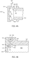
- Fig. 4A illustrates a junction 405 between the rail tube 325 and the end cap 310 prior to coupling.
- the rail tube 325 and the end cap 310 may form an airtight seal when coupled at the junction 405 to form the fuel rail assembly 305 illustrated in Fig. 3 .
- the junction 405 is formed by a plurality of weld surfaces 410. During assembly, the weld surfaces 410 are pressed together and fused by welding or glue.
- the end cap 310 may include one or more inner seal surfaces 415 and one or more outer seal surfaces 420.
- the inner seal surfaces 415 may press against an interior circumferential surface 425 of the rail tube 325.
- the inner seal surfaces 415 may be cylindrical to match the shape of the rail tube 325.
- the outer seal surfaces 420 may press against an exterior circumferential surface 430 of the rail tube 325 and may also be cylindrical to match the shape of the rail tube 325.
- the outer seal surfaces 420 may press against and couple to a stop surface 435 of the rail tube 325.
- Flash traps 440 may be located near the weld surfaces 410.
- the flash traps 440 may be designed to collect sealing material (e.g., welding flash, glue, epoxy, and the like) from the junction 405 when coupled.
- Fig. 4B illustrates a portion of the junction 405 after connection of the rail tube 325 and the end cap 310.
- the junction 405 includes sealing material 450 deposited in locations including at least the flash traps 440.
- the sealing material 450 may be a byproduct of the coupling process.
- the sealing material 450, the inner seal surfaces 415, the outer seal surfaces 420, or a combination of the aforementioned may create a trapped volume 455 or multiple trapped volumes within the fuel rail assembly 305.
- the trapped volume 455 may be formed by sealing material 450 that completely or partially isolates the trapped volume 455 from an interior volume 460 of the fuel rail assembly 305.
- the trapped volume 455 may be isolated from the interior volume 460 such that an airtight seal is formed between the trapped volume 455 and the interior volume 460.
- the trapped volume 455 may be partially isolated such that an internal leak (e.g., a pinhole-sized pathway) 465 forms between the trapped volume 455 and the interior volume 460.
- Fig. 5 illustrates a sealable junction 500 according to one embodiment.
- the sealable junction 500 may be used for connections of the container under test 105, the fuel rail assembly 305, or another type of container.
- the sealable junction 500 is formed, at least in part, by one or more O-rings and a crimped connection.
- a container body 505 e.g., a rail tube
- a lid 510 e.g., an end cap
- the lid 510 is affixed to the container body 505 via a crimp joint 515.
- a first O-ring 520 and a second O-ring 525 are positioned between the container body 505 and the lid 510.
- the first O-ring 520 provides a first seal between an interior volume 560 and outside of the container body 505.
- the second O-ring 525 provides a second seal between the interior volume 560 and the outside of the container body 505.
- the first O-ring 520 and the second O-ring 525 provide a dual sealing mechanism in which either of the first O-ring 520 or the second O-ring 525 may be sufficient to provide an airtight seal between the interior volume 560 and the outside of the container body 505.
- combination of the first O-ring 520 and the second O-ring 525 generally provides a seal with lower leak rates than a seal with a single O-ring.
- a trapped volume 555 may be formed between the first O-ring 520, the second O-ring 525, the container body 505, and the lid 510.
- the trapped volume 555 may be isolated from the interior volume 560 (e.g., when the first O-ring 520 forms an airtight seal).
- the trapped volume 555 may be isolated from the outside of the container body 505 (e.g., when the second O-ring 525 forms an airtight seal).
- the first O-ring 520 does not provide an airtight seal between the interior volume 560 and the trapped volume 555.
- an internal leak 565 may exist between the interior volume 560 and the outside of the container body 505.
- the trapped volume 455, 555 and the interior volume 460, 560 may equalize in pressure due to the lack of an airtight seal.
- the testing gas may leak into the trapped volume 455, 555.
- the testing gas may leak into the trapped volume 455, 555 until the gas pressure in the trapped volume 455, 555 equalizes with the gas pressure in the interior volume 460, 560.
- the exchange of testing gas and the equalization of pressure happens over different time periods.
- Figs. 6A and 6B illustrate a method 600 of testing the tightness of the container under test 105.
- the method 600 includes a two-part test for testing containers under test 105 that may or may not include the trapped volume 455, 555 and the internal leak 465, 565.
- Fig. 6A illustrates a first part of the method 600 of tightness testing designed to distinguish containers with low leak rates from containers with either high leak rates or those with the trapped volume 455, 555 and the internal leak 465, 565.
- the first part of the method 600 is designed to quickly determine whether the container under test 105 is within compliance (e.g., whether the container under test 105 meets or exceeds higher than required quality standards of tightness).
- Fig. 6B illustrates a second part of the method 600 of testiness testing designed to test containers with moderate leak rates and those with the trapped volume 455, 555 and the internal leak 465, 565.
- the second part of the method 600 is designed to determine whether the container under test 105 has a leak rate under a maximum allowable leak rate, and thus within compliance.
- the controller 120 identifies the container under test 105 as compliant.
- the container under test 105 is connected to the gas supply section 110 (block 605). Once connected, the container under test 105 is filled with testing gas from the gas supply section 110.
- the controller 120 controls the filling of the container under test 105 to a predetermined test pressure (block 610). For example, the container under test 105 is filled until the testing gas reaches the predetermined pressure as indicated by the pressure sensor 225. In other embodiments, the container under test 105 is filled for a first fill period determined by the controller 120 (e.g., based on mechanical, electronic, or programmed timers within the controller 120).
- the controller 120 disconnects the supply of testing gas (e.g., via an actuator) and begins stabilizing the container under test 105 (block 615).
- the container under test 105 is stabilized for a period of time so that the temperature of the testing gas inside the container under test 105 equalizes (e.g., approach an approximately steady-state condition) with the container under test 105 and the ambient temperature.
- the controller 120 monitors the temperature sensor 230, the pressure sensor 225, or both to determine when the container under test 105 is stabilized.
- the controller 120 may determine that stabilization has occurred when the measured temperature reaches a temperature set point (e.g., equals the ambient temperature) and when the measured pressure reaches a pressure set point.
- the controller 120 initiates a counter and determines that the container under test 105 is stabilized after a first stabilization period.
- the controller 120 determines whether the first stabilization period has expired (block 620). When the first stabilization period has not ended, the controller 120 continues to stabilize the container under test 105.
- the controller 120 measures the leak rate of the container under test 105 (block 625). Measuring the leak rate may include monitoring the pressure sensor 225 and in some embodiments, the temperature sensor 230, to determine a change in pressure of the testing gas inside the container under test 105. The leak rate is measured until the controller 120 determines when the first measuring period is expired (block 630). Measuring the first leak rate of the container under test 105 over the first measuring period may include performing a fast leak rate test as compared to the second measuring period as described below. When the first measuring period expires, the controller 120 determines whether the leak rate is below a first threshold (block 635).
- the container under test 105 completes the method 600 of testing the tightness of the container under test 105 and is determined to be in compliance (i.e., tolerance) (block 640). Conversely, when the leak rate is above the first threshold, the controller 120 performs the second part of the method 600 of testing the tightness of the container under test 105 to determine whether it is in compliance (block 645).
- the controller 120 optionally vents the testing gas from container under test 105 via the gas vent section 115 (block 650).
- the testing gas is not vented between the first part of the method 600 and the second part of the method 600.
- testing gas is added via the gas supply section 110 until the pressure sensor 225 indicates that the gas pressure is adequate for the second part of the method 600.
- the container under test 105 is filled with testing gas via the gas supply section 110 (block 655).
- the controller 120 determines when to stop filling the container under test 105 with testing gas. Similar to the first part of the method 600, the controller 120 may perform this determination based on the pressure sensor 225 or based on a predetermined fill time.
- the controller 120 stabilizes the container under test 105 (block 660). To stabilize the container under test 105, in some embodiments, the controller 120 waits a predetermined amount of time (block 665), while in other embodiments, the controller 120 measures a pressure and temperature of the container under test 105 or the pressure and temperature of the testing gas to determine when the container under test 105 is stabilized.
- the controller 120 measures the leak rate of the container under test 105 (block 670).
- the controller 120 measures the leak rate over a second measuring period.
- the second measuring period may occur over a longer period of time than the first measuring period from the first part of the method 600 and, in this way, may be considered a slow leak rate test as compared to the first part of the method 600.
- the second part of the method 600 takes a longer amount of time than the first part of the method 600.
- the controller 120 determines whether the second measuring period has expired (block 675). When the second measuring period has expired, the controller 120 determines whether the second leak rate is below a second threshold (block 680).
- the second threshold may be a value of a maximum allowable leak rate that conform with manufacturing or quality standards for the particular container under test 105.
- the container under test 105 When the second leak rate is below the second threshold, the container under test 105 is determined to be in compliance and therefore, passes the second part of the method 600 (block 685). Conversely, when the second leak rate is above the second threshold, the container under test 105 is determined to be out of compliance, and therefore fails the second part of the method 600 (block 680). As a consequence, the container under test 105 is either scrapped or reworked and retested. In this case, the container under test 105 may be inspected for leaks using a bubble test or other leak detection method. When a leak is detected, the container under test 105 may be, in some cases, repaired and then subjected to retesting via the method 600.
- the first part of the method 600 is designed to pass containers that do not contain the trapped volume 455, 555 and the internal leak 465, 565.
- the measuring stage may indicate that the leak rate of the container under test 105 is greater than in actuality.
- the controller 120 may measure a drop in pressure of the interior volume 460, 560 caused from testing gas leaking through to the trapped volume 455, 555. This may falsely indicate a leak rate above the maximum allowable leak rate.
- the container under test 105 is tested using the second part of the method 600, which provides additional testing time to allow the pressure of the testing gas in the interior volume 460, 560 and the trapped volume 455, 555 to equalize.
- the container under test 105 is tested using the second part of the method 600, which provides additional testing time to allow the pressure of the testing gas in the interior volume 460, 560 and the trapped volume 455, 555 to equalize.
- only containers with moderate leak rates or those with the interior volume 460, 560 and the internal leak 465, 565 are subject to longer measuring and stabilization periods to accurately determine whether the actual leak rate is in compliance with quality standards.
- the measured leak rate indicates leakage from the interior volume 460, 560 to the outside of the container under test 105.
- the leak rate is not influenced by the trapped volume 455, 555 and the measured leak rate is a more accurate indication of the actual leak rate of the container under test 105.
- the measured leak rate of a container without the trapped volume 455, 555 may be lower than a container with the trapped volume 455, 555 even when they have the same actual leak rate. Therefore, the second part of the method 600 is adapted to test the container with the trapped volume 455, 555 and may determine that the container with the trapped volume 455, 555 is compliant even when it did not pass the first part of the method 600.
- the first part of the method 600 has significantly shorter measuring periods and may have significantly shorter stabilizing periods. This is because containers with low leak rates are readily distinguished in a short period of time. In this way, containers that pass the first part of the method 600 are tested quickly and therefore, testing a batch of containers that includes at least some containers that pass the first part of the method 600 is faster than if all of the containers are tested with the second part of the method 600.
- Fig. 7 illustrates an example of a graph of pressure versus time for the container under test 105 during the first part of the method 600 (See Fig. 6A ).
- the pressure of the testing gas inside the container under test 105 is plotted on the y-axis. Time is plotted on the x-axis.
- the first part of the method 600 includes four distinct stages: filling period (represented by t 1 ), stabilizing period (represented by t 2 ), measuring period (represented by t 3 ), and venting period (represented by t 4 ).
- the pressure of the testing gas increases as testing gas is supplied to the container under test 105.
- the stabilizing stage the pressure decreases as the temperature of the testing gas stabilizes to a temperature of the container under test 105.
- the controller 120 measures the pressure decay (i.e., pressure drop) inside the container under test 105 over the measuring stage as indicated by dashed lines 705. The controller 120 may then store the measured pressure decay in the memory 210. During the venting stage, the controller 120 vents the container under test 105 via the gas vent section 115 and the pressure of the testing gas is quickly reduced.
- the controller 120 determines a leak rate based on the pressure decay during the measuring stage.
- the controller 120 calculates the leak rate based on a predetermined internal volume of the container under test 105 that is preprogrammed into the memory 210.
- the leak rate that is determined by the controller 120 may include both a relatively constant leak rate from the interior volume 460, 560 to the outside of the container under test 105 and a transitory leak rate from the interior volume 460, 560 to the trapped volume 455, 555 of the container under test 105.
- the container under test 105 passes the first part of the method 600.
- the first threshold is set at a value substantially less than a maximum value of allowable leak rate. For example, when testing the fuel rail assembly 305, the first threshold may be set to 1.0 standard cubic centimeter per minute (SCCM) or less even when the maximum allowable leak rate may be 1.5 SCCM or greater. As a consequence, when containers pass the first part of the method 600, the containers are considered low-leak rate containers.
- Fig. 8 illustrates an example of a graph of pressure versus time for the container under test 105 with the trapped volume 455, 555 and the internal leak 465, 565 during the second part of the method 600 (See Fig. 6B ).
- Fig. 8 is similar to the graph depicted in Fig. 7 with similar stages and behavior of the testing gas and the container under test 105.
- the second test includes a measuring stage (e.g., time period between t 2 and t 3 ) that is substantially longer than the measuring stage in the first part of the method 600.
- the pressure of the testing gas drops more rapidly in the early part than in the later part of the measuring stage. The steeper drop in pressure is due to the internal leak 465, 565.
- the controller 120 measures the pressure decay during the measuring stage and therefore, may generate the curve 805. Based on the behavior of this curve 805, the controller 120 determines the actual leak rate of the container under test 105.
- the second part of the method 600 may take substantially longer, but may be more accurate, than the first part of the method 600.
- the controller 120 may set the second threshold at a maximum allowable leak rate for compliance during the second part of the method 600. For example, the second threshold may be set at a value of 1.5 SCCM when the first threshold is set at a value of 1.0 SCCM for testing the fuel rail assembly 305.
Landscapes
- Engineering & Computer Science (AREA)
- Physics & Mathematics (AREA)
- General Physics & Mathematics (AREA)
- Chemical & Material Sciences (AREA)
- Combustion & Propulsion (AREA)
- Mechanical Engineering (AREA)
- General Engineering & Computer Science (AREA)
- Examining Or Testing Airtightness (AREA)
Description
- Embodiments of the invention relate to methods and systems of measuring leak rates in closed containers. In
DE 100 06 185 C1EP 0 974 826 A2 a method of detecting a leak in a fuel supply system of a combustion engine with a common rail system is disclosed. For detecting a leak a driving signal of a high pressure pump while coasting is compared with at least on threshold and/or it is checked whether a pressure is dropping as expected. - The invention provides a method and a system for testing a closed container for tightness as recited in the independent claims. Advantageous embodiments are set out in the dependent claims. One embodiment provide a method of testing tightness of a closed volume for a plurality of containers (e.g., fuel rails). In one example, the method involves performing a low-leakage rate test to detect containers with low-leakage rates. The low-leakage rate test is performed at a leakage rate substantially below an allowable leakage rate (i.e., within acceptable tolerances). Containers that fail the low-leakage rate test undergo a leakage rate test involving longer testing times and a leakage rate near the allowable leakage rate. Containers that pass the low-leakage rate test do not need to be tested with the slower, high-leakage rate testing.
- One embodiment provides a method of testing a closed container for tightness including connecting the closed container to a gas supply and filing the closed container with a testing gas from the gas supply. A controller measures a first leak rate of the closed container over a first period of time. When the first leak rate is less than a first threshold, the controller identifies the closed container as compliant. When the first leak rate is greater than the first threshold, the controller measures a second leak rate of the closed container over a second period of time. When the second leak rate is greater than a second threshold, the controller identifies the closed container as noncompliant, and when the second leak rate is less than the second threshold, the controller identifies the closed container as compliant.
- Another embodiment provides a system for testing a closed container for tightness. The system includes a gas supply section, a pressure sensor, and a controller including an electronic processor and a memory. The controller is configured to fill the closed container with a testing gas from the gas supply and measure a first leak rate of the closed container over a first period of time. When the first leak rate is greater than a first threshold, the controller identifies the closed container as compliant. When the first leak rate is less than the first threshold, the controller fills the closed container with the testing gas from the gas supply and measures a second leak rate of the closed container over a second period of time. When the leak rate is greater than a second threshold, the controller identifies the closed container as noncompliant. When the leak rate is less than the second threshold, the controller identifies the closed container as compliant.
- Other aspects of various embodiments will become apparent by consideration of the detailed description and accompanying drawings.
-
-
Fig. 1 is a block diagram of a testing station for tightness testing of a device under test according to one embodiment. -
Fig. 2 is a block diagram of a controller for the testing station ofFig. 1 according to one embodiment. -
Fig. 3 is a perspective view of the device under test ofFig. 1 according to one embodiment. -
Fig. 4A is a cross-sectional view of a rail tube and end cap for the device under test ofFig. 1 according to one embodiment. -
Fig. 4B is a cross-sectional view of the rail tube and the end cap ofFig. 4A after assembly according to one embodiment. -
Fig. 5 is a cross-sectional view of a dual O-ring seal of the device under test ofFig. 1 according to one embodiment. -
Figs. 6A and6B are flowcharts that illustrate a method of tightness testing of the device under test ofFig. 1 according to one embodiment. -
Fig. 7 is a graph of pressure versus time for a first part of the method of tightness testing ofFigs. 6A and6B according to one example. -
Fig. 8 is a graph of pressure versus time for a second part of the method of tightness testing ofFigs. 6A and6B according to another example. - Before any embodiments are explained in detail, it is to be understood that the invention is not limited in its application to the details of construction and the arrangement of components set forth in the following description or illustrated in the following drawings. The invention is capable of other embodiments and of being practiced or of being carried out in various ways.
- It should be noted that a plurality of hardware and software based devices, as well as a plurality of different structural components may be used to implement various embodiments. In addition, it should be understood that certain embodiments may include hardware, software, and electronic components or modules that, for purposes of discussion, may be illustrated and described as if certain components were implemented solely in hardware. However, one of ordinary skill in the art, based on a reading of this detailed description, would recognize that, in at least one embodiment, aspects may be implemented in software (e.g., stored on non-transitory computer-readable medium) executable by one or more processors. Accordingly, it should be noted that a plurality of hardware and software based devices, as well as a plurality of different structural components may be utilized to implement various embodiments. For example, "control units" and "controllers" described in the specification may include one or more electronic processors, one or more memory modules including non-transitory computer-readable medium, one or more input/output interfaces, and various connections (e.g., a system bus, conductive tracks, wires, and the like) connecting the components.
-
Fig. 1 illustrates atesting station 100 for a container under test (e.g., a closed container) 105 according to some embodiments. In some embodiments, thetesting station 100 performs a quality check for the container undertest 105 and is implemented after manufacture of the container undertest 105. Thetesting station 100 may be incorporated in an assembly line implementing a manufacturing process for the container undertest 105. For example, the container undertest 105 may enter thetesting station 100 via belt, track, conveyor, and the like. Once in thetesting station 100, the container undertest 105 is tested for tightness. In other words, the container undertest 105 is tested to determine a leak rate from inside the container undertest 105 to outside the container undertest 105. In some embodiments, after the container undertest 105 is tested, another container is brought into thetesting station 100 and the process repeats. In other embodiments, thetesting station 100 may test a single container. In yet other embodiments, multiple containers may be tested simultaneously by parallel processing equipment. - In the illustrative embodiment, the
testing station 100 includes, among other things, agas supply section 110, and agas vent section 115. In some embodiments, thegas supply section 110 and thegas vent section 115 share a mechanical connection to the container undertest 105. For example, thegas supply section 110 and thegas vent section 115 may both be connected and may use a single connection via tubes, hoses, pipes and the like. In other embodiments, during testing, thegas supply section 110 and thegas vent section 115 are separately coupled to the container undertest 105 with tubes, hoses, pipes, and the like via a mechanical connection such as, for example, a quick-disconnect fitting. In addition, thegas supply section 110 and thegas vent section 115 may be separately housed or may both be included in a single monolithic compartment or module. - The
gas supply section 110 includes a pathway for supplying testing gas to the container undertest 105. When coupled to the container undertest 105, thegas supply section 110 may pressurize the container undertest 105 with the testing gas. Thegas supply section 110 may also include storage (e.g., gas cylinders) for testing gas. Testing gas may include various types of gasses including noble gasses, nitrogen, or others. - The
gas vent section 115 includes a pathway for venting the testing gas. When coupled to the container undertest 105, thegas vent section 115 may remove the testing gas from the container undertest 105. The testing gas may be vented after testing is complete, before testing begins, or between a first part of the testing method and the second part of the testing method as described below. In some embodiments, thegas vent section 115 includes a vacuum pump (not illustrated) for removing the testing gas from the container undertest 105. - The
testing station 100 also includes acontroller 120. Thecontroller 120 is communicatively coupled to thegas supply section 110, thegas vent section 115, and the container undertest 105. For example, thecontroller 120 may have direct or indirect electrical connections with thegas supply section 110 and thegas vent section 115. During testing, thecontroller 120 may electrically connect to the container undertest 105 using a temporary electrical connection. For example, thecontroller 120 may be electrically connected to the container undertest 105 with cables, wires, and the like via a wire harness or plug-type connection. - As illustrated in
Fig. 2 , thecontroller 120 includes a plurality of electrical and electronic components that provide power, operation control, and protection to the components and modules within thecontroller 120. Thecontroller 120 includes, among other things, an electronic processor 205 (such as a programmable electronic microprocessor, microcontroller, or similar device), a memory 210 (e.g., non-transitory, machine readable memory), anoutput interface 215, and aninput interface 220. In other embodiments, thecontroller 120 includes additional, fewer, or different components. Thecontroller 120 may be implemented in several independent controllers each configured to perform specific functions or sub-functions. Additionally, thecontroller 120 may contain sub-modules that process inputs and outputs and perform related processes. - Components of the
controller 120 and associated systems are configured to implement, among other things, processes and methods described herein. For example, theelectronic processor 205 is communicatively coupled to thememory 210 and executes instructions which are capable of being stored on thememory 210. Theelectronic processor 205 is configured to retrieve frommemory 210 and execute instructions related the methods of operation of thetesting station 100. In some embodiments, theoutput interface 215 includes drivers, relays, switches, and the like to operate and control thegas supply section 110 and thegas vent section 115 based on instructions from theelectronic processor 205. - The
controller 120 is communicatively coupled to apressure sensor 225 and atemperature sensor 230. Thepressure sensor 225 and thetemperature sensor 230 may be electrically connected to thecontroller 120 via theinput interface 220. In this configuration, theinput interface 220 may include input terminals and input hardware- or software-based logic. The input logic detects and processes various input signals including pressure and temperature signals from sensors and electronic devices, such as, for example, resistive sensors, voltage controlled sensors, current controlled sensors, and the like. In particular, thecontroller 120 receives pressure and temperature signals from thepressure sensor 225 and thetemperature sensor 230 respectively. Thecontroller 120 inputs pressure and temperature readings either continuously or at intervals during testing and may perform the methods described herein based on the pressure and temperature readings. - The
pressure sensor 225 and thetemperature sensor 230 may be physically coupled to and uncoupled from the container undertest 105. For example, during testing, thepressure sensor 225 and thetemperature sensor 230 may be directly attached to the container undertest 105 via a testing apparatus (not shown). In other embodiments, thepressure sensor 225 and thetemperature sensor 230 may be located remotely from the container undertest 105. In such configurations, thepressure sensor 225 may measure pressure inside the container undertest 105 via tubing, piping, fittings, and/or hose connections. Similarly, thetemperature sensor 230 may measure temperature remotely using, for example, an infrared temperature sensor. - The
pressure sensor 225 is configured to measure gas pressure of the testing gas within the container undertest 105. Similarly, thetemperature sensor 230 is configured to measure temperature of the testing gas inside the container undertest 105, the temperature of the container undertest 105, or both. In some embodiments, thecontroller 120 uses the pressure and temperature readings to achieve steady-state testing conditions prior to measuring leak rates of the container undertest 105 as described below. -
Fig. 3 illustrates an example of the container undertest 105 according to one embodiment. In general, the container undertest 105 may include various types of containers with at least one sealable connection. For example, the container undertest 105 may include various containers with a sealable connection, such as, for example, a pipe with a cap or plug; a tube with a sealable fitting, a bottle with a cap, plug or cork; a drum with a lid, and the like. The container undertest 105 may be formed from various materials and constructed in various ways. For example, the container undertest 105 may be formed of plastic, metal, polymer, or a combination of these materials. Embodiments listed herein are particularly suitable for testing the tightness of various types of containers with zero or very low leak rates. - In the illustrated example, the container under
test 105 is afuel rail assembly 305. Thefuel rail assembly 305 is an automotive component that supplies fuel (e.g., gasoline) to cylinders of an engine of a vehicle. Due to strict manufacturing standards, thefuel rail assembly 305 is constructed to have zero or very low leak rates. Thefuel rail assembly 305 may be formed from various materials and constructed in various ways. For example, thefuel rail assembly 305 may be formed of plastic, metal, polymer, or a combination of these materials. Thefuel rail assembly 305 includes anend cap 310 and arail tube 325. Theend cap 310 is directly coupled to oneend 315 of thefuel rail assembly 305. A similar end cap (not illustrated) may be included on anopposite end 320 of thefuel rail assembly 305. Theend cap 310 is coupled to thefuel rail assembly 305 during manufacture. Theend cap 310 may be coupled to thefuel rail assembly 305 in various ways including a welded joint, a glued (e.g., epoxied) joint, crimp joint with elastomer sealing element, and the like. -
Fig. 4A illustrates ajunction 405 between therail tube 325 and theend cap 310 prior to coupling. For example, therail tube 325 and theend cap 310 may form an airtight seal when coupled at thejunction 405 to form thefuel rail assembly 305 illustrated inFig. 3 . In some embodiments, thejunction 405 is formed by a plurality of weld surfaces 410. During assembly, the weld surfaces 410 are pressed together and fused by welding or glue. Theend cap 310 may include one or more inner seal surfaces 415 and one or more outer seal surfaces 420. The inner seal surfaces 415 may press against an interiorcircumferential surface 425 of therail tube 325. The inner seal surfaces 415 may be cylindrical to match the shape of therail tube 325. Similarly, the outer seal surfaces 420 may press against an exteriorcircumferential surface 430 of therail tube 325 and may also be cylindrical to match the shape of therail tube 325. The outer seal surfaces 420 may press against and couple to astop surface 435 of therail tube 325. Flash traps 440 may be located near the weld surfaces 410. The flash traps 440 may be designed to collect sealing material (e.g., welding flash, glue, epoxy, and the like) from thejunction 405 when coupled. -
Fig. 4B illustrates a portion of thejunction 405 after connection of therail tube 325 and theend cap 310. Once sealed, thejunction 405 includes sealingmaterial 450 deposited in locations including at least the flash traps 440. The sealingmaterial 450 may be a byproduct of the coupling process. The sealingmaterial 450, the inner seal surfaces 415, the outer seal surfaces 420, or a combination of the aforementioned may create atrapped volume 455 or multiple trapped volumes within thefuel rail assembly 305. The trappedvolume 455 may be formed by sealingmaterial 450 that completely or partially isolates the trappedvolume 455 from aninterior volume 460 of thefuel rail assembly 305. For example, the trappedvolume 455 may be isolated from theinterior volume 460 such that an airtight seal is formed between thetrapped volume 455 and theinterior volume 460. In another example, the trappedvolume 455 may be partially isolated such that an internal leak (e.g., a pinhole-sized pathway) 465 forms between thetrapped volume 455 and theinterior volume 460. -
Fig. 5 illustrates asealable junction 500 according to one embodiment. Thesealable junction 500 may be used for connections of the container undertest 105, thefuel rail assembly 305, or another type of container. In the illustrative example, thesealable junction 500 is formed, at least in part, by one or more O-rings and a crimped connection. In particular, a container body 505 (e.g., a rail tube) is physically coupled to a lid 510 (e.g., an end cap). Thelid 510 is affixed to thecontainer body 505 via a crimp joint 515. A first O-ring 520 and a second O-ring 525 are positioned between thecontainer body 505 and thelid 510. The first O-ring 520 provides a first seal between aninterior volume 560 and outside of thecontainer body 505. The second O-ring 525 provides a second seal between theinterior volume 560 and the outside of thecontainer body 505. In this way, the first O-ring 520 and the second O-ring 525 provide a dual sealing mechanism in which either of the first O-ring 520 or the second O-ring 525 may be sufficient to provide an airtight seal between theinterior volume 560 and the outside of thecontainer body 505. As a consequence, combination of the first O-ring 520 and the second O-ring 525 generally provides a seal with lower leak rates than a seal with a single O-ring. - A trapped
volume 555 may be formed between the first O-ring 520, the second O-ring 525, thecontainer body 505, and thelid 510. The trappedvolume 555 may be isolated from the interior volume 560 (e.g., when the first O-ring 520 forms an airtight seal). Similarly, the trappedvolume 555 may be isolated from the outside of the container body 505 (e.g., when the second O-ring 525 forms an airtight seal). In some cases, the first O-ring 520 does not provide an airtight seal between theinterior volume 560 and the trappedvolume 555. This may occur in containers where the first O-ring 520 is not properly seated or twisted, when the first O-ring 520 or sealing surface has defects, when foreign matter enters thesealable junction 500, and like conditions. In such cases, aninternal leak 565 may exist between theinterior volume 560 and the outside of thecontainer body 505. - In the examples illustrated in
Figs. 4B and5 , the trappedvolume interior volume interior volume volume volume volume interior volume internal leak interior volume internal leak trapped volume interior volume -
Figs. 6A and6B illustrate a method 600 of testing the tightness of the container undertest 105. The method 600 includes a two-part test for testing containers undertest 105 that may or may not include the trappedvolume internal leak Fig. 6A illustrates a first part of the method 600 of tightness testing designed to distinguish containers with low leak rates from containers with either high leak rates or those with the trappedvolume internal leak test 105 is within compliance (e.g., whether the container undertest 105 meets or exceeds higher than required quality standards of tightness). In other words, when the first part of the method 600 indicates a low leak rate, thecontroller 120 identifies the container undertest 105 as compliant. Conversely,Fig. 6B illustrates a second part of the method 600 of testiness testing designed to test containers with moderate leak rates and those with the trappedvolume internal leak test 105 has a leak rate under a maximum allowable leak rate, and thus within compliance. In other words, when the second part of the method 600 indicates a low leak rate, thecontroller 120 identifies the container undertest 105 as compliant. - In the first part of the method 600 as illustrated in
Fig. 6A , the container undertest 105 is connected to the gas supply section 110 (block 605). Once connected, the container undertest 105 is filled with testing gas from thegas supply section 110. In some embodiments, thecontroller 120 controls the filling of the container undertest 105 to a predetermined test pressure (block 610). For example, the container undertest 105 is filled until the testing gas reaches the predetermined pressure as indicated by thepressure sensor 225. In other embodiments, the container undertest 105 is filled for a first fill period determined by the controller 120 (e.g., based on mechanical, electronic, or programmed timers within the controller 120). When the container undertest 105 is filled with testing gas, thecontroller 120 disconnects the supply of testing gas (e.g., via an actuator) and begins stabilizing the container under test 105 (block 615). The container undertest 105 is stabilized for a period of time so that the temperature of the testing gas inside the container undertest 105 equalizes (e.g., approach an approximately steady-state condition) with the container undertest 105 and the ambient temperature. In some embodiments, thecontroller 120 monitors thetemperature sensor 230, thepressure sensor 225, or both to determine when the container undertest 105 is stabilized. For example, thecontroller 120 may determine that stabilization has occurred when the measured temperature reaches a temperature set point (e.g., equals the ambient temperature) and when the measured pressure reaches a pressure set point. In other embodiments, thecontroller 120 initiates a counter and determines that the container undertest 105 is stabilized after a first stabilization period. In this embodiment, thecontroller 120 determines whether the first stabilization period has expired (block 620). When the first stabilization period has not ended, thecontroller 120 continues to stabilize the container undertest 105. - Next, the
controller 120 measures the leak rate of the container under test 105 (block 625). Measuring the leak rate may include monitoring thepressure sensor 225 and in some embodiments, thetemperature sensor 230, to determine a change in pressure of the testing gas inside the container undertest 105. The leak rate is measured until thecontroller 120 determines when the first measuring period is expired (block 630). Measuring the first leak rate of the container undertest 105 over the first measuring period may include performing a fast leak rate test as compared to the second measuring period as described below. When the first measuring period expires, thecontroller 120 determines whether the leak rate is below a first threshold (block 635). When the leak rate is below the first threshold, the container undertest 105 completes the method 600 of testing the tightness of the container undertest 105 and is determined to be in compliance (i.e., tolerance) (block 640). Conversely, when the leak rate is above the first threshold, thecontroller 120 performs the second part of the method 600 of testing the tightness of the container undertest 105 to determine whether it is in compliance (block 645). - In the second part of the method 600, the
controller 120 optionally vents the testing gas from container undertest 105 via the gas vent section 115 (block 650). In some embodiments, the testing gas is not vented between the first part of the method 600 and the second part of the method 600. When not vented, testing gas is added via thegas supply section 110 until thepressure sensor 225 indicates that the gas pressure is adequate for the second part of the method 600. In either case, the container undertest 105 is filled with testing gas via the gas supply section 110 (block 655). Thecontroller 120 determines when to stop filling the container undertest 105 with testing gas. Similar to the first part of the method 600, thecontroller 120 may perform this determination based on thepressure sensor 225 or based on a predetermined fill time. Once the container undertest 105 is filled, thecontroller 120 stabilizes the container under test 105 (block 660). To stabilize the container undertest 105, in some embodiments, thecontroller 120 waits a predetermined amount of time (block 665), while in other embodiments, thecontroller 120 measures a pressure and temperature of the container undertest 105 or the pressure and temperature of the testing gas to determine when the container undertest 105 is stabilized. - Once the container under
test 105 is stabilized, thecontroller 120 measures the leak rate of the container under test 105 (block 670). Thecontroller 120 measures the leak rate over a second measuring period. The second measuring period may occur over a longer period of time than the first measuring period from the first part of the method 600 and, in this way, may be considered a slow leak rate test as compared to the first part of the method 600. As a consequence, the second part of the method 600 takes a longer amount of time than the first part of the method 600. Thecontroller 120 determines whether the second measuring period has expired (block 675). When the second measuring period has expired, thecontroller 120 determines whether the second leak rate is below a second threshold (block 680). The second threshold may be a value of a maximum allowable leak rate that conform with manufacturing or quality standards for the particular container undertest 105. When the second leak rate is below the second threshold, the container undertest 105 is determined to be in compliance and therefore, passes the second part of the method 600 (block 685). Conversely, when the second leak rate is above the second threshold, the container undertest 105 is determined to be out of compliance, and therefore fails the second part of the method 600 (block 680). As a consequence, the container undertest 105 is either scrapped or reworked and retested. In this case, the container undertest 105 may be inspected for leaks using a bubble test or other leak detection method. When a leak is detected, the container undertest 105 may be, in some cases, repaired and then subjected to retesting via the method 600. - Due to the short measuring period, the first part of the method 600 is designed to pass containers that do not contain the trapped
volume internal leak test 105 contains a trappedvolume test 105 is greater than in actuality. For example, when the container undertest 105 contains the trappedvolume internal leak controller 120 may measure a drop in pressure of theinterior volume volume test 105 is tested using the second part of the method 600, which provides additional testing time to allow the pressure of the testing gas in theinterior volume volume interior volume internal leak - Conversely, when the container under
test 105 does not include atrapped volume volume interior volume interior volume test 105. As a consequence, the leak rate is not influenced by the trappedvolume test 105. As such, in the first part of the method 600, the measured leak rate of a container without the trappedvolume volume volume volume - Often, many containers will be found compliant under the first part of the method 600 and will not need to be tested using the second part of the method 600. This shortens overall testing times, since the first part of the method 600 is performed faster than the second part of the method. In particular, the first part of the method 600 has significantly shorter measuring periods and may have significantly shorter stabilizing periods. This is because containers with low leak rates are readily distinguished in a short period of time. In this way, containers that pass the first part of the method 600 are tested quickly and therefore, testing a batch of containers that includes at least some containers that pass the first part of the method 600 is faster than if all of the containers are tested with the second part of the method 600.
-
Fig. 7 illustrates an example of a graph of pressure versus time for the container undertest 105 during the first part of the method 600 (SeeFig. 6A ). The pressure of the testing gas inside the container undertest 105 is plotted on the y-axis. Time is plotted on the x-axis. The first part of the method 600 includes four distinct stages: filling period (represented by t1), stabilizing period (represented by t2), measuring period (represented by t3), and venting period (represented by t4). During the filling stage, the pressure of the testing gas increases as testing gas is supplied to the container undertest 105. During the stabilizing stage, the pressure decreases as the temperature of the testing gas stabilizes to a temperature of the container undertest 105. As a consequence, adiabatic effects that may influence the measuring stage are dissipated in the stabilization stage. Once the temperatures of the testing gas and the container undertest 105 equalize, thecontroller 120 measures the pressure decay (i.e., pressure drop) inside the container undertest 105 over the measuring stage as indicated by dashedlines 705. Thecontroller 120 may then store the measured pressure decay in thememory 210. During the venting stage, thecontroller 120 vents the container undertest 105 via thegas vent section 115 and the pressure of the testing gas is quickly reduced. - Since, the pressure decay is proportional to the leak rate, the
controller 120 determines a leak rate based on the pressure decay during the measuring stage. Thecontroller 120 calculates the leak rate based on a predetermined internal volume of the container undertest 105 that is preprogrammed into thememory 210. The leak rate that is determined by thecontroller 120 may include both a relatively constant leak rate from theinterior volume test 105 and a transitory leak rate from theinterior volume volume test 105. When a combined amount of leak rate both from the leak rate from theinterior volume test 105 and from the leak rate from theinterior volume volume test 105 passes the first part of the method 600. The first threshold is set at a value substantially less than a maximum value of allowable leak rate. For example, when testing thefuel rail assembly 305, the first threshold may be set to 1.0 standard cubic centimeter per minute (SCCM) or less even when the maximum allowable leak rate may be 1.5 SCCM or greater. As a consequence, when containers pass the first part of the method 600, the containers are considered low-leak rate containers. -
Fig. 8 illustrates an example of a graph of pressure versus time for the container undertest 105 with the trappedvolume internal leak Fig. 6B ).Fig. 8 is similar to the graph depicted inFig. 7 with similar stages and behavior of the testing gas and the container undertest 105. However, the second test includes a measuring stage (e.g., time period between t2 and t3) that is substantially longer than the measuring stage in the first part of the method 600. As illustrated by thecurve 805, the pressure of the testing gas drops more rapidly in the early part than in the later part of the measuring stage. The steeper drop in pressure is due to theinternal leak volume interior volume controller 120 measures the pressure decay during the measuring stage and therefore, may generate thecurve 805. Based on the behavior of thiscurve 805, thecontroller 120 determines the actual leak rate of the container undertest 105. As a consequence, the second part of the method 600 may take substantially longer, but may be more accurate, than the first part of the method 600. As a consequence, thecontroller 120 may set the second threshold at a maximum allowable leak rate for compliance during the second part of the method 600. For example, the second threshold may be set at a value of 1.5 SCCM when the first threshold is set at a value of 1.0 SCCM for testing thefuel rail assembly 305. - Thus, certain embodiments provide, among other things, a system and method for testing the tightness of a container using a two-part test. Features and advantages of various embodiments are set forth in the following claims.
Claims (19)
- A method (600) of testing a closed container (105, 305) for tightness, the method comprising:connecting (605) the closed container (105, 305) to a gas supply;filling (610) the closed container (105, 305) with a testing gas from the gas supply;measuring (625), by a controller, a first leak rate of the closed container (105, 305) over a first period of time (630);when the first leak rate is less than a first threshold (635), identifying (640) the closed container (105, 305) as compliant;when the first leak rate is greater than the first threshold (645),measuring (670) a second leak rate of the closed container (105, 305) over a second period of time (675);when the second leak rate is greater than a second threshold (680), identifying (690) the closed container (105, 305) as noncompliant; andwhen the second leak rate is less than the second threshold (680), identifying (685) the closed container (105, 305) as compliant;characterized bystabilizing (615) the closed container (105, 305) to a first gas pressure set point and a first temperature set point prior to measuring (625) the first leak rate.
- The method (600) of claim 1, the method (600) further comprising: stabilizing (660) the closed container (105, 305) to a second gas pressure set point and a second temperature set point prior to measuring (670) the second leak rate.
- The method (600) of claim 1, the method (600) further comprising: stabilizing (615) the closed container (105, 305) for a first stabilization period (620) prior to measuring (625) the first leak rate.
- The method (600) of claim 3, the method (600) further comprising: stabilizing (660) the closed container (105, 305) for a second stabilization period (665) prior to measuring (670) the second leak rate.
- The method (600) of claim 4, wherein stabilizing (660) the closed container (105, 305) for the second stabilization period (665) occurs over an amount of time that is greater than the first stabilization period (620).
- The method (600) of claim 1, wherein measuring (625) the first leak rate of the closed container (105, 305) over the first period of time (630) includes performing a fast leak rate test, which is fast compared to the second period of time (675).
- The method (600) of claim 1, wherein measuring (670) the second leak rate of the closed container (105, 305) over the second period of time (675) includes performing a slow leak rate test, which is slow compared to the first period of time (630).
- The method (600) of claim 1, wherein measuring (670) the second leak rate of the closed container (105, 305) over the second period of time (675) occurs over a period of time that is greater than the first period of time (630).
- The method (600) of claim 1, wherein identifying (690) the closed container (105, 305) as noncompliant when the second leak rate is greater than the second threshold (680) is performed with the second threshold (680) being greater than the first threshold (635).
- The method (600) of claim 1, wherein identifying (640) the closed container (105, 305) as compliant when the first leak rate is less than the first threshold (635) occurs when the closed container (105, 305) does not include an internal leak.
- The method (600) of claim 1, wherein identifying (685) the closed container (105, 305) as compliant when the second leak rate is less than the second threshold (680) occurs when the closed container (105, 305) includes an internal leak.
- The method (600) of claim 1, wherein measuring (625) the first leak rate of the closed container (105, 305) over the first period of time (630) is performed by measuring a change in gas pressure of the testing gas over the first period of time (630).
- The method (600) of claim 1, wherein measuring (670) the second leak rate of the closed container (105, 305) over the second period of time (675) is performed by measuring a change in gas pressure of the testing gas over the second period of time (675).
- A system (100) for testing a closed container (105, 305) for tightness, the system (100) comprising:a gas supply section (110);a pressure sensor (225);a controller (120) including an electronic processor (205) and a memory (210), the controller (120) configured to fill the closed container (105, 305) with a testing gas from the gas supply (110);measure a first leak rate of the closed container (105, 305) over a first period of time;when the first leak rate is less than a first threshold, identify the closed container (105, 305) as compliant;when the first leak rate is greater than the first threshold,fill the closed container (105, 305) with the testing gas from the gas supply (110);measure a second leak rate of the closed container (105, 305) over a second period of time;when the second leak rate is greater than a second threshold, identify the closed container (105, 305) as noncompliant; andwhen the leak rate is less than the second threshold, identify the closed container (105, 305) as compliant;characterized in thatthe controller (120) is configured to stabilize the closed container (105, 305) for a first stabilization period prior to measuring the first leak rate.
- The system (100) of claim 14, further comprising:
a gas vent section (115) configured to vent the testing gas from the closed container (105, 305) between when the first leak rate and the second leak rate are measured. - The system (100) of claim 14, wherein the controller (120) is configured to
stabilize the closed container (105, 305) for a second stabilization period prior to measuring the second leak rate. - The system (100) of claim 16, wherein the first stabilization period is shorter than the second stabilization period.
- The system (100) of claim 14, wherein the first period of time is shorter than the second period of time.
- The system (100) of claim 14, wherein the first threshold is less than the second threshold.
Applications Claiming Priority (2)
| Application Number | Priority Date | Filing Date | Title |
|---|---|---|---|
| US15/061,540 US10067027B2 (en) | 2016-03-04 | 2016-03-04 | Test methodology to reduce false rejections and increase number of containers tested for tightness |
| PCT/EP2017/053895 WO2017148741A1 (en) | 2016-03-04 | 2017-02-21 | Test methodology to reduce false rejections and increase number of containers tested for tightness |
Publications (2)
| Publication Number | Publication Date |
|---|---|
| EP3423803A1 EP3423803A1 (en) | 2019-01-09 |
| EP3423803B1 true EP3423803B1 (en) | 2021-12-22 |
Family
ID=58489286
Family Applications (1)
| Application Number | Title | Priority Date | Filing Date |
|---|---|---|---|
| EP17715630.4A Active EP3423803B1 (en) | 2016-03-04 | 2017-02-21 | Test methodology to reduce false rejections and increase number of containers tested for tightness |
Country Status (5)
| Country | Link |
|---|---|
| US (1) | US10067027B2 (en) |
| EP (1) | EP3423803B1 (en) |
| CN (1) | CN108700488B (en) |
| BR (1) | BR112018016698B1 (en) |
| WO (1) | WO2017148741A1 (en) |
Families Citing this family (6)
| Publication number | Priority date | Publication date | Assignee | Title |
|---|---|---|---|---|
| CA2961453A1 (en) * | 2014-09-30 | 2016-04-07 | Ft System S.R.L. | Group and method for measuring the pressure in closed containers |
| DE102017222308A1 (en) * | 2017-12-08 | 2019-06-13 | Inficon Gmbh | Method for leak testing with a foil chamber with ventilated measuring volume |
| CN110426197B (en) * | 2019-09-17 | 2024-07-09 | 思达耐精密机电(常熟)有限公司 | Device for verifying durability of oil seal products in batches |
| US11611740B2 (en) * | 2020-04-10 | 2023-03-21 | Viavi Solutions Inc. | Signal leakage monitoring based quality control |
| CN111929012A (en) * | 2020-07-03 | 2020-11-13 | 安徽皖仪科技股份有限公司 | Soft package air tightness detection system and method |
| CN116875964B (en) * | 2023-07-21 | 2024-08-27 | 湖北江城芯片中试服务有限公司 | Semiconductor device and air tightness detection method |
Family Cites Families (18)
| Publication number | Priority date | Publication date | Assignee | Title |
|---|---|---|---|---|
| US6082184A (en) | 1997-05-27 | 2000-07-04 | Martin Lehmann | Method for leak testing and leak testing apparatus |
| DE19833086B4 (en) | 1998-07-23 | 2013-08-01 | Robert Bosch Gmbh | Maximum value method and device for detecting a leak in a fuel supply system of an internal combustion engine |
| DE10006185C1 (en) | 2000-02-11 | 2001-06-13 | Bosch Gmbh Robert | Seal testing method for automobile fuel tank system has measurement interval extended when leak is indicated for verification before leakage signal is supplied |
| DK1320738T3 (en) * | 2000-09-26 | 2009-06-15 | Martin Lehmann | Method and apparatus for leakage testing of closed containers |
| WO2006093935A2 (en) | 2005-02-28 | 2006-09-08 | Advanced Technology Materials, Inc. | Apparatus and process for leak-testing and qualification of fluid dispensing vessels |
| US7472581B2 (en) | 2005-03-16 | 2009-01-06 | Tokyo Electron Limited | Vacuum apparatus |
| DE102005026777B4 (en) | 2005-06-10 | 2008-02-21 | Testo Ag | Method for determining the total leakage rate of pressurized systems and control fitting for carrying out this method |
| DE102008037058A1 (en) | 2008-08-08 | 2010-02-11 | Oerlikon Leybold Vacuum Gmbh | Method for determining a total leak rate of a vacuum system and a vacuum system |
| DE102011086486B4 (en) | 2011-11-16 | 2023-01-19 | Inficon Gmbh | Device and method for rapid leak detection on dimensionally stable/slack packaging without the addition of tracer gas |
| CN103837312A (en) * | 2012-11-22 | 2014-06-04 | 赛龙通信技术(深圳)有限公司 | Airtightness automatic test system and test method |
| CN104216394A (en) * | 2013-06-03 | 2014-12-17 | 泰思康公司 | System and method for diagnosing a field device |
| DK3058327T3 (en) * | 2013-10-17 | 2019-05-06 | Innovative Pressure Testing Llc | SYSTEM AND METHOD FOR A BENCHMARK PRESSURE TEST |
| EP3106877B1 (en) * | 2014-02-24 | 2021-04-07 | Mocon, Inc. | Protocol adaptive computer controlled target-analyte permeation testing instrument |
| WO2015164528A1 (en) * | 2014-04-23 | 2015-10-29 | Baird Michael T | Water filter cartridge and manifold head seal |
| DE102014217195A1 (en) * | 2014-08-28 | 2016-03-03 | Continental Automotive Gmbh | Method for leak diagnosis in a fuel tank system |
| CN104280200A (en) * | 2014-09-28 | 2015-01-14 | 深圳市华星光电技术有限公司 | Method for detecting sealing performance of vacuum cavity |
| US10125711B2 (en) * | 2015-07-29 | 2018-11-13 | General Electric Company | Systems for fuel delivery |
| US9983091B2 (en) * | 2016-03-04 | 2018-05-29 | Innovative Pressure Testing, Llc | System and method for identifying a leak |
-
2016
- 2016-03-04 US US15/061,540 patent/US10067027B2/en active Active
-
2017
- 2017-02-21 CN CN201780014872.5A patent/CN108700488B/en active Active
- 2017-02-21 EP EP17715630.4A patent/EP3423803B1/en active Active
- 2017-02-21 WO PCT/EP2017/053895 patent/WO2017148741A1/en not_active Ceased
- 2017-02-21 BR BR112018016698-7A patent/BR112018016698B1/en active IP Right Grant
Non-Patent Citations (1)
| Title |
|---|
| None * |
Also Published As
| Publication number | Publication date |
|---|---|
| CN108700488B (en) | 2021-06-18 |
| WO2017148741A1 (en) | 2017-09-08 |
| US20170254721A1 (en) | 2017-09-07 |
| BR112018016698A2 (en) | 2018-12-26 |
| CN108700488A (en) | 2018-10-23 |
| BR112018016698B1 (en) | 2023-01-10 |
| EP3423803A1 (en) | 2019-01-09 |
| US10067027B2 (en) | 2018-09-04 |
Similar Documents
| Publication | Publication Date | Title |
|---|---|---|
| US10067027B2 (en) | Test methodology to reduce false rejections and increase number of containers tested for tightness | |
| US10209158B2 (en) | Apparatus and method for detecting leakage in hydrogen tank of hydrogen fuel cell vehicle | |
| CN109470977B (en) | Device and method for checking a charging socket for supplying a vehicle energy store with electrical energy | |
| US20130213121A1 (en) | Method and apparatus for pressure testing a pipe joint | |
| KR101747051B1 (en) | Nondestructive inspection method for pipe to correct residual magnetization effect | |
| JPH11316171A (en) | Method for testing the functionality of a tank ventilation system for vehicles | |
| US9476794B2 (en) | Pressure decay testing system and testing device for a connector and method of testing | |
| CN104266808A (en) | Device and method for detecting leakproofness of automobile system pipelines | |
| CN114518206A (en) | Membrane element air tightness detection system and detection method | |
| CN104502036B (en) | ABS mesolows test device and its method of testing | |
| CN102235936B (en) | Airtightness test method for automobile electronic control unit shells and airtightness tester | |
| KR20130127666A (en) | Pressure and vacuum leak tester for a wire harness connecter and method therefor | |
| WO2025108549A1 (en) | A wiring harness insulation testing device | |
| CN213239757U (en) | Pressure vessel is withstand voltage and leakproofness detects uses plugging device | |
| US10101185B2 (en) | Method and measuring assembly according to the differential pressure principle having a zero-point calibration | |
| US9664590B2 (en) | Process and device for the tightness check of a container | |
| US20110240132A1 (en) | Testing system and method for ac system in a vehicle | |
| US20180103830A1 (en) | Method for processing an endoscope | |
| CN110657926B (en) | Device and method for detecting leakage of fuel evaporation system | |
| US11021143B2 (en) | Apparatus, system, and method for use in brake caliper inspection | |
| KR20160002378U (en) | Filling device for chemical | |
| JP2016148580A (en) | Leak hole inspection method of hollow product | |
| CN204085808U (en) | A kind of air-tightness detection device | |
| CN108663177A (en) | A kind of connector box method for conducting leak test and device | |
| US10656038B2 (en) | Apparatus, system, and method for use in fluid filling apparatus inspection |
Legal Events
| Date | Code | Title | Description |
|---|---|---|---|
| STAA | Information on the status of an ep patent application or granted ep patent |
Free format text: STATUS: UNKNOWN |
|
| STAA | Information on the status of an ep patent application or granted ep patent |
Free format text: STATUS: THE INTERNATIONAL PUBLICATION HAS BEEN MADE |
|
| PUAI | Public reference made under article 153(3) epc to a published international application that has entered the european phase |
Free format text: ORIGINAL CODE: 0009012 |
|
| STAA | Information on the status of an ep patent application or granted ep patent |
Free format text: STATUS: REQUEST FOR EXAMINATION WAS MADE |
|
| 17P | Request for examination filed |
Effective date: 20181004 |
|
| AK | Designated contracting states |
Kind code of ref document: A1 Designated state(s): AL AT BE BG CH CY CZ DE DK EE ES FI FR GB GR HR HU IE IS IT LI LT LU LV MC MK MT NL NO PL PT RO RS SE SI SK SM TR |
|
| AX | Request for extension of the european patent |
Extension state: BA ME |
|
| DAV | Request for validation of the european patent (deleted) | ||
| DAX | Request for extension of the european patent (deleted) | ||
| RAP1 | Party data changed (applicant data changed or rights of an application transferred) |
Owner name: ROBERT BOSCH GMBH |
|
| STAA | Information on the status of an ep patent application or granted ep patent |
Free format text: STATUS: EXAMINATION IS IN PROGRESS |
|
| 17Q | First examination report despatched |
Effective date: 20201028 |
|
| GRAP | Despatch of communication of intention to grant a patent |
Free format text: ORIGINAL CODE: EPIDOSNIGR1 |
|
| STAA | Information on the status of an ep patent application or granted ep patent |
Free format text: STATUS: GRANT OF PATENT IS INTENDED |
|
| INTG | Intention to grant announced |
Effective date: 20210719 |
|
| GRAS | Grant fee paid |
Free format text: ORIGINAL CODE: EPIDOSNIGR3 |
|
| GRAA | (expected) grant |
Free format text: ORIGINAL CODE: 0009210 |
|
| STAA | Information on the status of an ep patent application or granted ep patent |
Free format text: STATUS: THE PATENT HAS BEEN GRANTED |
|
| AK | Designated contracting states |
Kind code of ref document: B1 Designated state(s): AL AT BE BG CH CY CZ DE DK EE ES FI FR GB GR HR HU IE IS IT LI LT LU LV MC MK MT NL NO PL PT RO RS SE SI SK SM TR |
|
| REG | Reference to a national code |
Ref country code: GB Ref legal event code: FG4D |
|
| REG | Reference to a national code |
Ref country code: CH Ref legal event code: EP |
|
| REG | Reference to a national code |
Ref country code: DE Ref legal event code: R096 Ref document number: 602017051216 Country of ref document: DE |
|
| REG | Reference to a national code |
Ref country code: AT Ref legal event code: REF Ref document number: 1457367 Country of ref document: AT Kind code of ref document: T Effective date: 20220115 |
|
| REG | Reference to a national code |
Ref country code: IE Ref legal event code: FG4D |
|
| REG | Reference to a national code |
Ref country code: LT Ref legal event code: MG9D |
|
| PG25 | Lapsed in a contracting state [announced via postgrant information from national office to epo] |
Ref country code: RS Free format text: LAPSE BECAUSE OF FAILURE TO SUBMIT A TRANSLATION OF THE DESCRIPTION OR TO PAY THE FEE WITHIN THE PRESCRIBED TIME-LIMIT Effective date: 20211222 Ref country code: LT Free format text: LAPSE BECAUSE OF FAILURE TO SUBMIT A TRANSLATION OF THE DESCRIPTION OR TO PAY THE FEE WITHIN THE PRESCRIBED TIME-LIMIT Effective date: 20211222 Ref country code: FI Free format text: LAPSE BECAUSE OF FAILURE TO SUBMIT A TRANSLATION OF THE DESCRIPTION OR TO PAY THE FEE WITHIN THE PRESCRIBED TIME-LIMIT Effective date: 20211222 Ref country code: BG Free format text: LAPSE BECAUSE OF FAILURE TO SUBMIT A TRANSLATION OF THE DESCRIPTION OR TO PAY THE FEE WITHIN THE PRESCRIBED TIME-LIMIT Effective date: 20220322 |
|
| REG | Reference to a national code |
Ref country code: NL Ref legal event code: MP Effective date: 20211222 |
|
| REG | Reference to a national code |
Ref country code: AT Ref legal event code: MK05 Ref document number: 1457367 Country of ref document: AT Kind code of ref document: T Effective date: 20211222 |
|
| PG25 | Lapsed in a contracting state [announced via postgrant information from national office to epo] |
Ref country code: SE Free format text: LAPSE BECAUSE OF FAILURE TO SUBMIT A TRANSLATION OF THE DESCRIPTION OR TO PAY THE FEE WITHIN THE PRESCRIBED TIME-LIMIT Effective date: 20211222 Ref country code: NO Free format text: LAPSE BECAUSE OF FAILURE TO SUBMIT A TRANSLATION OF THE DESCRIPTION OR TO PAY THE FEE WITHIN THE PRESCRIBED TIME-LIMIT Effective date: 20220322 Ref country code: LV Free format text: LAPSE BECAUSE OF FAILURE TO SUBMIT A TRANSLATION OF THE DESCRIPTION OR TO PAY THE FEE WITHIN THE PRESCRIBED TIME-LIMIT Effective date: 20211222 Ref country code: HR Free format text: LAPSE BECAUSE OF FAILURE TO SUBMIT A TRANSLATION OF THE DESCRIPTION OR TO PAY THE FEE WITHIN THE PRESCRIBED TIME-LIMIT Effective date: 20211222 Ref country code: GR Free format text: LAPSE BECAUSE OF FAILURE TO SUBMIT A TRANSLATION OF THE DESCRIPTION OR TO PAY THE FEE WITHIN THE PRESCRIBED TIME-LIMIT Effective date: 20220323 |
|
| PG25 | Lapsed in a contracting state [announced via postgrant information from national office to epo] |
Ref country code: NL Free format text: LAPSE BECAUSE OF FAILURE TO SUBMIT A TRANSLATION OF THE DESCRIPTION OR TO PAY THE FEE WITHIN THE PRESCRIBED TIME-LIMIT Effective date: 20211222 |
|
| PG25 | Lapsed in a contracting state [announced via postgrant information from national office to epo] |
Ref country code: SM Free format text: LAPSE BECAUSE OF FAILURE TO SUBMIT A TRANSLATION OF THE DESCRIPTION OR TO PAY THE FEE WITHIN THE PRESCRIBED TIME-LIMIT Effective date: 20211222 Ref country code: SK Free format text: LAPSE BECAUSE OF FAILURE TO SUBMIT A TRANSLATION OF THE DESCRIPTION OR TO PAY THE FEE WITHIN THE PRESCRIBED TIME-LIMIT Effective date: 20211222 Ref country code: RO Free format text: LAPSE BECAUSE OF FAILURE TO SUBMIT A TRANSLATION OF THE DESCRIPTION OR TO PAY THE FEE WITHIN THE PRESCRIBED TIME-LIMIT Effective date: 20211222 Ref country code: PT Free format text: LAPSE BECAUSE OF FAILURE TO SUBMIT A TRANSLATION OF THE DESCRIPTION OR TO PAY THE FEE WITHIN THE PRESCRIBED TIME-LIMIT Effective date: 20220422 Ref country code: ES Free format text: LAPSE BECAUSE OF FAILURE TO SUBMIT A TRANSLATION OF THE DESCRIPTION OR TO PAY THE FEE WITHIN THE PRESCRIBED TIME-LIMIT Effective date: 20211222 Ref country code: EE Free format text: LAPSE BECAUSE OF FAILURE TO SUBMIT A TRANSLATION OF THE DESCRIPTION OR TO PAY THE FEE WITHIN THE PRESCRIBED TIME-LIMIT Effective date: 20211222 Ref country code: CZ Free format text: LAPSE BECAUSE OF FAILURE TO SUBMIT A TRANSLATION OF THE DESCRIPTION OR TO PAY THE FEE WITHIN THE PRESCRIBED TIME-LIMIT Effective date: 20211222 |
|
| PG25 | Lapsed in a contracting state [announced via postgrant information from national office to epo] |
Ref country code: PL Free format text: LAPSE BECAUSE OF FAILURE TO SUBMIT A TRANSLATION OF THE DESCRIPTION OR TO PAY THE FEE WITHIN THE PRESCRIBED TIME-LIMIT Effective date: 20211222 Ref country code: AT Free format text: LAPSE BECAUSE OF FAILURE TO SUBMIT A TRANSLATION OF THE DESCRIPTION OR TO PAY THE FEE WITHIN THE PRESCRIBED TIME-LIMIT Effective date: 20211222 |
|
| REG | Reference to a national code |
Ref country code: DE Ref legal event code: R097 Ref document number: 602017051216 Country of ref document: DE |
|
| PG25 | Lapsed in a contracting state [announced via postgrant information from national office to epo] |
Ref country code: MC Free format text: LAPSE BECAUSE OF FAILURE TO SUBMIT A TRANSLATION OF THE DESCRIPTION OR TO PAY THE FEE WITHIN THE PRESCRIBED TIME-LIMIT Effective date: 20211222 Ref country code: IS Free format text: LAPSE BECAUSE OF FAILURE TO SUBMIT A TRANSLATION OF THE DESCRIPTION OR TO PAY THE FEE WITHIN THE PRESCRIBED TIME-LIMIT Effective date: 20220422 |
|
| REG | Reference to a national code |
Ref country code: CH Ref legal event code: PL |
|
| REG | Reference to a national code |
Ref country code: BE Ref legal event code: MM Effective date: 20220228 |
|
| PLBE | No opposition filed within time limit |
Free format text: ORIGINAL CODE: 0009261 |
|
| STAA | Information on the status of an ep patent application or granted ep patent |
Free format text: STATUS: NO OPPOSITION FILED WITHIN TIME LIMIT |
|
| PG25 | Lapsed in a contracting state [announced via postgrant information from national office to epo] |
Ref country code: LU Free format text: LAPSE BECAUSE OF NON-PAYMENT OF DUE FEES Effective date: 20220221 Ref country code: DK Free format text: LAPSE BECAUSE OF FAILURE TO SUBMIT A TRANSLATION OF THE DESCRIPTION OR TO PAY THE FEE WITHIN THE PRESCRIBED TIME-LIMIT Effective date: 20211222 Ref country code: AL Free format text: LAPSE BECAUSE OF FAILURE TO SUBMIT A TRANSLATION OF THE DESCRIPTION OR TO PAY THE FEE WITHIN THE PRESCRIBED TIME-LIMIT Effective date: 20211222 |
|
| 26N | No opposition filed |
Effective date: 20220923 |
|
| PG25 | Lapsed in a contracting state [announced via postgrant information from national office to epo] |
Ref country code: FR Free format text: LAPSE BECAUSE OF NON-PAYMENT OF DUE FEES Effective date: 20220222 |
|
| PG25 | Lapsed in a contracting state [announced via postgrant information from national office to epo] |
Ref country code: LI Free format text: LAPSE BECAUSE OF NON-PAYMENT OF DUE FEES Effective date: 20220228 Ref country code: IE Free format text: LAPSE BECAUSE OF NON-PAYMENT OF DUE FEES Effective date: 20220221 Ref country code: CH Free format text: LAPSE BECAUSE OF NON-PAYMENT OF DUE FEES Effective date: 20220228 |
|
| PG25 | Lapsed in a contracting state [announced via postgrant information from national office to epo] |
Ref country code: SI Free format text: LAPSE BECAUSE OF FAILURE TO SUBMIT A TRANSLATION OF THE DESCRIPTION OR TO PAY THE FEE WITHIN THE PRESCRIBED TIME-LIMIT Effective date: 20211222 Ref country code: BE Free format text: LAPSE BECAUSE OF NON-PAYMENT OF DUE FEES Effective date: 20220228 |
|
| PG25 | Lapsed in a contracting state [announced via postgrant information from national office to epo] |
Ref country code: IT Free format text: LAPSE BECAUSE OF FAILURE TO SUBMIT A TRANSLATION OF THE DESCRIPTION OR TO PAY THE FEE WITHIN THE PRESCRIBED TIME-LIMIT Effective date: 20211222 |
|
| PG25 | Lapsed in a contracting state [announced via postgrant information from national office to epo] |
Ref country code: HU Free format text: LAPSE BECAUSE OF FAILURE TO SUBMIT A TRANSLATION OF THE DESCRIPTION OR TO PAY THE FEE WITHIN THE PRESCRIBED TIME-LIMIT; INVALID AB INITIO Effective date: 20170221 |
|
| PG25 | Lapsed in a contracting state [announced via postgrant information from national office to epo] |
Ref country code: MK Free format text: LAPSE BECAUSE OF FAILURE TO SUBMIT A TRANSLATION OF THE DESCRIPTION OR TO PAY THE FEE WITHIN THE PRESCRIBED TIME-LIMIT Effective date: 20211222 Ref country code: CY Free format text: LAPSE BECAUSE OF FAILURE TO SUBMIT A TRANSLATION OF THE DESCRIPTION OR TO PAY THE FEE WITHIN THE PRESCRIBED TIME-LIMIT Effective date: 20211222 |
|
| PG25 | Lapsed in a contracting state [announced via postgrant information from national office to epo] |
Ref country code: MT Free format text: LAPSE BECAUSE OF FAILURE TO SUBMIT A TRANSLATION OF THE DESCRIPTION OR TO PAY THE FEE WITHIN THE PRESCRIBED TIME-LIMIT Effective date: 20211222 |
|
| PGFP | Annual fee paid to national office [announced via postgrant information from national office to epo] |
Ref country code: DE Payment date: 20250422 Year of fee payment: 9 |
|
| PG25 | Lapsed in a contracting state [announced via postgrant information from national office to epo] |
Ref country code: TR Free format text: LAPSE BECAUSE OF FAILURE TO SUBMIT A TRANSLATION OF THE DESCRIPTION OR TO PAY THE FEE WITHIN THE PRESCRIBED TIME-LIMIT Effective date: 20211222 |
|
| PGFP | Annual fee paid to national office [announced via postgrant information from national office to epo] |
Ref country code: GB Payment date: 20260219 Year of fee payment: 10 |