EP3423647B1 - Stud weldable rebar - Google Patents
Stud weldable rebar Download PDFInfo
- Publication number
- EP3423647B1 EP3423647B1 EP17712876.6A EP17712876A EP3423647B1 EP 3423647 B1 EP3423647 B1 EP 3423647B1 EP 17712876 A EP17712876 A EP 17712876A EP 3423647 B1 EP3423647 B1 EP 3423647B1
- Authority
- EP
- European Patent Office
- Prior art keywords
- upset
- approximately
- rebar
- inches
- diameter
- Prior art date
- Legal status (The legal status is an assumption and is not a legal conclusion. Google has not performed a legal analysis and makes no representation as to the accuracy of the status listed.)
- Active
Links
Images
Classifications
-
- E—FIXED CONSTRUCTIONS
- E04—BUILDING
- E04C—STRUCTURAL ELEMENTS; BUILDING MATERIALS
- E04C5/00—Reinforcing elements, e.g. for concrete; Auxiliary elements therefor
- E04C5/01—Reinforcing elements of metal, e.g. with non-structural coatings
-
- C—CHEMISTRY; METALLURGY
- C22—METALLURGY; FERROUS OR NON-FERROUS ALLOYS; TREATMENT OF ALLOYS OR NON-FERROUS METALS
- C22C—ALLOYS
- C22C38/00—Ferrous alloys, e.g. steel alloys
-
- B—PERFORMING OPERATIONS; TRANSPORTING
- B21—MECHANICAL METAL-WORKING WITHOUT ESSENTIALLY REMOVING MATERIAL; PUNCHING METAL
- B21J—FORGING; HAMMERING; PRESSING METAL; RIVETING; FORGE FURNACES
- B21J5/00—Methods for forging, hammering, or pressing; Special equipment or accessories therefor
- B21J5/06—Methods for forging, hammering, or pressing; Special equipment or accessories therefor for performing particular operations
- B21J5/08—Upsetting
-
- C—CHEMISTRY; METALLURGY
- C22—METALLURGY; FERROUS OR NON-FERROUS ALLOYS; TREATMENT OF ALLOYS OR NON-FERROUS METALS
- C22C—ALLOYS
- C22C38/00—Ferrous alloys, e.g. steel alloys
- C22C38/002—Ferrous alloys, e.g. steel alloys containing In, Mg, or other elements not provided for in one single group C22C38/001 - C22C38/60
-
- C—CHEMISTRY; METALLURGY
- C22—METALLURGY; FERROUS OR NON-FERROUS ALLOYS; TREATMENT OF ALLOYS OR NON-FERROUS METALS
- C22C—ALLOYS
- C22C38/00—Ferrous alloys, e.g. steel alloys
- C22C38/02—Ferrous alloys, e.g. steel alloys containing silicon
-
- C—CHEMISTRY; METALLURGY
- C22—METALLURGY; FERROUS OR NON-FERROUS ALLOYS; TREATMENT OF ALLOYS OR NON-FERROUS METALS
- C22C—ALLOYS
- C22C38/00—Ferrous alloys, e.g. steel alloys
- C22C38/04—Ferrous alloys, e.g. steel alloys containing manganese
-
- C—CHEMISTRY; METALLURGY
- C22—METALLURGY; FERROUS OR NON-FERROUS ALLOYS; TREATMENT OF ALLOYS OR NON-FERROUS METALS
- C22C—ALLOYS
- C22C38/00—Ferrous alloys, e.g. steel alloys
- C22C38/06—Ferrous alloys, e.g. steel alloys containing aluminium
-
- C—CHEMISTRY; METALLURGY
- C22—METALLURGY; FERROUS OR NON-FERROUS ALLOYS; TREATMENT OF ALLOYS OR NON-FERROUS METALS
- C22C—ALLOYS
- C22C38/00—Ferrous alloys, e.g. steel alloys
- C22C38/12—Ferrous alloys, e.g. steel alloys containing tungsten, tantalum, molybdenum, vanadium, or niobium
-
- E—FIXED CONSTRUCTIONS
- E04—BUILDING
- E04C—STRUCTURAL ELEMENTS; BUILDING MATERIALS
- E04C5/00—Reinforcing elements, e.g. for concrete; Auxiliary elements therefor
- E04C5/01—Reinforcing elements of metal, e.g. with non-structural coatings
- E04C5/02—Reinforcing elements of metal, e.g. with non-structural coatings of low bending resistance, i.e. of essentially one-dimensional [1D] or two-dimensional [2D] extent
-
- E—FIXED CONSTRUCTIONS
- E04—BUILDING
- E04C—STRUCTURAL ELEMENTS; BUILDING MATERIALS
- E04C5/00—Reinforcing elements, e.g. for concrete; Auxiliary elements therefor
- E04C5/08—Members specially adapted to be used in prestressed constructions
- E04C5/12—Anchoring devices
- E04C5/125—Anchoring devices the tensile members are profiled to ensure the anchorage, e.g. when provided with screw-thread, bulges, corrugations
-
- E—FIXED CONSTRUCTIONS
- E04—BUILDING
- E04C—STRUCTURAL ELEMENTS; BUILDING MATERIALS
- E04C5/00—Reinforcing elements, e.g. for concrete; Auxiliary elements therefor
- E04C5/01—Reinforcing elements of metal, e.g. with non-structural coatings
- E04C5/02—Reinforcing elements of metal, e.g. with non-structural coatings of low bending resistance, i.e. of essentially one-dimensional [1D] or two-dimensional [2D] extent
- E04C5/03—Reinforcing elements of metal, e.g. with non-structural coatings of low bending resistance, i.e. of essentially one-dimensional [1D] or two-dimensional [2D] extent with indentations, projections, ribs, or the like, for augmenting the adherence to the concrete
Definitions
- Concrete is a commonly-used construction material. Concrete is very strong in compression, but relatively weak in tension. Reinforcing steel, also known as "rebar,” is a steel bar or mesh of steel wires used as a tension device in reinforced concrete and reinforced masonry structures to strengthen and hold the concrete in tension. Rebar is conventionally fabricated into round shapes for use in reinforced concrete and masonry.
- Rebar must meet industry standards, such as ASTM International A615/A615M-15 Standard for Deformed and Plain Carbon-Steel Bars for Concrete Reinforcement, and ASTM International A706/A706M-15 Standard Specification for Deformed and Plain Low-Alloy Steel Bars for Concrete Reinforcement (hereinafter "ASTM A706” ).
- ASTM International A615/A615M-15 Standard for Deformed and Plain Carbon-Steel Bars for Concrete Reinforcement ASTM International A706/A706M-15 Standard Specification for Deformed and Plain Low-Alloy Steel Bars for Concrete Reinforcement
- ASTM A1064/A1064M-13 hereinafter "ASTM A1064").
- ACI 318 Structural Concrete Building Code
- Rebar can be arc welded. Arc welding, however, is a relatively time-consuming process. Furthermore, if a metal having high carbon content such as rebar is cooled too quickly after arc welding, it gets extremely brittle and hard. Accordingly, arc welding of rebar often involves preheating the material as well as specialized welding equipment and accessories in order to slow cooling and reduce brittleness. US20020189175 discloses a friction welded rebar.
- FIG. 1 Another technique for fastening rebar to a base metal without the need for welding is to thread an end of the rebar.
- a threadable rebar 10 includes a steel bar 12 which extends from a first end 14 to a second threaded end 16.
- a threaded aperture (not expressly shown) is correspondingly created in the base metal and the threaded end 16 of the rebar 10 is then threaded therein to fasten the threaded end 16 of the rebar 10 to the base metal.
- Stud welding is a technique for welding a fastener, such as a pin, stud or other fastener, to a base metal.
- the studs are welded to the base metal by establishing an electrical arc between the stud and the base metal to heat the metal at the tip of the stud and the base metal to a molten or liquid state and then plunging the stud into the base metal before the molten metal cools to solid state.
- Stud welding can be accomplished much more quickly than standard arc welding methods.
- stud welding must meet industry standards as well, such as American Welding Society Structural Welding Code Steel, AWS D1.1/D1.1M:2015 (23rd ed. July 28, 2015) (hereinafter "AWS D1.1' ").
- studs must meet the ACI 318 standards if the stud is to be used in structures having certain potential seismic risk.
- Rebar can in some instances be stud welded.
- rebar which meets the dimensional and strength requirements of ASTM A1064 can be stud welded.
- studs made from ASTM A1064 rebar material do not meet the seismic requirements of ACI 318. Accordingly, ASTM A1064 rebar cannot be stud welded in construction applications having a certain level of seismic loading.
- the present invention is directed to a high-strength low-alloy steel bar for concrete reinforcement according to independent claim 1 which meets the composition requirements of A706.
- the steel bar which meets the composition requirements of A706 extends along an axis A from a first end to a second end and includes a base portion disposed adjacent the first end which has a first diameter D1 to define a base cross-sectional area of the base portion of the steel bar.
- the steel bar also includes an upset portion disposed adjacent the second end which has a second diameter D2 being greater than the first diameter D1 to define an upset cross-sectional area of the upset portion of the steel bar being greater than the base cross-sectional area.
- the material composition of the steel bar is restricted to a carbon equivalency between 0.31 and 0.43 and the upset cross-sectional area is approximately 13.5-22.5% greater than the base cross-sectional area.
- Applicant has surprisingly found that A706 rebar which is restricted to this carbon equivalency and modified to establish this cross-sectional area relationship between the upset and base portions meet both the AWS D1.1 welding industry standards and the concrete code ACI 318 requirements after stud welding.
- A706 rebar which is restricted to a carbon equivalency between 0.31 and 0.43 and manufactured to include an upset cross-sectional area that is approximately 13.5-22.5% greater than the base cross-sectional area surprisingly provides a stud weldable rebar product which meets all of the industry standards without the need for pre-heat or specialized welding equipment and accessories.
- Example embodiments of a stud weldable rebar will now be more fully described.
- Each of these example embodiments are provided so that this disclosure is thorough and fully conveys the scope of the inventive concepts, features and advantages to those skilled in the art.
- numerous specific details are set forth such as examples of specific components, dimensions, and compositions to provide a thorough understanding of each of the embodiments associated with the present disclosure.
- the example embodiments may be embodied in many different forms, and thus should not be construed or interpreted to limit the scope of the invention as defined by the appended claims.
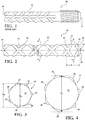
- FIG. 2 is a perspective view of a stud weldable rebar 20 in accordance with an aspect of the subject disclosure.
- the stud weldable rebar 20 includes a steel bar 22 of a generally cylindrical shape which extends along an axis A from a first end 24 to a second end 26.
- the steel bar 22 is comprised of a material composition which conforms to the requirements of ASTM 706.
- the steel bar 22 also conforms to the requirements for nominal weight, nominal diameter, perimeter, and deformation as also forth in ASTM 706.
- the steel bar 22 includes a plurality of deformations or ridges, such as inclined transverse ribs 28, which are disposed along the steel bar 22 between the first and second ends 24, 26.
- the steel bar 20 includes a base portion 30 which is disposed adjacent the first end 22.
- the base portion 30 has a base diameter D1, measured transversely to the axis A and inclusive of both a nominal diameter D n of the steel bar 22 as well as the plurality of ribs 28.
- the base diameter D1 defines a base cross-sectional area of the base portion 20 according to the equation ( ⁇ * D1 2 ) / 4.
- the steel bar 20 includes an upset portion 32 which is disposed adjacent the second end 22 and has an upset diameter D2, again measured transversely to the axis A, being greater than the base diameter D1.
- the upset diameter D2 defines an upset cross-sectional area of the upset portion 32 of the steel bar 22 according to the same equation, namely ( ⁇ * D2 2 ) / 4.
- the steel bar 22 includes a transition portion 34 which is sloped radially inward, preferably at a 30 degree angle, from the upset portion 32 to the base portion 30.
- the upset portion 32 has a length L extending axially from the transition portion 34 to the second end 26 of the steel bar 22.
- the second end 26 can have a flat surface extending transversely to the axis A, such as illustrated in Figure 2 , or alternatively could be hemispherical in shape.
- a flux load such as an aluminum ball 36, is pressed into second end 26 to act as flux for stud welding of the rebar 20.
- the upset portion 32 can also include a chamfer 38 disposed adjacent the second end 26 and which slopes radially inward towards the second end 26, such as a 30 or 45 degree angle, plus or minus 2 degrees.
- a chamfer 38 disposed adjacent the second end 26 and which slopes radially inward towards the second end 26, such as a 30 or 45 degree angle, plus or minus 2 degrees.
- other angles of the chamfer 38 can be utilized without departing from the scope of the subject disclosure.
- the stud weldable rebar 20 includes an upset portion 32 having an upset cross-sectional area that is approximately 13.5% to 22.5% greater than the base cross-sectional area. Additionally, the stud weldable rebar 20 includes an upset portion 32 that has an upset diameter D2 approximately 6.5% to 10.5 % greater than a base diameter D1 of the base portion 30.
- the steel bar 22 of the stud weldable rebar 20 conforms to the material composition requirements of ASTM A706.
- Applicant has surprisingly found that a steel bar 22 in accordance with more limiting composition ranges relative to the A706 composition requirements, in conjunction with the dimensional limitations provided immediately above in Table 1, provides for stud weldable A706 rebar that meets both the AWS D1.1 construction code industry standards as well as the seismic code ACI 318 requirements after stud welding.
- C eq % C + %Mn/6 + %Cu/40 + %Ni/20 + %Cr/10 - %Mo/50 - %V/10.
- a carbon equivalency of up to 0.55 percent is too high for stud welding.
- a steel bar 22 with a minimum carbon equivalent (C eq ) of 0.31 and a maximum carbon equivalent (C eq ) of 0.43 in conjunction with the dimensional limitations set forth in Table 1, provides for stud weldable A706 rebar.
- the following Table provides for the material compositions of the steel bar 22 which provides a more limiting A706 composition that meets this carbon equivalency (C eq ) range of 0.31 to 0.43.
- a method of manufacturing a stud weldable rebar includes obtaining a steel bar 22 having a base diameter D1 extending from a first end 24 to a second end 26 and a material composition which confirms to the requirements of ASTM 706 but with a restricted chemical composition, such as the preferred compositions provided in Table 2 above, to provide a carbon equivalency (C eq ) of the steel bar 22 between 0.31 and 0.43.
- the method proceeds by upsetting the second end 26 of the steel bar 22 to create an upset portion 32 disposed adjacent the second end 26 having an upset diameter D2 being greater than the base diameter D1 to define an upset cross-sectional area of the upset portion 32.
- the upset cross-sectional area is 13.5% to 22.5% greater than a base cross-sectional area of the base portion 30 to provide an A706 rebar 20 that meets both the AWS D1.1 construction code industry standards as well as the seismic code ACI 318 requirements after stud welding.
- the step of upsetting the second end 26 of the steel bar 22 also preferably includes upsetting the second end 26 of the steel bar 22 to establish the upset diameter D2 to approximately 6.5% to 10.5 % greater than the base diameter D1.
- the step of upsetting the second end 26 of the steel bar also preferably includes establishing a transition zone 34 extending between the base and upset portions 30, 32, with the transition portion 34 preferably sloped radially inward at a 30 degree angle from the upset portion 32 to the base portion 30.
- the step of upsetting the second end 26 of the steel bar 22 also includes establishing a length L of the upset portion 32 which extends axially from the transition portion 34 to the second end 26.
- the preferred dimensions of the base diameter D1, the upset diameter D2, the length L, as well as the relationship between the base cross-sectional area of the base portion 30 and the upset cross-sectional area of the upset portion 32 is set forth in Table 2 above.
Landscapes
- Engineering & Computer Science (AREA)
- Chemical & Material Sciences (AREA)
- Mechanical Engineering (AREA)
- Materials Engineering (AREA)
- Metallurgy (AREA)
- Organic Chemistry (AREA)
- Architecture (AREA)
- Civil Engineering (AREA)
- Structural Engineering (AREA)
- Reinforcement Elements For Buildings (AREA)
- Rod-Shaped Construction Members (AREA)
Description
- This section provides a general summary of background information and the comments and examples provided in this section are not necessarily prior art to the present disclosure.
- Concrete is a commonly-used construction material. Concrete is very strong in compression, but relatively weak in tension. Reinforcing steel, also known as "rebar," is a steel bar or mesh of steel wires used as a tension device in reinforced concrete and reinforced masonry structures to strengthen and hold the concrete in tension. Rebar is conventionally fabricated into round shapes for use in reinforced concrete and masonry.
- Rebar must meet industry standards, such as ASTM International A615/A615M-15 Standard for Deformed and Plain Carbon-Steel Bars for Concrete Reinforcement, and ASTM International A706/A706M-15 Standard Specification for Deformed and Plain Low-Alloy Steel Bars for Concrete Reinforcement (hereinafter "ASTM A706" ). Rebar used in construction as welded wire fabric or deformed bar anchor studs can alternatively meet ASTM A1064/A1064M-13 (hereinafter "ASTM A1064"). Rebar used in structures subject to certain potential seismic loading, a function of the anticipated intensity of ground shaking and other earthquake effects the structure is likely to experience and the structure's use, must meet the Structural Concrete Building Code, ACI 318-14 (hereinafter "ACI 318"), of the American Concrete Institute.
- Rebar can be arc welded. Arc welding, however, is a relatively time-consuming process. Furthermore, if a metal having high carbon content such as rebar is cooled too quickly after arc welding, it gets extremely brittle and hard. Accordingly, arc welding of rebar often involves preheating the material as well as specialized welding equipment and accessories in order to slow cooling and reduce brittleness.
US20020189175 discloses a friction welded rebar. - Another technique for fastening rebar to a base metal without the need for welding is to thread an end of the rebar. One such example is illustrated in
Figure 1 (not drawn to scale), in which athreadable rebar 10 includes asteel bar 12 which extends from afirst end 14 to a second threadedend 16. A threaded aperture (not expressly shown) is correspondingly created in the base metal and the threadedend 16 of therebar 10 is then threaded therein to fasten the threadedend 16 of therebar 10 to the base metal. However, this technique requires specialized equipment and extra steps to manufacture both the threadedend 16 of therebar 10 and the threaded aperture of the base metal as well as to assemble the threadedend 16 of therebar 10 into the threaded aperture of the base metal. - Stud welding is a technique for welding a fastener, such as a pin, stud or other fastener, to a base metal. The studs are welded to the base metal by establishing an electrical arc between the stud and the base metal to heat the metal at the tip of the stud and the base metal to a molten or liquid state and then plunging the stud into the base metal before the molten metal cools to solid state. Stud welding can be accomplished much more quickly than standard arc welding methods. However, stud welding must meet industry standards as well, such as American Welding Society Structural Welding Code Steel, AWS D1.1/D1.1M:2015 (23rd ed. July 28, 2015) (hereinafter "AWS D1.1' "). Additionally, studs must meet the ACI 318 standards if the stud is to be used in structures having certain potential seismic risk.
- Rebar can in some instances be stud welded. For example, rebar which meets the dimensional and strength requirements of ASTM A1064 can be stud welded. However, studs made from ASTM A1064 rebar material do not meet the seismic requirements of ACI 318. Accordingly, ASTM A1064 rebar cannot be stud welded in construction applications having a certain level of seismic loading.
- Thus, there remains a significant and continuing need for a stud weldable rebar that meet the AWS D1.1 industry standards for concrete construction as well as the ACI 318 standards for construction in seismic risk zones, without the need for pre-heat or specialized welding equipment, processes, or accessories.
- The present invention is directed to a high-strength low-alloy steel bar for concrete reinforcement according to independent claim 1 which meets the composition requirements of A706. The steel bar which meets the composition requirements of A706 extends along an axis A from a first end to a second end and includes a base portion disposed adjacent the first end which has a first diameter D1 to define a base cross-sectional area of the base portion of the steel bar. The steel bar also includes an upset portion disposed adjacent the second end which has a second diameter D2 being greater than the first diameter D1 to define an upset cross-sectional area of the upset portion of the steel bar being greater than the base cross-sectional area. The material composition of the steel bar is restricted to a carbon equivalency between 0.31 and 0.43 and the upset cross-sectional area is approximately 13.5-22.5% greater than the base cross-sectional area. Applicant has surprisingly found that A706 rebar which is restricted to this carbon equivalency and modified to establish this cross-sectional area relationship between the upset and base portions meet both the AWS D1.1 welding industry standards and the concrete code ACI 318 requirements after stud welding. In other words, A706 rebar which is restricted to a carbon equivalency between 0.31 and 0.43 and manufactured to include an upset cross-sectional area that is approximately 13.5-22.5% greater than the base cross-sectional area surprisingly provides a stud weldable rebar product which meets all of the industry standards without the need for pre-heat or specialized welding equipment and accessories.
- The drawings described herein are for illustrative purposes only of selected embodiments and not all possible implementations, and are not intended to limit the scope of the present disclosure.
-
FIG. 1 is a perspective side view of a prior art bar of threaded rebar; -
FIG. 2 is a perspective view of a steel bar according to the subject disclosure which extends from a first end to a second end along an axis A and includes a base portion disposed adjacent the first end and an upset portion disposed adjacent the second end; -
FIG. 3 is a cross-sectional view of the steel bar ofFigure 2 taken along 3-3 and illustrating a first diameter D1 of the base portion to define a base cross-sectional area of the steel bar; and -
FIG. 4 is a cross-sectional view of the bar ofFigure 2 taken along 4-4 and illustrating a second diameter D2 of the upset portion being greater than the first diameter D1 of the base portion to define an upset cross-sectional area of the steel bar being greater than the base cross-sectional area. - Example embodiments of a stud weldable rebar will now be more fully described. Each of these example embodiments are provided so that this disclosure is thorough and fully conveys the scope of the inventive concepts, features and advantages to those skilled in the art. To this end, numerous specific details are set forth such as examples of specific components, dimensions, and compositions to provide a thorough understanding of each of the embodiments associated with the present disclosure. However, as will be apparent to those skilled in the art, not all specific details described herein need to be employed, the example embodiments may be embodied in many different forms, and thus should not be construed or interpreted to limit the scope of the invention as defined by the appended claims.
-
Figure 2 is a perspective view of a studweldable rebar 20 in accordance with an aspect of the subject disclosure. As best shown therein, the studweldable rebar 20 includes a steel bar 22 of a generally cylindrical shape which extends along an axis A from afirst end 24 to asecond end 26. The steel bar 22 is comprised of a material composition which conforms to the requirements of ASTM 706. The steel bar 22 also conforms to the requirements for nominal weight, nominal diameter, perimeter, and deformation as also forth in ASTM 706. As is common in rebar, the steel bar 22 includes a plurality of deformations or ridges, such as inclinedtransverse ribs 28, which are disposed along the steel bar 22 between the first andsecond ends - As best illustrated in
Figure 2 , thesteel bar 20 includes abase portion 30 which is disposed adjacent the first end 22. As best illustrated inFigure 3 , thebase portion 30 has a base diameter D1, measured transversely to the axis A and inclusive of both a nominal diameter Dn of the steel bar 22 as well as the plurality ofribs 28. The base diameter D1 defines a base cross-sectional area of thebase portion 20 according to the equation (π * D12) / 4. As further illustrated inFigures 2 and 4 , thesteel bar 20 includes anupset portion 32 which is disposed adjacent the second end 22 and has an upset diameter D2, again measured transversely to the axis A, being greater than the base diameter D1. The upset diameter D2 defines an upset cross-sectional area of theupset portion 32 of the steel bar 22 according to the same equation, namely (π * D2 2) / 4. - As best shown in
Figure 2 , the steel bar 22 includes atransition portion 34 which is sloped radially inward, preferably at a 30 degree angle, from theupset portion 32 to thebase portion 30. Theupset portion 32 has a length L extending axially from thetransition portion 34 to thesecond end 26 of the steel bar 22. Thesecond end 26 can have a flat surface extending transversely to the axis A, such as illustrated inFigure 2 , or alternatively could be hemispherical in shape. A flux load, such as analuminum ball 36, is pressed intosecond end 26 to act as flux for stud welding of therebar 20. Theupset portion 32 can also include achamfer 38 disposed adjacent thesecond end 26 and which slopes radially inward towards thesecond end 26, such as a 30 or 45 degree angle, plus or minus 2 degrees. However, other angles of thechamfer 38 can be utilized without departing from the scope of the subject disclosure. - As set forth in the following table, the stud
weldable rebar 20 includes anupset portion 32 having an upset cross-sectional area that is approximately 13.5% to 22.5% greater than the base cross-sectional area. Additionally, the studweldable rebar 20 includes anupset portion 32 that has an upset diameter D2 approximately 6.5% to 10.5 % greater than a base diameter D1 of thebase portion 30.TABLE 1: Preferred Dimensions of the Stud Weldable Rebar Nominal Bar Size D1 (+/- 0.005) Cross-sectional area of D1 base portion (cm2) D2 L (+/- 0.025) Cross-sectional area of D2 upset portion (cm2) Area increase base to upset Increase D1 to D2 3/8 1.0262 cm (0.404") 0.8270 (0.1282 in2) 1.0948-1.1201 cm (0.431-0.441") 1.1582cm (0.456") 0.9413-0.985159 (0.1459 - 0.1527 in2) 13.81 - 19.16 % 6.7 - 9.2 % 1/2 1.369 cm (0.539") 1.4722 (0.2282 in2) 1.4605-1.4986 cm (0.575-0.590") 1.5443cm (0.608") 1.6755 -.1.7629 (0.2597 - 0.2734 in2) 13.80 - 19.82% 6.7 - 9.5 % 5/8 1.6789 cm (0.661") 2.2142 (0.3432 in2) 1.7958-1.8466 cm (0.707-0.727") 1.8974cm (0.747") 2.5329 -.2.6781 (0.3926 - 0.4151 in2) 14.40 - 20.97% 7.0 - 10.0 % 3/4 2.0955 cm (0.825") 3.4490 (0.5346 in2) 2.2352-2.2987 cm (0.880-0.905") 2.3622cm (0.930") 3.9239 - 4.1503 (0.6082 - 0.6433 in2) 13.78 - 20.33% 6.7 - 9.7 % 7/8 2.4409 cm (0.961") 4.6793 (0.7253 in2) 2.6035-2.6924 cm (1.025-1.060") 2.7508cm (1.083") 5.3239 - 5.6935 (0.8252 - 0.8825 in2) 13.76 - 21.66% 6.7 - 10.3 % 1 2.7889 cm (1.098") 6.1090 (0.9469 in2) 2.9718-3.0861 cm (1.170-1.215") 3.14198cm (1.237) 6.9361 - 7.4800 (1.0751 - 1.1594 in2) 13.54 - 22.45% 6.6 - 10.6 % - As previously mentioned, the steel bar 22 of the stud
weldable rebar 20 conforms to the material composition requirements of ASTM A706. However, Applicant has surprisingly found that a steel bar 22 in accordance with more limiting composition ranges relative to the A706 composition requirements, in conjunction with the dimensional limitations provided immediately above in Table 1, provides for stud weldable A706 rebar that meets both the AWS D1.1 construction code industry standards as well as the seismic code ACI 318 requirements after stud welding. More specifically, steel bars that meet the chemical composition requirements of ASTM A706 can have a carbon equivalency (Ceq) of up to 0.55 percent, with the carbon equivalency calculated according to the following equation: Ceq = % C + %Mn/6 + %Cu/40 + %Ni/20 + %Cr/10 - %Mo/50 - %V/10. However, a carbon equivalency of up to 0.55 percent is too high for stud welding. Applicant has surprisingly found that a steel bar 22 with a minimum carbon equivalent (Ceq) of 0.31 and a maximum carbon equivalent (Ceq) of 0.43, in conjunction with the dimensional limitations set forth in Table 1, provides for stud weldable A706 rebar. The following Table provides for the material compositions of the steel bar 22 which provides a more limiting A706 composition that meets this carbon equivalency (Ceq) range of 0.31 to 0.43.TABLE 2: Preferred Material Compositions of the Stud Weldable Rebar Element Range in percent by weight More preferable range in percent by weight Most preferable range in percent by weight Carbon (C) 0.080 - 0.330 0.080 - 0.230 0.080 -0.210 Manganese (Mn) 0.001 - 1.56 0.30- 1.20 1.00- 1.20 Phosphorus (P) 0.043 max 0.040 max 0.030 max Sulfur (S) 0.053 max 0.050 max 0.030 max Silicon (Si) 0.001 - 0.550 0.200 - 0.40 0.200 - 0.30 Copper (Cu) 0.250 max 0.250 max 0.250 max Nickel (Ni) 0.150 max 0.150 max 0.150 max Chromium (Cr) 0.150 max 0.150 max 0.150 max Molybdenum (Mo) 0.001 - 0.050 0.001 - 0.050 0.001 - 0.040 Aluminum (Al)A 0.001 - 0.060 0.001 - 0.020 0.001 - 0.015 Vanadium (V) 0.001 - 0.080 0.030 - 0.080 0.060 - 0.080 Boron (B) 0.0005 max 0.0005 max 0.0005 max Nitrogen (N) 0.020 max 0.020 max 0.020 max A Aluminum minimum sufficient to bind nitrogen. - A method of manufacturing a stud weldable rebar includes obtaining a steel bar 22 having a base diameter D1 extending from a
first end 24 to asecond end 26 and a material composition which confirms to the requirements of ASTM 706 but with a restricted chemical composition, such as the preferred compositions provided in Table 2 above, to provide a carbon equivalency (Ceq) of the steel bar 22 between 0.31 and 0.43. The method proceeds by upsetting thesecond end 26 of the steel bar 22 to create anupset portion 32 disposed adjacent thesecond end 26 having an upset diameter D2 being greater than the base diameter D1 to define an upset cross-sectional area of theupset portion 32. The upset cross-sectional area is 13.5% to 22.5% greater than a base cross-sectional area of thebase portion 30 to provide anA706 rebar 20 that meets both the AWS D1.1 construction code industry standards as well as the seismic code ACI 318 requirements after stud welding. The step of upsetting thesecond end 26 of the steel bar 22 also preferably includes upsetting thesecond end 26 of the steel bar 22 to establish the upset diameter D2 to approximately 6.5% to 10.5 % greater than the base diameter D1. The step of upsetting thesecond end 26 of the steel bar also preferably includes establishing atransition zone 34 extending between the base andupset portions transition portion 34 preferably sloped radially inward at a 30 degree angle from theupset portion 32 to thebase portion 30. The step of upsetting thesecond end 26 of the steel bar 22 also includes establishing a length L of theupset portion 32 which extends axially from thetransition portion 34 to thesecond end 26. The preferred dimensions of the base diameter D1, the upset diameter D2, the length L, as well as the relationship between the base cross-sectional area of thebase portion 30 and the upset cross-sectional area of theupset portion 32 is set forth in Table 2 above. Once therebar 20 is manufactured, thesecond end 26 of the steel bar 22 can be stud welded to a base metal to meet the aforementioned industry standards. - The foregoing description of the embodiments has been provided for purposes of illustration and description. It is not intended to be exhaustive or to limit the disclosure. Individual elements or features of a particular embodiment are generally not limited to that particular embodiment, but, where applicable, are interchangeable and can be used in a selected embodiment, even if not specifically shown or described. The same may also be varied in many ways. Such variations are not to be regarded as a departure from the disclosure, and all such modifications are intended to be included within the scope of the invention as defined in the appended claims.
Claims (15)
- A stud weldable rebar (20) comprising:a steel bar (22) extending along an axis (A) from a first end (24) to a second end (26) and comprised of a material composition having:0.080 - 0.330 wt. % of carbon;0.001 - 1.56 wt. % of manganese;less than 0.043 wt. % of phosphorus;less than 0.053 wt. % of sulphur;0.001 - 0.550 wt. % of silicon;0.001 - 0.050 wt. % of molybdenum;0.001 - 0.060 wt. % of aluminum; and0.001 - 0.080 wt. % of vanadium;said steel bar (22) including a base portion (30) disposed adjacent said first end having a base diameter (D1) to define a base cross-sectional area of said base portion of said steel bar;said steel bar including an upset portion (32) disposed adjacent said second end;said upset portion (32) having an upset diameter (D2) being greater than said base diameter (D1) to define an upset cross-sectional area of said upset portion of said steel bar being greater than said base cross-sectional area;said material composition of said steel bar having a carbon equivalency between 0.31 and 0.43; andsaid upset cross-sectional area being approximately 13.5% to 22.5% greater than said base cross-sectional area.
- A stud weldable rebar (20) as set forth in claim 1 wherein said upset diameter (D2) is approximately 6.5% to 10.5 % greater than said base diameter (D1).
- A stud weldable rebar (20) as set forth in either claim 1 or claim 2, wherein said steel bar includes a transition portion which slopes radially inward from said upset portion to said base portion, and said upset portion has a length (L) extending axially from said transition portion to said second end.
- A stud weldable rebar (20) as set forth in claim 3, wherein said base diameter (D1) is approximately 1.0135 cm to 1.0389 cm (0.399 to 0.409 inches) and said upset diameter (D2) is approximately 1.0948 cm to 1.1201 cm (0.431 to 0.441 inches).
- A stud weldable rebar (20) as set forth in claim 4, wherein said length (L) of said upset portion is approximately 1.0948 cm to 1.2218 cm (0.431 to 0.481 inches).
- A stud weldable rebar (20) as set forth in claim 3, wherein said base diameter (D1) is approximately 1.3534 cm to 1.3818 cm (0.534 to 0.544 inches) and said upset diameter (D2) is approximately 1.4605 cm to 1.4986 cm (0.575 to 5.590 inches).
- A stud weldable rebar (20) as set forth in claim 6, wherein said length of said upset portion is approximately 1.4808 cm to 1.6078 cm (0.583 to 0.633 inches).
- A stud weldable rebar (20) as set forth in claim 3, wherein said base diameter (D1) is approximately 1.6662 cm to 1.6916 cm (0.656 to 0.666 inches) and said upset diameter (D2) is approximately 1.7958 cm to 1.8466 cm (0.707 to 0.727 inches).
- A stud weldable rebar (20) as set forth in claim 8, wherein said length (L) of said upset portion is approximately 1.8415 cm to 1.9609 cm (0.725 to 0.772 inches).
- A stud weldable rebar (20) as set forth in claim 3, wherein said base diameter (D1) is approximately 2.0828 cm to 2.1082 cm (0.820 to 0.830 inches) and said upset diameter (D2) is approximately 2.2352 cm to 2.2987 cm (0.880 to 0.905 inches).
- A stud weldable rebar (20) as set forth in claim 10, wherein said length (L) of said upset portion is approximately 2.2987 cm to 2.4257 cm (0.905 to 0.955 inches).
- A stud weldable rebar (20) as set forth in claim 3, wherein said base diameter (D1) is approximately 2.4282 cm 2.4536 cm (0.956 to 0.966 inches) and said upset diameter (D2) is approximately 2.6035 cm to 2.6924 cm (1.025 to 1.060 inches).
- A stud weldable rebar (20) as set forth in claim 12, wherein said length (L) of said upset portion is approximately 2.6873 cm to 2.8143 cm (1.058 to 1.108 inches).
- A stud weldable rebar (20) as set forth in claim 3, wherein said base diameter (D1) is approximately 2.7762 cm to 2.8016 cm (1.093 to 1.103 inches) and said upset diameter (D2) is approximately 2.9718 cm to 3.0861 cm (1.170 to 1.215 inches).
- A stud weldable rebar (20) as set forth in claim 14, wherein said length (L) of said upset portion is approximately 3.0785 cm to 3.2055 cm.
Applications Claiming Priority (2)
| Application Number | Priority Date | Filing Date | Title |
|---|---|---|---|
| US201662300986P | 2016-02-29 | 2016-02-29 | |
| PCT/US2017/019905 WO2017151590A1 (en) | 2016-02-29 | 2017-02-28 | Stud weldable rebar |
Publications (2)
| Publication Number | Publication Date |
|---|---|
| EP3423647A1 EP3423647A1 (en) | 2019-01-09 |
| EP3423647B1 true EP3423647B1 (en) | 2021-03-31 |
Family
ID=59678987
Family Applications (1)
| Application Number | Title | Priority Date | Filing Date |
|---|---|---|---|
| EP17712876.6A Active EP3423647B1 (en) | 2016-02-29 | 2017-02-28 | Stud weldable rebar |
Country Status (7)
| Country | Link |
|---|---|
| US (1) | US10145113B2 (en) |
| EP (1) | EP3423647B1 (en) |
| JP (1) | JP6968079B2 (en) |
| CN (1) | CN108713086B (en) |
| BR (1) | BR112018017273B1 (en) |
| CA (1) | CA3015361C (en) |
| WO (1) | WO2017151590A1 (en) |
Families Citing this family (4)
| Publication number | Priority date | Publication date | Assignee | Title |
|---|---|---|---|---|
| US10145113B2 (en) * | 2016-02-29 | 2018-12-04 | Nelson Stud Welding, Inc. | Stud weldable rebar |
| DE202017104918U1 (en) * | 2017-08-16 | 2017-10-23 | Pfeifer Holding Gmbh & Co. Kg | Tension rod or push rod with corrosion resistant thread flanks |
| US11180821B2 (en) | 2019-03-07 | 2021-11-23 | TFP Corporation | Stud-weldable rebar |
| US12000104B1 (en) * | 2022-03-10 | 2024-06-04 | Theo Robert Seeley | Green gravity retaining wall |
Citations (1)
| Publication number | Priority date | Publication date | Assignee | Title |
|---|---|---|---|---|
| CN101481780B (en) * | 2008-12-06 | 2012-03-14 | 燕山大学 | Easy-to-weld superfine austenite crystal steel with superhigh intensity and high tenacity and manufacturing method thereof |
Family Cites Families (12)
| Publication number | Priority date | Publication date | Assignee | Title |
|---|---|---|---|---|
| US5152118A (en) * | 1990-08-13 | 1992-10-06 | Richmond Screw Anchor Co., Inc. | Couplings for concrete reinforcement bars |
| US5776001A (en) * | 1994-02-16 | 1998-07-07 | Ccl Systems Limited | Thread formation |
| US6023990A (en) * | 1997-01-17 | 2000-02-15 | Carr; John | Bimetallic gear rim |
| US20020189175A1 (en) * | 2001-06-15 | 2002-12-19 | Lancelot Harry B. | End anchors |
| JP2004124140A (en) * | 2002-10-01 | 2004-04-22 | Jfe Steel Kk | Deformed steel bar for rebar excellent in resistance weldability and method for producing the same |
| JP2010255201A (en) * | 2009-04-21 | 2010-11-11 | Dai Ichi High Frequency Co Ltd | Reinforcing bar with expanded diameter part, joint member for reinforcing bar, and method for connecting reinforcing bar |
| KR20120065757A (en) * | 2010-12-13 | 2012-06-21 | 롯데건설 주식회사 | Construction method using high strength shear stud |
| JP6045823B2 (en) * | 2012-06-28 | 2016-12-14 | 共英製鋼株式会社 | Manufacturing method of reinforcing steel bars used for stud welding |
| US20140237935A1 (en) * | 2013-02-26 | 2014-08-28 | Nucor Corporation | Ultra-high strength rebar |
| US9266165B2 (en) * | 2013-05-04 | 2016-02-23 | Christian L. Dahl | Method for hot forging threads into an end of a steel bar |
| JP6358882B2 (en) * | 2014-07-25 | 2018-07-18 | ダイヘンスタッド株式会社 | Welding equipment and rust-proof coated steel bars |
| US10145113B2 (en) * | 2016-02-29 | 2018-12-04 | Nelson Stud Welding, Inc. | Stud weldable rebar |
-
2017
- 2017-02-28 US US15/445,011 patent/US10145113B2/en active Active
- 2017-02-28 WO PCT/US2017/019905 patent/WO2017151590A1/en not_active Ceased
- 2017-02-28 JP JP2018545383A patent/JP6968079B2/en active Active
- 2017-02-28 BR BR112018017273-1A patent/BR112018017273B1/en active IP Right Grant
- 2017-02-28 CA CA3015361A patent/CA3015361C/en active Active
- 2017-02-28 EP EP17712876.6A patent/EP3423647B1/en active Active
- 2017-02-28 CN CN201780014093.5A patent/CN108713086B/en active Active
Patent Citations (1)
| Publication number | Priority date | Publication date | Assignee | Title |
|---|---|---|---|---|
| CN101481780B (en) * | 2008-12-06 | 2012-03-14 | 燕山大学 | Easy-to-weld superfine austenite crystal steel with superhigh intensity and high tenacity and manufacturing method thereof |
Also Published As
| Publication number | Publication date |
|---|---|
| CA3015361C (en) | 2023-10-31 |
| JP6968079B2 (en) | 2021-11-17 |
| BR112018017273A8 (en) | 2022-09-13 |
| US10145113B2 (en) | 2018-12-04 |
| BR112018017273A2 (en) | 2019-01-15 |
| US20170247884A1 (en) | 2017-08-31 |
| CN108713086B (en) | 2021-06-25 |
| JP2019516008A (en) | 2019-06-13 |
| EP3423647A1 (en) | 2019-01-09 |
| CN108713086A (en) | 2018-10-26 |
| BR112018017273B1 (en) | 2023-10-10 |
| WO2017151590A1 (en) | 2017-09-08 |
| CA3015361A1 (en) | 2017-09-08 |
Similar Documents
| Publication | Publication Date | Title |
|---|---|---|
| US10145113B2 (en) | Stud weldable rebar | |
| DE10014078C2 (en) | Method for producing a welding stud | |
| US9212486B2 (en) | Column structure and base member | |
| US11566300B2 (en) | Stud-weldable rebar | |
| US20200200297A1 (en) | Concrete Reinforcement Elements and Structures | |
| EP2796573A1 (en) | Drill rod and method in order to manufacture the same | |
| WO2017176741A1 (en) | Lockbolt fastening system | |
| DE4011486A1 (en) | CONCRETE RIBBON STEEL WITH COLD-ROLLED CRANKS AND USE THEREOF | |
| US1821850A (en) | Tapered tubular pole | |
| EP3202924A1 (en) | Protective fences | |
| US20170338573A1 (en) | Swage high voltage cable terminal | |
| KR100907398B1 (en) | Manufacturing method of reinforcing bar with fixing part | |
| WO2016118064A1 (en) | Dynamic rock bolt and method of manufacturing a tension bar in a dynamic rock bolt | |
| AU774543B2 (en) | Cold formed flat-rolled steel structural members | |
| KR200325665Y1 (en) | Lattice girder having high strength steel wire | |
| JPS623848A (en) | Studded and flash-welded anchor chain having excellent resistance to fatigue | |
| EP2796216A1 (en) | Band-shaped metal sheet | |
| JPH09279304A (en) | High-strength steel wire having welded portion and method of manufacturing the same | |
| EP1498366A1 (en) | Method for a link to a rod and conveyor belt with such link/rod connections | |
| CA2488149A1 (en) | Polymer concrete pipe | |
| JP3403796B2 (en) | Braiding method of PC structure reinforcement | |
| CN210601005U (en) | Hot rolled steel wire rod | |
| UPADHYAY et al. | An Experimental Study on the Ratio of Tensile Strength to Yield strength of two different grades of Reinforcing Bars | |
| EP3500389B1 (en) | Method of welding a cold-rolled narrow strip in the form of flat wire or profiled element made of a twip steel for use in flexible pipes and a welded cold-rolled narrow strip | |
| JPWO2001023118A1 (en) | Method for processing connecting ends of deformed steel bars for concrete reinforcement and deformed steel bars processed by this method |
Legal Events
| Date | Code | Title | Description |
|---|---|---|---|
| STAA | Information on the status of an ep patent application or granted ep patent |
Free format text: STATUS: UNKNOWN |
|
| STAA | Information on the status of an ep patent application or granted ep patent |
Free format text: STATUS: THE INTERNATIONAL PUBLICATION HAS BEEN MADE |
|
| PUAI | Public reference made under article 153(3) epc to a published international application that has entered the european phase |
Free format text: ORIGINAL CODE: 0009012 |
|
| STAA | Information on the status of an ep patent application or granted ep patent |
Free format text: STATUS: REQUEST FOR EXAMINATION WAS MADE |
|
| 17P | Request for examination filed |
Effective date: 20181024 |
|
| AK | Designated contracting states |
Kind code of ref document: A1 Designated state(s): AL AT BE BG CH CY CZ DE DK EE ES FI FR GB GR HR HU IE IS IT LI LT LU LV MC MK MT NL NO PL PT RO RS SE SI SK SM TR |
|
| AX | Request for extension of the european patent |
Extension state: BA ME |
|
| DAV | Request for validation of the european patent (deleted) | ||
| DAX | Request for extension of the european patent (deleted) | ||
| STAA | Information on the status of an ep patent application or granted ep patent |
Free format text: STATUS: EXAMINATION IS IN PROGRESS |
|
| 17Q | First examination report despatched |
Effective date: 20190701 |
|
| GRAP | Despatch of communication of intention to grant a patent |
Free format text: ORIGINAL CODE: EPIDOSNIGR1 |
|
| STAA | Information on the status of an ep patent application or granted ep patent |
Free format text: STATUS: GRANT OF PATENT IS INTENDED |
|
| INTG | Intention to grant announced |
Effective date: 20201127 |
|
| GRAS | Grant fee paid |
Free format text: ORIGINAL CODE: EPIDOSNIGR3 |
|
| GRAA | (expected) grant |
Free format text: ORIGINAL CODE: 0009210 |
|
| STAA | Information on the status of an ep patent application or granted ep patent |
Free format text: STATUS: THE PATENT HAS BEEN GRANTED |
|
| AK | Designated contracting states |
Kind code of ref document: B1 Designated state(s): AL AT BE BG CH CY CZ DE DK EE ES FI FR GB GR HR HU IE IS IT LI LT LU LV MC MK MT NL NO PL PT RO RS SE SI SK SM TR |
|
| REG | Reference to a national code |
Ref country code: GB Ref legal event code: FG4D Ref country code: CH Ref legal event code: EP |
|
| REG | Reference to a national code |
Ref country code: DE Ref legal event code: R096 Ref document number: 602017035635 Country of ref document: DE Ref country code: AT Ref legal event code: REF Ref document number: 1377074 Country of ref document: AT Kind code of ref document: T Effective date: 20210415 |
|
| REG | Reference to a national code |
Ref country code: IE Ref legal event code: FG4D |
|
| REG | Reference to a national code |
Ref country code: LT Ref legal event code: MG9D |
|
| PG25 | Lapsed in a contracting state [announced via postgrant information from national office to epo] |
Ref country code: BG Free format text: LAPSE BECAUSE OF FAILURE TO SUBMIT A TRANSLATION OF THE DESCRIPTION OR TO PAY THE FEE WITHIN THE PRESCRIBED TIME-LIMIT Effective date: 20210630 Ref country code: NO Free format text: LAPSE BECAUSE OF FAILURE TO SUBMIT A TRANSLATION OF THE DESCRIPTION OR TO PAY THE FEE WITHIN THE PRESCRIBED TIME-LIMIT Effective date: 20210630 Ref country code: FI Free format text: LAPSE BECAUSE OF FAILURE TO SUBMIT A TRANSLATION OF THE DESCRIPTION OR TO PAY THE FEE WITHIN THE PRESCRIBED TIME-LIMIT Effective date: 20210331 Ref country code: HR Free format text: LAPSE BECAUSE OF FAILURE TO SUBMIT A TRANSLATION OF THE DESCRIPTION OR TO PAY THE FEE WITHIN THE PRESCRIBED TIME-LIMIT Effective date: 20210331 |
|
| PG25 | Lapsed in a contracting state [announced via postgrant information from national office to epo] |
Ref country code: LV Free format text: LAPSE BECAUSE OF FAILURE TO SUBMIT A TRANSLATION OF THE DESCRIPTION OR TO PAY THE FEE WITHIN THE PRESCRIBED TIME-LIMIT Effective date: 20210331 Ref country code: RS Free format text: LAPSE BECAUSE OF FAILURE TO SUBMIT A TRANSLATION OF THE DESCRIPTION OR TO PAY THE FEE WITHIN THE PRESCRIBED TIME-LIMIT Effective date: 20210331 Ref country code: SE Free format text: LAPSE BECAUSE OF FAILURE TO SUBMIT A TRANSLATION OF THE DESCRIPTION OR TO PAY THE FEE WITHIN THE PRESCRIBED TIME-LIMIT Effective date: 20210331 |
|
| REG | Reference to a national code |
Ref country code: NL Ref legal event code: MP Effective date: 20210331 |
|
| REG | Reference to a national code |
Ref country code: AT Ref legal event code: MK05 Ref document number: 1377074 Country of ref document: AT Kind code of ref document: T Effective date: 20210331 |
|
| PG25 | Lapsed in a contracting state [announced via postgrant information from national office to epo] |
Ref country code: SM Free format text: LAPSE BECAUSE OF FAILURE TO SUBMIT A TRANSLATION OF THE DESCRIPTION OR TO PAY THE FEE WITHIN THE PRESCRIBED TIME-LIMIT Effective date: 20210331 Ref country code: NL Free format text: LAPSE BECAUSE OF FAILURE TO SUBMIT A TRANSLATION OF THE DESCRIPTION OR TO PAY THE FEE WITHIN THE PRESCRIBED TIME-LIMIT Effective date: 20210331 Ref country code: AT Free format text: LAPSE BECAUSE OF FAILURE TO SUBMIT A TRANSLATION OF THE DESCRIPTION OR TO PAY THE FEE WITHIN THE PRESCRIBED TIME-LIMIT Effective date: 20210331 Ref country code: CZ Free format text: LAPSE BECAUSE OF FAILURE TO SUBMIT A TRANSLATION OF THE DESCRIPTION OR TO PAY THE FEE WITHIN THE PRESCRIBED TIME-LIMIT Effective date: 20210331 Ref country code: EE Free format text: LAPSE BECAUSE OF FAILURE TO SUBMIT A TRANSLATION OF THE DESCRIPTION OR TO PAY THE FEE WITHIN THE PRESCRIBED TIME-LIMIT Effective date: 20210331 Ref country code: LT Free format text: LAPSE BECAUSE OF FAILURE TO SUBMIT A TRANSLATION OF THE DESCRIPTION OR TO PAY THE FEE WITHIN THE PRESCRIBED TIME-LIMIT Effective date: 20210331 |
|
| PG25 | Lapsed in a contracting state [announced via postgrant information from national office to epo] |
Ref country code: IS Free format text: LAPSE BECAUSE OF FAILURE TO SUBMIT A TRANSLATION OF THE DESCRIPTION OR TO PAY THE FEE WITHIN THE PRESCRIBED TIME-LIMIT Effective date: 20210731 Ref country code: PT Free format text: LAPSE BECAUSE OF FAILURE TO SUBMIT A TRANSLATION OF THE DESCRIPTION OR TO PAY THE FEE WITHIN THE PRESCRIBED TIME-LIMIT Effective date: 20210802 Ref country code: PL Free format text: LAPSE BECAUSE OF FAILURE TO SUBMIT A TRANSLATION OF THE DESCRIPTION OR TO PAY THE FEE WITHIN THE PRESCRIBED TIME-LIMIT Effective date: 20210331 Ref country code: SK Free format text: LAPSE BECAUSE OF FAILURE TO SUBMIT A TRANSLATION OF THE DESCRIPTION OR TO PAY THE FEE WITHIN THE PRESCRIBED TIME-LIMIT Effective date: 20210331 Ref country code: RO Free format text: LAPSE BECAUSE OF FAILURE TO SUBMIT A TRANSLATION OF THE DESCRIPTION OR TO PAY THE FEE WITHIN THE PRESCRIBED TIME-LIMIT Effective date: 20210331 |
|
| REG | Reference to a national code |
Ref country code: DE Ref legal event code: R097 Ref document number: 602017035635 Country of ref document: DE |
|
| PG25 | Lapsed in a contracting state [announced via postgrant information from national office to epo] |
Ref country code: ES Free format text: LAPSE BECAUSE OF FAILURE TO SUBMIT A TRANSLATION OF THE DESCRIPTION OR TO PAY THE FEE WITHIN THE PRESCRIBED TIME-LIMIT Effective date: 20210331 Ref country code: DK Free format text: LAPSE BECAUSE OF FAILURE TO SUBMIT A TRANSLATION OF THE DESCRIPTION OR TO PAY THE FEE WITHIN THE PRESCRIBED TIME-LIMIT Effective date: 20210331 Ref country code: AL Free format text: LAPSE BECAUSE OF FAILURE TO SUBMIT A TRANSLATION OF THE DESCRIPTION OR TO PAY THE FEE WITHIN THE PRESCRIBED TIME-LIMIT Effective date: 20210331 |
|
| PLBE | No opposition filed within time limit |
Free format text: ORIGINAL CODE: 0009261 |
|
| STAA | Information on the status of an ep patent application or granted ep patent |
Free format text: STATUS: NO OPPOSITION FILED WITHIN TIME LIMIT |
|
| 26N | No opposition filed |
Effective date: 20220104 |
|
| PG25 | Lapsed in a contracting state [announced via postgrant information from national office to epo] |
Ref country code: IS Free format text: LAPSE BECAUSE OF FAILURE TO SUBMIT A TRANSLATION OF THE DESCRIPTION OR TO PAY THE FEE WITHIN THE PRESCRIBED TIME-LIMIT Effective date: 20210731 |
|
| PG25 | Lapsed in a contracting state [announced via postgrant information from national office to epo] |
Ref country code: IT Free format text: LAPSE BECAUSE OF FAILURE TO SUBMIT A TRANSLATION OF THE DESCRIPTION OR TO PAY THE FEE WITHIN THE PRESCRIBED TIME-LIMIT Effective date: 20210331 |
|
| PG25 | Lapsed in a contracting state [announced via postgrant information from national office to epo] |
Ref country code: MC Free format text: LAPSE BECAUSE OF FAILURE TO SUBMIT A TRANSLATION OF THE DESCRIPTION OR TO PAY THE FEE WITHIN THE PRESCRIBED TIME-LIMIT Effective date: 20210331 |
|
| REG | Reference to a national code |
Ref country code: CH Ref legal event code: PL |
|
| REG | Reference to a national code |
Ref country code: BE Ref legal event code: MM Effective date: 20220228 |
|
| PG25 | Lapsed in a contracting state [announced via postgrant information from national office to epo] |
Ref country code: LU Free format text: LAPSE BECAUSE OF NON-PAYMENT OF DUE FEES Effective date: 20220228 |
|
| PG25 | Lapsed in a contracting state [announced via postgrant information from national office to epo] |
Ref country code: FR Free format text: LAPSE BECAUSE OF NON-PAYMENT OF DUE FEES Effective date: 20220228 |
|
| PG25 | Lapsed in a contracting state [announced via postgrant information from national office to epo] |
Ref country code: LI Free format text: LAPSE BECAUSE OF NON-PAYMENT OF DUE FEES Effective date: 20220228 Ref country code: IE Free format text: LAPSE BECAUSE OF NON-PAYMENT OF DUE FEES Effective date: 20220228 Ref country code: CH Free format text: LAPSE BECAUSE OF NON-PAYMENT OF DUE FEES Effective date: 20220228 |
|
| PG25 | Lapsed in a contracting state [announced via postgrant information from national office to epo] |
Ref country code: BE Free format text: LAPSE BECAUSE OF NON-PAYMENT OF DUE FEES Effective date: 20220228 |
|
| PG25 | Lapsed in a contracting state [announced via postgrant information from national office to epo] |
Ref country code: HU Free format text: LAPSE BECAUSE OF FAILURE TO SUBMIT A TRANSLATION OF THE DESCRIPTION OR TO PAY THE FEE WITHIN THE PRESCRIBED TIME-LIMIT; INVALID AB INITIO Effective date: 20170228 |
|
| PG25 | Lapsed in a contracting state [announced via postgrant information from national office to epo] |
Ref country code: MK Free format text: LAPSE BECAUSE OF FAILURE TO SUBMIT A TRANSLATION OF THE DESCRIPTION OR TO PAY THE FEE WITHIN THE PRESCRIBED TIME-LIMIT Effective date: 20210331 Ref country code: CY Free format text: LAPSE BECAUSE OF FAILURE TO SUBMIT A TRANSLATION OF THE DESCRIPTION OR TO PAY THE FEE WITHIN THE PRESCRIBED TIME-LIMIT Effective date: 20210331 |
|
| PG25 | Lapsed in a contracting state [announced via postgrant information from national office to epo] |
Ref country code: MT Free format text: LAPSE BECAUSE OF FAILURE TO SUBMIT A TRANSLATION OF THE DESCRIPTION OR TO PAY THE FEE WITHIN THE PRESCRIBED TIME-LIMIT Effective date: 20210331 |
|
| PG25 | Lapsed in a contracting state [announced via postgrant information from national office to epo] |
Ref country code: GR Free format text: LAPSE BECAUSE OF NON-PAYMENT OF DUE FEES Effective date: 20210331 |
|
| PG25 | Lapsed in a contracting state [announced via postgrant information from national office to epo] |
Ref country code: GR Free format text: LAPSE BECAUSE OF NON-PAYMENT OF DUE FEES Effective date: 20210331 |
|
| PG25 | Lapsed in a contracting state [announced via postgrant information from national office to epo] |
Ref country code: TR Free format text: LAPSE BECAUSE OF FAILURE TO SUBMIT A TRANSLATION OF THE DESCRIPTION OR TO PAY THE FEE WITHIN THE PRESCRIBED TIME-LIMIT Effective date: 20210331 |
|
| PGFP | Annual fee paid to national office [announced via postgrant information from national office to epo] |
Ref country code: GB Payment date: 20260219 Year of fee payment: 10 |
|
| PGFP | Annual fee paid to national office [announced via postgrant information from national office to epo] |
Ref country code: DE Payment date: 20260217 Year of fee payment: 10 |