EP3423407B1 - Electrically enhanced haber-bosch (eehb) anhydrous ammonia synthesis - Google Patents
Electrically enhanced haber-bosch (eehb) anhydrous ammonia synthesis Download PDFInfo
- Publication number
- EP3423407B1 EP3423407B1 EP17760719.9A EP17760719A EP3423407B1 EP 3423407 B1 EP3423407 B1 EP 3423407B1 EP 17760719 A EP17760719 A EP 17760719A EP 3423407 B1 EP3423407 B1 EP 3423407B1
- Authority
- EP
- European Patent Office
- Prior art keywords
- catalyst
- reactor
- electride
- support
- gas
- Prior art date
- Legal status (The legal status is an assumption and is not a legal conclusion. Google has not performed a legal analysis and makes no representation as to the accuracy of the status listed.)
- Active
Links
Images







Classifications
-
- C—CHEMISTRY; METALLURGY
- C01—INORGANIC CHEMISTRY
- C01C—AMMONIA; CYANOGEN; COMPOUNDS THEREOF
- C01C1/00—Ammonia; Compounds thereof
- C01C1/02—Preparation, purification or separation of ammonia
- C01C1/04—Preparation of ammonia by synthesis
- C01C1/0405—Preparation of ammonia by synthesis from N2 and H2 in presence of a catalyst
- C01C1/0411—Preparation of ammonia by synthesis from N2 and H2 in presence of a catalyst characterised by the catalyst
-
- B—PERFORMING OPERATIONS; TRANSPORTING
- B01—PHYSICAL OR CHEMICAL PROCESSES OR APPARATUS IN GENERAL
- B01J—CHEMICAL OR PHYSICAL PROCESSES, e.g. CATALYSIS OR COLLOID CHEMISTRY; THEIR RELEVANT APPARATUS
- B01J23/00—Catalysts comprising metals or metal oxides or hydroxides, not provided for in group B01J21/00
- B01J23/38—Catalysts comprising metals or metal oxides or hydroxides, not provided for in group B01J21/00 of noble metals
- B01J23/40—Catalysts comprising metals or metal oxides or hydroxides, not provided for in group B01J21/00 of noble metals of the platinum group metals
- B01J23/46—Ruthenium, rhodium, osmium or iridium
- B01J23/462—Ruthenium
-
- B—PERFORMING OPERATIONS; TRANSPORTING
- B01—PHYSICAL OR CHEMICAL PROCESSES OR APPARATUS IN GENERAL
- B01J—CHEMICAL OR PHYSICAL PROCESSES, e.g. CATALYSIS OR COLLOID CHEMISTRY; THEIR RELEVANT APPARATUS
- B01J35/00—Catalysts, in general, characterised by their form or physical properties
- B01J35/30—Catalysts, in general, characterised by their form or physical properties characterised by their physical properties
- B01J35/33—Electric or magnetic properties
-
- B—PERFORMING OPERATIONS; TRANSPORTING
- B01—PHYSICAL OR CHEMICAL PROCESSES OR APPARATUS IN GENERAL
- B01J—CHEMICAL OR PHYSICAL PROCESSES, e.g. CATALYSIS OR COLLOID CHEMISTRY; THEIR RELEVANT APPARATUS
- B01J37/00—Processes, in general, for preparing catalysts; Processes, in general, for activation of catalysts
- B01J37/02—Impregnation, coating or precipitation
- B01J37/0201—Impregnation
- B01J37/0203—Impregnation the impregnation liquid containing organic compounds
-
- B—PERFORMING OPERATIONS; TRANSPORTING
- B01—PHYSICAL OR CHEMICAL PROCESSES OR APPARATUS IN GENERAL
- B01J—CHEMICAL OR PHYSICAL PROCESSES, e.g. CATALYSIS OR COLLOID CHEMISTRY; THEIR RELEVANT APPARATUS
- B01J37/00—Processes, in general, for preparing catalysts; Processes, in general, for activation of catalysts
- B01J37/08—Heat treatment
- B01J37/082—Decomposition and pyrolysis
- B01J37/086—Decomposition of an organometallic compound, a metal complex or a metal salt of a carboxylic acid
-
- B—PERFORMING OPERATIONS; TRANSPORTING
- B01—PHYSICAL OR CHEMICAL PROCESSES OR APPARATUS IN GENERAL
- B01J—CHEMICAL OR PHYSICAL PROCESSES, e.g. CATALYSIS OR COLLOID CHEMISTRY; THEIR RELEVANT APPARATUS
- B01J37/00—Processes, in general, for preparing catalysts; Processes, in general, for activation of catalysts
- B01J37/16—Reducing
- B01J37/18—Reducing with gases containing free hydrogen
-
- C—CHEMISTRY; METALLURGY
- C01—INORGANIC CHEMISTRY
- C01C—AMMONIA; CYANOGEN; COMPOUNDS THEREOF
- C01C1/00—Ammonia; Compounds thereof
- C01C1/02—Preparation, purification or separation of ammonia
- C01C1/04—Preparation of ammonia by synthesis
- C01C1/0405—Preparation of ammonia by synthesis from N2 and H2 in presence of a catalyst
- C01C1/0417—Preparation of ammonia by synthesis from N2 and H2 in presence of a catalyst characterised by the synthesis reactor, e.g. arrangement of catalyst beds and heat exchangers in the reactor
-
- Y—GENERAL TAGGING OF NEW TECHNOLOGICAL DEVELOPMENTS; GENERAL TAGGING OF CROSS-SECTIONAL TECHNOLOGIES SPANNING OVER SEVERAL SECTIONS OF THE IPC; TECHNICAL SUBJECTS COVERED BY FORMER USPC CROSS-REFERENCE ART COLLECTIONS [XRACs] AND DIGESTS
- Y02—TECHNOLOGIES OR APPLICATIONS FOR MITIGATION OR ADAPTATION AGAINST CLIMATE CHANGE
- Y02P—CLIMATE CHANGE MITIGATION TECHNOLOGIES IN THE PRODUCTION OR PROCESSING OF GOODS
- Y02P20/00—Technologies relating to chemical industry
- Y02P20/50—Improvements relating to the production of bulk chemicals
- Y02P20/52—Improvements relating to the production of bulk chemicals using catalysts, e.g. selective catalysts
Definitions
- This invention relates to increasing the rate of ammonia (NH 3 ) synthesis from nitrogen gas N 2 and hydrogen gas H 2 on a catalyst-decorated electride support.
- CO 2 carbon dioxide
- An energy system that is free of fossil fuel carbon dioxide (CO 2 ) emissions is required to prevent the continued rise in atmospheric CO 2 while allowing for all of civilization to enjoy the same living standards those in the developed western world enjoy.
- CO 2 -free energy generation options e.g. wind, solar, hydro, nuclear
- Ammonia can fill this need.
- NH 3 can be burned directly as a fuel in reaction of Equation (1): 4 NH 3 g + 3 O 2 ⁇ 2 N 2 + 6 H 2 O g + heat
- NH 3 can be used as a CO 2 -free fuel. However, nearly all current NH 3 production uses CO 2 -producing feedstock and fuel.
- Haber-Bosch plants use approximately 31.4 GJ natural gas (feed and fuel) per ton of NH 3 produced.
- Haber-Bosch NH 3 synthesis for fertilizer currently uses between about 3-5% of global natural gas production and between about 1-2% of global energy production.
- the average CO 2 emissions for Haber-Bosch NH 3 synthesis was 2.1 tonnes CO 2 per tonne NH 3 , of which 2/3 was from steam reforming hydrocarbons to produce hydrogen and 1/3 was from fuel combustion to provide energy to the synthesis plants.
- approximately 3/4 of Haber-Bosch NH 3 plants used natural gas, while the rest used coal or petroleum for feed and fuel.
- the reaction occurs in a reactor containing an iron oxide or ruthenium catalyst at 300-550 °C and 90-180 bar pressure.
- the elevated temperature is required to achieve a reasonable reaction rate. Due to the exothermic nature of NH 3 synthesis, the elevated temperature drives the equilibrium toward the reactants, but this is counteracted by the high pressure. In commercial production, waste heat from ammonia synthesis contributes to hydrogen production by steam reforming natural gas.
- Electrides can be used as a catalyst support in a Haber-Bosch reaction.
- An electride is an ionic material in which trapped electrons play the role of negatively charged ions.
- C12A7:e- calcium aluminate electride is the first air-stable and temperature-stable electride that has been produced.
- C12A7:e- is a relatively new material, having been first produced in 2003. Its positively charged framework forms cages that contain electrons. Its chemical structure is [Ca 24 Al 28 O 64] 4+ (e-) 4 .
- the "C12A7" designation is cement chemistry nomenclature, in which C refers to CaO and A refers to Al 2 O 3 .
- the steps in the process are: (1) H 2 on the Ru islands dissociate into H; (2) H enter the electride and react with trapped e - to form H - , making room for N 2 adsorption; (3) trapped e - transfer to N 2 antibonding orbitals via the Ru, putting the N 2 in an excited state (triple bond weakened); and (4) weakly bonded N 2 near the edge of the Ru islands react with H - in the electride, transferring e - back to the electride and transferring H to the excited-state N 2 to form NH 3 or its intermediates.
- Electride-supported Ru has an activity 10x larger than other Ru-loaded catalysts.
- the electride is critical to speeding the formation of weakly bonded N 2 by (a) removing H from the Ru surface so there is area available for N 2 to react, and (b) supplying e - to the Ru d-orbitals for transfer to the N 2 , which weakens its triple bond.
- the use of C12A7:e- in traditional Haber-Bosch NH 3 synthesis is the subject of US Publication No. 2013/0183224 .
- US 2015/239747 Al discloses a process for making ammonia, a corresponding reactor and a method for making an electride supported catalyst.
- the ammonia process comprises reacting N 2 and H 2 over a catalyst comprising a C12A7 electride coated with Ru at 320-400°C.
- the ammonia reactor comprises a fixed bed reactor and a glass tube filled with an electride supported ruthenium catalyst.
- NEMCA Nonfaradaic Electrochemical Modification of Catalytic Activity
- NEMCA Nonfaradaic Electrochemical Modification of Catalytic Activity
- catalyst activity is increased by the application of an electric potential to the catalyst. That potential may or may not drive a current. If it does drive a current, the reaction rate is greater than is indicated by the passed current. It is attributed to the catalyst work function changing as ion position and energy are modulated by the applied potential.
- a state-of-the-art commercial promoted-Fe NH 3 catalyst exhibited up to a 13x increase in activity due to NEMCA ( Figure 2).
- Figure 2 can be found in Yiokari et al., "High-pressure electrochemical promotion of ammonia synthesis over an industrial iron catalyst.”
- the NH 3 catalyst was applied to one side of a proton-conducting ceramic and a silver paste was applied to the other side.
- the reactor was run at 440°C or higher and 50 atm total pressure (720 psig or 4964.23 kPa).
- a -1 V potential was applied between the catalyst and the silver counter-electrode, which drove protons through the proton conducting ceramic to the catalyst. In that situation, H 2 dissociation occurs on the silver counter-electrode and NH 3 formation occurs on the commercial NH 3 catalyst.
- Catalytic activity may also be enhanced by the application of a time-varying electric field in a capacitive manner.
- This approach was described for converting CO to CO 2 over a NiO catalyst and for converting benzene to cyclohexane over a brass catalyst in US Patent 3,519,546, entitled “Method of Increasing the Activity of a Catalyst in the Oxidation of Carbon Monoxide" to Lee ("Lee").
- Lee discloses a method to enhance the activity of a solid catalyst with a time varying electric field on the surface. The Lee process requires the surface of the catalyst be in contact with a liquid or gaseous chemical reactant.
- Lee demonstrated field enhancement of the reactions CO ⁇ CO 2 on an oxidized Ni surface, and benzene ⁇ cyclohexane on a brass surface. In both cases, the capacitor surface was the catalytic material.
- Data from Lee is illustrated in Figure 3 , and shows an increase in conversion of CO to CO 2 varied with the frequency of the applied electric field, reaching a factor of 6.3 increase in conversion in a 100 Hz 22,000 V/cm electric field.
- the data in Figure 4 illustrates that the increase in conversion of benzene to cyclohexane varied depending on both the peak-to-peak field strength and the field frequency. The conversion was increased by a factor of 3.2 in a 1,300 Hz 1,000 V/cm electric field.
- NH 3 has roughly half the volumetric energy density of gasoline, and nearly twice that of liquid hydrogen. Its high hydrogen density (0.136 kg/L, 17.6 wt.% H 2 ) exceeds the Department of Energy's 2015 FreedomCAR targets (0.040 kg/L and 5.5 wt.% H 2 ).
- Table 1 Fuel LHV (MJ/kg) LHV (MJ/L) H 2 (kg/L) NH 3 18.6 14.1 0.136 Gasoline 42.5 29.8 0.110 Ethanol 27.0 21.1 0.102 Liquid hydrogen 120 8.4 0.070
- One object of the present invention is related to a fast-ramping NH 3 reactor that uses Electrically Enhanced Haber-Bosch (EEHB) to produce NH 3 by using nitrogen from the air, hydrogen from water, and energy from wind, solar, or nuclear power plants, and this will reduce or eliminate CO 2 emissions from NH 3 production.
- EEHB uses an electrically enhanced, catalyst-decorated electride support to increase NH 3 catalytic activity up to 130x that of a traditional Haber-Bosch reaction.
- the present invention can transform solar and wind power plants from facilities that must be accommodated by the grid into facilities that provide fuel for the grid and transportation.
- large and small scale wind and solar power plants can use the present invention to produce their own fuel for backup power generation to buffer intermittency, sell the NH 3 as a CO 2 -free fuel or fuel additive, or sell the NH 3 as a CO 2 -free fertilizer feedstock.
- This new ammonia source can open markets for stranded electricity generation, enable remote energy systems that need no fossil fuel for backup power, and eventually provide CO 2 -free fuel for grid peaking power plants and transportation applications.
- catalyst-decorated electride support will display a significant NEMCA effect and electric field enhancement effect due to the high mobility of the electride's intrinsic e - and reaction-produced H - anions.
- NEMCA is thought to improve the activity of other NH 3 catalysts.
- Other reactions have shown NEMCA reaction rate enhancements up to 5 orders of magnitude.
- the present invention exploits this characteristic by either applying a DC, pulsed DC, or AC bias to the catalyst-decorated electride support; or applying a time-varying electric field to the catalyst-decorated electride support. In either case, the applied voltage or electric field increases the catalyst activity by modifying the electron energies at the catalyst surface.
- the applied voltage or electric field can increase reaction rates by one or more of the following: enhancing e - transfer to the catalyst and/or N 2 , promoting H removal from the catalyst by easing H - formation and incorporation into the electride, or promoting NH 3 formation by shifting H - energy at the catalyst-electride interface.
- This process can increase the activity of EEHB reactors by orders of magnitude compared to traditional Haber-Bosch reactors.
- the present invention differs from prior art systems and methods because the present invention enhances Haber-Bosch reactions/reactors with the use of electrical enhancements.
- Prior art systems and methods do not apply electrical potentials or fields to the Haber Bosch reactions/reactors.
- the reaction of the present invention is a NH 3 synthesis and the catalyst is a powder placed between the capacitor plates.
- the plates are not intentionally catalytic material. Rather, they can be steel or another conductor compatible with the NH 3 synthesis environment.
- the electride support significantly increases Ru catalytic activity, in some instances by up to about 10-fold over current commercial NH 3 catalysts used in the traditional Haber-Bosch NH 3 synthesis process.
- the catalyst activity is further "electrically enhanced" using the NEMCA effect or by applying an electric field to the catalyst-decorated support.
- NEMCA-mode electrical enhancement of the catalyst activity uses either a DC, pulsed DC, AC, or arbitrary waveform potential.
- Field-mode electrical enhancement of the catalyst activity use time-varying electric potential suitable to produce a time-varying electric field in the catalyst-decorated support located between capacitive elements.
- NH 3 can be run in spark-ignition internal combustion engines by employing a catalytic cracker to decompose a small fraction of the NH 3 into N 2 and H 2 prior to it entering the combustion chamber.
- This use has been demonstrated in a working hybrid electric waste disposal truck in Italy.
- Mixtures up to 20% NH 3 + 20% methanol + 60% gasoline perform well in current unmodified gasoline engines.
- "Flex Fuel” engines will allow use of higher NH 3 concentrations. Shifting the US vehicle gasoline supply to a 20% NH 3 + 20% methanol + 60% gasoline blend will reduce gasoline vehicle CO 2 emissions by 11% with small changes to the existing fleet fuel tank and fuel lines. If future ground transportation engines are required to use NH 3 fuel, then CO 2 emissions from ground transportation will eventually drop to zero as the vehicle fleet turns over.
- NH 3 is safely stored in either ambient temperature or refrigerated tanks and it is routinely transported by rail, road, and pipeline.
- the US has over 3,000 miles (4828.032 km) of existing NH 3 pipeline.
- Bulk liquid NH 3 is currently stored at 1 atm at -33.3 °C in large insulated steel tanks with 50,000 tonne capacity. Smaller amounts are stored in mild steel tanks at approximately 10 atm.
- NH 3 and its combustion products are not greenhouse gases. Inhalation of high concentrations of NH 3 vapor (much higher than the olfactory threshold) can cause lung damage due to formation of ammonium hydroxide, but it is not poisonous in the toxicological sense. Its odor is easily recognized at nonhazardous concentrations, causing small leaks to be quickly noticed. It is not carcinogenic. It is biodegradable, posing no long term risks to water supplies if it leaks underground. Its characteristics are relatively benign compared to petroleum fuels.
- EEHB's electrical enhancement can run in a more dynamic way than the traditional thermal-only Haber-Bosch process. This adaptability can allow EEHB reactors to better follow the ups and downs of variable energy production from wind and solar resources.
- Haber-Bosch synthesized NH 3 that uses H 2 electrolyzed from water instead of steam reformed from natural gas requires about 12,000 kWh of electricity per tonne of NH 3 produced. If the EEHB process has a higher catalytic activity and is more energy efficient than Haber-Bosch, then the energy requirement can be lower than that.
- the EEHB system uses electricity from non-CO 2 -emitting sources, it will produce fertilizer and fuel with no CO 2 emissions as compared to 2.1 tonnes CO 2 per tonne NH 3 for Haber-Bosch synthesis using steam reformed hydrogen.
- An aspect of the invention is a method of enhancing the production rate of NH3 on an electride-supported metal catalyst as defined by claim 1.
- Preferred and optional features are defined in dependent claims 2 to 6.
- Another aspect of the invention is a reactor for producing ammonia from nitrogen and hydrogen gas with a supported catalyst as defined by claim 7.
- Preferred and optional features are defined by claims 8 to 10.
- the present invention is directed to a method to produce NH 3 using EEHB, and the materials and apparatus used therein. More specifically, and as provided in greater detail below, this is accomplished using an electride supported catalyst in the reactor. An electrical bias or a time-varying electrical field is applied to the reactor. Methods for making the electride support and electride supported catalyst, not falling under the scope of the claims, are also provided.
- C12A7:e- powder The common method for making C12A7:e- powder involves making an off-stoichiometry powder, adding Ca metal to it, and annealing in vacuum. During the process, the white, insulating, off-stoichiometry powder becomes a dark, electrically conductive, C12A7:e- electride. It is recognized in the catalyst industry that this method of C12A7:e- cannot be readily scaled up for mass production.
- the prior art method for making single crystal C12A7:e- are generally taught by placing a single crystal of C12A7:O (C12A7 with oxygen anions in its cages, rather than electrons) at ambient atmosphere in a closed carbon crucible and annealing it in a tube furnace purged with inert gas at around 1200 C for 10-15 h. The anneal caused the single crystal to change from clear to green and develop a charge carrier concentration around 10 19 cm -3 .
- the present invention is directed to a scalable method for producing C12A7:e-powder. It was found that annealing C12A7:e- powder in controlled CO atmospheres at 900 C for 15 h caused it to darken and become conductive while retaining the C12A7 crystal structure. Annealing at 100% CO for 15 h at 900 C caused complete conversion to C12A7:e-, producing material with the theoretical maximum charge concentration for this material. Annealing at CO concentrations less than 25% caused the C12A7 powder to darken progressively less and not become measurably conductive. Although it was not measured, it is likely that CO concentrations between 25% and 100% cause intermediate charge carrier concentrations.
- CA, C5A3, and C3A calcium aluminates.
- the rate of conversion of the C12A7 powder to an electride is dependent upon the parameters such as the concentration of a reducing agent (in this example, CO can be used as a reducing agent, though other reducing agents can also be utilized without deviating from the invention), the temperature of the reaction and the time of the reaction. The lower any of these parameters are, then the longer the conversion reaction will take.
- a reducing agent in this example, CO can be used as a reducing agent, though other reducing agents can also be utilized without deviating from the invention
- Other calcium aluminate powders can also be used, including CA, C3A, and C5A3, and combinations thereof.
- Annealing CaO (calcium oxide, C in cement chemistry notation) in about 5 vol. % to about 100 vol. % CO, in some embodiments about 100 vol. % (which reduces the required annealing time) at between about 600 °C and about 1100 °C, in some embodiments about 900 °C (which results in a quick quickest conductivity change while minimizing the chance of phase change) for about 0.1 to about 30 hours, in some embodiments about 1-15 hours (which maximizes the high carrier concentration while minimizing the chance of causing unwanted phase changes) converts it from a white, insulating powder to a dark, electrically conducting powder while retaining its original crystal structure.
- This material is mentioned separately from CA, C3A, C5A3, and C12A7 because it is not, strictly speaking, a calcium aluminate. However, it responds to the CO anneal in a similar manner as the calcium aluminates.
- annealing in hydrogen does not cause C12A7:0 to fully convert to C12A7:e- like annealing in CO does.
- a reducing agent with similar Gibbs free energy as a function of temperature as CO should also cause conversion of calcium aluminates and CaO from electrically insulating to electrically conductive materials.
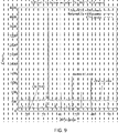
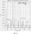
- Figures 9 , 10 , 11 , 12 , and 13 illustrate x-ray diffraction patterns of C3A, 82 wt.% C5A3, C12A7, CA, and CaO, respectively, before and after annealing in about 100 vol. % CO for about 15 hours at about 900 °C.
- the x-ray diffraction pattern illustrates no significant change even though the material converted from a white, electrically insulating powder to a dark, electrically conductive powder.
- These patterns indicate that the material underwent an electronic change like electride conversion or semiconductor doping, rather than a change in chemical stoichiometry or crystal structure.
- calcium aluminates C3A also known as celite
- CA change from white, electrically insulating powders to off-white, electrically insulating powders after being annealed in about 10-100 vol. % CO, in some embodiments about 100 vol. % CO to reduce annealing time) at about 1100-1300 °C, in some embodiments about 1200 °C, for about 0.1-30 hours, in some embodiments about 6 hours. This suggests an upper temperature limit for the conversion process.
- annealing C12A7 in a dry anoxic environment causes it to decompose to C5A3.
- the present invention relates in one embodiment to annealing C12A7 in a CO atmosphere for about 6 hours at about 1200 °C results in a dark, electrically conductive powder with a large mass fraction (over about 80 wt.%) of C5A3.
- Figure 9 illustrates x-ray diffraction patterns for the resulting darkened and conductive C5A3 electride powder. There are some peaks associated with CA and C12A7 in the pattern, but most of the peaks and peak area are associated with C5A3.
- C5A3 can also be made conductive by first converting C12A7 to C5A3 and then making the C5A3 conductive.
- the C12A7 was converted to C5A3 by annealing it in vacuum at about 1000 - 1200 °C (preferably 1100 °C) for about 1-12 hours (preferably 6 hours). This converts the C12A7 to about 80 wt.% C5A3 and 20 wt.% other calcium aluminates.
- phase pure C5A3 by annealing a mixture of C12A7 and Al 2 O 3 with C5A3 stoichiometry (about 0.015 g Al 2 O 3 for each 1.000 g C12A7) under the same conditions, but the product was still about 80 wt.% C5A3.
- the white, electrically insulating C5A3 could be converted to a dark, electrically conductive C5A3 by annealing in about 100 vol. % CO for about 15 hours at about 900 °C. This suggests that the C5A3 is being converted to a C5A3 electride in a manner similar to the C12A7 to C12A7:e- conversion.
- the compounds CA, C5A3, C3A, and CaO can be electrides or have some other conductivity mechanism at work (for example, oxygen vacancies). While not wishing to be bound by theory, the electrically conducting forms of C5A3, C3A, CA, and CaO can enhance NH 3 synthesis in the same manner that C12A7:e- does, but does not require an electrical bias. An electrical bias can be used. It is believed that the electrically conductive C5A3, C3A, CA, and CaO can also have low work function and the ability to incorporate hydrogen atoms as H - hydride ions like C12A7:e- does.
- the specific surface areas (surface area per unit mass) of C12A7, C5A3, C3A, CA, and CaO have all been increased by planetary ball milling with a nonaqueous solvent.
- Support materials can be made with specific surface areas.
- the surface area of the support material can range from about 1 to 100 m 2 /g, in some embodiments about 20 m 2 /g to 80 m 2 /g. In general, a higher specific surface area can be preferable as it allows more catalyst to be supported by a given mass of support.
- This method utilizes incipient wetness techniques and a ball milling technique to decorate the support materials with a metal material, such as Ru.
- Incipient wetness is a common decoration method in which a metal compound is dissolved in a solvent to form a solution, the support powder is wet with that solution, the solvent is allowed to evaporate from the support powder, and then the remaining dispersed metal compound is converted to metal by an appropriate anneal known by those skilled in the art.
- Ru carbonyl can be converted to Ru or Ru oxide by annealing in steps up to about 250 °C in either an inert or oxygen-containing atmosphere.
- RuCl 3 hydrate can be converted to Ru oxide or Ru metal in a similar way by annealing at 450 °C.
- the solvent used with the method to decorate the support material will depend upon the material being dissolved in the solvent. Thus, a comprehensive list of solvents is not possible. However, the material to be dissolved will be highly soluble in the solvent, land the solvent will evaporate quickly under the process conditions. Furthermore, the temperature and the atmosphere can be varied to achieve the desired results.
- the decoration process can be performed at room temperature and the solvent can be a non-aqueous solvent (since some of the materials will hydrate or change phase when an aqueous solution is used).
- non-aqueous solvents can typically be used with metal-organic compounds, while salts of the desired metal that have high solubility in water can typically utilize aqueous solvents. In either case, however, the solvent must also be compatible with the support material.
- the calcium aluminate and CaO support powders are all cement-formers, and thus are altered by water. Thus, a non-aqueous solvent must be used for incipient wetness Ru decoration. Ru carbonyl and RuCl 3 are not strongly soluble in organic solvents, which increases the amount of solvent that must be used and evaporated.
- the catalyst dispersion is the percentage of the catalyst atoms that are at a free surface and thus able to interact with the reactants.
- the catalyst dispersion can range from about 0.1% to about 90%, in some embodiments about 0.1% to about 50%.
- Catalyst dispersion of between about 40-60% dispersion, in some embodiments about 50%, dispersion corresponds to catalyst islands just a few nanometers in diameter.
- Catalyst decorated supports ranging from about 0.5 wt.% to about 20 wt.% metal, in some embodiments Ru, can be used.
- the catalyst decorated supports can range from 0.05 wt. % of the metal to about 5 wt. % of the metal.
- the metal dispersion decreases after a critical wt.% of the metal is exceeded because the metal starts to make larger islands instead of making more small ones, which is more desirable.
- the amount of catalyst supported can depend upon the support material. For example, calcium amide can support a higher weight of a metal than some other support materials while maintaining a high dispersion.
- catalyst loading is normally given in wt.%, that amount can be misleading when comparing different support materials or different catalysts because each material has a different molecular mass.
- iron molecular weight about 55.85
- ruthenium molecular weight about 101.1
- optimal catalyst loading is determined empirically. For example, if going from 1 wt.% Ru to 2 wt.% Ru only increases the activity by 25%, it may be more economical to use 25% more 1wt.% Ru decorated support in the reactor.
- Ru carbonyl or RuCl 3 hydrate powders are added to the support powder along with enough organic solvent, nonlimiting examples include acetone or heptane, to make a loose paste.
- This paste is milled in a ball mill, nonlimiting examples include a planetary ball mill, for between about 5 minutes to about 1 hour, in some embodiments about 30 minutes, and at a speed between 100 rpm to about 1000 rpm, in some embodiments about 400 rpm.
- the speed of the ball mill can depend upon the model of the ball mill used in the process.
- This method breaks up the Ru compound and disperses it on the support powder without requiring it to be fully dissolved in the solvent.
- the milled Ru + support paste can be baked or annealed using methods and parameters known to those skilled in the art for a particular metal compound to convert the Ru compound to Ru metal or Ru oxide.
- RuCl 3 hydrate is the preferred Ru compound because it is much cheaper than Ru carbonyl.
- this method can produce highly dispersed Ru, in some embodiments a dispersion up to about 90%, it also causes the conductive support powder to become non-conductive, likely due to surface damage on the powder particles. Exposing the electrically conductive support powders to the Ru compound and solvent without milling does not remove its conductivity, and milling the conductive support powders without the Ru compound does remove its conductivity. The powder still retains its dark color, and therefore is still an electrically conductive core surrounded by a more insulating shell, which can be suitable to the NH 3 synthesis enhancement.
- the insulating shell can be beneficial to electrical enhancement because it will allow the CO-annealed powder to be used in an electric field mode as the insulating powder would not short circuit the capacitor plates. If the insulating shell still allows hydride ion transport and/or retains features that foster N 2 activation, it can be beneficial.
- the catalyst-decorated electride's ability to catalyze NH 3 can be tested at the lab scale in a small differential reactor.
- One skilled in the art would understand that a laboratory model can be scaled up.
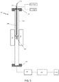
- FIG. 5 A schematic diagram of an embodiment of a reactor is illustrated in Figure 5 .
- the reactor 100 used in the design of the invention was a "tube in a tube” design in which the outer tube 102 is a pressure vessel and the inner tube 104 directs gas flow through an interchangeable cup 106 that contains the catalyst.
- Hydrogen and nitrogen gas are admitted to the reactor by mass flow controllers connected to the inlet flange 108 of the reactor.
- the nitrogen and hydrogen flow rates can maintain a desired gas mixture, NH 3 production rate, NH 3 concentration, space velocity, or linear gas velocity in the reactor.
- a thermocouple 110 that measures the catalyst temperature and electrical connections that provide bias 112 to the catalyst also enter the reactor 100 through feedthroughs in the inlet flange 108.
- the central portion of the reactor 100 is heated with heaters.
- the heaters can be insulated resistive heaters 120 that can heat the reactor 100 from room temperature to about 650°C.
- the temperature in the reactor can be between about 300°C and about 600°C. In some embodiments, the temperature in the reactor can be between about 450°C and about 480°C.
- the product gases exit the reactor 100 through the outlet flange 114.
- the pressure in the reactor 100 is monitored downstream of the outlet flange with a pressure sensor 116.
- the reactor pressure can be controlled by a backpressure regulator 118 located downstream of the pressure sensor 116 that can raise the reactor pressure to about 150 psig (1034.21 kPa). This pressure was chosen to ensure that at high temperature operation softening of the reactor's outer wall would not cause it to rupture.
- a practical upper limit to the reactor pressure is the pressure at which the NH 3 condenses to a liquid. NH 3 condensation can cause inaccurate NH 3 production measurements or compromise the operation of the reactor.
- the specific total pressure at which NH 3 condensation will occur depends on the NH 3 concentration in the reactor and the reactor temperature. In some embodiments, the pressure can be between about 0 and about 140 psig (965.266 kPa). Higher pressures can result in higher synthesis rates.
- Product gases exiting the backpressure regulator 118 are at ambient atmospheric pressure. The product gas NH 3 concentration is measured by a device downstream of the backpressure regulator 118. The product gases can be flared (i.e. ignited) to convert the NH 3 and any unreacted N 2 and H 2 reactants to nitrogen and water so they can be safely exhausted to atmosphere for disposal.
- the inner tube 104 of the reactor 100 extends from the bottom side of the inlet flange 108 to near the center of the reactor 100, where it terminates in a flange.
- An interchangeable cup 106 containing the catalyst-decorated electride support is attached (e.g. bolted, adhered, etc.) to that flange.
- the cup 106 can be easily changed to allow changes to its size, shape, and electrode configuration. While Figure 5 illustrates the cup near the center of the reactor, this position is not required. Rather, the cup simply needs to be in a region with uniform temperature.
- the cup diameter can be adjusted so that the gas flow rates produce a linear gas velocity that removes stagnation layers from the catalyst-decorated support particles.
- the length of the cup can also be adjusted for a given diameter so that the cup contains enough catalyst to produce a measured concentration of NH 3 . In some embodiments, between about 0.1 grams and about 50 grams of the catalyst can be used in the cup.
- the bottom of the cup 106 can be porous to allow gas to flow through it. In operation, the reactant gases flow through the inner tube 104, through the catalyst-decorated electride support in the cup 106, and out the outlet flange 114 of the reactor 100.
- the inner tube 104 and cup 106 can be electrically isolated from the rest of the reactor 100 by using an electrically insulating gasket and ceramic bolt sleeves at the inner tube's attachment to the inlet flange 108.
- Suitable materials for the insulation can include Kevlar fiber reinforced BUNA rubber gasket materials, or other suitable materials. Any suitable material can be used for the reactor flanges, tubing, walls, and catalyst cup. In some embodiments, the material can be stainless steel or a non-stainless steel alloy. Some or all of the reactor can be coated for corrosion protection. In general, materials selected for the reactor are compatible with NH 3 . Steel is a cheap option, as are most ceramics and BUNA elastomer seals. Specific incompatible materials are copper alloys, aluminum alloys, and viton elastomer seals.
- Figure 6 illustrates a configuration of the catalyst cup featuring concentric cylindrical electrodes in an embodiment of the invention.
- the top and bottom of the electrodes 614 e.g. A-D
- the electrodes can be supported by ceramic disks 610.
- the ceramic disks 610 can maintain electrode separation and support the electrodes and fiber materials that keep the catalyst-decorated electride support from falling through the gas flow openings in the ceramic discs.
- Support tabs 612 can be used to support the ceramic disks 610.
- the minimum separation will be limited by the ability to put catalyst powder between the electrodes and the ability to keep the electrodes from touching each other if they warp when heated.
- the spacing can be a minimum of about 1 mm.
- the maximum spacing can be limited when the reactor is in field enhancement mode as this mode requires electrodes capable of applying a sufficient electric field given power supply voltage limitations.
- the electrode spacing can be adjusted to allow easy loading of catalyst-decorated electride support between the electrodes and generation of the desired electric field strength (V/cm) for the available voltage. For example, if the desired field strength is about 20,000 V/cm peak to peak and the available power supply outputs about 2000 V peak to peak, then the electrode separation needs to be about 0.1 cm.
- a center threaded electrode rod 602 can be used to clamp the ceramic disks rigidly to the cylindrical electrodes and secured with a nut or fastener end 604.
- the ceramic disks have holes in the regions between the electrodes 608 to allow gas to flow through the catalyst-decorated electride support. Wires extend from the electrodes through the upper ceramic disk to allow electrical bias to be applied to them.
- a dopant is not required to increase the conductivity of the system. Rather, the wires can be attached to the electrode, for example by welding, soldering, or contact with fasteners.
- the cup flange 620 connects the cup 106 to the inner flange illustrated in Figure 5 .
- the cup wall 616 provides an exterior surface of the cup 106 and can act as an electrode using electrode connection A.
- the ceramic fiber 618 is porous enough to allow gases to flow through it, but dense enough to prevent the catalyst-decorated electride support from falling through the gas flow openings in the ceramic disks 610.
- the catalyst cup implementation illustrated in Figure 6 allows the catalyst to be tested (a) without any bias, (b) in a non-current-passing NEMCA-mode electrically enhanced configuration if an electrically conductive catalyst is used and the cup and its electrodes (A, B, C, D, E) are all connected to a voltage source that applies a voltage relative to the grounded reactor body, (c) a current-passing NEMCA-mode electrically enhanced configuration if an electrically conductive catalyst is used and the electrodes are alternately connected to the positive and negative outputs of a power supply (for example electrodes A, C, and E connected to the positive potential and electrodes B and D connected to the negative potential), and (d) a field-mode electrically enhanced configuration if an electrically non-conductive catalyst is used and the electrodes are alternately connected to the positive and negative outputs of a power supply (for example electrodes A, C, and E connected to the positive potential and electrodes B and D connected to the negative potential).
- the catalyst cup implementation illustrated in Figure 6 can be modified by replacing electrodes B and D with electrical insulators (for example, ceramic cylinders).
- electrodes A and E can be connected to the positive output of a power supply and electrode C can be connected to its negative output (or vice versa).
- An electrically conductive catalyst-decorated support can be placed between each of the cylinders. When an electrical bias is applied, charge can be moved from the catalyst-decorated support in spaces A-B and C-D to that in spaces B-C and D-E.
- a NEMCA-mode electrical enhancement can be achieved by applying an AC, pulsed DC, or arbitrary waveform between the power supply terminals.
- This waveform can alternately enhance H 2 activation, N 2 activation, or intermediate species formation, causing the overall NH 3 synthesis rate to be increased.
- the catalyst-decorated electrically conductive support in each space can alternately act as a counter electrode or working electrode as the applied potential changes in time.
- the C12A7:e- electride can act as a support for any NH 3 catalyst.
- a catalyst can decorate the support (i.e. applied to the surface of the support).
- the catalyst can include, but is not limited to, a metal oxide, a metal nitride (cobalt molybdenum nitride, for example), a metal (including promoted iron), an alkali promoted iron catalyst, and combinations thereof.
- the catalyst can be a metal oxide, such as an iron oxide.
- the catalyst can contain a metal, for example any Group VIII metal, such as ruthenium, iron, osmium, nickel, palladium, platinum or combinations thereof.
- the catalyst can be an alkali promoted metal oxide catalyst, for example an iron oxide potassium oxide catalyst.
- the catalyst can be an alkali promoted metal catalyst, for example Cs promoted Ru metal.
- a "promoted" catalyst refers to an added material to the catalyst that results in the catalyst having a higher activity.
- alkali metals Cs, K, Na, etc.
- Ru or Fe alkali metals
- the alkali metals do not do not catalyze NH 3 synthesis on their own, rather these metals help Fe and Ru work better.
- the amount of catalyst-decorated electride support used can depend on the reactor and the desired production rate. By way of non-limiting example only, in some embodiments, between about 0.01-2 kg of catalyst can be used.
- Lab testing of the catalyst-decorated electride support can examine reagent flows, N 2 :H 2 ratios, total pressures, temperatures, and electrical enhancement parameters such as applied voltage, applied electric field strength, and the frequency and form of time-varying applied voltages and electric fields.
- the test parameters can be chosen to ensure high reaction site availability and thus accurate measurement of the reaction rate.
- the reagent flow rate should be high enough that further increases in flow rate do not cause increased NH 3 synthesis rate. Under that condition, the reaction rate is only limited by the catalytic activity, rather than diffusion through a gas stagnation layer around the catalyst-decorated support particles.
- optimal H 2 :N 2 ratios can range from about 3:1 to about 1:1.
- the total pressure can be adjusted in combination with H 2 :N 2 ratios to create different reagent partial pressures to elucidate the partial pressure dependence of the rate law.
- Temperature can range from room temperature to about 650 °C, although experiments suggest a preferred range of about 350-500 °C. This configuration is chosen because it is much more difficult to elucidate reaction kinetics using integrated rate laws, and accurate reaction rate information is essential to larger reactor modeling.
- the rate parameters can be determined by regression of the experimental data.
- Reaction kinetics can initially be measured without electrical bias. Catalysts with good performance without electrical bias can then be tested with NEMCA-mode or field-mode electrical enhancement.
- NEMCA when NEMCA is used, the process can begin with a DC "no current" configuration, which would apply a potential to the catalyst relative to ground.
- a current-flowing configuration which is between adjacent plates, can be used. Once a flow has been established, then the current can be steady or pulsed.
- a pulsed DC potential can have a larger NEMCA effect than a DC potential because it can temporally organize the intermediate reactions.
- one potential may be optimal for removing H atoms from the Ru islands by converting them to trapped H -
- another may be optimal for injecting electrons from the Ru into the N 2 to weaken its triple bond
- a third might be optimal for fostering reactions between trapped H - and excited N 2 to form NH 3 .
- the net reaction rate can be increased by first maximizing N 2 adsorption on the Ru, then maximizing electron injection to the adsorbed N 2 , and then maximizing excited-state N 2 conversion to NH 3 .
- an optimum sinusoidally varying AC frequency is used for field-mode electrical enhancement
- further optimization can be achieved by altering other wavefunctions such as triangle waves, square waves, stepped waves, and arbitrary wavefunctions.
- an arbitrary wavefunction can have a larger electric-field-enhancement effect than a sinusoidal one because it can provide different field strengths and durations to temporally organize the specific intermediate reactions for NH 3 formation. It is likely that the optimal peak-to-peak amplitude and frequency will depend on the specific wavefunction.
- NH 3 can be harvested by condensing it from a product gas or absorbing it into a material or filtering it from a product gas.
- the material can absorb the NH 3 , which can be for example, MgCl 2 .
- Such reactors can also add nitrogen and hydrogen gas via the inlet to maintain the reactor pressure.
- Reactors intended for production of NH 3 can be operated at higher pressures to both increase the NH 3 synthesis rate and increase the temperature at which the NH 3 can be liquefied, adsorbed, or absorbed for extraction from the product stream.
- Such reactors can use internal heating of the catalyst to allow the reactor walls to operate at a lower temperature by being either actively or passively cooled. This can help maintain their structural strength and ability to contain higher operating pressure.
- the lab-scale differential test reactor described above has been used to test the non-electrically enhanced NH 3 synthesis capability of Ru-decorated C12A7:e-.
- the catalyst support was a -45 mesh powder with a surface area of 6.2 m 2 g -1 as measured by nitrogen BET analysis. Its surface was decorated with 1 wt.% Ru with 26% dispersion as measured by pulsed CO chemisorption.
- the catalyst cup used for the measurement was that shown in Figure 6 , but with the electrode assembly removed.
- the bottom of the cup was fit with a stainless steel screen.
- a 6 mm layer of ceramic fiber insulation was placed on top of the screen to support the catalyst powder.
- the cup was loaded with 5.081 g of catalyst, which created a catalyst bed approximately 1.5 cm deep.
- the reactor was run at a total pressure of 140 psig (965.266 kPa) and a total flow of 4 sLm (3.776 NLPM).
- the H 2 :N 2 ratio was successively maintained at nominal values of 3:1, 2:1, 1.5:1, and 1:1.
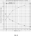
- the reactor's internal temperature was ramped from approximately 400 °C to 500 °C at a rate of 50 °C h -1 while the rate of NH 3 formation was monitored by a non-dispersive infrared sensing method (Bacharach model AGMSZ detector). The data from the measurements is illustrated in Figure 7 .
- the lab-scale differential test reactor described above was used to test the total flow rate dependence of non-electrically enhanced NH 3 synthesis on Ru-decorated C3A support.
- the C3A support was a -45 mesh powder with a surface area of 3.6 m 2 g -1 as measured by nitrogen BET analysis. Its surface was decorated with 5 wt.% Ru with 1% dispersion as measured by pulsed CO chemisorption.
- the catalyst cup used for the measurement was that illustrated in Figure 6 , but with the electrode assembly removed.
- the bottom of the cup was fit with a stainless steel screen.
- a 6 mm layer of ceramic fiber insulation was placed on top of the screen to support the Ru-decorated C3A support powder.
- the cup was loaded with 5.040 g of catalyst, which created a catalyst bed approximately 1.5 cm deep in the 2.7 cm internal diameter cup.
- the reactor was run at 470 °C, 140 psig (965.266 kPa) total pressure, and a 2:1 H 2 :N 2 ratio.
- the stabilized NH 3 synthesis rate and product gas NH 3 concentration was measured at a series of total gas flows. The data from the measurements is illustrated in Figure 8 .
- the NH 3 synthesis rate increased monotonically with flow rate, and was approximately 13.2 mmol g -1 h -1 at 10 sLm (9.44 NLPM) total flow.
- the NH 3 concentration at that flow was approximately 2.8 ppt, well below the equilibrium value of approximately 5% (50 ppt). This data suggests that the NH 3 synthesis rate was being limited by diffusion across a stagnation layer surrounding the catalyst-decorated support particles. Removal of that stagnation layer will require flow rates higher than 10 sLm (9.44 NLPM) if the 27 mm internal diameter catalyst cup is used.
- the 2.7 cm internal diameter catalyst cup has a linear gas velocity of 29.1 cm/s at 10 sLm (9.44 NLPM).
- An alternative to increasing the flow rate to increase the linear velocity is to decrease the catalyst cup's cross-sectional area. For example, if the cross sectional area is reduced by a factor of 3 (diameter reduced by a factor of 3 1/2 ), the gas linear velocity will be increased by a factor of 3 at the same total flow.
- NH 3 synthesis rates have been measured on Ru-decorated CO-annealed supports where the supports consisted of CA, C5A3, C3A, C12A7, and CaO (calcium oxide, C in cement chemistry notation).
- Table 2 shows the conditions for each support that have produced the highest NH 3 synthesis rates at 4 sLm (3.776 NLPM) total flow.
Landscapes
- Chemical & Material Sciences (AREA)
- Organic Chemistry (AREA)
- Chemical Kinetics & Catalysis (AREA)
- Engineering & Computer Science (AREA)
- Materials Engineering (AREA)
- Inorganic Chemistry (AREA)
- Analytical Chemistry (AREA)
- Physics & Mathematics (AREA)
- Thermal Sciences (AREA)
- Catalysts (AREA)
- Organic Low-Molecular-Weight Compounds And Preparation Thereof (AREA)
Description
- This invention relates to increasing the rate of ammonia (NH3) synthesis from nitrogen gas N2 and hydrogen gas H2 on a catalyst-decorated electride support.
- An energy system that is free of fossil fuel carbon dioxide (CO2) emissions is required to prevent the continued rise in atmospheric CO2 while allowing for all of humanity to enjoy the same living standards those in the developed western world enjoy. While there are several well-developed CO2-free energy generation options (e.g. wind, solar, hydro, nuclear), none presently have a well-developed CO2-free fuel option. Ammonia can fill this need.
- NH3 can be burned directly as a fuel in reaction of Equation (1):

- It can also be used as a hydrogen storage medium if it is thermally reformed into hydrogen and nitrogen. In principle, NH3 can be used as a CO2-free fuel. However, nearly all current NH3 production uses CO2-producing feedstock and fuel.
- Modern Haber-Bosch plants use approximately 31.4 GJ natural gas (feed and fuel) per ton of NH3 produced. Haber-Bosch NH3 synthesis for fertilizer currently uses between about 3-5% of global natural gas production and between about 1-2% of global energy production. In 2005, the average CO2 emissions for Haber-Bosch NH3 synthesis was 2.1 tonnes CO2 per tonne NH3, of which 2/3 was from steam reforming hydrocarbons to produce hydrogen and 1/3 was from fuel combustion to provide energy to the synthesis plants. At that time, approximately 3/4 of Haber-Bosch NH3 plants used natural gas, while the rest used coal or petroleum for feed and fuel.
- Modern Haber-Bosch plant efficiency is maximized by running at a steady state. This requirement for efficiency makes it difficult to directly couple its operation to the energy produced by wind and solar power plants, which have a variable power output.
- The Haber-Bosch process for producing NH3 is exothermic reaction shown in Equation (2).

- The reaction occurs in a reactor containing an iron oxide or ruthenium catalyst at 300-550 °C and 90-180 bar pressure. The elevated temperature is required to achieve a reasonable reaction rate. Due to the exothermic nature of NH3 synthesis, the elevated temperature drives the equilibrium toward the reactants, but this is counteracted by the high pressure. In commercial production, waste heat from ammonia synthesis contributes to hydrogen production by steam reforming natural gas.
- Electrides can be used as a catalyst support in a Haber-Bosch reaction. An electride is an ionic material in which trapped electrons play the role of negatively charged ions. C12A7:e- calcium aluminate electride is the first air-stable and temperature-stable electride that has been produced. C12A7:e- is a relatively new material, having been first produced in 2003. Its positively charged framework forms cages that contain electrons. Its chemical structure is [Ca24Al28O64] 4+(e-)4. The "C12A7" designation is cement chemistry nomenclature, in which C refers to CaO and A refers to Al2O3. The ":e-" designation signifies that the C12A7 has a portion of its oxygen anions replaced by electrons, defining it as being an electride. A proposed NH3 synthesis pathway for electride-supported ruthenium (Ru) is illustrated in
Figure 1. Figure 1 can be found in Kitano et al., "Ammonia Synthesis using a stable electride as an electron donor and reversible hydrogen store." Nature Chemistry 4 934-940 (2012). The reaction starts in the top image (N2 and H2 adsorbing onto a Ru island) and proceeds clockwise. The steps in the process are: (1) H2 on the Ru islands dissociate into H; (2) H enter the electride and react with trapped e- to form H-, making room for N2 adsorption; (3) trapped e- transfer to N2 antibonding orbitals via the Ru, putting the N2 in an excited state (triple bond weakened); and (4) weakly bonded N2 near the edge of the Ru islands react with H- in the electride, transferring e-back to the electride and transferring H to the excited-state N2 to form NH3 or its intermediates. Electride-supported Ru has an activity 10x larger than other Ru-loaded catalysts. The electride is critical to speeding the formation of weakly bonded N2 by (a) removing H from the Ru surface so there is area available for N2 to react, and (b) supplying e- to the Ru d-orbitals for transfer to the N2, which weakens its triple bond. The use of C12A7:e- in traditional Haber-Bosch NH3 synthesis is the subject ofUS Publication No. 2013/0183224 .US 2015/239747 Al discloses a process for making ammonia, a corresponding reactor and a method for making an electride supported catalyst. The ammonia process comprises reacting N2 and H2 over a catalyst comprising a C12A7 electride coated with Ru at 320-400°C. The ammonia reactor comprises a fixed bed reactor and a glass tube filled with an electride supported ruthenium catalyst. - It has been demonstrated that the activity of a catalyst can be modified by applying electricity to it. Two methods of electrically enhancing catalytic activity are (1) "Nonfaradaic Electrochemical Modification of Catalytic Activity" (NEMCA) and (2) the direct application of electric fields to the catalyst by placing it between the electrodes of a capacitor. In NEMCA, catalyst activity is increased by the application of an electric potential to the catalyst. That potential may or may not drive a current. If it does drive a current, the reaction rate is greater than is indicated by the passed current. It is attributed to the catalyst work function changing as ion position and energy are modulated by the applied potential. A state-of-the-art commercial promoted-Fe NH3 catalyst exhibited up to a 13x increase in activity due to NEMCA (
Figure 2). Figure 2 can be found in Yiokari et al., "High-pressure electrochemical promotion of ammonia synthesis over an industrial iron catalyst." J. Phys. Chem. A 104 10000-10002 (2000). As described in Yiokari, the NH3 catalyst was applied to one side of a proton-conducting ceramic and a silver paste was applied to the other side. The reactor was run at 440°C or higher and 50 atm total pressure (720 psig or 4964.23 kPa). A -1 V potential was applied between the catalyst and the silver counter-electrode, which drove protons through the proton conducting ceramic to the catalyst. In that situation, H2 dissociation occurs on the silver counter-electrode and NH3 formation occurs on the commercial NH3 catalyst. - Catalytic activity may also be enhanced by the application of a time-varying electric field in a capacitive manner. This approach was described for converting CO to CO2 over a NiO catalyst and for converting benzene to cyclohexane over a brass catalyst in
US Patent 3,519,546, entitled "Method of Increasing the Activity of a Catalyst in the Oxidation of Carbon Monoxide" to Lee ("Lee"). Lee discloses a method to enhance the activity of a solid catalyst with a time varying electric field on the surface. The Lee process requires the surface of the catalyst be in contact with a liquid or gaseous chemical reactant. Lee demonstrated field enhancement of the reactions CO → CO2 on an oxidized Ni surface, and benzene → cyclohexane on a brass surface. In both cases, the capacitor surface was the catalytic material. Data from Lee is illustrated inFigure 3 , and shows an increase in conversion of CO to CO2 varied with the frequency of the applied electric field, reaching a factor of 6.3 increase in conversion in a 100 Hz 22,000 V/cm electric field. The data inFigure 4 illustrates that the increase in conversion of benzene to cyclohexane varied depending on both the peak-to-peak field strength and the field frequency. The conversion was increased by a factor of 3.2 in a 1,300 Hz 1,000 V/cm electric field. - Prior efforts at sustainable fuel production have focused on biofuels, H2, and "artificial photosynthesis." Although ethanol and biodiesel both have higher energy density than NH3, using food resources for fuel production results in higher food prices by both shifting the allocation of cropland from food to fuel and by raising the prices of the crops used for fuel production. This reallocation can cause political instability in developing countries due to higher food prices.
- Hydrogen has never been able to overcome its storage density problems, although NH3 can be regarded as a solution to H2 storage. NH3 has ~2x the energy density of liquid hydrogen at easily achieved pressures and temperatures (9 atm at 25 °C; 1 atm at -33 °C).
- Although "artificial photosynthesis" could make a closed loop fuel cycle, it must extract CO2 from the air to do so. NH3 is a more viable route because of its high atmospheric concentration (79% for N2, 0.04% for CO2). Due to this difference in concentrations, synthesizing 1 mol of CH4 requires processing 3,550 times as much atmosphere as synthesizing 1 mol of NH3. That adds equipment and energy expense to CH4 synthesis compared to NH3. Furthermore, commercial air separators for atmospheric N2 extraction already exist.
- The lower heating value (LHV) and H2 density for NH3 and other fuels is shown in Table 1. NH3 has roughly half the volumetric energy density of gasoline, and nearly twice that of liquid hydrogen. Its high hydrogen density (0.136 kg/L, 17.6 wt.% H2) exceeds the Department of Energy's 2015 FreedomCAR targets (0.040 kg/L and 5.5 wt.% H2).
Table 1 Fuel LHV (MJ/kg) LHV (MJ/L) H2 (kg/L) NH3 18.6 14.1 0.136 Gasoline 42.5 29.8 0.110 Ethanol 27.0 21.1 0.102 Liquid hydrogen 120 8.4 0.070 - One object of the present invention is related to a fast-ramping NH3 reactor that uses Electrically Enhanced Haber-Bosch (EEHB) to produce NH3 by using nitrogen from the air, hydrogen from water, and energy from wind, solar, or nuclear power plants, and this will reduce or eliminate CO2 emissions from NH3 production. EEHB uses an electrically enhanced, catalyst-decorated electride support to increase NH3 catalytic activity up to 130x that of a traditional Haber-Bosch reaction. The present invention can transform solar and wind power plants from facilities that must be accommodated by the grid into facilities that provide fuel for the grid and transportation. Advantageously, large and small scale wind and solar power plants can use the present invention to produce their own fuel for backup power generation to buffer intermittency, sell the NH3 as a CO2-free fuel or fuel additive, or sell the NH3 as a CO2-free fertilizer feedstock. This new ammonia source can open markets for stranded electricity generation, enable remote energy systems that need no fossil fuel for backup power, and eventually provide CO2-free fuel for grid peaking power plants and transportation applications.
- While not wanting to be bound by theory, the inventors believe that catalyst-decorated electride support will display a significant NEMCA effect and electric field enhancement effect due to the high mobility of the electride's intrinsic e- and reaction-produced H- anions. NEMCA is thought to improve the activity of other NH3 catalysts. Other reactions have shown NEMCA reaction rate enhancements up to 5 orders of magnitude. The present invention exploits this characteristic by either applying a DC, pulsed DC, or AC bias to the catalyst-decorated electride support; or applying a time-varying electric field to the catalyst-decorated electride support. In either case, the applied voltage or electric field increases the catalyst activity by modifying the electron energies at the catalyst surface. The applied voltage or electric field can increase reaction rates by one or more of the following: enhancing e- transfer to the catalyst and/or N2, promoting H removal from the catalyst by easing H- formation and incorporation into the electride, or promoting NH3 formation by shifting H- energy at the catalyst-electride interface. This process can increase the activity of EEHB reactors by orders of magnitude compared to traditional Haber-Bosch reactors.
- The present invention differs from prior art systems and methods because the present invention enhances Haber-Bosch reactions/reactors with the use of electrical enhancements. Prior art systems and methods do not apply electrical potentials or fields to the Haber Bosch reactions/reactors.
- Furthermore, unlike Yiokari, dissociation of hydrogen and NH3 synthesis of the present invention does not occur at macroscopically separate locations. Also unlike the method described in Yiokari, the method described herein does not use a proton conductor.
- Unlike Lee, the reaction of the present invention is a NH3 synthesis and the catalyst is a powder placed between the capacitor plates. The plates are not intentionally catalytic material. Rather, they can be steel or another conductor compatible with the NH3 synthesis environment.
- The electride support significantly increases Ru catalytic activity, in some instances by up to about 10-fold over current commercial NH3 catalysts used in the traditional Haber-Bosch NH3 synthesis process. The catalyst activity is further "electrically enhanced" using the NEMCA effect or by applying an electric field to the catalyst-decorated support. NEMCA-mode electrical enhancement of the catalyst activity uses either a DC, pulsed DC, AC, or arbitrary waveform potential. Field-mode electrical enhancement of the catalyst activity use time-varying electric potential suitable to produce a time-varying electric field in the catalyst-decorated support located between capacitive elements.
- There can be multiple uses for the NH3 produced using the present invention. For example, pure NH3 can be run in spark-ignition internal combustion engines by employing a catalytic cracker to decompose a small fraction of the NH3 into N2 and H2 prior to it entering the combustion chamber. This use has been demonstrated in a working hybrid electric waste disposal truck in Italy. Mixtures up to 20% NH3 + 20% methanol + 60% gasoline perform well in current unmodified gasoline engines. "Flex Fuel" engines will allow use of higher NH3 concentrations. Shifting the US vehicle gasoline supply to a 20% NH3 + 20% methanol + 60% gasoline blend will reduce gasoline vehicle CO2 emissions by 11% with small changes to the existing fleet fuel tank and fuel lines. If future ground transportation engines are required to use NH3 fuel, then CO2 emissions from ground transportation will eventually drop to zero as the vehicle fleet turns over.
- Models of US electricity grids show that short-term energy storage (batteries, pumped hydro, compressed air) equal to 1 day of average use will allow 80% of electricity to come from variable sources. In that model, the remaining 20% of the electricity is provided by fast-ramping gas turbines. If EEHB reactors are used to make NH3 fuel to power the turbines instead of natural gas, then CO2 emissions from grid electricity generation will fall to zero.
- NH3 is safely stored in either ambient temperature or refrigerated tanks and it is routinely transported by rail, road, and pipeline. The US has over 3,000 miles (4828.032 km) of existing NH3 pipeline. Bulk liquid NH3 is currently stored at 1 atm at -33.3 °C in large insulated steel tanks with 50,000 tonne capacity. Smaller amounts are stored in mild steel tanks at approximately 10 atm.
- An engineering analysis of the hazards of NH3 and liquefied natural gas concluded that they posed similar hazard levels. NH3 vapor is lighter than air, so it quickly dissipates upward in the event of a spill. It has narrow flammable and explosive ranges and a high minimum ignition energy, further reducing its risk. In contrast, natural gas is heavier than air and has a wide explosive range. These characteristics make natural gas a major fire and explosion hazard when it leaks.
- NH3 and its combustion products are not greenhouse gases. Inhalation of high concentrations of NH3 vapor (much higher than the olfactory threshold) can cause lung damage due to formation of ammonium hydroxide, but it is not poisonous in the toxicological sense. Its odor is easily recognized at nonhazardous concentrations, causing small leaks to be quickly noticed. It is not carcinogenic. It is biodegradable, posing no long term risks to water supplies if it leaks underground. Its characteristics are relatively benign compared to petroleum fuels.
- EEHB's electrical enhancement can run in a more dynamic way than the traditional thermal-only Haber-Bosch process. This adaptability can allow EEHB reactors to better follow the ups and downs of variable energy production from wind and solar resources. Haber-Bosch synthesized NH3 that uses H2 electrolyzed from water instead of steam reformed from natural gas requires about 12,000 kWh of electricity per tonne of NH3 produced. If the EEHB process has a higher catalytic activity and is more energy efficient than Haber-Bosch, then the energy requirement can be lower than that. If the EEHB system uses electricity from non-CO2-emitting sources, it will produce fertilizer and fuel with no CO2 emissions as compared to 2.1 tonnes CO2 per tonne NH3 for Haber-Bosch synthesis using steam reformed hydrogen.
- An aspect of the invention is a method of enhancing the production rate of NH3 on an electride-supported metal catalyst as defined by
claim 1. Preferred and optional features are defined independent claims 2 to 6. - Another aspect of the invention is a reactor for producing ammonia from nitrogen and hydrogen gas with a supported catalyst as defined by
claim 7. Preferred and optional features are defined byclaims 8 to 10. -
-
Figure 1 illustrates NH3 formation on electride-supported catalyst (from Kitano); -
Figure 2 illustrates the NH3 synthesis rate on commercial iron oxide based catalyst without bias and with -1 V NEMCA bias (from Yiokari); -
Figure 3 illustrates the increase in CO oxidation as a function of frequency for a 22,000 V cm-1 electric field (data from Lee); -
Figure 4 illustrates the increase in conversion of benzene to cyclohexane for different electric field strengths and frequencies (data from Lee); -
Figure 5 illustrates a schematic diagram of the EEHB lab-scale test reactor; -
Figure 6 illustrates a version of the replaceable catalyst cup that can be used for unbiased, NEMCA-mode electrically enhanced, and field-mode electrically enhanced NH3 synthesis measurements; -
Figure 7 illustrates the performance of Ru-decorated C12A7:e- in the lab-scale test reactor; -
Figure 8 illustrates stabilized NH3 synthesis rate as a function of total reactor flow rate. -
Figure 9 illustrates the x-ray diffraction patterns of C3A before and after being annealed in CO; -
Figure 10 illustrates the x-ray diffraction patterns of C5A3 before and after being annealed in CO; -
Figure 11 illustrates the x-ray diffraction patterns of C12A7 before and after being annealed in CO; -
Figure 12 illustrates the x-ray diffraction patterns of CA before and after being annealed in CO; and -
Figure 13 illustrates the x-ray diffraction patterns of CaO before and after being annealed in CO. - The present invention is directed to a method to produce NH3 using EEHB, and the materials and apparatus used therein. More specifically, and as provided in greater detail below, this is accomplished using an electride supported catalyst in the reactor. An electrical bias or a time-varying electrical field is applied to the reactor. Methods for making the electride support and electride supported catalyst, not falling under the scope of the claims, are also provided.
- The common method for making C12A7:e- powder involves making an off-stoichiometry powder, adding Ca metal to it, and annealing in vacuum. During the process, the white, insulating, off-stoichiometry powder becomes a dark, electrically conductive, C12A7:e- electride. It is recognized in the catalyst industry that this method of C12A7:e- cannot be readily scaled up for mass production. The prior art method for making single crystal C12A7:e- are generally taught by placing a single crystal of C12A7:O (C12A7 with oxygen anions in its cages, rather than electrons) at ambient atmosphere in a closed carbon crucible and annealing it in a tube furnace purged with inert gas at around 1200 C for 10-15 h. The anneal caused the single crystal to change from clear to green and develop a charge carrier concentration around 1019 cm-3.
- The present invention is directed to a scalable method for producing C12A7:e-powder. It was found that annealing C12A7:e- powder in controlled CO atmospheres at 900 C for 15 h caused it to darken and become conductive while retaining the C12A7 crystal structure. Annealing at 100% CO for 15 h at 900 C caused complete conversion to C12A7:e-, producing material with the theoretical maximum charge concentration for this material. Annealing at CO concentrations less than 25% caused the C12A7 powder to darken progressively less and not become measurably conductive. Although it was not measured, it is likely that CO concentrations between 25% and 100% cause intermediate charge carrier concentrations.
- Furthermore, and in one aspect of the invention, it was found that annealing other calcium aluminates in an environment of about 5 vol. % to about 100 vol. % CO, in some embodiments about 100 vol. % CO (which reduces the required annealing time) at between about 600 °C and about 1100 °C, in some embodiments about 900 °C (which quickly results in a conductivity change while minimizing or eliminating the chance of calcium aluminate phase change) for about 0.1 to about 30 hours in some embodiments between about 1-15 hours (which maximizes the high carrier concentration while minimizing or eliminating the chance of causing unwanted calcium aluminate phase changes) also causes them to change from white, electrically insulating powders to dark, electrically conductive powders while retaining their original crystal structure. In addition to C12A7, this behavior has been observed in CA, C5A3, and C3A (known as celite) calcium aluminates. The rate of conversion of the C12A7 powder to an electride is dependent upon the parameters such as the concentration of a reducing agent (in this example, CO can be used as a reducing agent, though other reducing agents can also be utilized without deviating from the invention), the temperature of the reaction and the time of the reaction. The lower any of these parameters are, then the longer the conversion reaction will take. Other calcium aluminate powders can also be used, including CA, C3A, and C5A3, and combinations thereof.
- Annealing CaO (calcium oxide, C in cement chemistry notation) in about 5 vol. % to about 100 vol. % CO, in some embodiments about 100 vol. % (which reduces the required annealing time) at between about 600 °C and about 1100 °C, in some embodiments about 900 °C (which results in a quick quickest conductivity change while minimizing the chance of phase change) for about 0.1 to about 30 hours, in some embodiments about 1-15 hours (which maximizes the high carrier concentration while minimizing the chance of causing unwanted phase changes) converts it from a white, insulating powder to a dark, electrically conducting powder while retaining its original crystal structure. This material is mentioned separately from CA, C3A, C5A3, and C12A7 because it is not, strictly speaking, a calcium aluminate. However, it responds to the CO anneal in a similar manner as the calcium aluminates.
- In the case of C12A7, annealing in hydrogen does not cause C12A7:0 to fully convert to C12A7:e- like annealing in CO does. A reducing agent with similar Gibbs free energy as a function of temperature as CO should also cause conversion of calcium aluminates and CaO from electrically insulating to electrically conductive materials.
-
Figures 9 ,10 ,11 ,12 , and13 illustrate x-ray diffraction patterns of C3A, 82 wt.% C5A3, C12A7, CA, and CaO, respectively, before and after annealing in about 100 vol. % CO for about 15 hours at about 900 °C. In each case, the x-ray diffraction pattern illustrates no significant change even though the material converted from a white, electrically insulating powder to a dark, electrically conductive powder. These patterns indicate that the material underwent an electronic change like electride conversion or semiconductor doping, rather than a change in chemical stoichiometry or crystal structure. - Conversely, calcium aluminates C3A (also known as celite) and CA change from white, electrically insulating powders to off-white, electrically insulating powders after being annealed in about 10-100 vol. % CO, in some embodiments about 100 vol. % CO to reduce annealing time) at about 1100-1300 °C, in some embodiments about 1200 °C, for about 0.1-30 hours, in some embodiments about 6 hours. This suggests an upper temperature limit for the conversion process.
- It is generally known that annealing C12A7 in a dry anoxic environment causes it to decompose to C5A3. The present invention relates in one embodiment to annealing C12A7 in a CO atmosphere for about 6 hours at about 1200 °C results in a dark, electrically conductive powder with a large mass fraction (over about 80 wt.%) of C5A3.
Figure 9 illustrates x-ray diffraction patterns for the resulting darkened and conductive C5A3 electride powder. There are some peaks associated with CA and C12A7 in the pattern, but most of the peaks and peak area are associated with C5A3. This suggests that the C12A7 mixture is being converted to a C5A3 electride in a manner similar to the C12A7 to C12A7:e- conversion. Increasing the temperature to greater than about 1300 °C begins to sinter or melt the powder, producing a fused mass. - C5A3 can also be made conductive by first converting C12A7 to C5A3 and then making the C5A3 conductive. The C12A7 was converted to C5A3 by annealing it in vacuum at about 1000 - 1200 °C (preferably 1100 °C) for about 1-12 hours (preferably 6 hours). This converts the C12A7 to about 80 wt.% C5A3 and 20 wt.% other calcium aluminates. Attempts were made to make phase pure C5A3 by annealing a mixture of C12A7 and Al2O3 with C5A3 stoichiometry (about 0.015 g Al2O3 for each 1.000 g C12A7) under the same conditions, but the product was still about 80 wt.% C5A3. In both cases, the white, electrically insulating C5A3 could be converted to a dark, electrically conductive C5A3 by annealing in about 100 vol. % CO for about 15 hours at about 900 °C. This suggests that the C5A3 is being converted to a C5A3 electride in a manner similar to the C12A7 to C12A7:e- conversion.
- The compounds CA, C5A3, C3A, and CaO can be electrides or have some other conductivity mechanism at work (for example, oxygen vacancies). While not wishing to be bound by theory, the electrically conducting forms of C5A3, C3A, CA, and CaO can enhance NH3 synthesis in the same manner that C12A7:e- does, but does not require an electrical bias. An electrical bias can be used. It is believed that the electrically conductive C5A3, C3A, CA, and CaO can also have low work function and the ability to incorporate hydrogen atoms as H- hydride ions like C12A7:e- does. It has recently been reported that calcium nitride enhances NH3 synthesis, and it does not have a cage structure like C12A7 does. However, it does have the ability to form hydride ions and its calcium cations can enhance catalysis by creating local regions with low work function. This lends credence to the speculation that electride forms of C5A3, C3A, and CA can also enhance NH3 synthesis.
- The specific surface areas (surface area per unit mass) of C12A7, C5A3, C3A, CA, and CaO have all been increased by planetary ball milling with a nonaqueous solvent. Support materials can be made with specific surface areas. In some embodiments, the surface area of the support material can range from about 1 to 100 m2/g, in some embodiments about 20 m2/g to 80 m2/g. In general, a higher specific surface area can be preferable as it allows more catalyst to be supported by a given mass of support. However, if the high surface area is achieved by material with pore spaces that have very slow transport times (a tortuous path so the reactants and products take a long time to/from the catalytic sites), then the increased surface area may not result in a better catalyst decorated support. Thus, there is a balance between the surface area and the porosity of the support material.
- A method to decorate a support material, and the resulting decorated support, not falling under the scope of the claims, is now disclosed. This method utilizes incipient wetness techniques and a ball milling technique to decorate the support materials with a metal material, such as Ru. Incipient wetness is a common decoration method in which a metal compound is dissolved in a solvent to form a solution, the support powder is wet with that solution, the solvent is allowed to evaporate from the support powder, and then the remaining dispersed metal compound is converted to metal by an appropriate anneal known by those skilled in the art. For example, Ru carbonyl can be converted to Ru or Ru oxide by annealing in steps up to about 250 °C in either an inert or oxygen-containing atmosphere. RuCl3 hydrate can be converted to Ru oxide or Ru metal in a similar way by annealing at 450 °C.
- The solvent used with the method to decorate the support material will depend upon the material being dissolved in the solvent. Thus, a comprehensive list of solvents is not possible. However, the material to be dissolved will be highly soluble in the solvent, land the solvent will evaporate quickly under the process conditions. Furthermore, the temperature and the atmosphere can be varied to achieve the desired results. In some embodiments, the decoration process can be performed at room temperature and the solvent can be a non-aqueous solvent (since some of the materials will hydrate or change phase when an aqueous solution is used). In general, non-aqueous solvents can typically be used with metal-organic compounds, while salts of the desired metal that have high solubility in water can typically utilize aqueous solvents. In either case, however, the solvent must also be compatible with the support material.
- The calcium aluminate and CaO support powders are all cement-formers, and thus are altered by water. Thus, a non-aqueous solvent must be used for incipient wetness Ru decoration. Ru carbonyl and RuCl3 are not strongly soluble in organic solvents, which increases the amount of solvent that must be used and evaporated.
- The catalyst dispersion is the percentage of the catalyst atoms that are at a free surface and thus able to interact with the reactants. The catalyst dispersion can range from about 0.1% to about 90%, in some embodiments about 0.1% to about 50%. Catalyst dispersion of between about 40-60% dispersion, in some embodiments about 50%, dispersion, corresponds to catalyst islands just a few nanometers in diameter.
- Catalyst decorated supports ranging from about 0.5 wt.% to about 20 wt.% metal, in some embodiments Ru, can be used. In some embodiments, the catalyst decorated supports can range from 0.05 wt. % of the metal to about 5 wt. % of the metal. In general, the metal dispersion decreases after a critical wt.% of the metal is exceeded because the metal starts to make larger islands instead of making more small ones, which is more desirable. Furthermore, the amount of catalyst supported can depend upon the support material. For example, calcium amide can support a higher weight of a metal than some other support materials while maintaining a high dispersion. Furthermore, although catalyst loading is normally given in wt.%, that amount can be misleading when comparing different support materials or different catalysts because each material has a different molecular mass. For example, iron (molecular weight about 55.85) is much lighter than ruthenium (molecular weight about 101.1), so a support with 1 wt.% Fe would have many more catalyst atoms than one with 1wt.% Ru. In the end, optimal catalyst loading is determined empirically. For example, if going from 1 wt.% Ru to 2 wt.% Ru only increases the activity by 25%, it may be more economical to use 25% more 1wt.% Ru decorated support in the reactor.
- An alternative method of decorating the support powders with a metal, such as Ru, not falling under the scope of the claims, is now disclosed. Either Ru carbonyl or RuCl3 hydrate powders are added to the support powder along with enough organic solvent, nonlimiting examples include acetone or heptane, to make a loose paste. This paste is milled in a ball mill, nonlimiting examples include a planetary ball mill, for between about 5 minutes to about 1 hour, in some embodiments about 30 minutes, and at a speed between 100 rpm to about 1000 rpm, in some embodiments about 400 rpm. The speed of the ball mill can depend upon the model of the ball mill used in the process. This method breaks up the Ru compound and disperses it on the support powder without requiring it to be fully dissolved in the solvent. The milled Ru + support paste can be baked or annealed using methods and parameters known to those skilled in the art for a particular metal compound to convert the Ru compound to Ru metal or Ru oxide. RuCl3 hydrate is the preferred Ru compound because it is much cheaper than Ru carbonyl.
- Although this method can produce highly dispersed Ru, in some embodiments a dispersion up to about 90%, it also causes the conductive support powder to become non-conductive, likely due to surface damage on the powder particles. Exposing the electrically conductive support powders to the Ru compound and solvent without milling does not remove its conductivity, and milling the conductive support powders without the Ru compound does remove its conductivity. The powder still retains its dark color, and therefore is still an electrically conductive core surrounded by a more insulating shell, which can be suitable to the NH3 synthesis enhancement.
- The insulating shell can be beneficial to electrical enhancement because it will allow the CO-annealed powder to be used in an electric field mode as the insulating powder would not short circuit the capacitor plates. If the insulating shell still allows hydride ion transport and/or retains features that foster N2 activation, it can be beneficial.
- The catalyst-decorated electride's ability to catalyze NH3 can be tested at the lab scale in a small differential reactor. One skilled in the art would understand that a laboratory model can be scaled up.
- A schematic diagram of an embodiment of a reactor is illustrated in
Figure 5 . Thereactor 100 used in the design of the invention was a "tube in a tube" design in which theouter tube 102 is a pressure vessel and the inner tube 104 directs gas flow through aninterchangeable cup 106 that contains the catalyst. Hydrogen and nitrogen gas are admitted to the reactor by mass flow controllers connected to the inlet flange 108 of the reactor. The nitrogen and hydrogen flow rates can maintain a desired gas mixture, NH3 production rate, NH3 concentration, space velocity, or linear gas velocity in the reactor. A thermocouple 110 that measures the catalyst temperature and electrical connections that providebias 112 to the catalyst also enter thereactor 100 through feedthroughs in the inlet flange 108. The central portion of thereactor 100 is heated with heaters. The heaters can be insulatedresistive heaters 120 that can heat thereactor 100 from room temperature to about 650°C. In some embodiments, the temperature in the reactor can be between about 300°C and about 600°C. In some embodiments, the temperature in the reactor can be between about 450°C and about 480°C. The product gases exit thereactor 100 through the outlet flange 114. The pressure in thereactor 100 is monitored downstream of the outlet flange with apressure sensor 116. The reactor pressure can be controlled by a backpressure regulator 118 located downstream of thepressure sensor 116 that can raise the reactor pressure to about 150 psig (1034.21 kPa). This pressure was chosen to ensure that at high temperature operation softening of the reactor's outer wall would not cause it to rupture. If the reactor components are sufficiently strong, higher pressures can be used. A practical upper limit to the reactor pressure is the pressure at which the NH3 condenses to a liquid. NH3 condensation can cause inaccurate NH3 production measurements or compromise the operation of the reactor. The specific total pressure at which NH3 condensation will occur depends on the NH3 concentration in the reactor and the reactor temperature. In some embodiments, the pressure can be between about 0 and about 140 psig (965.266 kPa). Higher pressures can result in higher synthesis rates. Product gases exiting the backpressure regulator 118 are at ambient atmospheric pressure. The product gas NH3 concentration is measured by a device downstream of the backpressure regulator 118. The product gases can be flared (i.e. ignited) to convert the NH3 and any unreacted N2 and H2 reactants to nitrogen and water so they can be safely exhausted to atmosphere for disposal. - The inner tube 104 of the
reactor 100 extends from the bottom side of the inlet flange 108 to near the center of thereactor 100, where it terminates in a flange. Aninterchangeable cup 106 containing the catalyst-decorated electride support is attached (e.g. bolted, adhered, etc.) to that flange. Thecup 106 can be easily changed to allow changes to its size, shape, and electrode configuration. WhileFigure 5 illustrates the cup near the center of the reactor, this position is not required. Rather, the cup simply needs to be in a region with uniform temperature. The cup diameter can be adjusted so that the gas flow rates produce a linear gas velocity that removes stagnation layers from the catalyst-decorated support particles. The length of the cup can also be adjusted for a given diameter so that the cup contains enough catalyst to produce a measured concentration of NH3. In some embodiments, between about 0.1 grams and about 50 grams of the catalyst can be used in the cup. The bottom of thecup 106 can be porous to allow gas to flow through it. In operation, the reactant gases flow through the inner tube 104, through the catalyst-decorated electride support in thecup 106, and out the outlet flange 114 of thereactor 100. The inner tube 104 andcup 106 can be electrically isolated from the rest of thereactor 100 by using an electrically insulating gasket and ceramic bolt sleeves at the inner tube's attachment to the inlet flange 108. - Suitable materials for the insulation can include Kevlar fiber reinforced BUNA rubber gasket materials, or other suitable materials. Any suitable material can be used for the reactor flanges, tubing, walls, and catalyst cup. In some embodiments, the material can be stainless steel or a non-stainless steel alloy. Some or all of the reactor can be coated for corrosion protection. In general, materials selected for the reactor are compatible with NH3. Steel is a cheap option, as are most ceramics and BUNA elastomer seals. Specific incompatible materials are copper alloys, aluminum alloys, and viton elastomer seals.
-
Figure 6 illustrates a configuration of the catalyst cup featuring concentric cylindrical electrodes in an embodiment of the invention. The top and bottom of the electrodes 614 (e.g. A-D) rest in circular grooves inceramic disks 610 at the top and bottom of the cup, which fix the electrode separation. The electrodes can be supported byceramic disks 610. Theceramic disks 610 can maintain electrode separation and support the electrodes and fiber materials that keep the catalyst-decorated electride support from falling through the gas flow openings in the ceramic discs.Support tabs 612 can be used to support theceramic disks 610. The minimum separation will be limited by the ability to put catalyst powder between the electrodes and the ability to keep the electrodes from touching each other if they warp when heated. In some embodiments, the spacing can be a minimum of about 1 mm. The maximum spacing can be limited when the reactor is in field enhancement mode as this mode requires electrodes capable of applying a sufficient electric field given power supply voltage limitations. - The electrode spacing can be adjusted to allow easy loading of catalyst-decorated electride support between the electrodes and generation of the desired electric field strength (V/cm) for the available voltage. For example, if the desired field strength is about 20,000 V/cm peak to peak and the available power supply outputs about 2000 V peak to peak, then the electrode separation needs to be about 0.1 cm. A center threaded
electrode rod 602 can be used to clamp the ceramic disks rigidly to the cylindrical electrodes and secured with a nut or fastener end 604. The ceramic disks have holes in the regions between the electrodes 608 to allow gas to flow through the catalyst-decorated electride support. Wires extend from the electrodes through the upper ceramic disk to allow electrical bias to be applied to them. A dopant is not required to increase the conductivity of the system. Rather, the wires can be attached to the electrode, for example by welding, soldering, or contact with fasteners. Thecup flange 620 connects thecup 106 to the inner flange illustrated inFigure 5 . Thecup wall 616 provides an exterior surface of thecup 106 and can act as an electrode using electrode connection A. Theceramic fiber 618 is porous enough to allow gases to flow through it, but dense enough to prevent the catalyst-decorated electride support from falling through the gas flow openings in theceramic disks 610. - The catalyst cup implementation illustrated in
Figure 6 allows the catalyst to be tested (a) without any bias, (b) in a non-current-passing NEMCA-mode electrically enhanced configuration if an electrically conductive catalyst is used and the cup and its electrodes (A, B, C, D, E) are all connected to a voltage source that applies a voltage relative to the grounded reactor body, (c) a current-passing NEMCA-mode electrically enhanced configuration if an electrically conductive catalyst is used and the electrodes are alternately connected to the positive and negative outputs of a power supply (for example electrodes A, C, and E connected to the positive potential and electrodes B and D connected to the negative potential), and (d) a field-mode electrically enhanced configuration if an electrically non-conductive catalyst is used and the electrodes are alternately connected to the positive and negative outputs of a power supply (for example electrodes A, C, and E connected to the positive potential and electrodes B and D connected to the negative potential). - The catalyst cup implementation illustrated in
Figure 6 can be modified by replacing electrodes B and D with electrical insulators (for example, ceramic cylinders). In this arrangement, electrodes A and E can be connected to the positive output of a power supply and electrode C can be connected to its negative output (or vice versa). One skilled in the art would understand that other configurations can accomplish the end result without deviating from the invention. An electrically conductive catalyst-decorated support can be placed between each of the cylinders. When an electrical bias is applied, charge can be moved from the catalyst-decorated support in spaces A-B and C-D to that in spaces B-C and D-E. A NEMCA-mode electrical enhancement can be achieved by applying an AC, pulsed DC, or arbitrary waveform between the power supply terminals. This waveform can alternately enhance H2 activation, N2 activation, or intermediate species formation, causing the overall NH3 synthesis rate to be increased. In effect, the catalyst-decorated electrically conductive support in each space can alternately act as a counter electrode or working electrode as the applied potential changes in time. - The C12A7:e- electride can act as a support for any NH3 catalyst. A catalyst can decorate the support (i.e. applied to the surface of the support). The catalyst can include, but is not limited to, a metal oxide, a metal nitride (cobalt molybdenum nitride, for example), a metal (including promoted iron), an alkali promoted iron catalyst, and combinations thereof. In some embodiments, the catalyst can be a metal oxide, such as an iron oxide. In some embodiments, the catalyst can contain a metal, for example any Group VIII metal, such as ruthenium, iron, osmium, nickel, palladium, platinum or combinations thereof. In some embodiments, the catalyst can be an alkali promoted metal oxide catalyst, for example an iron oxide potassium oxide catalyst. In some embodiments, the catalyst can be an alkali promoted metal catalyst, for example Cs promoted Ru metal. A "promoted" catalyst refers to an added material to the catalyst that results in the catalyst having a higher activity. In the case of NH3 catalysts, alkali metals (Cs, K, Na, etc.) are often added to the metal, for example Ru or Fe, to increase the Ru or Fe activity. Typically, the alkali metals do not do not catalyze NH3 synthesis on their own, rather these metals help Fe and Ru work better.
- The amount of catalyst-decorated electride support used can depend on the reactor and the desired production rate. By way of non-limiting example only, in some embodiments, between about 0.01-2 kg of catalyst can be used.
- Lab testing of the catalyst-decorated electride support can examine reagent flows, N2:H2 ratios, total pressures, temperatures, and electrical enhancement parameters such as applied voltage, applied electric field strength, and the frequency and form of time-varying applied voltages and electric fields. The test parameters can be chosen to ensure high reaction site availability and thus accurate measurement of the reaction rate. For example, the reagent flow rate should be high enough that further increases in flow rate do not cause increased NH3 synthesis rate. Under that condition, the reaction rate is only limited by the catalytic activity, rather than diffusion through a gas stagnation layer around the catalyst-decorated support particles. Experiments suggest that optimal H2:N2 ratios can range from about 3:1 to about 1:1. The total pressure can be adjusted in combination with H2:N2 ratios to create different reagent partial pressures to elucidate the partial pressure dependence of the rate law. Temperature can range from room temperature to about 650 °C, although experiments suggest a preferred range of about 350-500 °C. This configuration is chosen because it is much more difficult to elucidate reaction kinetics using integrated rate laws, and accurate reaction rate information is essential to larger reactor modeling. The rate parameters can be determined by regression of the experimental data.
- Reaction kinetics can initially be measured without electrical bias. Catalysts with good performance without electrical bias can then be tested with NEMCA-mode or field-mode electrical enhancement. In some embodiments, when NEMCA is used, the process can begin with a DC "no current" configuration, which would apply a potential to the catalyst relative to ground. In some embodiments, a current-flowing configuration, which is between adjacent plates, can be used. Once a flow has been established, then the current can be steady or pulsed.
- When an optimum DC bias for NEMCA-mode electrical enhancement is found, the effect of applying pulsed DC bias at that potential using different pulse frequencies and duty cycles can be examined. While not wanting to be bound by theory, it is believed that a pulsed DC potential can have a larger NEMCA effect than a DC potential because it can temporally organize the intermediate reactions. For example, one potential may be optimal for removing H atoms from the Ru islands by converting them to trapped H-, another may be optimal for injecting electrons from the Ru into the N2 to weaken its triple bond, and a third might be optimal for fostering reactions between trapped H- and excited N2 to form NH3. By pulsing between these potentials, the net reaction rate can be increased by first maximizing N2 adsorption on the Ru, then maximizing electron injection to the adsorbed N2, and then maximizing excited-state N2 conversion to NH3.
- When an optimum sinusoidally varying AC frequency is used for field-mode electrical enhancement, further optimization can be achieved by altering other wavefunctions such as triangle waves, square waves, stepped waves, and arbitrary wavefunctions. While not wanting to be bound by theory, it is believed that an arbitrary wavefunction can have a larger electric-field-enhancement effect than a sinusoidal one because it can provide different field strengths and durations to temporally organize the specific intermediate reactions for NH3 formation. It is likely that the optimal peak-to-peak amplitude and frequency will depend on the specific wavefunction.
- Other reactors can be used in practice, including reactors that harvest the NH3 and recirculate the unreacted N2 and H2 through the reactor or pass it to a subsequent reactor for use. NH3 can be harvested by condensing it from a product gas or absorbing it into a material or filtering it from a product gas. In some embodiments, the material can absorb the NH3, which can be for example, MgCl2. Such reactors can also add nitrogen and hydrogen gas via the inlet to maintain the reactor pressure.
- Reactors intended for production of NH3, rather than catalyst testing, can be operated at higher pressures to both increase the NH3 synthesis rate and increase the temperature at which the NH3 can be liquefied, adsorbed, or absorbed for extraction from the product stream. Such reactors can use internal heating of the catalyst to allow the reactor walls to operate at a lower temperature by being either actively or passively cooled. This can help maintain their structural strength and ability to contain higher operating pressure.
- The lab-scale differential test reactor described above has been used to test the non-electrically enhanced NH3 synthesis capability of Ru-decorated C12A7:e-. The catalyst support was a -45 mesh powder with a surface area of 6.2 m2 g-1 as measured by nitrogen BET analysis. Its surface was decorated with 1 wt.% Ru with 26% dispersion as measured by pulsed CO chemisorption.
- The catalyst cup used for the measurement was that shown in
Figure 6 , but with the electrode assembly removed. The bottom of the cup was fit with a stainless steel screen. A 6 mm layer of ceramic fiber insulation was placed on top of the screen to support the catalyst powder. The cup was loaded with 5.081 g of catalyst, which created a catalyst bed approximately 1.5 cm deep. - The reactor was run at a total pressure of 140 psig (965.266 kPa) and a total flow of 4 sLm (3.776 NLPM). The H2:N2 ratio was successively maintained at nominal values of 3:1, 2:1, 1.5:1, and 1:1. At each gas ratio, the reactor's internal temperature was ramped from approximately 400 °C to 500 °C at a rate of 50 °C h-1 while the rate of NH3 formation was monitored by a non-dispersive infrared sensing method (Bacharach model AGMSZ detector). The data from the measurements is illustrated in
Figure 7 . The NH3 synthesis rate peaked at approximately 9.54 mmol g-1 h-1 at approximately 497 °C using the 1.5:1 H2:N2 ratio. H2:N2 ratios with more nitrogen than hydrogen have been tested, but they lead to much lower NH3 synthesis rates. - Although the data illustrated in
Figure 7 did not use an electrically enhanced Haber-Bosch process, it demonstrations that the test reactor is capable of synthesizing NH3 with a Ru-decorated C12A7:e- electride catalyst. The catalyst's activity with no electrical enhancement peaked at a 1.5:1 to 2:1 H2:N2 ratio, whereas the promoted iron catalyst used in prior NEMCA-related research (data shown inFigure 2 ) peaked at a 1:1 ratio with no NEMCA bias and at a hydrogen lean ratio near 0.7:1 H2:N2 when it was under -1 V NEMCA bias. The ability to perform well at higher H2:N2 ratios suggests that this catalyst is less prone to hydrogen poisoning and better able to activate N2 for reaction with H2. - The data in
Figure 7 suggest that examinations of electrical enhancement of NH3 synthesis on Ru-decorated C12A7:e- electride should focus on temperatures ranging from between about 400-500 °C and H2:N2 ratios containing no less than 1 part hydrogen to nitrogen. - The lab-scale differential test reactor described above was used to test the total flow rate dependence of non-electrically enhanced NH3 synthesis on Ru-decorated C3A support. The C3A support was a -45 mesh powder with a surface area of 3.6 m2 g-1 as measured by nitrogen BET analysis. Its surface was decorated with 5 wt.% Ru with 1% dispersion as measured by pulsed CO chemisorption.
- The catalyst cup used for the measurement was that illustrated in
Figure 6 , but with the electrode assembly removed. The bottom of the cup was fit with a stainless steel screen. A 6 mm layer of ceramic fiber insulation was placed on top of the screen to support the Ru-decorated C3A support powder. The cup was loaded with 5.040 g of catalyst, which created a catalyst bed approximately 1.5 cm deep in the 2.7 cm internal diameter cup. - The reactor was run at 470 °C, 140 psig (965.266 kPa) total pressure, and a 2:1 H2:N2 ratio. The stabilized NH3 synthesis rate and product gas NH3 concentration was measured at a series of total gas flows. The data from the measurements is illustrated in
Figure 8 . The NH3 synthesis rate increased monotonically with flow rate, and was approximately 13.2 mmol g-1 h-1 at 10 sLm (9.44 NLPM) total flow. The NH3 concentration at that flow was approximately 2.8 ppt, well below the equilibrium value of approximately 5% (50 ppt). This data suggests that the NH3 synthesis rate was being limited by diffusion across a stagnation layer surrounding the catalyst-decorated support particles. Removal of that stagnation layer will require flow rates higher than 10 sLm (9.44 NLPM) if the 27 mm internal diameter catalyst cup is used. - The 2.7 cm internal diameter catalyst cup has a linear gas velocity of 29.1 cm/s at 10 sLm (9.44 NLPM). An alternative to increasing the flow rate to increase the linear velocity is to decrease the catalyst cup's cross-sectional area. For example, if the cross sectional area is reduced by a factor of 3 (diameter reduced by a factor of 31/2), the gas linear velocity will be increased by a factor of 3 at the same total flow.
- When the NH3 synthesis rate is no longer increased by increasing the gas linear velocity, the stagnation layer has been removed from the catalyst-decorated support particles. This provides a minimum gas flow velocity to achieve maximum NH3 synthesis rate in a production reactor. Although the data illustrated in
Figure 8 did not use an electrically enhanced Haber-Bosch process, the approach described above is valid for electrically enhanced processes. - NH3 synthesis rates have been measured on Ru-decorated CO-annealed supports where the supports consisted of CA, C5A3, C3A, C12A7, and CaO (calcium oxide, C in cement chemistry notation). Table 2 shows the conditions for each support that have produced the highest NH3 synthesis rates at 4 sLm (3.776 NLPM) total flow.
Support Area, m2 g-1 Ru, wt.% Ru disp., % H2:N2 Temperature, °C Rate, mmol g-1 h-1 C12A7 6.2 1 26 1.5:1 497 9.54 C5A3 3.5 2 2 1.5:1 495 5.82 CA 4.0 2 11 1.5:1 499 4.33 C3A 4.4 2 12 1.5:1 455 11.49 CaO 9.1 1 36 1.5:1 447 11.43 - Ranges have been discussed and used within the forgoing description. One skilled in the art would understand that any sub-range within the stated range would be suitable, as would any number within the broad range, without deviating from the invention.
- The foregoing description of the present invention has been presented for purposes of illustration and description. Furthermore, the description is not intended to limit the invention to the form disclosed herein. The embodiment described hereinabove is further intended to explain the best mode known for practicing the invention and to enable others skilled in the art to utilize the invention in such, or other, embodiments and with various modifications required by the particular applications or uses of the present invention. It is intended that the appended claims be construed to include alternative embodiments to the extent permitted by the prior art.
Claims (10)
- A method of enhancing the production rate of NH3 on an electride-supported metal catalyst, the method comprising:providing hydrogen gas and nitrogen gas to a reactor, wherein the reactor includes the electride-supported metal catalyst and the reactor includes an electrode configuration;providing an electrical bias or a time-varying electrical field to the reactor; andreacting the hydrogen gas and the nitrogen gas at between 25°C and 600°C to produce ammonia.
- The method of claim 1, wherein the electrical bias is selected from the group consisting of DC, pulsed DC, NEMCA-mode electrical bias, an electrical field enhancement, or AC electrical current.
- The method of claim 1, wherein a catalyst of the electride-supported metal catalyst comprises a ruthenium material.
- The method of claim 1, wherein, when an electrical bias is provided to the reactor, a catalyst of the electride-supported metal catalyst is selected from the group consisting of a metal oxide, a metal nitride, a metal, and an alkali promoted iron.
- The method of claim 1, wherein the hydrogen gas and the nitrogen gas are reacted at between 300°C and 600 °C to produce ammonia.
- The method of claim 1, wherein a support material of the electride-supported metal catalyst is selected from the group consisting of C12A7, C5A3, CA, C3A and CaO.
- A reactor for producing ammonia from nitrogen and hydrogen gas with a supported catalyst, comprising:a reactor body;an inlet for providing the nitrogen and hydrogen gas to the reactor;an electrical port;a container, wherein the container comprises an electride-supported metal catalyst and an electrode configuration; andan outlet for receiving product gases.
- The reactor of claim 7, further comprising a condenser for condensing an ammonia gas in the product gases to ammonia liquid.
- The reactor of claim 7, wherein the metal of the electride-supported metal catalyst comprises ruthenium.
- The reactor of claim 7, wherein a support material of the electride-supported metal catalyst is selected from the group consisting of C12A7, C5A3, CA, C3A and CaO.
Priority Applications (1)
| Application Number | Priority Date | Filing Date | Title |
|---|---|---|---|
| EP22177363.3A EP4079689A1 (en) | 2016-03-01 | 2017-03-01 | Method of making an electride-supported metal catalyst |
Applications Claiming Priority (3)
| Application Number | Priority Date | Filing Date | Title |
|---|---|---|---|
| US201662301991P | 2016-03-01 | 2016-03-01 | |
| US201662421482P | 2016-11-14 | 2016-11-14 | |
| PCT/US2017/020201 WO2017151769A1 (en) | 2016-03-01 | 2017-03-01 | Electrically enhanced haber-bosch (eehb) anhydrous ammonia synthesis |
Related Child Applications (1)
| Application Number | Title | Priority Date | Filing Date |
|---|---|---|---|
| EP22177363.3A Division EP4079689A1 (en) | 2016-03-01 | 2017-03-01 | Method of making an electride-supported metal catalyst |
Publications (3)
| Publication Number | Publication Date |
|---|---|
| EP3423407A1 EP3423407A1 (en) | 2019-01-09 |
| EP3423407A4 EP3423407A4 (en) | 2019-10-23 |
| EP3423407B1 true EP3423407B1 (en) | 2022-07-13 |
Family
ID=59723400
Family Applications (2)
| Application Number | Title | Priority Date | Filing Date |
|---|---|---|---|
| EP22177363.3A Withdrawn EP4079689A1 (en) | 2016-03-01 | 2017-03-01 | Method of making an electride-supported metal catalyst |
| EP17760719.9A Active EP3423407B1 (en) | 2016-03-01 | 2017-03-01 | Electrically enhanced haber-bosch (eehb) anhydrous ammonia synthesis |
Family Applications Before (1)
| Application Number | Title | Priority Date | Filing Date |
|---|---|---|---|
| EP22177363.3A Withdrawn EP4079689A1 (en) | 2016-03-01 | 2017-03-01 | Method of making an electride-supported metal catalyst |
Country Status (6)
| Country | Link |
|---|---|
| US (3) | US20170253492A1 (en) |
| EP (2) | EP4079689A1 (en) |
| CN (2) | CN109071250B (en) |
| DK (1) | DK3423407T3 (en) |
| ES (1) | ES2926016T3 (en) |
| WO (1) | WO2017151769A1 (en) |
Families Citing this family (32)
| Publication number | Priority date | Publication date | Assignee | Title |
|---|---|---|---|---|
| US9452434B1 (en) | 2015-04-17 | 2016-09-27 | LLT International (Ireland) Ltd. | Providing wear resistance in a reactor configured to facilitate chemical reactions and/or comminution of solid feed materials using shockwaves created in a supersonic gaseous vortex |
| US10427129B2 (en) | 2015-04-17 | 2019-10-01 | LLT International (Ireland) Ltd. | Systems and methods for facilitating reactions in gases using shockwaves produced in a supersonic gaseous vortex |
| US10434488B2 (en) | 2015-08-11 | 2019-10-08 | LLT International (Ireland) Ltd. | Systems and methods for facilitating dissociation of methane utilizing a reactor designed to generate shockwaves in a supersonic gaseous vortex |
| WO2017151769A1 (en) * | 2016-03-01 | 2017-09-08 | Beach Joseph | Electrically enhanced haber-bosch (eehb) anhydrous ammonia synthesis |
| CN116637616A (en) | 2017-05-15 | 2023-08-25 | 星火能源 | A kind of method for preparing catalyst carrier material |
| US10787367B2 (en) | 2017-05-26 | 2020-09-29 | Starfire Energy | Removal of gaseous NH3 from an NH3 reactor product stream |
| EP3713662A4 (en) | 2017-11-25 | 2021-09-22 | Starfire Energy | CHEMICAL REACTOR WITH INTEGRATED HEAT EXCHANGER |
| US11772979B2 (en) | 2019-01-31 | 2023-10-03 | Starfire Energy | Metal-decorated barium calcium aluminum oxide catalyst for NH3 synthesis and cracking and methods of forming the same |
| CN112973679B (en) * | 2019-12-17 | 2022-04-29 | 中国科学院大连化学物理研究所 | Alkaline earth metal oxide supported ruthenium catalyst and preparation method and application |
| US11912572B1 (en) | 2023-03-03 | 2024-02-27 | EnhancedGEO Holdings, LLC | Thermochemical reactions using geothermal energy |
| KR102321424B1 (en) * | 2020-06-30 | 2021-11-03 | 울산과학기술원 | Mechanochemical ammonia synthesis method |
| WO2022030603A1 (en) * | 2020-08-05 | 2022-02-10 | 国立大学法人京都大学 | Ammonia synthesis composite catalyst, and method for manufacturing ammonia |
| US11591226B1 (en) | 2020-08-25 | 2023-02-28 | Advanced Energy Materials, Llc | Plasma assisted distributed chemical production |
| EP4352008A4 (en) | 2021-06-11 | 2025-07-02 | Amogy Inc | SYSTEMS AND METHODS FOR PROCESSING AMMONIA |
| US12326278B2 (en) | 2022-02-28 | 2025-06-10 | EnhancedGEO Holdings, LLC | Geothermal power from superhot geothermal fluid and magma reservoirs |
| US12055131B2 (en) | 2022-02-28 | 2024-08-06 | EnhancedGEO Holdings, LLC | Geothermal power from superhot geothermal fluid and magma reservoirs |
| US11852383B2 (en) | 2022-02-28 | 2023-12-26 | EnhancedGEO Holdings, LLC | Geothermal power from superhot geothermal fluid and magma reservoirs |
| US11905797B2 (en) | 2022-05-01 | 2024-02-20 | EnhancedGEO Holdings, LLC | Wellbore for extracting heat from magma bodies |
| US11918967B1 (en) | 2022-09-09 | 2024-03-05 | EnhancedGEO Holdings, LLC | System and method for magma-driven thermochemical processes |
| EP4605339A1 (en) * | 2022-10-21 | 2025-08-27 | Amogy Inc. | Systems and methods for processing ammonia |
| CN115818667B (en) * | 2022-12-16 | 2023-09-22 | 天津大学 | A method, device and system for the orderly controlled catalytic synthesis of ammonia in the electronic domain |
| US12312962B2 (en) | 2023-02-10 | 2025-05-27 | EnhancedGEO Holdings, LLC | Magma wellbore with directional drilling |
| US11913679B1 (en) | 2023-03-02 | 2024-02-27 | EnhancedGEO Holdings, LLC | Geothermal systems and methods with an underground magma chamber |
| US11912573B1 (en) | 2023-03-03 | 2024-02-27 | EnhancedGEO Holdings, LLC | Molten-salt mediated thermochemical reactions using geothermal energy |
| US11897828B1 (en) | 2023-03-03 | 2024-02-13 | EnhancedGEO, Holdings, LLC | Thermochemical reactions using geothermal energy |
| US12060765B1 (en) | 2023-07-27 | 2024-08-13 | EnhancedGEO Holdings, LLC | Float shoe for a magma wellbore |
| US12540514B2 (en) | 2023-07-27 | 2026-02-03 | EnhancedGEO Holdings, LLC | Tubing anchor for a magma wellbore |
| US12570826B2 (en) | 2023-08-14 | 2026-03-10 | EnhancedGEO Holdings, LLC | Thermal depolymerization and monomer repurposing using geothermal energy |
| US12522710B2 (en) | 2023-08-14 | 2026-01-13 | EnhancedGEO Holdings, LLC | Flow through process for thermal depolymerization and monomer repurposing using geothermal energy |
| US12291965B2 (en) | 2023-09-08 | 2025-05-06 | EnhancedGEO Holdings, LLC | Detecting entry into and drilling through a magma reservoir |
| US11905814B1 (en) | 2023-09-27 | 2024-02-20 | EnhancedGEO Holdings, LLC | Detecting entry into and drilling through a magma/rock transition zone |
| US12180820B1 (en) | 2023-09-27 | 2024-12-31 | EnhancedGEO Holdings, LLC | Drilling a wellbore into a magma reservoir |
Family Cites Families (65)
| Publication number | Priority date | Publication date | Assignee | Title |
|---|---|---|---|---|
| US2898183A (en) * | 1954-03-18 | 1959-08-04 | Montedison Spa | Process and apparatus for performing exothermic reactions under high pressure and at elevated temperature |
| US3344052A (en) * | 1964-11-23 | 1967-09-26 | George C Yeh | Method of producing ammonia including contacting an electrostatically charged catalyst with nitrogen and hydrogen |
| US3395982A (en) * | 1966-10-14 | 1968-08-06 | United States Steel Corp | Synthetic production of ammonia |
| US3519546A (en) | 1967-03-06 | 1970-07-07 | Vin Jang Lee | Method of increasing the activity of a catalyst in the oxidation of carbon monoxide |
| US3721532A (en) | 1971-02-08 | 1973-03-20 | Braun Co C | Ammonia synthesis system |
| US3932139A (en) | 1971-07-21 | 1976-01-13 | Combinatul Chimic Fagaras | Reactor for the catalytic ammonia synthesis at high temperatures and pressures |
| GB1565824A (en) | 1976-11-15 | 1980-04-23 | Ici Ltd | Exothermic process and apparatus therefor |
| US4322394A (en) | 1977-10-31 | 1982-03-30 | Battelle Memorial Institute | Adsorbent regeneration and gas separation utilizing microwave heating |
| US4312640A (en) | 1979-03-12 | 1982-01-26 | Pall Corporation | Heat-reactivatable adsorbent gas fractionator and process |
| IL63630A (en) | 1981-08-21 | 1985-01-31 | Ram Lavie | Process for the manufacture of ammonia |
| US4567315A (en) | 1984-05-11 | 1986-01-28 | Kuwait Institute For Scientific Research | Process for purification of liquid paraffins |
| US5268091A (en) | 1989-08-08 | 1993-12-07 | Institut Francais De Petrole | Method for removing arsenic and phosphorus contained in liquid hydrocarbon cuts, nickel based retaining material |
| JPH0779946B2 (en) | 1991-09-13 | 1995-08-30 | 工業技術院長 | Gas adsorption / desorption control method |
| SE470136B (en) | 1992-04-22 | 1993-11-15 | Sandvik Ab | Device at combustion engine catalyst unit comprising an electrically heated metal wire |
| US5326537A (en) | 1993-01-29 | 1994-07-05 | Cleary James M | Counterflow catalytic device |
| US5711926A (en) | 1996-05-14 | 1998-01-27 | Knaebel; Kent S. | Pressure swing adsorption system for ammonia synthesis |
| CN2318593Y (en) | 1996-10-21 | 1999-05-12 | 许富昌 | Modular spiral-plate heat exchanger |
| US5976723A (en) | 1997-03-12 | 1999-11-02 | Boffito; Claudio | Getter materials for cracking ammonia |
| US6746650B1 (en) | 1999-06-14 | 2004-06-08 | Utc Fuel Cells, Llc | Compact, light weight methanol fuel gas autothermal reformer assembly |
| DE19951976A1 (en) | 1999-10-28 | 2001-05-10 | Degussa | Process for the plasma-catalytic generation of ammonia |
| DE60017055T2 (en) | 1999-10-29 | 2005-05-25 | Haldor Topsoe A/S | Process for the production of ammonia |
| EP1123899B1 (en) | 2000-02-10 | 2004-10-13 | Haldor Topsoe A/S | Process and reactor for the preparation of ammonia |
| CA2391500C (en) | 2000-03-03 | 2008-11-18 | Process Management Enterprises Ltd. | Ammonia synthesis process and apparatus for use therein |
| IL152456A0 (en) | 2000-04-24 | 2003-05-29 | Shell Int Research | Method for treating a hydrocarbon-cotaining formation |
| WO2001087770A1 (en) | 2000-05-12 | 2001-11-22 | Gradient Technology | Production of hydrogen by autothermic decomposition of ammonia |
| WO2002016031A2 (en) | 2000-08-21 | 2002-02-28 | Showa Denko K. K. | Catalyst for ammoxidation and method for producing nitrile compound using the catalyst |
| EP1349647A4 (en) | 2000-12-12 | 2006-11-08 | Texaco Development Corp | Dual stack compact fuel processor for producing a hydrogen rich gas |
| US6712950B2 (en) | 2002-03-04 | 2004-03-30 | Lynntech, Inc. | Electrochemical synthesis of ammonia |
| US6881308B2 (en) | 2002-03-04 | 2005-04-19 | Lynntech, Inc. | Electrochemical synthesis of ammonia |
| WO2003087550A1 (en) | 2002-04-05 | 2003-10-23 | E. I. Du Pont De Nemours And Company | Method and apparatus for controlling a gas-emitting process and related devices |
| US20050247050A1 (en) | 2004-05-05 | 2005-11-10 | Eaton Corporation | Adsorption based ammonia storage and regeneration system |
| US20060039847A1 (en) | 2004-08-23 | 2006-02-23 | Eaton Corporation | Low pressure ammonia synthesis utilizing adsorptive enhancement |
| US7314544B2 (en) | 2004-09-07 | 2008-01-01 | Lynntech, Inc. | Electrochemical synthesis of ammonia |
| US8241708B2 (en) | 2005-03-09 | 2012-08-14 | Micron Technology, Inc. | Formation of insulator oxide films with acid or base catalyzed hydrolysis of alkoxides in supercritical carbon dioxide |
| US7824656B2 (en) | 2005-03-24 | 2010-11-02 | University Of Regina | Catalysts for hydrogen production |
| EP1834939A1 (en) | 2006-03-15 | 2007-09-19 | MPG Max-Planck-Gesellschaft zur Förderung der Wissenschaften e.V. | Hydrogenation process using catalyst comprising ordered intermetallic compound |
| JP2008013396A (en) * | 2006-07-05 | 2008-01-24 | Kansai Paint Co Ltd | Composite metal oxide and method for producing conductive composite metal oxide |
| US7811442B2 (en) * | 2007-02-10 | 2010-10-12 | N H Three LLC | Method and apparatus for anhydrous ammonia production |
| DE102007026712A1 (en) | 2007-06-06 | 2008-12-11 | Uhde Gmbh | Apparatus and method for catalytic gas phase reactions and their use |
| US20100183497A1 (en) * | 2007-11-06 | 2010-07-22 | Quantumsphere, Inc. | System and method for ammonia synthesis |
| CN101322947B (en) * | 2008-08-07 | 2011-12-14 | 福州大学 | Active carbon supported ruthenium-based ammonia synthetic catalyst and preparation thereof |
| JP5373410B2 (en) | 2009-01-09 | 2013-12-18 | トヨタ自動車株式会社 | Ammonia synthesis method |
| US8629189B1 (en) | 2009-03-17 | 2014-01-14 | Louisiana Tech University Research Foundation, A Division Of Louisiana Tech University Foundation, Inc. | Nanofilaments of catalytic materials for chemical process improvements |
| WO2010114386A1 (en) | 2009-03-30 | 2010-10-07 | Universitetet I Oslo | Thin films containing molybdenum oxide |
| US8038957B1 (en) | 2009-06-25 | 2011-10-18 | Cleary James M | Electric catalytic oxidizer |
| EP2650047B1 (en) * | 2010-12-07 | 2018-01-31 | Tokyo Institute of Technology | Ammonia synthesis catalyst and ammonia synthesis method |
| US9359867B2 (en) | 2011-05-11 | 2016-06-07 | Baker Hughes Incorporated | Desorption of a desiccant by radio waves or microwaves for a downhole sorption cooler |
| US9862842B2 (en) | 2012-02-29 | 2018-01-09 | Sabic Global Technologies B.V. | Infrared radiation absorbing articles and method of manufacture |
| EP2891627B1 (en) * | 2012-08-30 | 2024-10-02 | Tokyo Institute of Technology | Method for producing conductive mayenite compound powder |
| CN104640628B (en) | 2012-09-20 | 2016-11-16 | 国立大学法人东京工业大学 | Generate hydrogen catalyst and the manufacture method of hydrogen |
| WO2014050900A1 (en) * | 2012-09-28 | 2014-04-03 | 旭硝子株式会社 | Method for producing conductive mayenite compound having high-electron-density |
| GB201220912D0 (en) | 2012-11-21 | 2013-01-02 | Johnson Matthey Plc | Oxidation catalyst for treating the exhaust gas of a compression ignition engine |
| CN104936899B (en) * | 2013-01-22 | 2017-06-13 | 株式会社日本触媒 | Method for synthesizing ammonia and catalyst for ammonia synthesis |
| WO2014135977A2 (en) | 2013-03-06 | 2014-09-12 | Saudi Basic Industries Corporation | Alkaline earth metal aluminate spinels and method for the preparation and use thereof |
| CN103977828B (en) | 2013-12-10 | 2016-02-10 | 中国科学院大连化学物理研究所 | For the catalyst of ammonia synthesis and ammonolysis craft |
| JP6556695B2 (en) | 2014-03-13 | 2019-08-07 | 国立研究開発法人科学技術振興機構 | Ammonia synthesis catalyst and ammonia synthesis method |
| JP6280443B2 (en) * | 2014-05-21 | 2018-02-14 | 株式会社Ihi | Catalyst, catalyst production method, ammonia synthesis method, ammonia decomposition method |
| EP3145860A1 (en) | 2014-05-22 | 2017-03-29 | SABIC Global Technologies B.V. | Mixed metal oxide catalysts for ammonia decomposition |
| CN104445967B (en) | 2014-10-30 | 2016-08-31 | 湖州吴兴道场城乡建设发展有限公司 | A kind of microglass fiber and cotton felt |
| WO2017151769A1 (en) | 2016-03-01 | 2017-09-08 | Beach Joseph | Electrically enhanced haber-bosch (eehb) anhydrous ammonia synthesis |
| CN116637616A (en) | 2017-05-15 | 2023-08-25 | 星火能源 | A kind of method for preparing catalyst carrier material |
| FR3067442A1 (en) | 2017-06-12 | 2018-12-14 | Faurecia Systemes D'echappement | DEVICE FOR STORING AND GAS SUPPLY AND CORRESPONDING ASSEMBLY |
| EP3713662A4 (en) | 2017-11-25 | 2021-09-22 | Starfire Energy | CHEMICAL REACTOR WITH INTEGRATED HEAT EXCHANGER |
| US10914217B2 (en) | 2019-01-31 | 2021-02-09 | Hyundai Motor Company | Ammonia production catalyst and after treatment system |
| AU2021224746A1 (en) | 2020-02-21 | 2022-10-06 | Starfire Energy | Systems and methods for microwave removal of NH3 from Adsorbent Material |
-
2017
- 2017-03-01 WO PCT/US2017/020201 patent/WO2017151769A1/en not_active Ceased
- 2017-03-01 US US15/446,929 patent/US20170253492A1/en not_active Abandoned
- 2017-03-01 DK DK17760719.9T patent/DK3423407T3/en active
- 2017-03-01 EP EP22177363.3A patent/EP4079689A1/en not_active Withdrawn
- 2017-03-01 CN CN201780025760.XA patent/CN109071250B/en not_active Expired - Fee Related
- 2017-03-01 CN CN202210857662.5A patent/CN115571895A/en active Pending
- 2017-03-01 ES ES17760719T patent/ES2926016T3/en active Active
- 2017-03-01 EP EP17760719.9A patent/EP3423407B1/en active Active
-
2020
- 2020-03-19 US US16/824,661 patent/US11807541B2/en active Active
-
2023
- 2023-09-29 US US18/478,872 patent/US20240101437A1/en active Pending
Also Published As
| Publication number | Publication date |
|---|---|
| US20200231455A1 (en) | 2020-07-23 |
| EP3423407A4 (en) | 2019-10-23 |
| US20240101437A1 (en) | 2024-03-28 |
| US11807541B2 (en) | 2023-11-07 |
| DK3423407T3 (en) | 2022-09-12 |
| EP4079689A1 (en) | 2022-10-26 |
| ES2926016T3 (en) | 2022-10-21 |
| WO2017151769A1 (en) | 2017-09-08 |
| CN115571895A (en) | 2023-01-06 |
| CN109071250B (en) | 2022-08-02 |
| EP3423407A1 (en) | 2019-01-09 |
| US20170253492A1 (en) | 2017-09-07 |
| CN109071250A (en) | 2018-12-21 |
Similar Documents
| Publication | Publication Date | Title |
|---|---|---|
| US20240101437A1 (en) | Electrically enhanced haber-bosch (eehb) anhydrous ammonia synthesis | |
| Zhao et al. | Structural evolution and catalytic mechanisms of perovskite oxides in electrocatalysis | |
| Lucentini et al. | Review of the decomposition of ammonia to generate hydrogen | |
| Qi et al. | Large-scale synthesis of low-cost bimetallic polyphthalocyanine for highly stable water oxidation | |
| Xu et al. | Stable overall water splitting in an asymmetric acid/alkaline electrolyzer comprising a bipolar membrane sandwiched by bifunctional cobalt‐nickel phosphide nanowire electrodes | |
| Zhang et al. | Electro‐reconstruction‐induced strain regulation and synergism of Ag‐In‐S toward highly efficient CO2 electrolysis to formate | |
| Zahmakıran et al. | Water dispersible acetate stabilized ruthenium (0) nanoclusters as catalyst for hydrogen generation from the hydrolysis of sodium borohyride | |
| Huang et al. | Preparation of Ru–Cs catalyst and its application on hydrogen production by ammonia decomposition | |
| Baier et al. | Selective discrimination between CO and H2 with copper–ceria-resistive gas sensors | |
| WO2018195045A1 (en) | Metal-doped catalyst, methods for its production and uses thereof | |
| Marin-Flores et al. | Nanoparticle molybdenum dioxide: A highly active catalyst for partial oxidation of aviation fuels | |
| Yu et al. | Phosphorus‐Modulated Cobalt Nanosheets with Confined Metal Defects for Enhanced Kinetics in Nitrite‐Glycerol Co‐Electrolysis | |
| EP3253487A1 (en) | Nickel-based catalyst for the decomposition of ammonia | |
| Oh | A formic acid hydrogen generator using Pd/C3N4 catalyst for mobile proton exchange membrane fuel cell systems | |
| Peng et al. | N-induced electron transfer effect on low-temperature activation of nitrogen for ammonia synthesis over Co-based catalysts | |
| Kim et al. | Unveiling the role of electrocatalysts activation for iron‐doped Ni oxyhydroxide in enhancing the catalytic performance of oxygen evolution reaction | |
| Lee et al. | Syngas and hydrogen production via stepwise methane reforming over Cu‐ferrite/YSZ | |
| Zhang et al. | Concurrently Selective Electrosynthesis of Ammonia and Glycolic Acid Over Cathodic Single‐Atom Cobalt and Anodic PdNi Alloying Catalysts | |
| Ji et al. | Oxygen vacancies of CeO2 Nanospheres by Mn-doping: An efficient electrocatalyst for N2 reduction under ambient conditions | |
| Sheng et al. | Structural evolution and durability of ultrafine NiFe phosphide nanoparticle/carbon composite films in water oxidation at high current densities | |
| Iriawan et al. | Assessing the Activity of Transition Metal Oxides for the Electrochemical N2 Oxidation to Nitrate | |
| Wu et al. | Transition metal sulfides in alkaline hydrogen evolution electrocatalysis: Re-exploring their structure and composition evolution and its correlation with activity | |
| KR102642400B1 (en) | Conducting catalyst for current-assisted, manufacturing method for the same and hydrogen and Syngas production method using the same from biogas | |
| Turaczy | Catalytic Production and Utilization of Green Hydrogen for the Conversion of Carbon-Containing Molecules | |
| Bai | Atomic Level Insights of Non-Noble Metal Catalysts for the Oxygen Evolution Reaction |
Legal Events
| Date | Code | Title | Description |
|---|---|---|---|
| STAA | Information on the status of an ep patent application or granted ep patent |
Free format text: STATUS: THE INTERNATIONAL PUBLICATION HAS BEEN MADE |
|
| PUAI | Public reference made under article 153(3) epc to a published international application that has entered the european phase |
Free format text: ORIGINAL CODE: 0009012 |
|
| STAA | Information on the status of an ep patent application or granted ep patent |
Free format text: STATUS: REQUEST FOR EXAMINATION WAS MADE |
|
| 17P | Request for examination filed |
Effective date: 20181001 |
|
| AK | Designated contracting states |
Kind code of ref document: A1 Designated state(s): AL AT BE BG CH CY CZ DE DK EE ES FI FR GB GR HR HU IE IS IT LI LT LU LV MC MK MT NL NO PL PT RO RS SE SI SK SM TR |
|
| AX | Request for extension of the european patent |
Extension state: BA ME |
|
| DAV | Request for validation of the european patent (deleted) | ||
| DAX | Request for extension of the european patent (deleted) | ||
| A4 | Supplementary search report drawn up and despatched |
Effective date: 20190923 |
|
| RIC1 | Information provided on ipc code assigned before grant |
Ipc: B01J 37/16 20060101ALI20190917BHEP Ipc: C01C 1/12 20060101ALI20190917BHEP Ipc: B01J 35/00 20060101ALI20190917BHEP Ipc: B01J 23/46 20060101ALI20190917BHEP Ipc: C01C 1/04 20060101AFI20190917BHEP |
|
| RAP1 | Party data changed (applicant data changed or rights of an application transferred) |
Owner name: KINTNER, JON Owner name: WELCH, ADAM Owner name: GANLEY, JASON Owner name: BEACH, JOSEPH |
|
| RIN1 | Information on inventor provided before grant (corrected) |
Inventor name: BEACH, JOSEPH Inventor name: WELCH, ADAM W. Inventor name: KINTNER, JON Inventor name: O'HAYRE, RYAN Inventor name: GANLEY, JASON |
|
| STAA | Information on the status of an ep patent application or granted ep patent |
Free format text: STATUS: EXAMINATION IS IN PROGRESS |
|
| RAP1 | Party data changed (applicant data changed or rights of an application transferred) |
Owner name: STARFIRE ENERGY Owner name: COLORADO SCHOOL OF MINES |
|
| 17Q | First examination report despatched |
Effective date: 20200708 |
|
| RIN1 | Information on inventor provided before grant (corrected) |
Inventor name: WELCH, ADAM W. Inventor name: KINTNER, JON Inventor name: BEACH, JOSEPH Inventor name: O'HAYRE, RYAN Inventor name: GANLEY, JASON |
|
| GRAP | Despatch of communication of intention to grant a patent |
Free format text: ORIGINAL CODE: EPIDOSNIGR1 |
|
| STAA | Information on the status of an ep patent application or granted ep patent |
Free format text: STATUS: GRANT OF PATENT IS INTENDED |
|
| INTG | Intention to grant announced |
Effective date: 20220203 |
|
| GRAS | Grant fee paid |
Free format text: ORIGINAL CODE: EPIDOSNIGR3 |
|
| GRAA | (expected) grant |
Free format text: ORIGINAL CODE: 0009210 |
|
| STAA | Information on the status of an ep patent application or granted ep patent |
Free format text: STATUS: THE PATENT HAS BEEN GRANTED |
|
| AK | Designated contracting states |
Kind code of ref document: B1 Designated state(s): AL AT BE BG CH CY CZ DE DK EE ES FI FR GB GR HR HU IE IS IT LI LT LU LV MC MK MT NL NO PL PT RO RS SE SI SK SM TR |
|
| REG | Reference to a national code |
Ref country code: CH Ref legal event code: EP |
|
| REG | Reference to a national code |
Ref country code: DE Ref legal event code: R096 Ref document number: 602017059449 Country of ref document: DE |
|
| REG | Reference to a national code |
Ref country code: AT Ref legal event code: REF Ref document number: 1504198 Country of ref document: AT Kind code of ref document: T Effective date: 20220815 |
|
| REG | Reference to a national code |
Ref country code: IE Ref legal event code: FG4D |
|
| REG | Reference to a national code |
Ref country code: NL Ref legal event code: FP |
|
| REG | Reference to a national code |
Ref country code: DK Ref legal event code: T3 Effective date: 20220909 |
|
| REG | Reference to a national code |
Ref country code: NO Ref legal event code: T2 Effective date: 20220713 |
|
| REG | Reference to a national code |
Ref country code: ES Ref legal event code: FG2A Ref document number: 2926016 Country of ref document: ES Kind code of ref document: T3 Effective date: 20221021 |
|
| REG | Reference to a national code |
Ref country code: LT Ref legal event code: MG9D |
|
| PG25 | Lapsed in a contracting state [announced via postgrant information from national office to epo] |
Ref country code: SE Free format text: LAPSE BECAUSE OF FAILURE TO SUBMIT A TRANSLATION OF THE DESCRIPTION OR TO PAY THE FEE WITHIN THE PRESCRIBED TIME-LIMIT Effective date: 20220713 Ref country code: RS Free format text: LAPSE BECAUSE OF FAILURE TO SUBMIT A TRANSLATION OF THE DESCRIPTION OR TO PAY THE FEE WITHIN THE PRESCRIBED TIME-LIMIT Effective date: 20220713 Ref country code: PT Free format text: LAPSE BECAUSE OF FAILURE TO SUBMIT A TRANSLATION OF THE DESCRIPTION OR TO PAY THE FEE WITHIN THE PRESCRIBED TIME-LIMIT Effective date: 20221114 Ref country code: LV Free format text: LAPSE BECAUSE OF FAILURE TO SUBMIT A TRANSLATION OF THE DESCRIPTION OR TO PAY THE FEE WITHIN THE PRESCRIBED TIME-LIMIT Effective date: 20220713 Ref country code: LT Free format text: LAPSE BECAUSE OF FAILURE TO SUBMIT A TRANSLATION OF THE DESCRIPTION OR TO PAY THE FEE WITHIN THE PRESCRIBED TIME-LIMIT Effective date: 20220713 Ref country code: FI Free format text: LAPSE BECAUSE OF FAILURE TO SUBMIT A TRANSLATION OF THE DESCRIPTION OR TO PAY THE FEE WITHIN THE PRESCRIBED TIME-LIMIT Effective date: 20220713 |
|
| REG | Reference to a national code |
Ref country code: AT Ref legal event code: MK05 Ref document number: 1504198 Country of ref document: AT Kind code of ref document: T Effective date: 20220713 |
|
| PG25 | Lapsed in a contracting state [announced via postgrant information from national office to epo] |
Ref country code: PL Free format text: LAPSE BECAUSE OF FAILURE TO SUBMIT A TRANSLATION OF THE DESCRIPTION OR TO PAY THE FEE WITHIN THE PRESCRIBED TIME-LIMIT Effective date: 20220713 Ref country code: IS Free format text: LAPSE BECAUSE OF FAILURE TO SUBMIT A TRANSLATION OF THE DESCRIPTION OR TO PAY THE FEE WITHIN THE PRESCRIBED TIME-LIMIT Effective date: 20221113 Ref country code: HR Free format text: LAPSE BECAUSE OF FAILURE TO SUBMIT A TRANSLATION OF THE DESCRIPTION OR TO PAY THE FEE WITHIN THE PRESCRIBED TIME-LIMIT Effective date: 20220713 Ref country code: GR Free format text: LAPSE BECAUSE OF FAILURE TO SUBMIT A TRANSLATION OF THE DESCRIPTION OR TO PAY THE FEE WITHIN THE PRESCRIBED TIME-LIMIT Effective date: 20221014 |
|
| REG | Reference to a national code |
Ref country code: DE Ref legal event code: R097 Ref document number: 602017059449 Country of ref document: DE |
|
| PG25 | Lapsed in a contracting state [announced via postgrant information from national office to epo] |
Ref country code: SM Free format text: LAPSE BECAUSE OF FAILURE TO SUBMIT A TRANSLATION OF THE DESCRIPTION OR TO PAY THE FEE WITHIN THE PRESCRIBED TIME-LIMIT Effective date: 20220713 Ref country code: RO Free format text: LAPSE BECAUSE OF FAILURE TO SUBMIT A TRANSLATION OF THE DESCRIPTION OR TO PAY THE FEE WITHIN THE PRESCRIBED TIME-LIMIT Effective date: 20220713 Ref country code: CZ Free format text: LAPSE BECAUSE OF FAILURE TO SUBMIT A TRANSLATION OF THE DESCRIPTION OR TO PAY THE FEE WITHIN THE PRESCRIBED TIME-LIMIT Effective date: 20220713 Ref country code: AT Free format text: LAPSE BECAUSE OF FAILURE TO SUBMIT A TRANSLATION OF THE DESCRIPTION OR TO PAY THE FEE WITHIN THE PRESCRIBED TIME-LIMIT Effective date: 20220713 |
|
| PLBE | No opposition filed within time limit |
Free format text: ORIGINAL CODE: 0009261 |
|
| STAA | Information on the status of an ep patent application or granted ep patent |
Free format text: STATUS: NO OPPOSITION FILED WITHIN TIME LIMIT |
|
| PG25 | Lapsed in a contracting state [announced via postgrant information from national office to epo] |
Ref country code: SK Free format text: LAPSE BECAUSE OF FAILURE TO SUBMIT A TRANSLATION OF THE DESCRIPTION OR TO PAY THE FEE WITHIN THE PRESCRIBED TIME-LIMIT Effective date: 20220713 Ref country code: EE Free format text: LAPSE BECAUSE OF FAILURE TO SUBMIT A TRANSLATION OF THE DESCRIPTION OR TO PAY THE FEE WITHIN THE PRESCRIBED TIME-LIMIT Effective date: 20220713 |
|
| 26N | No opposition filed |
Effective date: 20230414 |
|
| PG25 | Lapsed in a contracting state [announced via postgrant information from national office to epo] |
Ref country code: AL Free format text: LAPSE BECAUSE OF FAILURE TO SUBMIT A TRANSLATION OF THE DESCRIPTION OR TO PAY THE FEE WITHIN THE PRESCRIBED TIME-LIMIT Effective date: 20220713 |
|
| PG25 | Lapsed in a contracting state [announced via postgrant information from national office to epo] |
Ref country code: SI Free format text: LAPSE BECAUSE OF FAILURE TO SUBMIT A TRANSLATION OF THE DESCRIPTION OR TO PAY THE FEE WITHIN THE PRESCRIBED TIME-LIMIT Effective date: 20220713 |
|
| PG25 | Lapsed in a contracting state [announced via postgrant information from national office to epo] |
Ref country code: MC Free format text: LAPSE BECAUSE OF FAILURE TO SUBMIT A TRANSLATION OF THE DESCRIPTION OR TO PAY THE FEE WITHIN THE PRESCRIBED TIME-LIMIT Effective date: 20220713 |
|
| REG | Reference to a national code |
Ref country code: CH Ref legal event code: PL |
|
| REG | Reference to a national code |
Ref country code: BE Ref legal event code: MM Effective date: 20230331 |
|
| PG25 | Lapsed in a contracting state [announced via postgrant information from national office to epo] |
Ref country code: LU Free format text: LAPSE BECAUSE OF NON-PAYMENT OF DUE FEES Effective date: 20230301 |
|
| REG | Reference to a national code |
Ref country code: IE Ref legal event code: MM4A |
|
| PG25 | Lapsed in a contracting state [announced via postgrant information from national office to epo] |
Ref country code: LI Free format text: LAPSE BECAUSE OF NON-PAYMENT OF DUE FEES Effective date: 20230331 Ref country code: IE Free format text: LAPSE BECAUSE OF NON-PAYMENT OF DUE FEES Effective date: 20230301 Ref country code: CH Free format text: LAPSE BECAUSE OF NON-PAYMENT OF DUE FEES Effective date: 20230331 |
|
| PG25 | Lapsed in a contracting state [announced via postgrant information from national office to epo] |
Ref country code: BE Free format text: LAPSE BECAUSE OF NON-PAYMENT OF DUE FEES Effective date: 20230331 |
|
| PGFP | Annual fee paid to national office [announced via postgrant information from national office to epo] |
Ref country code: NL Payment date: 20240326 Year of fee payment: 8 |
|
| PGFP | Annual fee paid to national office [announced via postgrant information from national office to epo] |
Ref country code: DE Payment date: 20240331 Year of fee payment: 8 Ref country code: GB Payment date: 20240223 Year of fee payment: 8 |
|
| PGFP | Annual fee paid to national office [announced via postgrant information from national office to epo] |
Ref country code: NO Payment date: 20240226 Year of fee payment: 8 Ref country code: IT Payment date: 20240306 Year of fee payment: 8 Ref country code: FR Payment date: 20240226 Year of fee payment: 8 Ref country code: DK Payment date: 20240223 Year of fee payment: 8 |
|
| PGFP | Annual fee paid to national office [announced via postgrant information from national office to epo] |
Ref country code: ES Payment date: 20240410 Year of fee payment: 8 |
|
| PG25 | Lapsed in a contracting state [announced via postgrant information from national office to epo] |
Ref country code: BG Free format text: LAPSE BECAUSE OF FAILURE TO SUBMIT A TRANSLATION OF THE DESCRIPTION OR TO PAY THE FEE WITHIN THE PRESCRIBED TIME-LIMIT Effective date: 20220713 |
|
| PG25 | Lapsed in a contracting state [announced via postgrant information from national office to epo] |
Ref country code: BG Free format text: LAPSE BECAUSE OF FAILURE TO SUBMIT A TRANSLATION OF THE DESCRIPTION OR TO PAY THE FEE WITHIN THE PRESCRIBED TIME-LIMIT Effective date: 20220713 |
|
| PG25 | Lapsed in a contracting state [announced via postgrant information from national office to epo] |
Ref country code: CY Free format text: LAPSE BECAUSE OF FAILURE TO SUBMIT A TRANSLATION OF THE DESCRIPTION OR TO PAY THE FEE WITHIN THE PRESCRIBED TIME-LIMIT; INVALID AB INITIO Effective date: 20170301 |
|
| PG25 | Lapsed in a contracting state [announced via postgrant information from national office to epo] |
Ref country code: HU Free format text: LAPSE BECAUSE OF FAILURE TO SUBMIT A TRANSLATION OF THE DESCRIPTION OR TO PAY THE FEE WITHIN THE PRESCRIBED TIME-LIMIT; INVALID AB INITIO Effective date: 20170301 |
|
| REG | Reference to a national code |
Ref country code: DE Ref legal event code: R119 Ref document number: 602017059449 Country of ref document: DE |
|
| REG | Reference to a national code |
Ref country code: DK Ref legal event code: EBP Effective date: 20250331 |
|
| REG | Reference to a national code |
Ref country code: NL Ref legal event code: MM Effective date: 20250401 |
|
| GBPC | Gb: european patent ceased through non-payment of renewal fee |
Effective date: 20250301 |
|
| PG25 | Lapsed in a contracting state [announced via postgrant information from national office to epo] |
Ref country code: TR Free format text: LAPSE BECAUSE OF FAILURE TO SUBMIT A TRANSLATION OF THE DESCRIPTION OR TO PAY THE FEE WITHIN THE PRESCRIBED TIME-LIMIT Effective date: 20220713 |
|
| PG25 | Lapsed in a contracting state [announced via postgrant information from national office to epo] |
Ref country code: NL Free format text: LAPSE BECAUSE OF NON-PAYMENT OF DUE FEES Effective date: 20250401 |
|
| PG25 | Lapsed in a contracting state [announced via postgrant information from national office to epo] |
Ref country code: DE Free format text: LAPSE BECAUSE OF NON-PAYMENT OF DUE FEES Effective date: 20251001 |
|
| PG25 | Lapsed in a contracting state [announced via postgrant information from national office to epo] |
Ref country code: GB Free format text: LAPSE BECAUSE OF NON-PAYMENT OF DUE FEES Effective date: 20250301 |
|
| PG25 | Lapsed in a contracting state [announced via postgrant information from national office to epo] |
Ref country code: NO Free format text: LAPSE BECAUSE OF NON-PAYMENT OF DUE FEES Effective date: 20250331 |
|
| PG25 | Lapsed in a contracting state [announced via postgrant information from national office to epo] |
Ref country code: FR Free format text: LAPSE BECAUSE OF NON-PAYMENT OF DUE FEES Effective date: 20250331 Ref country code: IT Free format text: LAPSE BECAUSE OF NON-PAYMENT OF DUE FEES Effective date: 20250301 |
|
| PG25 | Lapsed in a contracting state [announced via postgrant information from national office to epo] |
Ref country code: DK Free format text: LAPSE BECAUSE OF NON-PAYMENT OF DUE FEES Effective date: 20250331 |
|
| REG | Reference to a national code |
Ref country code: ES Ref legal event code: FD2A Effective date: 20260424 |