EP3423283B1 - Droplet deposition head and manifold components therefor - Google Patents
Droplet deposition head and manifold components therefor Download PDFInfo
- Publication number
- EP3423283B1 EP3423283B1 EP17710038.5A EP17710038A EP3423283B1 EP 3423283 B1 EP3423283 B1 EP 3423283B1 EP 17710038 A EP17710038 A EP 17710038A EP 3423283 B1 EP3423283 B1 EP 3423283B1
- Authority
- EP
- European Patent Office
- Prior art keywords
- fluid
- branched
- sub
- manifold component
- paths
- Prior art date
- Legal status (The legal status is an assumption and is not a legal conclusion. Google has not performed a legal analysis and makes no representation as to the accuracy of the status listed.)
- Active
Links
Images






Classifications
-
- B—PERFORMING OPERATIONS; TRANSPORTING
- B41—PRINTING; LINING MACHINES; TYPEWRITERS; STAMPS
- B41J—TYPEWRITERS; SELECTIVE PRINTING MECHANISMS, i.e. MECHANISMS PRINTING OTHERWISE THAN FROM A FORME; CORRECTION OF TYPOGRAPHICAL ERRORS
- B41J2/00—Typewriters or selective printing mechanisms characterised by the printing or marking process for which they are designed
- B41J2/005—Typewriters or selective printing mechanisms characterised by the printing or marking process for which they are designed characterised by bringing liquid or particles selectively into contact with a printing material
- B41J2/01—Ink jet
- B41J2/135—Nozzles
- B41J2/14—Structure thereof only for on-demand ink jet heads
-
- B—PERFORMING OPERATIONS; TRANSPORTING
- B41—PRINTING; LINING MACHINES; TYPEWRITERS; STAMPS
- B41J—TYPEWRITERS; SELECTIVE PRINTING MECHANISMS, i.e. MECHANISMS PRINTING OTHERWISE THAN FROM A FORME; CORRECTION OF TYPOGRAPHICAL ERRORS
- B41J2/00—Typewriters or selective printing mechanisms characterised by the printing or marking process for which they are designed
- B41J2/005—Typewriters or selective printing mechanisms characterised by the printing or marking process for which they are designed characterised by bringing liquid or particles selectively into contact with a printing material
- B41J2/01—Ink jet
- B41J2/135—Nozzles
- B41J2/14—Structure thereof only for on-demand ink jet heads
- B41J2/14016—Structure of bubble jet print heads
- B41J2/14145—Structure of the manifold
-
- B—PERFORMING OPERATIONS; TRANSPORTING
- B41—PRINTING; LINING MACHINES; TYPEWRITERS; STAMPS
- B41J—TYPEWRITERS; SELECTIVE PRINTING MECHANISMS, i.e. MECHANISMS PRINTING OTHERWISE THAN FROM A FORME; CORRECTION OF TYPOGRAPHICAL ERRORS
- B41J2/00—Typewriters or selective printing mechanisms characterised by the printing or marking process for which they are designed
- B41J2/005—Typewriters or selective printing mechanisms characterised by the printing or marking process for which they are designed characterised by bringing liquid or particles selectively into contact with a printing material
- B41J2/01—Ink jet
- B41J2/135—Nozzles
- B41J2/14—Structure thereof only for on-demand ink jet heads
- B41J2/14201—Structure of print heads with piezoelectric elements
- B41J2/14233—Structure of print heads with piezoelectric elements of film type, deformed by bending and disposed on a diaphragm
-
- B—PERFORMING OPERATIONS; TRANSPORTING
- B41—PRINTING; LINING MACHINES; TYPEWRITERS; STAMPS
- B41J—TYPEWRITERS; SELECTIVE PRINTING MECHANISMS, i.e. MECHANISMS PRINTING OTHERWISE THAN FROM A FORME; CORRECTION OF TYPOGRAPHICAL ERRORS
- B41J2/00—Typewriters or selective printing mechanisms characterised by the printing or marking process for which they are designed
- B41J2/005—Typewriters or selective printing mechanisms characterised by the printing or marking process for which they are designed characterised by bringing liquid or particles selectively into contact with a printing material
- B41J2/01—Ink jet
- B41J2/17—Ink jet characterised by ink handling
- B41J2/175—Ink supply systems ; Circuit parts therefor
-
- B—PERFORMING OPERATIONS; TRANSPORTING
- B41—PRINTING; LINING MACHINES; TYPEWRITERS; STAMPS
- B41J—TYPEWRITERS; SELECTIVE PRINTING MECHANISMS, i.e. MECHANISMS PRINTING OTHERWISE THAN FROM A FORME; CORRECTION OF TYPOGRAPHICAL ERRORS
- B41J2/00—Typewriters or selective printing mechanisms characterised by the printing or marking process for which they are designed
- B41J2/005—Typewriters or selective printing mechanisms characterised by the printing or marking process for which they are designed characterised by bringing liquid or particles selectively into contact with a printing material
- B41J2/01—Ink jet
- B41J2/17—Ink jet characterised by ink handling
- B41J2/175—Ink supply systems ; Circuit parts therefor
- B41J2/17503—Ink cartridges
- B41J2/17513—Inner structure
-
- B—PERFORMING OPERATIONS; TRANSPORTING
- B41—PRINTING; LINING MACHINES; TYPEWRITERS; STAMPS
- B41J—TYPEWRITERS; SELECTIVE PRINTING MECHANISMS, i.e. MECHANISMS PRINTING OTHERWISE THAN FROM A FORME; CORRECTION OF TYPOGRAPHICAL ERRORS
- B41J2/00—Typewriters or selective printing mechanisms characterised by the printing or marking process for which they are designed
- B41J2/005—Typewriters or selective printing mechanisms characterised by the printing or marking process for which they are designed characterised by bringing liquid or particles selectively into contact with a printing material
- B41J2/01—Ink jet
- B41J2/135—Nozzles
- B41J2/14—Structure thereof only for on-demand ink jet heads
- B41J2/14201—Structure of print heads with piezoelectric elements
- B41J2002/14306—Flow passage between manifold and chamber
-
- B—PERFORMING OPERATIONS; TRANSPORTING
- B41—PRINTING; LINING MACHINES; TYPEWRITERS; STAMPS
- B41J—TYPEWRITERS; SELECTIVE PRINTING MECHANISMS, i.e. MECHANISMS PRINTING OTHERWISE THAN FROM A FORME; CORRECTION OF TYPOGRAPHICAL ERRORS
- B41J2/00—Typewriters or selective printing mechanisms characterised by the printing or marking process for which they are designed
- B41J2/005—Typewriters or selective printing mechanisms characterised by the printing or marking process for which they are designed characterised by bringing liquid or particles selectively into contact with a printing material
- B41J2/01—Ink jet
- B41J2/135—Nozzles
- B41J2/14—Structure thereof only for on-demand ink jet heads
- B41J2002/14362—Assembling elements of heads
-
- B—PERFORMING OPERATIONS; TRANSPORTING
- B41—PRINTING; LINING MACHINES; TYPEWRITERS; STAMPS
- B41J—TYPEWRITERS; SELECTIVE PRINTING MECHANISMS, i.e. MECHANISMS PRINTING OTHERWISE THAN FROM A FORME; CORRECTION OF TYPOGRAPHICAL ERRORS
- B41J2/00—Typewriters or selective printing mechanisms characterised by the printing or marking process for which they are designed
- B41J2/005—Typewriters or selective printing mechanisms characterised by the printing or marking process for which they are designed characterised by bringing liquid or particles selectively into contact with a printing material
- B41J2/01—Ink jet
- B41J2/135—Nozzles
- B41J2/14—Structure thereof only for on-demand ink jet heads
- B41J2002/14403—Structure thereof only for on-demand ink jet heads including a filter
-
- B—PERFORMING OPERATIONS; TRANSPORTING
- B41—PRINTING; LINING MACHINES; TYPEWRITERS; STAMPS
- B41J—TYPEWRITERS; SELECTIVE PRINTING MECHANISMS, i.e. MECHANISMS PRINTING OTHERWISE THAN FROM A FORME; CORRECTION OF TYPOGRAPHICAL ERRORS
- B41J2/00—Typewriters or selective printing mechanisms characterised by the printing or marking process for which they are designed
- B41J2/005—Typewriters or selective printing mechanisms characterised by the printing or marking process for which they are designed characterised by bringing liquid or particles selectively into contact with a printing material
- B41J2/01—Ink jet
- B41J2/135—Nozzles
- B41J2/14—Structure thereof only for on-demand ink jet heads
- B41J2002/14419—Manifold
-
- B—PERFORMING OPERATIONS; TRANSPORTING
- B41—PRINTING; LINING MACHINES; TYPEWRITERS; STAMPS
- B41J—TYPEWRITERS; SELECTIVE PRINTING MECHANISMS, i.e. MECHANISMS PRINTING OTHERWISE THAN FROM A FORME; CORRECTION OF TYPOGRAPHICAL ERRORS
- B41J2202/00—Embodiments of or processes related to ink-jet or thermal heads
- B41J2202/01—Embodiments of or processes related to ink-jet heads
- B41J2202/12—Embodiments of or processes related to ink-jet heads with ink circulating through the whole print head
-
- B—PERFORMING OPERATIONS; TRANSPORTING
- B41—PRINTING; LINING MACHINES; TYPEWRITERS; STAMPS
- B41J—TYPEWRITERS; SELECTIVE PRINTING MECHANISMS, i.e. MECHANISMS PRINTING OTHERWISE THAN FROM A FORME; CORRECTION OF TYPOGRAPHICAL ERRORS
- B41J2202/00—Embodiments of or processes related to ink-jet or thermal heads
- B41J2202/01—Embodiments of or processes related to ink-jet heads
- B41J2202/19—Assembling head units
-
- B—PERFORMING OPERATIONS; TRANSPORTING
- B41—PRINTING; LINING MACHINES; TYPEWRITERS; STAMPS
- B41J—TYPEWRITERS; SELECTIVE PRINTING MECHANISMS, i.e. MECHANISMS PRINTING OTHERWISE THAN FROM A FORME; CORRECTION OF TYPOGRAPHICAL ERRORS
- B41J2202/00—Embodiments of or processes related to ink-jet or thermal heads
- B41J2202/01—Embodiments of or processes related to ink-jet heads
- B41J2202/20—Modules
Definitions
- the present invention relates to a printhead assembly manifold component. It may find particularly beneficial application in a printhead, such as an inkjet printhead, and to manifold components therefor.
- Droplet deposition heads are now in widespread usage, whether in more traditional applications, such as inkjet printing, or in 3D printing, or other rapid prototyping techniques. Accordingly, the fluids may have novel chemical properties to adhere to new substrates and increase the functionality of the deposited material.
- inkjet printheads have been developed that are capable of depositing ink directly onto ceramic tiles, with high reliability and throughput. This allows the patterns on the tiles to be customized to a customer's exact specifications, as well as reducing the need for a full range of tiles to be kept in stock.
- inkjet printheads have been developed that are capable of depositing ink directly on to textiles. As with ceramics applications, this may allow the patterns on the textiles to be customized to a customer's exact specifications, as well as reducing the need for a full range of printed textiles to be kept in stock.
- droplet deposition heads may be used to form elements such as colour filters in LCD or OLED displays used in flat-screen television manufacturing.
- droplet deposition heads continue to evolve and qualify so as to be suitable for new and/or increasingly challenging deposition applications.
- droplet deposition heads continue to evolve and pursue so as to be suitable for new and/or increasingly challenging deposition applications.
- droplet deposition heads there remains room for improvements in the field of droplet deposition heads.
- An example printhead assembly manifold component according to the preamble of claim 1 is known from US 2015/267868 A1 .
- Examples given below in general relate to a droplet deposition head, or a manifold component therefor, that comprises two or more arrays of fluid chambers, where each fluid chamber has a respective actuating element and a respective nozzle.
- actuator components that provide such arrays of fluid chambers are typically costly to manufacture, especially if such actuator components are fabricated from silicon, where fewer rectangular die of larger sizes can be extracted from a standard circular wafer.
- a related factor is that, the greater the number of fluid chambers of an array or the smaller the feature size (for example in high resolution arrays), the greater the likelihood that defects arise during manufacturing.
- the effective length of an array that is cost-efficient to produce may be excessively small that, unless multiple such arrays are provided within the same head, the resulting head may be of an impractical size for the user to handle.
- the heads must be carefully aligned so that the pattern of droplets that the heads produce in combination is in corresponding alignment.
- this will require alignment of the heads to a high level of accuracy, for example the alignment error may be a fraction of the nozzle spacing.
- alignment of the arrays may be time-consuming, as compared with the situation where a smaller number of heads, each with a relatively larger number of arrays, is provided. For instance, the arrays within each head may be pre-aligned during printhead manufacture, thus reducing the amount of alignment operations that must be carried out later.
- fluid supply to the chambers of the arrays may be complex. For example, it could be necessary to connect fluid supply pipes to a number of inlet ports in order to supply the chambers within the multiple arrays with fluid that has the appropriate fluidic properties.
- the following disclosure describes a droplet deposition head comprising one or more manifold components, providing one or more fluid inlets, each of the fluid inlets being connectable to a fluid supply system so that the head can receive a droplet of fluid.
- the droplet deposition head comprises two or more arrays of fluid chambers (which may be spaced in a generally regular manner), each chamber being provided with a respective actuating element and a respective nozzle, each actuating element being actuable to eject a droplet of fluid in an ejection direction through the corresponding one of said nozzles, each array extending in an array direction.
- the head extends, in said ejection direction, from a first end, at which said one or more fluid inlets are located, to a second end, at which said arrays of fluid chambers are located.
- One or more branched inlet paths are provided within the manifold components over a first portion of their height in said ejection direction, each of the branched paths being fluidically connected so as to receive fluid at a main branch thereof from a respective one of said fluid inlets and branching at one or more branching points such that the branched path in question culminates in a plurality of end sub-branches, to which fluid is conveyed.
- a plurality of widening inlet chambers are provided within the manifold components over a second portion of their height in said ejection direction, the width of each widening inlet chamber in said array direction increasing with distance in the ejection direction from a first end to a second end thereof, the first end being fluidically connected so as to receive fluid from one or more of said branched paths and the second end being fluidically connected so as to supply fluid to one or more of said arrays.
- Fluid flowing within each widening inlet chamber may be described as "fanning out" as it approaches the second end of the widening end.
- Each of said branched inlet paths is fluidically connected so as to supply fluid to two or more of said widening inlet chambers.
- the branched inlet paths and widening chambers as described herein may allow fluid to be supplied to multiple arrays, using only a small number of inlet ports, and in some cases a single inlet port (thus allowing simple connection of the head to a fluid supply system, it being noted that the head may be in position that makes it hard for the user to reach), but to be distributed to the chambers of the arrays with appropriate control of flow characteristics.
- fluid may be supplied with substantially balanced pressures, and/or with balanced flow rates and/or with balanced velocities, to each of the fluid chambers of the arrays.
- Providing such a construction, including branched paths and widening chambers may, in some arrangements, reduce the size of the head in a direction perpendicular to that in which the arrays extend. This may assist in achieving a desired level of accuracy in droplet placement on the deposition medium, since maintaining the medium in a desired spatial relationship with respect to the arrays while the head(s) and the medium are moved relative to each other is typically more complex when the heads are relatively larger in the direction of movement (generally perpendicular to the array direction). This may be particularly important when the deposition medium is curved, such as where printing graphics onto bottles, cans and the like.
- such a construction including branched paths and widening chambers may, in some arrangements, be relatively compact in the ejection direction, which may in turn simplify integration of the head (or, indeed, a number of like heads) into a larger droplet deposition apparatus.
- the first portion and second portion may be non-overlapping; for example, the first portion may be spaced apart from the second portion or may be substantially adjacent or contiguous.
- the array direction may be perpendicular to the ejection direction.
- all of the end-sub-branches within each branched path may be of the same branching level.
- all of the end sub-branches for all of the branched paths may be of the same branching level.
- each of the inlets extends in a direction parallel to the ejection direction and/or directs fluid in a direction parallel to the ejection direction.
- each of the end sub-branches is fluidically connected so as to supply fluid to a respective one of the widening inlet chambers.
- each branched inlet path overlaps with another branched inlet path in the array direction and in a depth direction, which is perpendicular to the array direction and to the ejection direction; preferably wherein the branched inlet paths all overlap in the array direction and the depth direction.
- each branched inlet path overlaps with the footprint of another branched inlet path; preferably wherein the footprints, viewed from the ejection direction, of all of the branched inlet paths overlap.
- at least one of the branched inlet paths intertwines with another branched inlet path and preferably wherein each branched inlet path intertwines with another branched inlet path.
- a sub-branch of one branched inlet path crosses a sub-branch of another branched inlet path, when viewed in the ejection direction and preferably wherein at least one sub-branch of each branched inlet path crosses a sub-branch of another branched inlet path, when viewed in the ejection direction.
- the plurality of manifold components further provides one or more fluid outlets, each of the fluid outlets being connectable to a fluid supply system so that the head can return a droplet fluid to the fluid supply system; and wherein one or more branched outlet paths are provided within the manifold components over a third portion of their height in the ejection direction, each of the branched outlet paths being fluidically connected so as to supply fluid from a main branch thereof to a respective one of the fluid outlets, branching at one or more branching points into two or more sub-branches, and culminating in a plurality of end sub-branches, from which fluid is conveyed; wherein a plurality of narrowing outlet chambers are provided within the manifold components over a fourth portion of their height in the ejection direction, the width of each narrowing outlet chamber in the array direction decreasing with distance in the ejection direction from a first end to a second end thereof, the first end being fluidically connected so as to receive fluid from a one or more of the arrays and the second end being fluid
- the first portion of the height of the manifold components is the same as the third portion and/or the second portion of the height of the manifold components is the same as the fourth portion.
- the width, in the array direction, of each of each narrowing outlet chamber at its first end is substantially equal to the width of the array from which it receives fluid.
- each narrowing outlet chamber in the ejection direction is approximately equal to or greater than its extent in the array direction.
- each of the outlets extends in a direction antiparallel to the ejection direction and/or directs fluid in a direction antiparallel to the ejection direction.
- the first end of each of the narrowing outlet chambers is fluidically connected so as to receive fluid from a respective one of the arrays.
- each of the end sub-branches is fluidically connected so as to receive fluid from a respective one of the narrowing outlet chambers.
- the one or more manifold components are formed, at least in part, and preferably substantially from a plurality of layers, each of which preferably extends generally normal to the ejection direction.
- the plurality of layers provide, in each of a plurality of planes parallel to the layers, multiple curved fluid paths, and a plurality of fluid paths perpendicular to the layers that fluidically connect together curved paths in different planes; wherein the branched inlet paths and/or the branched outlet paths include the perpendicular paths and the curved paths.
- the perpendicular paths are defined by through-holes within the layers. Additionally or alternatively, N+1 of the curved paths that lie within the same plane meet at a junction, the junction providing a branching point where one of the branched paths branches into N sub-branches. In addition or instead, a first perpendicular path meets a first curved path part-way along its length at a junction, the junction providing a branching point of one of the branched paths. Additionally or alternatively, second and third perpendicular paths meet the first curved path at the ends thereof, preferably wherein the second and third perpendicular paths extend in the opposite direction to the first perpendicular path.
- the droplet deposition head further includes a generally planar filter that extends parallel to the layers, the filter cutting across at least some of the branched paths, preferably wherein the filter is formed of a mesh.
- one of the layers provides the filter.
- the filter lies in the same plane as one of, or the junction. Additionally or alternatively, the filter lies in the same plane as a plurality of curved paths, so that it divides each of these curved paths along their lengths.
- one or more of the thus-divided curved paths each form a part of the main branch of a respective one of the branched paths. Additionally or alternatively, at least some of the thus-divided curved paths each form a part of a sub-branch of a branched path.
- the one or more manifold components includes at least one upper manifold component and one or more lower manifold components, the branched paths being provided within the upper manifold component, with the widening inlet chambers and, where present, the narrowing outlet chambers, being provided within the lower manifold components.
- the upper manifold component is formed, at least in part, from a plurality of layers, preferably wherein the layers of the upper manifold component extend generally normal to the ejection direction.
- the layers of the upper manifold component provide, in each of a plurality of planes parallel to the layers, multiple curved fluid paths, and a plurality of fluid paths perpendicular to the layers that fluidically connect together curved paths in different planes; wherein the branched inlet paths and/or the branched outlet paths include the perpendicular paths and the curved paths.
- the perpendicular paths are defined by through-holes within the layers.
- N+1 of the curved paths that lie within the same plane meet at a junction, the junction providing a branching point where one of the branched paths branches into N sub-branches.
- a first perpendicular path meets a first curved path part-way along its length at a junction, the junction providing a branching point of one of the branched paths.
- second and third perpendicular paths meet the first curved path at the ends thereof, preferably wherein the second and third perpendicular paths extend in the opposite direction to the first perpendicular path.
- the droplet deposition head further includes a generally planar filter that extends parallel to the layers, the filter cutting across at least some of the branched paths, preferably wherein the filter is formed of a mesh.
- the filter is formed of a mesh.
- one of the layers of the upper manifold component provides the filter.
- the filter lies in the same plane as one of, or the, junction.
- the filter lies in the same plane as a plurality of curved paths, so that it divides each of these curved paths along their lengths. Additionally or alternatively, one or more of the thus-divided curved paths each forms a part of the main branch of a respective one of the branched paths. In addition or instead, at least some of the thus-divided curved paths each forms a part of a sub-branch of a branched path
- each lower manifold component provides fluidic connection to arrays from two or more of the groups of arrays.
- each array in the first group that corresponds to a lower manifold component is aligned in the array direction with a respective array in the second group that corresponds to the same lower manifold component.
- each lower manifold component provides fluidic connection to at least two arrays from each of the groups of arrays.
- arrays that correspond to the same lower manifold component and to the same group are offset relative to one another in the array direction such that their nozzles are interspersed with respect to the array direction.
- pairs of the corresponding arrays from the same group are provided side-by-side and are both fluidically connected to the same widening inlet chamber or the same narrowing outlet chamber, preferably wherein, when viewed from the ejection direction, the arrays within each pair are disposed on either side of the shared widening inlet or narrowing outlet chamber.
- at least one of the narrowing outlet chambers for each lower manifold component is provided adjacent an outer surface of that lower manifold component.
- a driver IC is provided on the outer surface.
- each lower manifold component is formed, at least in part, from a plurality of layers. Additionally or alternatively, the layers the lower manifold components each extend generally normal to the ejection direction. In addition or instead, the layers of the lower manifold components each extend generally normal to a depth direction, which is perpendicular to the array direction and the ejection direction.
- the lower manifold components overlap in the array direction.
- the upper manifold component(s) is/are connected to the lower manifold components with a plurality of flexible connectors, each of which providing a fluid path therethrough; wherein the flexible connectors reduce the transfer of mechanical stress from the upper manifold to the lower manifold.
- a printhead assembly manifold component according to claim 1.
- manifold components may be straightforward to manufacture while also being compact in the ejection direction and/or allowing for relatively complex branched-path structures to be provided.
- a manifold component for a droplet deposition head includes: a plurality of layers, each of which extends generally normal to an ejection direction; at least one fluid inlet located at a first end of the manifold component with respect to the ejection direction; wherein the manifold component provides, at a second end of the manifold component with respect to the ejection direction, the second end being opposite to the first end, a mount for receiving an actuator component that provides at least one array of fluid chambers, each chamber being provided with a respective actuating element and a respective nozzle, each actuating element being actuable to eject a droplet of fluid in the ejection direction through the corresponding one of the nozzles, each array extending in an array direction; wherein at least one widening inlet chamber is provided within the manifold component, the width of each widening inlet chamber in the array direction increasing with distance in the ejection direction from a first end to a second end thereof, the first
- manifold components may be straightforward to manufacture while affording sufficient accuracy that desired fluidic properties over the whole of an array of fluid chambers may be achieved.
- a droplet deposition head may eject droplets of ink that may travel to a sheet of paper or card, or to other receiving media, such as ceramic tiles or shaped articles (e.g. cans, bottles etc.), to form an image, as is the case in inkjet printing applications (where the droplet deposition head may be an inkjet printhead or, more particularly, a drop-on-demand inkjet printhead).
- droplets of fluid may be used to build structures, for example electrically active fluids may be deposited onto receiving media such as a circuit board so as to enable prototyping of electrical devices.
- polymer containing fluids or molten polymer may be deposited in successive layers so as to produce a prototype model of an object (as in 3D printing).
- droplet deposition heads might be adapted to deposit droplets of solution containing biological or chemical material onto a receiving medium such as a microarray.
- Droplet deposition heads suitable for such alternative fluids may be generally similar in construction to printheads, with some adaptations made to handle the specific fluid in question.
- Droplet deposition heads as described in the following disclosure may be drop-on-demand droplet deposition heads.
- the pattern of droplets ejected varies in dependence upon the input data provided to the head.
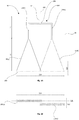
- FIG. 1A to 1D the example shown relates in general to a droplet deposition head 10 comprising one or more manifold components, for instance in the arrangement of Figures 1C and 1D , an upper manifold component 100 and a lower manifold component 50.
- the droplet deposition head 10 may comprise, at an end of one of the manifold components, two or more arrays 150 of fluid chambers together with corresponding actuating elements and nozzles for ejecting fluid in an ejection direction.
- the manifold components comprise one or more branched inlet paths 180 that branch into at least two corresponding sub-branches 182(a), 182(b) over a first portion of the height 11 of the droplet deposition head 10 in the ejection direction 505.
- the one or more branched inlet paths 180 are provided, for instance, within the upper manifold component 10.
- the manifold components also provide a plurality of widening chambers 55. Specifically, these are provided within the manifold components over a second portion of their height 12 in the ejection direction 505.
- the plurality of widening chambers 55 may, for instance, be provided within the lower manifold component 50.
- Each of the sub-branches 182(a),(b) may be fluidically coupled to a respective widening chamber 55.
- the branched paths and widening chambers not only allow fluid to be supplied to the droplet deposition head via using only a small number of inlet ports, and in some cases a single inlet port, but also allow fluid to be distributed, for example at a substantially even pressure and flow rate, to each of the fluid chambers of the array. This may simplify coupling of the droplet deposition head to a fluid supply. Providing such an arrangement of branched paths and widening chambers may enable the droplet deposition head to be relatively compact in the ejection direction, which may in turn simplify integration of the head (or, indeed, a number of like heads) into a larger droplet deposition apparatus.
- certain constructions having such branched paths and widening chambers may be compact in a direction perpendicular to the array direction. As noted above, this may assist in achieving a desired level of accuracy in droplet placement on the deposition medium, since maintaining the medium in a desired spatial relationship with respect to the arrays while the head(s) and the medium are moved relative to each other is typically more complex when the heads are relatively larger in the direction of movement (generally perpendicular to the array direction).
- the droplet deposition head 10 extends, in an ejection direction, from a first end, at which a fluid inlet 120 is located, to a second end, at which two arrays 150 of fluid chambers are located.
- the head 10 further includes a manifold component 80, with the two arrays 150 being mounted at an end of the manifold component 80.
- each of the fluid chambers in the two arrays 150 is provided with a respective actuating element and a respective nozzle.
- each array 150 extends in an array direction 500.
- the two arrays 150 shown in Figures 1A and 1B are spaced apart, one from the other, in a depth direction 510 (which, in the specific arrangement displayed, is substantially perpendicular to the array direction 500 and to the ejection direction 505), allowing the two arrays 150 to overlap in the array direction 500. It will be understood that the corresponding nozzles for the arrays will be similarly arranged.
- each array of fluid chambers is provided by a respective actuator component, which, in the case of a thin-film type droplet deposition head, may be a silicon die stack.
- a respective actuator component which, in the case of a thin-film type droplet deposition head, may be a silicon die stack.
- An example of such an actuator component is described further below with reference to Figure 13 .
- the amount of overlap in the array direction 500 is small in comparison to the length of each array 150 in the array direction 500.
- This overlap may allow the two arrays 150 to collectively address a deposition medium (such as a sheet of paper, ceramic tile, circuit board etc.) in a similar manner to a single array having the overall width of the two arrays, as it is indexed past the head 10, for instance in depth direction 510.
- the two arrays may, for example, enable the medium to be addressed in a single pass, where their overall width is sufficiently large.
- the overlap region may allow for fine alignment between the two arrays by electronic means, for example by selecting suitable nozzles between the arrays in the overlap region and controlling their droplet ejection properties through their individual drive waveform.
- the branched inlet path 180 is fluidically coupled to the fluid inlet 120 and is provided within the manifold component 80 over a first portion 11 of the height of the droplet deposition head 10 in the ejection direction 505.
- the branched inlet path 180 divides, at a branching point 186, into two sub-branches 182(a),(b).
- these sub-branches are end sub-branches 182(a),(b); the branched inlet path 180 culminates in these end sub-branches 182(a),(b).
- Each of the end sub-branches 182(a),(b) is fluidically coupled to the fluid inlet 120 via the main branch 181 of the branched inlet path 180.
- each widening inlet chamber 55(a), 55(b) in the array direction 500 increases with distance in the ejection direction 505 from its first end to its second end. In this way, the width of each widening inlet chamber 55 increases as it approaches the arrays 150.
- the width of the widening chamber in the array direction 500 increases at a substantially constant rate with increasing distance in the ejection direction 505.
- the sides of each widening inlet chamber 55 are substantially straight, when viewed in a depth direction 510 (substantially perpendicular to the array direction 500 and the ejection direction 505).
- the sides (with respect to the chamber height in the ejection direction 505) of the widening inlet chamber 55(a), 55(b) may be shaped in such a way as to assist in providing fluid to the chambers within the corresponding one of the arrays 150 with balanced flow characteristics (for instance with substantially balanced pressures, and/or with balanced flow rates and/or with balanced velocities).
- the sides of each widening inlet chamber 55 in some alternative constructions may instead be convex, or concave, when viewed in the depth direction 510 (though such shapes may, depending on the circumstances, be more difficult to manufacture).
- each widening inlet chamber 55 in the array direction 500 may increase with distance in the ejection direction 505 from its first end to its second end in any suitable manner.
- the increase may, for example, be gradual and/or the width in the array direction may increase substantially monotonically with respect to distance in the ejection direction 505, as is the case in Figure 1A .
- each widening inlet chamber 55 does not change significantly over the height of the widening inlet chamber 55; however, in other examples the depth may taper towards the second end of the widening inlet chamber 55, where it is fluidically connected to a corresponding one of the arrays 150.
- the size of the widening inlet chamber in the depth direction 510 may decrease with increasing distance in the ejection direction 505.
- the depth and width of the widening inlet chamber might, for example, change in such a way that the cross-sectional area of the widening inlet chamber remains constant for substantially the whole of its height.
- each widening inlet chamber 55 is fluidically connected, at its first end, to a corresponding one of the end sub-branches 182(a), 182(b) and, at its second end, to a corresponding one of the arrays 150.
- widening inlet chamber 55(a) is fluidically connected at its first end to sub-branch 182(a) and is fluidically connected at its second end to array 150(a), whereas widening inlet chamber 55(b) is fluidically connected at its first end to sub-branch 182(b) and is fluidically connected at its second end to array 150(b).
- each of the widening inlet chambers 55 at its second end is substantially equal to the width of the array 150 to which it supplies fluid. This may assist in evenly distributing fluid over the length of the array 150.
- each widening inlet chamber 55 in the ejection direction 505 is greater than its extent in the array direction 500. This may assist in developing an evenly distributed flow of fluid at the ends of the widening inlet chambers 55 that are connected to the arrays 150. More generally, a similar effect may be experienced where the extent of each widening inlet chamber 55 in the ejection direction 505 is approximately equal to or greater than its extent in the array direction 500.
- the branched inlet path 180 is fluidically connected so as to receive fluid from the fluid inlet 120, which is then conveyed through the branched inlet path 180, until it reaches the end sub-branches 182(a), 182(b).
- Each of the end sub-branches 182(a), 182(b) is then fluidically connected so as to supply fluid to a respective one of the widening inlet chambers 55 at a first end thereof (that furthest from the arrays 150).
- the second end (that nearmost the arrays 150) of each of said widening inlet chambers 55 is configured to supply fluid to a corresponding array 150.
- each sub-branch within the branched inlet path 180 is adapted to provide balancing of the flow characteristics for the fluid in the sub-branches, for instance so that the sub-branches have balanced pressures, and/or balanced flow rates and/or balanced velocities.
- the two widening inlet chambers 55(a), 55(b) have substantially the same shape.
- the widening inlet chambers 55 of the droplet deposition head 10 may be shaped so as to have substantially the same effect on fluid flowing through them.
- the fluid inlet 120 is configured to receive fluid from a fluid supply system, which may supply fluid at a positive pressure.
- the actuating elements of the arrays 150 are configured to be actuable by drive circuitry (not shown), such as ICs (Integrated Circuits) or ASICs (Application-Specific Integrated Circuits), to eject droplets from the nozzles of the chambers that are deposited on a deposition medium.
- fluid is supplied to the droplet deposition head 10 via the fluid inlet 120 and thereby reaches the branched inlet path 180.
- the fluid flows down along the branched inlet path 180 and splits from a main branch 181, at branching point 186, into each of two sub-branches 182(a), 182(b).
- these sub-branches are end sub-branches 182(a), 182(b).
- each end sub-branch 182(a), 182(b) From each end sub-branch 182(a), 182(b), the fluid flows into a first end of a corresponding widening inlet chamber 55(a), 55(b).
- Each widening inlet chamber 55(a), 55(b) widens as the fluid flows down, in an ejection direction 505, through the droplet deposition head 10 towards the arrays 150. Because each widening inlet chamber 55 widens, the fluid is spread out and distributed over the length of each array 150 at the second end of each widening inlet chamber 55.
- each widening inlet chamber 55 may be shaped such that fluid is distributed to the chambers within the corresponding one of the arrays 150 with balanced flow characteristics (for example, with balanced pressures, and/or with balanced flow rates and/or with balanced velocities for the chambers of the arrays).
- the combination of the branched inlet path 180 and widening inlet chambers 55 may supply fluid from a single fluid inlet port 120 to the chambers of a number of arrays 150 with balanced flow characteristics.
- the droplet deposition head 10 comprises an upper manifold component 100 and a lower manifold component 50.
- the lower manifold component 50 is coupled to the upper manifold component 10.
- the upper manifold component 100 comprises the branched inlet path 180, including the main branch 181, the branching point 186 and the end-sub branches 182(a), 182(b).
- the lower manifold component 50 comprises the widening inlet chambers 55.
- the upper manifold component 100 may be coupled to the lower manifold component 50 in any suitable manner such as, for example, using adhesive or fixing means, such as a screw or bolt, or via an ultrasonic weld.
- the droplet deposition head 10 may be formed, at least in part, from a plurality of layers 600.
- each of the layers extends in a plane that is generally normal to the ejection direction 505.
- the branched inlet paths 180 and the widening inlet chambers 55 are formed by the different layers 600 being stacked upon each other.
- the upper manifold component 100 While in the specific example shown in Figures 1C the upper manifold component 100 is illustrated as being attached directly to the lower manifold component 50, the upper manifold component 100 could, for example, be connected to the lower manifold component 50 with a plurality of flexible connectors, each of which providing a fluid path therethrough. An example of such a connection arrangement will be described in more detail below with reference to Figure 4 .
- Such flexible connectors may reduce the transfer of mechanical stress from the upper manifold 100 to the lower manifold 50. This may be an important consideration, for instance, when a user is connecting the inlet port 120 to a fluid supply or reservoir.
- a driver IC may be provided on the outer surface of the droplet deposition head 10.
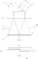
- branched inlet path 180 includes only one branching point 186 and, therefore, only two sub-branches 182(a), 182(b), it should be appreciated that branched inlet paths 180 could split into more sub-branches 182(a),(b). This will be demonstrated with reference to the example droplet deposition head 10 shown in Figures 2A and 2B , which is in many respects similar to the droplet deposition head 10 shown in Figures 1A and 1B .
- the branched inlet path 180 in the upper manifold 100 splits from a main branch 181 and culminates in four end sub-branches 182(a)-(d), with each end sub-branch 182(a)-(d)being fluidically coupled to a respective widening inlet chamber 55.
- main branch 181 branches at a first-level branching point 186(i) (where the suffix (i) indicates the first level) into two sub-branches, which in turn branch at respective branching points 186(ii)(a), 186(ii)(b) (where the suffix (ii) indicates the second level) into the four end sub-branches 182(a)-(d).
- the branched inlet path 180 includes only three branching points 186(i), 186(ii)(a), 186(ii)(b), in other examples, each branched inlet path 180, by having the appropriate number of branching points 186 (and/or by branching into more than two sub-branches 182 at each branching point 186), may culminate in any other number of end sub-branches 182.
- the droplet deposition head 10 shown in Figures 1A-1D and 2A-2B only a single fluid inlet 120 is provided.
- a single type of fluid e.g. one colour of ink, in the case where the droplet deposition head 10 is configured as an inkjet printhead
- the droplet deposition head 10 could include a first group of two or more arrays 150 for depositing a first type of droplet fluid and a second group of arrays 150 for depositing a second type of droplet fluid.
- the different types of droplet fluid may, where the droplet deposition head 10 is configured as an inkjet printhead, correspond to different colours of ink, for instance.
- more than two such groups may be provided; for example, four groups of arrays could be provided, one for each of the four process colours (cyan, magenta, yellow and black).
- the fluid paths may be arranged such that the different types of fluid are separated from each other within the head.
- each type of droplet fluid may be received from a respective fluid inlet 120.
- adjacent arrays 150 within the same group may be spaced apart in a depth direction 510 so as to allow them to overlap in the array direction 500, for example by a relatively small amount in comparison with the length of the array.
- each of the arrays 150 in a first group may be aligned in the array direction 500 with a respective one of the arrays 150 in a second group. Examples of such an arrangement will be described further below with reference to Figures 6B and 11 ; the examples shown in Figures 1A-1F and 2A-B include only one group of arrays. In this way, as the deposition medium is indexed past the droplet deposition heads, each portion of the width (in the array direction 500) of the deposition medium is addressed by an array from every group.
- pairs of arrays 150 from the same group may be provided side-by-side, with both of the arrays within the pair being fluidically connected to the same widening inlet chamber 55.
- the arrays 150 within each such pair of arrays may be disposed on either side of the shared widening inlet 55.
- the widening inlet 55 may thus appear to divide or separate the arrays 150 when viewed from the ejection direction 505 (though it should be noted that it may not necessarily physically separate the pair of arrays 150, especially where the pair of arrays 150 is provided by a single actuator component, and may thus be offset from the pair of arrays in the ejection direction 505).
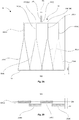
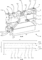
- Figures 3A, 3B and 3C show, respectively, a cross-sectional view, a side view and an end view of a droplet deposition head 10 according to another example (with the cross-section of Figure 3A being taken in the plane indicated by dashed line 3A in Figures 3B and 3C ).
- the droplet deposition head 10 of Figures 3A-3C comprises an upper manifold component 100 and a plurality of lower manifold components 50, in this example two lower manifold components 50.
- the manifold components provide a fluid outlet 220, in addition to a fluid inlet 120.
- the droplet deposition head 10 of Figures 3A, 3B and 3C may be considered an example of a head where the plurality of manifold components 100, 50 provides one or more fluid outlets.
- the example droplet deposition head 10 shown in Figures 3A, 3B and 3C has a similar branched fluid inlet path structure 180 to that described above in relation to Figures 1A, 1B , 2A and 2B , but additionally has a branched fluid outlet path structure 280 for returning fluid to the fluid supply system.
- This may enable recirculation of fluid through the head, for example by establishing a continuous flow of fluid through the head during use. More particularly, there may be established a continuous flow of fluid through each of the chambers in the arrays. This flow may, depending on the configuration of the fluid supply system (e.g. the fluid pressures applied at the fluid inlet 120 and fluid outlet 220), continue even during droplet ejection, albeit potentially at a lower flow rate.
- the fluid outlet 220 is located at the same end of the droplet deposition head 10 as the fluid inlet 120 (specifically, the end furthest from the arrays 150 in the droplet ejection direction 505).
- two branched outlet end sub-branches 282(a), 282(b) are provided within the upper manifold component 10.
- Each of the branched outlet end sub-branches 282(a), 282(b) is fluidically connected, at a branching point 286, to the main branch 281 of the branched outlet path 280.
- the main branch 281 is, in turn, coupled to the fluid outlet 220.
- the plurality of sub-branches 282(a), 282(b) and the main branch 281 together form a single branched outlet path 280.
- the branched outlet path 280 may nonetheless be described, in a topological sense, as "culminating" in the end sub-branches 282(a), 282(b).
- each narrowing outlet chamber 60(a), 60(b) in the array direction decreases with distance in a direction opposition to the ejection direction 505 from a first end (that nearmost the arrays 150), which is fluidically coupled to a corresponding fluid array 150, to a second end (that furthest from the arrays 150), which is fluidically coupled to a corresponding one of the end sub-branches 282(a), 282(b) provided by the branched outlet path 280.
- the width in the array direction 500 of each of the narrowing outlet chambers 60 at its first end is substantially equal to the width of the array 150 from which it receives fluid. As noted above, this may assist in evenly distributing fluid over the length of each array 150.
- each widening inlet chamber 55 in the ejection direction 505 is greater than its extent in the array direction 500. As also discussed above, this may assist in developing an evenly distributed flow of fluid at the ends of the widening inlet chambers 55 that are connected to the arrays 150.
- the fluid inlet structure overlaps parts of the fluid outlet structure in the array direction 500.
- each narrowing outlet chamber 60 overlaps, in an array direction 500 of the droplet deposition head 10, with a widening inlet chamber 55.
- the branched inlet path 180 overlaps, in the array direction 500, with the branched outlet path 280.
- the branched outlet path 180 overlaps with the branched inlet path 280 in the head depth direction 510 as well (the depth direction 510 being perpendicular to the array direction 500 and to the ejection direction 505).
- Each lower manifold component 50 provides fluidic connection to at least one array of chambers 150.
- each lower manifold component 50 has mounted thereupon a respective array of chambers 150.
- one lower manifold component 50(a) is spaced apart from the other 50(b) in the depth direction 510, while overlapping in the array direction 500.
- the array 150(a) of one lower manifold component is spaced apart from the array 150(b) of the other lower manifold component 50(b) in the depth direction 510, while the arrays 150(a), 150(b) overlap in the array direction 500.
- the corresponding nozzles for the arrays will be similarly arranged.
- the fluid inlet structure shown in Figures 3A, 3B and 3C (which includes branched inlet path 180 and widening inlet chambers 55(a), 55(b)) connects to a fluid supply system using inlet 120 and thereafter functions in generally the same way as that described above in reference to Figures 1A, 1B , 2A and 2B .
- the fluid outlet 220 is connectable to a fluid supply system so that the head 10 can return droplet fluid to the fluid supply system.
- the fluid supply system may, for example, be configured to apply a negative pressure to the fluid outlet 220 so as to draw droplet fluid through the system.
- the fluid supply system will typically be configured to apply a positive pressure to the fluid inlet 120 (though, potentially, the negative pressure at the fluid outlet 220 could be used alone in some circumstances).
- each of the branched outlet end sub-branches 282(a), 282(b) is configured to receive fluid from a corresponding narrowing outlet chamber 60(a), 60(b).
- the first end of each of the narrowing outlet chambers 60(a), 60(b) (that nearmost the arrays 150) is configured to receive fluid from a respective array 150.
- the width of the widening inlet chambers 55 in the array direction 500 increases at a substantially constant rate with increasing distance in the ejection direction 505.
- the sides of each widening inlet chamber 55 are substantially straight, or linear, when viewed in depth direction 510 (which is substantially perpendicular to the array direction 500 and the ejection direction).
- the sides (with respect to the chamber height in the ejection direction 505) of the widening inlet chamber 55(a), 55(b) may be shaped in such a way as to assist in providing fluid to the chambers within the corresponding one of the arrays 150 with balanced flow characteristics (for instance with substantially balanced pressures, and/or with balanced flow rates and/or with balanced velocities).
- the sides of each widening inlet chamber 55 in some alternative constructions may instead be convex, or concave, when viewed in the depth direction 510 (though such shapes may, depending on the circumstances, be more difficult to manufacture).
- each widening inlet chamber 55 in the array direction 500 may increase with distance in the ejection direction 505 from its first end to its second end in any suitable manner.
- the increase may, for example, be gradual and/or the width in the array direction may increase substantially monotonically with respect to distance in the ejection direction 505, as is the case in Figure 3A .
- the width, in the array direction 500, of the narrowing outlet chambers 60 decreases at a substantially constant rate with increasing distance in a direction opposition to the ejection direction 505.
- the sides of each narrowing outlet chamber 60 are substantially straight, or linear, when viewed in depth direction 510 (which is substantially perpendicular to the array direction 500 and the ejection direction).
- each narrowing outlet chamber 60(a), 60(b) may be shaped so as to assist in balancing the flow characteristics of fluid at the arrays 150.
- the shape may assist in balancing the pressures and/or flow rates and/or velocities of the fluid in the chambers of the arrays 150.
- the sides of each narrowing outlet chamber 60 in some alternative constructions might instead be convex, or concave, when viewed in the depth direction 510 (though such shapes may, depending on the circumstances, be more difficult to manufacture).
- each narrowing outlet chamber 60(a), 60(b) may decrease with distance in a direction opposition to the ejection direction 505 in any suitable manner.
- the increase may, for example, be gradual and/or the width in the array direction may increase substantially monotonically with respect to distance in the ejection direction 505, as is the case in Figure 3A .
- each widening inlet chamber 55 does not change significantly with distance 55 in the ejection direction 505.
- the depth of each widening inlet chamber 55 may taper towards the second end of the widening inlet chamber 55, where it is fluidically connected to a corresponding one of the arrays 150.
- the size of the widening inlet chamber in the depth direction 510 may decrease with increasing distance in the ejection direction 505.
- the depth and width of the widening inlet chamber might, for example, change in such a way that the cross-sectional area of the widening inlet chamber 55 remains constant for substantially the whole of its height in the ejection direction 505.
- each narrowing outlet chamber 60 does not change significantly with distance 55 in the ejection direction 505.
- the depth of each narrowing outlet chamber 60 may taper towards the first end of the narrowing outlet chamber 60, where it is fluidically connected to a corresponding one of the arrays 150.
- the size of the narrowing outlet chamber 60 in the depth direction 510 may decrease with increasing distance in the ejection direction 505.
- the depth and width of the widening inlet chamber might, for example, change in such a way that the cross-sectional area of the narrowing outlet chamber 60 remains constant for substantially the whole of its height in the ejection direction 505.
- fluid is supplied to each array 150 of the droplet deposition head 10 in generally the same way as described above in relation to Figures 1A, 1B , 2A and 2B .
- the fluid may, as part of the recirculation of fluid through the head mentioned above, flow through each of the chambers.
- the fluid may flow along their lengths.
- the actuating elements of the array 150 are then actuated so as to cause the ejection of droplets through the nozzles of the chambers, some fluid will leave the chambers in the form of droplets.
- fluid that is not ejected will flow from the chambers into a corresponding narrowing fluid outlet chamber 60(a), 60(b) in the lower manifold 50.
- the flow is concentrated in a manner similar to a funnel so that the fluid flows out of the narrowing outlet chamber 60 and into an outlet end sub-branch 282(a), 282(b).
- Fluid flows through the outlet sub-branches 282(a), 282(b) of the branched outlet path 280 in the upper manifold 100 and is combined at a branching point 286, before flowing into and along the main path 281 of the branched outlet path 280.
- the fluid flows from the main branch 281 of the branched outlet path 280 to the fluid outlet 220, where it may return to the fluid supply system.
- droplet deposition head 10 of Figures 3A-3C has been described as having only one fluid inlet 120 and one fluid outlet 220, it should be appreciated that, particularly where different groups of arrays are provided, several fluid inlets and several fluid outlets could be included. For instance, a respective fluid inlet and a respective fluid outlet could be provided for each of a number of different types of droplet fluid. A respective group of arrays could be provided for each type of droplet fluid.
- the different types of droplet fluid may, where the droplet deposition head 10 is configured as an inkjet printhead, correspond to different colours of ink, for instance. Where the head is configured for use with several different types of droplet fluid, the fluid paths may be arranged such that the different types of fluid are separated from each other within the head.
- each lower manifold component 50 may provide fluidic connection to multiple arrays.
- a widening inlet chamber 55 may be configured to provide fluid to two arrays 150 from the same group.
- the two arrays may share a widening inlet chamber 55 but have a respective narrowing outlet chamber 60, such that there are two narrowing outlet chambers 60 and one widening inlet chamber 55 per two arrays 150 of the same group. Examples of such an arrangement will be described further below with reference to Figures 6B and 11 ; the examples shown in Figures 1A-1F and 2A-B include only one group of arrays.
- the two arrays 150 could each be provided with a respective widening inlet chamber 55 and share a single narrowing outlet chamber 60.
- each lower manifold component 50 may provide fluidic connection to arrays from two or more groups of arrays, with each group corresponding to a specific type of droplet fluid, as discussed above.
- arrays 150 that correspond to the same lower manifold component 50 and to the same group may be spaced apart from one another in the depth direction 510 and offset from one another in the array direction 500, for example by a small amount, for example, of the order of the nozzle spacing for each array.
- the offset could, for example be approximately 1/N times the nozzle spacing, where N is the number of arrays within the same group that correspond to the same lower manifold component (or, potentially, M+1/N times the nozzle spacing, where M is an integer).
- the nozzles of the N arrays may together provide an array of nozzles with spacing 1/N, when viewed in a depth direction 505, perpendicular to the array direction 500 and the ejection direction 510.
- the nozzles from the N arrays may accordingly be interleaved with respect to the array direction 500, for example as shown in Figure 6B , which shows an example where 2 arrays from a first group are interleaved and 2 arrays from a second group are interleaved.
- the multiple arrays may provide the printhead with a higher resolution than a single array.
- arrays 150 may overlap in the array direction 500 by an amount less than the distance between pressure chambers, such that their nozzles are interleaved with respect to the array direction 500. Such an arrangement may improve the resolution that can be printed by the droplet deposition head 10.
- each lower manifold component may provide fluidic connection to arrays from multiple groups.
- the arrays 150 corresponding to different groups may be aligned in the array direction 500. In this way, as the deposition medium is indexed past the droplet deposition heads, each portion of its width in the array direction 500 is addressed by an array from each of the two or more groups
- At least one of the narrowing outlet chambers 60 for each lower manifold component 50 may be provided adjacent an outer surface of that lower manifold component 50. Such an arrangement may provide cooling to circuitry coupled to the outer surface of the lower manifold component 50 or the droplet deposition head 10 more generally.
- the droplet deposition head shown in Figures 3A, 3B and 3C may comprise any of the features described above in relation to Figures 1A, 1B , 2A and 2B .
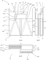
- Figures 4 to 12B illustrate a droplet deposition head 10 according to a further example.
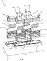
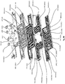
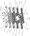
- Figure 4 shows an exploded perspective view of an example droplet deposition head 10.
- the droplet deposition head 10 comprises an upper manifold component 100 and four lower manifold components 50.
- the droplet deposition head of Figures 4 to 12B is configured for use with two different types of droplet fluid and, when connected to a suitable fluid supply system, may provide for recirculation of the droplet fluid, in a similar manner to that described above with reference to Figure 3A-3C . Accordingly, the droplet deposition head includes two fluid inlets 120(1), 120(2) and two fluid outlets 220(1), 220(2) (where the suffixes (1) and (2) indicate that the inlet/outlet is configured for use with, respectively, droplet fluid of the first and of the second type).
- a series of flexible connectors 75 between the upper manifold component 100 and each lower manifold component 50 are a series of flexible connectors 75. Some of the flexible connectors 75 couple end sub-branches 20 of the branched inlet paths 180 within the upper manifold component 100 to widening inlet chambers 50 within the lower manifold components 50, whereas other flexible connectors 75 couple end sub-branches 32 of the branched outlet paths 280 within the upper manifold component 100 to narrowing outlet chambers 55 within the lower manifold components 50.
- the flexible connectors 75 are therefore adapted to transfer fluid from the upper manifold component 100 to the lower manifold components 50, and vice versa.
- the flexible connectors may be individually designed so as to make respective small adjustments to individual fluid paths between the lower manifold components 50 and the upper manifold component 100. For instance, these adjustments may improve the balance of the flow characteristics of the paths (e.g. balancing the pressures, and/or the flow rates and/or the velocities, within the paths).
- the flexible connectors might be used to correct small deviations in flow characteristics that arise from manufacturing variability.
- the particular flexible connectors 75 in the example shown have an hourglass configuration, so that they narrow at their waists.
- the narrowing at the waist of each flexible connector 75 may allow it to bend or flex about the waist. This flexibility may assist in compensating for minor misalignments of the upper manifold component 100 with respect to the various lower manifold components 50.
- the flexible connectors 75 are adapted to flex and bend if one component, for instance the upper manifold component 10, is moved with respect to the other, for instance the lower manifold component 50, but to still maintain a sealed fluidic connection between the two. In this way, the flexible connectors 75 may reduce the transfer of mechanical stress from the upper manifold component to the lower manifold components while still acting to transfer fluid from the upper manifold component 100 to the lower manifold components 50, and vice versa.
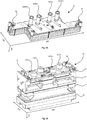
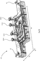
- FIG. 5A which shows a perspective view of an upper manifold component 100 of the droplet deposition head of Figure 4
- the specific example of an upper manifold component 100 shown is generally z-shaped, when viewed in the ejection direction 505.
- the z-shape of the upper manifold component 100 is configured to engage with a z-shape of another upper manifold component 100 so that a series of droplet deposition heads 10 can be arranged together on a support (such as a print bar, in the case of an inkjet printhead) in an interlocking, or tessellating manner so as to provide overlap between arrays from different heads.
- a support such as a print bar, in the case of an inkjet printhead
- the head could have a simple cuboid form.
- each inlet port 120(1), 120(2), and each outlet port 220(1), 220(2) may, for example, be configured to supply or receive a different type of fluid, such as a different colour of ink (the suffixes (1) and (2) indicate that the inlet or outlet port in question is configured for use with, respectively, a first or a second type of fluid).
- inlet port 120(1) and outlet port 220(1) are configured for, respectively, the supply and return of a first type of droplet fluid
- inlet port 120(2) and outlet port 220(2) are configured for, respectively, the supply and return of a second type of droplet fluid.
- the upper manifold component 100 is formed from a plurality of layers. As is shown in Figure 5A , the upper manifold component 100 comprises a fastening feature 30 at each end for coupling the upper manifold component 100 to a structure, such as a cover component (not shown).
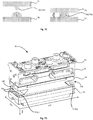
- lower manifold components 50 are each mounted in a respective recess in a base 200.
- the base 200 generally mirrors the shape of the upper manifold component 10.
- the frame 200 is adapted to receive the lower manifold components 50. More particularly, a carrier layer 76 of each lower manifold component is shaped so as to slot into the corresponding recess in base 200.
- the base 200 may have features to assist in mounting it on a support. For instance, it may include alignment features, such as one or more datums, as well as attachment features, such as screw-holes to allow the base 200 to be attached to the support using screws.
- each lower manifold component 50 comprises two inlet ports 65(1), 65(2) and two outlet ports 67(1), 67(2).
- each inlet port 65(1), 65(2), and each outlet port 67(1), 67(2) is configured to receive a different type of fluid, such as a different colour of ink.
- Each lower manifold component 50 supplies fluid to and receives fluid from a number of arrays of fluid chambers 150. More particularly, each lower manifold component 50 supplies fluid of a first type to, and receives fluid of a first type from, two arrays of fluid chambers 150, while also supplying fluid of a second type to, and receiving fluid of a second type from, two arrays of fluid chambers 150.
- each lower manifold component 50 is formed from a plurality of layers. Each layer extends generally perpendicularly to the ejection direction 505. As may also be seen, each widening inlet chamber 55 and each narrowing outlet chamber 60 is formed within several of the layers. Utilizing layers that extend generally perpendicularly to the ejection direction 505 may enable the various narrowing and widening chambers 55, 60 to be formed accurately and relatively straightforwardly, since the layers will generally "cut across" these chambers. Hence, only a small number of layers may be required, it being appreciated that the lower the number of layers, the better the alignment will be between the layers.
- the alignment between the top layer 70 in Figure 5B , which provides fluidic connection to the upper manifold component 100, and the bottom layer 76 in Figure 5B , which provides fluidic connection to the arrays 150 may be improved owing to reduced accumulation of alignment error.
- the lower manifold component 50 may be formed in any suitable manner; for example, it could be formed (at least in part) from a plurality of layers that each extend perpendicularly to the depth direction 505 or, potentially, layers that each extend perpendicularly to the array direction 500.
- each lower manifold component has four layers: a first lower manifold layer 70, a second lower manifold layer 72, a third lower manifold layer 74 and a fourth lower manifold layer 76, which is a carrier layer 76.
- the first lower manifold layer 70 is mounted within the second lower manifold layer 72, with the second lower manifold layer 72 having two arms 721 (a), 721 (b) that cradle the first lower manifold layer 70.
- Each lower manifold component 50 also comprises holes 52 that extend through the layers of the lower manifold component 50 at opposing ends. Each hole can receive a fastening means such as a screw, bolt, fastening rod etc. that fastens the layers together.
- a fastening means such as a screw, bolt, fastening rod etc. that fastens the layers together.
- the layers of the lower manifold component may be coupled by glue bonding, welding, etc.
- Figure 6A which is a cross-sectional view of the lower manifold component shown in Figures 4 and 5B , illustrates the internal features of the lower manifold component. More particularly, Figure 6A illustrates as solid objects the respective spaces within the widening inlet chamber 55(1), the narrowing outlet chambers 60(1)(i), 60(1)(ii) and the inlet and outlet port 65(1), 67(1) for one type of droplet fluid.
- the first lower manifold layer 70 comprises inlet ports 65(1), 65(2) and outlet ports 67(1), 67(2).
- the inlet ports 65(1), 65(2) are located towards the centre of the first layer 70 of the lower manifold component 50 (which is uppermost in Figure 6A ), and the outlet ports 67(1), 67(2) are located towards the sides of the first layer 70 of the lower manifold component 50.
- the inlet ports 65(1), 65(2) are located relatively more centrally (when viewed from the array direction 500) than the outlet ports 67(1), 67(2).
- the ports 65, 67 are integrally moulded as part of the first lower manifold layer 70.
- the first lower manifold layer 70 also comprises corresponding inlet and outlet ducts 68, 69 for the inlet and outlet ports 65, 67 respectively.
- Each inlet duct is configured to supply fluid to a single corresponding widening inlet chamber 55
- each outlet duct 69 is configured to receive fluid from two corresponding narrowing outlet chambers 60.
- duct 68(1) supplies fluid to widening inlet chamber 55(1)
- duct 69(1) receives fluid from both narrowing outlet chamber 60(1)(i) and narrowing outlet chamber 60(1)(ii).
- each lower manifold chamber such as the widening inlet chamber 55 or the narrowing outlet chamber 60, may provide fluidic connection to at least two arrays 150 from the same group.
- each widening outlet chamber 55(1), 55(2) is fluidically connected to two arrays 150; thus, a pair of arrays 150 shares the same widening inlet chamber 55(1), 55(2).
- a pair of arrays 150 could instead (or possibly in addition) share the same narrowing outlet chamber 60.
- the lower manifold component 50 is configured for use with two types of fluid, with each type of fluid being supplied to the lower manifold component 50 via a respective inlet port 65(1), 65(2) and being returned to the upper manifold component 100 via a respect outlet port 67(1), 67(2).
- Each widening inlet chamber 55 is configured to distribute a specific type of fluid from a respective inlet port 65(1), 65(2) to two arrays 150 from the same group.
- the two arrays 150 in the same group receive fluid from the same widening inlet chamber 55.
- Figure 6B is a schematic end view of the lower manifold component 50 of Figure 6A , taken from the end at which the arrays are located.
- nozzle rows 155(1)(i)-(ii) and 155(2)(i)-(ii) are provided adjacent the carrier layer 76 of the lower manifold component 50, each nozzle row 155 corresponding to a respective array 150.
- the nozzle rows 155 within a pair are located adjacent one another, as are the corresponding arrays of fluid chambers.
- Each pair of arrays may, for example, be provided by a single actuator component, though in other constructions each array could be provided by a separate actuator component, or all of the arrays for a lower manifold component could be provided by the same actuator component.
- the first pair of nozzle rows 155(1)(i)-(ii) is configured for ejection of one type of droplet fluid and the second pair of nozzle rows 155(2)(i)-(ii) is configured for ejection of another type of droplet fluid.
- widening inlet chamber 55(1) is fluidically connected to the array corresponding to nozzle rows 155(1)(i), 155(1)(ii), whereas widening inlet chamber 55(2) is fluidically connected to nozzle rows 155(2)(i), 155(2)(ii).
- narrowing outlet chambers 60(1)(i) and 60(1)(ii) are fluidically connected to the array corresponding to nozzle rows 155(1)(i) and 155(1)(ii) respectively
- narrowing outlet chambers 60(2)(i) and 60(2)(ii) are fluidically connected to the array corresponding to nozzle rows 155(2)(i) and 155(2)(ii) respectively.
- the two arrays 150 within a group are disposed on either side of the corresponding shared widening inlet chamber 55.
- the widening inlet chamber 55 may thus appear to divide or separate the arrays 150 when viewed from the ejection direction 505.
- each narrowing outlet chamber 60 is configured to receive fluid from only a single array 150 and return it to an outlet port 67(1), 67(2).
- the two narrowing outlet chambers 60 corresponding to one type of fluid return fluid to the same outlet port 67(1), 67(2), such that they share the outlet port 67(1), 67(2).
- nozzles 155(1)(i), which correspond to an array within the first group are aligned with nozzles 155(2)(i), which correspond to an array within the second group.
- nozzles, 155(1)(ii) are aligned with nozzles 155(2)(ii).
- Figure 6B may be considered an example of where, for arrays corresponding to a particular one of the lower manifold components 50, each array 150 in a first group is aligned in the array direction 500 with a respective array 150 in the second group. In this way, as the deposition medium is indexed past the droplet deposition head 10, each portion of its width in the array direction 500 is addressed by an array 150 from every group within the lower manifold component 50.
- the nozzle rows 155 for arrays 150 within the same group are offset from each other in the array direction 500 by a small amount 502. It will be appreciated that the respective arrays of chambers 150 will be offset in substantially the same manner.
- arrays 150 corresponding to the same group and the same lower manifold component 50 may be offset in the array direction 500 with respect to one another.
- This offset may, for example, be of the order of the nozzle spacing 501 for each array.
- the nozzles of the N arrays may together provide an array of nozzles with spacing 1/N, when viewed in a depth direction 505, perpendicular to the array direction 500 and the ejection direction 510.
- the nozzles 155 from the N arrays may accordingly be interleaved with respect to the array direction 500, as shown in Figure 6B .
- the multiple arrays may provide the printhead with a higher resolution than a single array.
- each outlet duct 69 for coupling two narrowing outlet chambers 60 to the corresponding one of the outlet ports 67(1), 67(2) combines the two narrowing outlet chambers 60 fluidically in the upper layer 70 of the lower manifold 50.
- two narrowing outlet chambers 60(1)(i), 60(1)(ii) may be merged by forming a merging portion between the two parallel upper slots of the two narrowing outlet chambers 60(1)(i), 60(1)(ii) to form a 'U'- shaped fluid path in the plane of layer 70.
- each parallel channel of each outlet duct 69 couples to a corresponding narrowing outlet chamber 60, such that each outlet duct 69 fluidically couples to two narrowing outlet chambers 60.
- the substantially parallel channels of the outlet ducts 69 are configured to extend along either side, with respect to the depth direction 510, of a channel of the inlet duct 68 which couples one of the widening inlet chambers 55 to a corresponding one of the inlet ports 65(1), 65(2).
- FIG. 6A and 6B While the specific example shown in Figures 6A and 6B includes a widening inlet chamber 55 that is shared between two arrays within the same group, in other examples one (or more) of the narrowing outlet chambers 60 might be shared between two arrays within the same group in a similar manner. Hence, or otherwise, there may be provided a respective widening inlet chamber 55 for each array (whether within the same group or otherwise). In other examples, each array may be provided with a respective widening inlet chamber 55 and a respective narrowing outlet chamber 60. Thus, there may be one widening inlet chamber 55 for each narrowing outlet chamber 60.
- this layer is fluidically coupled to the first lower manifold layer 70 and comprises a first portion of the widening inlet chambers 55 and the narrowing outlet chambers 60, where, with increasing distance in the ejection direction 505, each of these chambers widens in the array direction 500 (it being noted that the width of the narrowing outlet chambers 60 narrows with increasing distance in the opposite direction to the ejection direction 505).
- the widening inlet chambers 55 and the narrowing outlet chambers 60 are substantially aligned with respect to the array direction 500 (though they may be offset with respect to each other by a small amount, e.g. a fraction of the nozzle spacing 501, in the same way as their corresponding arrays of fluid chambers 150).
- this layer is fluidically coupled to the second lower manifold layer 72 and comprises a second portion of the widening inlet chambers 55 and the narrowing outlet chambers 60, where, with increasing distance in the ejection direction 505, each of these chambers continues to widen in the array direction 500.
- the carrier comprises an end portion of the widening inlet chambers 55 and of the narrowing outlet chambers 60, where these chambers remain substantially of constant width in the array direction 500.
- the end portions of the narrowing outlet chambers 60 and the widening inlet chambers 55 do not narrow or widen; they have sides that generally extend parallel to the ejection direction 505. This constant width portion may allow further flow development to a substantially uniform velocity profile across the array of fluid chambers 150.
- each actuating element such as a piezoelectric actuator, and a respective nozzle
- Each actuating element is actuable to eject a droplet of fluid in an ejection direction 505 through a corresponding nozzle.
- Each array extends in an array direction 500, similar to that shown in Figures 1B , 2B and 3C .
- the width, in the array direction 500, of the end portion (the "straight" portion) of the narrowing outlet chambers 60 and the widening inlet chambers 55 is substantially the same as that of the arrays 150. This width may also correspond to the width of the widening inlet chambers 55 and narrowing outlet chambers 60 of the third lower manifold layer 74 at its widest point at the bottom (i.e. nearmost the arrays 150) of the third lower manifold layer 74.
- the first, second and third lower manifold layers 70, 72, 74 may, for example, be formed of polymeric materials and/or plastic materials. Factors that may be taken into account when selecting appropriate polymeric materials and/or plastic materials are discussed in further detail below.
- a filled polymeric material may be appropriate; the filler may suitably be a fibrous material, such as glass, mineral and/or ceramic fibres. Filling may impart greater mechanical strength and thermal resistance. Moreover, it may aid in achieving a particular coefficient of thermal expansion (CTE) for the layers.
- CTE coefficient of thermal expansion
- the carrier 76 may be made from a different material to the other layers of the lower manifold.
- the carrier 76 may be made from a material whose coefficient of thermal expansion is similar to, or matches with, that of the actuator components that are mounted thereupon. Such thermal matching may reduce the amount of mechanical stress that the actuator component experiences during use.
- the carrier 76 may be made from a material that is thermally conductive, for instance more thermally conductive than the other layers of the lower manifold component. This may assist in transferring heat away from the actuator component(s) that are mounted on the carrier 76. For instance, heat may be transferred to fluid within the narrowing outlet chambers 60, with the thus-heated fluid then flowing out of the lower manifold component 50 and therefore drawing heat out away from the actuator component(s). In constructions, such as that shown in Figure 6A , where the carrier layer 76 includes a "straight" portion of the narrowing outlet chambers 60, this heat transfer may be particularly efficient since it can occur over a large surface area.
- the carrier 76 may usefully function as a heat sink, drawing heat away from the actuator and transferring it to the environment.
- a driver IC is provided on the outer surface of the lower manifold component
- thermal conductivity may assist in transferring heat away from such a driver IC.
- heat from the driver IC may, for instance, be transferred to fluid within the narrowing outlet chambers 60, with the thus-heated fluid then flowing out of the lower manifold component 50 and therefore drawing heat out away from the driver IC.
- the narrowing outlet chambers 60 for the lower manifold component 50 is provided adjacent an outer surface of that lower manifold component 50 and the driver IC is mounted on that surface, this type of heat transfer may be particularly efficient.
- the carrier 76 may function as a heat sink and may thus draw heat away from the driver IC and transfer it to the environment, even where no outlet path is provided.
- the carrier layer 76 may be made of ceramic material(s). This may be particularly appropriate as many actuator components will themselves be made of ceramic materials. Hence, it may be easier to match the coefficients of thermal expansion of the carrier and of the actuator component. In addition, ceramic materials may provide good thermal conductivity.
- the carrier layer might be formed of a metal or an alloy. Where an alloy is used, the formulation may be tailored to provide desired properties, such as a desired CTE and/or thermal conductivity.
- a filled polymeric material may be utilised for the first, second and third lower manifold layers 70, 72, 74.
- Such filling may, for example, assist in reducing the difference in CTE between the first, second and third lower manifold layers 70, 72, 74 and the carrier layer 76.
- Figures 7A-7C illustrate certain features of the lower manifold component 50 that may address issues that arise with layers having different CTE values.
- Figure 7A which is a perspective view from below of the first, second and third layers 70, 72, 74 of the lower manifold component shown in Figures 4 , 5B , 6A and 6B , the side of the third layer 74 to which the carrier layer 76 is bonded is clearly visible. As is apparent from the drawing, this side extends generally perpendicular to the ejection direction 505.
- Figure 7B which is a perspective view of the carrier layer 76, shows clearly the side of the carrier layer 76 to which the third layer 74 is bonded. This similarly extends generally perpendicular to the ejection direction 505.
- each ridge 741/742 may be pressed into a corresponding portion of the adhesive pattern 2, as is shown in Figure 7C . As shown in the drawing, this may, for example, lead to the ridge 741/742 splitting the corresponding portion of adhesive 2 into two wedge-shaped portions, or fillets.
- substantially the only contact between the bonding sides is through the ridges 741, 742.
- the ridges may thus conveniently determine the separation distance d between the layers 74, 76, as indicated in Figure 7C .
- the assembly may then be necessary to cure the adhesive. In some cases, this may involve the assembly being heated to a relatively high temperature (in many cases more than 80°C). Such heating will cause the layers to expand, with the third layer 74 expanding by a different (typically greater) amount than the carrier layer 76. Had the bonding sides of the two layers 74, 76 simply been flat, this differential thermal expansion might have led to warpage and, potentially, the separation of the two layers as a result of the curing process.
- Such issues may, for example, arise because the typical thickness at which adhesive can be applied (which is determined by such factors as viscosity, surface energy, surface roughness etc.) is relatively small. A possible consequence is that the bonding sides are secured only a short distance apart. With such a thin layer of adhesive between the bonding sides, almost all of the expansion of the bonding side of one layer is applied to the bonding side of the other layer. This in turn may lead to the layers 74, 76 bending with a relatively tight radius of curvature, potentially leading to the separation of the layers. Such bending caused by the heating is effectively locked-in to the component by the curing of the adhesive. When the component returns to room temperature, stress/strain is generated within the component as the layers attempt to return to their original sizes. Still greater stresses may be experienced during shipping of the component, for example if the component is shipped by airfreight, where temperatures might fall to -20°C, for instance. Such stresses may, as mentioned above, lead to separation of the layers.
- the ridges 741, 742 essentially enable the adhesive to span a greater distance between the layers.
- less stress will be imparted to the adhesive when the component returns to room temperature.
- a possible consequence is that there is less risk of the adhesive failing and the layers thus separating.
- formed in the bonding side of the third layer 74 are respective apertures for each widening inlet chamber 55 and for each narrowing outlet chamber 60. Specifically, there are two apertures 745(1), 745(2) corresponding to respective widening inlet chambers 55(1), 55(2) and four apertures 746(1)(i), 746(1)(ii), 746(2)(i), 746(2)(ii) corresponding to respective narrowing outlet chambers 60(1)(i), 60(1)(ii), 60(2)(i), 60(2)(ii).
- respective apertures for each widening inlet chamber 55 and for each narrowing outlet chamber 60 are formed in the bonding side of the carrier layer 76. Specifically, there are two apertures 765(1), 765(2) corresponding to respective widening inlet chambers 55(1), 55(2) and four apertures 766(1)(i), 766(1)(ii), 766(2)(i), 766(2)(ii) corresponding to respective narrowing outlet chambers 60(1)(i), 60(1)(ii), 60(2)(i), 60(2)(ii).
- each of the apertures in the bonding side of the third layer 74 directly opposes a respective aperture in the bonding surface of the carrier layer 76.
- an additional aperture 747, 767 is formed in the bonding side of each of the third layer 74 and the carrier layer 76. These apertures may simplify the moulding of the layers and should be understood as being entirely optional.
- the ridges 741, 742 are formed on the bonding side of the third layer 74, they could of course be formed on the bonding side of the carrier layer 76 instead. Nonetheless, as the third layer 74 is formed of polymeric material, it may be particularly straightforward to form the ridges 741, 742 on the third layer 74.
- Figure 7D is a perspective view of the lower manifold component 50 of Figures 4 , 5B , 6A and 6B , still further features to address issues caused by stresses arising as a result of the curing process are visible.
- a recess 748 is formed at each end of the third layer 74 with respect to the array direction 500.
- Each of these recesses 748 separates one of the reduced-thickness regions 744(i), 744(ii) from another portion of the first layer with respect to the ejection direction 505, in this case a portion adjacent the next layer, second layer 72.
- a second group of the ridges 742 follows the boundary of each of the reduced-thickness regions 744(i), 744(ii).
- These ridges 742 may, for example, separate the reduced-thickness regions 744(i), 744(ii) from a central region of the third layer 74.
- Such ridges may, for instance, serve as a line of weakness that, should stresses within the component 50 cause separation of the layers 74, 76, prevents this separation from spreading to the central region of the third layer 74, where the widening inlet chambers 55 and narrowing outlet chambers 60 will typically be located.
- voids 743 are formed in the portion of the third layer 74 adjacent the carrier layer 76. As may be seen, each of these voids 743 is located in a corner of the third layer 74 and extends into the layer in the ejection direction 505. Indeed, as is apparent from a comparison of Figure 7A with Figure 7D , each of these further voids extends through the entirety of the portion of the third layer 74 adjacent the carrier layer 76.
- Such further voids may increase the flexibility of the layer in the corners, where stresses may be particularly high, in view of their distance from the centre of the layer.
- the layer is moulded (e.g. injection moulded) using a filled polymeric material, forming such voids in the corners will encourage the filler to flow around the corners.
- the filler is fibrous, the fibres 749 will tend to follow a path around the corner. This is shown schematically in Figure 7E , with the size of the fibres 749 being exaggerated in the drawing so that the paths are shown clearly.
- the CTE for a fibrous material will be lowest in the direction in which the fibres 749 extend and smallest in a direction perpendicular to the fibres 749.
- providing voids in the corners of the layer 74 may lead to an expansion pattern as indicated by the small solid arrows in Figure 7F .
- the large solid arrows As may be appreciated, when the component is later cooled, e.g. to room temperature, the layer will tend to contract in the opposite direction, indicated by the dashed arrow.
- the presence of the voids 743 provides additional flexibility in this direction, helping to relieve the stress that the adhesive might otherwise experience. A possible consequence is that there is less risk of the adhesive failing and the layers thus separating.
- such voids 743 located in the corners of a layer 74 may be of benefit regardless of whether a fibre-filled polymeric material is used. As the corners are particularly distant from the centre of the layer 74 they would typically experience high stress: by providing voids 743 in the corners, such stresses are reduced. This may, for example, be as a result of there being less material through which stress may be transferred from the centre of the layer 74.
- Figure 8A shows an exploded perspective view of the upper manifold component 100 of Figure 4 and its constituent layers, the upper manifold component 100 is made from a plurality of layers which extend generally perpendicularly to the ejection direction 505.
- FIG. 8-11 there are five layers; in order of increasing proximity to the arrays 150 they are: a first, top layer 910, a second, filter layer 920, a third layer 930, a fourth layer 940 and a fifth, bottom layer 950 (though any suitable configuration and number of layers could be used instead).
- the top layer 910 comprises the fluid inlet 120(1), 120(2) and outlet 220(1), 220(2) ports. As with the ports of the lower manifold components 50(a)-(d), these may be integrally moulded with the top layer 910.
- the plurality of layers 910-950 are shaped so that, in each of a plurality of planes parallel to the layers, multiple curved, serpentine paths are provided. These curved paths are fluidically connected together by paths extending generally perpendicularly to the layers, for example provided by through-holes 960, 970 within the layers.
- the layers 910-950 are coupled in a fluid-tight manner, so as to prevent leakage of fluid.
- one of the layers of the upper manifold component 10, in this example the fourth layer 940 may comprise two fastening features 30 at opposing ends of the upper manifold component 100 for coupling the upper manifold layer 100 to a head cover component (not shown).
- one of the layers of the upper manifold component 100 is a filter layer 920, which comprises a filter 925.
- the filter 925 is generally planar and may, for example be formed of a mesh. As shown in the drawing, the filter 925 extends in the same plane as the filter layer 920.
- the filter layer 920 may be manufactured by insert-moulding, where the filter 925 is used as the insert.
- the filter is adapted,, for example by suitable choice of the pore size of its mesh, to remove impurities from the fluid and prevent them from reaching the array 150. For instance, the filter may have pores with smaller diameter than such impurities.
- the filter may be adapted (e.g. by providing pores with larger diameter than such particulates) so as to permit such particulates to pass through.
- Either side of the filter layer 920 are first and third layers 910, 930 respectively.
- each layer of the upper manifold component 100 includes one or more through-holes 960, 970. Adjacent layers, once combined, define one or more curved fluid paths therebetween, whereby each of the through-holes 960, 970 allows fluid to pass from a curved path in one plane to a curved path in the consecutive plane.
- the curved paths and the paths defined by the through-holes 960, 970 combine to provide branched inlet and branched outlet paths within the upper manifold component 100.
- Figure 8B illustrates the through-holes 960(1), 970(1) and branching points 186(1) that correspond to a branched inlet path 180(1) and a branched outlet path 280(1) (where 960 and 970 indicate through-holes that define part of, respectively, a branched inlet path 180 and a branched outlet path 280) for a supplying a first droplet fluid type (as indicated by the suffix (1)).
- Figure 8C illustrates the through-holes 960(2), 970(2) and branching points 186(2) that correspond to a branched inlet path 180(2) and a branched outlet path 280(2) for a supplying a second droplet fluid type (as indicated by the suffix (2)).
- Figures 8B and 8C may be compared with Figures 9B and 9C , which illustrate, in respective elevations, the two branched inlet paths 180(1), 180(2) (one for each type of fluid) and the two branched outlet paths 280(1), 280(2) (again, one for each type of fluid) that are provided within the upper manifold component 100, once the layers 910-950 are assembled.
- Figure 9B may in turn be compared with Figure 9A , which is a partially exposed perspective view of the upper manifold component 100 and illustrates the relative disposition of the branched inlet and outlet paths 180, 280 within the assembled layers 910-950.
- the first type of fluid is supplied to the upper manifold component 100 by fluid inlet 120(1) formed in top layer 910.
- the fluid inlet 120(1) connects directly to a through-hole 960(1)(i) in the second, filter layer 920 (the suffix (i) indicating the level within the branching structure of the through-hole, with lower numbers indicating proximity to the main branch 181).
- the fluid inlet 120(1) and through-hole 960(1)(i) in the second, filter layer 920 define part of the main branch 181(1) of a branched inlet path 180(1) within the upper manifold component 100.
- the through-hole 960(1)(i) then supplies fluid to one of a number of serpentine or curved paths defined by the first (top) 910 layer, second (filter) layer 920 and third layer 930 together.
- These curved paths lie in the same plane; specifically, they lie in generally the same plane as the filter 925, so that the filter 925 divides each of these curved paths along its length.
- filter 925 does not extend across, or divide the through-holes 960(1)(i), 960(2)(i), 960(1)(ii)(a), 960(1)(ii)(b) in the filter layer 920 that correspond to the branched inlet paths 180(1), 180(2): these through-holes are free of filter 925.
- the main branch 181(1), 181(2) of each of the branched inlet paths 180(1), 180(2) may pass through a respective hole in the filter 925. The effect of this will be discussed further below with reference to Figures 10 and 11 .
- fluid flows along a curved path leading from through-hole 960(1)(i) and defined by the first, second and third layers 910, 920, 930 to branching point 186(1)(i), from which two further curved paths extend.
- Each of these two further curved paths is defined by the first, second and third layers 910, 920, 930 and extends from branching point 186(1)(i) to a respective through-hole 960(1)(ii)(a), 960(1)(ii)(b).
- Each of the curved paths corresponds to part of a respective first-level sub-branch 185(1)(i)(a), 185(1)(i)(b) (where 185 indicates generally a sub-branch, with the suffix (i), as before, indicating the level within the branching structure, with lower numbers indicating proximity to the main branch 181, and (a), (b) etc. indicating the particular sub-branch within the level in question).
- main branch 181(1) of branched inlet path 180(1) branches into the two first-level sub-branches 185(1)(i)(a), 185(1)(i)(b).
- through-hole 960(1)(ii)(a) in the second, filter layer 920 connects directly with through-hole 960(1)(iii)(a) in the third layer 930; similarly, through-hole 960(1)(ii)(b) connects directly with through-hole 960(1)(iii)(b).
- through-hole 960(1)(iii)(a) in the third layer 930 connects directly to through hole 960(1)(iv)(a) in the fourth layer 940
- through-hole 960(1)(ii)(b) is fluidically connected to a curved path defined in a plane between the third and fourth layers 930, 940. More particularly, through-hole 960(1)(ii)(b) defines a path that meets the curved path at a junction part-way along its length. This junction thereby provides branching point 186(1)(ii)(b).
- first-level sub-branch 185(1)(i)(b) branches into two second-level sub-branches, which, as the branched path 180(1) includes only two levels of branching, are end sub-branches 182(1)(c), 182(1)(d) (where 182 indicates generally an end sub-branch, with (a), (b), (c) etc. indicating the particular end sub-branch).
- the curved path that includes branching point 186(1)(ii)(b) is fluidically connected, at one end, to through-hole 960(1)(iv)(b) and, at the other end, to through-hole 960(1)(iv)(c), both formed in fourth layer 940.
- Through-hole 960(1)(iv)(b) is in turn directly connected to through-hole 960(1)(v)(c) in the fifth layer 950; similarly, through-hole 960(1)(iv)(c) is directly connected to through-hole 960(1)(v)(d) in the fifth layer 950.
- end sub-branches 182(1)(c), 182(1)(d) extend through the fourth and fifth layers 940, 950, thus enabling fluid to be supplied to respective lower manifold components 50(c), 50(d).
- through-hole 960(1)(iii)(a) connects directly to through hole 960(1)(iv)(a) in the fourth layer 940.
- through-hole 960(1)(iii)(a) and through hole 960(1)(iv)(a) each define a path that forms a part of first-level sub-branch 185(1)(i)(a).
- through-hole 960(1)(iv)(a) is fluidically connected to a curved path defined in a plane between the fourth and fifth layers 940, 950. More particularly, through-hole 960(1)(iv)(a) defines a path that meets this curved path at a junction part-way along its length. This junction thereby provides branching point 186(1)(ii)(a).
- first-level sub-branch 185(1)(i)(a) branches into two second-level sub-branches, which, as the branched path 180(1) includes only two levels of branching, are end sub-branches 182(1)(a), 182(1)(b).
- the curved path that includes branching point 186(1)(ii)(a) is fluidically connected, at one end, to through-hole 960(1)(v)(a) and, at the other end, to through-hole 960(1)(v)(b), both formed in fifth layer 940.
- end sub-branches 182(1)(a), 182(1)(b) extend through the fifth layer 950, thus enabling fluid to be supplied to respective lower manifold components 50(a), 50(b).
- the branched outlet path 280(1) is similarly made up of curved paths in planes parallel to layers 910-950 that are linked by through-holes 970(1).
- through-holes 970(1)(iii)(a)-(d) in the fourth layer 940 each define a path that forms a part of a respective end sub-branch 282(1)(a)-(d) of the branched outlet path 280(1).
- Through-hole 970(iii)(a) connects directly to through-hole 970(1)(ii)(a), which is at one end of a curved path defined in a plane between the third and fourth layers 930, 940
- through-hole 970(iii)(b) connects directly to through-hole 970(1)(ii)(b), which is at the other end of the same curved path.
- Through-hole 970(1)(i)(a) in the third layer 930 defines a path that meets this curved path at a junction part-way along its length. This junction thereby provides branching point 286(1)(ii)(a).
- first-level sub-branch 285(1)(i)(a) branches into end sub-branch 282(1)(a) and end sub-branch 282(1)(b).
- End sub-branch 282(1)(a) is made up of the paths defined by through holes 970(1)(ii)(a) and 970(1)(iii)(a), as well as the portion of the curved path leading from through hole 970(1)(ii)(a) to branching point 286(1)(ii)(a).
- end sub-branch 282(1)(b) is made up of the paths defined by through holes 970(1)(ii)(b) and 970(1)(iii)(b), as well as the portion of the curved path leading from through hole 970(1)(ii)(b) to branching point 286(1)(ii)(a).
- branched outlet path 280(1) continues upwards through the layers 910-950 of the upper manifold component 100, to main branch 281(1), which is connected to fluid outlet 220(1).
- branched inlet path 180(1) is configured to receive the first type of fluid from the fluid supply system (via inlet 120(1)) and to supply it to each of the lower manifold components 50(a)-(d) via respective end sub-branches 182(1)(a)-(d).
- branched outlet path 280(1) is configured to receive the first type of fluid from each of the lower manifold components 50(a)-(d) via respective end sub-branches 282(1)(a)-(d) and to return it to the fluid supply system (via outlet 220(1)).
- Figure 8C illustrates in a similar manner to Figure 8B the through-holes 960(2), 970(2) and branching points 186(2) that correspond to a branched inlet path 180(2) and a branched outlet path 280(2) for a supplying a second droplet fluid type.
- branched inlet path 180(2) and branched outlet path 280(2) are similarly made up of curved paths in planes parallel to layers 910-950 that are linked by through-holes 960(2), 970(2). Therefore, the specific connections shall not be discussed here in detail.
- branched inlet path 180(2) is configured to receive the first type of fluid from the fluid supply system (via inlet 120(2)) and to supply it to each of the lower manifold components 50(a)-(d) via respective end sub-branches 182(2)(a)-(d).
- branched outlet path 280(1) is configured to receive the first type of fluid from each of the lower manifold components 50(a)-(d) via respective end sub-branches 282(2)(a)-(d) and to return it to the fluid supply system (via outlet 220(1)).
- the branched inlet paths 180 and the branched outlet paths 280 combine to supply each type of fluid to all of the lower manifold components 50(a)-(d) and to receive each type of fluid from all of the lower manifold components 50(a)-(d).
- FIG 9C is a top view of the fluid flow paths in the upper manifold component of Figure 4 , the arrangement of the branched inlet and outlet paths 180, 280 may be seen clearly. More particularly, it is apparent that each branched path 180, 280 overlaps with the other branched paths 180, 280 in the array direction 500 and the depth direction 505, as well as the ejection direction 510.
- the branched paths 180, 280 may be described as having footprints that overlap, when viewed from the ejection direction 505. More particularly, the footprint for a branched path 180, 280 may be defined as a polygon that lies in a plane normal to the ejection direction 505 and that bounds the outermost (in the array and depth directions 500, 505) end sub-branches. Put differently, each end sub-branch corresponds to a vertex of the polygon. This may assist in supplying a number of different types of fluid to respective groups of arrays of fluid chambers 150, where arrays within each group are distributed over the array direction 500 and the depth direction 505.
- a first sub-branch 182, 185 of a first branched path 180, 280 may cross a first sub-branch 182, 185 of a second branched path 180, 280 on one side with respect to the ejection direction, whereas a second sub-branch 182, 185 of the first branched path 180, 280 may cross a second sub-branch 182, 185 of the second branched path 180, 280 on the other side with respect to the ejection direction.
- Such features may assist in providing a compact structure (in the array and depth directions 500, 505) that is able to supply a number of different types of fluid to respective groups of arrays of fluid chambers 150.
- Figure 10A is a perspective view of the branched inlet path 180(2) for the second fluid type.
- the overall structure of this branched inlet path 180(2) is clearly shown by the drawing: the branched inlet path 180(2) originates at a main branch 181(2), which is connected to fluid inlet 120(2), and then branches, at branching point 186(2)(i), into two first-level sub-branches 185(2)(i)(a), 185(2)(i)(b).
- Each of these first-level sub-branches 185(2)(i)(a), 185(2)(i)(b) in turn branches, at a respective branching point 186(2)(ii)(a), 186(2)(ii)(b), into two corresponding second-level sub-branches.
- each of these end sub-branches 182(2)(a) supplies fluid (of the second type) to a respective one of the lower manifold components 50(a)-(d).
- Figure 10B is a perspective view of the branched inlet path of Figure 10A showing the disposition of the flow path relative to the filter layer 920 of the upper manifold component 100.
- the filter 925 cuts across the two first-level sub-branches 185(2)(i)(a), 185(2)(i)(b).
- the filter 925 may be described as generally dividing each of the two first-level sub-branches 185(2)(i)(a), 185(2)(i)(b) along its length.
- the filter cuts across a portion of the main branch 181(2). More particularly, the filter cuts across a portion of the main branch that connects to the branching point 186(2)(i).
- filter 925 does not extend across, or divide the through-holes 960(1)(i), 960(2)(i), 960(1)(ii)(a), 960(1)(ii)(b) in the filter layer 920 that correspond to the branched inlet paths 180(1), 180(2); these through-holes are free of filter 925.
- the main branch 181(1), 181(2) of each of the branched inlet paths 180(1), 180(2) may pass through a respective hole in the filter 925.
- the main branch 181(2) proceeds through through-hole 960(2)(i) to a space defined between the second, filter layer 920 and the third layer 930.
- This space provides a narrowed portion 183(2) of the main branch 181(2).
- the main branch 181(2) widens to a portion where it is defined by the first, second (filter) and third layers 910, 920, 930.
- This portion of the main branch 181(2) is divided along its length by filter 925 and leads to branching point 186(2)(i).
- a possible consequence of a filter dividing a portion of a main branch of a branched path along its length is that filtering occurs over a large surface area.
- each of these first-level sub-branches 185(2)(i)(a), 185(2)(i)(b) that leads from branching point 186(2)(i) is defined by the first, second (filter) and third layers 910, 920, 930.
- This same portion of each first-level sub-branch 185(2)(i)(a), 185(2)(i)(b) is divided along its length by filter 925.
- filter 925 a possible consequence of a filter dividing a portion of a sub-branch of a branched path along its length is that filtering occurs over a large surface area.
- first-level sub-branch 185(2)(i)(a), 185(2)(i)(b) that is defined by just the second, filter layer 920 and the third layer 930 - though not by the filter 925 of the filter layer 920.
- Each first-level sub-branch 185(2)(i)(a), 185(2)(i)(b) then proceeds through a respective through-hole in the second layer 960(2)(ii)(a), 960(2)(ii)(b) and a respective through-hole in the third layers 960(2)(iii)(a), 960(2)(iii)(b)
- Figure 11 is a schematic view of a cross-section through the upper manifold component 100 that is taken along a curved path, which follows the length of the main branch 181(2) from through-hole 960(2)(i), through branching point 186(2)(i), and then follows the length of sub-branch 185(2)(b) to through-hole 960(2)(ii).
- Figure 11 illustrates clearly the first, second (filter) and third layers 910-930 of the upper manifold component 100.
- fluid flows downwards along the main branch 181(2) from the fluid inlet 120(2).
- the fluid then turns and flows horizontally through the narrowed portion 183(2) of the main branch and then into the wider portion of main branch 181(2) that leads to branching point 186(2)(i).
- This wider portion of the main branch 181(2) is divided by filter 925. Fluid flows from one side of the filter 925 to the other in this wider portion of the main branch 181(2). More particularly, in this wider portion of the main branch, the fluid adjacent to the filter 925 is flowing perpendicularly to the plane of the filter 925.
- the head is arranged so that the ejection direction 505 is vertically downwards, i.e. in the same direction as gravity, fluid flows vertically - against gravity - through the filter 925 within this wider portion of the main branch 181(2).
- each sub-branch 185(2)(i)(a), 185(2)(i)(b) that leads from the branching point 186(2)(i) to the narrower portion 184(2) thereof is divided by filter 925. Fluid flows from one side of the filter 925 to the other within this portion of each sub-branch 185(2)(i)(a), 185(2)(i)(b). More particularly, within this portion of each sub-branch 185(2)(i)(a), 185(2)(i)(b), the fluid adjacent to the filter 925 is flowing perpendicularly to the plane of the filter 925.
- detritus D that is filtered from the fluid may, when it sinks within the fluid, naturally tend to move away from the filter 925. This may reduce instances of the detritus D blocking the filter. For example, if fluid flowed vertically downwards through the filter 925, detritus could settle on the filter and, over time, reduce the effectiveness of the filtering.
- the head 10 will nonetheless function when arranged such that the ejection direction 505 is not vertically downwards. Moreover, substantially the same flow patterns as illustrated in Figure 11 and as described above (aside from references to fluid flowing against gravity) may be expected. However, in such cases, detritus D and/or air A may not collect in the same manner as illustrated in Figure 11 .
- the branched path 180(1) for the first type of droplet fluid has a substantially similar structure, with its main branch 181(1) including a similar narrowed portion defined between the second and third layers and its first-level sub-branches 185(1)(i)(a), 185(1)(i)(b) also including similar narrowed portions defined between the first and second layers.
- the head 10 is arranged such that the ejection direction 505 is vertically downwards (i.e. in the same direction as gravity) the branched path 180(1) for the first type of droplet fluid is similarly arranged so that fluid flows against gravity through the filter 925.
- the upper manifold component 100 of Figures 4 , 5 , and 8-11 is only an example of a droplet deposition head where a branched path directs fluid against gravity through a filter and that other arrangements that operate according to the same principle are possible.
- other droplet deposition heads may be constructed such that a filter does not divide a main branch and/or a sub-branch of a branched path along its/their lengths (though as noted above this may allow filtering to occur over a large area).
- a filter divides a main branch and/or one or more sub-branches of a branched path along its/their lengths, but where the branched path is not arranged so as to direct fluid against gravity through the filter.
- the filter 925 may be omitted. For instance, sufficient filtering of the droplet fluid may have taken place in the fluid supply system before it reaches the head 10.
- manifold components such as the upper manifold component 100
- forming (at least in part) manifold components such as the upper manifold component 100
- a number of layers that each extend normal to the ejection direction so that the layers, as a whole, may be described as being stacked in the ejection direction
- the thus-manufactured manifold component may be relatively compact in the ejection direction 505.
- each layer may be manufactured separately, a complex three-dimensional structure for each branched inlet 180 or outlet 280 path can be more accurately manufactured, ensuring, for instance, that fluid is provided to each end sub-branch 182 within the branched path 180, 280 with balanced flow characteristics.
- fluid may be supplied with substantially balanced pressures, and/or with balanced flow rates and/or with balanced velocities, to each of the end sub-branches 182. This may assist in ensuring that fluid is provided to the chambers within the arrays 150 of the head with balanced flow characteristics.
- fluid may be supplied with substantially balanced pressures, and/or with balanced flow rates and/or with balanced velocities, to each of the fluid chambers of the head.
- Making the upper manifold component 100 out of a plurality of layers may reduce the complexity of providing such a structure. For example, it may be relatively straightforward to provide in each of a plurality of planes parallel to such layers, a fairly complex pattern of multiple curved, serpentine paths, each of which corresponds to one or more sub-branches within a particular branched path. These curved paths may be formed between adjacent layers, or between three, four or more consecutive layers. These curved paths may be shaped to curve around each other, while being suitably offset from each other to enable proper fluidic sealing of each path. As discussed above, these paths may additionally or instead be suitably shaped so as to provide desirable fluidic properties, such as balancing the flow rate, pressure etc. of sub-branches of the same level within a branched inlet or outlet path.
- the manifold component may have such beneficial properties while still being relatively compact in the direction in which the layers are stacked.
- the manifold component may be relatively compact in the ejection direction 505. As noted above, this may simplify the integration of the droplet deposition head 10 within a larger droplet deposition apparatus.
- constructions that do not specifically include an upper manifold component may be provided that nonetheless include multiple layers, which provide, in each of a number of planes parallel to the layers, multiple curved fluid paths, and a number of fluid paths perpendicular to the layers that fluidically connect together curved paths in different planes.
- these perpendicular and curved paths may provide complex branched inlet and/or outlet paths in a manner that is straightforward to manufacture.
- manifold components described herein may be formed by moulding, for instance by injection moulding.
- a manifold component is made up of a number of stacked layers, each layer may be moulded as a separate part, with these parts then assembled together.
- the manifold component(s) may therefore (or otherwise) be formed substantially from polymeric materials and/or plastic materials. Factors that may be taken into account when selecting an appropriate material for the manifold components include:
- Suitable materials may include injectable thermoplastics, of which a number of examples are known, such as polystyrene, polyethylene, polyetherketone (PEK), polyetheretherketone (PEEK), or polyphenylene sulphide (PPS).
- injectable thermosetting materials may also be appropriate in some circumstances.
- an engineering plastic or high performance plastic may be used, such as PPS, PEK, PEEK, etc.
- filled polymeric materials may be desirable in some cases owing to their generally greater mechanical strength and thermal resistance.
- a glass, mineral and/or ceramic filled polymeric material might be used, depending on the particular design of the component; the filler may suitably be a fibrous material, such as glass, mineral and/or ceramic fibres. Filling may also aid in achieving a particular coefficient of thermal expansion (CTE) for the component, for example where efforts are being made to reduce the difference in CTE between the manifold component and components attached thereto.
- CTE coefficient of thermal expansion
- the four lower manifold components 50(a)-(d) are shown clearly in the drawing.
- two groups of arrays are provided: a first group configured to eject droplets of a first type of fluid from corresponding nozzles 155(1); and a second group configured to eject droplets of a first type of fluid from corresponding nozzles 155(2).
- further groups of nozzles could be provided in other constructions.
- the arrays 150 belonging to each lower manifold component 50 and their corresponding nozzles 155 are arranged in substantially the same manner as described above with reference to Figure 6B . Accordingly, two pairs of nozzle rows 155(1)(i)-(ii) and 155(2)(i)-(ii) are provided for each lower manifold component 50 (each nozzle row 155 corresponding to a respective array 150).
- the first pair of nozzle rows 155(1)(i)-(ii) belongs to the first group and therefore is configured for ejection of a first type of droplet fluid;
- the second pair of nozzle rows 155(2)(i)-(ii) belongs to the second group and therefore is configured for ejection of the second type of droplet fluid.
- the nozzle rows 155 within a pair are located adjacent one another, as are the corresponding arrays of fluid chambers.
- Each pair of arrays may, for example, be provided by a single actuator component, though in other constructions each array could be provided by a separate actuator component, or all of the arrays for a lower manifold component could be provided by the same actuator component.
- each array 150 in a first group is aligned in the array direction 500 with a respective array 150 in the second group. This is apparent, for example, from the alignment of nozzle row 155(1)(a)(ii) with nozzle row 155(2)(a)(ii). In this way, as the deposition medium is indexed past the droplet deposition head 10, each portion of its width in the array direction 500 is addressed by an array 150 from every group within a lower manifold component 50(a)-(d).
- arrays 150 that correspond to the same lower manifold component 50 and to the same group are offset from each other in the array direction 500 by a small amount 502. This is apparent, for example, from considering nozzle row 155(1)(a)(i) and nozzle row 155(2)(a)(ii).
- this offset may, for example, be of the order of the nozzle spacing 501 for each array.
- the nozzles of the N arrays may together provide an array of nozzles with spacing 1/N, when viewed in a depth direction 505, perpendicular to the array direction 500 and the ejection direction 510.
- the nozzles 155 from the N arrays may accordingly be interleaved with respect to the array direction 500, as shown in Figure 6B .
- the multiple arrays may provide the printhead with a higher resolution than a single array.
- a nozzle row belonging to one group is aligned in the depth direction 505 with a nozzle row within the same group, but corresponding to a different lower manifold component (for instance such that the nozzles of the two rows generally lie on a single line).
- nozzle row 155(1)(b)(i) which corresponds to the first group and to lower manifold component 50(b)
- nozzle row 155(1)(d)(i) which also corresponds to the first group, but corresponds to lower manifold component 50(d).
- the corresponding arrays of chambers 150 are similarly arranged.
- the multiple arrays address a width, in the array direction 500, that is significantly greater than the length of a single array in the array direction - and address this width with a higher resolution than a single array.
- branching paths While in the constructions described with reference to Figures 1-11 above the branching paths have branched into two sub-branches at each branching point, it should be appreciated that they could branch into any suitable number of sub-branches, such as three, four, or more sub-branches.
- end sub-branches have been of the same level in the branching structure
- the end sub-branches could belong to different levels; for example, some end-sub-branches could belong to the first level, whereas others could belong to the second level.
- having end-sub-branches of the same level in the branching structure may simplify shaping the branched path so as to provide desirable fluidic properties (such as balancing the flow rate, pressure etc.) of the fluid in the end-sub-branches.
- Figure 13A shows a cross-section through such an actuator component 701, with the view being taken along the ejection direction. More particularly, as indicated by the dashed line in Figure 13B , the cross-section show in Figure 13A is taken in a plane that passes through each of the fluid chambers 710 within the array 150.
- the actuator component 701 of Figures 13A and 13B is a thin film piezoceramic actuator and comprises a die stack.
- the die stack 701 comprises a fluid chamber substrate 702 and a nozzle layer 704, which includes nozzles 718.
- the actuator component 701 comprises an array 150 of fluid chambers 710, which are arranged side-by-side in an array direction 500.
- each fluid chamber is elongate in a direction perpendicular to the array direction 500.
- neighbouring chambers within the array 150 are separated, one from the next, by partition walls 731.
- each of the fluid chambers 710 has a fluidic inlet port 713 in fluidic communication therewith.
- the fluidic inlet port 713 is provided at a top surface of the fluidic chamber substrate 702 towards one end of the fluidic chamber 710 along a length thereof.
- droplet fluid is supplied to the fluidic chamber 710 from the fluidic inlet port 713.
- the inlet port 713 is fluidically connected so as to receive fluid from a widening inlet chamber 55.
- the actuator component 701 further includes a fluidic channel 714 provided within the fluidic chamber substrate 702 in fluidic communication with the fluidic chamber 710, and arranged to provide a path for droplet fluid to flow therebetween.
- the actuator component 701 includes a fluidic outlet port 716 in fluidic communication with the fluidic chamber 710, whereby ink may flow from the fluidic chamber 710 to the fluidic outlet port 716 via a fluidic channel 714 formed in the fluidic chamber substrate 702.
- the fluidic outlet port 716 may be fluidically connected so as to return fluid to a narrowing outlet chamber 60.
- the fluidic outlet port 716 is provided at the top surface of the fluidic chamber substrate 702 towards an end of the fluidic chamber 710 opposite the end towards which the fluidic inlet port 713 is provided.
- the actuator component 701 may be arranged to allow droplet fluid to flow continuously from the fluidic inlet port 713 to the fluidic outlet port 716, along the length of the fluidic chamber 710, for example when the upper manifold component 100 described above is connected to a fluid supply system. Thus, the actuator component 701 may be considered to operate in a recirculation mode or "through-flow" mode.
- fluid may be supplied to the fluidic chamber 710 from both fluidic ports 713 and 716 (for example two widening inlet chambers are provided in the lower manifold component 50 described above).
- the fluidic outlet port 716 may be omitted such that substantially all of the ink supplied to the fluidic chamber 710 via fluidic inlet port 713 is ejected from the nozzle 718, whereby the inkjet printhead may be considered to operate in a non through-flow mode.
- the fluidic chamber substrate 702 may comprise silicon (Si), and may, for example, be manufactured from a Si wafer, whilst the associated features, such as the fluidic chamber 710, fluidic inlet/outlet ports 713/716 and fluidic channels 714 may be formed using any suitable fabrication process, e.g. an etching process, such as deep reactive ion etching (DRIE) or chemical etching.
- etching process such as deep reactive ion etching (DRIE) or chemical etching.
- the associated features of the fluidic chamber substrate 702 may be formed from an additive process e.g. a chemical vapour deposition (CVD) technique (for example, plasma enhanced CVD (PECVD)), atomic layer deposition (ALD), or the features may be formed using a combination of removal and/or additive processes.
- CVD chemical vapour deposition
- PECVD plasma enhanced CVD
- ALD atomic layer deposition
- the nozzle layer 704 is provided at a bottom surface of the fluidic chamber substrate 702, whereby "bottom” is taken to be a side of the fluidic chamber substrate 702 having the nozzle layer 704 thereon.
- the surfaces of various features of the die 701 may be coated with protective or functional materials, such as, for example, a suitable coating of passivation material or wetting material.
- the actuator component 701 further includes a nozzle 718 in fluidic communication with the fluidic chamber 710, whereby the nozzle 718 is formed in the nozzle layer 704 using any suitable process e.g. chemical etching, DRIE, laser ablation etc.
- the actuator component 701 further includes a membrane 720, provided at the top surface of the fluidic chamber substrate 702, and arranged to cover the fluidic chamber 710.
- the top surface of the fluidic chamber substrate 702 is taken to be the surface of the fluidic chamber substrate 702 opposite the bottom surface.
- the membrane 720 is deformable to generate pressure fluctuations in the fluidic chamber 710, so as to change the volume within the fluidic chamber 710, such that ink may be ejected from the fluidic chamber 710 via the nozzle 718, as a droplet.
- the membrane 720 may comprise any suitable material, such as, for example a metal, an alloy, a dielectric material and/or a semiconductor material.
- suitable materials include silicon nitride (Si 3 N 4 ), silicon dioxide (SiO 2 ), aluminium oxide (Al 2 O 3 ), titanium dioxide (TiO 2 ), silicon (Si) or silicon carbide (SiC).
- the membrane 720 may additionally or alternatively comprise multiple layers.
- the membrane 720 may be formed using any suitable processing technique, such as, for example, ALD, sputtering, electrochemical processes and/or a CVD technique.
- ALD atomic layer deposition
- sputtering electrochemical processes and/or a CVD technique.
- apertures corresponding to the fluidic ports 713/716 may be provided in the membrane 720, e.g. using a suitable patterning technique for example during the formation of the membrane 720.
- the droplet unit 6 further comprises an actuating element 722 provided on the membrane 720, which is arranged to deform the membrane 720, such that the inkjet printhead operates in roof mode.
- any suitable type of actuator or electrode configuration capable of effecting droplet generation may be used, for example inkjet printheads operating in a shared-wall configuration, whereby the actuating elements are configured as actuable walls formed of piezoelectric material that separate adjacent fluid chambers within the array.
- the actuating element 722 is a piezoelectric element 724 provided with two electrodes 726 and 728.
- the piezoelectric element 724 may, for example, comprise lead zirconate titanate (PZT), however any suitable material may be used.
- An electrode is provided in the form of a lower electrode 726 on the membrane 720.
- the piezoelectric element 724 is provided on the lower electrode 726 using any suitable deposition technique.
- a sol-gel deposition technique may be used to deposit successive layers of piezoelectric material to form the piezoelectric element 724 on the lower electrode 726, or the piezoelectric element 724 may be formed using any suitable technique.
- a further electrode in the form of an upper electrode 728 is provided on the piezoelectric element 724 at the opposite side of the piezoelectric element 724 to the lower electrode 726, however any suitable configuration of the electrodes could be used.
- the electrodes 726/728 may comprise any suitable material e.g. iridium (Ir), ruthenium (Ru), platinum (Pt), nickel (Ni) iridium oxide (Ir2O3), Ir2O3/Ir and/or gold (Au).
- the electrodes 726/728 may be formed using any suitable technique, such as a sputtering technique.
- the electrodes 726/728 and the piezoelectric element 724 may be patterned separately or in the same processing step to define the actuating element 722.
- a voltage differential When a voltage differential is applied between the electrodes 726/728, a stress is generated in the piezoelectric element 724, causing the actuating element 722 to deform on the membrane 720.
- This deformation changes the volume within the fluidic chamber 710 and ink droplets may be discharged from the nozzle 718 by driving the piezoelectric actuator 722 with an appropriate signal.
- the signal may be supplied from a controller (not shown), for example, as a voltage waveform.
- the controller may comprise a power amplifier or switching circuit connected to a computer running an application which generates signals in response to print data provided thereto e.g. uploaded thereto by a user. Further material/layers (not shown) may also be provided in addition to the electrodes 726/728 and piezoelectric elements 724 as required.
- a wiring layer comprising electrical connections is provided on the membrane 720, whereby the wiring layer may comprise two or more electrical tracks for example, to connect the upper electrode 728 and/or lower electrode 726 of the actuating element 722 to the controller, directly or via further drive circuitry.
- the electrical tracks comprise a conductive material, e.g. copper (Cu), gold (Ag), platinum (Pt), iridium (Ir), aluminium (Al), titanium nitride (TiN).
- the electrical tracks may, for example, have a thickness of between 0.01 ⁇ m to 2 ⁇ m, and, in some examples, the thickness may be between 0.1 ⁇ m and 1 ⁇ m, and in further examples the thickness may be between 0.3 ⁇ m and 0.7 ⁇ m.
- the wiring layer may comprise further materials (not shown), for example, a passivation material to protect the electrical tracks from the environment and from contacting the ink.
- the passivation material may comprise a dielectric material provided to electrically insulate electrical tracks from each other e.g. when stacked atop one another or provided adjacent each other.
- the passivation material may comprise any suitable material, for example: SiO 2 , Al 2 O 3 or Si 3 N 4 .
- the wiring layer may further comprise adhesion electrical tracks, the passivation material, the electrodes 726/728 and/or the membrane 720.
- the actuator component 701 may include further features not described herein.
- a capping substrate (not shown) may be provided atop the fluidic chamber substrate 702, for example at the top surface, the membrane 720 and/or the wiring layer to cover the actuating element 722 and to further protect the actuating element 722.
- the capping substrate may further define fluidic channels for supplying ink to the fluidic inlet ports 713 e.g. from the lower manifold component 50 and for receiving ink from the fluidic outlet port 716.
- actuator component that may be used within a droplet deposition head 10 described above.
- the actuator component might include arrays of chambers that are provided with any suitable type of actuating element.
- the actuator component could be of shared-wall design, with the actuating elements being walls comprising piezoelectric material that separate adjacent chambers within the array.
- the actuating elements could be electrostatic or thermal actuating elements.
- droplet deposition head 10 described with respect to one example may be combined with other example droplet deposition heads described above.
- each lower manifold component may provide fluidic connection to at least two arrays 150 from each of a group of arrays, or to only one array from each of a group of arrays.
- the upper manifold component100 and the lower manifold component 50 may only supply fluid along a branched inlet path 180 in one direction to the arrays; that is, there may be no fluid outlet ports 220(1), 220(2), 67(1), 67(2), no branched outlet path 280 or narrowing outlet chambers 60.
- any number of layers of the upper manifold component 100 or the lower manifold component 50 may be replaced or duplicated.
- Other examples and variations are contemplated within the scope of the appended claims.
Landscapes
- Particle Formation And Scattering Control In Inkjet Printers (AREA)
- Ink Jet (AREA)
- Nozzles (AREA)
Description
- The present invention relates to a printhead assembly manifold component. It may find particularly beneficial application in a printhead, such as an inkjet printhead, and to manifold components therefor.
- Droplet deposition heads are now in widespread usage, whether in more traditional applications, such as inkjet printing, or in 3D printing, or other rapid prototyping techniques. Accordingly, the fluids may have novel chemical properties to adhere to new substrates and increase the functionality of the deposited material.
- Recently, inkjet printheads have been developed that are capable of depositing ink directly onto ceramic tiles, with high reliability and throughput. This allows the patterns on the tiles to be customized to a customer's exact specifications, as well as reducing the need for a full range of tiles to be kept in stock.
- In other applications, inkjet printheads have been developed that are capable of depositing ink directly on to textiles. As with ceramics applications, this may allow the patterns on the textiles to be customized to a customer's exact specifications, as well as reducing the need for a full range of printed textiles to be kept in stock.
- In still other applications, droplet deposition heads may be used to form elements such as colour filters in LCD or OLED displays used in flat-screen television manufacturing.
- It will therefore be appreciated that droplet deposition heads continue to evolve and specialise so as to be suitable for new and/or increasingly challenging deposition applications. However, while a great many developments have been made in the field of droplet deposition heads, there remains room for improvements in the field of droplet deposition heads.
- An example printhead assembly manifold component according to the preamble of
claim 1 is known fromUS 2015/267868 A1 . - Aspects of the invention are set out in the appended claims.
- The invention will now be described with reference to the drawings, in which:
-
Figure 1A is a cross-sectional view of a droplet deposition head according to a first example; -
Figure 1B is an end view of the droplet deposition head shown inFigure 1A ; -
Figure 1C is a cross-sectional view of a droplet deposition head according to another example; -
Figure 1D is an end view of the droplet deposition head shown inFigure 1C ; -
Figure 1E is a cross-sectional view of a droplet deposition head according to a first example; -
Figure 1F is an end view of the droplet deposition head shown inFigure 1 E; -
Figure 2A is a cross-sectional view of a droplet deposition head according to another example; -
Figure 2B is an end view of the droplet deposition head shown inFigure 2A ; -
Figure 3A is a cross-sectional view of a droplet deposition head according to another example; -
Figure 3B is an end view of the droplet deposition head shown inFigure 3A ; -
Figure 3C is a side view of the droplet deposition head shown inFigures 3A and 3B ; -
Figure 4 is an exploded perspective view of a droplet deposition head according to another example, -
Figure 5A is a perspective view of an upper manifold component of the droplet deposition head ofFigure 4 ; -
Figure 5B is a perspective view of a lower manifold component of the droplet deposition head ofFigure 4 ; -
Figure 6A is a cross-sectional view of the lower manifold component shown inFigures 4 and5B that illustrates the internal features of the lower manifold component; -
Figure 6B is a schematic end view of the lower manifold component ofFigure 6A ; -
Figure 7A is a perspective view from below of certain layers of the lower manifold component shown inFigures 4 ,5B ,6A and 6B ; -
Figure 7B is a perspective view of the carrier layer of the lower manifold component shown inFigures 4 ,5B ,6A and 6B ;Figure 7C is a schematic diagram illustrating the bonding of certain layers of the lower manifold component shown inFigures 4 ,5B ,6A and 6B ; -
Figure 7D is a perspective view of thelower manifold component 50 ofFigures 4 ,5B ,6A and 6B ; -
Figure 7E is a schematic diagram showing the effect of voids formed in the corner of a layer on fibre-filled polymeric material; -
Figure 7F is a schematic diagram showing the mechanical effects of voids formed in the corner of a layer; -
Figure 8A is an exploded perspective view of the upper manifold component ofFigure 4 and its constituent layers; -
Figure 8B is a further exploded perspective view of the upper manifold component ofFigure 4 that indicates the features which provide branched inlet and outlet paths for a first type of fluid; -
Figure 8C is a further exploded perspective view of the upper manifold component ofFigure 4 that indicates the features which provide branched inlet and outlet paths for a second type of fluid; -
Figure 9A is a partially exposed perspective view of the upper manifold component ofFigure 4 ; -
Figure 9B is a perspective view of the fluid flow paths formed in the upper manifold component ofFigure 4 ; -
Figure 9C is a top view of the fluid flow paths in the upper manifold component ofFigure 4 ; -
Figure 10A is a perspective view of one of the branched inlet paths shown inFigures 9A-8C ; -
Figure 10B is a perspective view of the branched inlet path ofFigure 10A showing the disposition of the flow path relative to one of the layers of the upper manifold component; -
Figure 11 is an example cross-section through a fluid flow path showing first and second curved paths and respective first and second through-holes; -
Figure 12 is a schematic end view of the lower manifold components ofFigure 4 ; -
Figure 13A is a cross-section through an example of an actuator component, which provides an array of fluid chambers; and -
Figure 13B is a further cross-section through the actuator component ofFigure 13A , the view being taken in the direction of the array of fluid chambers. - Examples given below in general relate to a droplet deposition head, or a manifold component therefor, that comprises two or more arrays of fluid chambers, where each fluid chamber has a respective actuating element and a respective nozzle.
- It should be appreciated that the actuator components that provide such arrays of fluid chambers are typically costly to manufacture, especially if such actuator components are fabricated from silicon, where fewer rectangular die of larger sizes can be extracted from a standard circular wafer. A related factor is that, the greater the number of fluid chambers of an array or the smaller the feature size (for example in high resolution arrays), the greater the likelihood that defects arise during manufacturing. Thus, it may be appropriate to provide more than one array, each with a smaller number of fluid chambers, rather than a single array with a large number of fluid chambers.
- In some cases, the effective length of an array that is cost-efficient to produce may be excessively small that, unless multiple such arrays are provided within the same head, the resulting head may be of an impractical size for the user to handle.
- Further, where it is desirable to provide a plurality of arrays using a number of separate droplet deposition heads (for instance to enable the heads to collectively address a deposition medium, such as a sheet of paper, ceramic tile, circuit board etc. in a single pass) these heads must be carefully aligned so that the pattern of droplets that the heads produce in combination is in corresponding alignment. Typically, this will require alignment of the heads to a high level of accuracy, for example the alignment error may be a fraction of the nozzle spacing. Thus, where multiple arrays are provided over a large number of heads (for instance, where each head has only one array), alignment of the arrays may be time-consuming, as compared with the situation where a smaller number of heads, each with a relatively larger number of arrays, is provided. For instance, the arrays within each head may be pre-aligned during printhead manufacture, thus reducing the amount of alignment operations that must be carried out later.
- However, if multiple arrays are provided within a single droplet deposition head, fluid supply to the chambers of the arrays may be complex. For example, it could be necessary to connect fluid supply pipes to a number of inlet ports in order to supply the chambers within the multiple arrays with fluid that has the appropriate fluidic properties.
- In one example, the following disclosure describes a droplet deposition head comprising one or more manifold components, providing one or more fluid inlets, each of the fluid inlets being connectable to a fluid supply system so that the head can receive a droplet of fluid.
- The droplet deposition head comprises two or more arrays of fluid chambers (which may be spaced in a generally regular manner), each chamber being provided with a respective actuating element and a respective nozzle, each actuating element being actuable to eject a droplet of fluid in an ejection direction through the corresponding one of said nozzles, each array extending in an array direction.
- The head extends, in said ejection direction, from a first end, at which said one or more fluid inlets are located, to a second end, at which said arrays of fluid chambers are located. One or more branched inlet paths are provided within the manifold components over a first portion of their height in said ejection direction, each of the branched paths being fluidically connected so as to receive fluid at a main branch thereof from a respective one of said fluid inlets and branching at one or more branching points such that the branched path in question culminates in a plurality of end sub-branches, to which fluid is conveyed.
- A plurality of widening inlet chambers are provided within the manifold components over a second portion of their height in said ejection direction, the width of each widening inlet chamber in said array direction increasing with distance in the ejection direction from a first end to a second end thereof, the first end being fluidically connected so as to receive fluid from one or more of said branched paths and the second end being fluidically connected so as to supply fluid to one or more of said arrays.
- Fluid flowing within each widening inlet chamber may be described as "fanning out" as it approaches the second end of the widening end.
- Each of said branched inlet paths is fluidically connected so as to supply fluid to two or more of said widening inlet chambers.
- The branched inlet paths and widening chambers as described herein may allow fluid to be supplied to multiple arrays, using only a small number of inlet ports, and in some cases a single inlet port (thus allowing simple connection of the head to a fluid supply system, it being noted that the head may be in position that makes it hard for the user to reach), but to be distributed to the chambers of the arrays with appropriate control of flow characteristics. For instance, fluid may be supplied with substantially balanced pressures, and/or with balanced flow rates and/or with balanced velocities, to each of the fluid chambers of the arrays.
- Providing such a construction, including branched paths and widening chambers may, in some arrangements, reduce the size of the head in a direction perpendicular to that in which the arrays extend. This may assist in achieving a desired level of accuracy in droplet placement on the deposition medium, since maintaining the medium in a desired spatial relationship with respect to the arrays while the head(s) and the medium are moved relative to each other is typically more complex when the heads are relatively larger in the direction of movement (generally perpendicular to the array direction). This may be particularly important when the deposition medium is curved, such as where printing graphics onto bottles, cans and the like.
- Additionally, or instead, such a construction, including branched paths and widening chambers may, in some arrangements, be relatively compact in the ejection direction, which may in turn simplify integration of the head (or, indeed, a number of like heads) into a larger droplet deposition apparatus.
- The first portion and second portion may be non-overlapping; for example, the first portion may be spaced apart from the second portion or may be substantially adjacent or contiguous.
- In some examples, the array direction may be perpendicular to the ejection direction.
- In some examples, all of the end-sub-branches within each branched path may be of the same branching level. Moreover, all of the end sub-branches for all of the branched paths may be of the same branching level.
- Additionally or alternatively, each of the inlets extends in a direction parallel to the ejection direction and/or directs fluid in a direction parallel to the ejection direction.
- In addition or instead, each of the end sub-branches is fluidically connected so as to supply fluid to a respective one of the widening inlet chambers.
- In some examples, there are two or more of the branched inlet paths. In such examples each branched inlet path overlaps with another branched inlet path in the array direction and in a depth direction, which is perpendicular to the array direction and to the ejection direction; preferably wherein the branched inlet paths all overlap in the array direction and the depth direction.
- In addition or instead, the footprint of each branched inlet path, viewed from the ejection direction, overlaps with the footprint of another branched inlet path; preferably wherein the footprints, viewed from the ejection direction, of all of the branched inlet paths overlap. Additionally or alternatively, at least one of the branched inlet paths intertwines with another branched inlet path and preferably wherein each branched inlet path intertwines with another branched inlet path. In addition or instead, a sub-branch of one branched inlet path crosses a sub-branch of another branched inlet path, when viewed in the ejection direction and preferably wherein at least one sub-branch of each branched inlet path crosses a sub-branch of another branched inlet path, when viewed in the ejection direction.
- In some examples, the plurality of manifold components further provides one or more fluid outlets, each of the fluid outlets being connectable to a fluid supply system so that the head can return a droplet fluid to the fluid supply system; and wherein one or more branched outlet paths are provided within the manifold components over a third portion of their height in the ejection direction, each of the branched outlet paths being fluidically connected so as to supply fluid from a main branch thereof to a respective one of the fluid outlets, branching at one or more branching points into two or more sub-branches, and culminating in a plurality of end sub-branches, from which fluid is conveyed; wherein a plurality of narrowing outlet chambers are provided within the manifold components over a fourth portion of their height in the ejection direction, the width of each narrowing outlet chamber in the array direction decreasing with distance in the ejection direction from a first end to a second end thereof, the first end being fluidically connected so as to receive fluid from a one or more of the arrays and the second end being fluidically connected so as to supply fluid to one or more of the branched paths; wherein each of the branched outlet paths is fluidically connected so as to receive fluid from two or more of the narrowing outlet chambers.
- In such examples, the first portion of the height of the manifold components is the same as the third portion and/or the second portion of the height of the manifold components is the same as the fourth portion. In addition or instead, the width, in the array direction, of each of each narrowing outlet chamber at its first end is substantially equal to the width of the array from which it receives fluid.
- Additionally or alternatively, the extent of each narrowing outlet chamber in the ejection direction is approximately equal to or greater than its extent in the array direction. In addition or instead, each of the outlets extends in a direction antiparallel to the ejection direction and/or directs fluid in a direction antiparallel to the ejection direction. Additionally or alternatively, the first end of each of the narrowing outlet chambers is fluidically connected so as to receive fluid from a respective one of the arrays. In addition or instead, each of the end sub-branches is fluidically connected so as to receive fluid from a respective one of the narrowing outlet chambers.
- In some examples, the one or more manifold components are formed, at least in part, and preferably substantially from a plurality of layers, each of which preferably extends generally normal to the ejection direction. In such examples, the plurality of layers provide, in each of a plurality of planes parallel to the layers, multiple curved fluid paths, and a plurality of fluid paths perpendicular to the layers that fluidically connect together curved paths in different planes; wherein the branched inlet paths and/or the branched outlet paths include the perpendicular paths and the curved paths.
- In addition or instead, the perpendicular paths are defined by through-holes within the layers. Additionally or alternatively, N+1 of the curved paths that lie within the same plane meet at a junction, the junction providing a branching point where one of the branched paths branches into N sub-branches. In addition or instead, a first perpendicular path meets a first curved path part-way along its length at a junction, the junction providing a branching point of one of the branched paths. Additionally or alternatively, second and third perpendicular paths meet the first curved path at the ends thereof, preferably wherein the second and third perpendicular paths extend in the opposite direction to the first perpendicular path.
- In addition or instead, the droplet deposition head further includes a generally planar filter that extends parallel to the layers, the filter cutting across at least some of the branched paths, preferably wherein the filter is formed of a mesh. Additionally or alternatively, one of the layers provides the filter. In addition or instead, the filter lies in the same plane as one of, or the junction. Additionally or alternatively, the filter lies in the same plane as a plurality of curved paths, so that it divides each of these curved paths along their lengths. In addition or instead, one or more of the thus-divided curved paths each form a part of the main branch of a respective one of the branched paths. Additionally or alternatively, at least some of the thus-divided curved paths each form a part of a sub-branch of a branched path.
- In some examples, the one or more manifold components includes at least one upper manifold component and one or more lower manifold components, the branched paths being provided within the upper manifold component, with the widening inlet chambers and, where present, the narrowing outlet chambers, being provided within the lower manifold components. In such examples, the upper manifold component is formed, at least in part, from a plurality of layers, preferably wherein the layers of the upper manifold component extend generally normal to the ejection direction.
- In addition or instead, the layers of the upper manifold component provide, in each of a plurality of planes parallel to the layers, multiple curved fluid paths, and a plurality of fluid paths perpendicular to the layers that fluidically connect together curved paths in different planes; wherein the branched inlet paths and/or the branched outlet paths include the perpendicular paths and the curved paths. Additionally or alternatively, the perpendicular paths are defined by through-holes within the layers. In addition or instead, N+1 of the curved paths that lie within the same plane meet at a junction, the junction providing a branching point where one of the branched paths branches into N sub-branches.
- In addition or instead, a first perpendicular path meets a first curved path part-way along its length at a junction, the junction providing a branching point of one of the branched paths. Additionally or alternatively, second and third perpendicular paths meet the first curved path at the ends thereof, preferably wherein the second and third perpendicular paths extend in the opposite direction to the first perpendicular path.
- Additionally or alternatively, the droplet deposition head further includes a generally planar filter that extends parallel to the layers, the filter cutting across at least some of the branched paths, preferably wherein the filter is formed of a mesh. In addition or instead, one of the layers of the upper manifold component provides the filter. Additionally or alternatively, the filter lies in the same plane as one of, or the, junction.
- In addition or instead, the filter lies in the same plane as a plurality of curved paths, so that it divides each of these curved paths along their lengths. Additionally or alternatively, one or more of the thus-divided curved paths each forms a part of the main branch of a respective one of the branched paths. In addition or instead, at least some of the thus-divided curved paths each forms a part of a sub-branch of a branched path
- Additionally or alternatively, each lower manifold component provides fluidic connection to arrays from two or more of the groups of arrays. In addition or instead, each array in the first group that corresponds to a lower manifold component is aligned in the array direction with a respective array in the second group that corresponds to the same lower manifold component. Additionally or alternatively, each lower manifold component provides fluidic connection to at least two arrays from each of the groups of arrays.
- In addition or instead, arrays that correspond to the same lower manifold component and to the same group are offset relative to one another in the array direction such that their nozzles are interspersed with respect to the array direction. Additionally or alternatively, for each lower manifold component, pairs of the corresponding arrays from the same group are provided side-by-side and are both fluidically connected to the same widening inlet chamber or the same narrowing outlet chamber, preferably wherein, when viewed from the ejection direction, the arrays within each pair are disposed on either side of the shared widening inlet or narrowing outlet chamber. Additionally or alternatively, at least one of the narrowing outlet chambers for each lower manifold component is provided adjacent an outer surface of that lower manifold component.
- Additionally or alternatively, a driver IC is provided on the outer surface.
- In addition or instead, each lower manifold component is formed, at least in part, from a plurality of layers. Additionally or alternatively, the layers the lower manifold components each extend generally normal to the ejection direction. In addition or instead, the layers of the lower manifold components each extend generally normal to a depth direction, which is perpendicular to the array direction and the ejection direction.
- Additionally or alternatively, the lower manifold components overlap in the array direction.
- In addition or instead, the upper manifold component(s) is/are connected to the lower manifold components with a plurality of flexible connectors, each of which providing a fluid path therethrough; wherein the flexible connectors reduce the transfer of mechanical stress from the upper manifold to the lower manifold.
- Manufacturing a manifold component within which there is a branched path, as described herein, and which is compact in the ejection direction is challenging.
- According to a preferred embodiment of the invention there is provided a printhead assembly manifold component according to
claim 1. - Some examples of such manifold components may be straightforward to manufacture while also being compact in the ejection direction and/or allowing for relatively complex branched-path structures to be provided.
- Furthermore, manufacturing a manifold component within which there are widening inlet chambers, as described herein, with suitable accuracy to provide desired fluidic properties over the whole of an array of fluid chambers is challenging.
- According to an example of the present disclosure there is provided a manifold component for a droplet deposition head, includes: a plurality of layers, each of which extends generally normal to an ejection direction; at least one fluid inlet located at a first end of the manifold component with respect to the ejection direction; wherein the manifold component provides, at a second end of the manifold component with respect to the ejection direction, the second end being opposite to the first end, a mount for receiving an actuator component that provides at least one array of fluid chambers, each chamber being provided with a respective actuating element and a respective nozzle, each actuating element being actuable to eject a droplet of fluid in the ejection direction through the corresponding one of the nozzles, each array extending in an array direction; wherein at least one widening inlet chamber is provided within the manifold component, the width of each widening inlet chamber in the array direction increasing with distance in the ejection direction from a first end to a second end thereof, the first end being fluidically connected so as to receive fluid from one or more of the fluid inlets and the second end providing a fluid connection at the mount, so as to supply fluid to one or more of the arrays.
- Some examples of such manifold components may be may be straightforward to manufacture while affording sufficient accuracy that desired fluidic properties over the whole of an array of fluid chambers may be achieved.
- It should be appreciated that, depending on the application, a variety of fluids may be deposited by a droplet deposition head. For instance, a droplet deposition head may eject droplets of ink that may travel to a sheet of paper or card, or to other receiving media, such as ceramic tiles or shaped articles (e.g. cans, bottles etc.), to form an image, as is the case in inkjet printing applications (where the droplet deposition head may be an inkjet printhead or, more particularly, a drop-on-demand inkjet printhead).
- Alternatively, droplets of fluid may be used to build structures, for example electrically active fluids may be deposited onto receiving media such as a circuit board so as to enable prototyping of electrical devices.
- In another example, polymer containing fluids or molten polymer may be deposited in successive layers so as to produce a prototype model of an object (as in 3D printing).
- In still other applications, droplet deposition heads might be adapted to deposit droplets of solution containing biological or chemical material onto a receiving medium such as a microarray.
- Droplet deposition heads suitable for such alternative fluids may be generally similar in construction to printheads, with some adaptations made to handle the specific fluid in question.
- Droplet deposition heads as described in the following disclosure may be drop-on-demand droplet deposition heads. In such heads, the pattern of droplets ejected varies in dependence upon the input data provided to the head.
- Turning now to
Figures 1A to 1D , the example shown relates in general to adroplet deposition head 10 comprising one or more manifold components, for instance in the arrangement ofFigures 1C and 1D , anupper manifold component 100 and alower manifold component 50. Thedroplet deposition head 10 may comprise, at an end of one of the manifold components, two ormore arrays 150 of fluid chambers together with corresponding actuating elements and nozzles for ejecting fluid in an ejection direction. - As will be discussed in greater detail below, the manifold components comprise one or more
branched inlet paths 180 that branch into at least two corresponding sub-branches 182(a), 182(b) over a first portion of theheight 11 of thedroplet deposition head 10 in theejection direction 505. The one or morebranched inlet paths 180 are provided, for instance, within theupper manifold component 10. The manifold components also provide a plurality of wideningchambers 55. Specifically, these are provided within the manifold components over a second portion of theirheight 12 in theejection direction 505. The plurality of wideningchambers 55 may, for instance, be provided within thelower manifold component 50. Each of the sub-branches 182(a),(b) may be fluidically coupled to a respective wideningchamber 55. - As noted above, the branched paths and widening chambers not only allow fluid to be supplied to the droplet deposition head via using only a small number of inlet ports, and in some cases a single inlet port, but also allow fluid to be distributed, for example at a substantially even pressure and flow rate, to each of the fluid chambers of the array. This may simplify coupling of the droplet deposition head to a fluid supply. Providing such an arrangement of branched paths and widening chambers may enable the droplet deposition head to be relatively compact in the ejection direction, which may in turn simplify integration of the head (or, indeed, a number of like heads) into a larger droplet deposition apparatus.
- Additionally, or instead, certain constructions having such branched paths and widening chambers may be compact in a direction perpendicular to the array direction. As noted above, this may assist in achieving a desired level of accuracy in droplet placement on the deposition medium, since maintaining the medium in a desired spatial relationship with respect to the arrays while the head(s) and the medium are moved relative to each other is typically more complex when the heads are relatively larger in the direction of movement (generally perpendicular to the array direction).
- In the example of
Figures 1A and 1B , which show a cross-sectional view of a droplet deposition head and an end view of a droplet deposition head respectively (with the cross-section ofFigure 1A being taken in the plane indicated byline 1A inFigure 1B ), thedroplet deposition head 10 extends, in an ejection direction, from a first end, at which afluid inlet 120 is located, to a second end, at which twoarrays 150 of fluid chambers are located. As may be seen, thehead 10 further includes amanifold component 80, with the twoarrays 150 being mounted at an end of themanifold component 80. - Each of the fluid chambers in the two
arrays 150 is provided with a respective actuating element and a respective nozzle. As may be seen fromFigure 1B , eacharray 150 extends in anarray direction 500. The twoarrays 150 shown inFigures 1A and 1B are spaced apart, one from the other, in a depth direction 510 (which, in the specific arrangement displayed, is substantially perpendicular to thearray direction 500 and to the ejection direction 505), allowing the twoarrays 150 to overlap in thearray direction 500. It will be understood that the corresponding nozzles for the arrays will be similarly arranged. - In the specific construction shown in
Figures 1A and 1B , each array of fluid chambers is provided by a respective actuator component, which, in the case of a thin-film type droplet deposition head, may be a silicon die stack. An example of such an actuator component is described further below with reference toFigure 13 . - As is also shown in
Figure 1B , the amount of overlap in thearray direction 500 is small in comparison to the length of eacharray 150 in thearray direction 500. This overlap may allow the twoarrays 150 to collectively address a deposition medium (such as a sheet of paper, ceramic tile, circuit board etc.) in a similar manner to a single array having the overall width of the two arrays, as it is indexed past thehead 10, for instance indepth direction 510. The two arrays may, for example, enable the medium to be addressed in a single pass, where their overall width is sufficiently large. In some cases, the overlap region may allow for fine alignment between the two arrays by electronic means, for example by selecting suitable nozzles between the arrays in the overlap region and controlling their droplet ejection properties through their individual drive waveform. - As shown in
Figure 1A , thebranched inlet path 180 is fluidically coupled to thefluid inlet 120 and is provided within themanifold component 80 over afirst portion 11 of the height of thedroplet deposition head 10 in theejection direction 505. Thebranched inlet path 180 divides, at a branchingpoint 186, into two sub-branches 182(a),(b). In the simple branching structure shown inFigure 1A , which has only one branchingpoint 186, these sub-branches are end sub-branches 182(a),(b); thebranched inlet path 180 culminates in these end sub-branches 182(a),(b). Each of the end sub-branches 182(a),(b) is fluidically coupled to thefluid inlet 120 via themain branch 181 of the branchedinlet path 180. - As may also be seen from
Figure 1A , two widening inlet chambers 55(a), 55(b) are provided over asecond portion 12 of the height of thedroplet deposition head 10 in theejection direction 505. The width of each widening inlet chamber 55(a), 55(b) in thearray direction 500 increases with distance in theejection direction 505 from its first end to its second end. In this way, the width of each wideninginlet chamber 55 increases as it approaches thearrays 150. - In the specific example shown in
Figure 1A , the width of the widening chamber in thearray direction 500 increases at a substantially constant rate with increasing distance in theejection direction 505. The sides of each wideninginlet chamber 55 are substantially straight, when viewed in a depth direction 510 (substantially perpendicular to thearray direction 500 and the ejection direction 505). - It should be noted that the sides (with respect to the chamber height in the ejection direction 505) of the widening inlet chamber 55(a), 55(b) may be shaped in such a way as to assist in providing fluid to the chambers within the corresponding one of the
arrays 150 with balanced flow characteristics (for instance with substantially balanced pressures, and/or with balanced flow rates and/or with balanced velocities). Hence (or otherwise), the sides of each wideninginlet chamber 55 in some alternative constructions may instead be convex, or concave, when viewed in the depth direction 510 (though such shapes may, depending on the circumstances, be more difficult to manufacture). - More generally, it should be noted that the width of each widening
inlet chamber 55 in thearray direction 500 may increase with distance in theejection direction 505 from its first end to its second end in any suitable manner. The increase may, for example, be gradual and/or the width in the array direction may increase substantially monotonically with respect to distance in theejection direction 505, as is the case inFigure 1A . - It should be noted that, in the specific droplet deposition head of
Figures 1A-1D , the depth of each wideninginlet chamber 55 does not change significantly over the height of the wideninginlet chamber 55; however, in other examples the depth may taper towards the second end of the wideninginlet chamber 55, where it is fluidically connected to a corresponding one of thearrays 150. For example, the size of the widening inlet chamber in thedepth direction 510 may decrease with increasing distance in theejection direction 505. The depth and width of the widening inlet chamber might, for example, change in such a way that the cross-sectional area of the widening inlet chamber remains constant for substantially the whole of its height. - As is shown in
Figure 1A , each wideninginlet chamber 55 is fluidically connected, at its first end, to a corresponding one of the end sub-branches 182(a), 182(b) and, at its second end, to a corresponding one of thearrays 150. - Specifically, as may be seen from
Figure 1A , widening inlet chamber 55(a) is fluidically connected at its first end to sub-branch 182(a) and is fluidically connected at its second end to array 150(a), whereas widening inlet chamber 55(b) is fluidically connected at its first end to sub-branch 182(b) and is fluidically connected at its second end to array 150(b). - As may also be seen from
Figure 1A , the width, in thearray direction 500, of each of the wideninginlet chambers 55 at its second end (that nearmost the arrays 150) is substantially equal to the width of thearray 150 to which it supplies fluid. This may assist in evenly distributing fluid over the length of thearray 150. - As may also be seen from
Figure 1A , the extent of each wideninginlet chamber 55 in theejection direction 505 is greater than its extent in thearray direction 500. This may assist in developing an evenly distributed flow of fluid at the ends of the wideninginlet chambers 55 that are connected to thearrays 150. More generally, a similar effect may be experienced where the extent of each wideninginlet chamber 55 in theejection direction 505 is approximately equal to or greater than its extent in thearray direction 500. - As may be seen from
Figures 1A and 1B , thebranched inlet path 180 is fluidically connected so as to receive fluid from thefluid inlet 120, which is then conveyed through the branchedinlet path 180, until it reaches the end sub-branches 182(a), 182(b). Each of the end sub-branches 182(a), 182(b) is then fluidically connected so as to supply fluid to a respective one of the wideninginlet chambers 55 at a first end thereof (that furthest from the arrays 150). The second end (that nearmost the arrays 150) of each of said wideninginlet chambers 55 is configured to supply fluid to acorresponding array 150. - In some examples, each sub-branch within the branched
inlet path 180 is adapted to provide balancing of the flow characteristics for the fluid in the sub-branches, for instance so that the sub-branches have balanced pressures, and/or balanced flow rates and/or balanced velocities.. - As is apparent from
Figure 1A , the two widening inlet chambers 55(a), 55(b) have substantially the same shape. Hence (or otherwise), the wideninginlet chambers 55 of thedroplet deposition head 10 may be shaped so as to have substantially the same effect on fluid flowing through them. - The
fluid inlet 120 is configured to receive fluid from a fluid supply system, which may supply fluid at a positive pressure. The actuating elements of thearrays 150 are configured to be actuable by drive circuitry (not shown), such as ICs (Integrated Circuits) or ASICs (Application-Specific Integrated Circuits), to eject droplets from the nozzles of the chambers that are deposited on a deposition medium. - In use (for example, following the connection of the
inlet 120 to a suitable fluid supply system and activation of the fluid supply system), fluid is supplied to thedroplet deposition head 10 via thefluid inlet 120 and thereby reaches the branchedinlet path 180. The fluid flows down along the branchedinlet path 180 and splits from amain branch 181, at branchingpoint 186, into each of two sub-branches 182(a), 182(b). As noted above, as there is only one branching point in the branchedinlet path 180, these sub-branches are end sub-branches 182(a), 182(b). From each end sub-branch 182(a), 182(b), the fluid flows into a first end of a corresponding widening inlet chamber 55(a), 55(b). Each widening inlet chamber 55(a), 55(b)widens as the fluid flows down, in anejection direction 505, through thedroplet deposition head 10 towards thearrays 150. Because each wideninginlet chamber 55 widens, the fluid is spread out and distributed over the length of eacharray 150 at the second end of each wideninginlet chamber 55. As discussed above, each wideninginlet chamber 55 may be shaped such that fluid is distributed to the chambers within the corresponding one of thearrays 150 with balanced flow characteristics (for example, with balanced pressures, and/or with balanced flow rates and/or with balanced velocities for the chambers of the arrays). - Thus, the combination of the branched
inlet path 180 and wideninginlet chambers 55 may supply fluid from a singlefluid inlet port 120 to the chambers of a number ofarrays 150 with balanced flow characteristics. - In some examples, as shown in
Figures 1C and 1D , which show, respectively, a cross-sectional view and an end view of a modified version of the droplet deposition head shown inFigures 1A and 1B (with the cross-section ofFigure 1C being taken in the plane indicated by dashedline 1C inFigure 1D ), thedroplet deposition head 10 comprises anupper manifold component 100 and alower manifold component 50. - The
lower manifold component 50 is coupled to theupper manifold component 10. Theupper manifold component 100 comprises the branchedinlet path 180, including themain branch 181, the branchingpoint 186 and the end-sub branches 182(a), 182(b). Thelower manifold component 50 comprises the wideninginlet chambers 55. - The
upper manifold component 100 may be coupled to thelower manifold component 50 in any suitable manner such as, for example, using adhesive or fixing means, such as a screw or bolt, or via an ultrasonic weld. - In some examples, as illustrated in
Figures 1E and 1F , which show, respectively, a cross-sectional view and an end view of a modified version of the droplet deposition head ofFigures 1A and 1B (with the cross-section ofFigure 1E being taken in the plane indicated by 1E inFigure 1F ), thedroplet deposition head 10 may be formed, at least in part, from a plurality oflayers 600. As may be seen, in the specific example ofFigures 1E and 1F , each of the layers extends in a plane that is generally normal to theejection direction 505. Thebranched inlet paths 180 and the wideninginlet chambers 55 are formed by thedifferent layers 600 being stacked upon each other. - While in the specific example shown in
Figures 1C theupper manifold component 100 is illustrated as being attached directly to thelower manifold component 50, theupper manifold component 100 could, for example, be connected to thelower manifold component 50 with a plurality of flexible connectors, each of which providing a fluid path therethrough. An example of such a connection arrangement will be described in more detail below with reference toFigure 4 . Such flexible connectors may reduce the transfer of mechanical stress from theupper manifold 100 to thelower manifold 50. This may be an important consideration, for instance, when a user is connecting theinlet port 120 to a fluid supply or reservoir. - While not shown in
Figures 1A-1D , a driver IC may be provided on the outer surface of thedroplet deposition head 10. - While in the specific examples shown in
Figures 1A-1D the branchedinlet path 180 includes only one branchingpoint 186 and, therefore, only two sub-branches 182(a), 182(b), it should be appreciated that branchedinlet paths 180 could split into more sub-branches 182(a),(b). This will be demonstrated with reference to the exampledroplet deposition head 10 shown inFigures 2A and 2B , which is in many respects similar to thedroplet deposition head 10 shown inFigures 1A and 1B . - In the
droplet deposition head 10 shown inFigures 2A and 2B , thebranched inlet path 180 in theupper manifold 100 splits from amain branch 181 and culminates in four end sub-branches 182(a)-(d), with each end sub-branch 182(a)-(d)being fluidically coupled to a respective wideninginlet chamber 55. - More specifically,
main branch 181 branches at a first-level branching point 186(i) (where the suffix (i) indicates the first level) into two sub-branches, which in turn branch at respective branching points 186(ii)(a), 186(ii)(b) (where the suffix (ii) indicates the second level) into the four end sub-branches 182(a)-(d). - It should however be noted that, while in the
droplet deposition head 10 ofFigures 2A and 2B , thebranched inlet path 180 includes only three branching points 186(i), 186(ii)(a), 186(ii)(b), in other examples, eachbranched inlet path 180, by having the appropriate number of branching points 186 (and/or by branching into more than twosub-branches 182 at each branching point 186), may culminate in any other number ofend sub-branches 182. - It may further be noted that in the
droplet deposition head 10 shown inFigures 1A-1D and2A-2B only asingle fluid inlet 120 is provided. As a result, only a single type of fluid (e.g. one colour of ink, in the case where thedroplet deposition head 10 is configured as an inkjet printhead) is supplied to thearrays 150. However, it should be appreciated that, thedroplet deposition head 10 could include a first group of two ormore arrays 150 for depositing a first type of droplet fluid and a second group ofarrays 150 for depositing a second type of droplet fluid. The different types of droplet fluid may, where thedroplet deposition head 10 is configured as an inkjet printhead, correspond to different colours of ink, for instance. Accordingly, more than two such groups may be provided; for example, four groups of arrays could be provided, one for each of the four process colours (cyan, magenta, yellow and black). Where the head is configured for use with several different types of droplet fluid, the fluid paths may be arranged such that the different types of fluid are separated from each other within the head. - In such examples, each type of droplet fluid may be received from a
respective fluid inlet 120. Similarly to the arrays shown inFigures 1B and2B ,adjacent arrays 150 within the same group may be spaced apart in adepth direction 510 so as to allow them to overlap in thearray direction 500, for example by a relatively small amount in comparison with the length of the array. In addition, each of thearrays 150 in a first group may be aligned in thearray direction 500 with a respective one of thearrays 150 in a second group. Examples of such an arrangement will be described further below with reference toFigures 6B and11 ; the examples shown inFigures 1A-1F and2A-B include only one group of arrays. In this way, as the deposition medium is indexed past the droplet deposition heads, each portion of the width (in the array direction 500) of the deposition medium is addressed by an array from every group. - In some examples, for each
lower manifold component 50, pairs ofarrays 150 from the same group (and therefore receiving the same type of fluid) may be provided side-by-side, with both of the arrays within the pair being fluidically connected to the same wideninginlet chamber 55. Thus, when viewed from the ejection direction 505 (for instance as shown inFigures 1B and 2C), thearrays 150 within each such pair of arrays may be disposed on either side of the shared wideninginlet 55. The wideninginlet 55 may thus appear to divide or separate thearrays 150 when viewed from the ejection direction 505 (though it should be noted that it may not necessarily physically separate the pair ofarrays 150, especially where the pair ofarrays 150 is provided by a single actuator component, and may thus be offset from the pair of arrays in the ejection direction 505). - Attention is now directed to
Figures 3A, 3B and 3C , which show, respectively, a cross-sectional view, a side view and an end view of adroplet deposition head 10 according to another example (with the cross-section ofFigure 3A being taken in the plane indicated by dashedline 3A inFigures 3B and 3C ). As may be seen, thedroplet deposition head 10 ofFigures 3A-3C comprises anupper manifold component 100 and a plurality oflower manifold components 50, in this example twolower manifold components 50. - As may be seen from
Figures 3A and 3B , the manifold components provide afluid outlet 220, in addition to afluid inlet 120. Thus, thedroplet deposition head 10 ofFigures 3A, 3B and 3C may be considered an example of a head where the plurality ofmanifold components - As will be appreciated from the drawings, the example
droplet deposition head 10 shown inFigures 3A, 3B and 3C has a similar branched fluidinlet path structure 180 to that described above in relation toFigures 1A, 1B ,2A and 2B , but additionally has a branched fluidoutlet path structure 280 for returning fluid to the fluid supply system. This may enable recirculation of fluid through the head, for example by establishing a continuous flow of fluid through the head during use. More particularly, there may be established a continuous flow of fluid through each of the chambers in the arrays. This flow may, depending on the configuration of the fluid supply system (e.g. the fluid pressures applied at thefluid inlet 120 and fluid outlet 220), continue even during droplet ejection, albeit potentially at a lower flow rate. - As shown in
Figures 3A, 3B and 3C , thefluid outlet 220 is located at the same end of thedroplet deposition head 10 as the fluid inlet 120 (specifically, the end furthest from thearrays 150 in the droplet ejection direction 505). - In the example shown in
Figure 3A , two branched outlet end sub-branches 282(a), 282(b) are provided within theupper manifold component 10. Each of the branched outlet end sub-branches 282(a), 282(b) is fluidically connected, at a branchingpoint 286, to themain branch 281 of the branchedoutlet path 280. Themain branch 281 is, in turn, coupled to thefluid outlet 220. The plurality of sub-branches 282(a), 282(b) and themain branch 281 together form a singlebranched outlet path 280. - Although, during use, fluid will flow from the end sub-branches 282(a), 282(b) to the
main branch 281 to be returned to the fluid outlet 220 (as will be discussed in detail below), the branchedoutlet path 280 may nonetheless be described, in a topological sense, as "culminating" in the end sub-branches 282(a), 282(b). - As may be seen from
Figures 3B and 3C , one widening inlet chamber 55(a), 55(b) and one narrowing outlet chamber 60(a), 60(b) is provided within eachlower manifold component 50. The width of each narrowing outlet chamber 60(a), 60(b) in the array direction decreases with distance in a direction opposition to theejection direction 505 from a first end (that nearmost the arrays 150), which is fluidically coupled to a correspondingfluid array 150, to a second end (that furthest from the arrays 150), which is fluidically coupled to a corresponding one of the end sub-branches 282(a), 282(b) provided by the branchedoutlet path 280. - As is apparent from
Figure 3A , the width in thearray direction 500 of each of the narrowingoutlet chambers 60 at its first end is substantially equal to the width of thearray 150 from which it receives fluid. As noted above, this may assist in evenly distributing fluid over the length of eacharray 150. - As is also apparent from
Figure 3A , the extent of each wideninginlet chamber 55 in theejection direction 505 is greater than its extent in thearray direction 500. As also discussed above, this may assist in developing an evenly distributed flow of fluid at the ends of the wideninginlet chambers 55 that are connected to thearrays 150. - As illustrated in
Figures 3A and 3B , the fluid inlet structure overlaps parts of the fluid outlet structure in thearray direction 500. For instance, each narrowingoutlet chamber 60 overlaps, in anarray direction 500 of thedroplet deposition head 10, with a wideninginlet chamber 55. In addition, thebranched inlet path 180 overlaps, in thearray direction 500, with the branchedoutlet path 280. As is apparent fromFigure 3B , the branchedoutlet path 180 overlaps with the branchedinlet path 280 in thehead depth direction 510 as well (thedepth direction 510 being perpendicular to thearray direction 500 and to the ejection direction 505). - Each
lower manifold component 50 provides fluidic connection to at least one array ofchambers 150. In the example shown inFigure 3C , eachlower manifold component 50 has mounted thereupon a respective array ofchambers 150. As shown inFigure 3C , one lower manifold component 50(a) is spaced apart from the other 50(b) in thedepth direction 510, while overlapping in thearray direction 500. Similarly, the array 150(a) of one lower manifold component is spaced apart from the array 150(b) of the other lower manifold component 50(b) in thedepth direction 510, while the arrays 150(a), 150(b) overlap in thearray direction 500. It will be understood that the corresponding nozzles for the arrays will be similarly arranged. - The fluid inlet structure shown in
Figures 3A, 3B and 3C (which includes branchedinlet path 180 and widening inlet chambers 55(a), 55(b)) connects to a fluid supplysystem using inlet 120 and thereafter functions in generally the same way as that described above in reference toFigures 1A, 1B ,2A and 2B . - The
fluid outlet 220 is connectable to a fluid supply system so that thehead 10 can return droplet fluid to the fluid supply system. The fluid supply system may, for example, be configured to apply a negative pressure to thefluid outlet 220 so as to draw droplet fluid through the system. In addition, the fluid supply system will typically be configured to apply a positive pressure to the fluid inlet 120 (though, potentially, the negative pressure at thefluid outlet 220 could be used alone in some circumstances). - As may be seen from
Figures 3A, 3B and 3C , each of the branched outlet end sub-branches 282(a), 282(b) is configured to receive fluid from a corresponding narrowing outlet chamber 60(a), 60(b). As is also shown, the first end of each of the narrowing outlet chambers 60(a), 60(b) (that nearmost the arrays 150) is configured to receive fluid from arespective array 150. - In the specific example shown in
Figures 3A-3C , the width of the wideninginlet chambers 55 in thearray direction 500 increases at a substantially constant rate with increasing distance in theejection direction 505. The sides of each wideninginlet chamber 55 are substantially straight, or linear, when viewed in depth direction 510 (which is substantially perpendicular to thearray direction 500 and the ejection direction). - It should be noted that the sides (with respect to the chamber height in the ejection direction 505) of the widening inlet chamber 55(a), 55(b) may be shaped in such a way as to assist in providing fluid to the chambers within the corresponding one of the
arrays 150 with balanced flow characteristics (for instance with substantially balanced pressures, and/or with balanced flow rates and/or with balanced velocities). Hence (or otherwise), the sides of each wideninginlet chamber 55 in some alternative constructions may instead be convex, or concave, when viewed in the depth direction 510 (though such shapes may, depending on the circumstances, be more difficult to manufacture). - More generally, the width of each widening
inlet chamber 55 in thearray direction 500 may increase with distance in theejection direction 505 from its first end to its second end in any suitable manner. The increase may, for example, be gradual and/or the width in the array direction may increase substantially monotonically with respect to distance in theejection direction 505, as is the case inFigure 3A . - In the specific example shown in
Figures 3A-3C , the width, in thearray direction 500, of the narrowingoutlet chambers 60 decreases at a substantially constant rate with increasing distance in a direction opposition to theejection direction 505. The sides of each narrowingoutlet chamber 60 are substantially straight, or linear, when viewed in depth direction 510 (which is substantially perpendicular to thearray direction 500 and the ejection direction). - It should be noted that the sides (with respect to the chamber height in the ejection direction 505) of each narrowing outlet chamber 60(a), 60(b) may be shaped so as to assist in balancing the flow characteristics of fluid at the
arrays 150. For instance, the shape may assist in balancing the pressures and/or flow rates and/or velocities of the fluid in the chambers of thearrays 150. Hence (or otherwise), the sides of each narrowingoutlet chamber 60 in some alternative constructions might instead be convex, or concave, when viewed in the depth direction 510 (though such shapes may, depending on the circumstances, be more difficult to manufacture). - More generally, the width, in the
array direction 500, of each narrowing outlet chamber 60(a), 60(b) may decrease with distance in a direction opposition to theejection direction 505 in any suitable manner. The increase may, for example, be gradual and/or the width in the array direction may increase substantially monotonically with respect to distance in theejection direction 505, as is the case inFigure 3A . - In the specific droplet deposition head of
Figures 3A-3C , the depth of each wideninginlet chamber 55 does not change significantly withdistance 55 in theejection direction 505. However, in other examples the depth of each wideninginlet chamber 55 may taper towards the second end of the wideninginlet chamber 55, where it is fluidically connected to a corresponding one of thearrays 150. For example, the size of the widening inlet chamber in thedepth direction 510 may decrease with increasing distance in theejection direction 505. The depth and width of the widening inlet chamber might, for example, change in such a way that the cross-sectional area of the wideninginlet chamber 55 remains constant for substantially the whole of its height in theejection direction 505. - It will similarly be noted that the depth of each narrowing
outlet chamber 60 does not change significantly withdistance 55 in theejection direction 505. However, in other examples the depth of each narrowingoutlet chamber 60 may taper towards the first end of the narrowingoutlet chamber 60, where it is fluidically connected to a corresponding one of thearrays 150. For example, the size of the narrowingoutlet chamber 60 in thedepth direction 510 may decrease with increasing distance in theejection direction 505. The depth and width of the widening inlet chamber might, for example, change in such a way that the cross-sectional area of the narrowingoutlet chamber 60 remains constant for substantially the whole of its height in theejection direction 505. - In use, fluid is supplied to each
array 150 of thedroplet deposition head 10 in generally the same way as described above in relation toFigures 1A, 1B ,2A and 2B . - However, once fluid is supplied to each
array 150, and more particularly to the chambers thereof, the fluid may, as part of the recirculation of fluid through the head mentioned above, flow through each of the chambers. For example, where the chambers are elongate, the fluid may flow along their lengths. When the actuating elements of thearray 150 are then actuated so as to cause the ejection of droplets through the nozzles of the chambers, some fluid will leave the chambers in the form of droplets. Also as part the of recirculation of fluid through the head, fluid that is not ejected will flow from the chambers into a corresponding narrowing fluid outlet chamber 60(a), 60(b) in thelower manifold 50. As the fluid flows through the narrowing fluid outlet chamber 60(a), 60(b), the flow is concentrated in a manner similar to a funnel so that the fluid flows out of the narrowingoutlet chamber 60 and into an outlet end sub-branch 282(a), 282(b). Fluid flows through the outlet sub-branches 282(a), 282(b) of the branchedoutlet path 280 in theupper manifold 100 and is combined at a branchingpoint 286, before flowing into and along themain path 281 of the branchedoutlet path 280. The fluid flows from themain branch 281 of the branchedoutlet path 280 to thefluid outlet 220, where it may return to the fluid supply system. - While the
droplet deposition head 10 ofFigures 3A-3C has been described as having only onefluid inlet 120 and onefluid outlet 220, it should be appreciated that, particularly where different groups of arrays are provided, several fluid inlets and several fluid outlets could be included. For instance, a respective fluid inlet and a respective fluid outlet could be provided for each of a number of different types of droplet fluid. A respective group of arrays could be provided for each type of droplet fluid. The different types of droplet fluid may, where thedroplet deposition head 10 is configured as an inkjet printhead, correspond to different colours of ink, for instance. Where the head is configured for use with several different types of droplet fluid, the fluid paths may be arranged such that the different types of fluid are separated from each other within the head. - It should further be noted that, while the
droplet deposition head 10 ofFigures 3A-3C is illustrated as having only one array for eachlower manifold component 50, it is envisaged that each lower manifold component may provide fluidic connection to multiple arrays. - For instance, a widening
inlet chamber 55 may be configured to provide fluid to twoarrays 150 from the same group. In such examples, the two arrays may share a wideninginlet chamber 55 but have a respectivenarrowing outlet chamber 60, such that there are two narrowingoutlet chambers 60 and one wideninginlet chamber 55 per twoarrays 150 of the same group. Examples of such an arrangement will be described further below with reference toFigures 6B and11 ; the examples shown inFigures 1A-1F and2A-B include only one group of arrays. Alternatively, the twoarrays 150 could each be provided with a respective wideninginlet chamber 55 and share a singlenarrowing outlet chamber 60. - Indeed, in some examples, each
lower manifold component 50 may provide fluidic connection to arrays from two or more groups of arrays, with each group corresponding to a specific type of droplet fluid, as discussed above. - In some examples,
arrays 150 that correspond to the samelower manifold component 50 and to the same group may be spaced apart from one another in thedepth direction 510 and offset from one another in thearray direction 500, for example by a small amount, for example, of the order of the nozzle spacing for each array. The offset could, for example be approximately 1/N times the nozzle spacing, where N is the number of arrays within the same group that correspond to the same lower manifold component (or, potentially, M+1/N times the nozzle spacing, where M is an integer). Hence, or otherwise, the nozzles of the N arrays may together provide an array of nozzles withspacing 1/N, when viewed in adepth direction 505, perpendicular to thearray direction 500 and theejection direction 510. The nozzles from the N arrays may accordingly be interleaved with respect to thearray direction 500, for example as shown inFigure 6B , which shows an example where 2 arrays from a first group are interleaved and 2 arrays from a second group are interleaved. Thus, the multiple arrays may provide the printhead with a higher resolution than a single array. - Hence, or otherwise,
arrays 150 may overlap in thearray direction 500 by an amount less than the distance between pressure chambers, such that their nozzles are interleaved with respect to thearray direction 500. Such an arrangement may improve the resolution that can be printed by thedroplet deposition head 10. - In some examples, each lower manifold component may provide fluidic connection to arrays from multiple groups. In such cases, the
arrays 150 corresponding to different groups (but to the same lower manifold component 50) may be aligned in thearray direction 500. In this way, as the deposition medium is indexed past the droplet deposition heads, each portion of its width in thearray direction 500 is addressed by an array from each of the two or more groups - It is envisaged that at least one of the narrowing
outlet chambers 60 for eachlower manifold component 50 may be provided adjacent an outer surface of thatlower manifold component 50. Such an arrangement may provide cooling to circuitry coupled to the outer surface of thelower manifold component 50 or thedroplet deposition head 10 more generally. - It should be noted that, the droplet deposition head shown in
Figures 3A, 3B and 3C may comprise any of the features described above in relation toFigures 1A, 1B ,2A and 2B . -
Figures 4 to 12B illustrate adroplet deposition head 10 according to a further example.Figure 4 shows an exploded perspective view of an exampledroplet deposition head 10. As may be seen, thedroplet deposition head 10 comprises anupper manifold component 100 and fourlower manifold components 50. - The droplet deposition head of
Figures 4 to 12B is configured for use with two different types of droplet fluid and, when connected to a suitable fluid supply system, may provide for recirculation of the droplet fluid, in a similar manner to that described above with reference toFigure 3A-3C . Accordingly, the droplet deposition head includes two fluid inlets 120(1), 120(2) and two fluid outlets 220(1), 220(2) (where the suffixes (1) and (2) indicate that the inlet/outlet is configured for use with, respectively, droplet fluid of the first and of the second type). - As also shown in
Figure 4 , between theupper manifold component 100 and eachlower manifold component 50 are a series offlexible connectors 75. Some of theflexible connectors 75 couple end sub-branches 20 of thebranched inlet paths 180 within theupper manifold component 100 to wideninginlet chambers 50 within thelower manifold components 50, whereas otherflexible connectors 75 couple end sub-branches 32 of the branchedoutlet paths 280 within theupper manifold component 100 to narrowingoutlet chambers 55 within thelower manifold components 50. - The
flexible connectors 75 are therefore adapted to transfer fluid from theupper manifold component 100 to thelower manifold components 50, and vice versa. - Accordingly, the flexible connectors may be individually designed so as to make respective small adjustments to individual fluid paths between the
lower manifold components 50 and theupper manifold component 100. For instance, these adjustments may improve the balance of the flow characteristics of the paths (e.g. balancing the pressures, and/or the flow rates and/or the velocities, within the paths). Thus, the flexible connectors might be used to correct small deviations in flow characteristics that arise from manufacturing variability. - The particular
flexible connectors 75 in the example shown have an hourglass configuration, so that they narrow at their waists. The narrowing at the waist of eachflexible connector 75 may allow it to bend or flex about the waist. This flexibility may assist in compensating for minor misalignments of theupper manifold component 100 with respect to the variouslower manifold components 50. - More generally though, the
flexible connectors 75 are adapted to flex and bend if one component, for instance theupper manifold component 10, is moved with respect to the other, for instance thelower manifold component 50, but to still maintain a sealed fluidic connection between the two. In this way, theflexible connectors 75 may reduce the transfer of mechanical stress from the upper manifold component to the lower manifold components while still acting to transfer fluid from theupper manifold component 100 to thelower manifold components 50, and vice versa. - As shown in
Figure 5A , which shows a perspective view of anupper manifold component 100 of the droplet deposition head ofFigure 4 , it will be noted that the specific example of anupper manifold component 100 shown is generally z-shaped, when viewed in theejection direction 505. The z-shape of theupper manifold component 100 is configured to engage with a z-shape of anotherupper manifold component 100 so that a series of droplet deposition heads 10 can be arranged together on a support (such as a print bar, in the case of an inkjet printhead) in an interlocking, or tessellating manner so as to provide overlap between arrays from different heads. Of course, it will be appreciated that other shapes of the upper manifold component are possible in order to provide tessellation and, more generally, overlap between arrays from different heads. Indeed, the head could have a simple cuboid form. - As may be seen from
Figure 5A , theupper manifold component 100 provides the two inlet ports 120(1), 120(2) and the two outlet ports 220(1), 220(2) at a first end of thehead 10. As noted above, each inlet port 120(1), 120(2), and each outlet port 220(1), 220(2) may, for example, be configured to supply or receive a different type of fluid, such as a different colour of ink (the suffixes (1) and (2) indicate that the inlet or outlet port in question is configured for use with, respectively, a first or a second type of fluid). Specifically, inlet port 120(1) and outlet port 220(1) are configured for, respectively, the supply and return of a first type of droplet fluid, while inlet port 120(2) and outlet port 220(2) are configured for, respectively, the supply and return of a second type of droplet fluid. - As will be described in more detail below with reference to
Figures 8A-8C , theupper manifold component 100 is formed from a plurality of layers. As is shown inFigure 5A , theupper manifold component 100 comprises afastening feature 30 at each end for coupling theupper manifold component 100 to a structure, such as a cover component (not shown). - Returning now to
Figure 4 , it should be noted thatlower manifold components 50 are each mounted in a respective recess in abase 200. As may be seen, the base 200 generally mirrors the shape of theupper manifold component 10. Theframe 200 is adapted to receive thelower manifold components 50. More particularly, acarrier layer 76 of each lower manifold component is shaped so as to slot into the corresponding recess inbase 200. The base 200 may have features to assist in mounting it on a support. For instance, it may include alignment features, such as one or more datums, as well as attachment features, such as screw-holes to allow the base 200 to be attached to the support using screws. - Attention is now directed to
Figure 5B , which shows a perspective view of alower manifold component 50 of thedroplet deposition head 10 ofFigure 4 . As may be seen, eachlower manifold component 50 comprises two inlet ports 65(1), 65(2) and two outlet ports 67(1), 67(2). As with the ports of theupper manifold layer 10, each inlet port 65(1), 65(2), and each outlet port 67(1), 67(2) is configured to receive a different type of fluid, such as a different colour of ink. - Each
lower manifold component 50 supplies fluid to and receives fluid from a number of arrays offluid chambers 150. More particularly, eachlower manifold component 50 supplies fluid of a first type to, and receives fluid of a first type from, two arrays offluid chambers 150, while also supplying fluid of a second type to, and receiving fluid of a second type from, two arrays offluid chambers 150. - As may be seen from
Figure 5B , eachlower manifold component 50 is formed from a plurality of layers. Each layer extends generally perpendicularly to theejection direction 505. As may also be seen, each wideninginlet chamber 55 and each narrowingoutlet chamber 60 is formed within several of the layers. Utilising layers that extend generally perpendicularly to theejection direction 505 may enable the various narrowing and wideningchambers top layer 70 inFigure 5B , which provides fluidic connection to theupper manifold component 100, and thebottom layer 76 inFigure 5B , which provides fluidic connection to thearrays 150 may be improved owing to reduced accumulation of alignment error. - It should however be noted that the
lower manifold component 50 may be formed in any suitable manner; for example, it could be formed (at least in part) from a plurality of layers that each extend perpendicularly to thedepth direction 505 or, potentially, layers that each extend perpendicularly to thearray direction 500. - In the specific example shown in
Figures 5B ,6A and 6B , each lower manifold component has four layers: a firstlower manifold layer 70, a secondlower manifold layer 72, a thirdlower manifold layer 74 and a fourthlower manifold layer 76, which is acarrier layer 76. - As is apparent from
Figure 5B , in the particular example shown, the firstlower manifold layer 70 is mounted within the secondlower manifold layer 72, with the secondlower manifold layer 72 having two arms 721 (a), 721 (b) that cradle the firstlower manifold layer 70. - Each
lower manifold component 50 also comprisesholes 52 that extend through the layers of thelower manifold component 50 at opposing ends. Each hole can receive a fastening means such as a screw, bolt, fastening rod etc. that fastens the layers together. In addition (or potentially instead), the layers of the lower manifold component may be coupled by glue bonding, welding, etc. -
Figure 6A , which is a cross-sectional view of the lower manifold component shown inFigures 4 and5B , illustrates the internal features of the lower manifold component. More particularly,Figure 6A illustrates as solid objects the respective spaces within the widening inlet chamber 55(1), the narrowing outlet chambers 60(1)(i), 60(1)(ii) and the inlet and outlet port 65(1), 67(1) for one type of droplet fluid. - Addressing the layers in order of increasing proximity to the
arrays 150, the firstlower manifold layer 70, as may be seen fromFigure 6 , comprises inlet ports 65(1), 65(2) and outlet ports 67(1), 67(2). The inlet ports 65(1), 65(2) are located towards the centre of thefirst layer 70 of the lower manifold component 50 (which is uppermost inFigure 6A ), and the outlet ports 67(1), 67(2) are located towards the sides of thefirst layer 70 of thelower manifold component 50. Thus, the inlet ports 65(1), 65(2) are located relatively more centrally (when viewed from the array direction 500) than the outlet ports 67(1), 67(2). - In the specific example shown, the
ports lower manifold layer 70. Further towards thearrays 150, the firstlower manifold layer 70 also comprises corresponding inlet andoutlet ducts outlet ports inlet chamber 55, whereas eachoutlet duct 69 is configured to receive fluid from two corresponding narrowingoutlet chambers 60. For example, duct 68(1) supplies fluid to widening inlet chamber 55(1), whereas duct 69(1) receives fluid from both narrowing outlet chamber 60(1)(i) and narrowing outlet chamber 60(1)(ii). These narrowing and wideningchambers fluid chambers 150. - More particularly, each lower manifold chamber, such as the widening
inlet chamber 55 or the narrowingoutlet chamber 60, may provide fluidic connection to at least twoarrays 150 from the same group. In the example shown inFigure 6 , each widening outlet chamber 55(1), 55(2), is fluidically connected to twoarrays 150; thus, a pair ofarrays 150 shares the same widening inlet chamber 55(1), 55(2). However, it should be noted that a pair ofarrays 150 could instead (or possibly in addition) share the same narrowingoutlet chamber 60. - In the example shown in
Figures 6A and 6B , thelower manifold component 50 is configured for use with two types of fluid, with each type of fluid being supplied to thelower manifold component 50 via a respective inlet port 65(1), 65(2) and being returned to theupper manifold component 100 via a respect outlet port 67(1), 67(2). - Each widening
inlet chamber 55 is configured to distribute a specific type of fluid from a respective inlet port 65(1), 65(2) to twoarrays 150 from the same group. Thus, as noted above, the twoarrays 150 in the same group receive fluid from the same wideninginlet chamber 55. This is illustrated in further detail byFigure 6B , which is a schematic end view of thelower manifold component 50 ofFigure 6A , taken from the end at which the arrays are located. - As may be seen from
Figure 6B , two pairs of nozzle rows 155(1)(i)-(ii) and 155(2)(i)-(ii) are provided adjacent thecarrier layer 76 of thelower manifold component 50, eachnozzle row 155 corresponding to arespective array 150. Thenozzle rows 155 within a pair are located adjacent one another, as are the corresponding arrays of fluid chambers. - Each pair of arrays may, for example, be provided by a single actuator component, though in other constructions each array could be provided by a separate actuator component, or all of the arrays for a lower manifold component could be provided by the same actuator component.
- The first pair of nozzle rows 155(1)(i)-(ii) is configured for ejection of one type of droplet fluid and the second pair of nozzle rows 155(2)(i)-(ii) is configured for ejection of another type of droplet fluid.
- As is illustrated in
Figure 6B , widening inlet chamber 55(1) is fluidically connected to the array corresponding to nozzle rows 155(1)(i), 155(1)(ii), whereas widening inlet chamber 55(2) is fluidically connected to nozzle rows 155(2)(i), 155(2)(ii). In addition, narrowing outlet chambers 60(1)(i) and 60(1)(ii) are fluidically connected to the array corresponding to nozzle rows 155(1)(i) and 155(1)(ii) respectively, whereas narrowing outlet chambers 60(2)(i) and 60(2)(ii) are fluidically connected to the array corresponding to nozzle rows 155(2)(i) and 155(2)(ii) respectively. - As is apparent from
Figure 6B , when viewed from theejection direction 505, the twoarrays 150 within a group are disposed on either side of the corresponding shared wideninginlet chamber 55. The wideninginlet chamber 55 may thus appear to divide or separate thearrays 150 when viewed from theejection direction 505. - Contrastingly, each narrowing
outlet chamber 60 is configured to receive fluid from only asingle array 150 and return it to an outlet port 67(1), 67(2). In the specific example ofFigure 6A , the two narrowingoutlet chambers 60 corresponding to one type of fluid return fluid to the same outlet port 67(1), 67(2), such that they share the outlet port 67(1), 67(2). - Returning now to
Figure 6B , it will be noted that nozzles 155(1)(i), which correspond to an array within the first group, are aligned with nozzles 155(2)(i), which correspond to an array within the second group. Similarly, nozzles, 155(1)(ii) are aligned with nozzles 155(2)(ii). It will be appreciated that the respective arrays ofchambers 150 will be aligned in substantially the same manner. Thus,Figure 6B may be considered an example of where, for arrays corresponding to a particular one of thelower manifold components 50, eacharray 150 in a first group is aligned in thearray direction 500 with arespective array 150 in the second group. In this way, as the deposition medium is indexed past thedroplet deposition head 10, each portion of its width in thearray direction 500 is addressed by anarray 150 from every group within thelower manifold component 50. - As is apparent from
Figure 6B , thenozzle rows 155 forarrays 150 within the same group (e.g. nozzle rows 155(1)(i) and 155(1)(ii)) are offset from each other in thearray direction 500 by asmall amount 502. It will be appreciated that the respective arrays ofchambers 150 will be offset in substantially the same manner. - More generally,
arrays 150 corresponding to the same group and the samelower manifold component 50 may be offset in thearray direction 500 with respect to one another. - This offset may, for example, be of the order of the
nozzle spacing 501 for each array. The offset could, for example be approximately 1/N times thenozzle spacing 501, where N is the number of arrays within the same group that correspond to the same lower manifold component (or, potentially, M+(1/N) times the nozzle spacing, where M is an integer); in the example shown inFigure 6B , N=2. Hence, or otherwise, the nozzles of the N arrays may together provide an array of nozzles withspacing 1/N, when viewed in adepth direction 505, perpendicular to thearray direction 500 and theejection direction 510. Thenozzles 155 from the N arrays may accordingly be interleaved with respect to thearray direction 500, as shown inFigure 6B . Thus, the multiple arrays may provide the printhead with a higher resolution than a single array. - Returning now to
Figure 6A , as may be seen from the drawing, eachoutlet duct 69 for coupling two narrowingoutlet chambers 60 to the corresponding one of the outlet ports 67(1), 67(2) combines the two narrowingoutlet chambers 60 fluidically in theupper layer 70 of thelower manifold 50. For example, as shown inFigure 6 , two narrowing outlet chambers 60(1)(i), 60(1)(ii) may be merged by forming a merging portion between the two parallel upper slots of the two narrowing outlet chambers 60(1)(i), 60(1)(ii) to form a 'U'- shaped fluid path in the plane oflayer 70. In this way, each parallel channel of eachoutlet duct 69 couples to a corresponding narrowingoutlet chamber 60, such that eachoutlet duct 69 fluidically couples to two narrowingoutlet chambers 60. - The substantially parallel channels of the
outlet ducts 69 are configured to extend along either side, with respect to thedepth direction 510, of a channel of theinlet duct 68 which couples one of the wideninginlet chambers 55 to a corresponding one of the inlet ports 65(1), 65(2). - While the specific example shown in
Figures 6A and 6B includes a wideninginlet chamber 55 that is shared between two arrays within the same group, in other examples one (or more) of the narrowingoutlet chambers 60 might be shared between two arrays within the same group in a similar manner. Hence, or otherwise, there may be provided a respective wideninginlet chamber 55 for each array (whether within the same group or otherwise). In other examples, each array may be provided with a respective wideninginlet chamber 55 and a respectivenarrowing outlet chamber 60. Thus, there may be one wideninginlet chamber 55 for each narrowingoutlet chamber 60. - Turning now to the second
lower manifold layer 72, this layer is fluidically coupled to the firstlower manifold layer 70 and comprises a first portion of the wideninginlet chambers 55 and the narrowingoutlet chambers 60, where, with increasing distance in theejection direction 505, each of these chambers widens in the array direction 500 (it being noted that the width of the narrowingoutlet chambers 60 narrows with increasing distance in the opposite direction to the ejection direction 505). As may be seen fromFigure 6A , the wideninginlet chambers 55 and the narrowingoutlet chambers 60 are substantially aligned with respect to the array direction 500 (though they may be offset with respect to each other by a small amount, e.g. a fraction of thenozzle spacing 501, in the same way as their corresponding arrays of fluid chambers 150). - Turning now to the third
lower manifold layer 74, this layer is fluidically coupled to the secondlower manifold layer 72 and comprises a second portion of the wideninginlet chambers 55 and the narrowingoutlet chambers 60, where, with increasing distance in theejection direction 505, each of these chambers continues to widen in thearray direction 500. - Turning now to the
carrier layer 76, as is apparent fromFigure 6 , this layer is fluidically coupled to the thirdlower manifold layer 74. The carrier comprises an end portion of the wideninginlet chambers 55 and of the narrowingoutlet chambers 60, where these chambers remain substantially of constant width in thearray direction 500. When viewed in thedepth direction 510, the end portions of the narrowingoutlet chambers 60 and the wideninginlet chambers 55 do not narrow or widen; they have sides that generally extend parallel to theejection direction 505. This constant width portion may allow further flow development to a substantially uniform velocity profile across the array offluid chambers 150. - It should further be appreciated that the actuator components, which each provide at least one
array 150 of regularly-spaced fluid chambers (with each chamber being provided with a respective actuating element, such as a piezoelectric actuator, and a respective nozzle) are mounted on thecarrier 76 in such a way as to allow fluid to be supplied to and received from the fluid chambers of thearrays 150. Each actuating element is actuable to eject a droplet of fluid in anejection direction 505 through a corresponding nozzle. Each array extends in anarray direction 500, similar to that shown inFigures 1B ,2B and3C . The width, in thearray direction 500, of the end portion (the "straight" portion) of the narrowingoutlet chambers 60 and the wideninginlet chambers 55 is substantially the same as that of thearrays 150. This width may also correspond to the width of the wideninginlet chambers 55 and narrowingoutlet chambers 60 of the thirdlower manifold layer 74 at its widest point at the bottom (i.e. nearmost the arrays 150) of the thirdlower manifold layer 74. - The first, second and third lower
manifold layers - The
carrier 76 may be made from a different material to the other layers of the lower manifold. For instance, thecarrier 76 may be made from a material whose coefficient of thermal expansion is similar to, or matches with, that of the actuator components that are mounted thereupon. Such thermal matching may reduce the amount of mechanical stress that the actuator component experiences during use. - Additionally, (or instead) the
carrier 76 may be made from a material that is thermally conductive, for instance more thermally conductive than the other layers of the lower manifold component. This may assist in transferring heat away from the actuator component(s) that are mounted on thecarrier 76. For instance, heat may be transferred to fluid within the narrowingoutlet chambers 60, with the thus-heated fluid then flowing out of thelower manifold component 50 and therefore drawing heat out away from the actuator component(s). In constructions, such as that shown inFigure 6A , where thecarrier layer 76 includes a "straight" portion of the narrowingoutlet chambers 60, this heat transfer may be particularly efficient since it can occur over a large surface area. It should further be noted that, even in constructions where no outlet path is provided (e.g. where there is only a wideninginlet chamber 55 and no narrowing outlet chambers 60), thecarrier 76 may usefully function as a heat sink, drawing heat away from the actuator and transferring it to the environment. - Where a driver IC is provided on the outer surface of the lower manifold component, such thermal conductivity may assist in transferring heat away from such a driver IC. Similarly to the heat transfer from the actuator, heat from the driver IC may, for instance, be transferred to fluid within the narrowing
outlet chambers 60, with the thus-heated fluid then flowing out of thelower manifold component 50 and therefore drawing heat out away from the driver IC. In cases where one or more of the narrowingoutlet chambers 60 for thelower manifold component 50 is provided adjacent an outer surface of thatlower manifold component 50 and the driver IC is mounted on that surface, this type of heat transfer may be particularly efficient. In any case, as noted above, thecarrier 76 may function as a heat sink and may thus draw heat away from the driver IC and transfer it to the environment, even where no outlet path is provided. - In some examples, the
carrier layer 76 may be made of ceramic material(s). This may be particularly appropriate as many actuator components will themselves be made of ceramic materials. Hence, it may be easier to match the coefficients of thermal expansion of the carrier and of the actuator component. In addition, ceramic materials may provide good thermal conductivity. - However, other materials might also be used for the carrier layer; for instance, the carrier layer might be formed of a metal or an alloy. Where an alloy is used, the formulation may be tailored to provide desired properties, such as a desired CTE and/or thermal conductivity.
- As noted above, a filled polymeric material may be utilised for the first, second and third lower
manifold layers manifold layers carrier layer 76. - Nonetheless, some difference in CTE may remain, despite such efforts. Moreover, there may exist differences in the CTE values for the materials of the various lower manifold layers for other reasons.
- In this regard, reference is directed to
Figures 7A-7C , which illustrate certain features of thelower manifold component 50 that may address issues that arise with layers having different CTE values. Turning first toFigure 7A , which is a perspective view from below of the first, second andthird layers Figures 4 ,5B ,6A and 6B , the side of thethird layer 74 to which thecarrier layer 76 is bonded is clearly visible. As is apparent from the drawing, this side extends generally perpendicular to theejection direction 505. Conversely,Figure 7B , which is a perspective view of thecarrier layer 76, shows clearly the side of thecarrier layer 76 to which thethird layer 74 is bonded. This similarly extends generally perpendicular to theejection direction 505. - As is shown in
Figure 7A , formed on the bonding side of thethird layer 74 is a plurality ofridges carrier layer 76 to thethird layer 74, adhesive is applied to the bonding side of thecarrier layer 76 in a pattern that corresponds to theridges third layer 74. For instance, the adhesive may be applied in a pattern that follows the paths of substantially all of the ridges. When the bonding sides are brought into contact, eachridge 741/742 may be pressed into a corresponding portion of theadhesive pattern 2, as is shown inFigure 7C . As shown in the drawing, this may, for example, lead to theridge 741/742 splitting the corresponding portion of adhesive 2 into two wedge-shaped portions, or fillets. - In some cases, substantially the only contact between the bonding sides is through the
ridges layers Figure 7C . - Depending on the particular adhesive used, it may then be necessary to cure the adhesive. In some cases, this may involve the assembly being heated to a relatively high temperature (in many cases more than 80°C). Such heating will cause the layers to expand, with the
third layer 74 expanding by a different (typically greater) amount than thecarrier layer 76. Had the bonding sides of the twolayers - Such issues may, for example, arise because the typical thickness at which adhesive can be applied (which is determined by such factors as viscosity, surface energy, surface roughness etc.) is relatively small. A possible consequence is that the bonding sides are secured only a short distance apart. With such a thin layer of adhesive between the bonding sides, almost all of the expansion of the bonding side of one layer is applied to the bonding side of the other layer. This in turn may lead to the
layers - The
ridges - Referring once more to
Figure 7A , it may be noted that formed in the bonding side of thethird layer 74 are respective apertures for each wideninginlet chamber 55 and for each narrowingoutlet chamber 60. Specifically, there are two apertures 745(1), 745(2) corresponding to respective widening inlet chambers 55(1), 55(2) and four apertures 746(1)(i), 746(1)(ii), 746(2)(i), 746(2)(ii) corresponding to respective narrowing outlet chambers 60(1)(i), 60(1)(ii), 60(2)(i), 60(2)(ii). - Similarly, as may be seen from
Figure 7B , respective apertures for each wideninginlet chamber 55 and for each narrowingoutlet chamber 60 are formed in the bonding side of thecarrier layer 76. Specifically, there are two apertures 765(1), 765(2) corresponding to respective widening inlet chambers 55(1), 55(2) and four apertures 766(1)(i), 766(1)(ii), 766(2)(i), 766(2)(ii) corresponding to respective narrowing outlet chambers 60(1)(i), 60(1)(ii), 60(2)(i), 60(2)(ii). - As will be apparent from a comparison of
Figure 7A withFigure 7B , each of the apertures in the bonding side of thethird layer 74 directly opposes a respective aperture in the bonding surface of thecarrier layer 76. - It may be noted that an
additional aperture third layer 74 and thecarrier layer 76. These apertures may simplify the moulding of the layers and should be understood as being entirely optional. - Returning now to
Figure 7A , it is apparent that certain of theridges 741 separately surround each of the apertures 745(1), 745(2), 746(1)(i), 746(1)(ii), 746(2)(i), 746(2)(ii) formed in the bonding side of thethird layer 74. Thus, the fluid path corresponding to each aperture 745(1), 745(2), 746(1)(i), 746(1)(ii), 746(2)(i), 746(2)(ii) is separated from the fluid paths corresponding to the other apertures 745(1), 745(2), 746(1)(i), 746(1)(ii), 746(2)(i), 746(2)(ii). This may, for example, ensure that pressure is not lost from the wideninginlet chambers 55 and narrowingoutlet chambers 60 and that different types of droplet fluid do not mix. - It should be noted that while in the particular example shown in
Figures 7A-7D , theridges third layer 74, they could of course be formed on the bonding side of thecarrier layer 76 instead. Nonetheless, as thethird layer 74 is formed of polymeric material, it may be particularly straightforward to form theridges third layer 74. - Turning now to
Figure 7D , which is a perspective view of thelower manifold component 50 ofFigures 4 ,5B ,6A and 6B , still further features to address issues caused by stresses arising as a result of the curing process are visible. - Specifically, it is apparent from
Figure 7D that the thickness, in theejection direction 505, of the portion of thethird layer 74 adjacent thecarrier layer 76 decreases towards each end of the third layer with respect to thearray direction 500. In this way, a respective reduced-thickness region 744(i), 744(ii) is provided at each end of thethird layer 74 with respect to thearray direction 500. This reduced-thickness region 744(i), 744(ii) may act to increase the flexibility of thethird layer 74 in areas where stresses are particularly large, as stresses will generally increase with distance from the centre of the layer. - It may further be noted that in the particular example shown a
recess 748 is formed at each end of thethird layer 74 with respect to thearray direction 500. Each of theserecesses 748 separates one of the reduced-thickness regions 744(i), 744(ii) from another portion of the first layer with respect to theejection direction 505, in this case a portion adjacent the next layer,second layer 72. - Returning briefly to
Figure 7A , it is apparent that a second group of theridges 742 follows the boundary of each of the reduced-thickness regions 744(i), 744(ii). Theseridges 742 may, for example, separate the reduced-thickness regions 744(i), 744(ii) from a central region of thethird layer 74. Such ridges may, for instance, serve as a line of weakness that, should stresses within thecomponent 50 cause separation of thelayers third layer 74, where the wideninginlet chambers 55 and narrowingoutlet chambers 60 will typically be located. - While in this discussion of
Figures 7A-7D the reduced-thickness regions 744(i), 744(ii) andcorresponding recesses 748 have been described as being located at an end of thethird layer 74 with respect to thearray direction 500, it should be understood that they may more generally be located at an edge of the layer (e.g. an edge in the plane of the layer). - Referring now to
Figures 7A and7D , it may be noted that voids 743 are formed in the portion of thethird layer 74 adjacent thecarrier layer 76. As may be seen, each of thesevoids 743 is located in a corner of thethird layer 74 and extends into the layer in theejection direction 505. Indeed, as is apparent from a comparison ofFigure 7A withFigure 7D , each of these further voids extends through the entirety of the portion of thethird layer 74 adjacent thecarrier layer 76. - Such further voids may increase the flexibility of the layer in the corners, where stresses may be particularly high, in view of their distance from the centre of the layer. In addition, where the layer is moulded (e.g. injection moulded) using a filled polymeric material, forming such voids in the corners will encourage the filler to flow around the corners. Where the filler is fibrous, the
fibres 749 will tend to follow a path around the corner. This is shown schematically inFigure 7E , with the size of thefibres 749 being exaggerated in the drawing so that the paths are shown clearly. - Typically, the CTE for a fibrous material will be lowest in the direction in which the
fibres 749 extend and smallest in a direction perpendicular to thefibres 749. Thus, providing voids in the corners of thelayer 74 may lead to an expansion pattern as indicated by the small solid arrows inFigure 7F . As may be seen, when thelayer 74 shown inFigure 7E is heated, the greatest expansion is in a direction parallel to the sides and towards the corners. The net result of such expansion is illustrated by the large solid arrows. As may be appreciated, when the component is later cooled, e.g. to room temperature, the layer will tend to contract in the opposite direction, indicated by the dashed arrow. As may also be appreciated, the presence of thevoids 743 provides additional flexibility in this direction, helping to relieve the stress that the adhesive might otherwise experience. A possible consequence is that there is less risk of the adhesive failing and the layers thus separating. - It should further be understood that
such voids 743 located in the corners of alayer 74 may be of benefit regardless of whether a fibre-filled polymeric material is used. As the corners are particularly distant from the centre of thelayer 74 they would typically experience high stress: by providingvoids 743 in the corners, such stresses are reduced. This may, for example, be as a result of there being less material through which stress may be transferred from the centre of thelayer 74. - It should still further be understood that while various features have been described with reference to
Figures 7A-7F in the context of thethird layer 74 and thecarrier layer 76, they may be applied more generally to any two layers formed of materials with different CTE values. - The configuration and operation of the
upper manifold component 100 of thedroplet deposition head 10 shown inFigure 4 will now be described with reference toFigures 8A-8C ,9A-9C and10 to 12 . - Turning first to
Figure 8A , which shows an exploded perspective view of theupper manifold component 100 ofFigure 4 and its constituent layers, theupper manifold component 100 is made from a plurality of layers which extend generally perpendicularly to theejection direction 505. - In the specific example shown in
Figures 8-11 there are five layers; in order of increasing proximity to thearrays 150 they are: a first,top layer 910, a second,filter layer 920, athird layer 930, afourth layer 940 and a fifth, bottom layer 950 (though any suitable configuration and number of layers could be used instead). - As may be seen from
Figure 8A , thetop layer 910 comprises the fluid inlet 120(1), 120(2) and outlet 220(1), 220(2) ports. As with the ports of the lower manifold components 50(a)-(d), these may be integrally moulded with thetop layer 910. - The plurality of layers 910-950 are shaped so that, in each of a plurality of planes parallel to the layers, multiple curved, serpentine paths are provided. These curved paths are fluidically connected together by paths extending generally perpendicularly to the layers, for example provided by through-
holes - In the specific construction illustrated by
Figures 8-11 such multiple curved paths are, on the whole, defined between adjacent layers (once combined, as illustrated inFigure 5A ). However, three, four or more layers might combine to define such multiple curved paths in some cases. - The layers 910-950 are coupled in a fluid-tight manner, so as to prevent leakage of fluid. In addition, one of the layers of the
upper manifold component 10, in this example thefourth layer 940, may comprise two fastening features 30 at opposing ends of theupper manifold component 100 for coupling theupper manifold layer 100 to a head cover component (not shown). - In the specific construction illustrated by
Figures 8-11 , one of the layers of theupper manifold component 100 is afilter layer 920, which comprises afilter 925. Thefilter 925 is generally planar and may, for example be formed of a mesh. As shown in the drawing, thefilter 925 extends in the same plane as thefilter layer 920. Thefilter layer 920 may be manufactured by insert-moulding, where thefilter 925 is used as the insert. The filter is adapted,, for example by suitable choice of the pore size of its mesh, to remove impurities from the fluid and prevent them from reaching thearray 150. For instance, the filter may have pores with smaller diameter than such impurities. On the other hand, where the droplet fluid is intended to contain particulates, the filter may be adapted (e.g. by providing pores with larger diameter than such particulates) so as to permit such particulates to pass through. Either side of thefilter layer 920 are first andthird layers - As may be seen from
Figures 8B and8C , which are further exploded perspective views of theupper manifold component 100 ofFigure 4 , each layer of theupper manifold component 100 includes one or more through-holes holes Figures 8B and8C , the curved paths and the paths defined by the through-holes upper manifold component 100. - In more detail,
Figure 8B illustrates the through-holes 960(1), 970(1) and branching points 186(1) that correspond to a branched inlet path 180(1) and a branched outlet path 280(1) (where 960 and 970 indicate through-holes that define part of, respectively, abranched inlet path 180 and a branched outlet path 280) for a supplying a first droplet fluid type (as indicated by the suffix (1)).Figure 8C , by contrast, illustrates the through-holes 960(2), 970(2) and branching points 186(2) that correspond to a branched inlet path 180(2) and a branched outlet path 280(2) for a supplying a second droplet fluid type (as indicated by the suffix (2)). -
Figures 8B and8C may be compared withFigures 9B and9C , which illustrate, in respective elevations, the two branched inlet paths 180(1), 180(2) (one for each type of fluid) and the two branched outlet paths 280(1), 280(2) (again, one for each type of fluid) that are provided within theupper manifold component 100, once the layers 910-950 are assembled.Figure 9B may in turn be compared withFigure 9A , which is a partially exposed perspective view of theupper manifold component 100 and illustrates the relative disposition of the branched inlet andoutlet paths - Returning now to
Figure 8B , the first type of fluid is supplied to theupper manifold component 100 by fluid inlet 120(1) formed intop layer 910. The fluid inlet 120(1) connects directly to a through-hole 960(1)(i) in the second, filter layer 920 (the suffix (i) indicating the level within the branching structure of the through-hole, with lower numbers indicating proximity to the main branch 181). The fluid inlet 120(1) and through-hole 960(1)(i) in the second,filter layer 920 define part of the main branch 181(1) of a branched inlet path 180(1) within theupper manifold component 100. - The through-hole 960(1)(i) then supplies fluid to one of a number of serpentine or curved paths defined by the first (top) 910 layer, second (filter)
layer 920 andthird layer 930 together. These curved paths lie in the same plane; specifically, they lie in generally the same plane as thefilter 925, so that thefilter 925 divides each of these curved paths along its length. - It should be noted that, in contrast to these curved paths,
filter 925 does not extend across, or divide the through-holes 960(1)(i), 960(2)(i), 960(1)(ii)(a), 960(1)(ii)(b) in thefilter layer 920 that correspond to the branched inlet paths 180(1), 180(2): these through-holes are free offilter 925. For example, the main branch 181(1), 181(2) of each of the branched inlet paths 180(1), 180(2) may pass through a respective hole in thefilter 925. The effect of this will be discussed further below with reference toFigures 10 and11 . - As is apparent from
Figure 8B , fluid flows along a curved path leading from through-hole 960(1)(i) and defined by the first, second andthird layers third layers main branch 181, and (a), (b) etc. indicating the particular sub-branch within the level in question). At branching point 186(1)(i) main branch 181(1) of branched inlet path 180(1) branches into the two first-level sub-branches 185(1)(i)(a), 185(1)(i)(b). - As will also be apparent from
Figure 8B , through-hole 960(1)(ii)(a) in the second,filter layer 920 connects directly with through-hole 960(1)(iii)(a) in thethird layer 930; similarly, through-hole 960(1)(ii)(b) connects directly with through-hole 960(1)(iii)(b). However, whereas through-hole 960(1)(iii)(a) in thethird layer 930 connects directly to through hole 960(1)(iv)(a) in thefourth layer 940, through-hole 960(1)(ii)(b) is fluidically connected to a curved path defined in a plane between the third andfourth layers - At this branching point 186(1)(ii)(b), first-level sub-branch 185(1)(i)(b) branches into two second-level sub-branches, which, as the branched path 180(1) includes only two levels of branching, are end sub-branches 182(1)(c), 182(1)(d) (where 182 indicates generally an end sub-branch, with (a), (b), (c) etc. indicating the particular end sub-branch).
- The curved path that includes branching point 186(1)(ii)(b) is fluidically connected, at one end, to through-hole 960(1)(iv)(b) and, at the other end, to through-hole 960(1)(iv)(c), both formed in
fourth layer 940. Through-hole 960(1)(iv)(b) is in turn directly connected to through-hole 960(1)(v)(c) in thefifth layer 950; similarly, through-hole 960(1)(iv)(c) is directly connected to through-hole 960(1)(v)(d) in thefifth layer 950. In this way, end sub-branches 182(1)(c), 182(1)(d) extend through the fourth andfifth layers - Returning now to through-hole 960(1)(iii)(a), as noted above this through-hole in the
third layer 930 connects directly to through hole 960(1)(iv)(a) in thefourth layer 940. Thus, through-hole 960(1)(iii)(a) and through hole 960(1)(iv)(a) each define a path that forms a part of first-level sub-branch 185(1)(i)(a). - As is apparent from
Figure 8B , through-hole 960(1)(iv)(a) is fluidically connected to a curved path defined in a plane between the fourth andfifth layers - At this branching point 186(1)(ii)(a), first-level sub-branch 185(1)(i)(a) branches into two second-level sub-branches, which, as the branched path 180(1) includes only two levels of branching, are end sub-branches 182(1)(a), 182(1)(b).
- The curved path that includes branching point 186(1)(ii)(a) is fluidically connected, at one end, to through-hole 960(1)(v)(a) and, at the other end, to through-hole 960(1)(v)(b), both formed in
fifth layer 940. In this way, end sub-branches 182(1)(a), 182(1)(b) extend through thefifth layer 950, thus enabling fluid to be supplied to respective lower manifold components 50(a), 50(b). - As will also be apparent from
Figure 8B , the branched outlet path 280(1) is similarly made up of curved paths in planes parallel to layers 910-950 that are linked by through-holes 970(1). - For example, through-holes 970(1)(iii)(a)-(d) in the
fourth layer 940 each define a path that forms a part of a respective end sub-branch 282(1)(a)-(d) of the branched outlet path 280(1). Through-hole 970(iii)(a) connects directly to through-hole 970(1)(ii)(a), which is at one end of a curved path defined in a plane between the third andfourth layers third layer 930 defines a path that meets this curved path at a junction part-way along its length. This junction thereby provides branching point 286(1)(ii)(a). - At this branching point 286(1)(ii)(a), first-level sub-branch 285(1)(i)(a) branches into end sub-branch 282(1)(a) and end sub-branch 282(1)(b). End sub-branch 282(1)(a) is made up of the paths defined by through holes 970(1)(ii)(a) and 970(1)(iii)(a), as well as the portion of the curved path leading from through hole 970(1)(ii)(a) to branching point 286(1)(ii)(a). Similarly, end sub-branch 282(1)(b) is made up of the paths defined by through holes 970(1)(ii)(b) and 970(1)(iii)(b), as well as the portion of the curved path leading from through hole 970(1)(ii)(b) to branching point 286(1)(ii)(a).
- As will be apparent from
Figure 8B , andFigures 9A-9C , branched outlet path 280(1) continues upwards through the layers 910-950 of theupper manifold component 100, to main branch 281(1), which is connected to fluid outlet 220(1). - Thus, at a general level, it will be understood that branched inlet path 180(1) is configured to receive the first type of fluid from the fluid supply system (via inlet 120(1)) and to supply it to each of the lower manifold components 50(a)-(d) via respective end sub-branches 182(1)(a)-(d). Similarly, branched outlet path 280(1) is configured to receive the first type of fluid from each of the lower manifold components 50(a)-(d) via respective end sub-branches 282(1)(a)-(d) and to return it to the fluid supply system (via outlet 220(1)).
- As noted above,
Figure 8C illustrates in a similar manner toFigure 8B the through-holes 960(2), 970(2) and branching points 186(2) that correspond to a branched inlet path 180(2) and a branched outlet path 280(2) for a supplying a second droplet fluid type. As will be apparent, branched inlet path 180(2) and branched outlet path 280(2) are similarly made up of curved paths in planes parallel to layers 910-950 that are linked by through-holes 960(2), 970(2). Therefore, the specific connections shall not be discussed here in detail. - However, it will be understood that, at a general level, branched inlet path 180(2) is configured to receive the first type of fluid from the fluid supply system (via inlet 120(2)) and to supply it to each of the lower manifold components 50(a)-(d) via respective end sub-branches 182(2)(a)-(d). Similarly, branched outlet path 280(1) is configured to receive the first type of fluid from each of the lower manifold components 50(a)-(d) via respective end sub-branches 282(2)(a)-(d) and to return it to the fluid supply system (via outlet 220(1)).
- Therefore, the
branched inlet paths 180 and thebranched outlet paths 280 combine to supply each type of fluid to all of the lower manifold components 50(a)-(d) and to receive each type of fluid from all of the lower manifold components 50(a)-(d). - Turning now to
Figure 9C , which is a top view of the fluid flow paths in the upper manifold component ofFigure 4 , the arrangement of the branched inlet andoutlet paths branched path branched paths array direction 500 and thedepth direction 505, as well as theejection direction 510. - More subtly, the branched
paths ejection direction 505. More particularly, the footprint for abranched path ejection direction 505 and that bounds the outermost (in the array anddepth directions 500, 505) end sub-branches. Put differently, each end sub-branch corresponds to a vertex of the polygon. This may assist in supplying a number of different types of fluid to respective groups of arrays offluid chambers 150, where arrays within each group are distributed over thearray direction 500 and thedepth direction 505. - It is also apparent from
Figures 9B and9C that the branchedpaths Figure 9C )sub-branches branched path branched paths - More subtly, a
first sub-branch branched path first sub-branch branched path second sub-branch branched path second sub-branch branched path Figures 9B and9C : first level sub-branch 185(1)(i)(b) of branched inlet path 180(1) crosses end sub-branch 282(1)(c) of branched outlet path 280(1) above it, whereas end sub-branch 182(1)(a) of branched inlet path 180(1) crosses end sub-branch 282(1)(a) of branched outlet path 280(1) below it. - Such features may assist in providing a compact structure (in the array and
depth directions 500, 505) that is able to supply a number of different types of fluid to respective groups of arrays offluid chambers 150. - Details of the routing of fluid through the
filter 925 by the branched inlet paths will now be described in further detail with reference toFigures 10A ,10B and 11 . -
Figure 10A is a perspective view of the branched inlet path 180(2) for the second fluid type. The overall structure of this branched inlet path 180(2) is clearly shown by the drawing: the branched inlet path 180(2) originates at a main branch 181(2), which is connected to fluid inlet 120(2), and then branches, at branching point 186(2)(i), into two first-level sub-branches 185(2)(i)(a), 185(2)(i)(b). Each of these first-level sub-branches 185(2)(i)(a), 185(2)(i)(b) in turn branches, at a respective branching point 186(2)(ii)(a), 186(2)(ii)(b), into two corresponding second-level sub-branches. As the branched inlet path 180(2) has only two levels of branching these second-level sub-branches are end sub-branches 182(2)(a). As discussed above, each of these end sub-branches 182(2)(a) supplies fluid (of the second type) to a respective one of the lower manifold components 50(a)-(d). -
Figure 10B is a perspective view of the branched inlet path ofFigure 10A showing the disposition of the flow path relative to thefilter layer 920 of theupper manifold component 100. As is apparent fromFigure 10B , thefilter 925 cuts across the two first-level sub-branches 185(2)(i)(a), 185(2)(i)(b). In the specific arrangement shown, thefilter 925 may be described as generally dividing each of the two first-level sub-branches 185(2)(i)(a), 185(2)(i)(b) along its length. - In addition, the filter cuts across a portion of the main branch 181(2). More particularly, the filter cuts across a portion of the main branch that connects to the branching point 186(2)(i).
- However, as noted above,
filter 925 does not extend across, or divide the through-holes 960(1)(i), 960(2)(i), 960(1)(ii)(a), 960(1)(ii)(b) in thefilter layer 920 that correspond to the branched inlet paths 180(1), 180(2); these through-holes are free offilter 925. For example, the main branch 181(1), 181(2) of each of the branched inlet paths 180(1), 180(2) may pass through a respective hole in thefilter 925. - As shown in
Figure 10A , the main branch 181(2) proceeds through through-hole 960(2)(i) to a space defined between the second,filter layer 920 and thethird layer 930. This space provides a narrowed portion 183(2) of the main branch 181(2). Beyond this narrowed portion 183(2) of the main branch 181(2), the main branch 181(2) widens to a portion where it is defined by the first, second (filter) andthird layers filter 925 and leads to branching point 186(2)(i). Depending on the particular arrangement, a possible consequence of a filter dividing a portion of a main branch of a branched path along its length is that filtering occurs over a large surface area. - As noted above, at branching point 186(2)(i) the main branch 181(2) branches into two first-level sub-branches 185(2)(i)(a), 185(2)(i)(b). The portion of each of these first-level sub-branches 185(2)(i)(a), 185(2)(i)(b) that leads from branching point 186(2)(i) is defined by the first, second (filter) and
third layers filter 925. As with the main branch, a possible consequence of a filter dividing a portion of a sub-branch of a branched path along its length is that filtering occurs over a large surface area. - Further, this portion leads to a narrowed portion of the same first-level sub-branch 185(2)(i)(a), 185(2)(i)(b) that is defined by just the second,
filter layer 920 and the third layer 930 - though not by thefilter 925 of thefilter layer 920. Each first-level sub-branch 185(2)(i)(a), 185(2)(i)(b) then proceeds through a respective through-hole in the second layer 960(2)(ii)(a), 960(2)(ii)(b) and a respective through-hole in the third layers 960(2)(iii)(a), 960(2)(iii)(b) - The flow of fluid through the filter is illustrated in
Figure 11 , which is a schematic view of a cross-section through theupper manifold component 100 that is taken along a curved path, which follows the length of the main branch 181(2) from through-hole 960(2)(i), through branching point 186(2)(i), and then follows the length of sub-branch 185(2)(b) to through-hole 960(2)(ii). As may be seen,Figure 11 illustrates clearly the first, second (filter) and third layers 910-930 of theupper manifold component 100. - As may be seen, fluid flows downwards along the main branch 181(2) from the fluid inlet 120(2). The fluid then turns and flows horizontally through the narrowed portion 183(2) of the main branch and then into the wider portion of main branch 181(2) that leads to branching point 186(2)(i). This wider portion of the main branch 181(2) is divided by
filter 925. Fluid flows from one side of thefilter 925 to the other in this wider portion of the main branch 181(2). More particularly, in this wider portion of the main branch, the fluid adjacent to thefilter 925 is flowing perpendicularly to the plane of thefilter 925. As a result, when the head is arranged so that theejection direction 505 is vertically downwards, i.e. in the same direction as gravity, fluid flows vertically - against gravity - through thefilter 925 within this wider portion of the main branch 181(2). - At branching point 186(2)(i) the flow splits, with a portion of the flow proceeding along sub-branch 185(2)(i)(a) and the remainder flowing along sub-branch 185(2)(i)(b) (it being noted that, in the specific example shown in
Figures 4 ,5 , and8-10 thesub-branches - The portion of each sub-branch 185(2)(i)(a), 185(2)(i)(b) that leads from the branching point 186(2)(i) to the narrower portion 184(2) thereof is divided by
filter 925. Fluid flows from one side of thefilter 925 to the other within this portion of each sub-branch 185(2)(i)(a), 185(2)(i)(b). More particularly, within this portion of each sub-branch 185(2)(i)(a), 185(2)(i)(b), the fluid adjacent to thefilter 925 is flowing perpendicularly to the plane of thefilter 925. As a result, when the head is arranged so that theejection direction 505 is vertically downwards, fluid flows vertically - against gravity - through thefilter 925 within this portion of each sub-branch 185(2)(i)(a), 185(2)(i)(b). - Where fluid flows against gravity through the
filter 925, detritus D that is filtered from the fluid may, when it sinks within the fluid, naturally tend to move away from thefilter 925. This may reduce instances of the detritus D blocking the filter. For example, if fluid flowed vertically downwards through thefilter 925, detritus could settle on the filter and, over time, reduce the effectiveness of the filtering. - Also as a result of the fluid flowing against gravity through the
filter 925, air bubbles are forced through thefilter 925 and collect above thefilter 925 as a small pocket of air A. Having the air A collect on the far side of thefilter 925 in this way may allow efficient use to be made of the area of thefilter 925. For example, if fluid flowed vertically downwards through thefilter 925, the air could collect in pockets above thefilter 925 that might impede the spreading of fluid over the surface of thefilter 925. - On the other hand, it should be noted that the
head 10 will nonetheless function when arranged such that theejection direction 505 is not vertically downwards. Moreover, substantially the same flow patterns as illustrated inFigure 11 and as described above (aside from references to fluid flowing against gravity) may be expected. However, in such cases, detritus D and/or air A may not collect in the same manner as illustrated inFigure 11 . - It should be appreciated that, in the
upper manifold component 100 ofFigures 4 ,5 ,8 and9 , the branched path 180(1) for the first type of droplet fluid has a substantially similar structure, with its main branch 181(1) including a similar narrowed portion defined between the second and third layers and its first-level sub-branches 185(1)(i)(a), 185(1)(i)(b) also including similar narrowed portions defined between the first and second layers. Further, when thehead 10 is arranged such that theejection direction 505 is vertically downwards (i.e. in the same direction as gravity) the branched path 180(1) for the first type of droplet fluid is similarly arranged so that fluid flows against gravity through thefilter 925. - It should be noted that the
upper manifold component 100 ofFigures 4 ,5 , and8-11 is only an example of a droplet deposition head where a branched path directs fluid against gravity through a filter and that other arrangements that operate according to the same principle are possible. For example, other droplet deposition heads may be constructed such that a filter does not divide a main branch and/or a sub-branch of a branched path along its/their lengths (though as noted above this may allow filtering to occur over a large area). - Conversely, it should be noted that other arrangements are possible where a filter divides a main branch and/or one or more sub-branches of a branched path along its/their lengths, but where the branched path is not arranged so as to direct fluid against gravity through the filter.
- It should still further be noted that, in some examples, the
filter 925 may be omitted. For instance, sufficient filtering of the droplet fluid may have taken place in the fluid supply system before it reaches thehead 10. - From this description, it should be understood that forming (at least in part) manifold components, such as the
upper manifold component 100, from a number of layers that each extend normal to the ejection direction (so that the layers, as a whole, may be described as being stacked in the ejection direction) may enable relatively complex branched path arrangements to be provided in a relatively straightforward manner. Moreover, the thus-manufactured manifold component may be relatively compact in theejection direction 505. - Further, because each layer may be manufactured separately, a complex three-dimensional structure for each
branched inlet 180 oroutlet 280 path can be more accurately manufactured, ensuring, for instance, that fluid is provided to eachend sub-branch 182 within thebranched path end sub-branches 182. This may assist in ensuring that fluid is provided to the chambers within thearrays 150 of the head with balanced flow characteristics. For instance fluid may be supplied with substantially balanced pressures, and/or with balanced flow rates and/or with balanced velocities, to each of the fluid chambers of the head. - As will be seen from
Figures 8 to 11 , the layout of thebranched inlet 180 andoutlet paths 280 and sub-branches 20, 32 is carefully designed so that the paths are intertwined with each other. - Making the
upper manifold component 100 out of a plurality of layers may reduce the complexity of providing such a structure. For example, it may be relatively straightforward to provide in each of a plurality of planes parallel to such layers, a fairly complex pattern of multiple curved, serpentine paths, each of which corresponds to one or more sub-branches within a particular branched path. These curved paths may be formed between adjacent layers, or between three, four or more consecutive layers. These curved paths may be shaped to curve around each other, while being suitably offset from each other to enable proper fluidic sealing of each path. As discussed above, these paths may additionally or instead be suitably shaped so as to provide desirable fluidic properties, such as balancing the flow rate, pressure etc. of sub-branches of the same level within a branched inlet or outlet path. - By then providing through-holes (through the layers of the manifold component, such as upper manifold component 100), which link these complex patterns of curved paths together, branched paths with complex, intertwining geometry and suitable control of fluidic properties may be provided in a relatively straightforward manner. Further, because much of the complexity of the structure is provided in planes parallel to the layers of the manifold component, the manifold component may have such beneficial properties while still being relatively compact in the direction in which the layers are stacked. Thus, where the layers extend perpendicularly to the ejection direction, as in the droplet deposition head shown in
Figure 4 , the manifold component may be relatively compact in theejection direction 505. As noted above, this may simplify the integration of thedroplet deposition head 10 within a larger droplet deposition apparatus. - It is envisaged that constructions that do not specifically include an upper manifold component may be provided that nonetheless include multiple layers, which provide, in each of a number of planes parallel to the layers, multiple curved fluid paths, and a number of fluid paths perpendicular to the layers that fluidically connect together curved paths in different planes. As discussed above these perpendicular and curved paths may provide complex branched inlet and/or outlet paths in a manner that is straightforward to manufacture.
- On the other hand, it should be appreciated that this is only an example of a way of providing such intertwined branched paths and that such intertwined branched paths may be formed in any suitable manner.
- It is envisaged that the manifold components described herein, including those discussed above with reference to
Figures 1-12 , may be formed by moulding, for instance by injection moulding. For example, where a manifold component is made up of a number of stacked layers, each layer may be moulded as a separate part, with these parts then assembled together. - The manifold component(s) may therefore (or otherwise) be formed substantially from polymeric materials and/or plastic materials. Factors that may be taken into account when selecting an appropriate material for the manifold components include:
- Chemical compatibility with the droplet fluid (particularly where it is desired that the droplet fluid be heated prior to ejection);
- Little difference in coefficient of thermal expansion as compared with components that the manifold component is attached to, such as the actuator component (which may reduce stress in the connections, such as glue bonds, between components), or as compared with layers within the manifold components formed of different materials (e.g. non-polymeric materials), for example as described above with reference to the
carrier layer 76, in the case where this is formed from ceramic material; - Mechanical stability, for example so that the geometry of each moulded part is maintained following moulding (e.g. a planar part remains flat);
- Adhesion/cure rates to any adhesive used to connect the parts of a manifold component together, or to connect the manifold components together;
- Suitable materials may include injectable thermoplastics, of which a number of examples are known, such as polystyrene, polyethylene, polyetherketone (PEK), polyetheretherketone (PEEK), or polyphenylene sulphide (PPS). However, injectable thermosetting materials may also be appropriate in some circumstances.
- To achieve the desired performance, an engineering plastic or high performance plastic may be used, such as PPS, PEK, PEEK, etc.
- In addition, the use of filled polymeric materials may be desirable in some cases owing to their generally greater mechanical strength and thermal resistance. For instance, a glass, mineral and/or ceramic filled polymeric material might be used, depending on the particular design of the component; the filler may suitably be a fibrous material, such as glass, mineral and/or ceramic fibres. Filling may also aid in achieving a particular coefficient of thermal expansion (CTE) for the component, for example where efforts are being made to reduce the difference in CTE between the manifold component and components attached thereto.
- The alignment of the
arrays 150 belonging to the various groups and lower manifold components 50(a)-(d) of thedroplet deposition head 10 ofFigure 4 will now be described with reference toFigure 12 , which is a schematic end view of the lower manifold components ofFigure 4 . - The four lower manifold components 50(a)-(d) are shown clearly in the drawing. In the specific example illustrated, two groups of arrays are provided: a first group configured to eject droplets of a first type of fluid from corresponding nozzles 155(1); and a second group configured to eject droplets of a first type of fluid from corresponding nozzles 155(2). However, further groups of nozzles could be provided in other constructions.
- As may be seen, the
arrays 150 belonging to eachlower manifold component 50 and theircorresponding nozzles 155 are arranged in substantially the same manner as described above with reference toFigure 6B . Accordingly, two pairs of nozzle rows 155(1)(i)-(ii) and 155(2)(i)-(ii) are provided for each lower manifold component 50 (eachnozzle row 155 corresponding to a respective array 150). The first pair of nozzle rows 155(1)(i)-(ii) belongs to the first group and therefore is configured for ejection of a first type of droplet fluid; the second pair of nozzle rows 155(2)(i)-(ii) belongs to the second group and therefore is configured for ejection of the second type of droplet fluid. Thenozzle rows 155 within a pair are located adjacent one another, as are the corresponding arrays of fluid chambers. - Each pair of arrays may, for example, be provided by a single actuator component, though in other constructions each array could be provided by a separate actuator component, or all of the arrays for a lower manifold component could be provided by the same actuator component.
- Further, for arrays corresponding to a particular one of the lower manifold components 50(a)-(d), each
array 150 in a first group is aligned in thearray direction 500 with arespective array 150 in the second group. This is apparent, for example, from the alignment of nozzle row 155(1)(a)(ii) with nozzle row 155(2)(a)(ii). In this way, as the deposition medium is indexed past thedroplet deposition head 10, each portion of its width in thearray direction 500 is addressed by anarray 150 from every group within a lower manifold component 50(a)-(d). - Furthermore,
arrays 150 that correspond to the samelower manifold component 50 and to the same group are offset from each other in thearray direction 500 by asmall amount 502. This is apparent, for example, from considering nozzle row 155(1)(a)(i) and nozzle row 155(2)(a)(ii). - As discussed above, this offset may, for example, be of the order of the
nozzle spacing 501 for each array. The offset could, for example be approximately 1/N times thenozzle spacing 501, where N is the number of arrays within the same group that correspond to the same lower manifold component (or, potentially, M+1/N times the nozzle spacing, where M is an integer); in the example shown inFigure 12 , N=2. Hence, or otherwise, the nozzles of the N arrays may together provide an array of nozzles withspacing 1/N, when viewed in adepth direction 505, perpendicular to thearray direction 500 and theejection direction 510. As also discussed above, thenozzles 155 from the N arrays may accordingly be interleaved with respect to thearray direction 500, as shown inFigure 6B . Thus, the multiple arrays may provide the printhead with a higher resolution than a single array. - As may also be seen from
Figure 12 , a nozzle row belonging to one group is aligned in thedepth direction 505 with a nozzle row within the same group, but corresponding to a different lower manifold component (for instance such that the nozzles of the two rows generally lie on a single line). For example, nozzle row 155(1)(b)(i), which corresponds to the first group and to lower manifold component 50(b), is aligned in thedepth direction 505 with nozzle row 155(1)(d)(i), which also corresponds to the first group, but corresponds to lower manifold component 50(d). It will be appreciated that the corresponding arrays ofchambers 150 are similarly arranged. - As a result such arrangement of
multiple arrays 150 corresponding the same group but different lower manifold components, the multiple arrays address a width, in thearray direction 500, that is significantly greater than the length of a single array in the array direction - and address this width with a higher resolution than a single array. - While in the constructions described with reference to
Figures 1-11 above the branching paths have branched into two sub-branches at each branching point, it should be appreciated that they could branch into any suitable number of sub-branches, such as three, four, or more sub-branches. - While the droplet deposition heads described above with reference to
Figures 1-11 have at most two levels of branching, it should be appreciated that other constructions might have any suitable number of branching levels. - It should also be noted that, while in the constructions described with reference to
Figures 1-11 above the end sub-branches have been of the same level in the branching structure, in other constructions the end sub-branches could belong to different levels; for example, some end-sub-branches could belong to the first level, whereas others could belong to the second level. Nonetheless, having end-sub-branches of the same level in the branching structure may simplify shaping the branched path so as to provide desirable fluidic properties (such as balancing the flow rate, pressure etc.) of the fluid in the end-sub-branches. - It should still further be noted that, while the droplet deposition head of
Figures 4 to 12B has been described as being configured for use with two different types of droplet fluid, it could of course be utilised - in some cases without modification - with only one type of fluid. In such a situation, a point on the deposition medium may be addressed by two fluid chambers from respective arrays. Thus, such an arrangement may allow for the single fluid to be deposited in greater volumes. - It will be appreciated that the various features of the manifold components described above may be implemented with a wide range of designs for the component(s) that provide the arrays of fluid chambers. However, purely by way of example, a suitable structure for an actuator component that provides an array of fluid chambers, where each chamber is provided with a respective actuating element and a respective nozzle, and where each actuating element is actuable to eject a droplet of fluid, shall now be described with reference to
Figures 13A and 13B . -
Figure 13A shows a cross-section through such anactuator component 701, with the view being taken along the ejection direction. More particularly, as indicated by the dashed line inFigure 13B , the cross-section show inFigure 13A is taken in a plane that passes through each of thefluid chambers 710 within thearray 150. - The
actuator component 701 ofFigures 13A and 13B is a thin film piezoceramic actuator and comprises a die stack. Thedie stack 701 comprises afluid chamber substrate 702 and anozzle layer 704, which includesnozzles 718. As also shown inFigures 13A and 13B , theactuator component 701 comprises anarray 150 offluid chambers 710, which are arranged side-by-side in anarray direction 500. As will be apparent, each fluid chamber is elongate in a direction perpendicular to thearray direction 500. In addition, neighbouring chambers within thearray 150 are separated, one from the next, bypartition walls 731. - As may be seen from
Figure 13A , each of thefluid chambers 710 has afluidic inlet port 713 in fluidic communication therewith. - As may be seen from
Figure 13B , thefluidic inlet port 713 is provided at a top surface of thefluidic chamber substrate 702 towards one end of thefluidic chamber 710 along a length thereof. - During use, droplet fluid is supplied to the
fluidic chamber 710 from thefluidic inlet port 713. Hence, theinlet port 713 is fluidically connected so as to receive fluid from a wideninginlet chamber 55. - The
actuator component 701 further includes afluidic channel 714 provided within thefluidic chamber substrate 702 in fluidic communication with thefluidic chamber 710, and arranged to provide a path for droplet fluid to flow therebetween. - Furthermore, the
actuator component 701 includes afluidic outlet port 716 in fluidic communication with thefluidic chamber 710, whereby ink may flow from thefluidic chamber 710 to thefluidic outlet port 716 via afluidic channel 714 formed in thefluidic chamber substrate 702. Thefluidic outlet port 716 may be fluidically connected so as to return fluid to a narrowingoutlet chamber 60. - As shown in
Figure 13B , thefluidic outlet port 716 is provided at the top surface of thefluidic chamber substrate 702 towards an end of thefluidic chamber 710 opposite the end towards which thefluidic inlet port 713 is provided. - The
actuator component 701 may be arranged to allow droplet fluid to flow continuously from thefluidic inlet port 713 to thefluidic outlet port 716, along the length of thefluidic chamber 710, for example when theupper manifold component 100 described above is connected to a fluid supply system. Thus, theactuator component 701 may be considered to operate in a recirculation mode or "through-flow" mode. - In alternative arrangements, fluid may be supplied to the
fluidic chamber 710 from bothfluidic ports 713 and 716 (for example two widening inlet chambers are provided in thelower manifold component 50 described above). In a further alternative, thefluidic outlet port 716 may be omitted such that substantially all of the ink supplied to thefluidic chamber 710 viafluidic inlet port 713 is ejected from thenozzle 718, whereby the inkjet printhead may be considered to operate in a non through-flow mode. - The
fluidic chamber substrate 702 may comprise silicon (Si), and may, for example, be manufactured from a Si wafer, whilst the associated features, such as thefluidic chamber 710, fluidic inlet/outlet ports 713/716 andfluidic channels 714 may be formed using any suitable fabrication process, e.g. an etching process, such as deep reactive ion etching (DRIE) or chemical etching. - Additionally or alternatively, the associated features of the
fluidic chamber substrate 702 may be formed from an additive process e.g. a chemical vapour deposition (CVD) technique (for example, plasma enhanced CVD (PECVD)), atomic layer deposition (ALD), or the features may be formed using a combination of removal and/or additive processes. - In the present example, the
nozzle layer 704 is provided at a bottom surface of thefluidic chamber substrate 702, whereby "bottom" is taken to be a side of thefluidic chamber substrate 702 having thenozzle layer 704 thereon. - The surfaces of various features of the
die 701 may be coated with protective or functional materials, such as, for example, a suitable coating of passivation material or wetting material. - The
actuator component 701 further includes anozzle 718 in fluidic communication with thefluidic chamber 710, whereby thenozzle 718 is formed in thenozzle layer 704 using any suitable process e.g. chemical etching, DRIE, laser ablation etc. - The
actuator component 701 further includes amembrane 720, provided at the top surface of thefluidic chamber substrate 702, and arranged to cover thefluidic chamber 710. The top surface of thefluidic chamber substrate 702 is taken to be the surface of thefluidic chamber substrate 702 opposite the bottom surface. - The
membrane 720 is deformable to generate pressure fluctuations in thefluidic chamber 710, so as to change the volume within thefluidic chamber 710, such that ink may be ejected from thefluidic chamber 710 via thenozzle 718, as a droplet. - The
membrane 720 may comprise any suitable material, such as, for example a metal, an alloy, a dielectric material and/or a semiconductor material. Examples of suitable materials include silicon nitride (Si3N4), silicon dioxide (SiO2), aluminium oxide (Al2O3), titanium dioxide (TiO2), silicon (Si) or silicon carbide (SiC). Themembrane 720 may additionally or alternatively comprise multiple layers. - The
membrane 720 may be formed using any suitable processing technique, such as, for example, ALD, sputtering, electrochemical processes and/or a CVD technique. When themembrane 720 is provided on the top surface, apertures corresponding to thefluidic ports 713/716 may be provided in themembrane 720, e.g. using a suitable patterning technique for example during the formation of themembrane 720. - The droplet unit 6 further comprises an
actuating element 722 provided on themembrane 720, which is arranged to deform themembrane 720, such that the inkjet printhead operates in roof mode. - However, any suitable type of actuator or electrode configuration capable of effecting droplet generation may be used, for example inkjet printheads operating in a shared-wall configuration, whereby the actuating elements are configured as actuable walls formed of piezoelectric material that separate adjacent fluid chambers within the array.
- The
actuating element 722 is apiezoelectric element 724 provided with twoelectrodes piezoelectric element 724 may, for example, comprise lead zirconate titanate (PZT), however any suitable material may be used. - An electrode is provided in the form of a
lower electrode 726 on themembrane 720. Thepiezoelectric element 724 is provided on thelower electrode 726 using any suitable deposition technique. For example, a sol-gel deposition technique may be used to deposit successive layers of piezoelectric material to form thepiezoelectric element 724 on thelower electrode 726, or thepiezoelectric element 724 may be formed using any suitable technique. - A further electrode in the form of an
upper electrode 728 is provided on thepiezoelectric element 724 at the opposite side of thepiezoelectric element 724 to thelower electrode 726, however any suitable configuration of the electrodes could be used. - The
electrodes 726/728 may comprise any suitable material e.g. iridium (Ir), ruthenium (Ru), platinum (Pt), nickel (Ni) iridium oxide (Ir2O3), Ir2O3/Ir and/or gold (Au). Theelectrodes 726/728 may be formed using any suitable technique, such as a sputtering technique. - The
electrodes 726/728 and thepiezoelectric element 724 may be patterned separately or in the same processing step to define theactuating element 722. - When a voltage differential is applied between the
electrodes 726/728, a stress is generated in thepiezoelectric element 724, causing theactuating element 722 to deform on themembrane 720. This deformation changes the volume within thefluidic chamber 710 and ink droplets may be discharged from thenozzle 718 by driving thepiezoelectric actuator 722 with an appropriate signal. The signal may be supplied from a controller (not shown), for example, as a voltage waveform. The controller may comprise a power amplifier or switching circuit connected to a computer running an application which generates signals in response to print data provided thereto e.g. uploaded thereto by a user. Further material/layers (not shown) may also be provided in addition to theelectrodes 726/728 andpiezoelectric elements 724 as required. - A wiring layer comprising electrical connections is provided on the
membrane 720, whereby the wiring layer may comprise two or more electrical tracks for example, to connect theupper electrode 728 and/orlower electrode 726 of theactuating element 722 to the controller, directly or via further drive circuitry. - The electrical tracks comprise a conductive material, e.g. copper (Cu), gold (Ag), platinum (Pt), iridium (Ir), aluminium (Al), titanium nitride (TiN). The electrical tracks may, for example, have a thickness of between 0.01 µm to 2µm, and, in some examples, the thickness may be between 0.1 µm and 1 µm, and in further examples the thickness may be between 0.3µm and 0.7µm.
- The wiring layer may comprise further materials (not shown), for example, a passivation material to protect the electrical tracks from the environment and from contacting the ink.
- Additionally or alternatively, the passivation material may comprise a dielectric material provided to electrically insulate electrical tracks from each other e.g. when stacked atop one another or provided adjacent each other.
- The passivation material may comprise any suitable material, for example: SiO2, Al2O3 or Si3N4.
- The wiring layer may further comprise adhesion electrical tracks, the passivation material, the
electrodes 726/728 and/or themembrane 720. - The
actuator component 701 may include further features not described herein. For example, a capping substrate (not shown) may be provided atop thefluidic chamber substrate 702, for example at the top surface, themembrane 720 and/or the wiring layer to cover theactuating element 722 and to further protect theactuating element 722. The capping substrate may further define fluidic channels for supplying ink to thefluidic inlet ports 713 e.g. from thelower manifold component 50 and for receiving ink from thefluidic outlet port 716. - It is again noted that the construction shown in
Figures 13A and 13B is only an example of an actuator component that may be used within adroplet deposition head 10 described above. In other arrangements the actuator component might include arrays of chambers that are provided with any suitable type of actuating element. For instance, the actuator component could be of shared-wall design, with the actuating elements being walls comprising piezoelectric material that separate adjacent chambers within the array. Indeed, in some arrangements, the actuating elements could be electrostatic or thermal actuating elements. - Features of the
droplet deposition head 10 described with respect to one example may be combined with other example droplet deposition heads described above. - For instance, as described above, each lower manifold component may provide fluidic connection to at least two
arrays 150 from each of a group of arrays, or to only one array from each of a group of arrays. - In some examples, no provision may be made for returning fluid to the fluid supply system. Accordingly, the upper manifold component100 and the
lower manifold component 50 may only supply fluid along abranched inlet path 180 in one direction to the arrays; that is, there may be no fluid outlet ports 220(1), 220(2), 67(1), 67(2), nobranched outlet path 280 or narrowingoutlet chambers 60. - In some examples, any number of layers of the
upper manifold component 100 or thelower manifold component 50 may be replaced or duplicated. For instance, in some examples, there is nofilter 925. Other examples and variations are contemplated within the scope of the appended claims. - It should be noted that the foregoing description is intended to provide a number of non-limiting examples that assist the skilled reader's understanding of the present invention and that demonstrate how the present invention may be implemented.
Claims (15)
- A printhead assembly manifold component (100) comprising:a plurality of layers (910, 920, 930, 940, 950), each of which extends generally normal to a first direction (505) in which the plurality of layers (910, 920, 930, 940, 950) are stacked;wherein the plurality of layers (910, 920, 930, 940, 950) provide, in each of a plurality of planes parallel to said layers, multiple curved fluid paths, and a plurality of fluid paths perpendicular to said layers that fluidically connect together curved fluid paths in different planes;wherein said perpendicular fluid paths and said curved fluid paths provide two or more branched fluid paths (180, 280) within the manifold component (100), each of said branched fluid paths:having a main branch (181, 281);branching at one or more branching points (186, 286) into two or more sub-branches (182, 185, 282, 285); andculminating in a plurality of end sub-branches (182, 282);wherein a sub-branch of one branched fluid path crosses a sub-branch of another branched fluid path, when viewed in the first direction (505);wherein each branched fluid path (180, 280) culminates in at least four end sub-branches (182, 282);characterised in that all of the end-sub-branches (182, 282) within each branched fluid path (180, 280) are of the same branching level; andeach branched fluid path (180, 280) comprises at least two levels of branching.
- The printhead assembly manifold component of claim 1, wherein the main branch (181, 281) of each branched fluid path (180, 280) is located towards a first end of said manifold component (100), with respect to said first direction (505) and the end sub-branches (182, 282) of each branched fluid path (180, 280) are located towards a second end of said manifold component (100).
- The printhead assembly manifold component of claim 1 or claim 2, wherein said perpendicular fluid paths are defined by through-holes (960, 970) within said layers (910, 920, 930, 940, 950).
- The printhead assembly manifold component of any one of claims 1 to 3, wherein each main branch (181, 281) is fluidically connected to a fluid inlet (120) or fluid outlet (220) port provided on the exterior of said manifold component (100).
- The printhead assembly manifold component of claim 1, wherein the footprint of each branched fluid path (180, 280), viewed from the first direction (505), overlaps with the footprint of another branched fluid path (180, 280);
preferably wherein the footprints, viewed from the first direction (505), of all of said branched fluid paths (180, 280) overlap. - The printhead assembly manifold component of claim 1 or claim 5, wherein at least one of the branched fluid paths (180, 280) intertwines with another branched fluid path (180, 280) and preferably wherein each branched fluid path (180, 280) intertwines with another branched fluid path (180, 280).
- The printhead assembly manifold component of any one of claims 1 to 6, wherein at least one sub-branch (182, 185, 282, 285) of each branched fluid path (180, 280) crosses a sub-branch (182, 185, 282, 285) of another branched fluid path (180, 280), when viewed in the first direction (505).
- The printhead assembly manifold component of claim 7, wherein a first sub-branch (182, 185) of a first branched fluid path (180, 280) crosses a first sub-branch (182, 185, 282, 285) of a second branched fluid path (180, 280) on one side with respect to the first direction (505) and a second sub-branch (182, 185, 282, 285) of the first branched fluid path (180, 280) crosses a second sub-branch (182, 185, 282, 285) of the second branched fluid path (180, 280) on the other side with respect to the first direction (505);
preferably wherein said first and second sub-branches of the first branched fluid path (180, 280) and said first and second sub-branches of the second branched fluid path (180, 280) are at least second level sub-branches. - The printhead assembly manifold component of any one of claims 1 to 8, wherein N+1 of said curved fluid paths that lie within the same plane meet at a junction, said junction providing a branching point (186, 286) where one of said branched fluid paths branches into N sub-branches.
- The printhead assembly manifold component of any one of claims 1 to 9, wherein a first perpendicular fluid path meets a first curved fluid path part-way along its length at a junction, said junction providing a branching point (186, 286) of one of said branched fluid paths (180, 280);
optionally wherein second and third perpendicular fluid paths meet said first curved fluid path at the ends thereof, preferably wherein said second and third perpendicular fluid paths are disposed on the opposite side of the first curved fluid path to said first perpendicular fluid path, with respect to the first direction (505). - The printhead assembly manifold component of any one of claims 1 to 10, further comprising a generally planar filter (925) that extends parallel to said layers (910, 920, 930, 940, 950), said filter cutting across at least some of said branched fluid paths (180, 280), preferably wherein said filter is formed of a mesh; preferably wherein one of said layers provides said filter.
- The printhead assembly manifold component of claim 11, when dependent upon claim 9 or claim 10, wherein said filter (925) lies in the same plane as one of, or the junction.
- The printhead assembly manifold component of claim 11, wherein the filter (925) lies in the same plane as a plurality of curved fluid paths, so that it divides each of these curved fluid paths along their lengths.
- The printhead assembly manifold component of claim 13, wherein one or more of the thus-divided curved fluid paths each form a part of the main branch (181, 281) of a respective one of the branched fluid paths (180, 280).
- The printhead assembly manifold component of claim 14, wherein at least some of the thus-divided curved fluid paths each form a part of a sub-branch (182, 185, 282, 285) of a branched fluid path (180, 280).
Applications Claiming Priority (2)
| Application Number | Priority Date | Filing Date | Title |
|---|---|---|---|
| GB1603826.7A GB2547951A (en) | 2016-03-04 | 2016-03-04 | Droplet deposition head and manifold component therefor |
| PCT/GB2017/050596 WO2017149330A1 (en) | 2016-03-04 | 2017-03-06 | Droplet deposition head and manifold components therefor |
Publications (2)
| Publication Number | Publication Date |
|---|---|
| EP3423283A1 EP3423283A1 (en) | 2019-01-09 |
| EP3423283B1 true EP3423283B1 (en) | 2021-07-07 |
Family
ID=55859058
Family Applications (1)
| Application Number | Title | Priority Date | Filing Date |
|---|---|---|---|
| EP17710038.5A Active EP3423283B1 (en) | 2016-03-04 | 2017-03-06 | Droplet deposition head and manifold components therefor |
Country Status (7)
| Country | Link |
|---|---|
| US (2) | US10479076B2 (en) |
| EP (1) | EP3423283B1 (en) |
| JP (1) | JP6987071B2 (en) |
| CN (1) | CN108778752B (en) |
| GB (1) | GB2547951A (en) |
| IL (1) | IL261410A (en) |
| WO (1) | WO2017149330A1 (en) |
Families Citing this family (25)
| Publication number | Priority date | Publication date | Assignee | Title |
|---|---|---|---|---|
| US11214008B2 (en) * | 2016-10-11 | 2022-01-04 | Jun Yamazaki | Three-dimensional object formation instruction apparatus, three-dimensional object production method, and program |
| US10286672B2 (en) * | 2016-11-18 | 2019-05-14 | Ricoh Company, Ltd. | Liquid discharge head, liquid discharge device, liquid supply member, and liquid discharge apparatus |
| US11065894B2 (en) * | 2017-09-28 | 2021-07-20 | Hewlett-Packard Development Company, L.P. | Engageable fluid interface members and connectors |
| JP6922631B2 (en) * | 2017-09-29 | 2021-08-18 | ブラザー工業株式会社 | Head unit and liquid discharge device |
| JP6930900B2 (en) * | 2017-11-02 | 2021-09-01 | エスアイアイ・プリンテック株式会社 | Liquid injection head and liquid injection recording device |
| GB2575868A (en) * | 2018-07-27 | 2020-01-29 | Xaar Technology Ltd | Droplet ejection head and manifold component therefor |
| GB2575871A (en) * | 2018-07-27 | 2020-01-29 | Xaar Technology Ltd | Droplet ejection head, manifold component therefor, and design method |
| JP7259417B2 (en) * | 2019-03-04 | 2023-04-18 | セイコーエプソン株式会社 | Liquid ejection head and liquid ejection device |
| US11673390B2 (en) * | 2020-03-30 | 2023-06-13 | Brother Kogyo Kabushiki Kaisha | Head system, liquid supply system, printing apparatus, and liquid flow method |
| WO2021211094A1 (en) | 2020-04-14 | 2021-10-21 | Hewlett-Packard Development Company, L.P. | Fluid-ejection die with stamped nanoceramic layer |
| GB2594471B (en) * | 2020-04-27 | 2022-12-21 | Xaar Technology Ltd | An actuator component for a droplet ejection head and method for manufacturing the same |
| JP7492192B2 (en) * | 2020-07-31 | 2024-05-29 | セイコーエプソン株式会社 | Liquid ejection head and liquid ejection apparatus |
| JP7492193B2 (en) * | 2020-07-31 | 2024-05-29 | セイコーエプソン株式会社 | Liquid ejection head and liquid ejection apparatus |
| US11806783B2 (en) | 2021-09-27 | 2023-11-07 | Xerox Corporation | Method of jetting print material and method of printing |
| US11872751B2 (en) | 2021-09-27 | 2024-01-16 | Xerox Corporation | Printer jetting mechanism and printer employing the printer jetting mechanism |
| US12172209B2 (en) * | 2021-09-27 | 2024-12-24 | Xerox Corporation | Printer jetting mechanism and printer employing the printer jetting mechanism |
| US12053818B2 (en) | 2021-09-27 | 2024-08-06 | Xerox Corporation | Method of jetting print material using ejector devices and methods of making the ejector devices |
| US12011760B2 (en) | 2021-09-27 | 2024-06-18 | Xerox Corporation | Ejector device, 3D printer employing the ejector device and method of 3D printing |
| US12447534B2 (en) | 2021-09-27 | 2025-10-21 | Xerox Corporation | Printer jetting mechanism and printer employing the printer jetting mechanism |
| US11919226B2 (en) | 2021-09-27 | 2024-03-05 | Xerox Corporation | Method of jetting print material and method of printing |
| US11794241B2 (en) | 2021-09-27 | 2023-10-24 | Xerox Corporation | Method of jetting print material and method of printing |
| US12017272B2 (en) | 2021-09-27 | 2024-06-25 | Xerox Corporation | Printer jetting mechanism and printer employing the printer jetting mechanism |
| EP4433308A4 (en) | 2021-11-16 | 2025-10-08 | Fujifilm Dimatix Inc | EFFICIENT INKJET PRINTING |
| US11801677B2 (en) | 2022-02-10 | 2023-10-31 | Ricoh Company, Ltd. | Printhead design with multiple fluid paths to jetting channels |
| GB2624245B (en) * | 2022-11-14 | 2025-07-09 | Xaar Technology Ltd | A droplet ejection head and method of operation |
Citations (5)
| Publication number | Priority date | Publication date | Assignee | Title |
|---|---|---|---|---|
| JPH1086374A (en) * | 1996-09-13 | 1998-04-07 | Canon Inc | Ink jet recording head and printing device |
| US20130201255A1 (en) * | 2010-11-30 | 2013-08-08 | Daniel D. Dowell | Manifold assembly for fluid-ejection device |
| US20140043395A1 (en) * | 2012-08-10 | 2014-02-13 | Canon Kabushiki Kaisha | Liquid discharge head and liquid discharge apparatus |
| WO2015022833A1 (en) * | 2013-08-15 | 2015-02-19 | 富士フイルム株式会社 | Liquid discharge head and inkjet recording device |
| US20150267868A1 (en) * | 2014-03-19 | 2015-09-24 | Seiko Epson Corporation | Flow-path forming member, liquid ejecting head, and liquid ejecting apparatus |
Family Cites Families (26)
| Publication number | Priority date | Publication date | Assignee | Title |
|---|---|---|---|---|
| DE4336416A1 (en) * | 1993-10-19 | 1995-08-24 | Francotyp Postalia Gmbh | Face shooter ink jet printhead and process for its manufacture |
| JP3713960B2 (en) * | 1998-06-11 | 2005-11-09 | ブラザー工業株式会社 | Inkjet recording device |
| EP1101615B1 (en) * | 1999-11-15 | 2003-09-10 | Seiko Epson Corporation | Ink-jet recording head and ink-jet recording apparatus |
| DE60126020T2 (en) * | 2000-07-10 | 2007-05-31 | Canon K.K. | Recording head with liquid ejection and recording device |
| DE60224601T2 (en) * | 2001-01-31 | 2009-01-22 | Canon K.K. | Liquid ejection head, suction repair process, head cartridge and image forming apparatus |
| US6994428B2 (en) * | 2002-05-21 | 2006-02-07 | Brother Kogyo Kabushiki Kaisha | Ink-jet printing head having a plurality of actuator units and/or a plurality of manifold chambers |
| US6955420B2 (en) * | 2002-05-28 | 2005-10-18 | Brother Kogyo Kabushiki Kaisha | Thin plate stacked structure and ink-jet recording head provided with the same |
| US7441865B2 (en) * | 2004-01-21 | 2008-10-28 | Silverbrook Research Pty Ltd | Printhead chip having longitudinal ink supply channels |
| JP4581426B2 (en) * | 2004-02-27 | 2010-11-17 | ブラザー工業株式会社 | Inkjet head |
| JP4841349B2 (en) * | 2006-07-29 | 2011-12-21 | 株式会社リコー | Liquid ejection head unit and image forming apparatus |
| US8511808B2 (en) * | 2007-04-20 | 2013-08-20 | Canon Kabushiki Kaisha | Liquid-ejecting recording head and liquid-ejecting recording apparatus |
| JP2009107189A (en) * | 2007-10-29 | 2009-05-21 | Seiko Epson Corp | Liquid ejector |
| JP5312209B2 (en) * | 2008-06-13 | 2013-10-09 | キヤノン株式会社 | Inkjet recording apparatus and inkjet head |
| JP2010149371A (en) * | 2008-12-25 | 2010-07-08 | Brother Ind Ltd | Method of manufacturing liquid transfer device |
| KR20110046975A (en) * | 2009-10-29 | 2011-05-06 | 삼성전기주식회사 | Laminated substrate with bypass valve structure, inkjet printhead and micro pump using the same |
| JP5760557B2 (en) * | 2011-03-18 | 2015-08-12 | 株式会社リコー | Droplet discharge head and image forming apparatus. |
| JP5790917B2 (en) * | 2011-03-24 | 2015-10-07 | セイコーエプソン株式会社 | Liquid ejecting head and liquid ejecting apparatus |
| JP2012228795A (en) * | 2011-04-25 | 2012-11-22 | Canon Inc | Liquid ejection head, method for manufacturing the same, and method for fixing filter |
| US9233545B2 (en) * | 2013-09-27 | 2016-01-12 | Brother Kogyo Kabushiki Kaisha | Liquid ejection device |
| GB2522563B (en) * | 2013-11-26 | 2015-11-04 | Xaar Technology Ltd | Droplet deposition apparatus and method for manufacturing the same |
| JP6370059B2 (en) * | 2014-02-25 | 2018-08-08 | キヤノン株式会社 | Liquid discharge head |
| JP6417684B2 (en) * | 2014-03-17 | 2018-11-07 | セイコーエプソン株式会社 | Liquid ejecting head and liquid ejecting apparatus |
| JP6269215B2 (en) * | 2014-03-19 | 2018-01-31 | セイコーエプソン株式会社 | Liquid ejecting head and liquid ejecting apparatus |
| WO2015147307A1 (en) * | 2014-03-27 | 2015-10-01 | 京セラ株式会社 | Liquid discharge head and recording device |
| JP6380734B2 (en) * | 2014-03-28 | 2018-08-29 | セイコーエプソン株式会社 | Liquid discharge head and liquid discharge apparatus |
| JP2016016638A (en) * | 2014-07-10 | 2016-02-01 | エスアイアイ・プリンテック株式会社 | Liquid jet head and liquid jet device |
-
2016
- 2016-03-04 GB GB1603826.7A patent/GB2547951A/en not_active Withdrawn
-
2017
- 2017-03-06 EP EP17710038.5A patent/EP3423283B1/en active Active
- 2017-03-06 CN CN201780015158.8A patent/CN108778752B/en not_active Expired - Fee Related
- 2017-03-06 US US16/081,579 patent/US10479076B2/en active Active
- 2017-03-06 WO PCT/GB2017/050596 patent/WO2017149330A1/en not_active Ceased
- 2017-03-06 JP JP2018545870A patent/JP6987071B2/en active Active
-
2018
- 2018-08-27 IL IL261410A patent/IL261410A/en unknown
-
2019
- 2019-11-08 US US16/678,435 patent/US10682853B2/en active Active
Patent Citations (5)
| Publication number | Priority date | Publication date | Assignee | Title |
|---|---|---|---|---|
| JPH1086374A (en) * | 1996-09-13 | 1998-04-07 | Canon Inc | Ink jet recording head and printing device |
| US20130201255A1 (en) * | 2010-11-30 | 2013-08-08 | Daniel D. Dowell | Manifold assembly for fluid-ejection device |
| US20140043395A1 (en) * | 2012-08-10 | 2014-02-13 | Canon Kabushiki Kaisha | Liquid discharge head and liquid discharge apparatus |
| WO2015022833A1 (en) * | 2013-08-15 | 2015-02-19 | 富士フイルム株式会社 | Liquid discharge head and inkjet recording device |
| US20150267868A1 (en) * | 2014-03-19 | 2015-09-24 | Seiko Epson Corporation | Flow-path forming member, liquid ejecting head, and liquid ejecting apparatus |
Also Published As
| Publication number | Publication date |
|---|---|
| US20200070515A1 (en) | 2020-03-05 |
| JP2019507037A (en) | 2019-03-14 |
| IL261410A (en) | 2018-10-31 |
| GB201603826D0 (en) | 2016-04-20 |
| US10682853B2 (en) | 2020-06-16 |
| CN108778752A (en) | 2018-11-09 |
| JP6987071B2 (en) | 2021-12-22 |
| WO2017149330A1 (en) | 2017-09-08 |
| CN108778752B (en) | 2020-11-20 |
| GB2547951A (en) | 2017-09-06 |
| EP3423283A1 (en) | 2019-01-09 |
| US10479076B2 (en) | 2019-11-19 |
| US20190061349A1 (en) | 2019-02-28 |
Similar Documents
| Publication | Publication Date | Title |
|---|---|---|
| US10682853B2 (en) | Droplet deposition head and manifold components therefor | |
| CN107438522B (en) | Ink jet print head | |
| US7775652B2 (en) | Layered structure and ink-jet head including the same | |
| JP6987829B2 (en) | Droplet depositor and its manufacturing method | |
| EP3512706B1 (en) | Droplet deposition head and actuator component therefor | |
| WO2018065744A1 (en) | Droplet deposition head | |
| EP3332967B1 (en) | Fluid ejection head and method for reducing damage to semiconductor chip attached to nosepiece of fluid supply body for a fluid ejection head | |
| US20170136770A1 (en) | Droplet Deposition Apparatus | |
| EP1506865B1 (en) | Inkjet head | |
| EP1780018B1 (en) | Droplet-jetting apparatus with ink manifold which reduces cross-talk | |
| US20180215152A1 (en) | Fluid manifold | |
| GB2563719A (en) | Droplet deposition head and manifold component therefor | |
| US11298941B2 (en) | Droplet ejection head and manifold component therefor | |
| JP2008044383A (en) | Droplet discharge device | |
| JP2014058094A (en) | Liquid discharge head and image formation device including the same |
Legal Events
| Date | Code | Title | Description |
|---|---|---|---|
| STAA | Information on the status of an ep patent application or granted ep patent |
Free format text: STATUS: UNKNOWN |
|
| STAA | Information on the status of an ep patent application or granted ep patent |
Free format text: STATUS: THE INTERNATIONAL PUBLICATION HAS BEEN MADE |
|
| PUAI | Public reference made under article 153(3) epc to a published international application that has entered the european phase |
Free format text: ORIGINAL CODE: 0009012 |
|
| STAA | Information on the status of an ep patent application or granted ep patent |
Free format text: STATUS: REQUEST FOR EXAMINATION WAS MADE |
|
| 17P | Request for examination filed |
Effective date: 20181004 |
|
| AK | Designated contracting states |
Kind code of ref document: A1 Designated state(s): AL AT BE BG CH CY CZ DE DK EE ES FI FR GB GR HR HU IE IS IT LI LT LU LV MC MK MT NL NO PL PT RO RS SE SI SK SM TR |
|
| AX | Request for extension of the european patent |
Extension state: BA ME |
|
| DAV | Request for validation of the european patent (deleted) | ||
| DAX | Request for extension of the european patent (deleted) | ||
| STAA | Information on the status of an ep patent application or granted ep patent |
Free format text: STATUS: EXAMINATION IS IN PROGRESS |
|
| 17Q | First examination report despatched |
Effective date: 20200228 |
|
| GRAP | Despatch of communication of intention to grant a patent |
Free format text: ORIGINAL CODE: EPIDOSNIGR1 |
|
| STAA | Information on the status of an ep patent application or granted ep patent |
Free format text: STATUS: GRANT OF PATENT IS INTENDED |
|
| INTG | Intention to grant announced |
Effective date: 20210201 |
|
| GRAS | Grant fee paid |
Free format text: ORIGINAL CODE: EPIDOSNIGR3 |
|
| GRAA | (expected) grant |
Free format text: ORIGINAL CODE: 0009210 |
|
| STAA | Information on the status of an ep patent application or granted ep patent |
Free format text: STATUS: THE PATENT HAS BEEN GRANTED |
|
| AK | Designated contracting states |
Kind code of ref document: B1 Designated state(s): AL AT BE BG CH CY CZ DE DK EE ES FI FR GB GR HR HU IE IS IT LI LT LU LV MC MK MT NL NO PL PT RO RS SE SI SK SM TR |
|
| REG | Reference to a national code |
Ref country code: GB Ref legal event code: FG4D |
|
| REG | Reference to a national code |
Ref country code: AT Ref legal event code: REF Ref document number: 1408184 Country of ref document: AT Kind code of ref document: T Effective date: 20210715 |
|
| REG | Reference to a national code |
Ref country code: DE Ref legal event code: R096 Ref document number: 602017041593 Country of ref document: DE |
|
| REG | Reference to a national code |
Ref country code: IE Ref legal event code: FG4D |
|
| RAP4 | Party data changed (patent owner data changed or rights of a patent transferred) |
Owner name: XAAR TECHNOLOGY LIMITED |
|
| REG | Reference to a national code |
Ref country code: LT Ref legal event code: MG9D |
|
| REG | Reference to a national code |
Ref country code: NL Ref legal event code: MP Effective date: 20210707 |
|
| REG | Reference to a national code |
Ref country code: AT Ref legal event code: MK05 Ref document number: 1408184 Country of ref document: AT Kind code of ref document: T Effective date: 20210707 |
|
| RAP4 | Party data changed (patent owner data changed or rights of a patent transferred) |
Owner name: XAAR TECHNOLOGY LIMITED |
|
| PG25 | Lapsed in a contracting state [announced via postgrant information from national office to epo] |
Ref country code: LT Free format text: LAPSE BECAUSE OF FAILURE TO SUBMIT A TRANSLATION OF THE DESCRIPTION OR TO PAY THE FEE WITHIN THE PRESCRIBED TIME-LIMIT Effective date: 20210707 Ref country code: AT Free format text: LAPSE BECAUSE OF FAILURE TO SUBMIT A TRANSLATION OF THE DESCRIPTION OR TO PAY THE FEE WITHIN THE PRESCRIBED TIME-LIMIT Effective date: 20210707 Ref country code: BG Free format text: LAPSE BECAUSE OF FAILURE TO SUBMIT A TRANSLATION OF THE DESCRIPTION OR TO PAY THE FEE WITHIN THE PRESCRIBED TIME-LIMIT Effective date: 20211007 Ref country code: ES Free format text: LAPSE BECAUSE OF FAILURE TO SUBMIT A TRANSLATION OF THE DESCRIPTION OR TO PAY THE FEE WITHIN THE PRESCRIBED TIME-LIMIT Effective date: 20210707 Ref country code: FI Free format text: LAPSE BECAUSE OF FAILURE TO SUBMIT A TRANSLATION OF THE DESCRIPTION OR TO PAY THE FEE WITHIN THE PRESCRIBED TIME-LIMIT Effective date: 20210707 Ref country code: NO Free format text: LAPSE BECAUSE OF FAILURE TO SUBMIT A TRANSLATION OF THE DESCRIPTION OR TO PAY THE FEE WITHIN THE PRESCRIBED TIME-LIMIT Effective date: 20211007 Ref country code: NL Free format text: LAPSE BECAUSE OF FAILURE TO SUBMIT A TRANSLATION OF THE DESCRIPTION OR TO PAY THE FEE WITHIN THE PRESCRIBED TIME-LIMIT Effective date: 20210707 Ref country code: PT Free format text: LAPSE BECAUSE OF FAILURE TO SUBMIT A TRANSLATION OF THE DESCRIPTION OR TO PAY THE FEE WITHIN THE PRESCRIBED TIME-LIMIT Effective date: 20211108 Ref country code: HR Free format text: LAPSE BECAUSE OF FAILURE TO SUBMIT A TRANSLATION OF THE DESCRIPTION OR TO PAY THE FEE WITHIN THE PRESCRIBED TIME-LIMIT Effective date: 20210707 Ref country code: RS Free format text: LAPSE BECAUSE OF FAILURE TO SUBMIT A TRANSLATION OF THE DESCRIPTION OR TO PAY THE FEE WITHIN THE PRESCRIBED TIME-LIMIT Effective date: 20210707 Ref country code: SE Free format text: LAPSE BECAUSE OF FAILURE TO SUBMIT A TRANSLATION OF THE DESCRIPTION OR TO PAY THE FEE WITHIN THE PRESCRIBED TIME-LIMIT Effective date: 20210707 |
|
| PG25 | Lapsed in a contracting state [announced via postgrant information from national office to epo] |
Ref country code: PL Free format text: LAPSE BECAUSE OF FAILURE TO SUBMIT A TRANSLATION OF THE DESCRIPTION OR TO PAY THE FEE WITHIN THE PRESCRIBED TIME-LIMIT Effective date: 20210707 Ref country code: LV Free format text: LAPSE BECAUSE OF FAILURE TO SUBMIT A TRANSLATION OF THE DESCRIPTION OR TO PAY THE FEE WITHIN THE PRESCRIBED TIME-LIMIT Effective date: 20210707 Ref country code: GR Free format text: LAPSE BECAUSE OF FAILURE TO SUBMIT A TRANSLATION OF THE DESCRIPTION OR TO PAY THE FEE WITHIN THE PRESCRIBED TIME-LIMIT Effective date: 20211008 |
|
| REG | Reference to a national code |
Ref country code: DE Ref legal event code: R097 Ref document number: 602017041593 Country of ref document: DE |
|
| PG25 | Lapsed in a contracting state [announced via postgrant information from national office to epo] |
Ref country code: DK Free format text: LAPSE BECAUSE OF FAILURE TO SUBMIT A TRANSLATION OF THE DESCRIPTION OR TO PAY THE FEE WITHIN THE PRESCRIBED TIME-LIMIT Effective date: 20210707 |
|
| PLBE | No opposition filed within time limit |
Free format text: ORIGINAL CODE: 0009261 |
|
| STAA | Information on the status of an ep patent application or granted ep patent |
Free format text: STATUS: NO OPPOSITION FILED WITHIN TIME LIMIT |
|
| PG25 | Lapsed in a contracting state [announced via postgrant information from national office to epo] |
Ref country code: SM Free format text: LAPSE BECAUSE OF FAILURE TO SUBMIT A TRANSLATION OF THE DESCRIPTION OR TO PAY THE FEE WITHIN THE PRESCRIBED TIME-LIMIT Effective date: 20210707 Ref country code: SK Free format text: LAPSE BECAUSE OF FAILURE TO SUBMIT A TRANSLATION OF THE DESCRIPTION OR TO PAY THE FEE WITHIN THE PRESCRIBED TIME-LIMIT Effective date: 20210707 Ref country code: RO Free format text: LAPSE BECAUSE OF FAILURE TO SUBMIT A TRANSLATION OF THE DESCRIPTION OR TO PAY THE FEE WITHIN THE PRESCRIBED TIME-LIMIT Effective date: 20210707 Ref country code: EE Free format text: LAPSE BECAUSE OF FAILURE TO SUBMIT A TRANSLATION OF THE DESCRIPTION OR TO PAY THE FEE WITHIN THE PRESCRIBED TIME-LIMIT Effective date: 20210707 Ref country code: CZ Free format text: LAPSE BECAUSE OF FAILURE TO SUBMIT A TRANSLATION OF THE DESCRIPTION OR TO PAY THE FEE WITHIN THE PRESCRIBED TIME-LIMIT Effective date: 20210707 Ref country code: AL Free format text: LAPSE BECAUSE OF FAILURE TO SUBMIT A TRANSLATION OF THE DESCRIPTION OR TO PAY THE FEE WITHIN THE PRESCRIBED TIME-LIMIT Effective date: 20210707 |
|
| 26N | No opposition filed |
Effective date: 20220408 |
|
| PG25 | Lapsed in a contracting state [announced via postgrant information from national office to epo] |
Ref country code: IT Free format text: LAPSE BECAUSE OF FAILURE TO SUBMIT A TRANSLATION OF THE DESCRIPTION OR TO PAY THE FEE WITHIN THE PRESCRIBED TIME-LIMIT Effective date: 20210707 |
|
| PG25 | Lapsed in a contracting state [announced via postgrant information from national office to epo] |
Ref country code: MC Free format text: LAPSE BECAUSE OF FAILURE TO SUBMIT A TRANSLATION OF THE DESCRIPTION OR TO PAY THE FEE WITHIN THE PRESCRIBED TIME-LIMIT Effective date: 20210707 |
|
| REG | Reference to a national code |
Ref country code: CH Ref legal event code: PL |
|
| REG | Reference to a national code |
Ref country code: BE Ref legal event code: MM Effective date: 20220331 |
|
| PG25 | Lapsed in a contracting state [announced via postgrant information from national office to epo] |
Ref country code: LU Free format text: LAPSE BECAUSE OF NON-PAYMENT OF DUE FEES Effective date: 20220306 Ref country code: LI Free format text: LAPSE BECAUSE OF NON-PAYMENT OF DUE FEES Effective date: 20220331 Ref country code: IE Free format text: LAPSE BECAUSE OF NON-PAYMENT OF DUE FEES Effective date: 20220306 Ref country code: FR Free format text: LAPSE BECAUSE OF NON-PAYMENT OF DUE FEES Effective date: 20220331 Ref country code: CH Free format text: LAPSE BECAUSE OF NON-PAYMENT OF DUE FEES Effective date: 20220331 |
|
| PG25 | Lapsed in a contracting state [announced via postgrant information from national office to epo] |
Ref country code: BE Free format text: LAPSE BECAUSE OF NON-PAYMENT OF DUE FEES Effective date: 20220331 |
|
| P01 | Opt-out of the competence of the unified patent court (upc) registered |
Effective date: 20230514 |
|
| PG25 | Lapsed in a contracting state [announced via postgrant information from national office to epo] |
Ref country code: HU Free format text: LAPSE BECAUSE OF FAILURE TO SUBMIT A TRANSLATION OF THE DESCRIPTION OR TO PAY THE FEE WITHIN THE PRESCRIBED TIME-LIMIT; INVALID AB INITIO Effective date: 20170306 |
|
| PG25 | Lapsed in a contracting state [announced via postgrant information from national office to epo] |
Ref country code: MK Free format text: LAPSE BECAUSE OF FAILURE TO SUBMIT A TRANSLATION OF THE DESCRIPTION OR TO PAY THE FEE WITHIN THE PRESCRIBED TIME-LIMIT Effective date: 20210707 Ref country code: CY Free format text: LAPSE BECAUSE OF FAILURE TO SUBMIT A TRANSLATION OF THE DESCRIPTION OR TO PAY THE FEE WITHIN THE PRESCRIBED TIME-LIMIT Effective date: 20210707 |
|
| PGFP | Annual fee paid to national office [announced via postgrant information from national office to epo] |
Ref country code: DE Payment date: 20231229 Year of fee payment: 8 Ref country code: GB Payment date: 20240108 Year of fee payment: 8 |
|
| PG25 | Lapsed in a contracting state [announced via postgrant information from national office to epo] |
Ref country code: MT Free format text: LAPSE BECAUSE OF FAILURE TO SUBMIT A TRANSLATION OF THE DESCRIPTION OR TO PAY THE FEE WITHIN THE PRESCRIBED TIME-LIMIT Effective date: 20210707 |
|
| REG | Reference to a national code |
Ref country code: DE Ref legal event code: R119 Ref document number: 602017041593 Country of ref document: DE |
|
| GBPC | Gb: european patent ceased through non-payment of renewal fee |
Effective date: 20250306 |
|
| PG25 | Lapsed in a contracting state [announced via postgrant information from national office to epo] |
Ref country code: TR Free format text: LAPSE BECAUSE OF FAILURE TO SUBMIT A TRANSLATION OF THE DESCRIPTION OR TO PAY THE FEE WITHIN THE PRESCRIBED TIME-LIMIT Effective date: 20210707 |
|
| PG25 | Lapsed in a contracting state [announced via postgrant information from national office to epo] |
Ref country code: DE Free format text: LAPSE BECAUSE OF NON-PAYMENT OF DUE FEES Effective date: 20251001 |
|
| PG25 | Lapsed in a contracting state [announced via postgrant information from national office to epo] |
Ref country code: GB Free format text: LAPSE BECAUSE OF NON-PAYMENT OF DUE FEES Effective date: 20250306 |