EP3422637A1 - Method of communication failure reporting and corresponding apparatus - Google Patents
Method of communication failure reporting and corresponding apparatus Download PDFInfo
- Publication number
- EP3422637A1 EP3422637A1 EP17305808.2A EP17305808A EP3422637A1 EP 3422637 A1 EP3422637 A1 EP 3422637A1 EP 17305808 A EP17305808 A EP 17305808A EP 3422637 A1 EP3422637 A1 EP 3422637A1
- Authority
- EP
- European Patent Office
- Prior art keywords
- access point
- service provider
- network interface
- probe request
- messages
- Prior art date
- Legal status (The legal status is an assumption and is not a legal conclusion. Google has not performed a legal analysis and makes no representation as to the accuracy of the status listed.)
- Withdrawn
Links
- 238000004891 communication Methods 0.000 title claims abstract description 97
- 238000000034 method Methods 0.000 title claims description 33
- 239000000523 sample Substances 0.000 claims abstract description 92
- 230000009429 distress Effects 0.000 claims abstract description 75
- 230000004044 response Effects 0.000 claims description 14
- 238000007726 management method Methods 0.000 claims description 8
- 238000013499 data model Methods 0.000 claims description 6
- 238000012546 transfer Methods 0.000 abstract description 2
- 238000010586 diagram Methods 0.000 description 9
- 230000005540 biological transmission Effects 0.000 description 4
- 238000001514 detection method Methods 0.000 description 3
- 230000006870 function Effects 0.000 description 3
- 230000008439 repair process Effects 0.000 description 3
- 238000000060 site-specific infrared dichroism spectroscopy Methods 0.000 description 3
- 238000004458 analytical method Methods 0.000 description 2
- 230000008901 benefit Effects 0.000 description 2
- 238000005516 engineering process Methods 0.000 description 2
- 230000007246 mechanism Effects 0.000 description 2
- 230000004048 modification Effects 0.000 description 2
- 230000006855 networking Effects 0.000 description 2
- 230000003287 optical effect Effects 0.000 description 2
- 230000008569 process Effects 0.000 description 2
- 230000002035 prolonged effect Effects 0.000 description 2
- 101100217298 Mus musculus Aspm gene Proteins 0.000 description 1
- 238000002405 diagnostic procedure Methods 0.000 description 1
- 230000000694 effects Effects 0.000 description 1
- 239000000284 extract Substances 0.000 description 1
- 239000000835 fiber Substances 0.000 description 1
- 230000007774 longterm Effects 0.000 description 1
- 239000000203 mixture Substances 0.000 description 1
- 238000012986 modification Methods 0.000 description 1
- 230000008520 organization Effects 0.000 description 1
- 238000012545 processing Methods 0.000 description 1
- 239000004065 semiconductor Substances 0.000 description 1
- 238000005549 size reduction Methods 0.000 description 1
- 230000007704 transition Effects 0.000 description 1
Images



Classifications
-
- H—ELECTRICITY
- H04—ELECTRIC COMMUNICATION TECHNIQUE
- H04W—WIRELESS COMMUNICATION NETWORKS
- H04W24/00—Supervisory, monitoring or testing arrangements
- H04W24/08—Testing, supervising or monitoring using real traffic
-
- H—ELECTRICITY
- H04—ELECTRIC COMMUNICATION TECHNIQUE
- H04W—WIRELESS COMMUNICATION NETWORKS
- H04W24/00—Supervisory, monitoring or testing arrangements
- H04W24/04—Arrangements for maintaining operational condition
-
- H—ELECTRICITY
- H04—ELECTRIC COMMUNICATION TECHNIQUE
- H04L—TRANSMISSION OF DIGITAL INFORMATION, e.g. TELEGRAPHIC COMMUNICATION
- H04L41/00—Arrangements for maintenance, administration or management of data switching networks, e.g. of packet switching networks
- H04L41/02—Standardisation; Integration
- H04L41/0213—Standardised network management protocols, e.g. simple network management protocol [SNMP]
-
- H—ELECTRICITY
- H04—ELECTRIC COMMUNICATION TECHNIQUE
- H04L—TRANSMISSION OF DIGITAL INFORMATION, e.g. TELEGRAPHIC COMMUNICATION
- H04L41/00—Arrangements for maintenance, administration or management of data switching networks, e.g. of packet switching networks
- H04L41/06—Management of faults, events, alarms or notifications
-
- H—ELECTRICITY
- H04—ELECTRIC COMMUNICATION TECHNIQUE
- H04L—TRANSMISSION OF DIGITAL INFORMATION, e.g. TELEGRAPHIC COMMUNICATION
- H04L41/00—Arrangements for maintenance, administration or management of data switching networks, e.g. of packet switching networks
- H04L41/06—Management of faults, events, alarms or notifications
- H04L41/0654—Management of faults, events, alarms or notifications using network fault recovery
- H04L41/0668—Management of faults, events, alarms or notifications using network fault recovery by dynamic selection of recovery network elements, e.g. replacement by the most appropriate element after failure
-
- H—ELECTRICITY
- H04—ELECTRIC COMMUNICATION TECHNIQUE
- H04L—TRANSMISSION OF DIGITAL INFORMATION, e.g. TELEGRAPHIC COMMUNICATION
- H04L41/00—Arrangements for maintenance, administration or management of data switching networks, e.g. of packet switching networks
- H04L41/06—Management of faults, events, alarms or notifications
- H04L41/0681—Configuration of triggering conditions
-
- H—ELECTRICITY
- H04—ELECTRIC COMMUNICATION TECHNIQUE
- H04L—TRANSMISSION OF DIGITAL INFORMATION, e.g. TELEGRAPHIC COMMUNICATION
- H04L41/00—Arrangements for maintenance, administration or management of data switching networks, e.g. of packet switching networks
- H04L41/06—Management of faults, events, alarms or notifications
- H04L41/0686—Additional information in the notification, e.g. enhancement of specific meta-data
-
- H—ELECTRICITY
- H04—ELECTRIC COMMUNICATION TECHNIQUE
- H04L—TRANSMISSION OF DIGITAL INFORMATION, e.g. TELEGRAPHIC COMMUNICATION
- H04L41/00—Arrangements for maintenance, administration or management of data switching networks, e.g. of packet switching networks
- H04L41/06—Management of faults, events, alarms or notifications
- H04L41/069—Management of faults, events, alarms or notifications using logs of notifications; Post-processing of notifications
-
- H—ELECTRICITY
- H04—ELECTRIC COMMUNICATION TECHNIQUE
- H04L—TRANSMISSION OF DIGITAL INFORMATION, e.g. TELEGRAPHIC COMMUNICATION
- H04L43/00—Arrangements for monitoring or testing data switching networks
- H04L43/06—Generation of reports
-
- H—ELECTRICITY
- H04—ELECTRIC COMMUNICATION TECHNIQUE
- H04L—TRANSMISSION OF DIGITAL INFORMATION, e.g. TELEGRAPHIC COMMUNICATION
- H04L43/00—Arrangements for monitoring or testing data switching networks
- H04L43/10—Active monitoring, e.g. heartbeat, ping or trace-route
-
- H—ELECTRICITY
- H04—ELECTRIC COMMUNICATION TECHNIQUE
- H04L—TRANSMISSION OF DIGITAL INFORMATION, e.g. TELEGRAPHIC COMMUNICATION
- H04L43/00—Arrangements for monitoring or testing data switching networks
- H04L43/12—Network monitoring probes
-
- H—ELECTRICITY
- H04—ELECTRIC COMMUNICATION TECHNIQUE
- H04W—WIRELESS COMMUNICATION NETWORKS
- H04W24/00—Supervisory, monitoring or testing arrangements
- H04W24/10—Scheduling measurement reports ; Arrangements for measurement reports
-
- H—ELECTRICITY
- H04—ELECTRIC COMMUNICATION TECHNIQUE
- H04W—WIRELESS COMMUNICATION NETWORKS
- H04W48/00—Access restriction; Network selection; Access point selection
- H04W48/08—Access restriction or access information delivery, e.g. discovery data delivery
- H04W48/10—Access restriction or access information delivery, e.g. discovery data delivery using broadcasted information
-
- H—ELECTRICITY
- H04—ELECTRIC COMMUNICATION TECHNIQUE
- H04L—TRANSMISSION OF DIGITAL INFORMATION, e.g. TELEGRAPHIC COMMUNICATION
- H04L43/00—Arrangements for monitoring or testing data switching networks
- H04L43/08—Monitoring or testing based on specific metrics, e.g. QoS, energy consumption or environmental parameters
- H04L43/0805—Monitoring or testing based on specific metrics, e.g. QoS, energy consumption or environmental parameters by checking availability
- H04L43/0811—Monitoring or testing based on specific metrics, e.g. QoS, energy consumption or environmental parameters by checking availability by checking connectivity
-
- H—ELECTRICITY
- H04—ELECTRIC COMMUNICATION TECHNIQUE
- H04W—WIRELESS COMMUNICATION NETWORKS
- H04W84/00—Network topologies
- H04W84/02—Hierarchically pre-organised networks, e.g. paging networks, cellular networks, WLAN [Wireless Local Area Network] or WLL [Wireless Local Loop]
- H04W84/10—Small scale networks; Flat hierarchical networks
- H04W84/12—WLAN [Wireless Local Area Networks]
-
- H—ELECTRICITY
- H04—ELECTRIC COMMUNICATION TECHNIQUE
- H04W—WIRELESS COMMUNICATION NETWORKS
- H04W88/00—Devices specially adapted for wireless communication networks, e.g. terminals, base stations or access point devices
- H04W88/08—Access point devices
Definitions
- the present disclosure generally relates to the field of reporting of communication failure experienced by a device, for diagnostics and repair.
- a Service Provider such as Set Top Boxes (STB), High-Definition Televisions (HDTV) and Internet Protocol telephone sets will connect to a Service Provider (SP) through a Local Area Network (LAN) controlled by an Access Point (AP) or Gateway (GW) provided by the service provider.
- the gateway offers wireless and wired communication for connecting the LAN devices.
- the gateway further has a network interface that enables it to be connected to a Wide Area Network (WAN) for connection to the Internet and in particular for connection to a server of the service provider.
- the connection to the WAN is for example according to Data Over Cable Service Interface Specification (DOCSIS), Digital Subscriber Line (DSL), Fiber To The Home (FTTH) or Long-Term Evolution (LTE).
- DOCSIS Data Over Cable Service Interface Specification
- DSL Digital Subscriber Line
- FTH Fiber To The Home
- LTE Long-Term Evolution
- the gateway may be managed remotely by the service provider via the link using Simple Network Management Protocol (SNMP) or Technical Report 069 (TR-069) like remote device management protocols.
- SNMP Simple Network Management Protocol
- TR-069 Technical Report 069
- a method of communication failure reporting is implemented by a first access point and incudes detecting a communication failure on a communication link between the first access point and a service provider providing services to first devices in a first network through the first access point; broadcasting probe request messages on at least one wireless communication channel, the probe request messages comprising a payload enabling the probe request messages to be identified by at least one second access point as distress messages representative of a reporting of a communication failure between the first access point and the service provider, for reporting, by the at least one second access point, the communication failure to the service provider.
- the method further includes selecting, for the broadcasting of probe request messages, at least one wireless communication channel that is used by at least one second access point from which probe response messages are received by the first access point.
- the method further includes selecting, for the broadcasting of probe request messages, at least one second access point having a same service provider as the first access point, the same service provider being identified from information comprised in the received probe response messages.
- the payload further comprises a Medium Access Control address of a communication interface of the first access point on which the communication failure is detected.
- the payload further comprises an Internet Protocol address of the first access point.
- the payload further comprises parameters of the first access point formatted according to a Technical Report 069 data model.
- the payload further comprises parameters of the first access point formatted according to a Simple Network Management Protocol.
- the present principles also relate to an access point device comprising a processor, a memory, a first network interface and a second network interface.
- the processor, the memory, the first and the second network interfaces are configured to detect a communication failure on a communication link via the first network interface between the access point device and a service provider providing services to devices in a first network through the second network interface; and to broadcast probe request messages via the first network interface on at least one wireless communication channel, the probe request messages comprising a payload enabling the probe request messages to be identified by at least one second access point device as distress messages representative of a reporting of a communication failure between the access point device and the service provider, for reporting, by the at least one second access point device, the communication failure to the service provider.
- the processor, the memory, the first and the second network interfaces are further configured to.
- the processor, the memory, the first and the second network interfaces are further configured to select, for the broadcast of probe request messages, at least one wireless communication channel that is used by at least one second wireless access point from which probe response messages are received by the access point device.
- the processor, the memory, the first and the second network interfaces are further configured to select, for the broadcasting of probe request messages, at least one second access point having a same service provider as the first wireless access point, the same service provider being identified from information comprised in the received probe response messages.
- the processor, the memory, the first and the second network interfaces are further configured to include in the payload a Medium Access Control address of the second communication interface on which the communication failure is detected.
- the processor, the memory, the first and the second network interfaces are further configured to include in the payload an Internet Protocol address of the access point device.
- the processor, the memory, the first and the second network interfaces are further configured to include in the payload parameters of the first wireless access point formatted according to a Technical Report 069 data model.
- the processor, the memory, the first and the second network interfaces are further configured to include in the payload parameters of the first wireless access point formatted according to a Simple Network Management Protocol.
- the access point device is a home access gateway.
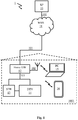
- Figure 1 is a typical subscriber home connected to a service provider.
- the system 1 includes a Service Provider SP 10, connected to a Wide Area Network WAN 11 via link 100, and a subscriber home 1001.
- Subscriber home 1001 includes a gateway GW 12.
- Gateway 12 provides a wired and wireless Access Point (AP) for home network LAN devices Set Top Box STB 13, Digital Television DTV 14, Personal Computer PC 15, and smartphone 16.
- Gateway 12 is provided to the subscriber in the context of a triple-play offer by service provider 10 for combined Internet, telephony and IPTV services.
- Gateway 12 includes several network interfaces, a first network interface enabling connection 101 with WAN 11, a second network interface enabling wired connection 103 with LAN devices 13 and 14, and a third network interface enabling wireless connections 102 with PC 15 and smartphone 16.
- a failure of link 101 between the subscriber gateway 12 and the service provider 10 can be very annoying to a subscriber as all services, Internet, telephony, and IPTV are affected. Such failures account for a high proportion of calls to the service provider's helpdesk.
- FIG 2 is a sequence diagram of WiFi (a trademark of the Wi-Fi Alliance, a technology for wireless LAN based on IEEE 802.11 standards) communication set up between PC 15 (or smartphone 16 ) and gateway 12.
- PC 15 is a mobile station (STA)
- gateway 12 is an access point (AP).
- the mobile station PC 15 starts out as being not authenticated and not associated.
- the mobile station PC 15 broadcasts probe request messages 200 to discover WiFi networks in its proximity. These probe requests advertise the mobile station supported data rates and WiFi capabilities.
- the probe request is transmitted to destination layer-2 address and BSSID (Media Access Control (MAC) address or hardware address of the WiFi chipset running on a wireless access point) of FF:FF:FF:FF:FF and all AP's that receive the message will respond.
- SSID, wireless network name
- the mobile station PC 15 chooses (automatically according to a preference, or based on a manual user choice) a network from the probe responses it receives and the association process starts.
- the mobile station sends 202 authentication information (authentication frame) to the chosen AP (here, to GW 12 ).
- Access point GW 12 receives the authentication frame and responds 203 to the mobile station PC 15.
- the mobile station PC 15 transmits an association request 204 to the chosen access point GW 12.
- Access point GW 12 receives the association request 204 and responds with an association response 205.
- Authentication and association request frames and replies have a format known in the art and are not further detailed here.
- the mobile station PC 15 is now fully associated with access point GW 12 and data transfer starts 206.
- the probe requests are transmitted on all channels and the transmission of probe requests is a preamble to an association between a station and an access point. "Probing" or transmitting probe requests is commonly used in IEEE802.11 to achieve a plurality of goals, such as active scanning for present networks, but also for presence detection and link activity detection.
- Figure 3 is a network infrastructure including several subscribers to a same service provider.
- the infrastructure 3 includes a first home 1001 of a first subscriber and a second home 3001 of a second subscriber.
- Second home 3001 includes a second gateway 32.
- the first gateway 12 in the first home 1001 is disconnected from the WAN because link 101 is broken.
- the second gateway 32 in the second home 3001 is connected to the WAN 11 via a link 301.
- the second gateway 32 in the second home 3001 further includes a wireless network 302. Gateways 12 and 32 in respectively the first home 1001 and in the second home 3001 are within WiFi communication range of each other.
- a gateway as mentioned in the following is also a (wireless) access point.
- a wireless access point is a networking hardware device that allows a wireless network compliant device to connect to a network. Therefore, the present principles may apply to other types of access points than gateways, such as mobile devices acting as a wireless access point, e.g., offering a WiFi or WiMAX wireless access point to LAN devices and a 4G/5G/LTE wireless connection to a WLAN for the LAN devices connected to it.
- FIG. 4 is a sequence diagram illustrating an embodiment of a method of connectivity failure reporting per some principles of the present disclosure.
- the embodiment includes transmission of probe request distress messages (distress messages), i.e., probe request messages with a specific payload, which, when received by an access point, are identified by their specific payload as being distress messages.
- a fault monitor function in gateway 12 in the first home 1001 detects a prolonged interruption or severe communication errors in its communication with SP 10 via link 101, which prevents gateway 12 from communicating with service provider SP 10. Similar to messages 200 with reference to figure 2 , gateway 12 broadcasts probe request distress messages 400 - 402 on all RF channels 1 to n, in the hope of the probe request distress message to be received by a gateway within reach of the RF signal.
- the probe request distress messages transmitted are different from messages 200 in that these are probe request messages with a specific payload.
- the specific payload enables identification by a receiving access point/gateway as being distress messages.
- a gateway 42 is not within RF signal reach and does not receive the probe request distress message transmitted by gateway 12. Alternatively, gateway 42 may be within RF signal reach and receives the probe request distress message from gateway 12 but discards it as gateway 42 is not a gateway of a subscriber to a service offer from service provider SP 10.
- Gateway 32 extracts 404 information from the probe request distress message received, such as identification information of gateway 12 and further information related to the nature of the failure as present in the payload of the probe request distress message.
- Gateway 12 may include further information in a failure report message that it transmits 405 over link 301 to service provider SP 10.
- a gateway/access point receiving a distress message and transmitting the failure report message is also referred to as the 'forwarding' gateway/access point hereinafter.
- Service provider SP 10 receives the failure report and is thereby informed of the connectivity failure of gateway 12 without any user intervention. This mechanism advantageously enables the service provider to be aware of such problems and their nature even in the absence of the subscriber, e.g., when the subscriber is not using his gateway.
- the service provider may conclude that the problem is caused by a failing router or otherwise failing communication link between the router and the service provider in the communication path between the service provider and the plurality of distressed gateways.
- the service provider's service platform can take appropriate measures such as rebooting a failing router or Dynamic Host Configuration Protocol (DHCP) server in the network path to gateway 12, downloading and installing a new router software or DHCP server software, or physical replacing or repairing a network equipment in the communication link between the distressed gateway/access point and the service provider or physically replacing or repairing the communication link diagnosed as failing.
- DHCP Dynamic Host Configuration Protocol
- Gateways are per definition access points and often do not have the software nor the hardware (wireless communication chipset) required to be stations.
- the broadcasting of probe requests by access points is used by access points to scan for and determine least used channels, and the appropriate access point software and hardware (wireless communication chipset) is thus provided for the scan function.
- the feature, according to the present principles, of broadcasting of distress messages based on broadcasting of probe requests by an access point does therefore advantageously not require hardware modifications, nor does it require important software modifications. As such, the present principles can be easily implemented as a high-level upgrade destined to a heterogenous set of gateways.
- FIG. 5 is an example probe request format as specified in the IEEE802.11 standard.
- the specific payload that makes it a probe request distress message is included in the Vendor Specific field for compatibility with IEEE802.11. Vendor specific fields are formatted as follows:
- OUI is an Organization Specific Identifier.
- the vendor-specific tag (1) can be repeated several times, until the probe request frame size is exhausted.
- the probe request frame size can be up to 2300 bytes, so it can be assumed that 2000 bytes are available for the specific payload. Roughly 1920 bytes of payload data is then available after subtraction of header information.
- a single payload message is used.
- OUI in the probe request distress message may represent the company/brand of the device issuing the message or the service provider having provided the device and from which a user of the device has subscribed to a service offer.
- probe request distress message An incremental numerical value (sequence number) is used for the vendor specific type field, so that probe request distress messages can be ordered; e.g., first probe request distress message has a numerical value of 0, the last probe request distress message has a numerical value of n.
- sequence number For the example probe request distress message, the ⁇ data> field is organized as follows:
- Digital message signature and device certificate are security related fields are not further described here and can be formatted according to techniques known in the art.
- TLV Type-Length Value
- a probe request distress message format is included as an example.
- a probe request distress message may have any different format, proprietary or standardized, but would at least require that the message is understood by a receiving gateway as being a distress message. Therefore, such message would comprise information representative of the message being a distress message.
- the probe request distress message would at least include information (device identifier) that would enable a service provider receiver of the message to identify the distressed gateway in the network.
- the distressed gateway includes, as mentioned in the above example distress message format, its last used IP address in the probe request distress messages that it broadcasts.
- the distressed gateway includes, , information enabling to identify the service provider. This enables a receiver device of the distress message to identify for which service provider the distress message is destined, and may be advantageous when receiver devices only forward distress messages destined to its 'own' provider and discard others. According to a particular embodiment, this information is included in the probe request distress message as an additional field. According to a particular embodiment, the OUI is used to include this information.
- a receiver device of a distress message verifies the service provider information with its own service provider and if it is the same, it transmits a probe response message with the same service provider information to the distressed gateway.
- the distressed gateway receiving a probe response verifies if the service provider information in the probe response match to its 'own' service provider. If they match, the distressed gateway 'knows' that the distress message was received by a 'friendly' gateway present on the specific channel on which the distress message was broadcasted and that the distress message will be forwarded by the friendly gateway to the provider IP address in the distress message.
- the distressed gateway includes its Media Access Control address of the concerned WAN interface (of the failing communication link) in the broadcasted probe request distress messages.
- the MAC address is a unique identifier assigned to network interfaces of a device. MAC addresses are used as a network address for most IEEE802 network technologies, including Ethernet and WiFi. MAC addresses are most often assigned by the manufacturer of a Network Interface Controller (NIC) in a device and are stored in its hardware. When a MAC address is assigned by the NIC device manufacturer, it usually encodes the manufacturer's registered identification number and may be referred to as the burned-in address (BIA). It may also be known as an Ethernet hardware address (EHA) or hardware address. This address can be contrasted to the previous mentioned IP address, which is assigned to the device during an IP address negotiation e.g., via the DHCP protocol, and which therefore may vary.
- BIOS Network Interface Controller
- the distressed gateway includes its serial number in the broadcasted probe request distress messages.
- the broadcasted probe request distress messages include further data enabling failure diagnostics by the service provider's service platform.
- Such data may include Bit Error Rate (BER), number of lost packets, signal strength, or any other data that may be helpful for diagnosing the cause of the communication problem encountered.
- BER Bit Error Rate
- This information may be formatted according to TR-069 or SNMP, for example.
- the broadcasted probe request distress messages include sequence numbers in case of the report data being too voluminous to be included in the payload of one probe request distress message.
- the information in the broadcasted probe request distress messages is compressed for size reduction.
- the probe request distress messages are broadcasted on a selected number of channels only or on a single selected channel. While in principle the above discussed scan for least used channels is used by prior art access points/gateways to determine least used channels and for using these channels for wireless communication with its wireless LAN devices with the aim to avoid data collision with channels used by neighboring access points, the result of such scan is surprisingly and advantageously used according to the present principles to select one or more most used channels that are most used by neighboring access points and to broadcast probe request messages on the selected one or more most used channel(s).
- This embodiment advantageously improves the efficiency of the broadcasting of probe request distress messages as it targets the broadcast on channels on which it is likely to find a neighboring gateway that uses one of the selected channels and that listens on one of the selected channels, and avoids occupying unused channels and wasting time and energy on broadcasting distress messages on channels on which no neighbor device is listening anyway.
- the previously discussed scan for most used channels is performed when an anomaly is detected on the main communication link between the gateway and the service provider in the WAN.
- the distressed gateway can target its distress messages to an updated selection of one or more most used channel(s) and improve the efficiency of the broadcasting of distress messages.
- the previously discussed scan for most used channels is performed regularly during the duration of the broadcasting of distress messages to adapt to changes in the list of most used channels.
- the distressed gateway pauses or stops broadcasting distress messages after expiration of a time out period. This advantageously avoids that the broadcasting of distress messages perturbs the communication between neighboring gateways and their LAN devices.
- FIG. 6 is a sequence diagram illustrating a further embodiment of a method of connectivity failure reporting per some principles of the present disclosure.
- the embodiment includes creation of a two-way communication path between a distressed gateway and a neighboring gateway and ultimately a service provider's service center based solely on the probe request mechanism.
- the service provider After having received the failure report 405 from gateway GW 32 neighboring the distressed gateway GW 12, the service provider sends a distress message acknowledge 600 to GW 32.
- the gateway 32 informs the distressed gateway GW 12 of the receipt of the distress message acknowledge in the form of a probe request message 601 with a specific payload marking it as a distress message receipt acknowledge by broadcasting it on a channel on which the distress message was received.
- this enables the distressed gateway to learn that the distress message has been received and has been considered.
- the broadcasting of distress messages is stopped when a distress message receipt acknowledge is received.
- the distress message acknowledge includes information related to the identity of the forwarding gateway, here GW 32.
- this information includes an SSID (network name) of the wireless network of the forwarding gateway (here GW 32). This enables the distressed gateway to identify the network used by the forwarding gateway and may eventually useful for any further communication between the distressed gateway and the forwarding gateway.
- SSID network name
- the transmission of the failure report 405 and the receipt of the acknowledge message from the service provider 600 are according to a remote management protocol such as SNMP or TR-069.
- the distress message receipt acknowledge message comprises further information such as an indication of a cause of the communication failure between the service provider and the distressed gateway and an expected time for return to normal operation.
- information can be advantageously being shown in a popup message on a display device in the LAN to keep a subscriber to the services offering of the service provider informed about the status of the communication problems encountered and improves customer satisfaction and avoids overloading call centers and helpdesks if many subscribers are experiencing communication problems caused by an important failure in the network.
- the distress message receipt acknowledge message comprises further information such as instructions and updates for the distressed device that would enable the distressed device to repair a local cause of the communication failure.
- probe request distress message acknowledge messages may include sequence numbers if the payload size is insufficient for the further information to be included in one probe request.
- the further information is transmitted to the distressed device in a series of probe requests having the distressed device's SSID and having following sequence numbers and each message of the series preferably including the first and the last sequence number.
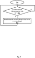
- FIG. 7 is a flow chart 700 of an embodiment of a method of connectivity failure reporting per the principles of the present disclosure as implemented by the access point detecting a communication failure with the service provider.
- the method is for example implemented by gateway 12 of figure 3 .
- Step 701 is repeated if no communication failure is detected ( 701 -N) .
- the first access point 12 broadcasts in a step 702 probe request messages on one or more wireless communication channels.
- the broadcasted probe request messages are particular probe request messages in that they have a specific payload that enables one or more second access points 32 as distress messages, that are representative of a reporting of a failure of the communication on the communication link 101 between the first access point 12 and the service provider 10.
- the one or more second access points 32 receiving the distress message may report the communication failure to the service provider 10, e.g., gateway 32 may report the communication failure to service provider 10 using its own communication link 301.
- FIG 8 is an embodiment of an access point 12 suitable for implementing the method per the principles of the present disclosure.
- the device 12 includes a processor or central processor or processing unit 800, a memory 801, a network interface 802 for connection of the access point to the WAN and to service provider 10 via communication link 101, and a network interface 803 for connection to LAN devices 13-16.
- Network interface 803 is split into two network interfaces 803a and 803b, for respectively wireless communication and wired communication with LAN devices 13-16 e.g., network interface 803a for wireless WiFi connections with devices 15 and 16 and network interface 803b for wired Ethernet connection with devices 13 and 14.
- Processor 800 detects communication failures on the communication link 101 with service provider 10.
- the network interface 803a is used for broadcasting probe request distress messages on one or more wireless communication channels, which may be received by one or more neighboring access points (e.g., access point 32) which will report the failure of communication link 101 to service provider 10 via their own communication link with service provider 10 (e.g., via communication link 301).
- neighboring access points e.g., access point 32
- aspects of the principles of the present disclosure can be embodied as a system, method or computer readable medium. Accordingly, aspects of the principles of the present disclosure can take the form of an entirely hardware embodiment, an entirely software embodiment (including firmware, resident software, micro-code and so forth), or an embodiment combining hardware and software aspects that can all generally be defined to herein as a "circuit", "module” or “system”. Furthermore, aspects of the principles of the present disclosure can take the form of a computer readable storage medium. Any combination of one or more computer readable storage medium(s) can be utilized.
- a computer readable storage medium can take the form of a computer readable program product embodied in one or more computer readable medium(s) and having computer readable program code embodied thereon that is executable by a computer.
- a computer readable storage medium as used herein is considered a non-transitory storage medium given the inherent capability to store the information therein as well as the inherent capability to provide retrieval of the information there from.
- a computer readable storage medium can be, for example, but is not limited to, an electronic, magnetic, optical, electromagnetic, infrared, or semiconductor system, apparatus, or device, or any suitable combination of the foregoing. Some or all aspects of the storage medium may be remotely located (e.g., in the 'cloud').
Landscapes
- Engineering & Computer Science (AREA)
- Computer Networks & Wireless Communication (AREA)
- Signal Processing (AREA)
- Computer Security & Cryptography (AREA)
- Health & Medical Sciences (AREA)
- Cardiology (AREA)
- General Health & Medical Sciences (AREA)
- Mobile Radio Communication Systems (AREA)
- Small-Scale Networks (AREA)
- Data Exchanges In Wide-Area Networks (AREA)
Abstract
When a failure is detected of a communication link between a wireless access point and a service provider providing services to devices in proximity of said wireless access point, probe request messages are broadcasted on one or more wireless communication channels. The broadcasted probe request messages comprise a particular payload enabling them to be identified as being distress messages reporting a failure of the communication link. Another wireless access point within wireless communication reach receiving the distress message may transfer a communication link failure report to the service provider in place of the wireless access point of which the communication link fails.
Description
- The present disclosure generally relates to the field of reporting of communication failure experienced by a device, for diagnostics and repair.
- Any background information described herein is intended to introduce the reader to various aspects of art, which may be related to the present embodiments that are described below. This discussion is believed to be helpful in providing the reader with background information to facilitate a better understanding of the various aspects of the present disclosure. Accordingly, it should be understood that these statements are to be read in this light.
- Typically, user terminals such as Set Top Boxes (STB), High-Definition Televisions (HDTV) and Internet Protocol telephone sets will connect to a Service Provider (SP) through a Local Area Network (LAN) controlled by an Access Point (AP) or Gateway (GW) provided by the service provider. The gateway offers wireless and wired communication for connecting the LAN devices. The gateway further has a network interface that enables it to be connected to a Wide Area Network (WAN) for connection to the Internet and in particular for connection to a server of the service provider. The connection to the WAN is for example according to Data Over Cable Service Interface Specification (DOCSIS), Digital Subscriber Line (DSL), Fiber To The Home (FTTH) or Long-Term Evolution (LTE). The gateway may be managed remotely by the service provider via the link using Simple Network Management Protocol (SNMP) or Technical Report 069 (TR-069) like remote device management protocols. For the service provider, a failure of this communication link to the subscriber's gateway seriously disrupts the provision of services to the subscriber. During prolonged failure, the service provider has no means to reach the gateway and diagnose and repair the failure. Typically, in such a case, the subscriber will notice the connection loss and possibly reboot the gateway. If that doesn't help, the subscriber will have to contact the service provider's helpdesk, for example using his mobile phone, and the helpdesk will guide the user through a series of diagnostic tests to find the cause of the connection failure in the hope of being able to restore the lost connection. If the subscriber has no basic technical knowledge, the intervention of the helpdesk can be very difficult. For both the subscriber and the service provider, a loss of the connection between the service provider and the gateway is therefore annoying.
- There is thus a need for a solution to improve detection of connection failure and establishment of connection failure diagnostics that does not require intervention of the subscriber.
- According to one aspect of the present disclosure, there is provided a method of communication failure reporting. The method is implemented by a first access point and incudes detecting a communication failure on a communication link between the first access point and a service provider providing services to first devices in a first network through the first access point; broadcasting probe request messages on at least one wireless communication channel, the probe request messages comprising a payload enabling the probe request messages to be identified by at least one second access point as distress messages representative of a reporting of a communication failure between the first access point and the service provider, for reporting, by the at least one second access point, the communication failure to the service provider.
- According to a further aspect of the method of communication failure reporting, the method further includes selecting, for the broadcasting of probe request messages, at least one wireless communication channel that is used by at least one second access point from which probe response messages are received by the first access point.
- According to a further aspect of the method of communication failure reporting, the method further includes selecting, for the broadcasting of probe request messages, at least one second access point having a same service provider as the first access point, the same service provider being identified from information comprised in the received probe response messages.
- According to a further aspect of the method of communication failure reporting, the payload further comprises a Medium Access Control address of a communication interface of the first access point on which the communication failure is detected.
- According to a further aspect of the method of communication failure reporting, the payload further comprises an Internet Protocol address of the first access point.
- According to a further aspect of the method of communication failure reporting, the payload further comprises parameters of the first access point formatted according to a Technical Report 069 data model.
- According to a further aspect of the method of communication failure reporting, the payload further comprises parameters of the first access point formatted according to a Simple Network Management Protocol.
- The present principles also relate to an access point device comprising a processor, a memory, a first network interface and a second network interface. The processor, the memory, the first and the second network interfaces are configured to detect a communication failure on a communication link via the first network interface between the access point device and a service provider providing services to devices in a first network through the second network interface; and to broadcast probe request messages via the first network interface on at least one wireless communication channel, the probe request messages comprising a payload enabling the probe request messages to be identified by at least one second access point device as distress messages representative of a reporting of a communication failure between the access point device and the service provider, for reporting, by the at least one second access point device, the communication failure to the service provider.
- According to a further aspect of the access point device, the processor, the memory, the first and the second network interfaces are further configured to.
- According to a further aspect of the access point device, the processor, the memory, the first and the second network interfaces are further configured to select, for the broadcast of probe request messages, at least one wireless communication channel that is used by at least one second wireless access point from which probe response messages are received by the access point device.
- According to a further aspect of the access point device, the processor, the memory, the first and the second network interfaces are further configured to select, for the broadcasting of probe request messages, at least one second access point having a same service provider as the first wireless access point, the same service provider being identified from information comprised in the received probe response messages.
- According to a further aspect of the access point device, the processor, the memory, the first and the second network interfaces are further configured to include in the payload a Medium Access Control address of the second communication interface on which the communication failure is detected.
- According to a further aspect of the access point device, the processor, the memory, the first and the second network interfaces are further configured to include in the payload an Internet Protocol address of the access point device.
- According to a further aspect of the access point device, the processor, the memory, the first and the second network interfaces are further configured to include in the payload parameters of the first wireless access point formatted according to a Technical Report 069 data model.
- According to a further aspect of the access point device, the processor, the memory, the first and the second network interfaces are further configured to include in the payload parameters of the first wireless access point formatted according to a Simple Network Management Protocol.
- According to a further aspect of the access point device, the access point device is a home access gateway.
- More advantages of the present disclosure will appear through the description of particular, non-restricting embodiments. To describe the way the advantages of the present disclosure can be obtained, particular descriptions of the present principles are rendered by reference to specific embodiments thereof which are illustrated in the appended drawings. The drawings depict exemplary embodiments of the disclosure and are therefore not to be considered as limiting its scope. The embodiments described can be combined to form particular advantageous embodiments. In the following figures, items with same reference numbers as items already described in a previous figure will not be described again to avoid unnecessary obscuring the disclosure. The embodiments will be described with reference to the following drawings in which:
-
Figure 1 is a typical subscriber home connected to a service provider. -
Figure 2 is a sequence diagram of wireless communication set up between a wireless device and an access point. -
Figure 3 is a network infrastructure including several subscribers to a same service provider. -
Figure 4 is a sequence diagram illustrating an embodiment of a method of connectivity failure reporting per some principles of the present disclosure. -
Figure 5 is an example probe request format. -
Figure 6 is a sequence diagram illustrating a further embodiment of a method of connectivity failure reporting per some principles of the present disclosure. -
Figure 7 is a flow chart of an embodiment of a method of connectivity failure reporting per the principles of the present disclosure as implemented by an access point detecting a communication failure with the service provider. -
Figure 8 is an embodiment of an access point with a processor and memory for implementing the methods per the principles of the present disclosure. - It should be understood that the drawings are for purposes of illustrating the concepts of the disclosure and are not necessarily the only possible configuration for illustrating the disclosure.
- The present description illustrates the principles of the present disclosure. It will thus be appreciated that those skilled in the art will be able to devise various arrangements that, although not explicitly described or shown herein, embody the principles of the disclosure and are included within its spirit and scope.
- All examples and conditional language recited herein are intended for educational purposes to aid the reader in understanding the principles of the disclosure and the concepts contributed by the inventor to furthering the art, and are to be construed as being without limitation to such specifically recited examples and conditions.
- Moreover, all statements herein reciting principles, aspects, and embodiments of the disclosure, as well as specific examples thereof, are intended to encompass both structural and functional equivalents thereof. Additionally, it is intended that such equivalents include both currently known equivalents as well as equivalents developed in the future, i.e., any elements developed that perform the same function, regardless of structure.
-
Figure 1 is a typical subscriber home connected to a service provider. Thesystem 1 includes a Service Provider SP 10, connected to a Wide Area Network WAN 11 vialink 100, and asubscriber home 1001.Subscriber home 1001 includes agateway GW 12. Gateway 12 provides a wired and wireless Access Point (AP) for home network LAN devices Set Top Box STB 13, Digital Television DTV 14, Personal Computer PC 15, andsmartphone 16. Gateway 12 is provided to the subscriber in the context of a triple-play offer byservice provider 10 for combined Internet, telephony and IPTV services. Gateway 12 includes several network interfaces, a first networkinterface enabling connection 101 with WAN 11, a second network interface enablingwired connection 103 withLAN devices wireless connections 102 with PC 15 andsmartphone 16. In thesystem 1, a failure oflink 101 between thesubscriber gateway 12 and theservice provider 10 can be very annoying to a subscriber as all services, Internet, telephony, and IPTV are affected. Such failures account for a high proportion of calls to the service provider's helpdesk. -
Figure 2 is a sequence diagram of WiFi (a trademark of the Wi-Fi Alliance, a technology for wireless LAN based on IEEE 802.11 standards) communication set up between PC 15 (or smartphone 16) andgateway 12. In terms of WiFi,PC 15 is a mobile station (STA), andgateway 12 is an access point (AP). Themobile station PC 15 starts out as being not authenticated and not associated. As part of network discovery, themobile station PC 15 broadcastsprobe request messages 200 to discover WiFi networks in its proximity. These probe requests advertise the mobile station supported data rates and WiFi capabilities. The probe request is transmitted to destination layer-2 address and BSSID (Media Access Control (MAC) address or hardware address of the WiFi chipset running on a wireless access point) of FF:FF:FF:FF:FF:FF and all AP's that receive the message will respond. APs such asgateway 12 receiving the probe request will send aprobe response 201 is sent advertising the Service Set IDentifier (SSID, = wireless network name), supported data rates, encryption types, and wireless capabilities of the AP. Themobile station PC 15 chooses (automatically according to a preference, or based on a manual user choice) a network from the probe responses it receives and the association process starts. The mobile station sends 202 authentication information (authentication frame) to the chosen AP (here, to GW 12).Access point GW 12 receives the authentication frame and responds 203 to themobile station PC 15. Themobile station PC 15 transmits anassociation request 204 to the chosenaccess point GW 12.Access point GW 12 receives theassociation request 204 and responds with anassociation response 205. Authentication and association request frames and replies have a format known in the art and are not further detailed here. Themobile station PC 15 is now fully associated withaccess point GW 12 and data transfer starts 206. The probe requests are transmitted on all channels and the transmission of probe requests is a preamble to an association between a station and an access point. "Probing" or transmitting probe requests is commonly used in IEEE802.11 to achieve a plurality of goals, such as active scanning for present networks, but also for presence detection and link activity detection. -
Figure 3 is a network infrastructure including several subscribers to a same service provider. Theinfrastructure 3 includes afirst home 1001 of a first subscriber and asecond home 3001 of a second subscriber.Second home 3001 includes asecond gateway 32. Thefirst gateway 12 in thefirst home 1001 is disconnected from the WAN becauselink 101 is broken. Thesecond gateway 32 in thesecond home 3001 is connected to theWAN 11 via alink 301. Thesecond gateway 32 in thesecond home 3001 further includes awireless network 302.Gateways first home 1001 and in thesecond home 3001 are within WiFi communication range of each other. - In the following, the terms 'gateway' (GW), 'access point' (AP) and 'wireless access point' (WAP) are used indifferently for meaning the same. This means that a gateway as mentioned in the following is also a (wireless) access point. In computer networking, a wireless access point is a networking hardware device that allows a wireless network compliant device to connect to a network. Therefore, the present principles may apply to other types of access points than gateways, such as mobile devices acting as a wireless access point, e.g., offering a WiFi or WiMAX wireless access point to LAN devices and a 4G/5G/LTE wireless connection to a WLAN for the LAN devices connected to it.
-
Figure 4 is a sequence diagram illustrating an embodiment of a method of connectivity failure reporting per some principles of the present disclosure. The embodiment includes transmission of probe request distress messages (distress messages), i.e., probe request messages with a specific payload, which, when received by an access point, are identified by their specific payload as being distress messages. A fault monitor function ingateway 12 in thefirst home 1001 detects a prolonged interruption or severe communication errors in its communication withSP 10 vialink 101, which preventsgateway 12 from communicating withservice provider SP 10. Similar tomessages 200 with reference tofigure 2 ,gateway 12 broadcasts probe request distress messages 400 - 402 on allRF channels 1 to n, in the hope of the probe request distress message to be received by a gateway within reach of the RF signal. The probe request distress messages transmitted are different frommessages 200 in that these are probe request messages with a specific payload. The specific payload enables identification by a receiving access point/gateway as being distress messages.Figure 4 illustrates receipt of a probe request distress message by only onegateway GW 32. For example, n=8 and a probe request distress message transmitted on channel eight is received, 403, bygateway 32. Agateway 42 is not within RF signal reach and does not receive the probe request distress message transmitted bygateway 12. Alternatively,gateway 42 may be within RF signal reach and receives the probe request distress message fromgateway 12 but discards it asgateway 42 is not a gateway of a subscriber to a service offer fromservice provider SP 10.Gateway 32 extracts 404 information from the probe request distress message received, such as identification information ofgateway 12 and further information related to the nature of the failure as present in the payload of the probe request distress message.Gateway 12 may include further information in a failure report message that it transmits 405 overlink 301 toservice provider SP 10. A gateway/access point receiving a distress message and transmitting the failure report message is also referred to as the 'forwarding' gateway/access point hereinafter.Service provider SP 10 receives the failure report and is thereby informed of the connectivity failure ofgateway 12 without any user intervention. This mechanism advantageously enables the service provider to be aware of such problems and their nature even in the absence of the subscriber, e.g., when the subscriber is not using his gateway. If many failures of a same nature are reported by a number of distressed gateways in a same communication path, the service provider may conclude that the problem is caused by a failing router or otherwise failing communication link between the router and the service provider in the communication path between the service provider and the plurality of distressed gateways. Following analysis of the failure report and possibly analysis of failure reports received from other gateways, the service provider's service platform can take appropriate measures such as rebooting a failing router or Dynamic Host Configuration Protocol (DHCP) server in the network path togateway 12, downloading and installing a new router software or DHCP server software, or physical replacing or repairing a network equipment in the communication link between the distressed gateway/access point and the service provider or physically replacing or repairing the communication link diagnosed as failing. As can be observed, the communication between the distressed gateway and the forwarding gateway does not go beyond the transmission of probe request messages, i.e., there is no association and data exchange between gateways. A complete data communication setup would require the distressed gateway to play the role of a station, seefigure 2 . Gateways are per definition access points and often do not have the software nor the hardware (wireless communication chipset) required to be stations. The broadcasting of probe requests by access points is used by access points to scan for and determine least used channels, and the appropriate access point software and hardware (wireless communication chipset) is thus provided for the scan function. The feature, according to the present principles, of broadcasting of distress messages based on broadcasting of probe requests by an access point does therefore advantageously not require hardware modifications, nor does it require important software modifications. As such, the present principles can be easily implemented as a high-level upgrade destined to a heterogenous set of gateways. -
Figure 5 is an example probe request format as specified in the IEEE802.11 standard. The specific payload that makes it a probe request distress message is included in the Vendor Specific field for compatibility with IEEE802.11. Vendor specific fields are formatted as follows:
<vendor-specific tag> <OUI> <vendor-specific-type> <data> (1)
OUI is an Organization Specific Identifier. The vendor-specific tag (1) can be repeated several times, until the probe request frame size is exhausted. The probe request frame size can be up to 2300 bytes, so it can be assumed that 2000 bytes are available for the specific payload. Roughly 1920 bytes of payload data is then available after subtraction of header information. According to a particular embodiment, a single payload message is used. OUI in the probe request distress message may represent the company/brand of the device issuing the message or the service provider having provided the device and from which a user of the device has subscribed to a service offer. An incremental numerical value (sequence number) is used for the vendor specific type field, so that probe request distress messages can be ordered; e.g., first probe request distress message has a numerical value of 0, the last probe request distress message has a numerical value of n. For the example probe request distress message, the <data> field is organized as follows:
- o Message Type: 1 byte. "Distress message" = 0x01.
- o Authentication information:
- ▪ Device Certificate - 250 bytes;
- ▪ Random number (4 bytes, see next field);
- ▪ Digital message signature: Encryption using the distressed device's private key over a hash of the random number + device certificate (160 bytes if using SHA1);
- o Addressing:
- ▪ Distressed device's MAC Address (if not already included in the certificate): 6 bytes
- ▪ Distressed Device's last known IP address: 4 bytes
- ▪ Service provider's IP address: 4 bytes
- o Distressed device's data for diagnostic purposes:
- ▪ System uptime: 4 bytes
- ▪ Latest log data: 160 bytes of textual data
- ▪ Configuration summary: 240 bytes
- ▪ Link Data: various pieces of device parameters information formatted according to the applicable management data model, e.g. TR-069.
Digital message signature and device certificate are security related fields are not further described here and can be formatted according to techniques known in the art.
Further information may be included in the data field of the probe request distress message, as appropriate to the distressed device and encoded with Type-Length Value (TLV). Other data models than TR-069 may be used, e.g., SNMP.
The above probe request distress message format is included as an example. A probe request distress message may have any different format, proprietary or standardized, but would at least require that the message is understood by a receiving gateway as being a distress message. Therefore, such message would comprise information representative of the message being a distress message. Furthermore, the probe request distress message would at least include information (device identifier) that would enable a service provider receiver of the message to identify the distressed gateway in the network.
According to a particular embodiment, the distressed gateway includes, as mentioned in the above example distress message format, its last used IP address in the probe request distress messages that it broadcasts.
According to a particular embodiment, the distressed gateway includes, , information enabling to identify the service provider. This enables a receiver device of the distress message to identify for which service provider the distress message is destined, and may be advantageous when receiver devices only forward distress messages destined to its 'own' provider and discard others. According to a particular embodiment, this information is included in the probe request distress message as an additional field. According to a particular embodiment, the OUI is used to include this information.
According to a particular embodiment, a receiver device of a distress message verifies the service provider information with its own service provider and if it is the same, it transmits a probe response message with the same service provider information to the distressed gateway. The distressed gateway receiving a probe response verifies if the service provider information in the probe response match to its 'own' service provider. If they match, the distressed gateway 'knows' that the distress message was received by a 'friendly' gateway present on the specific channel on which the distress message was broadcasted and that the distress message will be forwarded by the friendly gateway to the provider IP address in the distress message.
Alternatively or additionally, as mentioned in the above example distress message format, the distressed gateway includes its Media Access Control address of the concerned WAN interface (of the failing communication link) in the broadcasted probe request distress messages. The MAC address is a unique identifier assigned to network interfaces of a device. MAC addresses are used as a network address for most IEEE802 network technologies, including Ethernet and WiFi. MAC addresses are most often assigned by the manufacturer of a Network Interface Controller (NIC) in a device and are stored in its hardware. When a MAC address is assigned by the NIC device manufacturer, it usually encodes the manufacturer's registered identification number and may be referred to as the burned-in address (BIA). It may also be known as an Ethernet hardware address (EHA) or hardware address. This address can be contrasted to the previous mentioned IP address, which is assigned to the device during an IP address negotiation e.g., via the DHCP protocol, and which therefore may vary.
Alternatively or additionally, the distressed gateway includes its serial number in the broadcasted probe request distress messages.
According to a particular embodiment, the broadcasted probe request distress messages include further data enabling failure diagnostics by the service provider's service platform. Such data may include Bit Error Rate (BER), number of lost packets, signal strength, or any other data that may be helpful for diagnosing the cause of the communication problem encountered. This information may be formatted according to TR-069 or SNMP, for example.
According to a particular embodiment, the broadcasted probe request distress messages include sequence numbers in case of the report data being too voluminous to be included in the payload of one probe request distress message.
According to a particular embodiment, the information in the broadcasted probe request distress messages is compressed for size reduction.
According to a particular embodiment that can be advantageously combined with any of the previous described embodiments, the probe request distress messages are broadcasted on a selected number of channels only or on a single selected channel. While in principle the above discussed scan for least used channels is used by prior art access points/gateways to determine least used channels and for using these channels for wireless communication with its wireless LAN devices with the aim to avoid data collision with channels used by neighboring access points, the result of such scan is surprisingly and advantageously used according to the present principles to select one or more most used channels that are most used by neighboring access points and to broadcast probe request messages on the selected one or more most used channel(s). This embodiment advantageously improves the efficiency of the broadcasting of probe request distress messages as it targets the broadcast on channels on which it is likely to find a neighboring gateway that uses one of the selected channels and that listens on one of the selected channels, and avoids occupying unused channels and wasting time and energy on broadcasting distress messages on channels on which no neighbor device is listening anyway.
According to a particular embodiment that can be advantageously combined with any the previously described embodiment, the previously discussed scan for most used channels is performed when an anomaly is detected on the main communication link between the gateway and the service provider in the WAN. This way, the distressed gateway can target its distress messages to an updated selection of one or more most used channel(s) and improve the efficiency of the broadcasting of distress messages. According to a particular embodiment, the previously discussed scan for most used channels is performed regularly during the duration of the broadcasting of distress messages to adapt to changes in the list of most used channels.
According to a particular embodiment, the distressed gateway pauses or stops broadcasting distress messages after expiration of a time out period. This advantageously avoids that the broadcasting of distress messages perturbs the communication between neighboring gateways and their LAN devices.
According to a particular advantageous embodiment, the broadcasting of distress messages is stopped when a distress message receipt acknowledge is received.
According to a particular embodiment, the distress message acknowledge includes information related to the identity of the forwarding gateway, here GW 32. According to a particular embodiment, this information includes an SSID (network name) of the wireless network of the forwarding gateway (here GW 32). This enables the distressed gateway to identify the network used by the forwarding gateway and may eventually useful for any further communication between the distressed gateway and the forwarding gateway.
According to a further embodiment, the transmission of the failure report 405 and the receipt of the acknowledge message from the service provider 600 are according to a remote management protocol such as SNMP or TR-069.
According to a further embodiment, the distress message receipt acknowledge message comprises further information such as an indication of a cause of the communication failure between the service provider and the distressed gateway and an expected time for return to normal operation. Such information can be advantageously being shown in a popup message on a display device in the LAN to keep a subscriber to the services offering of the service provider informed about the status of the communication problems encountered and improves customer satisfaction and avoids overloading call centers and helpdesks if many subscribers are experiencing communication problems caused by an important failure in the network.
According to a further embodiment, the distress message receipt acknowledge message comprises further information such as instructions and updates for the distressed device that would enable the distressed device to repair a local cause of the communication failure. As previously mentioned for probe request distress messages, probe request distress message acknowledge messages may include sequence numbers if the payload size is insufficient for the further information to be included in one probe request. In which case, the further information is transmitted to the distressed device in a series of probe requests having the distressed device's SSID and having following sequence numbers and each message of the series preferably including the first and the last sequence number.
It is to be appreciated that some elements in the drawings may not be used or be necessary in all embodiments. Some operations may be executed in parallel. Embodiments other than those illustrated and/or described are possible. For example, a device implementing the present principles may include a mix of hard- and software.
It is to be appreciated that aspects of the principles of the present disclosure can be embodied as a system, method or computer readable medium. Accordingly, aspects of the principles of the present disclosure can take the form of an entirely hardware embodiment, an entirely software embodiment (including firmware, resident software, micro-code and so forth), or an embodiment combining hardware and software aspects that can all generally be defined to herein as a "circuit", "module" or "system". Furthermore, aspects of the principles of the present disclosure can take the form of a computer readable storage medium. Any combination of one or more computer readable storage medium(s) can be utilized.
Thus, for example, it is to be appreciated that the diagrams presented herein represent conceptual views of illustrative system components and/or circuitry embodying the principles of the present disclosure. Similarly, it is to be appreciated that any flow charts, flow diagrams, state transition diagrams, pseudo code, and the like represent various processes which may be substantially represented in computer readable storage media and so executed by a computer or processor, whether such computer or processor is explicitly shown.
A computer readable storage medium can take the form of a computer readable program product embodied in one or more computer readable medium(s) and having computer readable program code embodied thereon that is executable by a computer. A computer readable storage medium as used herein is considered a non-transitory storage medium given the inherent capability to store the information therein as well as the inherent capability to provide retrieval of the information there from. A computer readable storage medium can be, for example, but is not limited to, an electronic, magnetic, optical, electromagnetic, infrared, or semiconductor system, apparatus, or device, or any suitable combination of the foregoing. Some or all aspects of the storage medium may be remotely located (e.g., in the 'cloud'). It is to be appreciated that the following, while providing more specific examples of computer readable storage mediums to which the present principles can be applied, is merely an illustrative and not exhaustive listing, as is readily appreciated by one of ordinary skill in the art: a hard disk, a read-only memory (ROM), an erasable programmable read-only memory (EPROM or Flash memory), a portable compact disc read-only memory (CD-ROM), an optical storage device, a magnetic storage device, or any suitable combination of the foregoing.
Claims (15)
- A method (600) of communication failure reporting, characterized in that said method is implemented by a first access point (12), said method comprising:detecting (701) a communication failure on a communication link (101) between said first access point and a service provider (10) providing services to first devices (13-16) in a first network through said first access point;broadcasting (702) probe request messages on at least one wireless communication channel, said probe request messages comprising a payload enabling said probe request messages to be identified by at least one second access point (32) as distress messages representative of a reporting of a communication failure between said first access point and said service provider, for reporting, by said at least one second access point, said communication failure to said service provider.
- The method according to claim 1, further comprising selecting, for said broadcasting of probe request messages, at least one wireless communication channel that is used by at least one second access point from which probe response messages are received by said first access point.
- The method according to claim 2, further comprising selecting, for said broadcasting of probe request messages, at least one second access point having a same service provider as said first access point, said same service provider being identified from information comprised in said received probe response messages.
- The method according to any of claims 1 to 3, wherein said payload further comprises a Medium Access Control address of a communication interface of said first access point on which said communication failure is detected.
- The method according to any of claims 1 to 4, wherein said payload further comprises an Internet Protocol address of said first access point.
- The method according to any of claims 1 to 5, wherein said payload further comprises parameters of said first access point formatted according to a Technical Report 069 data model.
- The method according to any of claims 1 to 5, wherein said payload further comprises parameters of said first access point formatted according to a Simple Network Management Protocol.
- An access point device (12), the access point device comprising a processor (800), a memory (801), a first network interface (803) and a second network interface (802), configured to:detect a communication failure on a communication link (101) via said first network interface between said access point device and a service provider (10) providing services to devices (13-16) in a first network through said second network interface; andbroadcast probe request messages (400-402) via said first network interface on at least one wireless communication channel, said probe request messages comprising a payload enabling said probe request messages to be identified by at least one second access point device (32) as distress messages representative of a reporting of a communication failure between said access point device and said service provider, for reporting, by said at least one second access point device, said communication failure to said service provider.
- The access point device according to claim 8, wherein said processor, said memory, said first network interface and said second network interface are further configured to select, for said broadcast of probe request messages, at least one wireless communication channel that is used by at least one second wireless access point from which probe response messages are received by said access point device.
- The wireless access point device according to claim 9, wherein said processor, said memory, said first network interface and said second network interface are further configured to select, for said broadcasting of probe request messages, at least one second access point having a same service provider as said first wireless access point, said same service provider being identified from information comprised in said received probe response messages.
- The access point device according to any of claims 8 to 10, wherein said processor, said memory, said first network interface and said second network interface are further configured to include in said payload a Medium Access Control address of said second communication interface on which said communication failure is detected.
- The access point device according to any of claims 8 to 11, wherein said processor, said memory, said first network interface and said second network interface are further configured to include in said payload an Internet Protocol address of said access point device.
- The access point device according to any of claims 8 to 12, wherein said processor, said memory, said first network interface and said second network interface are further configured to include in said payload parameters of said first wireless access point formatted according to a Technical Report 069 data model.
- The access point device according to any of claims 8 to 12, wherein said processor, said memory, said first network interface and said second network interface are further configured to include in said payload parameters of said first wireless access point formatted according to a Simple Network Management Protocol.
- The wireless access point device according to any of claims 8 to 14, wherein said access point device is a home access gateway.
Priority Applications (5)
| Application Number | Priority Date | Filing Date | Title |
|---|---|---|---|
| EP17305808.2A EP3422637A1 (en) | 2017-06-28 | 2017-06-28 | Method of communication failure reporting and corresponding apparatus |
| EP18178513.0A EP3422638B1 (en) | 2017-06-28 | 2018-06-19 | Method of communication failure reporting and corresponding apparatus |
| US16/017,979 US10904777B2 (en) | 2017-06-28 | 2018-06-25 | Method of communication failure reporting and corresponding apparatus |
| CN201810694939.0A CN109150650B (en) | 2017-06-28 | 2018-06-28 | Method for reporting communication faults and corresponding equipment |
| BR102018013362-4A BR102018013362A2 (en) | 2017-06-28 | 2018-06-28 | communication failure warning method and corresponding device |
Applications Claiming Priority (1)
| Application Number | Priority Date | Filing Date | Title |
|---|---|---|---|
| EP17305808.2A EP3422637A1 (en) | 2017-06-28 | 2017-06-28 | Method of communication failure reporting and corresponding apparatus |
Publications (1)
| Publication Number | Publication Date |
|---|---|
| EP3422637A1 true EP3422637A1 (en) | 2019-01-02 |
Family
ID=59315534
Family Applications (2)
| Application Number | Title | Priority Date | Filing Date |
|---|---|---|---|
| EP17305808.2A Withdrawn EP3422637A1 (en) | 2017-06-28 | 2017-06-28 | Method of communication failure reporting and corresponding apparatus |
| EP18178513.0A Active EP3422638B1 (en) | 2017-06-28 | 2018-06-19 | Method of communication failure reporting and corresponding apparatus |
Family Applications After (1)
| Application Number | Title | Priority Date | Filing Date |
|---|---|---|---|
| EP18178513.0A Active EP3422638B1 (en) | 2017-06-28 | 2018-06-19 | Method of communication failure reporting and corresponding apparatus |
Country Status (4)
| Country | Link |
|---|---|
| US (1) | US10904777B2 (en) |
| EP (2) | EP3422637A1 (en) |
| CN (1) | CN109150650B (en) |
| BR (1) | BR102018013362A2 (en) |
Cited By (3)
| Publication number | Priority date | Publication date | Assignee | Title |
|---|---|---|---|---|
| EP3706370A1 (en) * | 2019-03-08 | 2020-09-09 | Mist Systems, Inc. | Method for conveying ap error codes over ble advertisements |
| CN113905050A (en) * | 2021-08-30 | 2022-01-07 | 深圳市联洲国际技术有限公司 | Method, device and system for detecting internet access information |
| WO2022221036A1 (en) * | 2021-04-13 | 2022-10-20 | Arris Enterprises Llc | Notifying service provider of wi-fi gateway issues |
Families Citing this family (15)
| Publication number | Priority date | Publication date | Assignee | Title |
|---|---|---|---|---|
| US11190395B2 (en) * | 2018-08-08 | 2021-11-30 | International Business Machines Corporation | Alerting service provider of failed network connectivity by IoT-enabled modem |
| JP6974632B2 (en) * | 2018-11-05 | 2021-12-01 | スラック テクノロジーズ エルエルシー | Maintaining minimal interface functionality in the absence of push-based communication connections in group-based communication systems |
| EP3935462B1 (en) * | 2019-03-08 | 2023-08-16 | British Telecommunications public limited company | Vehicle management |
| CN110418366B (en) * | 2019-06-14 | 2024-09-03 | 武汉慧联无限科技有限公司 | Fault reporting device and method |
| CN110445651A (en) * | 2019-08-08 | 2019-11-12 | 珠海格力电器股份有限公司 | Method and device for marginalizing data based on concentrator |
| US11115225B2 (en) * | 2019-11-20 | 2021-09-07 | Verizon Patent And Licensing Inc. | Remote home router communication via set-top box |
| EP4193346A1 (en) * | 2020-08-07 | 2023-06-14 | Ofinno, LLC | Connection control |
| CN112073234B (en) * | 2020-09-02 | 2024-06-28 | 腾讯科技(深圳)有限公司 | Fault detection method, device, system, equipment and storage medium |
| WO2022056734A1 (en) * | 2020-09-16 | 2022-03-24 | Arris Enterprises Llc | Method for remote debugging of gateway when wan connection of gateway is lost |
| CN115706988A (en) * | 2021-08-10 | 2023-02-17 | 中国移动通信有限公司研究院 | Network processing method, system and related equipment |
| CN113852526A (en) * | 2021-08-24 | 2021-12-28 | 天翼数字生活科技有限公司 | WiFi-based home network diagnosis method and system |
| CN113873560B (en) * | 2021-09-29 | 2024-11-22 | 中国电信股份有限公司 | Network failure processing method and device |
| US12082007B2 (en) * | 2022-01-20 | 2024-09-03 | Red Hat, Inc. | Mayday-relay mechanism in a mesh network |
| EP4550745A1 (en) * | 2023-10-31 | 2025-05-07 | Vodafone Group Services Limited | Router connectivity enhancements |
| US20260019808A1 (en) * | 2024-07-12 | 2026-01-15 | Cisco Technology, Inc. | Diagnosis exchange protocols |
Citations (3)
| Publication number | Priority date | Publication date | Assignee | Title |
|---|---|---|---|---|
| KR20140148286A (en) * | 2013-06-21 | 2014-12-31 | 주식회사 케이티 | Methods for reporting the connection failure information of a wireless LAN and Apparatuses thereof |
| EP2919505A1 (en) * | 2012-11-04 | 2015-09-16 | LG Electronics Inc. | Method by which terminal for supporting multiple radio access technologies recovers when radio link failure has occurred and device for same |
| EP3043595A1 (en) * | 2013-08-23 | 2016-07-13 | LG Electronics Inc. | Method for managing link failure of user equipment simultaneously connected to multiple rats and device for performing same |
Family Cites Families (18)
| Publication number | Priority date | Publication date | Assignee | Title |
|---|---|---|---|---|
| US7035202B2 (en) * | 2001-03-16 | 2006-04-25 | Juniper Networks, Inc. | Network routing using link failure information |
| CN1685670B (en) * | 2002-10-03 | 2010-05-26 | 思科技术公司 | Method for wireless station to determine network metrics prior to association with access point |
| US20040181692A1 (en) * | 2003-01-13 | 2004-09-16 | Johanna Wild | Method and apparatus for providing network service information to a mobile station by a wireless local area network |
| US20060153085A1 (en) * | 2004-12-27 | 2006-07-13 | Willins Bruce A | Method and system for recovery from access point infrastructure link failures |
| US20070064660A1 (en) * | 2005-09-16 | 2007-03-22 | Qi Emily H | Techniques for enhanced transition from access point to access point by a mobile wireless device |
| US20080080365A1 (en) | 2006-09-28 | 2008-04-03 | Weeresinghe Ranjith Thomas Mah | Wireless Access Point Failover System and Method |
| US8621067B2 (en) | 2009-09-10 | 2013-12-31 | At&T Intellectual Property I, Lp | Apparatus and method for managing communications |
| US8811152B2 (en) * | 2009-10-29 | 2014-08-19 | At&T Intellectual Property I, L.P. | System and method to support secondary channel connection from residential gateway to service provider network |
| CN102740337B (en) | 2011-04-12 | 2015-08-12 | 中兴通讯股份有限公司 | The long-distance maintenance method of base station and system |
| WO2013085366A1 (en) * | 2011-12-08 | 2013-06-13 | 엘지전자 주식회사 | Method and apparatus for setting up link at high-speed in wireless communication system |
| EP2739093A1 (en) | 2012-11-29 | 2014-06-04 | British Telecommunications public limited company | Restoration of network access |
| EP2739081A1 (en) * | 2012-11-29 | 2014-06-04 | British Telecommunications public limited company | Network access restoration |
| CN105794253B (en) * | 2013-11-28 | 2017-11-28 | 英国电讯有限公司 | The method of WAP and the loss of report connection |
| CN103874114B (en) | 2014-03-19 | 2018-06-12 | 新华三技术有限公司 | A kind of AP fault handling methods, AP equipment and AC equipment |
| US10154423B2 (en) * | 2014-06-27 | 2018-12-11 | Google Llc | End-to-end network diagnostics |
| CN104935466B (en) * | 2015-06-17 | 2019-05-07 | 新华三技术有限公司 | A kind of fault handling method and device |
| CN105722121B (en) * | 2016-03-30 | 2019-03-22 | 中国联合网络通信集团有限公司 | Gateway Working mode switching method and device, gateway, wearable device |
| CN106255180A (en) * | 2016-10-18 | 2016-12-21 | 青岛海信宽带多媒体技术有限公司 | The method of attachment of wireless network access point and device |
-
2017
- 2017-06-28 EP EP17305808.2A patent/EP3422637A1/en not_active Withdrawn
-
2018
- 2018-06-19 EP EP18178513.0A patent/EP3422638B1/en active Active
- 2018-06-25 US US16/017,979 patent/US10904777B2/en active Active
- 2018-06-28 CN CN201810694939.0A patent/CN109150650B/en active Active
- 2018-06-28 BR BR102018013362-4A patent/BR102018013362A2/en not_active Application Discontinuation
Patent Citations (3)
| Publication number | Priority date | Publication date | Assignee | Title |
|---|---|---|---|---|
| EP2919505A1 (en) * | 2012-11-04 | 2015-09-16 | LG Electronics Inc. | Method by which terminal for supporting multiple radio access technologies recovers when radio link failure has occurred and device for same |
| KR20140148286A (en) * | 2013-06-21 | 2014-12-31 | 주식회사 케이티 | Methods for reporting the connection failure information of a wireless LAN and Apparatuses thereof |
| EP3043595A1 (en) * | 2013-08-23 | 2016-07-13 | LG Electronics Inc. | Method for managing link failure of user equipment simultaneously connected to multiple rats and device for performing same |
Cited By (11)
| Publication number | Priority date | Publication date | Assignee | Title |
|---|---|---|---|---|
| EP3706370A1 (en) * | 2019-03-08 | 2020-09-09 | Mist Systems, Inc. | Method for conveying ap error codes over ble advertisements |
| CN111669713A (en) * | 2019-03-08 | 2020-09-15 | 水雾系统股份有限公司 | Method for conveying AP error codes in BLE advertisements |
| US10862742B2 (en) | 2019-03-08 | 2020-12-08 | Juniper Networks, Inc. | Method for conveying AP error codes over BLE advertisements |
| CN111669713B (en) * | 2019-03-08 | 2021-09-10 | 瞻博网络公司 | Method for transmitting AP error codes in BLE advertisements |
| CN113727284A (en) * | 2019-03-08 | 2021-11-30 | 瞻博网络公司 | Method for transmitting AP error codes in BLE advertisements |
| US11575562B2 (en) | 2019-03-08 | 2023-02-07 | Juniper Networks, Inc. | Method for conveying AP error codes over BLE advertisements |
| EP4297489A3 (en) * | 2019-03-08 | 2024-02-28 | Juniper Networks, Inc. | Method for conveying ap error codes over ble advertisements |
| US12470456B2 (en) | 2019-03-08 | 2025-11-11 | Juniper Networks, Inc. | Method for conveying AP error codes over BLE advertisements |
| WO2022221036A1 (en) * | 2021-04-13 | 2022-10-20 | Arris Enterprises Llc | Notifying service provider of wi-fi gateway issues |
| CN113905050A (en) * | 2021-08-30 | 2022-01-07 | 深圳市联洲国际技术有限公司 | Method, device and system for detecting internet access information |
| CN113905050B (en) * | 2021-08-30 | 2023-07-18 | 成都市联洲国际技术有限公司 | Method, device and system for detecting internet access information |
Also Published As
| Publication number | Publication date |
|---|---|
| EP3422638B1 (en) | 2022-10-26 |
| BR102018013362A2 (en) | 2019-01-15 |
| US20190007847A1 (en) | 2019-01-03 |
| CN109150650A (en) | 2019-01-04 |
| US10904777B2 (en) | 2021-01-26 |
| EP3422638A1 (en) | 2019-01-02 |
| CN109150650B (en) | 2023-08-11 |
Similar Documents
| Publication | Publication Date | Title |
|---|---|---|
| EP3422638B1 (en) | Method of communication failure reporting and corresponding apparatus | |
| US10447533B2 (en) | System and method for managing access point functionality and configuration | |
| US12563412B2 (en) | Easymesh configuration of AP using IEEE 1905.1 | |
| EP2951953B1 (en) | Method of managing zigbee network in the internet of things | |
| US8125914B2 (en) | Scaled Ethernet OAM for mesh and hub-and-spoke networks | |
| EP4087320B1 (en) | Method for channel switching in wireless mesh network, and wireless device | |
| KR101737110B1 (en) | Diagnosing and resolving wireless network malfunctions | |
| EP2680634B1 (en) | Method, device and system for signalling tracing | |
| US20110045835A1 (en) | Self-configuration of femtocell access points (fap) | |
| EP3145161A1 (en) | Automatic wireless access network configuration synchronization method and apparatus | |
| CN109548019B (en) | Network distribution method and system | |
| US10103932B2 (en) | Technique for assisting remote diagnosis of an access gateway | |
| CN113709846A (en) | Method and apparatus for automatically triggering a sensorless network of user equipment | |
| US9948497B2 (en) | System for and method of automatically discovering and configuring NIDs | |
| CN102857953B (en) | Self-configuration method and device of base station | |
| KR100965626B1 (en) | Method of testing for wireless LAN system and test protocol | |
| US20250310177A1 (en) | Tag-Based Network-Wide Troubleshooting | |
| US20240348490A1 (en) | Access point fault and error code communication | |
| CN107342919A (en) | Terminal device service correlating method | |
| WO2025196798A1 (en) | System for identifying information associated with a customer premises equipment and method thereof |
Legal Events
| Date | Code | Title | Description |
|---|---|---|---|
| PUAI | Public reference made under article 153(3) epc to a published international application that has entered the european phase |
Free format text: ORIGINAL CODE: 0009012 |
|
| AK | Designated contracting states |
Kind code of ref document: A1 Designated state(s): AL AT BE BG CH CY CZ DE DK EE ES FI FR GB GR HR HU IE IS IT LI LT LU LV MC MK MT NL NO PL PT RO RS SE SI SK SM TR |
|
| AX | Request for extension of the european patent |
Extension state: BA ME |
|
| STAA | Information on the status of an ep patent application or granted ep patent |
Free format text: STATUS: THE APPLICATION IS DEEMED TO BE WITHDRAWN |
|
| 18D | Application deemed to be withdrawn |
Effective date: 20190703 |