EP3422380A1 - Disconnecting switch having anti-icing device - Google Patents
Disconnecting switch having anti-icing device Download PDFInfo
- Publication number
- EP3422380A1 EP3422380A1 EP16891036.2A EP16891036A EP3422380A1 EP 3422380 A1 EP3422380 A1 EP 3422380A1 EP 16891036 A EP16891036 A EP 16891036A EP 3422380 A1 EP3422380 A1 EP 3422380A1
- Authority
- EP
- European Patent Office
- Prior art keywords
- main blade
- blade
- earthing
- icing
- shield
- Prior art date
- Legal status (The legal status is an assumption and is not a legal conclusion. Google has not performed a legal analysis and makes no representation as to the accuracy of the status listed.)
- Granted
Links
Images





Classifications
-
- H—ELECTRICITY
- H01—ELECTRIC ELEMENTS
- H01H—ELECTRIC SWITCHES; RELAYS; SELECTORS; EMERGENCY PROTECTIVE DEVICES
- H01H1/00—Contacts
- H01H1/64—Protective enclosures, baffle plates, or screens for contacts
-
- H—ELECTRICITY
- H01—ELECTRIC ELEMENTS
- H01H—ELECTRIC SWITCHES; RELAYS; SELECTORS; EMERGENCY PROTECTIVE DEVICES
- H01H3/00—Mechanisms for operating contacts
- H01H3/32—Driving mechanisms, i.e. for transmitting driving force to the contacts
- H01H3/46—Driving mechanisms, i.e. for transmitting driving force to the contacts using rod or lever linkage, e.g. toggle
-
- H—ELECTRICITY
- H01—ELECTRIC ELEMENTS
- H01H—ELECTRIC SWITCHES; RELAYS; SELECTORS; EMERGENCY PROTECTIVE DEVICES
- H01H9/00—Details of switching devices, not covered by groups H01H1/00 - H01H7/00
- H01H9/20—Interlocking, locking, or latching mechanisms
- H01H9/26—Interlocking, locking, or latching mechanisms for interlocking two or more switches
-
- H—ELECTRICITY
- H01—ELECTRIC ELEMENTS
- H01H—ELECTRIC SWITCHES; RELAYS; SELECTORS; EMERGENCY PROTECTIVE DEVICES
- H01H2223/00—Casings
- H01H2223/044—Protecting cover
-
- H—ELECTRICITY
- H01—ELECTRIC ELEMENTS
- H01H—ELECTRIC SWITCHES; RELAYS; SELECTORS; EMERGENCY PROTECTIVE DEVICES
- H01H2239/00—Miscellaneous
- H01H2239/018—Ground conductor
-
- H—ELECTRICITY
- H01—ELECTRIC ELEMENTS
- H01H—ELECTRIC SWITCHES; RELAYS; SELECTORS; EMERGENCY PROTECTIVE DEVICES
- H01H2239/00—Miscellaneous
- H01H2239/044—High voltage application
-
- H—ELECTRICITY
- H01—ELECTRIC ELEMENTS
- H01H—ELECTRIC SWITCHES; RELAYS; SELECTORS; EMERGENCY PROTECTIVE DEVICES
- H01H31/00—Air-break switches for high tension without arc-extinguishing or arc-preventing means
- H01H31/003—Earthing switches
-
- H—ELECTRICITY
- H01—ELECTRIC ELEMENTS
- H01H—ELECTRIC SWITCHES; RELAYS; SELECTORS; EMERGENCY PROTECTIVE DEVICES
- H01H31/00—Air-break switches for high tension without arc-extinguishing or arc-preventing means
- H01H31/34—Air-break switches for high tension without arc-extinguishing or arc-preventing means with movable contact adapted to engage an overhead transmission line, e.g. for branching
- H01H31/36—Contact moved by pantograph
Definitions
- the present invention belongs to the field of electrical power devices and relates to a disconnector with an anti-icing arrangement, and more particularly, to a disconnector with an earthing switch and an anti-icing arrangement.
- a disconnector is a switching device that could provide, at an opening position, an insulation distance between contacts conforming to specified requirements and a distinct disconnection sign and could withstand, at a closing position, currents under a normal circuit condition and currents under an abnormal condition (e.g., short circuit) within a specified time.
- the disconnector is an important switching device in an electrical power system and its primary function is to ensure safety during maintenance of high-voltage electrical devices and apparatuses and to isolate the voltage.
- the existing disconnector while closing, usually enables the contact to have ice-breaking functionality. For example, when the moving contact and the static contact of the disconnector are being closed, a clamping and sliding procedure occurs to break the ice layer.
- this method for breaking the icing with an increased clamping force of the contact can only break the icing of a certain thickness, and cause wear of contacts, increase in operating force and a higher rigidity requirement. Besides, it also increases output torque of mechanisms and has a defect of higher costs.
- the outdoor disconnector might be covered with an ice layer of up to 20mm or more, whereas the existing disconnector can hardly ensure normal operations even in an environment with icing of 10mm. Thus, it might impact operation of electrical power devices in a cold and freezing environment and cannot ensure safe and stable operations of the entire electrical system.
- the high-voltage disconnector even cannot open or close when the icing is heavy.
- the prior art also provides a light energy ice-breaking auxiliary arrangement. That is, solar energy is gathered and incident to a light-to-heat converter to convert light energy to thermal energy and achieve a purpose of breaking ice by heating.
- this light energy ice-breaking auxiliary arrangement and the heat ice-breaking auxiliary arrangements based on other principles have complex structure and lower reliability, and thus cannot meet needs of actual operations.
- an outdoor disconnector with anti-icing function is in urgent need in the prior art, which still can perform reliable mechanical operations when the ice layer reaches a thickness of 20mm at most.
- the purpose of the present invention is to solve the problem existing in the prior art and provide a disconnector with an anti-icing arrangement, such that the opening and closing actions of the outdoor disconnector can be performed reliably, thereby ensuring normal operation of the disconnector in high and cold regions.
- the solution of the present invention provides a disconnector with an anti-icing arrangement.
- the disconnector comprises a main blade moving contact, a main blade arm, a main blade static contact and a main blade transmission arrangement that drives the main blade arm to move.
- the disconnector further comprises a main blade anti-icing arrangement that includes a main blade anti-icing shield and a main blade anti-icing shield transmission arrangement, wherein the main blade anti-icing shield transmission arrangement drives the main blade anti-icing shield such that the main blade anti-icing shield shields the main blade moving contact in an opening operation to keep ice and snow and rainwater from covering a surface of the main blade moving contact and moves away from the main blade moving contact in a closing operation, to enable the main blade moving contact to be contacted with the static contact.
- the main blade anti-icing transmission arrangement comprises a joint and a transmission shaft, one end of the transmission shaft being connected via the joint to the main blade arm for moving along with the main blade arm, and another end of the transmission shaft being connected to the main blade anti-icing shield.
- the main blade anti-icing shield transmission arrangement comprises a main blade slide rail secured on the main blade arm for enabling the main blade anti-icing shield to move along the main blade slide rail.
- the main blade anti-icing shield includes a first part and a second part.
- the first part has an opening greater than an opening of the second part, to prevent movement of the main blade anti-icing shield from being blocked by an ice layer covering the main blade moving contact or the main blade arm during transition from an opened position to a closed position.
- the main blade anti-icing shield has a cross section of arc, inverted U-shape, inverted V-shape, an upper half of a trapezoid or any combination thereof, for reliably shielding the main blade moving contact and facilitating fall of ice and snow and rainwater therefrom.
- the main blade anti-icing arrangement further comprises a static contact anti-icing shield for shielding the main blade static contact and keeping ice and snow and rainwater from covering a surface of the main blade static contact.
- the main blade static contact comprises a fitting, an aluminum stranded wire, a clamp fitting and a static contact copper bar, the static contact anti-icing shield being used for shielding the static contact copper bar.
- the static contact anti-icing shield has a cross section of arc, inverted U-shape, inverted V-shape, an upper half of a trapezoid or any combination thereof, for reliably shielding the main blade static contact and facilitating fall of ice and snow and rainwater therefrom.
- the disconnector further comprises a mounted earthing switch including an earthing switch static contact, an insulator, an earthing blade, a moving contact and a base.
- the earthing switch further comprises an earthing switch anti-icing arrangement having an earthing switch anti-icing shield and an earthing switch anti-icing shield transmission arrangement, wherein the earthing switch anti-icing shield transmission arrangement drives the earthing switch anti-icing shield so that the earthing switch anti-icing shield shields the earthing switch moving contact in the opened position to keep ice and snow and rainwater from covering a surface of the earthing switch moving contact, and moves away from the earthing moving contact in the closing operation to enable the earthing switch moving contact to be contacted with the earthing switch static contact.
- the earthing switch anti-icing shield transmission arrangement comprises a crank and a connecting rod, one end of the earthing switch being connected to the base, the crank being connected between the base and the earthing switch, one end of the connecting rod being secured on the earthing switch and another end of the connecting rod being connected to the earthing switch anti-icing shield.
- the earthing blade anti-icing shield transmission arrangement comprises an earthing blade slide rail secured on the earthing blade for enabling the earthing blade anti-icing shield to move along the earthing blade slide rail.
- the earthing switch anti-icing shield comprises a front segment and a rear segment, and the front segment has an opening greater than that of the rear segment to prevent movement of the earthing switch anti-icing shield from being blocked by an ice layer covering the earthing switch moving contact or the earthing switch during transition from the opened position to the closed position.
- the earthing switch anti-icing shield has a cross section of arc, inverted U-shape, inverted V-shape, an upper half of a trapezoid or any combination thereof, for reliably shielding the earthing blade moving contact and facilitating fall of ice and snow and rainwater therefrom.
- the isolated switch with an anti-icing arrangement of the present invention has advantages such as simple and compact structure, convenient operation, reliable actions and the like.
- a sealed space is formed above the moving contact by mounting a shield on the moving contact blade to keep water and snow from covering the surface, which causes the moving contact being not covered by an ice layer and closing operations requiring less labor.
- the present invention further implements driving of the anti-icing arrangement by smartly using the transmission arrangement of the disconnector per se, the disconnector with an anti-icing device of the present invention has a rather compact structure.
- the anti-icing arrangement of the present invention can flexibly employ various shapes and dimensions without changing the working principle, thereby adapting to different disconnector with a strong universality.
- the anti-icing arrangement of the present disclosure can be conveniently mounted on the existing disconnector as a component and achieve a technical effect of anti-icing without replacing the existing disconnector with a new disconnector with an anti-icing arrangement, thereby substantially saving the cost of reforming the existing device.
- the technical solution of the present invention significantly improves stability and reliability of the disconnector in high and cold regions.
- the present invention not only can be suitable for products with 10mmm icing, but also further fills a gap in products for over 20mm icing.
- the present invention is strongly universal, can be applied into various disconnectors, and also can conveniently reform the existing disconnectors using the solution of the present disclosure.
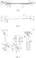
- Figs. 1-3 illustrate a disconnector with an anti-icing arrangement according to an embodiment of the present invention.
- a sealed space is formed above a moving contact to keep water and snow from covering the surface of the moving contact, such that the moving contact is not covered with an ice layer and a closing operation becomes more reliable.
- the disconnector includes a main blade moving contact 1, a main blade arm 3, a main blade static contact 5 and a main blade transmission arrangement 4 that drives the main blade arm 3 to move.
- a main blade anti-icing device includes a main blade anti-icing shield 2 and a main blade anti-icing shield transmission arrangement that drives the main blade anti-icing shield 2.
- the main blade anti-icing shield 2 can shield the main blade moving contact 1 as illustrated in Fig. 1 , so as to keep ice and snow and rainwater from covering the surface of the main blade moving contact 1.
- the main blade anti-icing shield 2 In a closed position, the main blade anti-icing shield 2 can move away from the main blade moving contact 1 as illustrated in Figs. 2-3 , such that the main blade moving contact 1 can reliably contact the main blade static contact 5.
- Fig. 4 is a stereogram of the disconnector at a closed position according to an embodiment of the present invention.
- the main blade anti-icing shield transmission arrangement can be any suitable transmission mechanisms, and preferably a structure similar to a slider crank, i.e., including a joint 6 and a transmission shaft 8.
- the transmission shaft 8 has one end connected via the joint 6 to the main blade arm 3 to move along with the main blade arm 3 and another end connected to the main blade anti-icing shield 2 to drive the main blade anti-icing shield 2 to move.
- the main blade anti-icing shield transmission arrangement can further include a main blade slide rail 7 secured on the main blade arm 3, such that the main blade anti-icing shield 2 moves along the main blade slide rail 7.
- an icing seekingng structure can also be provided on the main blade anti-icing shield 2 as illustrated in Fig. 5A to achieve reliable movement of the main blade anti-icing shield 2.
- the main blade anti-icing shield 2 can include a first part 18 and a second part 19, wherein the first part 18 has an opening greater than that of the second part 19, so as to prevent movement of the main blade anti-icing shield 2 from being blocked by the ice layer covering the main blade moving contact 1 or the main blade arm 3 during transition from the opened status to the closed status.
- the main blade anti-icing shield 2 also can be configured in a shape of an arc as illustrated in Fig. 5B .
- the interior space of the main blade anti-icing shield 2 has an admissible opening greater than an iced contour of un shielded part of the main blade arm 3 or the main blade moving contact 1, which, likewise, can prevent movement of the main blade anti-icing shield 2 from being blocked by the ice layer covering the main blade moving contact 1 or the main blade arm 3 during transition from the opened position to the closed position.
- the main blade anti-icing shield 2 of the present invention can have various appropriate shapes as long as it can reliably shield the main blade moving contact 1.
- the main blade anti-icing shield 2 has a cross section of arc, inverted U-shape, inverted V-shape, an upper half of the trapezoid or any combination thereof, which may facilitate the fall of ice and snow and rainwater therefrom.
- the main blade transmission arrangement 4 which is actuated by the mechanism, drives the main blade arm 3 to move upward as a whole, and the main blade moving contact 1 on the main blade arm will continue the closing operation to contact the main blade static contact 5 and complete the closing operation.
- the main blade anti-icing shield 2 shields outdoor rainwater and snow, and this keeps rain and water from directly covering the main blade moving contact 1.
- the slider crank structure at the anti-icing shield 2 is also driven due to driving of the main blade arm 3, such that the anti-icing shield 2 slowly moves away from the moving contact blade and the moving contact blade reliably contacts the main blade static contact 5 during the closing procedure, thereby completing the closing operation of the disconnector.
- Cooperation of the main blade anti-icing shield transmission arrangement and the main blade anti-icing shield also can be implemented by other transmission mechanisms, for example, by directly driving the main blade anti-icing shield to move through an additional transmission arrangement. It is, not limited to jointly driving them by the main blade transmission arrangement and it works as long as the anti-icing arrangement reliably shields the moving contact and concedes the contact position of the moving and static contacts during contacting.
- structure of the present invention becomes more compact and the cost gets much lower when the transmission arrangement of the disconnector per se is utilized to realize driving of the anti-icing arrangement.
- the transmission shaft is not limited to being secured on the main blade arm even if the transmission arrangement of the disconnector per se is utilized, and it also can be directly connected to and driven by the main blade transmission arrangement.
- the disconnector with an anti-icing arrangement of the present invention has advantages, such as simple and compact structure, convenient operation, reliable actions and the like.
- a sealed space is formed above the moving contact by mounting a shield on the moving contact blade to keep water and snow from covering the surface, such that the moving contact is not covered with an ice layer and the closing operation costs less labor.
- the present invention significantly improves stability and reliability of the disconnector in high and cold regions. It is not only can be suitable for a product with 10mmm icing, but also further fills the gap in products for over 20mm icing. Meanwhile, the present invention is strongly universal, can be applied into various disconnectors, and also can conveniently reform the existing disconnectors using the anti-icing arrangement assembly.
- the static contact 5 also can further include an anti-icing arrangement to better ensure reliable contact between the moving and static contacts.
- the main blade anti-icing arrangement also includes a static contact anti-icing shield 22, which can shield the main blade static contact 5 and keep ice and snow and rainwater from covering the surface of the main blade static contact 5.
- a common main blade static contact 5 is taken as an example.
- the main blade static contact 5 includes a fitting 21, an aluminum stranded wire 23, a clamp fitting 24 and a static contact copper bar 25.
- the static contact anti-icing shield 22 can be secured on any positions above the static contact copper bar 25, e.g., secured on the fitting 21 and the aluminum stranded wire 23, to shield the static contact copper bar 25, and effectively protect the static contact copper bar 25 such that the ice and snow is not accumulated thereon and causes constant growth of ice layers.
- the static contact anti-icing shield 22 of the present invention can have various appropriate shapes as long as it can reliably shield the main blade static contact 5.
- it can have a cross section of arc, inverted U-shape, inverted V-shape, an upper half of the trapezoid, or any combination thereof, which facilitates the fall of ice and snow and rainwater therefrom.
- the disconnector also can be additionally mounted with an earthing switch.
- the disconnector opens; when the disconnector is opened in place, an interlocking arrangement between the disconnector and the earthing switch is opened and the earthing switch can be operated at this time.
- An operating structure that operates the earthing switch causes the moving contact and the static contact of the earthing switch to engage, and the earthing switch additionally mounted on the disconnector is grounded at this moment, which could realize a ground protection for other devices connected to the disconnector.
- the interlocking arrangement also ensures that the disconnector itself cannot be closed.
- this additionally mounted earthing switch also faces the icing issue.
- Fig. 7 illustrates a structure of an earthing switch additionally mounted on the disconnector, including an earthing blade static contact 9, an insulator 10, an earthing blade 13, an earthing blade moving contact 12 and a base 11.
- the earthing switch also can further include an earthing blade anti-icing shield 14 and an earthing blade anti-icing shield transmission arrangement for driving the earthing blade anti-icing shield 14.
- the earthing blade anti-icing shield 14 shields the earthing blade moving contact 12, to keep ice and snow and rainwater from covering the surface of the earthing blade moving contact 12.
- the earthing blade anti-icing shield 14 moves away from the earthing blade moving contact 12 , such that the earthing blade moving contact 12 can contact the earthing blade static contact 9.
- Fig. 8 is a front view of the earthing switch of the disconnector at the opening position according to embodiments of the present invention.
- the earthing blade anti-icing shield transmission arrangement can be implemented by any suitable transmission mechanisms, and preferably a structure similar to a slider crank including a crank 17 and a connecting rod 15. One end 13 of the earthing blade is connected on the base 11; the crank 17 is connected between the base 11 and the earthing blade 13; and the connecting rod 15 has one end secured to the earthing blade 13 and another end connected to the earthing blade anti-icing shield 14.
- the earthing blade anti-icing shield transmission device further can include an earthing blade slide rail 16 secured on the earthing blade 13, such that the earthing blade anti-icing shield 14 moves along the earthing blade slide rail 16.
- the earthing blade anti-icing shield 14 In order to avoid block from other positions (e.g., block from the ice layer covering the earthing blade 13) while the earthing blade anti-icing shield 14 is moving away from the earthing blade moving contact 12, which affects the earthing blade anti-icing shield 14 to smoothly concede the contact position of the moving and static contacts, and in order to better implement reliable operation of the earthing switch, the earthing blade anti-icing shield 14 also can have a structure of the earthing blade anti-icing shield as illustrated in Fig. 5A , i.e., an icing seekingng structure being provided on the earthing blade anti-icing shield 14 to achieve reliable movement of the earthing blade anti-icing shield 14.
- the earthing blade anti-icing shield 14 can include a front segment and a rear segment, and the front segment has an opening greater than that of the rear segment, so as to prevent movement of the earthing blade anti-icing shield 14 from being blocked by the ice layer covering the earthing blade moving contact 12 or the earthing blade 13 during transition from the opened position to the closed position.
- the earthing blade anti-icing shield 14 also can be configured in a shape of an arc as illustrated in Fig. 5B .
- the interior space of the earthing blade anti-icing shield 14 have an admissible opening greater than an iced contour of the unshielded part of the earthing blade 13 or the earthing blade moving contact 12, which, likewise, can prevent movement of the earthing blade anti-icing shield 14 from being blocked by the ice layer covering the earthing blade moving contact 12 or the earthing blade 13 during transition from the opened position to the closed position.
- the earthing blade anti-icing shield 14 of the present invention can have any appropriate shape as long as it can reliably shield the earthing blade moving contact 12.
- the earthing blade anti-icing shield 14 has a cross section of arc, inverted U-shape, inverted V-shape, an upper half of the trapezoid or any combination thereof, which facilitates fall of ice and snow and rainwater.
- the earthing switch is a slider crank structure and for facilitating explanation, the crank 17 is indicated by AB, the connecting rod 15 is indicated by EF, one end of the earthing blade is indicated by CD, the moving contact is indicated by FG and the anti-icing shield is indicated by FH.
- the shield indicated by FH can shield the moving contact indicated by FG from ice or rainwater in the opened operation, so as to protect the moving contact.
- the anti-icing shield FH is covered with ice of a certain thickness after icing, and at this time, the earthing blade is driven by the operating mechanism to close.
- the earthing blade As illustrated in Fig. 10 , the earthing blade, at a middle position, is driven by the operating mechanism to move towards the closing position. Due to operations of the slider crank structure, the F point generates relative movement on CG and CF is shortened, which drags the shield indicated by FH to move and exposes the position of the moving contact indicated by FG to the outside.
- the anti-icing shield indicated by FH exposes the moving contact indicated by FG, such that the moving contact indicated by FG can contact the earthing blade static contact.
- the overall movement can be similar to a movement that the crank AB rotates as a drive crank such that the slider F slidably moves along the DG rod.
- Cooperation of the earthing blade anti-icing shield transmission arrangement and the earthing blade anti-icing shield also can be implemented by any other transmission mechanism, for example, by directly driving the earthing blade anti-icing shield to move through an additional transmission arrangement. It is not limited to be jointly driving them by the earthing blade, and it works as long as the anti-icing arrangement reliably shields the moving contact and concedes a contact point of the moving and static contacts during contacting.
- the transmission shaft is not limited to the slider crank structure even if the transmission arrangement of the earthing switch per se is utilized, and it also can adopt, for example, any other connection that can convert rotation and movement with each other.
Landscapes
- Physics & Mathematics (AREA)
- Electromagnetism (AREA)
- Gas-Insulated Switchgears (AREA)
- Slide Switches (AREA)
Abstract
Description
- The present invention belongs to the field of electrical power devices and relates to a disconnector with an anti-icing arrangement, and more particularly, to a disconnector with an earthing switch and an anti-icing arrangement.
- A disconnector is a switching device that could provide, at an opening position, an insulation distance between contacts conforming to specified requirements and a distinct disconnection sign and could withstand, at a closing position, currents under a normal circuit condition and currents under an abnormal condition (e.g., short circuit) within a specified time. The disconnector is an important switching device in an electrical power system and its primary function is to ensure safety during maintenance of high-voltage electrical devices and apparatuses and to isolate the voltage.
- In high latitude areas, such as northern cold regions, the temperature is quite low in winter and the operating environment is harsh. The ice and snow that cover the outdoor disconnector for a long time will impact reliability of opening and closing actions of the switch, such that contacts of the disconnector are separated by ice and cannot be completely conducted, which disables operations and threatens operation of electrical power systems and safety of power grids.
- To solve the ice coating issues, the existing disconnector, while closing, usually enables the contact to have ice-breaking functionality. For example, when the moving contact and the static contact of the disconnector are being closed, a clamping and sliding procedure occurs to break the ice layer. However, this method for breaking the icing with an increased clamping force of the contact can only break the icing of a certain thickness, and cause wear of contacts, increase in operating force and a higher rigidity requirement. Besides, it also increases output torque of mechanisms and has a defect of higher costs. In the northern cold regions, the outdoor disconnector might be covered with an ice layer of up to 20mm or more, whereas the existing disconnector can hardly ensure normal operations even in an environment with icing of 10mm. Thus, it might impact operation of electrical power devices in a cold and freezing environment and cannot ensure safe and stable operations of the entire electrical system. The high-voltage disconnector even cannot open or close when the icing is heavy.
- In order to solve this problem, the prior art also provides a light energy ice-breaking auxiliary arrangement. That is, solar energy is gathered and incident to a light-to-heat converter to convert light energy to thermal energy and achieve a purpose of breaking ice by heating. However, this light energy ice-breaking auxiliary arrangement and the heat ice-breaking auxiliary arrangements based on other principles have complex structure and lower reliability, and thus cannot meet needs of actual operations.
- To satisfy the usage requirements of disconnector in northern cold regions, an outdoor disconnector with anti-icing function is in urgent need in the prior art, which still can perform reliable mechanical operations when the ice layer reaches a thickness of 20mm at most.
- The purpose of the present invention is to solve the problem existing in the prior art and provide a disconnector with an anti-icing arrangement, such that the opening and closing actions of the outdoor disconnector can be performed reliably, thereby ensuring normal operation of the disconnector in high and cold regions.
- The solution of the present invention provides a disconnector with an anti-icing arrangement. The disconnector comprises a main blade moving contact, a main blade arm, a main blade static contact and a main blade transmission arrangement that drives the main blade arm to move. The disconnector further comprises a main blade anti-icing arrangement that includes a main blade anti-icing shield and a main blade anti-icing shield transmission arrangement, wherein the main blade anti-icing shield transmission arrangement drives the main blade anti-icing shield such that the main blade anti-icing shield shields the main blade moving contact in an opening operation to keep ice and snow and rainwater from covering a surface of the main blade moving contact and moves away from the main blade moving contact in a closing operation, to enable the main blade moving contact to be contacted with the static contact.
- According to a preferred embodiment of the present invention, the main blade anti-icing transmission arrangement comprises a joint and a transmission shaft, one end of the transmission shaft being connected via the joint to the main blade arm for moving along with the main blade arm, and another end of the transmission shaft being connected to the main blade anti-icing shield.
- According to a preferred embodiment of the present invention, the main blade anti-icing shield transmission arrangement comprises a main blade slide rail secured on the main blade arm for enabling the main blade anti-icing shield to move along the main blade slide rail.
- According to a preferred embodiment of the present invention, the main blade anti-icing shield includes a first part and a second part. The first part has an opening greater than an opening of the second part, to prevent movement of the main blade anti-icing shield from being blocked by an ice layer covering the main blade moving contact or the main blade arm during transition from an opened position to a closed position.
- According to a preferred embodiment of the present invention, the main blade anti-icing shield has a cross section of arc, inverted U-shape, inverted V-shape, an upper half of a trapezoid or any combination thereof, for reliably shielding the main blade moving contact and facilitating fall of ice and snow and rainwater therefrom.
- According to a preferred embodiment of the present invention, the main blade anti-icing arrangement further comprises a static contact anti-icing shield for shielding the main blade static contact and keeping ice and snow and rainwater from covering a surface of the main blade static contact.
- According to a preferred embodiment of the present invention, the main blade static contact comprises a fitting, an aluminum stranded wire, a clamp fitting and a static contact copper bar, the static contact anti-icing shield being used for shielding the static contact copper bar.
- According to a preferred embodiment of the present invention, the static contact anti-icing shield has a cross section of arc, inverted U-shape, inverted V-shape, an upper half of a trapezoid or any combination thereof, for reliably shielding the main blade static contact and facilitating fall of ice and snow and rainwater therefrom.
- According to a preferred embodiment of the present invention, the disconnector further comprises a mounted earthing switch including an earthing switch static contact, an insulator, an earthing blade, a moving contact and a base. The earthing switch further comprises an earthing switch anti-icing arrangement having an earthing switch anti-icing shield and an earthing switch anti-icing shield transmission arrangement, wherein the earthing switch anti-icing shield transmission arrangement drives the earthing switch anti-icing shield so that the earthing switch anti-icing shield shields the earthing switch moving contact in the opened position to keep ice and snow and rainwater from covering a surface of the earthing switch moving contact, and moves away from the earthing moving contact in the closing operation to enable the earthing switch moving contact to be contacted with the earthing switch static contact.
- According to a preferred embodiment of the present invention, the earthing switch anti-icing shield transmission arrangement comprises a crank and a connecting rod, one end of the earthing switch being connected to the base, the crank being connected between the base and the earthing switch, one end of the connecting rod being secured on the earthing switch and another end of the connecting rod being connected to the earthing switch anti-icing shield.
- According to a preferred embodiment of the present invention, the earthing blade anti-icing shield transmission arrangement comprises an earthing blade slide rail secured on the earthing blade for enabling the earthing blade anti-icing shield to move along the earthing blade slide rail.
- According to a preferred embodiment of the present invention, the earthing switch anti-icing shield comprises a front segment and a rear segment, and the front segment has an opening greater than that of the rear segment to prevent movement of the earthing switch anti-icing shield from being blocked by an ice layer covering the earthing switch moving contact or the earthing switch during transition from the opened position to the closed position.
- According to a preferred embodiment of the present invention, the earthing switch anti-icing shield has a cross section of arc, inverted U-shape, inverted V-shape, an upper half of a trapezoid or any combination thereof, for reliably shielding the earthing blade moving contact and facilitating fall of ice and snow and rainwater therefrom.
- The isolated switch with an anti-icing arrangement of the present invention has advantages such as simple and compact structure, convenient operation, reliable actions and the like. A sealed space is formed above the moving contact by mounting a shield on the moving contact blade to keep water and snow from covering the surface, which causes the moving contact being not covered by an ice layer and closing operations requiring less labor. Since the present invention further implements driving of the anti-icing arrangement by smartly using the transmission arrangement of the disconnector per se, the disconnector with an anti-icing device of the present invention has a rather compact structure. Besides, the anti-icing arrangement of the present invention can flexibly employ various shapes and dimensions without changing the working principle, thereby adapting to different disconnector with a strong universality. In addition, the anti-icing arrangement of the present disclosure can be conveniently mounted on the existing disconnector as a component and achieve a technical effect of anti-icing without replacing the existing disconnector with a new disconnector with an anti-icing arrangement, thereby substantially saving the cost of reforming the existing device.
- To sum up, the technical solution of the present invention significantly improves stability and reliability of the disconnector in high and cold regions. The present invention not only can be suitable for products with 10mmm icing, but also further fills a gap in products for over 20mm icing. Meanwhile, the present invention is strongly universal, can be applied into various disconnectors, and also can conveniently reform the existing disconnectors using the solution of the present disclosure.
- The present invention will be further described hereinafter with reference to drawings and embodiments.
- The following drawings are given to better illustrate embodiments of the present invention. It is to be understood that the drawings only illustrate preferred embodiments of the present invention in an exemplary manner and the drawings should not be interpreted as limitations to the present invention, wherein:
-
Fig. 1 is an overall schematic diagram of a disconnector at an opened position according to a preferred embodiment of the present invention; -
Fig. 2 is an overall schematic diagram of a disconnector at a closed position according to a preferred embodiment of the present invention; -
Fig. 3 is a front view of a disconnector at a closed position according to a preferred embodiment of the present invention; -
Fig. 4 is a stereogram of a disconnector at a closed position according to a preferred embodiment of the present invention; -
Fig. 5A is a stereogram of an anti-icing shield of a disconnector or an earthing switch according to a preferred embodiment of the present invention;Fig. 5B is a stereogram of an anti-icing shield of a disconnector or an earthing switch according to a further preferred embodiment of the present invention; -
Fig. 6 is a stereogram of a main blade static contact of a disconnector according to a preferred embodiment of the present invention; -
Fig. 7 is an overall structure diagram of an earthing switch of a disconnector according to a preferred embodiment of the present invention; -
Fig. 8 is a front view of an earthing switch of a disconnector according to a preferred embodiment of the present invention; -
Fig. 9 is a schematic diagram of an earthing switch of a disconnector at an opening position according to a preferred embodiment of the present invention; -
Fig. 10 is a schematic diagram of an earthing switch of a disconnector at a middle position according to a preferred embodiment of the present invention; and -
Fig. 11 is a schematic diagram of an earthing switch of a disconnector at a closed position according to a preferred embodiment of the present invention. - Throughout the description and drawings, same reference signs indicate the same or similar features or elements.
- Hereinafter, example solutions of the present invention will be explained in details with reference to the following description and the drawings. The drawings of the present application are not made exactly according to actual dimensions of the solutions according to embodiments, and changes regarding dimensions should not be interpreted as limitations to the present invention. "As illustrated in Fig...." or the like used hereinbelow refers to description of a particular technical feature with reference to a certain drawing. However, it should not be understood that this particular technical feature or its equivalent is included in this drawing only.
- In the following description, some direction terms such as "left," "right," "up," "down," "front" and "back" and the like only denote a direction indicated with reference to the drawings. However, when the application scenario varies, the directions represented by the direction terms will change accordingly. Terms, such as "first," "second" and the like describe a plurality of components but do not mean any sequence among the components and these terms only aim to distinguish one component from another.
-
Figs. 1-3 illustrate a disconnector with an anti-icing arrangement according to an embodiment of the present invention. A sealed space is formed above a moving contact to keep water and snow from covering the surface of the moving contact, such that the moving contact is not covered with an ice layer and a closing operation becomes more reliable. - The disconnector includes a main
blade moving contact 1, amain blade arm 3, a main bladestatic contact 5 and a mainblade transmission arrangement 4 that drives themain blade arm 3 to move. A main blade anti-icing device includes a main bladeanti-icing shield 2 and a main blade anti-icing shield transmission arrangement that drives the main bladeanti-icing shield 2. In an opened position, the main bladeanti-icing shield 2 can shield the mainblade moving contact 1 as illustrated inFig. 1 , so as to keep ice and snow and rainwater from covering the surface of the mainblade moving contact 1. In a closed position, the main bladeanti-icing shield 2 can move away from the mainblade moving contact 1 as illustrated inFigs. 2-3 , such that the mainblade moving contact 1 can reliably contact the main bladestatic contact 5. - The anti-icing arrangement will be described in details with reference to
Figs. 4-5 . It should be understood that all of descriptions are only given as examples and those skilled in the art, after review of contents of the present invention, can make various changes or modifications to the contents introduced herein. For the sake of simplicity, the text will not enumerate all possible changes, modifications or equivalents, but these changes, modifications or equivalents should certainly be included within disclosure and protection scope of the present invention. -
Fig. 4 is a stereogram of the disconnector at a closed position according to an embodiment of the present invention. The main blade anti-icing shield transmission arrangement can be any suitable transmission mechanisms, and preferably a structure similar to a slider crank, i.e., including a joint 6 and atransmission shaft 8. Thetransmission shaft 8 has one end connected via the joint 6 to themain blade arm 3 to move along with themain blade arm 3 and another end connected to the main bladeanti-icing shield 2 to drive the main bladeanti-icing shield 2 to move. To further regulate movement track of the main bladeanti-icing shield 2, the main blade anti-icing shield transmission arrangement can further include a mainblade slide rail 7 secured on themain blade arm 3, such that the main bladeanti-icing shield 2 moves along the mainblade slide rail 7. - In order to avoid block from other positions (for example, block from the ice layer covering the main blade arm 3) while the main blade
anti-icing shield 2 is moving away from the mainblade moving contact 1, which affects the main bladeanti-icing shield 2 to smoothly concede the contact position of the moving and static contacts, and in order to better implement reliable operation of the disconnector, an icing conceding structure can also be provided on the main bladeanti-icing shield 2 as illustrated inFig. 5A to achieve reliable movement of the main bladeanti-icing shield 2. The main bladeanti-icing shield 2 can include afirst part 18 and asecond part 19, wherein thefirst part 18 has an opening greater than that of thesecond part 19, so as to prevent movement of the main bladeanti-icing shield 2 from being blocked by the ice layer covering the mainblade moving contact 1 or themain blade arm 3 during transition from the opened status to the closed status. The main bladeanti-icing shield 2 also can be configured in a shape of an arc as illustrated inFig. 5B . Thus, the interior space of the main bladeanti-icing shield 2 has an admissible opening greater than an iced contour of un shielded part of themain blade arm 3 or the mainblade moving contact 1, which, likewise, can prevent movement of the main bladeanti-icing shield 2 from being blocked by the ice layer covering the mainblade moving contact 1 or themain blade arm 3 during transition from the opened position to the closed position. - The main blade
anti-icing shield 2 of the present invention can have various appropriate shapes as long as it can reliably shield the mainblade moving contact 1. Preferably, the main bladeanti-icing shield 2 has a cross section of arc, inverted U-shape, inverted V-shape, an upper half of the trapezoid or any combination thereof, which may facilitate the fall of ice and snow and rainwater therefrom. - To better understand the present invention, an operation procedure of the disconnector with an anti-icing arrangement of the present invention will be briefly described below with reference to
Figs. 1-5 . - When a closing operation is performed at the opening position, the main
blade transmission arrangement 4, which is actuated by the mechanism, drives themain blade arm 3 to move upward as a whole, and the mainblade moving contact 1 on the main blade arm will continue the closing operation to contact the main bladestatic contact 5 and complete the closing operation. In the opened position, the main bladeanti-icing shield 2 shields outdoor rainwater and snow, and this keeps rain and water from directly covering the mainblade moving contact 1. When the closing operation is being performed, the slider crank structure at theanti-icing shield 2 is also driven due to driving of themain blade arm 3, such that theanti-icing shield 2 slowly moves away from the moving contact blade and the moving contact blade reliably contacts the main bladestatic contact 5 during the closing procedure, thereby completing the closing operation of the disconnector. - Cooperation of the main blade anti-icing shield transmission arrangement and the main blade anti-icing shield also can be implemented by other transmission mechanisms, for example, by directly driving the main blade anti-icing shield to move through an additional transmission arrangement. It is, not limited to jointly driving them by the main blade transmission arrangement and it works as long as the anti-icing arrangement reliably shields the moving contact and concedes the contact position of the moving and static contacts during contacting. However, those skilled in the art can understand that structure of the present invention becomes more compact and the cost gets much lower when the transmission arrangement of the disconnector per se is utilized to realize driving of the anti-icing arrangement. The transmission shaft is not limited to being secured on the main blade arm even if the transmission arrangement of the disconnector per se is utilized, and it also can be directly connected to and driven by the main blade transmission arrangement.
- The disconnector with an anti-icing arrangement of the present invention has advantages, such as simple and compact structure, convenient operation, reliable actions and the like. A sealed space is formed above the moving contact by mounting a shield on the moving contact blade to keep water and snow from covering the surface, such that the moving contact is not covered with an ice layer and the closing operation costs less labor. The present invention significantly improves stability and reliability of the disconnector in high and cold regions. It is not only can be suitable for a product with 10mmm icing, but also further fills the gap in products for over 20mm icing. Meanwhile, the present invention is strongly universal, can be applied into various disconnectors, and also can conveniently reform the existing disconnectors using the anti-icing arrangement assembly.
- Furthermore, the
static contact 5 also can further include an anti-icing arrangement to better ensure reliable contact between the moving and static contacts. As illustrated inFig. 6 , the main blade anti-icing arrangement also includes a static contactanti-icing shield 22, which can shield the main bladestatic contact 5 and keep ice and snow and rainwater from covering the surface of the main bladestatic contact 5. - In order to better understand the present invention, a common main blade
static contact 5 is taken as an example. The main bladestatic contact 5 includes a fitting 21, an aluminum strandedwire 23, a clamp fitting 24 and a staticcontact copper bar 25. As illustrated inFig. 6 . The static contactanti-icing shield 22 can be secured on any positions above the staticcontact copper bar 25, e.g., secured on the fitting 21 and the aluminum strandedwire 23, to shield the staticcontact copper bar 25, and effectively protect the staticcontact copper bar 25 such that the ice and snow is not accumulated thereon and causes constant growth of ice layers. - The static contact
anti-icing shield 22 of the present invention can have various appropriate shapes as long as it can reliably shield the main bladestatic contact 5. Preferably, it can have a cross section of arc, inverted U-shape, inverted V-shape, an upper half of the trapezoid, or any combination thereof, which facilitates the fall of ice and snow and rainwater therefrom. - The disconnector also can be additionally mounted with an earthing switch. When it is required to operate the disconnector, the disconnector opens; when the disconnector is opened in place, an interlocking arrangement between the disconnector and the earthing switch is opened and the earthing switch can be operated at this time. An operating structure that operates the earthing switch causes the moving contact and the static contact of the earthing switch to engage, and the earthing switch additionally mounted on the disconnector is grounded at this moment, which could realize a ground protection for other devices connected to the disconnector. Meanwhile, the interlocking arrangement also ensures that the disconnector itself cannot be closed. However, this additionally mounted earthing switch also faces the icing issue.
-
Fig. 7 illustrates a structure of an earthing switch additionally mounted on the disconnector, including an earthing bladestatic contact 9, aninsulator 10, an earthingblade 13, an earthingblade moving contact 12 and abase 11. To reliably implement grounding, the earthing switch also can further include an earthing bladeanti-icing shield 14 and an earthing blade anti-icing shield transmission arrangement for driving the earthing bladeanti-icing shield 14. In the opened status, the earthing bladeanti-icing shield 14 shields the earthingblade moving contact 12, to keep ice and snow and rainwater from covering the surface of the earthingblade moving contact 12. In the closed position, the earthing bladeanti-icing shield 14 moves away from the earthingblade moving contact 12 , such that the earthingblade moving contact 12 can contact the earthing bladestatic contact 9. -
Fig. 8 is a front view of the earthing switch of the disconnector at the opening position according to embodiments of the present invention. The earthing blade anti-icing shield transmission arrangement can be implemented by any suitable transmission mechanisms, and preferably a structure similar to a slider crank including a crank 17 and a connectingrod 15. Oneend 13 of the earthing blade is connected on thebase 11; thecrank 17 is connected between the base 11 and the earthingblade 13; and the connectingrod 15 has one end secured to the earthingblade 13 and another end connected to the earthing bladeanti-icing shield 14. To further regulate movement track of the earthing bladeanti-icing shield 14, the earthing blade anti-icing shield transmission device further can include an earthingblade slide rail 16 secured on the earthingblade 13, such that the earthing bladeanti-icing shield 14 moves along the earthingblade slide rail 16. - In order to avoid block from other positions (e.g., block from the ice layer covering the earthing blade 13) while the earthing blade
anti-icing shield 14 is moving away from the earthingblade moving contact 12, which affects the earthing bladeanti-icing shield 14 to smoothly concede the contact position of the moving and static contacts, and in order to better implement reliable operation of the earthing switch, the earthing bladeanti-icing shield 14 also can have a structure of the earthing blade anti-icing shield as illustrated inFig. 5A , i.e., an icing conceding structure being provided on the earthing bladeanti-icing shield 14 to achieve reliable movement of the earthing bladeanti-icing shield 14. The earthing bladeanti-icing shield 14 can include a front segment and a rear segment, and the front segment has an opening greater than that of the rear segment, so as to prevent movement of the earthing bladeanti-icing shield 14 from being blocked by the ice layer covering the earthingblade moving contact 12 or the earthingblade 13 during transition from the opened position to the closed position. The earthing bladeanti-icing shield 14 also can be configured in a shape of an arc as illustrated inFig. 5B . Thus, the interior space of the earthing bladeanti-icing shield 14 have an admissible opening greater than an iced contour of the unshielded part of the earthingblade 13 or the earthingblade moving contact 12, which, likewise, can prevent movement of the earthing bladeanti-icing shield 14 from being blocked by the ice layer covering the earthingblade moving contact 12 or the earthingblade 13 during transition from the opened position to the closed position. - The earthing blade
anti-icing shield 14 of the present invention can have any appropriate shape as long as it can reliably shield the earthingblade moving contact 12. Preferably, the earthing bladeanti-icing shield 14 has a cross section of arc, inverted U-shape, inverted V-shape, an upper half of the trapezoid or any combination thereof, which facilitates fall of ice and snow and rainwater. - To better understand the present invention, operating procedures of the earthing switch of the disconnector having an anti-icing arrangement of the present invention will be briefly described below with reference to
Figs. 8-11 . In fact, the earthing switch is a slider crank structure and for facilitating explanation, thecrank 17 is indicated by AB, the connectingrod 15 is indicated by EF, one end of the earthing blade is indicated by CD, the moving contact is indicated by FG and the anti-icing shield is indicated by FH. - As illustrated in
Fig. 9 , the shield indicated by FH can shield the moving contact indicated by FG from ice or rainwater in the opened operation, so as to protect the moving contact. The anti-icing shield FH is covered with ice of a certain thickness after icing, and at this time, the earthing blade is driven by the operating mechanism to close. - As illustrated in
Fig. 10 , the earthing blade, at a middle position, is driven by the operating mechanism to move towards the closing position. Due to operations of the slider crank structure, the F point generates relative movement on CG and CF is shortened, which drags the shield indicated by FH to move and exposes the position of the moving contact indicated by FG to the outside. - As illustrated in
Fig. 11 , when the closing operations continue to reach the closing position, the anti-icing shield indicated by FH exposes the moving contact indicated by FG, such that the moving contact indicated by FG can contact the earthing blade static contact. - Thus, the overall movement can be similar to a movement that the crank AB rotates as a drive crank such that the slider F slidably moves along the DG rod.
- Cooperation of the earthing blade anti-icing shield transmission arrangement and the earthing blade anti-icing shield also can be implemented by any other transmission mechanism, for example, by directly driving the earthing blade anti-icing shield to move through an additional transmission arrangement. It is not limited to be jointly driving them by the earthing blade, and it works as long as the anti-icing arrangement reliably shields the moving contact and concedes a contact point of the moving and static contacts during contacting. However, those skilled in the art can understand that structure of the present invention becomes more compact and the cost gets lower when the transmission arrangement of the earthing switch per se is utilized to realize driving of the anti-icing arrangement. The transmission shaft is not limited to the slider crank structure even if the transmission arrangement of the earthing switch per se is utilized, and it also can adopt, for example, any other connection that can convert rotation and movement with each other.
- The above technical solutions can be combined according to requirements to achieve the optimal technical effects.
- The above description is just made for principles and preferred embodiments of the present invention. It should be noted that although preferred embodiments and drawings of the present invention have been disclosed for the purpose of explaining the present invention, those skilled in the art can make various substitutions, alterations and modifications without deviating from the spirit and the scope of the present invention and the attached claims. Several other variations based on the principle of the present invention also should be considered as being fallen within the protection scope of the present invention. Therefore, the present invention should not be limited to contents disclosed by preferred embodiments and drawings, and the protection scope of the present invention is defined by the attached claims.
Claims (13)
- A disconnector with an anti-icing arrangement, comprising a main blade moving contact (1), a main blade arm (3), a main blade static contact (5) and a main blade transmission arrangement (4) that drives the main blade arm (3) to move, characterized by further comprising a main blade anti-icing arrangement that includes a main blade anti-icing shield (2) and a main blade anti-icing shield transmission arrangement, wherein
the main blade anti-icing shield transmission arrangement is adapted for driving the main blade anti-icing shield (2), such that the main blade anti-icing shield (2) shields the main blade moving contact (1) in an opening operation to keep ice and snow and rainwater from covering a surface of the main blade moving contact (1), and moves away from the main blade moving contact (1) in a closing operation to enable the main blade moving contact (1) to be contacted with the main blade static contact (5). - The disconnector of claim 1, characterized in that: the main blade anti-icing transmission arrangement comprises a joint (6) and a transmission shaft (8), one end of the transmission shaft (8) being connected via the joint (6) to the main blade arm (3) for moving along with the main blade arm (3), and another end of the transmission shaft (8) being connected to the main blade anti-icing shield (2).
- The disconnector of claim 1, characterized in that: the main blade anti-icing shield transmission arrangement comprises a main blade slide rail (7) secured on the main blade moving contact (1) for enabling the main blade anti-icing shield (2) to move along the main blade slide rail (7).
- The disconnector of claim 1, characterized in that: the main blade anti-icing shield (2) comprises a first part (18) and a second part (19) and the first part (18) has an opening greater than that of the second part (19) to prevent movement of the main blade anti-icing shield (2) from being blocked by an ice layer covering the main blade moving contact (1) or the main blade arm (3) during transition from the opened position to the closed position.
- The disconnector of claim 1, characterized in that: the main blade anti-icing shield (2) has a cross section of arc, inverted U-shape, inverted V-shape, an upper half of a trapezoid or any combination thereof, for reliably shielding the main blade moving contact (1) and facilitating fall of ice and snow and rainwater therefrom.
- The disconnector of claim 1, characterized in that: the main blade anti-icing arrangement further comprises a static contact anti-icing shield (22) for shielding the main blade static contact (5) and keeping ice and snow and rainwater from covering a surface of the main blade static contact (5).
- The disconnector of claim 6, characterized in that: the main blade static contact (5) comprises a fitting (21), an aluminum stranded wire (23), a clamp fitting (24) and a static contact copper bar (25), the static contact anti-icing shield (22) adapted for shielding the static contact copper bar (25).
- The disconnector of claim 6, characterized in that: the static contact anti-icing shield (22) has a cross section of arc, inverted U-shape, inverted V-shape, an upper half of a trapezoid or any combination thereof, for reliably shielding the main blade static contact (5) and facilitating fall of ice and snow and rainwater therefrom.
- The disconnector of any of claims 1-8, characterized in that: the disconnector further comprises an additionally mounted earthing switch including an earthing blade static contact (9), an insulator (10), an earthing blade (13), an earthing blade moving contact (12) and a base (11), and the earthing switch further comprises an earthing blade anti-icing arrangement comprises an earthing blade anti-icing shield (14) and an earthing blade anti-icing shield transmission arrangement, wherein
the earthing blade anti-icing shield transmission arrangement is adapted for driving the earthing blade anti-icing shield (14) such that the earthing blade anti-icing shield (14) shields the earthing blade moving contact (12) in the opened position to keep ice and snow and rainwater from covering a surface of the earthing blade moving contact (12), and moves away from the earthing moving contact (12) in the closed position to enable the earthing blade moving contact (12) to be contacted with the earthing blade static contact (9). - The disconnector of claim 9, characterized in that: the earthing blade anti-icing shield transmission arrangement comprises a crank (17) and a connecting rod (15), one end (13) of the earthing blade being connected to the base (11), the crank (17) being connected between the base (11) and the earthing blade (13), one end of the connecting rod (15) being secured on the earthing blade (13) and another end being connected to the earthing blade anti-icing shield (14).
- The disconnector of claim 9, characterized in that: the earthing blade anti-icing shield transmission arrangement comprises an earthing blade slide rail (16) secured on the earthing blade (13) for enabling the earthing blade anti-icing shield (14) to move along the earthing blade slide rail (16).
- The disconnector of claim 9, characterized in that: the earthing blade anti-icing shield (14) comprises a front segment and a rear segment, the front segment has an opening greater than that of the rear segment to avoid movement of the earthing blade anti-icing shield (14) from being blocked by an ice layer covering the earthing blade moving contact (12) or the earthing blade (13) during transition from the opened position to the closed position.
- The disconnector of claim 9, characterized in that: the earthing blade anti-icing shield (14) has a cross section of arc, inverted U-shape, inverted V-shape, an upper half of a trapezoid or any combination thereof, for reliably shielding the earthing blade moving contact (12) and facilitating fall of ice and snow and rainwater therefrom.
Applications Claiming Priority (1)
| Application Number | Priority Date | Filing Date | Title |
|---|---|---|---|
| PCT/CN2016/074643 WO2017143582A1 (en) | 2016-02-26 | 2016-02-26 | Disconnecting switch having anti-icing device |
Publications (3)
| Publication Number | Publication Date |
|---|---|
| EP3422380A1 true EP3422380A1 (en) | 2019-01-02 |
| EP3422380A4 EP3422380A4 (en) | 2019-10-16 |
| EP3422380B1 EP3422380B1 (en) | 2020-10-28 |
Family
ID=59684955
Family Applications (1)
| Application Number | Title | Priority Date | Filing Date |
|---|---|---|---|
| EP16891036.2A Active EP3422380B1 (en) | 2016-02-26 | 2016-02-26 | Disconnecting switch having anti-icing device |
Country Status (5)
| Country | Link |
|---|---|
| US (1) | US10622166B2 (en) |
| EP (1) | EP3422380B1 (en) |
| CN (1) | CN108604511B (en) |
| DK (1) | DK3422380T3 (en) |
| WO (1) | WO2017143582A1 (en) |
Families Citing this family (7)
| Publication number | Priority date | Publication date | Assignee | Title |
|---|---|---|---|---|
| CN111354593B (en) * | 2018-12-24 | 2021-12-03 | 河南平高电气股份有限公司 | Telescopic outdoor high-voltage isolating switch and lower conductive tube assembly thereof |
| CN110942934B (en) * | 2019-12-16 | 2025-07-01 | 上海大华电器设备有限公司 | An operating mechanism based on double-throw four-pole switch |
| CN113270289B (en) * | 2021-05-21 | 2022-06-07 | 贵州电网有限责任公司 | Isolating switch contact congeals processing apparatus based on multi-direction injection |
| CN118039402B (en) * | 2024-03-08 | 2025-02-11 | 河北华能源电力设备有限公司 | A conductive contact rod structure for disconnector and working method thereof |
| CN118380279B (en) * | 2024-06-24 | 2024-09-17 | 江苏省如高高压电器有限公司 | Anti-icing scissor type isolating switch |
| CN118919326B (en) * | 2024-09-10 | 2025-04-04 | 西安金叶电力科技有限公司 | A self-melting double-position isolating switch |
| CN119601413B (en) * | 2024-12-05 | 2025-10-24 | 江苏省如高高压电器有限公司 | Isolating switch anti-icing device |
Family Cites Families (16)
| Publication number | Priority date | Publication date | Assignee | Title |
|---|---|---|---|---|
| DE1665881B2 (en) * | 1967-02-24 | 1974-03-21 | Siemens Ag, 1000 Berlin U. 8000 Muenchen | Electrical switch for use in areas where there is a risk of icing |
| US3530265A (en) * | 1969-05-28 | 1970-09-22 | Ite Imperial Corp | Shielding for vertical break switches of high voltage rating |
| US4296284A (en) * | 1979-12-26 | 1981-10-20 | Siemens-Allis, Inc. | Flexible shield for high voltage disconnect switch |
| US4564731A (en) * | 1982-03-17 | 1986-01-14 | Ruhrtal-Elektrizitatsgesellschaft Hartig Gmbh & Co. | Scissor-type disconnect switch with contact elements having wear-resistant armatures |
| FR2691009B1 (en) * | 1992-05-11 | 1997-04-04 | Gec Alsthom Engergie Inc | SECTIONER WITH VERTICAL OPENING AND OSCILLATING COLUMN. |
| RU2234159C1 (en) * | 2003-02-03 | 2004-08-10 | Закрытое акционерное общество "Завод электротехнического оборудования" | Disconnecting switch |
| US7223928B2 (en) * | 2004-12-20 | 2007-05-29 | S&C Electric Canada Ltd. | Switch with improved protection from ice conditions |
| CN2819422Y (en) * | 2005-09-26 | 2006-09-20 | 王光顺 | Switching dustproofing contact of super-voltage isolated switch |
| CN2859790Y (en) * | 2006-01-10 | 2007-01-17 | 王光顺 | Cut-in type super high voltage insulating switch contact with resistance |
| CN201868307U (en) * | 2010-12-10 | 2011-06-15 | 河南省电力公司三门峡供电公司 | Rainproof cover of moving contact of isolating switch |
| CN202650941U (en) * | 2012-05-31 | 2013-01-02 | 山东泰开隔离开关有限公司 | High-voltage direct current isolating switch capable of moving vertically and horizontally |
| FR3003992B1 (en) * | 2013-03-28 | 2017-03-03 | Alstom Technology Ltd | AUTO LIGHTWEIGHT DEPLACANT DRIVER |
| CN203617205U (en) * | 2013-12-04 | 2014-05-28 | 正泰电气股份有限公司 | In-line disconnecting switch structure with special positional arrangement of grounding switch |
| CN203674058U (en) * | 2014-01-21 | 2014-06-25 | 河北奥斯特电力设备有限公司 | GW4 high-voltage isolation switch |
| CN204215909U (en) * | 2014-10-27 | 2015-03-18 | 湖南长高高压开关集团股份公司 | The switching-on mechanism of high voltage isolator |
| CN104319157B (en) * | 2014-11-20 | 2016-08-24 | 河南平高电气股份有限公司 | Disconnecting switch |
-
2016
- 2016-02-26 EP EP16891036.2A patent/EP3422380B1/en active Active
- 2016-02-26 WO PCT/CN2016/074643 patent/WO2017143582A1/en not_active Ceased
- 2016-02-26 CN CN201680080966.8A patent/CN108604511B/en active Active
- 2016-02-26 DK DK16891036.2T patent/DK3422380T3/en active
-
2018
- 2018-08-15 US US15/998,469 patent/US10622166B2/en active Active
Also Published As
| Publication number | Publication date |
|---|---|
| DK3422380T3 (en) | 2020-12-21 |
| EP3422380B1 (en) | 2020-10-28 |
| EP3422380A4 (en) | 2019-10-16 |
| CN108604511A (en) | 2018-09-28 |
| US10622166B2 (en) | 2020-04-14 |
| US20190006128A1 (en) | 2019-01-03 |
| CN108604511B (en) | 2019-06-14 |
| WO2017143582A1 (en) | 2017-08-31 |
Similar Documents
| Publication | Publication Date | Title |
|---|---|---|
| US10622166B2 (en) | Disconnecting switch having anti-icing device | |
| CN103730268A (en) | Linear actuating earthing switch | |
| CN209767117U (en) | Automatic phase selection switch | |
| CN104984934B (en) | Cleaning equipment | |
| CN105207156B (en) | A kind of protection device for ground wire deicing automatic connection device | |
| US4296284A (en) | Flexible shield for high voltage disconnect switch | |
| CN103730855A (en) | Removable switchgear | |
| CN208208643U (en) | A kind of interlocking mechanism of isolation ground connection operating device | |
| CN211088145U (en) | A low temperature type high voltage AC isolation switch | |
| CN106298397B (en) | A kind of isolation circuit breakers stacked switch and operating method | |
| KR200437070Y1 (en) | Ground switch of gas insulated switchgear | |
| CN218996585U (en) | Protective device for isolating switch | |
| CN223501747U (en) | A GW6B type disconnect switch ice-breaking device | |
| CN215680491U (en) | Ice melting switch | |
| CN110021904A (en) | Automatic phase selecting disconnecting link | |
| KR101213615B1 (en) | Device for switching a circuit | |
| JPS5913127B2 (en) | Contact device for high voltage disconnector or earthing switchgear | |
| CN220474531U (en) | A high-voltage switch protection structure | |
| CN219202989U (en) | Breaker equipment running-in device | |
| CN112103889B (en) | Insulation protection equipment for automatic wiring device for ground wire ice melting | |
| US12074002B2 (en) | Flat force blow-on switch | |
| RU172807U1 (en) | CABINET OF COMPLETE DISTRIBUTION DEVICE WITH TWO-POSITION EARTH DISCONNECTOR AND FLEXIBLE COMMUNICATION | |
| CN223427368U (en) | An ice-breaking device for rail transit disconnector | |
| CN222421752U (en) | Automatic grounding knife switch on side of portable ground wire ice melting tower | |
| CN203895927U (en) | Protection device applied to automatic wiring device of ground wire deicing |
Legal Events
| Date | Code | Title | Description |
|---|---|---|---|
| STAA | Information on the status of an ep patent application or granted ep patent |
Free format text: STATUS: THE INTERNATIONAL PUBLICATION HAS BEEN MADE |
|
| PUAI | Public reference made under article 153(3) epc to a published international application that has entered the european phase |
Free format text: ORIGINAL CODE: 0009012 |
|
| STAA | Information on the status of an ep patent application or granted ep patent |
Free format text: STATUS: REQUEST FOR EXAMINATION WAS MADE |
|
| 17P | Request for examination filed |
Effective date: 20180710 |
|
| AK | Designated contracting states |
Kind code of ref document: A1 Designated state(s): AL AT BE BG CH CY CZ DE DK EE ES FI FR GB GR HR HU IE IS IT LI LT LU LV MC MK MT NL NO PL PT RO RS SE SI SK SM TR |
|
| AX | Request for extension of the european patent |
Extension state: BA ME |
|
| DAV | Request for validation of the european patent (deleted) | ||
| DAX | Request for extension of the european patent (deleted) | ||
| A4 | Supplementary search report drawn up and despatched |
Effective date: 20190918 |
|
| RIC1 | Information provided on ipc code assigned before grant |
Ipc: H01H 31/36 20060101ALN20190912BHEP Ipc: H01H 33/65 20090101AFI20190912BHEP Ipc: H01H 1/64 20060101ALI20190912BHEP Ipc: H01H 3/46 20060101ALI20190912BHEP Ipc: H01H 31/00 20060101ALN20190912BHEP |
|
| GRAP | Despatch of communication of intention to grant a patent |
Free format text: ORIGINAL CODE: EPIDOSNIGR1 |
|
| STAA | Information on the status of an ep patent application or granted ep patent |
Free format text: STATUS: GRANT OF PATENT IS INTENDED |
|
| RIC1 | Information provided on ipc code assigned before grant |
Ipc: H01H 31/36 20060101ALN20200428BHEP Ipc: H01H 31/00 20060101ALN20200428BHEP Ipc: H01H 3/46 20060101ALI20200428BHEP Ipc: H01H 33/65 20090101AFI20200428BHEP Ipc: H01H 1/64 20060101ALI20200428BHEP |
|
| INTG | Intention to grant announced |
Effective date: 20200518 |
|
| RAP1 | Party data changed (applicant data changed or rights of an application transferred) |
Owner name: ABB POWER GRIDS SWITZERLAND AG |
|
| GRAS | Grant fee paid |
Free format text: ORIGINAL CODE: EPIDOSNIGR3 |
|
| GRAA | (expected) grant |
Free format text: ORIGINAL CODE: 0009210 |
|
| STAA | Information on the status of an ep patent application or granted ep patent |
Free format text: STATUS: THE PATENT HAS BEEN GRANTED |
|
| AK | Designated contracting states |
Kind code of ref document: B1 Designated state(s): AL AT BE BG CH CY CZ DE DK EE ES FI FR GB GR HR HU IE IS IT LI LT LU LV MC MK MT NL NO PL PT RO RS SE SI SK SM TR |
|
| REG | Reference to a national code |
Ref country code: GB Ref legal event code: FG4D |
|
| REG | Reference to a national code |
Ref country code: CH Ref legal event code: EP |
|
| REG | Reference to a national code |
Ref country code: AT Ref legal event code: REF Ref document number: 1329060 Country of ref document: AT Kind code of ref document: T Effective date: 20201115 |
|
| REG | Reference to a national code |
Ref country code: DE Ref legal event code: R096 Ref document number: 602016046919 Country of ref document: DE |
|
| REG | Reference to a national code |
Ref country code: IE Ref legal event code: FG4D |
|
| REG | Reference to a national code |
Ref country code: DK Ref legal event code: T3 Effective date: 20201214 |
|
| REG | Reference to a national code |
Ref country code: SE Ref legal event code: TRGR |
|
| REG | Reference to a national code |
Ref country code: AT Ref legal event code: MK05 Ref document number: 1329060 Country of ref document: AT Kind code of ref document: T Effective date: 20201028 |
|
| REG | Reference to a national code |
Ref country code: NL Ref legal event code: MP Effective date: 20201028 |
|
| PG25 | Lapsed in a contracting state [announced via postgrant information from national office to epo] |
Ref country code: RS Free format text: LAPSE BECAUSE OF FAILURE TO SUBMIT A TRANSLATION OF THE DESCRIPTION OR TO PAY THE FEE WITHIN THE PRESCRIBED TIME-LIMIT Effective date: 20201028 Ref country code: PT Free format text: LAPSE BECAUSE OF FAILURE TO SUBMIT A TRANSLATION OF THE DESCRIPTION OR TO PAY THE FEE WITHIN THE PRESCRIBED TIME-LIMIT Effective date: 20210301 Ref country code: NO Free format text: LAPSE BECAUSE OF FAILURE TO SUBMIT A TRANSLATION OF THE DESCRIPTION OR TO PAY THE FEE WITHIN THE PRESCRIBED TIME-LIMIT Effective date: 20210128 Ref country code: GR Free format text: LAPSE BECAUSE OF FAILURE TO SUBMIT A TRANSLATION OF THE DESCRIPTION OR TO PAY THE FEE WITHIN THE PRESCRIBED TIME-LIMIT Effective date: 20210129 Ref country code: FI Free format text: LAPSE BECAUSE OF FAILURE TO SUBMIT A TRANSLATION OF THE DESCRIPTION OR TO PAY THE FEE WITHIN THE PRESCRIBED TIME-LIMIT Effective date: 20201028 |
|
| REG | Reference to a national code |
Ref country code: LT Ref legal event code: MG4D |
|
| PG25 | Lapsed in a contracting state [announced via postgrant information from national office to epo] |
Ref country code: AT Free format text: LAPSE BECAUSE OF FAILURE TO SUBMIT A TRANSLATION OF THE DESCRIPTION OR TO PAY THE FEE WITHIN THE PRESCRIBED TIME-LIMIT Effective date: 20201028 Ref country code: ES Free format text: LAPSE BECAUSE OF FAILURE TO SUBMIT A TRANSLATION OF THE DESCRIPTION OR TO PAY THE FEE WITHIN THE PRESCRIBED TIME-LIMIT Effective date: 20201028 Ref country code: LV Free format text: LAPSE BECAUSE OF FAILURE TO SUBMIT A TRANSLATION OF THE DESCRIPTION OR TO PAY THE FEE WITHIN THE PRESCRIBED TIME-LIMIT Effective date: 20201028 Ref country code: PL Free format text: LAPSE BECAUSE OF FAILURE TO SUBMIT A TRANSLATION OF THE DESCRIPTION OR TO PAY THE FEE WITHIN THE PRESCRIBED TIME-LIMIT Effective date: 20201028 Ref country code: IS Free format text: LAPSE BECAUSE OF FAILURE TO SUBMIT A TRANSLATION OF THE DESCRIPTION OR TO PAY THE FEE WITHIN THE PRESCRIBED TIME-LIMIT Effective date: 20210228 |
|
| PG25 | Lapsed in a contracting state [announced via postgrant information from national office to epo] |
Ref country code: HR Free format text: LAPSE BECAUSE OF FAILURE TO SUBMIT A TRANSLATION OF THE DESCRIPTION OR TO PAY THE FEE WITHIN THE PRESCRIBED TIME-LIMIT Effective date: 20201028 Ref country code: NL Free format text: LAPSE BECAUSE OF FAILURE TO SUBMIT A TRANSLATION OF THE DESCRIPTION OR TO PAY THE FEE WITHIN THE PRESCRIBED TIME-LIMIT Effective date: 20201028 |
|
| REG | Reference to a national code |
Ref country code: DE Ref legal event code: R097 Ref document number: 602016046919 Country of ref document: DE |
|
| PG25 | Lapsed in a contracting state [announced via postgrant information from national office to epo] |
Ref country code: RO Free format text: LAPSE BECAUSE OF FAILURE TO SUBMIT A TRANSLATION OF THE DESCRIPTION OR TO PAY THE FEE WITHIN THE PRESCRIBED TIME-LIMIT Effective date: 20201028 Ref country code: SK Free format text: LAPSE BECAUSE OF FAILURE TO SUBMIT A TRANSLATION OF THE DESCRIPTION OR TO PAY THE FEE WITHIN THE PRESCRIBED TIME-LIMIT Effective date: 20201028 Ref country code: SM Free format text: LAPSE BECAUSE OF FAILURE TO SUBMIT A TRANSLATION OF THE DESCRIPTION OR TO PAY THE FEE WITHIN THE PRESCRIBED TIME-LIMIT Effective date: 20201028 Ref country code: LT Free format text: LAPSE BECAUSE OF FAILURE TO SUBMIT A TRANSLATION OF THE DESCRIPTION OR TO PAY THE FEE WITHIN THE PRESCRIBED TIME-LIMIT Effective date: 20201028 Ref country code: CZ Free format text: LAPSE BECAUSE OF FAILURE TO SUBMIT A TRANSLATION OF THE DESCRIPTION OR TO PAY THE FEE WITHIN THE PRESCRIBED TIME-LIMIT Effective date: 20201028 Ref country code: EE Free format text: LAPSE BECAUSE OF FAILURE TO SUBMIT A TRANSLATION OF THE DESCRIPTION OR TO PAY THE FEE WITHIN THE PRESCRIBED TIME-LIMIT Effective date: 20201028 |
|
| PLBE | No opposition filed within time limit |
Free format text: ORIGINAL CODE: 0009261 |
|
| STAA | Information on the status of an ep patent application or granted ep patent |
Free format text: STATUS: NO OPPOSITION FILED WITHIN TIME LIMIT |
|
| PG25 | Lapsed in a contracting state [announced via postgrant information from national office to epo] |
Ref country code: MC Free format text: LAPSE BECAUSE OF FAILURE TO SUBMIT A TRANSLATION OF THE DESCRIPTION OR TO PAY THE FEE WITHIN THE PRESCRIBED TIME-LIMIT Effective date: 20201028 |
|
| 26N | No opposition filed |
Effective date: 20210729 |
|
| GBPC | Gb: european patent ceased through non-payment of renewal fee |
Effective date: 20210226 |
|
| REG | Reference to a national code |
Ref country code: BE Ref legal event code: MM Effective date: 20210228 |
|
| PG25 | Lapsed in a contracting state [announced via postgrant information from national office to epo] |
Ref country code: CH Free format text: LAPSE BECAUSE OF NON-PAYMENT OF DUE FEES Effective date: 20210228 Ref country code: AL Free format text: LAPSE BECAUSE OF FAILURE TO SUBMIT A TRANSLATION OF THE DESCRIPTION OR TO PAY THE FEE WITHIN THE PRESCRIBED TIME-LIMIT Effective date: 20201028 Ref country code: LU Free format text: LAPSE BECAUSE OF NON-PAYMENT OF DUE FEES Effective date: 20210226 Ref country code: IT Free format text: LAPSE BECAUSE OF FAILURE TO SUBMIT A TRANSLATION OF THE DESCRIPTION OR TO PAY THE FEE WITHIN THE PRESCRIBED TIME-LIMIT Effective date: 20201028 Ref country code: LI Free format text: LAPSE BECAUSE OF NON-PAYMENT OF DUE FEES Effective date: 20210228 |
|
| PG25 | Lapsed in a contracting state [announced via postgrant information from national office to epo] |
Ref country code: SI Free format text: LAPSE BECAUSE OF FAILURE TO SUBMIT A TRANSLATION OF THE DESCRIPTION OR TO PAY THE FEE WITHIN THE PRESCRIBED TIME-LIMIT Effective date: 20201028 |
|
| PG25 | Lapsed in a contracting state [announced via postgrant information from national office to epo] |
Ref country code: FR Free format text: LAPSE BECAUSE OF NON-PAYMENT OF DUE FEES Effective date: 20210228 Ref country code: GB Free format text: LAPSE BECAUSE OF NON-PAYMENT OF DUE FEES Effective date: 20210226 Ref country code: IE Free format text: LAPSE BECAUSE OF NON-PAYMENT OF DUE FEES Effective date: 20210226 |
|
| PG25 | Lapsed in a contracting state [announced via postgrant information from national office to epo] |
Ref country code: IS Free format text: LAPSE BECAUSE OF FAILURE TO SUBMIT A TRANSLATION OF THE DESCRIPTION OR TO PAY THE FEE WITHIN THE PRESCRIBED TIME-LIMIT Effective date: 20210228 |
|
| REG | Reference to a national code |
Ref country code: DE Ref legal event code: R081 Ref document number: 602016046919 Country of ref document: DE Owner name: HITACHI ENERGY SWITZERLAND AG, CH Free format text: FORMER OWNER: ABB POWER GRIDS SWITZERLAND AG, BADEN, CH Ref country code: DE Ref legal event code: R081 Ref document number: 602016046919 Country of ref document: DE Owner name: HITACHI ENERGY LTD, CH Free format text: FORMER OWNER: ABB POWER GRIDS SWITZERLAND AG, BADEN, CH |
|
| PG25 | Lapsed in a contracting state [announced via postgrant information from national office to epo] |
Ref country code: BE Free format text: LAPSE BECAUSE OF NON-PAYMENT OF DUE FEES Effective date: 20210228 |
|
| PG25 | Lapsed in a contracting state [announced via postgrant information from national office to epo] |
Ref country code: CY Free format text: LAPSE BECAUSE OF FAILURE TO SUBMIT A TRANSLATION OF THE DESCRIPTION OR TO PAY THE FEE WITHIN THE PRESCRIBED TIME-LIMIT Effective date: 20201028 |
|
| P01 | Opt-out of the competence of the unified patent court (upc) registered |
Effective date: 20230527 |
|
| PG25 | Lapsed in a contracting state [announced via postgrant information from national office to epo] |
Ref country code: HU Free format text: LAPSE BECAUSE OF FAILURE TO SUBMIT A TRANSLATION OF THE DESCRIPTION OR TO PAY THE FEE WITHIN THE PRESCRIBED TIME-LIMIT; INVALID AB INITIO Effective date: 20160226 |
|
| REG | Reference to a national code |
Ref country code: DE Ref legal event code: R082 Ref document number: 602016046919 Country of ref document: DE Representative=s name: DENNEMEYER & ASSOCIATES RECHTSANWALTSGESELLSCH, DE Ref country code: DE Ref legal event code: R082 Ref document number: 602016046919 Country of ref document: DE Representative=s name: DENNEMEYER & ASSOCIATES S.A., DE Ref country code: DE Ref legal event code: R081 Ref document number: 602016046919 Country of ref document: DE Owner name: HITACHI ENERGY LTD, CH Free format text: FORMER OWNER: HITACHI ENERGY SWITZERLAND AG, BADEN, CH |
|
| PG25 | Lapsed in a contracting state [announced via postgrant information from national office to epo] |
Ref country code: MK Free format text: LAPSE BECAUSE OF FAILURE TO SUBMIT A TRANSLATION OF THE DESCRIPTION OR TO PAY THE FEE WITHIN THE PRESCRIBED TIME-LIMIT Effective date: 20201028 |
|
| PG25 | Lapsed in a contracting state [announced via postgrant information from national office to epo] |
Ref country code: MT Free format text: LAPSE BECAUSE OF FAILURE TO SUBMIT A TRANSLATION OF THE DESCRIPTION OR TO PAY THE FEE WITHIN THE PRESCRIBED TIME-LIMIT Effective date: 20201028 |
|
| REG | Reference to a national code |
Ref country code: DE Ref legal event code: R082 Ref document number: 602016046919 Country of ref document: DE Representative=s name: DENNEMEYER & ASSOCIATES RECHTSANWALTSGESELLSCH, DE |
|
| PG25 | Lapsed in a contracting state [announced via postgrant information from national office to epo] |
Ref country code: TR Free format text: LAPSE BECAUSE OF FAILURE TO SUBMIT A TRANSLATION OF THE DESCRIPTION OR TO PAY THE FEE WITHIN THE PRESCRIBED TIME-LIMIT Effective date: 20201028 |
|
| PGFP | Annual fee paid to national office [announced via postgrant information from national office to epo] |
Ref country code: SE Payment date: 20260218 Year of fee payment: 11 |
|
| PGFP | Annual fee paid to national office [announced via postgrant information from national office to epo] |
Ref country code: DE Payment date: 20260218 Year of fee payment: 11 Ref country code: DK Payment date: 20260220 Year of fee payment: 11 |
|
| PGFP | Annual fee paid to national office [announced via postgrant information from national office to epo] |
Ref country code: BG Payment date: 20260220 Year of fee payment: 11 |