EP3422370B1 - Surge protector, and release mechanism and base thereof - Google Patents
Surge protector, and release mechanism and base thereof Download PDFInfo
- Publication number
- EP3422370B1 EP3422370B1 EP17177926.7A EP17177926A EP3422370B1 EP 3422370 B1 EP3422370 B1 EP 3422370B1 EP 17177926 A EP17177926 A EP 17177926A EP 3422370 B1 EP3422370 B1 EP 3422370B1
- Authority
- EP
- European Patent Office
- Prior art keywords
- rotating member
- linkage rod
- function rotating
- varistor
- slider
- Prior art date
- Legal status (The legal status is an assumption and is not a legal conclusion. Google has not performed a legal analysis and makes no representation as to the accuracy of the status listed.)
- Active
Links
Images






Classifications
-
- H—ELECTRICITY
- H01—ELECTRIC ELEMENTS
- H01C—RESISTORS
- H01C7/00—Non-adjustable resistors formed as one or more layers or coatings; Non-adjustable resistors made from powdered conducting material or powdered semi-conducting material with or without insulating material
- H01C7/10—Non-adjustable resistors formed as one or more layers or coatings; Non-adjustable resistors made from powdered conducting material or powdered semi-conducting material with or without insulating material voltage responsive, i.e. varistors
- H01C7/12—Overvoltage protection resistors; Arresters
- H01C7/126—Means for protecting against excessive pressure or for disconnecting in case of failure
-
- H—ELECTRICITY
- H01—ELECTRIC ELEMENTS
- H01H—ELECTRIC SWITCHES; RELAYS; SELECTORS; EMERGENCY PROTECTIVE DEVICES
- H01H71/00—Details of the protective switches or relays covered by groups H01H73/00 - H01H83/00
- H01H71/10—Operating or release mechanisms
- H01H71/12—Automatic release mechanisms with or without manual release
- H01H71/14—Electrothermal mechanisms
- H01H71/20—Electrothermal mechanisms with fusible mass
Definitions
- This disclosure relates to a surge protector, and more particularly to a release mechanism and a base of the surge protector.
- a surge protector is generally applied in an electric circuit and used at home, office, or factory to prevent electric equipment from being damaged by transient overvoltage.
- the surge protector is capable of conducting shunts in a very short time to avoid damaging other equipments in the circuit due to an electric surge.
- a surge protector in general, includes a metal oxide varistor (which is one of the varistors), and the varistor may be aged after a long time of use and generates heat easily. To prevent accidents such as a fire caused by the rise of temperature, the surge protector usually comes with a release mechanism connected in series with the varistor, so that when the temperature rises, the varistor is released and disconnected from the circuit. As disclosed in R.O.C. Pat. Application No.
- a conventional release mechanism comprises a box body, a semiconductor ceramic chip, a ceramic shielding body, and a release electrode plate, wherein a plane of the release electrode plate is attached to a side of the semiconductor ceramic chip, and the other side of the semiconductor ceramic chip is attached to the left electrode pin, and a convex side of the release electrode plate is installed into a positioning hole of the box body, and the rotating hole of the ceramic shielding body is sheathed on a shaft of the box body, and an edge of a soldering hole of the ceramic shielding body, a solderable metal layer covered onto the periphery of the soldering hole, and the solderable metal layer is soldered with a convex side of the release electrode plate, and the right electrode pin of the box body is passed through the conductive wire and soldered with the solderable metal layer, and a pushrod of the spring device is installed into a slide slot, and the ceramic shielding body is pushed or pulled under the effect of the elasticity of the spring, the ceramic shield
- the conventional release mechanism has the following problems: (1) The convex side of the release electrode plate is installed into the positioning hole of the box body, so that after the soldering point is disconnected, the ceramic shielding body and the release electrode plate are moved together. If the moving distance is too short, the wiring cannot be cut off completely. (2) The right electrode pin and the release electrode plate are coupled with each other by the conductive wire and the solderable metal layer, so that the connecting structure is very complicated, and occupies a large space, and increases the failure rate.
- a bridge bracket of the release mechanism remains unmoved with respect to the internal box body and will not be rotated or moved together with the function rotating member. After the varistor is released, the function rotating member is rotated between the pin of the varistor and the bridge bracket so as to cut off the electric arc and the soldering wiring between the pin of the varistor pin and the bridge bracket and achieve a complete quick release, while providing a status indication and a remote function.
- this disclosure provides a base applicable for a single-stage surge protector and a multi-stage surge protector, and the base adopts a mechanical connecting structure with different independent linkages, and just one micro switch and one slider are used, and each level has the linkage of the remote linkage rod and the slider.
- the remote device After the release mechanism of a surge protector of any level is released, the remote device will issue a signal to assure an effective feedback to a control system for each time of release, so as to achieve the effects of improving the safety and reliability of the surge protector, providing a simple mechanism with a small quantity of components, a stable connection, a convenient production, and lowering the cost.
- This disclosure further provides a release mechanism of a surge protector, and the release mechanism comprises an internal box body, a function rotating member, an elastic driving device, a first electrical connection pin, a second electrical connection pin and a bridge bracket accommodated in the a varistor, and the first electrical connection pin and the second electrical connection pin being plugged into the internal box body, and the varistor's second electrode and the first electrical connection pin being soldered, and the internal box body having a fixed column, and the function rotating member having an arc shield plate and a soldering window, and the function rotating member being sheathed on the fixed column and disposed between the varistor and the bridge bracket, and the elastic driving device having an end coupled to the function rotating member and the other end fixed to the internal box body, wherein an end of the bridge bracket directly fixed and coupled to the second electrical connection pin, such that when the varistor is situated at a normal status, the function rotating member is situated at a first position, and the other end of the bridge bracket is passed through the soldering window and soldered with a varistor's first
- an end of the bridge bracket is fixed and coupled to the second electrical connection pin directly, and when the varistor is situated at a normal status, the function rotating member is situated at the first position, and the other end of the bridge bracket is passed through the soldering window and soldered with the varistor's first electrode at low temperature, and when the varistor is situated at a release status, the elastic driving device drives the function rotating member to rotate around the fixed column, so that when the function rotating member is rotated to the second position, the arc shield plate provides a shielding effect between the bridge bracket and the varistor's first electrode to break open the wiring and the electric arc.
- the bridge bracket Since the bridge bracket is fixed and coupled to the second electrical connection pin directly, the bridge bracket is fixed with the internal box body to skip the conductive wire coupled between the bridge bracket and the electrical connection pin.
- the bridge bracket When the function rotating member is rotated, the bridge bracket will not be rotated with the function rotating member, so that the wiring is cut off completely to prevent the ceramic shielding body and the release electrode plate of the conventional surge protector to move together. If the distance between them is too short, the wiring cannot be cut off completely.
- the soldering window has a shear slope disposed on a side of the soldering window
- the internal box body has a panel
- the panel has a varistor's first electrode passing hole (2K) aligned precisely with the soldering window
- the varistor's first electrode passing hole has a shear plane, so that when the function rotating member is rotated, the shear slope and the shear plane of the soldering window are moved with respect to each other, so as to cut off the wiring more quickly and completely.
- an inner wall and the shear plane of the varistor's first electrode passing hole, the arc shield plate of the function rotating member, and a surface of the varistor's first electrode form a closed area which eliminates the electric arc more completely.
- the release mechanism has an external box body, and the external box body has a monitoring hole, and the internal box body has a failure status indicating area, and the function rotating member has a normal status indicating area, and the color of the normal status indicating area and the color of the failure status indicating area are different, and the function rotating member is situated at a first position, and the normal status indicating area is exposed from the monitoring hole, and the function rotating member is rotated to a second position, so that the failure status indicating area is disposed at and exposed from the monitoring hole, so as to achieve the release indicating function.
- the elastic driving device is a spring
- the function rotating member when the varistor is situated at a normal status, the function rotating member is situated at a first position, and the spring is situated at an stretched status, and when the varistor is situated at a release status, the spring is contracted, and the function rotating member is rotated from the first position to the second position around the fixed column under the effect of the spring.
- both of the function rotating member and the internal box body are made of a temperature resisting, insulating, and flame retardant material, so that the surge protector has the temperature resisting, insulating, and flame retardant properties.
- This disclosure further provides a surge protector comprising at least one varistor, a base, and at least one of the aforementioned release mechanisms.
- the base comprises a remote device
- the remote device has at least one remote linkage rod
- the function rotating member has a remote linkage rod contact wall and a remote linkage notching, and when the function rotating member is situated at a first position, the remote linkage rod is pressed down by the remote linkage rod contact wall, and when the function rotating member is rotated from the first position to a second position, the function rotating member is rotated from the remote linkage rod contact wall to the remote linkage notching with respect to the point of action of the remote linkage rod to release the remote linkage rod, so as to achieve the remote function.
- the remote device has a seat, at least one remote linkage rod spring and a micro switch
- the seat has a slide slot, a slider, at least one slider spring, and at least one spring placement hole
- the micro switch is installed in the seat and disposed under the slider
- the remote linkage rod spring is sheathed on the remote linkage rod and installed together with the remote linkage rod into the spring placement hole
- the slider is installed onto the slide slot
- at least one slider spring has an end coupled to the slider and the other end abutting against the seat sidewall
- the function rotating member is situated at the first position
- the remote linkage rod spring is situated at a maximum compression status
- the slider is stopped at an end of the slide slot by the remote linkage rod, and the slider has no action to the micro switch
- the function rotating member is situated at a second position, at least one of the remote linkage rods pushes the slider to move along the slide slot under the pushing effect of the remote linkage rod spring, so that the slider presses the micro switch to indicate
- the remote linkage rod has a driving slope
- the slider has a driven slope
- the driven slope of the slider is stopped by the driving slope of the remote linkage rod, and when the function rotating member is rotated to the second position, the driving slope pushes the driven slope, and the slider moves along the slide slot to press down the micro switch, wherein the driven slope and the driving slope are provided for the remote linkage rod to drive the slider to slide more stably.
- the resultant force of all slider springs is smaller than the elasticity of the single remote linkage rod spring to guarantee that after a surge protector of any level is released, the remote device issues a signal to achieve the effects of providing a feedback to a control end effectively for each time of release, improving the safety and reliability of the surge protector, and reducing the quantity of components.
- the base is a pluggable base
- the base has a cover
- the cover has an U-shaped plug slot
- an inner sidewall of the U-shaped plug slot has a latch slot
- the external box body of the release mechanism has a lock
- the lock is latched to the latch slot formed on an inner sidewall of the U-shaped plug slot, so that the base can be connected to the release mechanism more conveniently and quickly to prevent the release mechanism from being loosened or falling off and improve the product safety.
- the base has an electrical connection member
- the electrical connection member has a metal claw and a conductive strip
- the metal claw and the conductive strip are soldered and coupled to each other, and the metal claw and the first electrical connection pin and the second electrical connection pin of the release mechanism are clamped and coupled to form a conducting channel.
- the seat has a limit point
- the remote linkage rod has a bump, such that when the remote linkage rod is set into the seat, the bump and the limit point are latched with each other, so as to assure that the remote linkage rod will not be popped out by the spring after installation.
- This disclosure further provides a base.
- the release mechanism comprises an external box body 1, an internal box body 2, a function rotating member 3, an elastic driving device 4, a first electrical connection pin 6, a second electrical connection pin 7, and a bridge bracket 8.
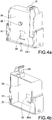
- the internal box body 2 comprises: a panel, a function rotating member placement slot 2A, a fixed column 2B, a second electrical connection pin fixing slot 2C, a remote linkage rod passing hole 2D, a first electrical connection pin fixing slot 2E, a spring fixing column 2F, a varistor placement slot 2G, a varistor's second electrode slot 2H, a varistor's first electrode passing hole 2K, a shear plane 2M and a failure status indicating area 2N, and the shear plane 2M has a slope 2M-2 formed with a smaller acute angle and a plane 2M-1; the varistor's first electrode passing hole 2K and the fixed column 2B are disposed on the panel 2A.
- the function rotating member 3 has a function rotating member fixing hole 3A, a spring connecting ring 3B, a soldering window 3C, a remote linkage rod contact wall 3D, a shear slope 3E, an arc shield plate 3F, a normal status indicating area 3G and a remote linkage notching 3H, and the color of the normal status indicating area 3G is different from the color of the failure status indicating area 2N of the internal box body 2, and the shear slope 3E has a slope 3E-1 formed with a smaller acute angle and a plane 3E-2, and the shear slope 3E is disposed on a side of the soldering window 3C.
- the external box body 1 has a monitoring hole 1A and a lock 1B.
- the internal box body 2 is made of an insulating, temperature resisting and flame retardant material.
- the first electrical connection pin 6 is disposed in a first pin fixing slot 2E electrically coupled to the internal box body 2 and has two positioning recesses 6A latched with a protruded member in the first pin fixing slot 2E.
- the second electrical connection pin 7 is fixed and installed in the fixing slot 2C of the second electrical connection pin 7, and the varistor 5 is installed into the varistor placement slot 2G of the internal box body 2, and the varistor's second electrode 5B is installed in the varistor's second electrode slot 2H and soldered with the first electrical connection pin 6 in the soldering area 6B, and the soldering area 6B is processed with a special surface treatment.
- the function rotating member 3 is made of an insulating, temperature resisting, and flame retardant material, installed in the function rotating member placement slot 2A, and sheathed on the fixed column 2B, and the function rotating member 3 is installed between the varistor 5 and the bridge bracket 8 and coupled to the elastic driving device 4, wherein the elastic driving device 4 is preferably a spring 4, and the spring of the elastic driving device 4 has an end coupled to the spring connecting ring 3B and the other end coupled to the spring fixing column 2F of the internal box body; and a fixing end 8B of the bridge bracket 8 is fixed and coupled to the second electrical connection pin 7 directly.
- the bridge bracket 8 is preferably pivotally coupled to the second electrical connection pin 7 in order to save the conductive wire coupled between them, so as to simplify the structure and reduce the quantity of components.
- the elastic driving device 4 drives the function rotating member 3 to rotate around the fixed column 2B.
- the spring is contracted to its original status, and the function rotating member is rotated counterclockwise around the fixed column 2B under the effect of the spring of the elastic driving device 4, and the function rotating member 3 is rotated to the second position, so that the failure status indicating area 2N of the internal box body 2 is situated at the monitoring hole 1A and exposed from the monitoring hole 1A to indicate that the varistor 5 is situated at the release status, and the function rotating member 3 is rotated from the remote linkage rod contact wall 3D to the remote linkage notching 3H with respect to the point of action of the remote linkage rod 9, so as to release the remote linkage rod 9; and the bridge bracket 8 will not rotate with the function rotating member 3, and the arc shield plate 3F provides a shielding effect between the bridge bracket 8 and the varistor's first electrode 5A, so that the wiring can be cut off more completely to prevent the conventional ceramic shielding body and release electrode plate from moving
- the shear plane 2M is disposed on the varistor's first electrode passing hole 2K, and the shear slope 3E of the function rotating member 3 is matched with the shear plane 2M of the varistor's first electrode passing hole 2K and rotated with the rotation of the function rotating member 3 to produce a shear movement, so as to cut off the soldering wiring more completely and quickly.
- the function rotating member 3 is rotated to the second position, the inner wall and the shear plane 2M of the varistor's first electrode passing hole 2K, the arc shield plate 3F of the function rotating member 3, and a surface of the varistor's first electrode 5A form a closed area, so that the electric arc can be eliminated more completely and quickly.
- the base is a pluggable structure having a cover 10, an electrical connection member and a remote device, and a latch slot 10A is formed on an inner sidewall of the U-shaped plug slot of the cover 10.
- the release mechanism When the release mechanism is plugged, the latch slot 10A and the lock 1B of the external box body 1 are latched with each other, and the release mechanism and the base can be coupled conveniently and quickly, and such arrangement prevents the release mechanism from being loosened or falling out, so as to improve the product safety.
- the electrical connection member has a metal claw 11 and a conductive strip 12, and the metal claw 11 and the conductive strip 12 are soldered by point soldering, and the metal claw 11 is clamped and coupled to the first electrical connection pin 6 and the second electrical connection pin 7 of the release mechanism to form a conducting channel.
- the remote device has a seat 13, a remote linkage rod 9, a remote linkage rod spring 17 and a remote connection terminal 20, and the remote connection terminal 20 may be coupled to a control system.
- the multi-stage surge protector is a two-stage surge protector, and the base of the surge protector of each stage is an independent linkage mechanical connection structure, and the remote device has as seat 13 with an end surface 13C, a sidewall 13E, a slider 14, a group of slide slots 13A, and the surge protector of each stage has a limit point 13B, a slider spring 16, a spring placement hole 13D, a bump 9B and a remote linkage rod internal hole 9C.
- the resultant force of two slider springs 16 is smaller than the elasticity of the single remote linkage rod spring 17.
- the slider 14 has a driven slope 14A, a micro switch driven block 14B, two spring fixing columns 14C and two positioning claws 14D, and the slider 14 is installed onto the slide slot 13A, and the positioning claw 14 blocks the end surface 13C, and the two spring fixing columns 14C have a slider spring 16 each, and an end of the slider spring 16 abuts a sidewall 13E, so that the sidewall 13E provides a continuous pushing force to the slider 14.
- Both of the remote linkage rod 9 and the remote linkage rod spring 17 are installed into the spring placement holes 13D of the surge protector of each stage respectively, and the remote linkage rod spring 17 is installed into the remote linkage rod internal hole 9C.
- the installed remote linkage rod 9 will not be popped out by the link rod spring 17.
- the micro switch 15 and the terminal block 19 are soldered onto the circuit board 18, and the circuit board 18 with the micro switch 15 and the terminal block 16 are installed into the seat 13.
- the remote linkage rod 9 is pressed down by the remote linkage rod contact wall 3D of the function rotating member 3, and the remote linkage rod spring 17 is situated at a maximum compression status.
- the driven slope 14A of the slider 14 is stopped at the right end of the slide slot 13A by the driving slope 9A of the remote linkage rod 9.
- the micro switch driven block 14B on the slider has no action on the micro switch button 15A, and the micro switch button 15A is situated at a naturally pop-up status which indicates that the varistor is situated at a normal operation status.
- the function rotating member 3 is rotated counterclockwise to the second position, and the function rotating member 3 is rotated from the remote linkage rod contact wall 3D to the remote linkage notching 3H with respect to the point of action of the remote linkage rod 9.
- the remote linkage rod 9 has an upward movement space and pops upward under the pushing effect of the remote linkage rod spring 17 to indicate that the varistor 5 is situated at the release status (which is the failure status).
- the driven slope 14A drives the slider 14 to move leftward along the slide slot 13A.
- the slider 14 is situated at a maximum displacement of the stroke, and the slider spring 16 is compressed, and the micro switch driven block 14B presses down the micro switch button 15A. Since the resultant force of two slider springs 16 is smaller than the elasticity of a single remote linkage rod spring 17, just a micro switch and a slider can release the surge protector of any level, and then the remote device will issue a failure warning signal to the control system to assure an effective feedback to the control end for each time of release and remind maintenance people to replace the surge protector timely, so as to achieve the effects of improving the safety and reliability of the surge protector, reducing the quantity of components, facilitating the manufacturing process, and lowering the cost.
- the release mechanism of this disclosure is capable of cutting off the electric arc and the soldering wiring between the varistor pin and the bridge bracket completely and quickly, while providing a status indication and a remote function.
- the base of this disclosure simply adopts a micro switch and a slider component, such that when a surge protector of any level is released, the remote device will issue a signal to improve the safety and reliability of the surge protector.
Landscapes
- Engineering & Computer Science (AREA)
- Microelectronics & Electronic Packaging (AREA)
- Physics & Mathematics (AREA)
- Electromagnetism (AREA)
- Thermistors And Varistors (AREA)
- Fuses (AREA)
Description
- This disclosure relates to a surge protector, and more particularly to a release mechanism and a base of the surge protector.
- A surge protector is generally applied in an electric circuit and used at home, office, or factory to prevent electric equipment from being damaged by transient overvoltage. When the electric circuit or a communication circuit produces a peak current or voltage by external interference, the surge protector is capable of conducting shunts in a very short time to avoid damaging other equipments in the circuit due to an electric surge.
- In general, a surge protector includes a metal oxide varistor (which is one of the varistors), and the varistor may be aged after a long time of use and generates heat easily. To prevent accidents such as a fire caused by the rise of temperature, the surge protector usually comes with a release mechanism connected in series with the varistor, so that when the temperature rises, the varistor is released and disconnected from the circuit. As disclosed in R.O.C. Pat. Application No.
201420368586.2 WO 2011/102811 A2 discloses another prior art concerned with a release mechanism for surge protector and surge protector thereof. - However, the conventional release mechanism has the following problems: (1) The convex side of the release electrode plate is installed into the positioning hole of the box body, so that after the soldering point is disconnected, the ceramic shielding body and the release electrode plate are moved together. If the moving distance is too short, the wiring cannot be cut off completely. (2) The right electrode pin and the release electrode plate are coupled with each other by the conductive wire and the solderable metal layer, so that the connecting structure is very complicated, and occupies a large space, and increases the failure rate.
- In view of the aforementioned drawbacks of the prior art, the discloser of this disclosure conducted extensive research and provided a feasible design to overcome the drawbacks of the prior art.
- Therefore, it is a primary objective of the present invention overcome the aforementioned problems of the prior art by providing a release mechanism according to
claim 1, a surge protector according toclaim 6 and a base according toclaim 14. According to the present invention, a bridge bracket of the release mechanism remains unmoved with respect to the internal box body and will not be rotated or moved together with the function rotating member. After the varistor is released, the function rotating member is rotated between the pin of the varistor and the bridge bracket so as to cut off the electric arc and the soldering wiring between the pin of the varistor pin and the bridge bracket and achieve a complete quick release, while providing a status indication and a remote function. - To achieve the aforementioned and other objectives, this disclosure provides a base applicable for a single-stage surge protector and a multi-stage surge protector, and the base adopts a mechanical connecting structure with different independent linkages, and just one micro switch and one slider are used, and each level has the linkage of the remote linkage rod and the slider. After the release mechanism of a surge protector of any level is released, the remote device will issue a signal to assure an effective feedback to a control system for each time of release, so as to achieve the effects of improving the safety and reliability of the surge protector, providing a simple mechanism with a small quantity of components, a stable connection, a convenient production, and lowering the cost.
- This disclosure further provides a release mechanism of a surge protector, and the release mechanism comprises an internal box body, a function rotating member, an elastic driving device, a first electrical connection pin, a second electrical connection pin and a bridge bracket accommodated in the a varistor, and the first electrical connection pin and the second electrical connection pin being plugged into the internal box body, and the varistor's second electrode and the first electrical connection pin being soldered, and the internal box body having a fixed column, and the function rotating member having an arc shield plate and a soldering window, and the function rotating member being sheathed on the fixed column and disposed between the varistor and the bridge bracket, and the elastic driving device having an end coupled to the function rotating member and the other end fixed to the internal box body, wherein an end of the bridge bracket directly fixed and coupled to the second electrical connection pin, such that when the varistor is situated at a normal status, the function rotating member is situated at a first position, and the other end of the bridge bracket is passed through the soldering window and soldered with a varistor's first electrode at low temperature, and when the varistor is situated at a release status, the elastic driving device drives the function rotating member to rotate around the fixed column, so that when the function rotating member is rotated to a second position, the arc shield plate provides a shielding effect between the bridge bracket and the varistor's first electrode.
- In the release mechanism of this disclosure, an end of the bridge bracket is fixed and coupled to the second electrical connection pin directly, and when the varistor is situated at a normal status, the function rotating member is situated at the first position, and the other end of the bridge bracket is passed through the soldering window and soldered with the varistor's first electrode at low temperature, and when the varistor is situated at a release status, the elastic driving device drives the function rotating member to rotate around the fixed column, so that when the function rotating member is rotated to the second position, the arc shield plate provides a shielding effect between the bridge bracket and the varistor's first electrode to break open the wiring and the electric arc. Since the bridge bracket is fixed and coupled to the second electrical connection pin directly, the bridge bracket is fixed with the internal box body to skip the conductive wire coupled between the bridge bracket and the electrical connection pin. When the function rotating member is rotated, the bridge bracket will not be rotated with the function rotating member, so that the wiring is cut off completely to prevent the ceramic shielding body and the release electrode plate of the conventional surge protector to move together. If the distance between them is too short, the wiring cannot be cut off completely.
- Preferably, the soldering window has a shear slope disposed on a side of the soldering window, and the internal box body has a panel, and the panel has a varistor's first electrode passing hole (2K) aligned precisely with the soldering window, and the varistor's first electrode passing hole has a shear plane, so that when the function rotating member is rotated, the shear slope and the shear plane of the soldering window are moved with respect to each other, so as to cut off the wiring more quickly and completely.
- Preferably, when the function rotating member is moved to a second position, an inner wall and the shear plane of the varistor's first electrode passing hole, the arc shield plate of the function rotating member, and a surface of the varistor's first electrode form a closed area which eliminates the electric arc more completely.
- Preferably, the release mechanism has an external box body, and the external box body has a monitoring hole, and the internal box body has a failure status indicating area, and the function rotating member has a normal status indicating area, and the color of the normal status indicating area and the color of the failure status indicating area are different, and the function rotating member is situated at a first position, and the normal status indicating area is exposed from the monitoring hole, and the function rotating member is rotated to a second position, so that the failure status indicating area is disposed at and exposed from the monitoring hole, so as to achieve the release indicating function.
- Preferably, the elastic driving device is a spring, and when the varistor is situated at a normal status, the function rotating member is situated at a first position, and the spring is situated at an stretched status, and when the varistor is situated at a release status, the spring is contracted, and the function rotating member is rotated from the first position to the second position around the fixed column under the effect of the spring. By using the spring to drive the function rotating member to rotate, a simple structure and an easy implementation can be achieved.
- Preferably, both of the function rotating member and the internal box body are made of a temperature resisting, insulating, and flame retardant material, so that the surge protector has the temperature resisting, insulating, and flame retardant properties.
- This disclosure further provides a surge protector comprising at least one varistor, a base, and at least one of the aforementioned release mechanisms.
- Preferably, the base comprises a remote device, and the remote device has at least one remote linkage rod, and the function rotating member has a remote linkage rod contact wall and a remote linkage notching, and when the function rotating member is situated at a first position, the remote linkage rod is pressed down by the remote linkage rod contact wall, and when the function rotating member is rotated from the first position to a second position, the function rotating member is rotated from the remote linkage rod contact wall to the remote linkage notching with respect to the point of action of the remote linkage rod to release the remote linkage rod, so as to achieve the remote function.
- Preferably, the remote device has a seat, at least one remote linkage rod spring and a micro switch, and the seat has a slide slot, a slider, at least one slider spring, and at least one spring placement hole, and the micro switch is installed in the seat and disposed under the slider, and the remote linkage rod spring is sheathed on the remote linkage rod and installed together with the remote linkage rod into the spring placement hole, and the slider is installed onto the slide slot, and at least one slider spring has an end coupled to the slider and the other end abutting against the seat sidewall; and when the function rotating member is situated at the first position, the remote linkage rod spring is situated at a maximum compression status, and the slider is stopped at an end of the slide slot by the remote linkage rod, and the slider has no action to the micro switch; and when the function rotating member is situated at a second position, at least one of the remote linkage rods pushes the slider to move along the slide slot under the pushing effect of the remote linkage rod spring, so that the slider presses the micro switch to indicate the status of the surge protector.
- Preferably, the remote linkage rod has a driving slope, and the slider has a driven slope, and when the function rotating member is situated at the first position, the driven slope of the slider is stopped by the driving slope of the remote linkage rod, and when the function rotating member is rotated to the second position, the driving slope pushes the driven slope, and the slider moves along the slide slot to press down the micro switch, wherein the driven slope and the driving slope are provided for the remote linkage rod to drive the slider to slide more stably.
- Preferably, the resultant force of all slider springs is smaller than the elasticity of the single remote linkage rod spring to guarantee that after a surge protector of any level is released, the remote device issues a signal to achieve the effects of providing a feedback to a control end effectively for each time of release, improving the safety and reliability of the surge protector, and reducing the quantity of components.
- Preferably, the base is a pluggable base, and the base has a cover, and the cover has an U-shaped plug slot, and an inner sidewall of the U-shaped plug slot has a latch slot, and the external box body of the release mechanism has a lock, and when the release mechanism is plugged into the base, the lock is latched to the latch slot formed on an inner sidewall of the U-shaped plug slot, so that the base can be connected to the release mechanism more conveniently and quickly to prevent the release mechanism from being loosened or falling off and improve the product safety.
- Preferably, the base has an electrical connection member, and the electrical connection member has a metal claw and a conductive strip, and the metal claw and the conductive strip are soldered and coupled to each other, and the metal claw and the first electrical connection pin and the second electrical connection pin of the release mechanism are clamped and coupled to form a conducting channel.
- Preferably, the seat has a limit point, and the remote linkage rod has a bump, such that when the remote linkage rod is set into the seat, the bump and the limit point are latched with each other, so as to assure that the remote linkage rod will not be popped out by the spring after installation.
- This disclosure further provides a base.
-
-
FIG. 1 is a schematic view of the overall structure of a surge protector of this disclosure; -
FIG. 2a is a schematic view of the structure of several release mechanisms of a surge protector of this disclosure; -
FIG. 2b is a schematic view of the structure of a base of a surge protector of this disclosure; -
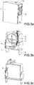
FIG. 3a is a schematic view of the structure of an external box body of a surge protector of this disclosure; -
FIG. 3b is a schematic view of the structure of a release mechanism of this disclosure; -
FIG. 3c is a schematic view of the structure of an internal box body a release mechanism of this disclosure; -
FIG. 4a is a front view of the structure of an internal box body a release mechanism of this disclosure; -
FIG. 4b is a back view of the structure of an internal box body a release mechanism of this disclosure; -
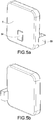
FIG. 5a is a front view of the structure of a varistor of this disclosure; -
FIG. 5b is a back view of the structure of a varistor of this disclosure; -
FIG. 6 is a schematic view of the structure of a bridge bracket of a release mechanism connected to a second electrical connection pin in accordance with this disclosure; -
FIG. 7 is a schematic view of the structure of a release mechanism of a first electrical connection pin of this disclosure; -
FIG. 8a is a front view of the structure of a function rotating member of a release mechanism of this disclosure; -
FIG. 8b is a back view of the structure of a function rotating member of a release mechanism of this disclosure; -
FIG. 9a is a schematic view showing a normal operation status of a release mechanism of this disclosure; -
FIG. 9b is a schematic view showing a release status of a release mechanism of this disclosure; -
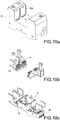
FIG. 10a is a schematic view of the structure of a cover of a surge protector of this disclosure; -
FIG. 10b is a schematic view of the structure of a metal claw of a base of a surge protector of this disclosure; -
FIG. 10c is a schematic view of the structure of a seat of a base of a surge protector in accordance with this disclosure; -
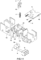
FIG. 11 is an exploded view of a remote device installed in a base in accordance with this disclosure; -
FIG. 12a is a front view of a remote linkage rod of a remote device of this disclosure; -
FIG. 12b is a back view of a remote linkage rod of a remote device of this disclosure; -
FIG. 13a is a front view of a combination of a slider and a slider spring of a base of a remote device in accordance with this disclosure; -
FIG. 13b is a back view of a slider of a seat of a remote device in accordance with this disclosure; -
FIG. 14 is a schematic view showing the status of a remote device before the release mechanism is released in accordance with this disclosure; -
FIG. 15 is a schematic view showing the status of a remote device after the release mechanism is released in accordance with this disclosure; -
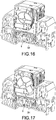
FIG. 16 is a schematic view showing the linkage of a base before the release mechanism is released in accordance with this disclosure; and -
FIG. 17 is a schematic view showing the linkage of a base after the release mechanism is released in accordance with this disclosure. - The technical contents of the present invention will become apparent with the detailed description of preferred embodiments accompanied with the illustration of related drawings as follows.
- Preferred embodiments of the release mechanism, the base and the surge protector of this disclosure will be described and illustrated according to the accompanied drawings as follows.
- With reference to
FIGS. 1∼7 for a release mechanism of a surge protector, the release mechanism comprises anexternal box body 1, aninternal box body 2, a function rotating member 3, anelastic driving device 4, a firstelectrical connection pin 6, a secondelectrical connection pin 7, and abridge bracket 8. - With reference to
FIGS. 4a and 4b , theinternal box body 2 comprises: a panel, a function rotatingmember placement slot 2A, a fixedcolumn 2B, a second electrical connectionpin fixing slot 2C, a remote linkagerod passing hole 2D, a first electrical connectionpin fixing slot 2E, aspring fixing column 2F, avaristor placement slot 2G, a varistor'ssecond electrode slot 2H, a varistor's firstelectrode passing hole 2K, ashear plane 2M and a failurestatus indicating area 2N, and theshear plane 2M has aslope 2M-2 formed with a smaller acute angle and aplane 2M-1; the varistor's firstelectrode passing hole 2K and the fixedcolumn 2B are disposed on thepanel 2A. - With reference to
FIGS. 8a and 8b , the function rotating member 3 has a function rotatingmember fixing hole 3A, aspring connecting ring 3B, asoldering window 3C, a remote linkagerod contact wall 3D, ashear slope 3E, anarc shield plate 3F, a normalstatus indicating area 3G and a remote linkage notching 3H, and the color of the normalstatus indicating area 3G is different from the color of the failurestatus indicating area 2N of theinternal box body 2, and theshear slope 3E has aslope 3E-1 formed with a smaller acute angle and aplane 3E-2, and theshear slope 3E is disposed on a side of thesoldering window 3C. - In
FIG. 3a , theexternal box body 1 has amonitoring hole 1A and alock 1B. - In
FIGS. 3a∼8b , theinternal box body 2 is made of an insulating, temperature resisting and flame retardant material. The firstelectrical connection pin 6 is disposed in a firstpin fixing slot 2E electrically coupled to theinternal box body 2 and has twopositioning recesses 6A latched with a protruded member in the firstpin fixing slot 2E. The secondelectrical connection pin 7 is fixed and installed in the fixingslot 2C of the secondelectrical connection pin 7, and thevaristor 5 is installed into thevaristor placement slot 2G of theinternal box body 2, and the varistor'ssecond electrode 5B is installed in the varistor'ssecond electrode slot 2H and soldered with the firstelectrical connection pin 6 in thesoldering area 6B, and thesoldering area 6B is processed with a special surface treatment. - The function rotating member 3 is made of an insulating, temperature resisting, and flame retardant material, installed in the function rotating
member placement slot 2A, and sheathed on the fixedcolumn 2B, and the function rotating member 3 is installed between thevaristor 5 and thebridge bracket 8 and coupled to theelastic driving device 4, wherein theelastic driving device 4 is preferably aspring 4, and the spring of theelastic driving device 4 has an end coupled to thespring connecting ring 3B and the other end coupled to thespring fixing column 2F of the internal box body; and a fixingend 8B of thebridge bracket 8 is fixed and coupled to the secondelectrical connection pin 7 directly. Thebridge bracket 8 is preferably pivotally coupled to the secondelectrical connection pin 7 in order to save the conductive wire coupled between them, so as to simplify the structure and reduce the quantity of components. - With reference to
FIGS. 8a∼9b , when thevaristor 5 is situated at a normal status, the function rotating member 3 is situated at the first position, and the spring of theelastic driving device 4 is situated at the stretched status, and asoldering end 8A of thebridge bracket 8 is deformed by forces and then soldered with thesoldering window 3C, the varistor's firstelectrode passing hole 2K and the varistor'sfirst electrode 5A at low temperature, and thebridge bracket 8 is made of metal with an elasticity, so that the solderedbridge bracket 8 is capable of producing a restoring force according to the elastic deformation of the elastic body; and the normalstatus indicating area 3G of the function rotating member 3 is exposed from themonitoring hole 1A to indicate a normal status, and theremote linkage rod 9 of the surge protector is pressed down by the remote linkagerod contact wall 3D. - When the
varistor 5 is situated at the release status, theelastic driving device 4 drives the function rotating member 3 to rotate around the fixedcolumn 2B. In other words, the spring is contracted to its original status, and the function rotating member is rotated counterclockwise around the fixedcolumn 2B under the effect of the spring of theelastic driving device 4, and the function rotating member 3 is rotated to the second position, so that the failurestatus indicating area 2N of theinternal box body 2 is situated at themonitoring hole 1A and exposed from themonitoring hole 1A to indicate that thevaristor 5 is situated at the release status, and the function rotating member 3 is rotated from the remote linkagerod contact wall 3D to the remote linkage notching 3H with respect to the point of action of theremote linkage rod 9, so as to release theremote linkage rod 9; and thebridge bracket 8 will not rotate with the function rotating member 3, and thearc shield plate 3F provides a shielding effect between thebridge bracket 8 and the varistor'sfirst electrode 5A, so that the wiring can be cut off more completely to prevent the conventional ceramic shielding body and release electrode plate from moving together. If distance between them is too short, the wiring cannot be cut off completely. - Preferably, the
shear plane 2M is disposed on the varistor's firstelectrode passing hole 2K, and theshear slope 3E of the function rotating member 3 is matched with theshear plane 2M of the varistor's firstelectrode passing hole 2K and rotated with the rotation of the function rotating member 3 to produce a shear movement, so as to cut off the soldering wiring more completely and quickly. When the function rotating member 3 is rotated to the second position, the inner wall and theshear plane 2M of the varistor's firstelectrode passing hole 2K, thearc shield plate 3F of the function rotating member 3, and a surface of the varistor'sfirst electrode 5A form a closed area, so that the electric arc can be eliminated more completely and quickly. - With reference to
FIGS. 10a and3a , the base is a pluggable structure having acover 10, an electrical connection member and a remote device, and alatch slot 10A is formed on an inner sidewall of the U-shaped plug slot of thecover 10. When the release mechanism is plugged, thelatch slot 10A and thelock 1B of theexternal box body 1 are latched with each other, and the release mechanism and the base can be coupled conveniently and quickly, and such arrangement prevents the release mechanism from being loosened or falling out, so as to improve the product safety. - With reference to
FIGS. 10b and3b , the electrical connection member has ametal claw 11 and aconductive strip 12, and themetal claw 11 and theconductive strip 12 are soldered by point soldering, and themetal claw 11 is clamped and coupled to the firstelectrical connection pin 6 and the secondelectrical connection pin 7 of the release mechanism to form a conducting channel. - With reference to
FIGS. 10c and11 , the remote device has aseat 13, aremote linkage rod 9, a remotelinkage rod spring 17 and aremote connection terminal 20, and theremote connection terminal 20 may be coupled to a control system. - With reference to
FIGS. 11∼13b , the multi-stage surge protector is a two-stage surge protector, and the base of the surge protector of each stage is an independent linkage mechanical connection structure, and the remote device has asseat 13 with anend surface 13C, asidewall 13E, aslider 14, a group ofslide slots 13A, and the surge protector of each stage has alimit point 13B, aslider spring 16, aspring placement hole 13D, abump 9B and a remote linkage rodinternal hole 9C. The resultant force of two slider springs 16 is smaller than the elasticity of the single remotelinkage rod spring 17. Theslider 14 has a drivenslope 14A, a micro switch drivenblock 14B, twospring fixing columns 14C and twopositioning claws 14D, and theslider 14 is installed onto theslide slot 13A, and thepositioning claw 14 blocks theend surface 13C, and the twospring fixing columns 14C have aslider spring 16 each, and an end of theslider spring 16 abuts asidewall 13E, so that thesidewall 13E provides a continuous pushing force to theslider 14. Both of theremote linkage rod 9 and the remotelinkage rod spring 17 are installed into thespring placement holes 13D of the surge protector of each stage respectively, and the remotelinkage rod spring 17 is installed into the remote linkage rodinternal hole 9C. With the effect of thebump 9B and thelimit point 13B, the installedremote linkage rod 9 will not be popped out by thelink rod spring 17. Themicro switch 15 and theterminal block 19 are soldered onto thecircuit board 18, and thecircuit board 18 with themicro switch 15 and theterminal block 16 are installed into theseat 13. - With reference to
FIGS. 14 and16 for avaristor 5 situated at the normal operation status, theremote linkage rod 9 is pressed down by the remote linkagerod contact wall 3D of the function rotating member 3, and the remotelinkage rod spring 17 is situated at a maximum compression status. Under the pushing effect of theslider spring 16, the drivenslope 14A of theslider 14 is stopped at the right end of theslide slot 13A by the drivingslope 9A of theremote linkage rod 9. Now, the micro switch drivenblock 14B on the slider has no action on themicro switch button 15A, and themicro switch button 15A is situated at a naturally pop-up status which indicates that the varistor is situated at a normal operation status. - With reference to
FIGS. 15 and17 for avaristor 5 situated at the release status, the function rotating member 3 is rotated counterclockwise to the second position, and the function rotating member 3 is rotated from the remote linkagerod contact wall 3D to the remote linkage notching 3H with respect to the point of action of theremote linkage rod 9. When the functional rotating member 3 is rotated to a position above theremote linkage rod 9, theremote linkage rod 9 has an upward movement space and pops upward under the pushing effect of the remotelinkage rod spring 17 to indicate that thevaristor 5 is situated at the release status (which is the failure status). Under the elastic effect of the drivingslope 9A, the drivenslope 14A drives theslider 14 to move leftward along theslide slot 13A. After theremote linkage rod 9 has been popped completely, theslider 14 is situated at a maximum displacement of the stroke, and theslider spring 16 is compressed, and the micro switch drivenblock 14B presses down themicro switch button 15A. Since the resultant force of two slider springs 16 is smaller than the elasticity of a single remotelinkage rod spring 17, just a micro switch and a slider can release the surge protector of any level, and then the remote device will issue a failure warning signal to the control system to assure an effective feedback to the control end for each time of release and remind maintenance people to replace the surge protector timely, so as to achieve the effects of improving the safety and reliability of the surge protector, reducing the quantity of components, facilitating the manufacturing process, and lowering the cost. - In summation of the description above, the release mechanism of this disclosure is capable of cutting off the electric arc and the soldering wiring between the varistor pin and the bridge bracket completely and quickly, while providing a status indication and a remote function.
- The base of this disclosure simply adopts a micro switch and a slider component, such that when a surge protector of any level is released, the remote device will issue a signal to improve the safety and reliability of the surge protector.
Claims (14)
- A release mechanism of a surge protector, the release mechanism comprising an internal box body (2), a function rotating member (3), an elastic driving device (4), a first electrical connection pin (6), a second electrical connection pin (7) and a bridge bracket (8) accommodated in the a varistor (5), and the first electrical connection pin (6) and the second electrical connection pin (7) being plugged into the internal box body (2), and the varistor's second electrode (5B) and the first electrical connection pin (6) being soldered, and the internal box body (2) having a fixed column (2B), and the function rotating member (3) having an arc shield plate (3F) and a soldering window (3C), and the function rotating member (3) being sheathed on the fixed column (2B) and disposed between the varistor (5) and the bridge bracket (8), and the elastic driving device (4) having an end coupled to the function rotating member (3) and the other end fixed to the internal box body (2), wherein an end of the bridge bracket (8) is directly fixed and coupled to the second electrical connection pin (7), such that when the varistor (5) is situated at a normal status, the function rotating member (3) is situated at a first position, and the other end of the bridge bracket (8) is passed through the soldering window (3C) and soldered with a varistor's first electrode (5A) at low temperature, and when the varistor (5) is situated at a release status, the elastic driving device (4) drives the function rotating member (3) to rotate around the fixed column (2B), so that when the function rotating member (3) is rotated to a second position, the arc shield plate (3F) provides a shielding effect between the bridge bracket (8) and the varistor's first electrode (5A);
wherein the release mechanism has an external box body (1), and the external box body (1) has a monitoring hole (1A), and the internal box body (2) has a failure status indicating area (2N), and the function rotating member (3) has a normal status indicating area (3G), and the color of the normal status indicating area (3G) and the color of the failure status indicating area (2N) are different, and the function rotating member (3) is situated at a first position, and the normal status indicating area (3G) is exposed from the monitoring hole (1A), and the function rotating member (3) is rotated to a second position, so that the failure status indicating area (2N) is disposed at and exposed from the monitoring hole (1A). - The release mechanism of claim 1, wherein the soldering window (3C) has a shear slope (3E) disposed on a side of the soldering window (3C), and the internal box body (2) has a panel (2A), and the panel (2A) has a varistor's first electrode passing hole (2K) aligned precisely with the soldering window (3C), and the varistor's first electrode passing hole (2K) has a shear plane (2M), so that when the function rotating member (3) is rotated, the shear slope (2M) and the shear plane (3E) of the soldering window (3C) are moved with respect to each other.
- The release mechanism of claim 1 or 2, wherein when the function rotating member (3) is rotated to a second position, an inner wall and the shear plane (2M) of the varistor's first electrode passing hole (2K), the arc shield plate (3F) of the function rotating member (3), and a surface of the varistor's first electrode (5A) form a closed area.
- The release mechanism of any of the claims 1 to 3, wherein the elastic driving device (4) is a spring, and when the varistor (5) is situated at a normal status, the function rotating member (3) is situated at a first position, and the spring is situated at a stretched status, and when the varistor (5) is situated at a release status, the spring is contracted, and the function rotating member (3) is rotated from the first position to the second position around the fixed column (2B) under the effect of the spring.
- The release mechanism of any of the claims 1 to 4, wherein both of the function rotating member (3) and the internal box body (2) are made of a temperature resisting, insulating, and flame retardant material.
- A surge protector, comprising:
at least one varistor (5); a base; and at least one release mechanism according to any one of claims 1 to 5. - The surge protector of claim 6, wherein the base includes a remote device, and the remote device has at least one remote linkage rod (9), and the function rotating member (3) has a remote linkage rod contact wall (3D) and a remote linkage notching (3H), and when the function rotating member (3) is situated at a first position, the remote linkage rod (9) is pressed down by the remote linkage rod contact wall (3D), and when the function rotating member (3) is rotated from the first position to the second position, the function rotating member (3) is rotated from the remote linkage rod contact wall (3D) to the remote linkage notching (3H) with respect to the point of action of the remote linkage rod (9) to release the remote linkage rod (9).
- The surge protector of claim 6 or 7, wherein the remote device has a seat (13), a micro switch (15), at least one slider spring (16) and at least one remote linkage rod spring (17), and the seat (13) has a slide slot (13A), a slider (14), at least one slider spring (16), and at least one spring placement hole (13D), and the micro switch (15) is installed in the seat (13) and disposed under the slider (14), and the remote linkage rod spring (17) is sheathed on the remote linkage rod (9) and installed together with the remote linkage rod (9) in the spring placement hole (13D), and the slider (14) is installed onto the slide slot (13A), and the slider spring (16) has an end coupled to the slider (14) and the other end abutting against the seat sidewall (13E) and when the function rotating member (3) is situated at the first position, the remote linkage rod spring (17) is situated at a maximum compression status, and an end of the slider (14) is stopped by the remote linkage rod (9) at an end of the slide slot (13A), and the slider (14) has no action on the micro switch (15), and when the function rotating member (3) is situated at the second position, at least one of the remote linkage rods (9) pushes the slider (14) to move along the slide slot (13A) under the pushing effect of the remote linkage rod spring (17), so that the slider (14) presses the micro switch (15).
- The surge protector of claim 8, wherein the remote linkage rod (9) has a driving slope (9A), and the slider (14) has a driven slope (14A), and when the function rotating member (3) is situated at the first position, the driven slope (14A) of the slider (14) is stopped by the driving slope (9A) of the remote linkage rod (9), and when the function rotating member (3) is rotated to the second position, the driving slope (9A) pushes the driven slope (14A) to move the slider (14) along the slide slot (13A), so as to press the micro switch (15).
- The surge protector of claim 8 or 9, wherein the resultant force of all slider springs (16) is smaller than the elasticity of the single remote linkage rod spring (17).
- The surge protector of any of the claims 7 to 10, wherein the base is a pluggable base, and the base has a cover (10), and the cover (10) has an U-shaped plug slot, and an inner sidewall of the U-shaped plug slot has a latch slot (10A), and the external box body (1) of the release mechanism has a lock (1B), and when the release mechanism is inserted into the base, the lock (1B) is latched to the latch slot (10A) formed on the inner sidewall of the U-shaped plug slot.
- The surge protector of any of the claims 7 to 10, wherein the base has an electrical connection member, and the electrical connection member has a metal claw (11) and a conductive strip (12), and the metal claw (11) and the conductive strip (12) are soldered, and the metal claw (11) and the first electrical connection pin (6) and the second electrical connection pin (7) of the release mechanism are clamped and coupled to form a conducting channel.
- The surge protector of any of the claims 7 to 12, wherein the seat (13) has a limit point (13B), and the remote linkage rod (9) has a bump (9B), and when the remote linkage rod (9) is set in the seat (13), the bump (9B) and the limit point (13B) are latched with each other.
- A base, applied to a surge protector according to any one of claims 6 to 13.
Priority Applications (1)
| Application Number | Priority Date | Filing Date | Title |
|---|---|---|---|
| EP17177926.7A EP3422370B8 (en) | 2017-06-26 | 2017-06-26 | Surge protector, and release mechanism and base thereof |
Applications Claiming Priority (1)
| Application Number | Priority Date | Filing Date | Title |
|---|---|---|---|
| EP17177926.7A EP3422370B8 (en) | 2017-06-26 | 2017-06-26 | Surge protector, and release mechanism and base thereof |
Publications (3)
| Publication Number | Publication Date |
|---|---|
| EP3422370A1 EP3422370A1 (en) | 2019-01-02 |
| EP3422370B1 true EP3422370B1 (en) | 2019-12-18 |
| EP3422370B8 EP3422370B8 (en) | 2020-12-23 |
Family
ID=59227569
Family Applications (1)
| Application Number | Title | Priority Date | Filing Date |
|---|---|---|---|
| EP17177926.7A Active EP3422370B8 (en) | 2017-06-26 | 2017-06-26 | Surge protector, and release mechanism and base thereof |
Country Status (1)
| Country | Link |
|---|---|
| EP (1) | EP3422370B8 (en) |
Cited By (2)
| Publication number | Priority date | Publication date | Assignee | Title |
|---|---|---|---|---|
| WO2022104516A1 (en) * | 2020-11-17 | 2022-05-27 | 杭州昼锦科技有限公司 | High-security computer encryption auxiliary apparatus with data protection function |
| WO2024072672A3 (en) * | 2022-09-30 | 2024-08-02 | Mersen Usa Ep Corp. | Surge protection device, mov with integrated short circuit protection, insertion system and arc shield |
Families Citing this family (11)
| Publication number | Priority date | Publication date | Assignee | Title |
|---|---|---|---|---|
| CN111446599A (en) * | 2020-03-30 | 2020-07-24 | 隆科电子(惠阳)有限公司 | SPD plug-in module, SPD base and plug-in type SPD |
| CN112309772B (en) * | 2020-10-26 | 2024-02-13 | 国网山东省电力公司昌邑市供电公司 | A portable relay protector |
| US20240222962A1 (en) * | 2021-04-30 | 2024-07-04 | SHANGHAI CHENZHU INSTRUMENT Co.,Ltd. | Surge protection module and surge protection device |
| WO2022226959A1 (en) * | 2021-04-30 | 2022-11-03 | 上海辰竹防雷科技有限公司 | Linkage mechanism, base, and surge protecting device |
| CN113311200B (en) * | 2021-06-09 | 2024-09-17 | 湖北金顿电气有限公司 | Power supply equipment protection triggering condition sensitivity detection device |
| CN115513920B (en) * | 2022-10-24 | 2024-04-05 | 国网江苏省电力有限公司连云港供电分公司 | Lightning protection device for secondary equipment of transformer substation |
| CN116613718A (en) * | 2023-05-19 | 2023-08-18 | 深圳市海鹏信电子股份有限公司 | 1U panel embedded surge protector and electrical equipment |
| CN116654579B (en) * | 2023-06-30 | 2026-03-10 | 杉金光电(南京)有限公司 | Prevent broken locating lever device of polaroid transportation clamp |
| CN120165348A (en) * | 2023-12-14 | 2025-06-17 | 施耐德电气工业公司 | An alarm system and a surge protector |
| CN118040627A (en) * | 2024-04-12 | 2024-05-14 | 浙江大展电器有限公司 | Special protection integrated surge protector |
| CN119743855B (en) * | 2025-02-14 | 2025-11-18 | 广州建龙电器有限公司 | A surge-proof electric heating tube based on a gas discharge tube |
Family Cites Families (4)
| Publication number | Priority date | Publication date | Assignee | Title |
|---|---|---|---|---|
| US6430019B1 (en) * | 1998-06-08 | 2002-08-06 | Ferraz S.A. | Circuit protection device |
| SI23303A (en) * | 2010-02-19 | 2011-08-31 | ISKRA ZAŠČITE d.o.o. | Surge arrestor with rotary disc and electronic assembly for improving operational reliability |
| SI24171A (en) * | 2012-08-11 | 2014-02-28 | ISKRA ZAĹ ÄŚITE d.o.o. | The mechanism for the signaling of disconnection in the surge of protective device |
| CN203933002U (en) * | 2014-07-04 | 2014-11-05 | 隆科电子(惠阳)有限公司 | A kind of surge absoption protector with the hot detaching structure of displacement interrupter-type |
-
2017
- 2017-06-26 EP EP17177926.7A patent/EP3422370B8/en active Active
Non-Patent Citations (1)
| Title |
|---|
| None * |
Cited By (2)
| Publication number | Priority date | Publication date | Assignee | Title |
|---|---|---|---|---|
| WO2022104516A1 (en) * | 2020-11-17 | 2022-05-27 | 杭州昼锦科技有限公司 | High-security computer encryption auxiliary apparatus with data protection function |
| WO2024072672A3 (en) * | 2022-09-30 | 2024-08-02 | Mersen Usa Ep Corp. | Surge protection device, mov with integrated short circuit protection, insertion system and arc shield |
Also Published As
| Publication number | Publication date |
|---|---|
| EP3422370A1 (en) | 2019-01-02 |
| EP3422370B8 (en) | 2020-12-23 |
Similar Documents
| Publication | Publication Date | Title |
|---|---|---|
| EP3422370A1 (en) | Surge protector, and release mechanism and base thereof | |
| US10593501B2 (en) | Surge protector and base therof | |
| CN108962699B (en) | Tripping mechanism for surge protector, base and surge protector | |
| CN104505319B (en) | Depart from and hide arc device and be provided with its small size High-security surge protection device | |
| CN207199547U (en) | Tripping mechanism, base and surge protector for surge protector | |
| CN110350501A (en) | Three-phase surge protection device | |
| US11070010B2 (en) | Overheating destructive disconnecting method for switch | |
| US10529508B2 (en) | Signal feedback apparatus | |
| EP3422385B1 (en) | Signal feedback apparatus | |
| US11024478B2 (en) | Overheating destructive disconnecting method for switch | |
| CN210897163U (en) | Circuit breaker | |
| CN108933066B (en) | Integrated tripping and arc extinguishing indication remote signaling mechanism of surge protector and surge protector | |
| WO2019037462A1 (en) | Wall switch with overcurrent protection function | |
| CN108231498B (en) | Surge protector | |
| CN206059309U (en) | A kind of interlocking mechanism, the control panel and chopper that possess the interlocking mechanism | |
| CN213071005U (en) | Miniature temperature controller | |
| CN108766843B (en) | Lightning current-tolerant micro switch | |
| CN209981126U (en) | A tripping device for a surge protector | |
| CN108962698B (en) | Tripping mechanism of surge protector and surge protector | |
| CN206059308U (en) | A kind of interlocking mechanism, the control panel and chopper that possess the interlocking mechanism | |
| CN218939463U (en) | Micro-switch | |
| CN108962695B (en) | Signal feedback device | |
| CN220358045U (en) | Remote signaling trigger assembly for circuit on-off feedback | |
| CN220368472U (en) | Novel SPD assembly | |
| CN216355964U (en) | Surge protection device |
Legal Events
| Date | Code | Title | Description |
|---|---|---|---|
| PUAI | Public reference made under article 153(3) epc to a published international application that has entered the european phase |
Free format text: ORIGINAL CODE: 0009012 |
|
| STAA | Information on the status of an ep patent application or granted ep patent |
Free format text: STATUS: REQUEST FOR EXAMINATION WAS MADE |
|
| 17P | Request for examination filed |
Effective date: 20180420 |
|
| AK | Designated contracting states |
Kind code of ref document: A1 Designated state(s): AL AT BE BG CH CY CZ DE DK EE ES FI FR GB GR HR HU IE IS IT LI LT LU LV MC MK MT NL NO PL PT RO RS SE SI SK SM TR |
|
| AX | Request for extension of the european patent |
Extension state: BA ME |
|
| GRAP | Despatch of communication of intention to grant a patent |
Free format text: ORIGINAL CODE: EPIDOSNIGR1 |
|
| STAA | Information on the status of an ep patent application or granted ep patent |
Free format text: STATUS: GRANT OF PATENT IS INTENDED |
|
| RIC1 | Information provided on ipc code assigned before grant |
Ipc: H01H 71/20 20060101ALN20190704BHEP Ipc: H02H 3/22 20060101ALI20190704BHEP Ipc: H01C 7/12 20060101AFI20190704BHEP |
|
| RIC1 | Information provided on ipc code assigned before grant |
Ipc: H01C 7/12 20060101AFI20190718BHEP Ipc: H01H 71/20 20060101ALN20190718BHEP Ipc: H02H 3/22 20060101ALI20190718BHEP |
|
| INTG | Intention to grant announced |
Effective date: 20190802 |
|
| RIC1 | Information provided on ipc code assigned before grant |
Ipc: H01C 7/12 20060101AFI20190719BHEP Ipc: H01H 71/20 20060101ALN20190719BHEP Ipc: H02H 3/22 20060101ALI20190719BHEP |
|
| GRAS | Grant fee paid |
Free format text: ORIGINAL CODE: EPIDOSNIGR3 |
|
| GRAA | (expected) grant |
Free format text: ORIGINAL CODE: 0009210 |
|
| STAA | Information on the status of an ep patent application or granted ep patent |
Free format text: STATUS: THE PATENT HAS BEEN GRANTED |
|
| AK | Designated contracting states |
Kind code of ref document: B1 Designated state(s): AL AT BE BG CH CY CZ DE DK EE ES FI FR GB GR HR HU IE IS IT LI LT LU LV MC MK MT NL NO PL PT RO RS SE SI SK SM TR |
|
| REG | Reference to a national code |
Ref country code: CH Ref legal event code: EP |
|
| REG | Reference to a national code |
Ref country code: IE Ref legal event code: FG4D |
|
| REG | Reference to a national code |
Ref country code: DE Ref legal event code: R096 Ref document number: 602017009774 Country of ref document: DE |
|
| REG | Reference to a national code |
Ref country code: AT Ref legal event code: REF Ref document number: 1215499 Country of ref document: AT Kind code of ref document: T Effective date: 20200115 |
|
| REG | Reference to a national code |
Ref country code: NL Ref legal event code: MP Effective date: 20191218 |
|
| PG25 | Lapsed in a contracting state [announced via postgrant information from national office to epo] |
Ref country code: GR Free format text: LAPSE BECAUSE OF FAILURE TO SUBMIT A TRANSLATION OF THE DESCRIPTION OR TO PAY THE FEE WITHIN THE PRESCRIBED TIME-LIMIT Effective date: 20200319 Ref country code: LT Free format text: LAPSE BECAUSE OF FAILURE TO SUBMIT A TRANSLATION OF THE DESCRIPTION OR TO PAY THE FEE WITHIN THE PRESCRIBED TIME-LIMIT Effective date: 20191218 Ref country code: NO Free format text: LAPSE BECAUSE OF FAILURE TO SUBMIT A TRANSLATION OF THE DESCRIPTION OR TO PAY THE FEE WITHIN THE PRESCRIBED TIME-LIMIT Effective date: 20200318 Ref country code: SE Free format text: LAPSE BECAUSE OF FAILURE TO SUBMIT A TRANSLATION OF THE DESCRIPTION OR TO PAY THE FEE WITHIN THE PRESCRIBED TIME-LIMIT Effective date: 20191218 Ref country code: LV Free format text: LAPSE BECAUSE OF FAILURE TO SUBMIT A TRANSLATION OF THE DESCRIPTION OR TO PAY THE FEE WITHIN THE PRESCRIBED TIME-LIMIT Effective date: 20191218 Ref country code: BG Free format text: LAPSE BECAUSE OF FAILURE TO SUBMIT A TRANSLATION OF THE DESCRIPTION OR TO PAY THE FEE WITHIN THE PRESCRIBED TIME-LIMIT Effective date: 20200318 Ref country code: FI Free format text: LAPSE BECAUSE OF FAILURE TO SUBMIT A TRANSLATION OF THE DESCRIPTION OR TO PAY THE FEE WITHIN THE PRESCRIBED TIME-LIMIT Effective date: 20191218 |
|
| REG | Reference to a national code |
Ref country code: LT Ref legal event code: MG4D |
|
| PG25 | Lapsed in a contracting state [announced via postgrant information from national office to epo] |
Ref country code: RS Free format text: LAPSE BECAUSE OF FAILURE TO SUBMIT A TRANSLATION OF THE DESCRIPTION OR TO PAY THE FEE WITHIN THE PRESCRIBED TIME-LIMIT Effective date: 20191218 Ref country code: HR Free format text: LAPSE BECAUSE OF FAILURE TO SUBMIT A TRANSLATION OF THE DESCRIPTION OR TO PAY THE FEE WITHIN THE PRESCRIBED TIME-LIMIT Effective date: 20191218 |
|
| PG25 | Lapsed in a contracting state [announced via postgrant information from national office to epo] |
Ref country code: AL Free format text: LAPSE BECAUSE OF FAILURE TO SUBMIT A TRANSLATION OF THE DESCRIPTION OR TO PAY THE FEE WITHIN THE PRESCRIBED TIME-LIMIT Effective date: 20191218 |
|
| PG25 | Lapsed in a contracting state [announced via postgrant information from national office to epo] |
Ref country code: NL Free format text: LAPSE BECAUSE OF FAILURE TO SUBMIT A TRANSLATION OF THE DESCRIPTION OR TO PAY THE FEE WITHIN THE PRESCRIBED TIME-LIMIT Effective date: 20191218 Ref country code: EE Free format text: LAPSE BECAUSE OF FAILURE TO SUBMIT A TRANSLATION OF THE DESCRIPTION OR TO PAY THE FEE WITHIN THE PRESCRIBED TIME-LIMIT Effective date: 20191218 Ref country code: CZ Free format text: LAPSE BECAUSE OF FAILURE TO SUBMIT A TRANSLATION OF THE DESCRIPTION OR TO PAY THE FEE WITHIN THE PRESCRIBED TIME-LIMIT Effective date: 20191218 Ref country code: RO Free format text: LAPSE BECAUSE OF FAILURE TO SUBMIT A TRANSLATION OF THE DESCRIPTION OR TO PAY THE FEE WITHIN THE PRESCRIBED TIME-LIMIT Effective date: 20191218 Ref country code: PT Free format text: LAPSE BECAUSE OF FAILURE TO SUBMIT A TRANSLATION OF THE DESCRIPTION OR TO PAY THE FEE WITHIN THE PRESCRIBED TIME-LIMIT Effective date: 20200513 |
|
| PG25 | Lapsed in a contracting state [announced via postgrant information from national office to epo] |
Ref country code: SM Free format text: LAPSE BECAUSE OF FAILURE TO SUBMIT A TRANSLATION OF THE DESCRIPTION OR TO PAY THE FEE WITHIN THE PRESCRIBED TIME-LIMIT Effective date: 20191218 Ref country code: IS Free format text: LAPSE BECAUSE OF FAILURE TO SUBMIT A TRANSLATION OF THE DESCRIPTION OR TO PAY THE FEE WITHIN THE PRESCRIBED TIME-LIMIT Effective date: 20200418 Ref country code: SK Free format text: LAPSE BECAUSE OF FAILURE TO SUBMIT A TRANSLATION OF THE DESCRIPTION OR TO PAY THE FEE WITHIN THE PRESCRIBED TIME-LIMIT Effective date: 20191218 |
|
| REG | Reference to a national code |
Ref country code: DE Ref legal event code: R097 Ref document number: 602017009774 Country of ref document: DE |
|
| REG | Reference to a national code |
Ref country code: AT Ref legal event code: MK05 Ref document number: 1215499 Country of ref document: AT Kind code of ref document: T Effective date: 20191218 |
|
| PLAA | Information modified related to event that no opposition was filed |
Free format text: ORIGINAL CODE: 0009299DELT |
|
| PLBE | No opposition filed within time limit |
Free format text: ORIGINAL CODE: 0009261 |
|
| STAA | Information on the status of an ep patent application or granted ep patent |
Free format text: STATUS: NO OPPOSITION FILED WITHIN TIME LIMIT |
|
| PG25 | Lapsed in a contracting state [announced via postgrant information from national office to epo] |
Ref country code: DK Free format text: LAPSE BECAUSE OF FAILURE TO SUBMIT A TRANSLATION OF THE DESCRIPTION OR TO PAY THE FEE WITHIN THE PRESCRIBED TIME-LIMIT Effective date: 20191218 Ref country code: ES Free format text: LAPSE BECAUSE OF FAILURE TO SUBMIT A TRANSLATION OF THE DESCRIPTION OR TO PAY THE FEE WITHIN THE PRESCRIBED TIME-LIMIT Effective date: 20191218 |
|
| R26N | No opposition filed (corrected) |
Effective date: 20200921 |
|
| PG25 | Lapsed in a contracting state [announced via postgrant information from national office to epo] |
Ref country code: SI Free format text: LAPSE BECAUSE OF FAILURE TO SUBMIT A TRANSLATION OF THE DESCRIPTION OR TO PAY THE FEE WITHIN THE PRESCRIBED TIME-LIMIT Effective date: 20191218 Ref country code: AT Free format text: LAPSE BECAUSE OF FAILURE TO SUBMIT A TRANSLATION OF THE DESCRIPTION OR TO PAY THE FEE WITHIN THE PRESCRIBED TIME-LIMIT Effective date: 20191218 |
|
| REG | Reference to a national code |
Ref country code: CH Ref legal event code: PK Free format text: BERICHTIGUNG B8 |
|
| PG25 | Lapsed in a contracting state [announced via postgrant information from national office to epo] |
Ref country code: MC Free format text: LAPSE BECAUSE OF FAILURE TO SUBMIT A TRANSLATION OF THE DESCRIPTION OR TO PAY THE FEE WITHIN THE PRESCRIBED TIME-LIMIT Effective date: 20191218 Ref country code: IT Free format text: LAPSE BECAUSE OF FAILURE TO SUBMIT A TRANSLATION OF THE DESCRIPTION OR TO PAY THE FEE WITHIN THE PRESCRIBED TIME-LIMIT Effective date: 20191218 |
|
| REG | Reference to a national code |
Ref country code: CH Ref legal event code: PL |
|
| PG25 | Lapsed in a contracting state [announced via postgrant information from national office to epo] |
Ref country code: PL Free format text: LAPSE BECAUSE OF FAILURE TO SUBMIT A TRANSLATION OF THE DESCRIPTION OR TO PAY THE FEE WITHIN THE PRESCRIBED TIME-LIMIT Effective date: 20191218 |
|
| PG25 | Lapsed in a contracting state [announced via postgrant information from national office to epo] |
Ref country code: LU Free format text: LAPSE BECAUSE OF NON-PAYMENT OF DUE FEES Effective date: 20200626 |
|
| REG | Reference to a national code |
Ref country code: BE Ref legal event code: MM Effective date: 20200630 |
|
| PG25 | Lapsed in a contracting state [announced via postgrant information from national office to epo] |
Ref country code: LI Free format text: LAPSE BECAUSE OF NON-PAYMENT OF DUE FEES Effective date: 20200630 Ref country code: CH Free format text: LAPSE BECAUSE OF NON-PAYMENT OF DUE FEES Effective date: 20200630 Ref country code: FR Free format text: LAPSE BECAUSE OF NON-PAYMENT OF DUE FEES Effective date: 20200630 Ref country code: IE Free format text: LAPSE BECAUSE OF NON-PAYMENT OF DUE FEES Effective date: 20200626 |
|
| PG25 | Lapsed in a contracting state [announced via postgrant information from national office to epo] |
Ref country code: BE Free format text: LAPSE BECAUSE OF NON-PAYMENT OF DUE FEES Effective date: 20200630 |
|
| GBPC | Gb: european patent ceased through non-payment of renewal fee |
Effective date: 20210626 |
|
| PG25 | Lapsed in a contracting state [announced via postgrant information from national office to epo] |
Ref country code: GB Free format text: LAPSE BECAUSE OF NON-PAYMENT OF DUE FEES Effective date: 20210626 |
|
| PG25 | Lapsed in a contracting state [announced via postgrant information from national office to epo] |
Ref country code: MT Free format text: LAPSE BECAUSE OF FAILURE TO SUBMIT A TRANSLATION OF THE DESCRIPTION OR TO PAY THE FEE WITHIN THE PRESCRIBED TIME-LIMIT Effective date: 20191218 Ref country code: CY Free format text: LAPSE BECAUSE OF FAILURE TO SUBMIT A TRANSLATION OF THE DESCRIPTION OR TO PAY THE FEE WITHIN THE PRESCRIBED TIME-LIMIT Effective date: 20191218 |
|
| PG25 | Lapsed in a contracting state [announced via postgrant information from national office to epo] |
Ref country code: MK Free format text: LAPSE BECAUSE OF FAILURE TO SUBMIT A TRANSLATION OF THE DESCRIPTION OR TO PAY THE FEE WITHIN THE PRESCRIBED TIME-LIMIT Effective date: 20191218 |
|
| PGFP | Annual fee paid to national office [announced via postgrant information from national office to epo] |
Ref country code: TR Payment date: 20250409 Year of fee payment: 9 |
|
| PGFP | Annual fee paid to national office [announced via postgrant information from national office to epo] |
Ref country code: DE Payment date: 20250707 Year of fee payment: 9 |