EP3422354A1 - System and method for authenticating medical device disposable components - Google Patents
System and method for authenticating medical device disposable components Download PDFInfo
- Publication number
- EP3422354A1 EP3422354A1 EP18179551.9A EP18179551A EP3422354A1 EP 3422354 A1 EP3422354 A1 EP 3422354A1 EP 18179551 A EP18179551 A EP 18179551A EP 3422354 A1 EP3422354 A1 EP 3422354A1
- Authority
- EP
- European Patent Office
- Prior art keywords
- emission pattern
- emission
- medical device
- identifiable
- disposable component
- Prior art date
- Legal status (The legal status is an assumption and is not a legal conclusion. Google has not performed a legal analysis and makes no representation as to the accuracy of the status listed.)
- Granted
Links
Images




Classifications
-
- G—PHYSICS
- G16—INFORMATION AND COMMUNICATION TECHNOLOGY [ICT] SPECIALLY ADAPTED FOR SPECIFIC APPLICATION FIELDS
- G16H—HEALTHCARE INFORMATICS, i.e. INFORMATION AND COMMUNICATION TECHNOLOGY [ICT] SPECIALLY ADAPTED FOR THE HANDLING OR PROCESSING OF MEDICAL OR HEALTHCARE DATA
- G16H20/00—ICT specially adapted for therapies or health-improving plans, e.g. for handling prescriptions, for steering therapy or for monitoring patient compliance
- G16H20/40—ICT specially adapted for therapies or health-improving plans, e.g. for handling prescriptions, for steering therapy or for monitoring patient compliance relating to mechanical, radiation or invasive therapies, e.g. surgery, laser therapy, dialysis or acupuncture
-
- A—HUMAN NECESSITIES
- A61—MEDICAL OR VETERINARY SCIENCE; HYGIENE
- A61M—DEVICES FOR INTRODUCING MEDIA INTO, OR ONTO, THE BODY; DEVICES FOR TRANSDUCING BODY MEDIA OR FOR TAKING MEDIA FROM THE BODY; DEVICES FOR PRODUCING OR ENDING SLEEP OR STUPOR
- A61M1/00—Suction or pumping devices for medical purposes; Devices for carrying-off, for treatment of, or for carrying-over, body-liquids; Drainage systems
- A61M1/02—Blood transfusion apparatus
- A61M1/0209—Multiple bag systems for separating or storing blood components
-
- A—HUMAN NECESSITIES
- A61—MEDICAL OR VETERINARY SCIENCE; HYGIENE
- A61M—DEVICES FOR INTRODUCING MEDIA INTO, OR ONTO, THE BODY; DEVICES FOR TRANSDUCING BODY MEDIA OR FOR TAKING MEDIA FROM THE BODY; DEVICES FOR PRODUCING OR ENDING SLEEP OR STUPOR
- A61M1/00—Suction or pumping devices for medical purposes; Devices for carrying-off, for treatment of, or for carrying-over, body-liquids; Drainage systems
- A61M1/36—Other treatment of blood in a by-pass of the natural circulatory system, e.g. temperature adaptation, irradiation ; Extra-corporeal blood circuits
- A61M1/3621—Extra-corporeal blood circuits
- A61M1/3622—Extra-corporeal blood circuits with a cassette forming partially or totally the blood circuit
- A61M1/36222—Details related to the interface between cassette and machine
- A61M1/362227—Details related to the interface between cassette and machine the interface providing means for actuating on functional elements of the cassette, e.g. plungers
-
- A—HUMAN NECESSITIES
- A61—MEDICAL OR VETERINARY SCIENCE; HYGIENE
- A61M—DEVICES FOR INTRODUCING MEDIA INTO, OR ONTO, THE BODY; DEVICES FOR TRANSDUCING BODY MEDIA OR FOR TAKING MEDIA FROM THE BODY; DEVICES FOR PRODUCING OR ENDING SLEEP OR STUPOR
- A61M1/00—Suction or pumping devices for medical purposes; Devices for carrying-off, for treatment of, or for carrying-over, body-liquids; Drainage systems
- A61M1/36—Other treatment of blood in a by-pass of the natural circulatory system, e.g. temperature adaptation, irradiation ; Extra-corporeal blood circuits
- A61M1/3621—Extra-corporeal blood circuits
- A61M1/3622—Extra-corporeal blood circuits with a cassette forming partially or totally the blood circuit
- A61M1/36225—Extra-corporeal blood circuits with a cassette forming partially or totally the blood circuit with blood pumping means or components thereof
-
- A—HUMAN NECESSITIES
- A61—MEDICAL OR VETERINARY SCIENCE; HYGIENE
- A61M—DEVICES FOR INTRODUCING MEDIA INTO, OR ONTO, THE BODY; DEVICES FOR TRANSDUCING BODY MEDIA OR FOR TAKING MEDIA FROM THE BODY; DEVICES FOR PRODUCING OR ENDING SLEEP OR STUPOR
- A61M1/00—Suction or pumping devices for medical purposes; Devices for carrying-off, for treatment of, or for carrying-over, body-liquids; Drainage systems
- A61M1/36—Other treatment of blood in a by-pass of the natural circulatory system, e.g. temperature adaptation, irradiation ; Extra-corporeal blood circuits
- A61M1/3681—Other treatment of blood in a by-pass of the natural circulatory system, e.g. temperature adaptation, irradiation ; Extra-corporeal blood circuits by irradiation
- A61M1/3683—Other treatment of blood in a by-pass of the natural circulatory system, e.g. temperature adaptation, irradiation ; Extra-corporeal blood circuits by irradiation using photoactive agents
-
- G—PHYSICS
- G16—INFORMATION AND COMMUNICATION TECHNOLOGY [ICT] SPECIALLY ADAPTED FOR SPECIFIC APPLICATION FIELDS
- G16H—HEALTHCARE INFORMATICS, i.e. INFORMATION AND COMMUNICATION TECHNOLOGY [ICT] SPECIALLY ADAPTED FOR THE HANDLING OR PROCESSING OF MEDICAL OR HEALTHCARE DATA
- G16H40/00—ICT specially adapted for the management or administration of healthcare resources or facilities; ICT specially adapted for the management or operation of medical equipment or devices
- G16H40/40—ICT specially adapted for the management or administration of healthcare resources or facilities; ICT specially adapted for the management or operation of medical equipment or devices for the management of medical equipment or devices, e.g. scheduling maintenance or upgrades
-
- A—HUMAN NECESSITIES
- A61—MEDICAL OR VETERINARY SCIENCE; HYGIENE
- A61M—DEVICES FOR INTRODUCING MEDIA INTO, OR ONTO, THE BODY; DEVICES FOR TRANSDUCING BODY MEDIA OR FOR TAKING MEDIA FROM THE BODY; DEVICES FOR PRODUCING OR ENDING SLEEP OR STUPOR
- A61M2205/00—General characteristics of the apparatus
- A61M2205/60—General characteristics of the apparatus with identification means
- A61M2205/6063—Optical identification systems
-
- A—HUMAN NECESSITIES
- A61—MEDICAL OR VETERINARY SCIENCE; HYGIENE
- A61M—DEVICES FOR INTRODUCING MEDIA INTO, OR ONTO, THE BODY; DEVICES FOR TRANSDUCING BODY MEDIA OR FOR TAKING MEDIA FROM THE BODY; DEVICES FOR PRODUCING OR ENDING SLEEP OR STUPOR
- A61M2205/00—General characteristics of the apparatus
- A61M2205/60—General characteristics of the apparatus with identification means
- A61M2205/6063—Optical identification systems
- A61M2205/6072—Bar codes
Definitions
- the present disclosure relates generally to methods, systems, and apparatus to authorize a medical device instrument and, in particular, to methods, systems, and apparatus to authenticate usage of a disposable component in a medical device instrument with UV irradiation.
- Light irradiation therapy may be used for the treatment of various blood diseases to, e.g., eliminate immunogenicity in cells, inactivate or kill selected cells, inactivate viruses or bacteria, and/or activate desirable immune responses.
- the photoactivatable drug psoralen may be used to treat pathogenic blood cells, such as lymphocytes, in an extracorporeal photopherisis (ECP) procedure in which the patient receives 8-methoxypsoralen (8-MOP), blood is withdrawn from the patient, the white cells separated (typically by centrifugation), and subjected to UV light to activate the 8-MOP molecules.
- ECP extracorporeal photopherisis
- the photoactivated 8-MOP may alter the DNA of the pathogenic leukocytes, and the fluid with the altered leukocytes may be reinfused back into the patient to induce an immune system response.
- Light irradiation therapy may be performed by a medical device instrument, such as an apheresis instrument.
- An apheresis instrument may be used to separate blood components from whole blood by passing blood of a donor/patient through the instrument to separate one or more blood components from the whole blood. The remainder of the whole blood may be returned to the circulatory system of the donor/patient and/or collected.
- the medical device instrument may utilize a centrifuge and/or membrane separator to separate blood components.
- a disposable component may be connected to the instrument for collection of a desired blood component.
- the instrument hardware may have pumps, clamps, and valves that move and direct fluid or blood through the disposable component.
- Part of the disposable component may include a bag into which the desired blood component is collected for light irradiation therapy.
- the present disclosure is directed to a computer-implemented method for approving a medical device disposable component used in a medical procedure comprising providing an identifiable feature on a medical device disposable component, wherein the identifiable feature comprises one or more photo-identifiable entities having a first emission pattern when in an unexcited state and a second emission pattern when in an excited state.
- the method also comprises illuminating the identifiable feature with an excitation light source to elicit the second emission pattern, detecting the second emission pattern and comparing the second emission pattern against a set of established reference emission patterns, and determining whether the medical device disposable component is approved based on comparison of the second emission pattern to the set of established reference emission patterns.
- the present disclosure is directed to a medical device authentication and authorization system during a medical procedure comprising a durable medical device comprising an excitation light source and at least one irradiation receiver.
- the system also comprises a fluid circuit configured to cooperatively associate with the durable medical device, the fluid circuit comprising a disposable component having an identifiable feature comprising one or more photo-identifiable entities having a first emission pattern when in an unexcited state and a second emission pattern when in an excited state.
- the system also comprises a programmable controller configured to illuminate the identifiable feature with the excitation light source to elicit the second emission pattern, detect the second emission pattern with the at least one irradiation receiver, compare the second emission pattern against a set of established reference emission patterns, and determine whether the disposable component is approved based on comparison of the second emission pattern to the set of established reference emission patterns.
- Some embodiments may prevent use of counterfeit, already-used, and/or repurposed disposable components.
- Some embodiments may prevent instrument use in an unintended manner, e.g., online use versus offline use.
- Some embodiments may enable instrument and/or disposable component authentication with minimal user knowledge.
- Some embodiments may increase difficulty in replicating authenticity markers and thereby improve copycat protection for disposable components.
- Some embodiments may increase longevity of authenticity markers of disposable components.
- Some embodiments may obviate a dedicated light source for scanning and/or authentication purposes.
- Fig. 1 shows, in general, the mechanical components that make up an ECP system 5 and that may be used in one or more of the methods described herein.
- the system 5 may include a separation component 10 and a treatment (i.e., irradiation) component 20.
- Irradiation component 20 may be independent and housed separately from the separation component 10, or components 20 and 10 may be integrated into a single device.
- the separation device 10 and irradiation device 20 may be located adjacent to each other, allowing an operator or clinician to have access to both devices during a particular treatment procedure.
- a patient may be connected to a fluid circuit 200 as shown in Figs.
- the separation device 10 may have one or more features of an apheresis device, such as those described in greater detail in U.S. Patent Nos. 5,868,696 and 6,027,657 , and PCT Patent Application No. PCT/US2012/28492 , which are hereby incorporated herein by reference in their entireties, although any suitable separation device may be used.
- the embodiments disclosed herein are described in conjunction with a separation device 10, the present embodiments may be applicable to an irradiation device 20 alone, in which case the target cell population may be provided to the irradiation device 20 subsequent to being collected elsewhere. While improved authorization/authentication systems and methods will be described herein with reference to apheresis and photopheresis, it should be understood that these principles may be employed with other medical procedures involving a specific range of light frequencies without departing from the scope of the present disclosure.
- whole blood may be withdrawn from the patient and introduced into the separation component 10 where the whole blood is separated to provide a target cell population.
- the target cell population may be mononuclear cells (MNCs) or MNCs of a particular type (lymphocytes, monocytes, and/or dendritic cells, etc.).
- MNCs mononuclear cells
- MNCs of a particular type lymphocytes, monocytes, and/or dendritic cells, etc.
- Other components separated from the whole blood such as red blood cells (RBCs), plasma, and/or platelets may be returned to the patient or collected in pre-attached containers of the blood processing set.
- RBCs red blood cells
- plasma and/or platelets
- the separated target cell population e.g., mononuclear cells
- treatment of mononuclear cells may involve the photoactivation of a photoactive agent that has been combined with the mononuclear cells.
- Mononuclear cells may be collected using a device described in greater detail in the aforementioned US. Pat. No. 6,027,657 .
- the apparatus used for the harvesting, collection and reinfusion of mononuclear cells may be a "multifunctional" automated apheresis device, as is the case with that described in US. Pat. No. 6,027,657 .
- the separation component 10 may be a multifunctional automated apparatus that can perform various collection protocols and/or serve multiple purposes, as may be needed by a particular hospital or facility, such that it can be used not only in the systems and methods for performing photopheresis treatment of MNC as described herein, but can also be used for other purposes including the collection of blood and blood components including platelets, plasma, red blood cells, granulocytes and/or perform plasma/RBC exchange, among other functions required by a hospital or medical facility.
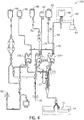
- Figs. 2-4 depict a separator 10 with fluid circuit 200 mounted thereon ( Fig. 2 ), the fluid circuit ( Fig. 4 ) having a blood processing container 14 ( Fig. 3 ) defining a separation chamber 12 suitable for harvesting mononuclear cells (MNC) from whole blood.
- a disposable processing set or fluid circuit 200 (which includes container 14) may be mounted on the front panel of separator 10.
- the fluid circuit 200 may include a plurality of processing cassettes 23L, 23M and 23R with tubing loops for association with peristaltic pumps on separator 10.
- Fluid circuit 200 may also include a network of tubing and pre-connected containers for establishing flow communication with the patient and for processing and collecting fluids and blood and blood components, as shown in Fig. 4 .
- disposable processing set 200 may include a container 60 for supplying anticoagulant, a waste container 62 for collecting waste from one or more steps in the process for treating and washing mononuclear cells, a container 64 for holding saline or other wash or resuspension medium, a container 66 for collecting plasma, a container 68 for collecting the mononuclear cells and, optionally, container 69 for holding the photoactivation agent.
- Container 68 may also serve as the illumination container, and the illumination container 68 may be pre-attached to and integral with the disposable set 200. Alternatively, container 68 may be attached to set 200 by known sterile connection techniques, such as sterile docking or the like.
- container 68 is shown as suspended from device 10. However, container 68 may be housed within an adjacent separately housed irradiation device 20 (as shown by broken lines in Fig. 4 ), thereby eliminating the step of having the operator place container 68 into irradiation device 20.
- the tubing leading to and/or from container 68 in fluid circuit 200 may be of a sufficient length to reach an irradiation device 20 that is adjacent to but housed separately from the separation device.
- fluid circuit 200 may include inlet line 72, an anticoagulant (AC) line 74 for delivering AC from container 60, an RBC line 76 for conveying red blood cells from chamber 12 of container 14 to container 67, a platelet poor plasma (PPP) line 78 for conveying PPP to container 66 and line 80 for conveying mononuclear cells to and from blood processing container 14 and collection/illumination container 68.
- the blood processing set may include one or more venipuncture needle(s) for accessing the circulatory system of the patient.
- fluid circuit 200 may include inlet needle 70 and return needle 82. In an alternative embodiment, a single needle may serve as both the inlet and outlet needle.
- Fluid flow through fluid circuit 200 may be driven, controlled and adjusted by a microprocessor-based controller in cooperation with the valves, pumps, weight scales and sensors of device 10 and fluid circuit 200, the details of which are described in the aforementioned U.S. Pat. No. 6,027,657 , although any suitable controller may be used.
- the fluid circuit may be further adapted for association with the irradiation device 20.
- a suitable irradiation device is described in U.S. Pat. No. 7,433,030 , which is incorporated by reference herein in its entirety, although any irradiation device may be used.
- the irradiation device 20 may include a tray or other holder for receiving one or more containers during treatment.
- Fig. 5 depicts one embodiment of an online method of treating mononuclear cells.
- An "online" photopheresis system includes both the blood separation device and the irradiation device in an integrated system.
- An online system provides for reinfusion of treated target cells back to the patient.
- Whole blood may first be withdrawn from a patient (step 30) through inlet needle 70 and introduced into the separation chamber 12 of container 14 of processing set 200, where the whole blood is subjected to, for example, a centrifugal field.
- the centrifugal field may separate the target cell population, i.e., mononuclear cells, from red blood cells, platelets and plasma (step 32).
- the components such as red blood cells and platelets may be returned to the patient or may be diverted to a container (e.g., container 67) for further processing.
- Collection of the mononuclear cells may proceed in one or more cycles, with the number of processing cycles conducted in a given therapeutic procedure depending upon the total volume of MNCs to be collected.
- Fig. 5 depicts an online method of treating MNCs, offline methods are available as well.
- an apheresis device may be used to collect target cells.
- the collected target cells typically contained in one or more collection containers, are severed or otherwise separated from the tubing set used during collection, where they are later treated in a separate irradiation or UV light device followed by subsequent reinfusion of the treated cells to a patient.
- the irradiation device which device may be located in another room or laboratory
- Collected target cells may be concentrated, diluted, or otherwise processed in preparation for irradiation within collection/illumination container 68 ( Fig. 4 ).
- collected target cells may be diluted with plasma and/or saline, e.g., at step 33 of Fig. 5 , to achieve a desired hematocrit.
- Collected target cells may also be combined with a suitable photoactivation agent, e.g., step 34 of Fig. 5 , in preparation for irradiation.
- Fig. 6 shows an illumination container comprising features useful for labeling, tracking, and/or authenticating disposable components, according to an exemplary embodiment.
- illumination container 68 that is part of disposable circuit 200 of Fig. 4 may comprise a tag 57 and/or a code 56 useful in preventing damage, alteration, falsification, and/or reuse of container 68 and/or any part of disposable circuit 200. Incorporating the tag 57 and/or code 56 onto container 68 may also prevent use of an otherwise legitimate disposable circuit intended for a different procedure performed by the system 5, separation component 10, and/or treatment component 20 ( Fig. 1 ).
- the system 5 may be programmed with a variety of other procedures, e.g., MNC collection (without photopheresis), platelet collection, offline photopheresis, etc., with each procedure having a corresponding and different disposable circuit.
- MNC collection without photopheresis
- platelet collection offline photopheresis
- offline photopheresis etc.
- a user may be prevented from attempting to perform the online photopheresis procedure with a disposable circuit meant for, e.g., MNC collection, by scanning for the tag 57 and/or code 56 on container 68 to verify correctness of procedure and disposable circuit.
- Tag 57 and/or code 56 may preferably maintain structural integrity during any storage period of container 68 and may preferably be covert as to attract minimal notice from users.
- code may be understood as an identification feature that provides relatively high labeling capacity or serialization.
- a code may contain information decodable by a computer that may recognize a product and its details by cross-checking with established reference codes in a database.
- tag may be understood as an identification feature that provides limited labeling capacity and may be recognized by a computer but not decodable with information by the computer.
- a tag may be used for simple authentication and/or tracking but may contain minimal information regarding the specific product.
- various molecules with characteristic optical emission may be used for the tag 57 and/or code 56 of container 68.
- a molecule with characteristic optical emission may be described as a molecule that is excited and isomerized by light close to certain wavelengths and will back-isomerize and generate emission at another wavelength when the excitation light is removed.
- a molecule that is isomerized by UV light and emits light at a non-UV wavelength when it is back-isomerized may be used.
- UV-isomerized molecules with back-isomerization resulting in characteristic non-UV emission in the visible spectrum is photochromic ink.
- various coumarin derivatives may isomerize in UV light and back-isomerize to emit green/yellow light having wavelengths in the range of 500-580 nm.
- Such coumarin derivatives include Coumarin 7 and Coumarin 30.
- colorless diarylethene derivatives incorporating trimethylsilyl (TMS) groups may isomerize in UV light, back-isomerize to emit blue light having wavelengths in the range of 455 to 492 nm, and in the presence of visible light, return to its colorless isomer.
- Another embodiment may incorporate a molecule that is isomerized by UV light and emits light at near-infrared wavelengths when back-isomerized. Infrared emission may be desirable when it is intended for a tag/code to be invisible to the naked eye.
- molecules that are isomerized by UV light and emit light at infrared or near-infrared wavelengths of 700-850 nm when back-isomerized include various organic dyes, e.g., cyanine, oxazine, and rhodamine, and inorganic dyes, such as lanthanide-emitters.
- Another embodiment may incorporate different types of molecules with characteristic emission to create a unique fingerprint that is difficult to detect, ascertain, and/or replicate.
- a select molecule or combination of molecules with characteristic optical emission may be dissolved in a solvent or ink suitable for printing on a medical device disposable component, such as container 68 ( Fig. 4 ).
- a printable ink is the photochromic textile screen ink available through QCR Solutions, Corp., although any suitable ink for medical devices may be used.
- a design, code, or pattern (“identifiable feature") formed by the photo-identifiable entity may be sensed, recognized, and/or decoded during irradiation or otherwise during a period in which the photo-identifiable entity is emitting photons.
- the substrate upon which the identifiable feature may be printed may be an inner or outer surface of the container 68.
- Fig. 7 shows a side view of container 68, according to an exemplary embodiment.
- container 68 comprising container walls 92 may be made of a single layer of a polymer material, such as PVC or non-PVC polymer or polymer blend. In such a case, the identifiable feature may be printed or attached directly on the wall 92 of container 68.
- container wall 92 may be made of a multiple sheet laminate wherein an inner layer 13 is made of one material and outer layer 17 is made of a different material.
- the substrate upon which the identifiable feature may be printed may be separate from inner layer 13 and outer layer 17 and be placed between layers and form a part of the container wall 92.
- the identifiable feature may be printed on outer surface 17a of outer layer 17, inner surface 17b of outer layer 17, outer layer 13a of inner layer 13, and/or inner surface 13b of inner layer 13.
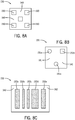
- Figs. 8A-8C show several examples of identifiable features.
- Fig. 8A shows an identifiable feature 130 comprising a substrate 140 upon which a photo-identifiable entity may be printed.
- Select areas 150 of the substrate 140 may comprise one photo-identifiable entity and the background 160 another photo-identifiable entity or no photo-identifiable entity.
- areas 150 may be printed with a photo-identifiable entity comprising a compound that is isomerized by UV light and emits light at near-infrared wavelengths when back-isomerized, e.g., a lanthanide-emitter, while the background 160 comprises substrate 140 without any photo-identifiable entity.
- Fig. 8A shows an identifiable feature 130 comprising a substrate 140 upon which a photo-identifiable entity may be printed.
- Select areas 150 of the substrate 140 may comprise one photo-identifiable entity and the background 160 another photo-identifiable entity or no photo-identifiable entity.
- areas 150 may
- FIG. 8B shows an identifiable feature 131 comprising a substrate 141 upon which a plurality of photo-identifiable entities may be printed.
- Select areas 151 a of the substrate 141 may comprise one photo-identifiable entity, select areas 151b a second photo-identifiable entity, and the background 161 a third photo-identifiable entity.
- areas 151 a may be printed with a photo-identifiable entity comprising a compound that is isomerized by UV light and emits yellow/green wavelength light when back-isomerized, e.g., a coumarin derivative
- areas 151b are printed with a photo-identifiable entity comprising a compound that is isomerized by UV light and emits blue wavelength light when back-isomerized, e.g., a TMS-incorporated diarylethene derivative
- the background 161 comprises substrate 141 without any photo-identifiable entity.
- Fig. 8C shows an identifiable feature 132 in the form of a barcode.
- Feature 132 may comprise bars 152a-152e that together contains coded information.
- Feature 132 may comprise a substrate 142 upon which bars 152a-152e having one or more photo-identifiable entities may be printed. In one embodiment, all bars 152a-152e may have the same photo-identifiable entity. In another embodiment, a specific combination and/or spatial arrangement of a plurality of photo-identifiable entities forming bars 152a-152e may form the barcode.
- Fig. 8C has been described as a barcode, it should be understood that the displayed code may be any suitable identifiable code, such as a QR code.
- an identification feature exhibiting expiration may be incorporated into an illumination container or any medical device disposable component to prevent reuse of the authentic component.
- the identification feature may comprise a curable resin/adhesive that is irreversibly cured by an excitation light source, e.g., UV light.
- a curable resin/adhesive prior to exposure to an excitation light source may be in an unlinked polymer state and emit/reflect/transmit one specific wavelength or set of wavelengths of light.
- the resin/adhesive may become cross-linked and emit/reflect/transmit a second specific wavelength or set of wavelengths of light.
- resin/adhesives that comprise one absorption spectra pattern prior to curing and another absorption spectra pattern during and/or after curing are various See-Cure products available from Dymax Corporation.
- the curable resin/adhesive may be covered until time of use of the disposable component.
- a disposable component incorporating curable resin/adhesive may be checked by a sensor or scanner to confirm that the resin/adhesive is in an uncured state prior to authorizing an irradiation procedure.
- the curable resin/adhesive may be used in combination with various embodiments of the photo-identifiable entities described above to result in a disposable component that is simultaneously difficult to replicate and re-use.
- a curable resin/adhesive may be incorporated into the barcode of Fig. 8C by overlaying the resin with one or more bars 152a-152e and/or adding bar(s) comprising curable resin.
- the barcode of Fig. 8C may emit/transmit a pattern of wavelengths of light differently when the resin is uncured versus when the resin is cured.
- an irradiation device incorporating a sensor and a computer may first irradiate and scan prior to continuing the irradiation procedure to confirm that the received wavelengths of light and/or pattern of wavelengths of light initially includes blue light in addition to the pattern of photo-identifiable entities recognized by the device to approve and/or allow it to proceed with the procedure.
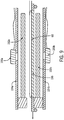
- Fig. 9 shows a cross-sectional view of the irradiation component 20 of Fig. 1 holding container 68 having a tag 57 and/or code 56 ( Fig. 6 ) and containing a target cell product.
- One or more irradiation receivers (e.g., sensors) 100a sensitive to a specific set of wavelengths, may be mounted above an upper bank 102a of a plurality of irradiation transmitters (e.g., UV light bulbs).
- a reflector plate 104a may be disposed above the upper bank 102a of light bulbs to reflect light emitted by the bulbs.
- An exposure plane 106 comprised of material transparent to the specific range of wavelengths emitted by the upper bank 102a (e.g., UV-transparent material) may be disposed below the upper bank 102a of light bulbs to support illumination container 68.
- a lower bank 102b of a plurality of irradiation transmitters, e.g., UV light bulbs, may be disposed below the exposure plane 106.
- a second reflector plate 104b may be disposed below the lower bank 102b of irradiation transmitters to reflect light emitted by the light bulbs.
- One or more irradiation receivers (e.g., sensors) 100b, sensitive to the same or different range of wavelengths as receivers 100a, may be mounted below the lower bank 102b of the light bulbs.
- the irradiation device 20 may include any number of irradiation receivers 100a, 100b, depending on the number and sophistication of the tags 57 and/or codes 56, and the irradiation receivers 100a, 100b, may be tuned via filters to exclude frequencies of light other than the specific frequencies of light emitted/transmitted by the tags 57/codes 56, to minimize light interference.
- the one or more irradiation receivers 100a, 100b may comprise image sensors capable of mapping wavelength emissions/transmittance in 1D or 2D space.
- CMOS and CCD sensors are examples of image sensors comprising a two-dimensional grid.
- Diodes sensitive to UV and/or infrared light outside the visible spectrum may be incorporated into the receivers 100a, 100b in an embodiment in which UV and IR wavelengths are to be recognized.
- the irradiation device may be configured to commence or proceed with irradiation when irradiation receivers 100a, 100b detect a recognized identifiable feature matching specific spatial, wavelength, intensity, and/or temporal characteristics.
- a computer-implemented method for approving a medical device disposable component used in a medical procedure includes providing an identifiable feature on a medical device disposable component.
- the identifiable feature comprises one or more photo-identifiable entities having a first emission pattern when in an unexcited state and a second emission pattern when in an excited state.
- the identifiable feature is illuminated with an excitation light source to elicit the second emission pattern.
- the second emission pattern is detected and compared against a set of established reference emission patterns. Based on comparison of the second emission pattern to the set of established reference emission patterns, it is determined whether the medical device disposable component is approved.
- the medical procedure is continued if the second emission pattern is a match with the set of established reference emission patterns.
- the first emission pattern is detected and it is determined whether the medical device disposable component is approved based on comparison of the first emission pattern to a second set of established reference emission patterns.
- a transformation from an unexcited state to an excited state for at least one photo-identifiable entity is irreversible.
- detecting the second emission pattern comprises detecting at least one of wavelength range, two-dimensional location of wavelength emission, wavelength intensity, wavelength spatial sequence, and wavelength temporal sequence.
- the one or more photo-identifiable entities comprises at least one of photochromic ink and curable adhesive.
- a substrate is provided upon which one or more photo-identifiable entities are printed.
- the substrate is embedded within the medical device disposable component between a first layer and a second layer of a material of the disposable component.
- the second emission pattern is detected by irradiation receivers comprising at least one of CMOS and CCD image sensors.
- the excitation light source comprises UV light and the emission pattern comprises infrared light.
- a medical device authentication and authorization system during a medical procedure.
- the system includes a durable medical device comprising an excitation light source and at least one irradiation receiver.
- a fluid circuit is configured to cooperatively associate with the durable medical device.
- the fluid circuit comprises a disposable component having an identifiable feature comprising one or more photo-identifiable entities having a first emission pattern when in an unexcited state and a second emission pattern when in an excited state.
- the system also includes a programmable controller.
- the programmable controller is configured to illuminate the identifiable feature with the excitation light source to elicit the second emission pattern, detect the second emission pattern with the at least one irradiation receiver, compare the second emission pattern against a set of established reference emission patterns, and determine whether the disposable component is approved based on comparison of the second emission pattern to the set of established reference emission patterns.
- the programmable controller is further configured to proceed with the medical procedure if the second emission pattern is a match with the set of established reference emission patterns.
- the programmable controller is further configured to detect the first emission pattern and determine whether the disposable component is approved based on comparison of the first emission pattern to a second set of established reference emission patterns.
- a transformation from an unexcited state to an excited state for at least one photo-identifiable entity is irreversible.
- the programmable controller comparing the second emission pattern against the set of established reference emission patterns comprises comparing at least one of wavelength range, two-dimensional location of wavelength emission, wavelength intensity, wavelength spatial sequence, and wavelength temporal sequence.
- the one or more photo-identifiable entities comprises at least one of photochromic ink and curable adhesive.
- the first and second emission patterns for at least one photo-identifiable entity do not comprise visible light.
- the disposable component comprises a first and second layer of one or more disposable component materials.
- a substrate upon which the one or more photo-identifiable entities are printed is disposed between the first and second layer.
- the irradiation receiver comprises at least one of CMOS and CCD image sensors.
- the excitation light source comprises UV light and the second emission pattern comprises infrared light.
Landscapes
- Health & Medical Sciences (AREA)
- Engineering & Computer Science (AREA)
- Heart & Thoracic Surgery (AREA)
- Vascular Medicine (AREA)
- Biomedical Technology (AREA)
- General Health & Medical Sciences (AREA)
- Public Health (AREA)
- Anesthesiology (AREA)
- Life Sciences & Earth Sciences (AREA)
- Animal Behavior & Ethology (AREA)
- Hematology (AREA)
- Veterinary Medicine (AREA)
- Cardiology (AREA)
- General Business, Economics & Management (AREA)
- Business, Economics & Management (AREA)
- Epidemiology (AREA)
- Medical Informatics (AREA)
- Primary Health Care (AREA)
- Nuclear Medicine, Radiotherapy & Molecular Imaging (AREA)
- Surgery (AREA)
- Urology & Nephrology (AREA)
- Apparatus For Disinfection Or Sterilisation (AREA)
Abstract
Description
- This application claims the benefit of
U.S. Provisional Patent App. No. 62/526,784 filed June 29, 2017 - The present disclosure relates generally to methods, systems, and apparatus to authorize a medical device instrument and, in particular, to methods, systems, and apparatus to authenticate usage of a disposable component in a medical device instrument with UV irradiation.
- Light irradiation therapy may be used for the treatment of various blood diseases to, e.g., eliminate immunogenicity in cells, inactivate or kill selected cells, inactivate viruses or bacteria, and/or activate desirable immune responses. For example, the photoactivatable drug psoralen may be used to treat pathogenic blood cells, such as lymphocytes, in an extracorporeal photopherisis (ECP) procedure in which the patient receives 8-methoxypsoralen (8-MOP), blood is withdrawn from the patient, the white cells separated (typically by centrifugation), and subjected to UV light to activate the 8-MOP molecules. The photoactivated 8-MOP may alter the DNA of the pathogenic leukocytes, and the fluid with the altered leukocytes may be reinfused back into the patient to induce an immune system response.
- Light irradiation therapy may be performed by a medical device instrument, such as an apheresis instrument. An apheresis instrument may be used to separate blood components from whole blood by passing blood of a donor/patient through the instrument to separate one or more blood components from the whole blood. The remainder of the whole blood may be returned to the circulatory system of the donor/patient and/or collected.
- The medical device instrument may utilize a centrifuge and/or membrane separator to separate blood components. A disposable component may be connected to the instrument for collection of a desired blood component. The instrument hardware may have pumps, clamps, and valves that move and direct fluid or blood through the disposable component. Part of the disposable component may include a bag into which the desired blood component is collected for light irradiation therapy.
- According to an exemplary embodiment, the present disclosure is directed to a computer-implemented method for approving a medical device disposable component used in a medical procedure comprising providing an identifiable feature on a medical device disposable component, wherein the identifiable feature comprises one or more photo-identifiable entities having a first emission pattern when in an unexcited state and a second emission pattern when in an excited state. The method also comprises illuminating the identifiable feature with an excitation light source to elicit the second emission pattern, detecting the second emission pattern and comparing the second emission pattern against a set of established reference emission patterns, and determining whether the medical device disposable component is approved based on comparison of the second emission pattern to the set of established reference emission patterns.
- According to an exemplary embodiment, the present disclosure is directed to a medical device authentication and authorization system during a medical procedure comprising a durable medical device comprising an excitation light source and at least one irradiation receiver. The system also comprises a fluid circuit configured to cooperatively associate with the durable medical device, the fluid circuit comprising a disposable component having an identifiable feature comprising one or more photo-identifiable entities having a first emission pattern when in an unexcited state and a second emission pattern when in an excited state. The system also comprises a programmable controller configured to illuminate the identifiable feature with the excitation light source to elicit the second emission pattern, detect the second emission pattern with the at least one irradiation receiver, compare the second emission pattern against a set of established reference emission patterns, and determine whether the disposable component is approved based on comparison of the second emission pattern to the set of established reference emission patterns.
- Features, aspects, and advantages of the present embodiments will become apparent from the following description, appended claims, and the accompanying exemplary embodiments shown in the drawings, which are briefly described below.
-
Fig. 1 is a diagram generally showing the mechanical components of a photopheresis treatment device, according to an exemplary embodiment; -
Fig. 2 is a partial perspective view of an apheresis separator useful in the methods and systems described herein, according to an exemplary embodiment; -
Fig. 3 is a perspective view of a separation chamber of the processing set used with the separator ofFig. 2 , according to an exemplary embodiment; -
Fig. 4 is a diagram of the fluid circuit useful in the collection, treatment and reinfusion of target cells, according to an exemplary embodiment; -
Fig. 5 is a flow chart setting forth a portion of the steps of the method of a photopheresis treatment, according to an exemplary embodiment; -
Fig. 6 shows an illumination container comprising features useful for labeling, tracking, and/or authenticating disposable components, according to an exemplary embodiment; -
Fig. 7 shows a side view of the illumination container ofFig. 6 , according to an exemplary embodiment; -
Figs. 8A-8C show identifiable features detectable and recognizable by an authentication system, according to an exemplary embodiment; and -
Fig. 9 is a cross-sectional view of the irradiation component ofFig. 1 holding an illumination container, according to an exemplary embodiment. - There are several aspects of the present subject matter which may be embodied separately or together in the devices and systems described and claimed below. These aspects may be employed alone or in combination with other aspects of the subject matter described herein, and the description of these aspects together is not intended to preclude the use of these aspects separately or the claiming of such aspects separately or in different combinations as set forth in the claims appended hereto.
- Some embodiments may prevent use of counterfeit, already-used, and/or repurposed disposable components.
- Some embodiments may prevent instrument use in an unintended manner, e.g., online use versus offline use.
- Some embodiments may enable instrument and/or disposable component authentication with minimal user knowledge.
- Some embodiments may increase difficulty in replicating authenticity markers and thereby improve copycat protection for disposable components.
- Some embodiments may increase longevity of authenticity markers of disposable components.
- Some embodiments may obviate a dedicated light source for scanning and/or authentication purposes.
-
Fig. 1 shows, in general, the mechanical components that make up anECP system 5 and that may be used in one or more of the methods described herein. Thesystem 5 may include aseparation component 10 and a treatment (i.e., irradiation)component 20.Irradiation component 20 may be independent and housed separately from theseparation component 10, orcomponents components separation device 10 andirradiation device 20 may be located adjacent to each other, allowing an operator or clinician to have access to both devices during a particular treatment procedure. A patient may be connected to afluid circuit 200 as shown inFigs. 1 ,2 ,4 that provides a sterile closed pathway betweenseparation component 10 andirradiation component 20 and may be cooperatively mounted on the hardware of theseparation device 10. Theseparation device 10 may have one or more features of an apheresis device, such as those described in greater detail inU.S. Patent Nos. 5,868,696 and6,027,657 , and PCT Patent Application No.PCT/US2012/28492 , which are hereby incorporated herein by reference in their entireties, although any suitable separation device may be used. Although the embodiments disclosed herein are described in conjunction with aseparation device 10, the present embodiments may be applicable to anirradiation device 20 alone, in which case the target cell population may be provided to theirradiation device 20 subsequent to being collected elsewhere. While improved authorization/authentication systems and methods will be described herein with reference to apheresis and photopheresis, it should be understood that these principles may be employed with other medical procedures involving a specific range of light frequencies without departing from the scope of the present disclosure. - With reference to
Fig. 1 , whole blood may be withdrawn from the patient and introduced into theseparation component 10 where the whole blood is separated to provide a target cell population. In one embodiment, the target cell population may be mononuclear cells (MNCs) or MNCs of a particular type (lymphocytes, monocytes, and/or dendritic cells, etc.). Other components separated from the whole blood, such as red blood cells (RBCs), plasma, and/or platelets may be returned to the patient or collected in pre-attached containers of the blood processing set. - The separated target cell population, e.g., mononuclear cells, may then be treated and irradiated in
treatment component 20. As discussed above, treatment of mononuclear cells may involve the photoactivation of a photoactive agent that has been combined with the mononuclear cells. Mononuclear cells may be collected using a device described in greater detail in the aforementionedUS. Pat. No. 6,027,657 . The apparatus used for the harvesting, collection and reinfusion of mononuclear cells may be a "multifunctional" automated apheresis device, as is the case with that described inUS. Pat. No. 6,027,657 . In other words, theseparation component 10 may be a multifunctional automated apparatus that can perform various collection protocols and/or serve multiple purposes, as may be needed by a particular hospital or facility, such that it can be used not only in the systems and methods for performing photopheresis treatment of MNC as described herein, but can also be used for other purposes including the collection of blood and blood components including platelets, plasma, red blood cells, granulocytes and/or perform plasma/RBC exchange, among other functions required by a hospital or medical facility. -
Figs. 2-4 depict aseparator 10 withfluid circuit 200 mounted thereon (Fig. 2 ), the fluid circuit (Fig. 4 ) having a blood processing container 14 (Fig. 3 ) defining aseparation chamber 12 suitable for harvesting mononuclear cells (MNC) from whole blood. As shown inFig. 2 , a disposable processing set or fluid circuit 200 (which includes container 14) may be mounted on the front panel ofseparator 10. Thefluid circuit 200 may include a plurality ofprocessing cassettes separator 10.Fluid circuit 200 may also include a network of tubing and pre-connected containers for establishing flow communication with the patient and for processing and collecting fluids and blood and blood components, as shown inFig. 4 . As seen inFigs. 2 and4 , disposable processing set 200 may include acontainer 60 for supplying anticoagulant, awaste container 62 for collecting waste from one or more steps in the process for treating and washing mononuclear cells, acontainer 64 for holding saline or other wash or resuspension medium, acontainer 66 for collecting plasma, acontainer 68 for collecting the mononuclear cells and, optionally,container 69 for holding the photoactivation agent. -
Container 68 may also serve as the illumination container, and theillumination container 68 may be pre-attached to and integral with thedisposable set 200. Alternatively,container 68 may be attached to set 200 by known sterile connection techniques, such as sterile docking or the like. InFig. 2 ,container 68 is shown as suspended fromdevice 10. However,container 68 may be housed within an adjacent separately housed irradiation device 20 (as shown by broken lines inFig. 4 ), thereby eliminating the step of having theoperator place container 68 intoirradiation device 20. The tubing leading to and/or fromcontainer 68 influid circuit 200 may be of a sufficient length to reach anirradiation device 20 that is adjacent to but housed separately from the separation device. - With reference to
Fig. 4 ,fluid circuit 200 may includeinlet line 72, an anticoagulant (AC)line 74 for delivering AC fromcontainer 60, anRBC line 76 for conveying red blood cells fromchamber 12 ofcontainer 14 tocontainer 67, a platelet poor plasma (PPP)line 78 for conveying PPP tocontainer 66 andline 80 for conveying mononuclear cells to and fromblood processing container 14 and collection/illumination container 68. The blood processing set may include one or more venipuncture needle(s) for accessing the circulatory system of the patient. As shown inFig. 4 ,fluid circuit 200 may includeinlet needle 70 and returnneedle 82. In an alternative embodiment, a single needle may serve as both the inlet and outlet needle. - Fluid flow through
fluid circuit 200 may be driven, controlled and adjusted by a microprocessor-based controller in cooperation with the valves, pumps, weight scales and sensors ofdevice 10 andfluid circuit 200, the details of which are described in the aforementionedU.S. Pat. No. 6,027,657 , although any suitable controller may be used. - In accordance with the present disclosure, the fluid circuit may be further adapted for association with the
irradiation device 20. One example of a suitable irradiation device is described inU.S. Pat. No. 7,433,030 , which is incorporated by reference herein in its entirety, although any irradiation device may be used. Theirradiation device 20 may include a tray or other holder for receiving one or more containers during treatment. -
Fig. 5 depicts one embodiment of an online method of treating mononuclear cells. An "online" photopheresis system includes both the blood separation device and the irradiation device in an integrated system. An online system provides for reinfusion of treated target cells back to the patient. Whole blood may first be withdrawn from a patient (step 30) throughinlet needle 70 and introduced into theseparation chamber 12 ofcontainer 14 of processing set 200, where the whole blood is subjected to, for example, a centrifugal field. The centrifugal field may separate the target cell population, i.e., mononuclear cells, from red blood cells, platelets and plasma (step 32). The components such as red blood cells and platelets may be returned to the patient or may be diverted to a container (e.g., container 67) for further processing. Collection of the mononuclear cells may proceed in one or more cycles, with the number of processing cycles conducted in a given therapeutic procedure depending upon the total volume of MNCs to be collected. AlthoughFig. 5 depicts an online method of treating MNCs, offline methods are available as well. In offline methods, an apheresis device may be used to collect target cells. The collected target cells, typically contained in one or more collection containers, are severed or otherwise separated from the tubing set used during collection, where they are later treated in a separate irradiation or UV light device followed by subsequent reinfusion of the treated cells to a patient. During such offline methods, when the cells are transferred from the apheresis device to the irradiation device (which device may be located in another room or laboratory), communication with the patient is severed and the cells detached from the patient. - Collected target cells may be concentrated, diluted, or otherwise processed in preparation for irradiation within collection/illumination container 68 (
Fig. 4 ). For example, collected target cells may be diluted with plasma and/or saline, e.g., atstep 33 ofFig. 5 , to achieve a desired hematocrit. Collected target cells may also be combined with a suitable photoactivation agent, e.g., step 34 ofFig. 5 , in preparation for irradiation. -
Fig. 6 shows an illumination container comprising features useful for labeling, tracking, and/or authenticating disposable components, according to an exemplary embodiment. In one embodiment,illumination container 68 that is part ofdisposable circuit 200 ofFig. 4 may comprise atag 57 and/or acode 56 useful in preventing damage, alteration, falsification, and/or reuse ofcontainer 68 and/or any part ofdisposable circuit 200. Incorporating thetag 57 and/orcode 56 ontocontainer 68 may also prevent use of an otherwise legitimate disposable circuit intended for a different procedure performed by thesystem 5,separation component 10, and/or treatment component 20 (Fig. 1 ). For example, thesystem 5 may be programmed with a variety of other procedures, e.g., MNC collection (without photopheresis), platelet collection, offline photopheresis, etc., with each procedure having a corresponding and different disposable circuit. In an embodiment in which an authentication protocol is initiated for, e.g., an online photopheresis procedure, a user may be prevented from attempting to perform the online photopheresis procedure with a disposable circuit meant for, e.g., MNC collection, by scanning for thetag 57 and/orcode 56 oncontainer 68 to verify correctness of procedure and disposable circuit. -
Tag 57 and/orcode 56 may preferably maintain structural integrity during any storage period ofcontainer 68 and may preferably be covert as to attract minimal notice from users. The term "code" may be understood as an identification feature that provides relatively high labeling capacity or serialization. For example, a code may contain information decodable by a computer that may recognize a product and its details by cross-checking with established reference codes in a database. The term "tag" may be understood as an identification feature that provides limited labeling capacity and may be recognized by a computer but not decodable with information by the computer. For example, a tag may be used for simple authentication and/or tracking but may contain minimal information regarding the specific product. - In one embodiment, various molecules with characteristic optical emission may be used for the
tag 57 and/orcode 56 ofcontainer 68. A molecule with characteristic optical emission may be described as a molecule that is excited and isomerized by light close to certain wavelengths and will back-isomerize and generate emission at another wavelength when the excitation light is removed. For example, in an embodiment in which UV light is used to irradiatecontainer 68 and its contents, a molecule that is isomerized by UV light and emits light at a non-UV wavelength when it is back-isomerized may be used. One example of UV-isomerized molecules with back-isomerization resulting in characteristic non-UV emission in the visible spectrum is photochromic ink. For example, various coumarin derivatives may isomerize in UV light and back-isomerize to emit green/yellow light having wavelengths in the range of 500-580 nm. Such coumarin derivatives include Coumarin 7 andCoumarin 30. In another example, colorless diarylethene derivatives incorporating trimethylsilyl (TMS) groups may isomerize in UV light, back-isomerize to emit blue light having wavelengths in the range of 455 to 492 nm, and in the presence of visible light, return to its colorless isomer. - Another embodiment may incorporate a molecule that is isomerized by UV light and emits light at near-infrared wavelengths when back-isomerized. Infrared emission may be desirable when it is intended for a tag/code to be invisible to the naked eye. Examples of molecules that are isomerized by UV light and emit light at infrared or near-infrared wavelengths of 700-850 nm when back-isomerized include various organic dyes, e.g., cyanine, oxazine, and rhodamine, and inorganic dyes, such as lanthanide-emitters. Another embodiment may incorporate different types of molecules with characteristic emission to create a unique fingerprint that is difficult to detect, ascertain, and/or replicate.
- A select molecule or combination of molecules with characteristic optical emission (hereinafter "photo-identifiable entity") may be dissolved in a solvent or ink suitable for printing on a medical device disposable component, such as container 68 (
Fig. 4 ). An example of a printable ink is the photochromic textile screen ink available through QCR Solutions, Corp., although any suitable ink for medical devices may be used. A design, code, or pattern ("identifiable feature") formed by the photo-identifiable entity may be sensed, recognized, and/or decoded during irradiation or otherwise during a period in which the photo-identifiable entity is emitting photons. In an embodiment in which the disposable component to be tagged/coded is a fluid container such as thecontainer 68 ofFig. 4 , the substrate upon which the identifiable feature may be printed may be an inner or outer surface of thecontainer 68.Fig. 7 shows a side view ofcontainer 68, according to an exemplary embodiment. In one embodiment,container 68 comprisingcontainer walls 92 may be made of a single layer of a polymer material, such as PVC or non-PVC polymer or polymer blend. In such a case, the identifiable feature may be printed or attached directly on thewall 92 ofcontainer 68. In another embodiment,container wall 92 may be made of a multiple sheet laminate wherein aninner layer 13 is made of one material andouter layer 17 is made of a different material. In such a case, the substrate upon which the identifiable feature may be printed may be separate frominner layer 13 andouter layer 17 and be placed between layers and form a part of thecontainer wall 92. In another multi-layer embodiment, the identifiable feature may be printed onouter surface 17a ofouter layer 17,inner surface 17b ofouter layer 17,outer layer 13a ofinner layer 13, and/orinner surface 13b ofinner layer 13. -
Figs. 8A-8C show several examples of identifiable features.Fig. 8A shows anidentifiable feature 130 comprising asubstrate 140 upon which a photo-identifiable entity may be printed.Select areas 150 of thesubstrate 140 may comprise one photo-identifiable entity and thebackground 160 another photo-identifiable entity or no photo-identifiable entity. For example,areas 150 may be printed with a photo-identifiable entity comprising a compound that is isomerized by UV light and emits light at near-infrared wavelengths when back-isomerized, e.g., a lanthanide-emitter, while thebackground 160 comprisessubstrate 140 without any photo-identifiable entity.Fig. 8B shows anidentifiable feature 131 comprising asubstrate 141 upon which a plurality of photo-identifiable entities may be printed.Select areas 151 a of thesubstrate 141 may comprise one photo-identifiable entity,select areas 151b a second photo-identifiable entity, and the background 161 a third photo-identifiable entity. For example,areas 151 a may be printed with a photo-identifiable entity comprising a compound that is isomerized by UV light and emits yellow/green wavelength light when back-isomerized, e.g., a coumarin derivative, whileareas 151b are printed with a photo-identifiable entity comprising a compound that is isomerized by UV light and emits blue wavelength light when back-isomerized, e.g., a TMS-incorporated diarylethene derivative, while thebackground 161 comprisessubstrate 141 without any photo-identifiable entity.Fig. 8C shows anidentifiable feature 132 in the form of a barcode. Feature 132 may comprisebars 152a-152e that together contains coded information. Feature 132 may comprise asubstrate 142 upon which bars 152a-152e having one or more photo-identifiable entities may be printed. In one embodiment, allbars 152a-152e may have the same photo-identifiable entity. In another embodiment, a specific combination and/or spatial arrangement of a plurality of photo-identifiableentities forming bars 152a-152e may form the barcode. AlthoughFig. 8C has been described as a barcode, it should be understood that the displayed code may be any suitable identifiable code, such as a QR code. - In another embodiment, an identification feature exhibiting expiration may be incorporated into an illumination container or any medical device disposable component to prevent reuse of the authentic component. The identification feature may comprise a curable resin/adhesive that is irreversibly cured by an excitation light source, e.g., UV light. A curable resin/adhesive prior to exposure to an excitation light source may be in an unlinked polymer state and emit/reflect/transmit one specific wavelength or set of wavelengths of light. In response to exposure to the excitation light source or shortly thereafter, the resin/adhesive may become cross-linked and emit/reflect/transmit a second specific wavelength or set of wavelengths of light. Examples of resin/adhesives that comprise one absorption spectra pattern prior to curing and another absorption spectra pattern during and/or after curing are various See-Cure products available from Dymax Corporation. To prevent accidental exposure to excitation light prior to use, the curable resin/adhesive may be covered until time of use of the disposable component. A disposable component incorporating curable resin/adhesive may be checked by a sensor or scanner to confirm that the resin/adhesive is in an uncured state prior to authorizing an irradiation procedure.
- The curable resin/adhesive may be used in combination with various embodiments of the photo-identifiable entities described above to result in a disposable component that is simultaneously difficult to replicate and re-use. For example, a curable resin/adhesive may be incorporated into the barcode of
Fig. 8C by overlaying the resin with one ormore bars 152a-152e and/or adding bar(s) comprising curable resin. The barcode ofFig. 8C may emit/transmit a pattern of wavelengths of light differently when the resin is uncured versus when the resin is cured. For example, in an embodiment in which uncured resin is blue and cured resin is colorless, an irradiation device incorporating a sensor and a computer may first irradiate and scan prior to continuing the irradiation procedure to confirm that the received wavelengths of light and/or pattern of wavelengths of light initially includes blue light in addition to the pattern of photo-identifiable entities recognized by the device to approve and/or allow it to proceed with the procedure. -
Fig. 9 shows a cross-sectional view of theirradiation component 20 ofFig. 1 holdingcontainer 68 having atag 57 and/or code 56 (Fig. 6 ) and containing a target cell product. One or more irradiation receivers (e.g., sensors) 100a, sensitive to a specific set of wavelengths, may be mounted above anupper bank 102a of a plurality of irradiation transmitters (e.g., UV light bulbs). Areflector plate 104a may be disposed above theupper bank 102a of light bulbs to reflect light emitted by the bulbs. Anexposure plane 106 comprised of material transparent to the specific range of wavelengths emitted by theupper bank 102a (e.g., UV-transparent material) may be disposed below theupper bank 102a of light bulbs to supportillumination container 68. Alower bank 102b of a plurality of irradiation transmitters, e.g., UV light bulbs, may be disposed below theexposure plane 106. Asecond reflector plate 104b may be disposed below thelower bank 102b of irradiation transmitters to reflect light emitted by the light bulbs. One or more irradiation receivers (e.g., sensors) 100b, sensitive to the same or different range of wavelengths asreceivers 100a, may be mounted below thelower bank 102b of the light bulbs. Theirradiation device 20 may include any number ofirradiation receivers tags 57 and/orcodes 56, and theirradiation receivers tags 57/codes 56, to minimize light interference. - In one embodiment, the one or
more irradiation receivers receivers irradiation receivers - Without limiting the foregoing description, in accordance with a first aspect of the subject matter herein, there is provided a computer-implemented method for approving a medical device disposable component used in a medical procedure. The method includes providing an identifiable feature on a medical device disposable component. The identifiable feature comprises one or more photo-identifiable entities having a first emission pattern when in an unexcited state and a second emission pattern when in an excited state. The identifiable feature is illuminated with an excitation light source to elicit the second emission pattern. The second emission pattern is detected and compared against a set of established reference emission patterns. Based on comparison of the second emission pattern to the set of established reference emission patterns, it is determined whether the medical device disposable component is approved.
- In accordance with a second aspect which may be used or combined with the immediately preceding aspect, the medical procedure is continued if the second emission pattern is a match with the set of established reference emission patterns.
- In accordance with a third aspect which may be used or combined with any of the preceding aspects, the first emission pattern is detected and it is determined whether the medical device disposable component is approved based on comparison of the first emission pattern to a second set of established reference emission patterns.
- In accordance with a fourth aspect which may be used or combined with the immediately preceding aspect, a transformation from an unexcited state to an excited state for at least one photo-identifiable entity is irreversible.
- In accordance with a fifth aspect which may be used or combined with any of the preceding aspects, detecting the second emission pattern comprises detecting at least one of wavelength range, two-dimensional location of wavelength emission, wavelength intensity, wavelength spatial sequence, and wavelength temporal sequence.
- In accordance with a sixth aspect which may be used or combined with any of the preceding aspects, the one or more photo-identifiable entities comprises at least one of photochromic ink and curable adhesive.
- In accordance with an eighth aspect which may be used or combined with any of the preceding aspects, a substrate is provided upon which one or more photo-identifiable entities are printed. The substrate is embedded within the medical device disposable component between a first layer and a second layer of a material of the disposable component.
- In accordance with a ninth aspect which may be used or combined with any of the preceding aspects, the second emission pattern is detected by irradiation receivers comprising at least one of CMOS and CCD image sensors.
- In accordance with a tenth aspect which may be used or combined with any of the preceding aspects, the excitation light source comprises UV light and the emission pattern comprises infrared light.
- In accordance with an eleventh aspect, there is provided a medical device authentication and authorization system during a medical procedure. The system includes a durable medical device comprising an excitation light source and at least one irradiation receiver. A fluid circuit is configured to cooperatively associate with the durable medical device. The fluid circuit comprises a disposable component having an identifiable feature comprising one or more photo-identifiable entities having a first emission pattern when in an unexcited state and a second emission pattern when in an excited state. The system also includes a programmable controller. The programmable controller is configured to illuminate the identifiable feature with the excitation light source to elicit the second emission pattern, detect the second emission pattern with the at least one irradiation receiver, compare the second emission pattern against a set of established reference emission patterns, and determine whether the disposable component is approved based on comparison of the second emission pattern to the set of established reference emission patterns.
- In accordance with a twelfth aspect which may be used or combined with the immediately preceding aspect, the programmable controller is further configured to proceed with the medical procedure if the second emission pattern is a match with the set of established reference emission patterns.
- In accordance with a thirteenth aspect which may be used or combined with the eleventh or twelfth aspect, the programmable controller is further configured to detect the first emission pattern and determine whether the disposable component is approved based on comparison of the first emission pattern to a second set of established reference emission patterns.
- In accordance with a fourteenth aspect which may be used or combined with the immediately preceding aspect, a transformation from an unexcited state to an excited state for at least one photo-identifiable entity is irreversible.
- In accordance with a fifteenth aspect which may be used or combined with any of the eleventh through fourteenth aspects, the programmable controller comparing the second emission pattern against the set of established reference emission patterns comprises comparing at least one of wavelength range, two-dimensional location of wavelength emission, wavelength intensity, wavelength spatial sequence, and wavelength temporal sequence.
- In accordance with a sixteenth aspect which may be used or combined with any of the eleventh through fifteenth aspects, the one or more photo-identifiable entities comprises at least one of photochromic ink and curable adhesive.
- In accordance with a seventeenth aspect which may be used or combined with any of the eleventh through sixteenth aspects, the first and second emission patterns for at least one photo-identifiable entity do not comprise visible light.
- In accordance with an eighteenth aspect which may be used or combined with any of the eleventh through seventeenth aspects, the disposable component comprises a first and second layer of one or more disposable component materials. A substrate upon which the one or more photo-identifiable entities are printed is disposed between the first and second layer.
- In accordance with a nineteenth aspect which may be used or combined with any of the eleventh through eighteenth aspects, the irradiation receiver comprises at least one of CMOS and CCD image sensors.
- In accordance with a twentieth aspect which may be used or combined with any of the eleventh through nineteenth aspects, the excitation light source comprises UV light and the second emission pattern comprises infrared light.
- The embodiments disclosed herein are for the purpose of providing a description of the present subject matter, and it is understood that the subject matter may be embodied in various other forms and combinations not shown in detail. Therefore, specific embodiments and features disclosed herein are not to be interpreted as limiting the subject matter as defined in the accompanying claims.
Claims (15)
- A computer-implemented method for approving a medical device disposable component used in a medical procedure comprising:providing an identifiable feature on a medical device disposable component, wherein the identifiable feature comprises one or more photo-identifiable entities having a first emission pattern when in an unexcited state and a second emission pattern when in an excited state;illuminating the identifiable feature with an excitation light source to elicit the second emission pattern;detecting the second emission pattern and comparing the second emission pattern against a set of established reference emission patterns;determining whether the medical device disposable component is approved based on comparison of the second emission pattern to the set of established reference emission patterns.
- The computer-implemented method of claim 1, wherein detecting the second emission pattern comprises detecting at least one of wavelength range, two-dimensional location of wavelength emission, wavelength intensity, wavelength spatial sequence, and wavelength temporal sequence.
- The computer-implemented method of claim 1, further comprising providing a substrate upon which one or more photo-identifiable entities are printed, wherein the substrate is embedded within the medical device disposable component between a first layer and a second layer of a material of the disposable component.
- The computer-implemented method of claim 1, wherein the second emission pattern is detected by irradiation receivers comprising at least one of CMOS and CCD image sensors.
- The computer-implemented method of claim 1, wherein the excitation light source comprises UV light and the emission pattern comprises infrared light.
- A medical device authentication and authorization system during a medical procedure comprising:a durable medical device comprising an excitation light source and at least one irradiation receiver;a fluid circuit configured to cooperatively associate with the durable medical device, the fluid circuit comprising a disposable component having an identifiable feature comprising one or more photo-identifiable entities having a first emission pattern when in an unexcited state and a second emission pattern when in an excited state; anda programmable controller configured to:illuminate the identifiable feature with the excitation light source to elicit the second emission pattern;detect the second emission pattern with the at least one irradiation receiver;compare the second emission pattern against a set of established reference emission patterns; anddetermine whether the disposable component is approved based on comparison of the second emission pattern to the set of established reference emission patterns.
- The method of claim 1 or the system of claim 6, the medical procedure proceeds if the second emission pattern is a match with the set of established reference emission patterns.
- The method of claim 1 or the system of claim 6, wherein the programmable controller is further configured to detect the first emission pattern is detected by a programmable controller, and it is determined by the programmable controller whether the disposable component is approved based on comparison of the first emission pattern to a second set of established reference emission patterns.
- The system or method of claim 8, wherein a transformation from an unexcited state to an excited state for at least one photo-identifiable entity is irreversible.
- The medical device authentication and authorization system of claim 6, wherein the programmable controller comparing the second emission pattern against the set of established reference emission patterns comprising comparing at least one of wavelength range, two-dimensional location of wavelength emission, wavelength intensity, wavelength spatial sequence, and wavelength temporal sequence.
- The method of claim 1 or the system of claim 6, wherein the one or more photo-identifiable entities comprises at least one of photochromic ink and curable adhesive.
- The method of claim 1 or the system of claim 6, wherein the first and second emission patterns for at least one photo-identifiable entity do not comprise visible light.
- The medical device authentication and authorization system of claim 6, wherein the disposable component comprises a first and second layer of one or more disposable component materials, wherein a substrate upon which the one or more photo-identifiable entities are printed is disposed between the first and second layer.
- The medical device authentication and authorization system of claim 6, wherein the irradiation receiver comprises at least one of CMOS and CCD image sensors.
- The medical device authentication and authorization system of claim 6, wherein the excitation light source comprises UV light and the second emission pattern comprises infrared light.
Applications Claiming Priority (1)
| Application Number | Priority Date | Filing Date | Title |
|---|---|---|---|
| US201762526784P | 2017-06-29 | 2017-06-29 |
Publications (3)
| Publication Number | Publication Date |
|---|---|
| EP3422354A1 true EP3422354A1 (en) | 2019-01-02 |
| EP3422354C0 EP3422354C0 (en) | 2025-09-17 |
| EP3422354B1 EP3422354B1 (en) | 2025-09-17 |
Family
ID=62778786
Family Applications (1)
| Application Number | Title | Priority Date | Filing Date |
|---|---|---|---|
| EP18179551.9A Active EP3422354B1 (en) | 2017-06-29 | 2018-06-25 | System and method for authenticating medical device disposable components |
Country Status (2)
| Country | Link |
|---|---|
| US (1) | US11361860B2 (en) |
| EP (1) | EP3422354B1 (en) |
Cited By (1)
| Publication number | Priority date | Publication date | Assignee | Title |
|---|---|---|---|---|
| EP3569268A1 (en) * | 2018-05-18 | 2019-11-20 | Fenwal, Inc. | System and method for authenticating disposable components in extracorporeal photopheresis |
Families Citing this family (2)
| Publication number | Priority date | Publication date | Assignee | Title |
|---|---|---|---|---|
| GB201905783D0 (en) | 2019-04-25 | 2019-06-05 | Elekta ltd | Radiotherapy devices and access authorisation |
| WO2021155054A1 (en) * | 2020-01-31 | 2021-08-05 | Enamel Pure, Llc | Preventative dental hard tissue laser treatment systems, methods, and computer-readable media |
Citations (8)
| Publication number | Priority date | Publication date | Assignee | Title |
|---|---|---|---|---|
| US5868696A (en) | 1993-12-22 | 1999-02-09 | Baxter International Inc. | Peristaltic pump tube holder with pump tube shield and cover |
| US6027657A (en) | 1997-07-01 | 2000-02-22 | Baxter International Inc. | Systems and methods for collecting diluted mononuclear cells |
| US7079230B1 (en) * | 1999-07-16 | 2006-07-18 | Sun Chemical B.V. | Portable authentication device and method of authenticating products or product packaging |
| US7433030B2 (en) | 1999-06-03 | 2008-10-07 | Fenwal, Inc. | Apparatus, systems and methods for processing and treating a biological fluid with light |
| EP2774685A1 (en) * | 2013-03-08 | 2014-09-10 | Fenwal, Inc. | Counterfeit protection and verification system and method |
| WO2016057956A1 (en) * | 2014-10-10 | 2016-04-14 | Sun Chemical Corporation | Authentication system |
| EP3040093A1 (en) * | 2015-01-05 | 2016-07-06 | Fenwal, Inc. | System and method for detecting minimum hematocrit with irradiation receivers during extracorporeal photopheresis |
| WO2017102723A1 (en) * | 2015-12-17 | 2017-06-22 | Sicpa Holding Sa | Security element formed from at least two materials present in partially or fully overlapping areas, articles carrying the security element, and authentication methods |
Family Cites Families (8)
| Publication number | Priority date | Publication date | Assignee | Title |
|---|---|---|---|---|
| US6190609B1 (en) * | 1996-11-19 | 2001-02-20 | Baxter International Inc. | Methods and apparatus for inactivating contaminants in biological fluid |
| US20050049539A1 (en) * | 2003-09-03 | 2005-03-03 | O'hara Gerald P. | Control system for driving fluids through an extracorporeal blood circuit |
| US7718325B2 (en) * | 2007-06-13 | 2010-05-18 | Xerox Corporation | Photochromic material, inkless reimageable printing paper, and methods |
| US20090166427A1 (en) | 2007-12-27 | 2009-07-02 | Jeffrey Allen Chambers | Authentication/security labels and associated method containing photochromic inks |
| US8539573B2 (en) * | 2010-02-19 | 2013-09-17 | Fenwal, Inc. | Authorization scheme to minimize the use of unauthorized medical device disposables on a medical device instrument |
| BR112013022568B1 (en) | 2011-03-11 | 2021-01-12 | Fenwal, Inc. | method for moistening a membrane in a membrane separator |
| EP2929318B1 (en) * | 2012-12-07 | 2019-03-20 | The U.S.A. as represented by the Secretary, Department of Health and Human Services | Device and method for detection of counterfeit pharmaceuticals and/or drug packaging |
| US10434239B1 (en) * | 2015-09-11 | 2019-10-08 | Mallinckrodt Hospital Products IP Limited | Centrifuge system and method with component tracking |
-
2018
- 2018-06-25 EP EP18179551.9A patent/EP3422354B1/en active Active
- 2018-06-29 US US16/023,484 patent/US11361860B2/en active Active
Patent Citations (8)
| Publication number | Priority date | Publication date | Assignee | Title |
|---|---|---|---|---|
| US5868696A (en) | 1993-12-22 | 1999-02-09 | Baxter International Inc. | Peristaltic pump tube holder with pump tube shield and cover |
| US6027657A (en) | 1997-07-01 | 2000-02-22 | Baxter International Inc. | Systems and methods for collecting diluted mononuclear cells |
| US7433030B2 (en) | 1999-06-03 | 2008-10-07 | Fenwal, Inc. | Apparatus, systems and methods for processing and treating a biological fluid with light |
| US7079230B1 (en) * | 1999-07-16 | 2006-07-18 | Sun Chemical B.V. | Portable authentication device and method of authenticating products or product packaging |
| EP2774685A1 (en) * | 2013-03-08 | 2014-09-10 | Fenwal, Inc. | Counterfeit protection and verification system and method |
| WO2016057956A1 (en) * | 2014-10-10 | 2016-04-14 | Sun Chemical Corporation | Authentication system |
| EP3040093A1 (en) * | 2015-01-05 | 2016-07-06 | Fenwal, Inc. | System and method for detecting minimum hematocrit with irradiation receivers during extracorporeal photopheresis |
| WO2017102723A1 (en) * | 2015-12-17 | 2017-06-22 | Sicpa Holding Sa | Security element formed from at least two materials present in partially or fully overlapping areas, articles carrying the security element, and authentication methods |
Cited By (1)
| Publication number | Priority date | Publication date | Assignee | Title |
|---|---|---|---|---|
| EP3569268A1 (en) * | 2018-05-18 | 2019-11-20 | Fenwal, Inc. | System and method for authenticating disposable components in extracorporeal photopheresis |
Also Published As
| Publication number | Publication date |
|---|---|
| US11361860B2 (en) | 2022-06-14 |
| EP3422354C0 (en) | 2025-09-17 |
| US20190006039A1 (en) | 2019-01-03 |
| EP3422354B1 (en) | 2025-09-17 |
Similar Documents
| Publication | Publication Date | Title |
|---|---|---|
| US10213544B2 (en) | Methods for treating a suspension of mononuclear cells to facilitate extracorporeal photopheresis | |
| US20030072676A1 (en) | Radio frequency of electromagnetic information systems and methods for use in extracorporeal blood processing | |
| US10886022B2 (en) | System and method for authenticating disposable components in extracorporeal photopheresis | |
| EP3422354B1 (en) | System and method for authenticating medical device disposable components | |
| JP6632359B2 (en) | System and method for detecting minimum hematocrit using an illuminated receiver in extracorporeal photopheresis | |
| US9974899B2 (en) | Method for delivering desired light dose to cells in a light attenuating medium | |
| JP7571063B2 (en) | Systems and methods for performing biological fluid treatment - Patents.com | |
| US10172995B2 (en) | System and method for determining irradiation exposure time with irradiation sensors during extracorporeal photopheresis | |
| EP3124053B1 (en) | Irradiation device for biological fluids | |
| EP3015125B1 (en) | Systems for collecting mononuclear cells | |
| US20170029776A1 (en) | Systems and methods for detecting fluid leaks using a non-contact sensor | |
| US11020522B1 (en) | Centrifuge system and method with component tracking | |
| US20200222620A1 (en) | Systems and Methods for Verifying that a Biological Product is Ready for Treatment | |
| EP3666311B1 (en) | Systems and methods for treating a biological fluid with light in the event of a bulb outage | |
| US10639412B2 (en) | Indicating to a medical device performance of an operation by another medical device | |
| EP3552637B1 (en) | System for determining irradiation exposure time with light sensors during extracorporeal photopheresis |
Legal Events
| Date | Code | Title | Description |
|---|---|---|---|
| PUAI | Public reference made under article 153(3) epc to a published international application that has entered the european phase |
Free format text: ORIGINAL CODE: 0009012 |
|
| STAA | Information on the status of an ep patent application or granted ep patent |
Free format text: STATUS: THE APPLICATION HAS BEEN PUBLISHED |
|
| AK | Designated contracting states |
Kind code of ref document: A1 Designated state(s): AL AT BE BG CH CY CZ DE DK EE ES FI FR GB GR HR HU IE IS IT LI LT LU LV MC MK MT NL NO PL PT RO RS SE SI SK SM TR |
|
| AX | Request for extension of the european patent |
Extension state: BA ME |
|
| STAA | Information on the status of an ep patent application or granted ep patent |
Free format text: STATUS: REQUEST FOR EXAMINATION WAS MADE |
|
| 17P | Request for examination filed |
Effective date: 20190701 |
|
| RBV | Designated contracting states (corrected) |
Designated state(s): AL AT BE BG CH CY CZ DE DK EE ES FI FR GB GR HR HU IE IS IT LI LT LU LV MC MK MT NL NO PL PT RO RS SE SI SK SM TR |
|
| STAA | Information on the status of an ep patent application or granted ep patent |
Free format text: STATUS: EXAMINATION IS IN PROGRESS |
|
| 17Q | First examination report despatched |
Effective date: 20210506 |
|
| GRAP | Despatch of communication of intention to grant a patent |
Free format text: ORIGINAL CODE: EPIDOSNIGR1 |
|
| STAA | Information on the status of an ep patent application or granted ep patent |
Free format text: STATUS: GRANT OF PATENT IS INTENDED |
|
| INTG | Intention to grant announced |
Effective date: 20250416 |
|
| RIN1 | Information on inventor provided before grant (corrected) |
Inventor name: ALI, ZAHRA R. |
|
| GRAS | Grant fee paid |
Free format text: ORIGINAL CODE: EPIDOSNIGR3 |
|
| GRAA | (expected) grant |
Free format text: ORIGINAL CODE: 0009210 |
|
| STAA | Information on the status of an ep patent application or granted ep patent |
Free format text: STATUS: THE PATENT HAS BEEN GRANTED |
|
| AK | Designated contracting states |
Kind code of ref document: B1 Designated state(s): AL AT BE BG CH CY CZ DE DK EE ES FI FR GB GR HR HU IE IS IT LI LT LU LV MC MK MT NL NO PL PT RO RS SE SI SK SM TR |
|
| REG | Reference to a national code |
Ref country code: GB Ref legal event code: FG4D |
|
| REG | Reference to a national code |
Ref country code: CH Ref legal event code: EP |
|
| REG | Reference to a national code |
Ref country code: IE Ref legal event code: FG4D |
|
| REG | Reference to a national code |
Ref country code: DE Ref legal event code: R096 Ref document number: 602018085628 Country of ref document: DE |
|
| U01 | Request for unitary effect filed |
Effective date: 20251006 |
|
| U07 | Unitary effect registered |
Designated state(s): AT BE BG DE DK EE FI FR IT LT LU LV MT NL PT RO SE SI Effective date: 20251014 |
|
| PG25 | Lapsed in a contracting state [announced via postgrant information from national office to epo] |
Ref country code: NO Free format text: LAPSE BECAUSE OF FAILURE TO SUBMIT A TRANSLATION OF THE DESCRIPTION OR TO PAY THE FEE WITHIN THE PRESCRIBED TIME-LIMIT Effective date: 20251217 |
|
| PG25 | Lapsed in a contracting state [announced via postgrant information from national office to epo] |
Ref country code: HR Free format text: LAPSE BECAUSE OF FAILURE TO SUBMIT A TRANSLATION OF THE DESCRIPTION OR TO PAY THE FEE WITHIN THE PRESCRIBED TIME-LIMIT Effective date: 20250917 |
|
| PG25 | Lapsed in a contracting state [announced via postgrant information from national office to epo] |
Ref country code: GR Free format text: LAPSE BECAUSE OF FAILURE TO SUBMIT A TRANSLATION OF THE DESCRIPTION OR TO PAY THE FEE WITHIN THE PRESCRIBED TIME-LIMIT Effective date: 20251218 |
|
| PG25 | Lapsed in a contracting state [announced via postgrant information from national office to epo] |
Ref country code: RS Free format text: LAPSE BECAUSE OF FAILURE TO SUBMIT A TRANSLATION OF THE DESCRIPTION OR TO PAY THE FEE WITHIN THE PRESCRIBED TIME-LIMIT Effective date: 20251217 |
|
| PG25 | Lapsed in a contracting state [announced via postgrant information from national office to epo] |
Ref country code: SM Free format text: LAPSE BECAUSE OF FAILURE TO SUBMIT A TRANSLATION OF THE DESCRIPTION OR TO PAY THE FEE WITHIN THE PRESCRIBED TIME-LIMIT Effective date: 20250917 |
|
| PG25 | Lapsed in a contracting state [announced via postgrant information from national office to epo] |
Ref country code: ES Free format text: LAPSE BECAUSE OF FAILURE TO SUBMIT A TRANSLATION OF THE DESCRIPTION OR TO PAY THE FEE WITHIN THE PRESCRIBED TIME-LIMIT Effective date: 20250917 |
|
| PG25 | Lapsed in a contracting state [announced via postgrant information from national office to epo] |
Ref country code: IS Free format text: LAPSE BECAUSE OF FAILURE TO SUBMIT A TRANSLATION OF THE DESCRIPTION OR TO PAY THE FEE WITHIN THE PRESCRIBED TIME-LIMIT Effective date: 20260117 |
|
| PG25 | Lapsed in a contracting state [announced via postgrant information from national office to epo] |
Ref country code: CZ Free format text: LAPSE BECAUSE OF FAILURE TO SUBMIT A TRANSLATION OF THE DESCRIPTION OR TO PAY THE FEE WITHIN THE PRESCRIBED TIME-LIMIT Effective date: 20250917 |
|
| PG25 | Lapsed in a contracting state [announced via postgrant information from national office to epo] |
Ref country code: PL Free format text: LAPSE BECAUSE OF FAILURE TO SUBMIT A TRANSLATION OF THE DESCRIPTION OR TO PAY THE FEE WITHIN THE PRESCRIBED TIME-LIMIT Effective date: 20250917 |
|
| PG25 | Lapsed in a contracting state [announced via postgrant information from national office to epo] |
Ref country code: SK Free format text: LAPSE BECAUSE OF FAILURE TO SUBMIT A TRANSLATION OF THE DESCRIPTION OR TO PAY THE FEE WITHIN THE PRESCRIBED TIME-LIMIT Effective date: 20250917 |
|
| PGFP | Annual fee paid to national office [announced via postgrant information from national office to epo] |
Ref country code: GB Payment date: 20260629 Year of fee payment: 9 |
|
| PLBE | No opposition filed within time limit |
Free format text: ORIGINAL CODE: 0009261 |
|
| STAA | Information on the status of an ep patent application or granted ep patent |
Free format text: STATUS: NO OPPOSITION FILED WITHIN TIME LIMIT |
|
| REG | Reference to a national code |
Ref country code: CH Ref legal event code: L10 Free format text: ST27 STATUS EVENT CODE: U-0-0-L10-L00 (AS PROVIDED BY THE NATIONAL OFFICE) Effective date: 20260729 |
|
| U20 | Renewal fee for the european patent with unitary effect paid |
Year of fee payment: 9 Effective date: 20260629 |