EP3422332A1 - Method and controller for setting mainboard settings of a mainboard of a display panel - Google Patents
Method and controller for setting mainboard settings of a mainboard of a display panel Download PDFInfo
- Publication number
- EP3422332A1 EP3422332A1 EP17179087.6A EP17179087A EP3422332A1 EP 3422332 A1 EP3422332 A1 EP 3422332A1 EP 17179087 A EP17179087 A EP 17179087A EP 3422332 A1 EP3422332 A1 EP 3422332A1
- Authority
- EP
- European Patent Office
- Prior art keywords
- mainboard
- display panel
- setting
- settings
- test
- Prior art date
- Legal status (The legal status is an assumption and is not a legal conclusion. Google has not performed a legal analysis and makes no representation as to the accuracy of the status listed.)
- Withdrawn
Links
Images


Classifications
-
- G—PHYSICS
- G09—EDUCATION; CRYPTOGRAPHY; DISPLAY; ADVERTISING; SEALS
- G09G—ARRANGEMENTS OR CIRCUITS FOR CONTROL OF INDICATING DEVICES USING STATIC MEANS TO PRESENT VARIABLE INFORMATION
- G09G3/00—Control arrangements or circuits, of interest only in connection with visual indicators other than cathode-ray tubes
- G09G3/006—Electronic inspection or testing of displays and display drivers, e.g. of LED or LCD displays
-
- G—PHYSICS
- G09—EDUCATION; CRYPTOGRAPHY; DISPLAY; ADVERTISING; SEALS
- G09G—ARRANGEMENTS OR CIRCUITS FOR CONTROL OF INDICATING DEVICES USING STATIC MEANS TO PRESENT VARIABLE INFORMATION
- G09G5/00—Control arrangements or circuits for visual indicators common to cathode-ray tube indicators and other visual indicators
-
- G—PHYSICS
- G09—EDUCATION; CRYPTOGRAPHY; DISPLAY; ADVERTISING; SEALS
- G09G—ARRANGEMENTS OR CIRCUITS FOR CONTROL OF INDICATING DEVICES USING STATIC MEANS TO PRESENT VARIABLE INFORMATION
- G09G2320/00—Control of display operating conditions
- G09G2320/02—Improving the quality of display appearance
- G09G2320/0233—Improving the luminance or brightness uniformity across the screen
-
- G—PHYSICS
- G09—EDUCATION; CRYPTOGRAPHY; DISPLAY; ADVERTISING; SEALS
- G09G—ARRANGEMENTS OR CIRCUITS FOR CONTROL OF INDICATING DEVICES USING STATIC MEANS TO PRESENT VARIABLE INFORMATION
- G09G2320/00—Control of display operating conditions
- G09G2320/06—Adjustment of display parameters
- G09G2320/0693—Calibration of display systems
-
- G—PHYSICS
- G09—EDUCATION; CRYPTOGRAPHY; DISPLAY; ADVERTISING; SEALS
- G09G—ARRANGEMENTS OR CIRCUITS FOR CONTROL OF INDICATING DEVICES USING STATIC MEANS TO PRESENT VARIABLE INFORMATION
- G09G2320/00—Control of display operating conditions
- G09G2320/08—Arrangements within a display terminal for setting, manually or automatically, display parameters of the display terminal
-
- G—PHYSICS
- G09—EDUCATION; CRYPTOGRAPHY; DISPLAY; ADVERTISING; SEALS
- G09G—ARRANGEMENTS OR CIRCUITS FOR CONTROL OF INDICATING DEVICES USING STATIC MEANS TO PRESENT VARIABLE INFORMATION
- G09G2360/00—Aspects of the architecture of display systems
- G09G2360/02—Graphics controller able to handle multiple formats, e.g. input or output formats
-
- G—PHYSICS
- G09—EDUCATION; CRYPTOGRAPHY; DISPLAY; ADVERTISING; SEALS
- G09G—ARRANGEMENTS OR CIRCUITS FOR CONTROL OF INDICATING DEVICES USING STATIC MEANS TO PRESENT VARIABLE INFORMATION
- G09G2360/00—Aspects of the architecture of display systems
- G09G2360/14—Detecting light within display terminals, e.g. using a single or a plurality of photosensors
- G09G2360/145—Detecting light within display terminals, e.g. using a single or a plurality of photosensors the light originating from the display screen
-
- G—PHYSICS
- G09—EDUCATION; CRYPTOGRAPHY; DISPLAY; ADVERTISING; SEALS
- G09G—ARRANGEMENTS OR CIRCUITS FOR CONTROL OF INDICATING DEVICES USING STATIC MEANS TO PRESENT VARIABLE INFORMATION
- G09G2370/00—Aspects of data communication
- G09G2370/14—Use of low voltage differential signaling [LVDS] for display data communication
Definitions
- the present disclosure relates to a method and a controller for setting mainboard settings of a mainboard of a display panel.
- Quality control and calibration is an important part of product manufacturing.
- the processes involved at this stage of manufacturing can be simple or extremely complicated. Similarly, the amount of time required to perform such tasks, and the level of detail each test may require can also vary significantly. With this in mind, many processes involved in the setting up of electrical devices are still done manually to some extent.
- a method of setting mainboard settings for a mainboard of a display panel comprising: setting one of a plurality of different mainboard setting combinations for the display panel; using test pattern data to form an image on the display panel using said setting combination; capturing said image to create a test picture; comparing the test picture with a reference picture captured from another display panel with optimum mainboard settings, wherein: if said compared test picture and reference picture are the same within a tolerance threshold, saving the mainboard setting combination to the display output log; and if said compared test picture and reference picture are not the same within the tolerance threshold, changing the mainboard setting combination for the display panel to another one of the plurality of different mainboard setting combinations.
- the method comprises displaying in succession a plurality of different images on the display panel with said saved mainboard settings formed from a plurality of different test pattern data; capturing each of the plurality of different images to create a plurality of respective test pictures; comparing the captured test pictures with respective reference pictures, wherein: if all of said compared test pictures and reference pictures are the same within a tolerance threshold, maintain the saved mainboard settings in the display output log of the display panel; and if at least one of said compared test pictures and reference pictures are not the same within the tolerance threshold, change the saved mainboard setting combination of the display panel to another one of the plurality of different mainboard setting combinations that is different to the setting combination already checked.
- the different mainboard setting combinations comprise different settings including at least one of colour depth, and/or standards for monitors, and/or data rate, and/or LVDS pair swap.
- the colour depth setting is a setting of 8 bit, or 10 bit.
- the standards for monitors setting is a setting of JEIDA, or VESA.
- the data rate setting is a setting of single, double, or quad.
- the LVDS pair swap setting is a setting of yes, or no.
- the display panel is a display panel of a television, a computer monitor or digital signage.
- the comparing the test picture with a reference picture captured from another display panel with optimum mainboard settings is carried out by a comparison module of a controller.
- the method comprises: using test pattern data to form an image on an optimised display panel for which optimum mainboard settings have been set; capturing said image to create the reference picture.
- the optimum mainboard settings of the optimised display panel have been set manually.
- a controller for setting mainboard settings of a display panel comprising: an input for receiving test pattern data; a settings module configured to set a mainboard settings combination of a mainboard of a display panel and drive the display panel using the test pattern data in accordance with the mainboard settings combination to form an image; an input for receiving image data comprising a test picture of the image displayed by the display panel; and a comparison module configured to compare the test picture with a reference picture of the image; the controller being configured such that: if said compared test picture and reference picture are the same within a tolerance threshold, causing the mainboard setting combination to be saved to a display output log; and if said compared test picture and reference picture are not the same within the tolerance threshold, causing the mainboard setting combination for the display panel to be changed to another of a plurality of different mainboard setting combinations.
- the settings module is configured to drive a display panel with said saved mainboard settings to display in succession a plurality of different images formed from a plurality of different test pattern data;
- the comparison module is configured to compare test pictures of the images displayed by the display panel with respective reference pictures of the images; and the controller is configured such that:
- the settings module is configured to set mainboard settings combinations comprising different settings including at least one of colour depth, and/or standards for monitors, and/or data rate, and/or LVDS pair swap.
- the settings module is configured to: drive an optimised display panel for which optimum mainboard settings have been set using test pattern data to form an image; capture said image to create the reference picture.
- components of products which are used in a number of different, but related, final products. These components may serve one of a number of purposes. The specific purpose may not only rely on how the component is used within a product, but also on the settings used for the component and for the particular product.
- the mainboard is an electronic circuit, similar to a computer's motherboard, which acts inter alia to set the basic specifications of the display panel and to control operation of the display panel generally.
- the mainboard typically has a number of different components. The settings of at least some of the components are set so as to allow the mainboard to function for multiple different types of display panel. The settings for the mainboard are usually set during a final production stage of the display panel.
- Mainboards such as those used for electronic monitors and other display panels can be used for driving display panels which may be of different types, such as different display panel sizes and different resolutions. The same mainboard must therefore support many different display panel driving options. If a new display panel is to be driven by a particular mainboard, the many different mainboard setting combinations are typically set and then checked manually by a human worker or technician until the settings have been set correctly, i.e. to set the optimum display.
- the settings for the already optimised display panel may be manually optimised based on the opinion of a specialized technician. Optimization is based on the rendering by the display panel of what is known as a test pattern or test card.
- Test patterns or test cards depict a number of different patterns, shapes, colours, contrasting sections, etc.
- the settings of the mainboard of the display panel can be judged and adjusted based on the test pattern features. Some of the mainboard settings will remain available for alteration via a menu of the display panel after manufacture, optionally by a purchaser or other end user of the display panel. However, adjustment of some settings will not be available to say a purchaser or other end user of the display panel after the settings have been made by the manufacturer.
- the test pattern as displayed on the non-optimised display panel i.e. the display panel that is having its mainboard settings set, may be compared with a captured image displayed by an optimised display panel.
- the captured image of the optimised display panel is taken while the optimised display panel is outputting a test pattern.
- the output of the optimised display panel is viewed directly by a technician when setting a new display panel's mainboard settings.
- mainboard settings or driving settings used to set the picture on a display panel. It is therefore difficult to try all the combinations of settings one-by-one, particularly when done manually by a person. Also, when the picture is checked by a person, any errors in the fine detail in a picture (e.g. a test pattern or test card) may not be noticed by eye. Thus a combination of settings of the mainboard settings may be incorrectly identified as the optimum settings, which may result in the display panel being driven incorrectly or at least sub-optimally.
- Examples of the present disclosure provide a method for setting mainboard settings by comparing a captured image of the output of an optimised display panel with a captured image of the output of a display panel to be optimised.
- the comparison may be performed by a comparison module of a controller. Both the optimised and non-optimised display panel render the same test pattern for the compared images.
- a controller connected to the mainboard of a display panel sets one of a plurality of combinations of mainboard settings.
- Display panel may refer to any electronic display panel.
- the display panel may be a display panel as comprised within electronic devices such as a television, a monitor for a computer (including a personal computer, tablet computer, etc.), digital signage (either as a whole array or as individual panels of an array), etc.
- the mainboard settings to be set may comprise colour depth, bitmapping or data-mapping standards for monitors, data rate, LVDS pair swap, etc.
- Colour depth is expressed as a bit value. This value is the number of bits used per pixel (or per colour channel) when coding a colour image to be displayed on a display panel. For example, there may be an ability to set the colour depth at either 8 bits or 10 bits, or any other number of bits used for providing colour depth. 8 bits of data per shade of green, red, or blue corresponds to approximately 16.7 million distinct colours. If this settings is not set correctly between the display panel and the mainboard, the display panel cannot be driven correctly.
- the mainboard setting is 8-bit and the display panel setting is 10-bit there will be some missing data on the display panel, resulting in the wrong colour data being output by the display panel.
- the opposite scenario may also cause problems. For example, if a mainboard with a mainboard colour depth setting of 10-bit sends data to a display panel only capable of displaying 8-bit colour depth, display panel colour data will be saturated for some of the data values.
- Data-mapping standards for monitors include standards such as JEIDA (Japanese Electronic Industry Development Association), VESA (Video Electronics Standards Agency), etc. These standards are developed to assist the interoperability of electronic devices and display panels. Each standard comprises its own data-mapping techniques such that image data received and encoded can be decoded and correlated to pixels. Thus image data is displayed at the correct positions and showing the correct content to provide the desired image. This is because the LVDS data sequence of VESA and JEIDA formats are different. When the display panel hardware is set as having VESA structure and a mainboard is trying to drive the display panel with a setting of JEIDA mode or vice versa, the picture on the display panel will be unclear.
- JEIDA Japanese Electronic Industry Development Association
- VESA Video Electronics Standards Agency
- Data rate in this context relates to the transmission of data in a clocked electronic circuit.
- Data is transmitted in sync with the cycle of a clock signal of the electronic circuit.
- data is transmitted using one signal every clock cycle. This is typically on the rising side of the clock cycle.
- double clock circuits often called double data rate circuits
- a data signal is transmitted on both the rising and falling side of the clock cycle, and hence twice as often.
- quad data rate There is also a configuration called quad data rate.
- the data rate may simply be referred to as single, double, or quad, for the corresponding setting.
- a single clock setting is typically used when driving high definition (HD) display panels, whereas a double clock setting is typically used to drive full high definition (FHD) display panels.
- the mainboard setting for data rate is set based on the resolution of the display panel for which the mainboard will be used.
- the LVDS signal format uses differential signalling where each LVDS pair has a positive and a negative line. On the LVDS receiving terminals of the display panel, these positive and negative lines might be reversed compared to the layout of the terminals on the mainboard printed circuit board. Using the swap setting it is possible to swap the positive/negative signals of the LVDS pairs, or even the whole channel on the mainboard, such that the output interface matches the display panel LVDS receiving terminals.
- test pattern data is used to form an image on the display panel for which the mainboard settings are to be set.
- the test pattern data can be used to form a test card or pattern that contains suitable shapes, colours, patterns, and gradients for observing the driving accuracy and quality of a display panel. Standard test patterns are available for use and are well known in the art.
- the image displayed on the display panel is captured.
- the image may be captured by any type of camera capable of accurately reproducing the image that is displayed.
- the camera should be a digital camera so as to be able to capture a digital image, which can be used in the comparison discussed below.
- the captured image is passed to the controller.
- a settings module or scaler block controls the current mainboard setting and is also connected to the camera. The camera is thus triggered to capture an image of the display panel to be used as the test picture when a particular combination of mainboard settings is being used.
- the controller compares the test picture with a reference picture.
- the reference picture and the test picture are compared such that it can be seen whether they substantially match.
- substantially match means the same within a tolerance threshold.
- a tolerance threshold is determined such that very minor differences between the captured test picture and the reference picture are deemed negligible.
- the tolerance threshold may be set to zero, such that the test picture and the reference picture are considered the same only when identical to each other.
- a test pattern or test card can be formulated such that "check points" are created in different locations within the test card. Each check point corresponds to a different setting of the mainboard. Thus when viewed on a display panel any one check point can provide information about a setting of that particular display panel's mainboard. These same check points thus appear within the captured reference picture, each check point providing reference information about the optimum setting of a different mainboard setting. When a check point of the reference picture is compared with the same respective check point on a test picture it is possible to tell whether the respective setting on the mainboard of the display panel is set correctly or incorrectly.
- the comparison check points of the captured reference picture and test picture are compared using image processing at a comparison module.
- test patterns with this check point layout helps to compare pictures where there are minimal differences. This is because each check point correlates to a unique mainboard setting, indicating which mainboard setting should be changed to optimise the test image at that check point, and subsequently optimising the display panel.
- the reference picture and test picture may be compared, as described above, in order to determine whether they are the same or not.
- the comparison may be performed by comparing one or more of or a combination of colour shade, contrast level, and brightness for the two pictures.
- the comparison may be made one check point at a time. That is to say, each check point on a test pattern may have its colour shade, contrast, and brightness compared to the colour shade, contrast, and brightness of the same check point in the reference picture.
- the comparison of each of the three, or a combination of all three may thus indicate that the corresponding mainboard setting is incorrect.
- the comparison may also indicate which incorrect setting is currently set, as well as which mainboard setting is the correct mainboard setting.
- a tolerance threshold may then be set for each criteria of colour shade, contrast, and brightness.
- An upper and lower threshold may be set for each criteria.
- the threshold may be set differently for each criteria. For example, brightness may have a high upper threshold and a low bottom threshold as brightness is often very dependent on environment and type of display panel.
- test patterns are shown in Figure 3 and Figure 4 .
- Figure 3 arrows have been used to indicate a number of examples of different specific check points in the test patterns.
- the check points may be used to provide points of comparison within the test picture and reference picture, as discussed above.
- Figure 4 shows by way of example, a test pattern specifically for checking and setting a white scale of a display panel. Arrows are used to indicate the sections with different associated percentage values. The percentage values from left to right are 100%, 95%, 90%, and 85%. Similar test patterns for checking colour exist but are not shown here.
- the tolerance threshold may be set in order to negate the presence of certain artefacts found in the captured images which may not be a result of the chosen mainboard setting combination.
- artefacts may be reflections from the surface of the display panel being optimised, which may not be present in the image captured of the optimised display panel or vice versa. That is a reflection may be present in the test picture but not in the reference picture.
- the current mainboard settings combination is saved. That is to say, the mainboard settings combination that produces the particular test picture captured from the display panel are saved to the mainboard as the driving settings for that display panel.
- the settings may be saved to the output log of the display panel. There may then be a number of other test patterns displayed on the display panel using the saved mainboard settings in a second round of comparison tests.
- the settings module drives the display panel using another, different combination of mainboard settings for the display panel.
- the settings module is invoked by the controller when the controller is connected to a non-optimised mainboard for a display panel which requires settings to be set.
- the settings module or scaler block may aggregate multiple different signals into one signal for sending to the display panel.
- the controller triggers a new combination of mainboard settings to be used for the display panel when the test picture and the reference picture are found to be different from each other (i.e. not the same within the tolerance threshold).
- the settings module outputs LVDS (low-voltage differential signalling) data such that timing information for the different mainboard settings combinations is also transmitted to the display panel's timing controller (not shown).
- the different mainboard settings combinations to be tested are predefined, but are not necessarily set or used in any particular order.
- the image of the display panel can then be captured by the camera at times correlating with the different mainboard settings combinations as triggered by the settings module and hence the different display panel outputs.
- the particular combination of mainboard settings that produced the test picture in question are saved.
- the display panel with these mainboard settings may optionally then be subjected to a second round of image comparison tests.
- the mainboard settings are kept the same (the saved optimum setting combination from the first round of comparisons), but the test pattern data and the resulting test pattern or test card is changed. That is to say a plurality of different test pattern data are used to drive the display panel and to output a plurality of different images corresponding to the different test patterns.
- Each different test pattern when displayed is captured to produce a respective test picture.
- the test picture is compared with the respective reference picture for that test pattern by the controller.
- This second round of comparison tests may be used to confirm that the mainboard settings saved from the first round of comparison tests is in fact the optimum combination of mainboard settings and may check that other details in the images are being produced correctly. If it is determined that all of the compared test pictures and reference pictures are the same within a tolerance threshold the saved mainboard settings in the display output log of the display panel are maintained.
- a controller 202 comprises a settings module 204 and a comparison module 206.
- the controller 202 is arranged to control a camera 208 and a display panel 210.
- the controller 202 may also be arranged to control an optimised display panel 212.
- the controller 202 receives data at an input of the controller from a data source 214.
- the data comprises test pattern data and may also comprise reference pictures corresponding to the test pattern data. Such received reference pictures may be obtained by the manufacturer or the like that is currently setting the mainboard settings or may be supplied by third party and captured from a remotely located optimised display panel.
- the controller 202 may be one or more processors, or one or more controllers, or some other electronic device that is capable at least of comparing the test picture to a reference picture captured from another display panel with optimum mainboard settings.
- the controller 202 is arranged to control the display panel 210 such that a combination of mainboard settings are defined for use at the display panel 210.
- the settings module 204 of the controller 202 determines which combination of mainboard settings for display panel 210 are used at any one time.
- the controller 202 is also arranged to control the display panel 210 such that the received test pattern data is used to drive the display panel 210 to output an image comprising a corresponding test pattern or test card or the like.
- the controller 202 is similarly arranged to control the camera 208 such that an image of the display panel 210 is captured, while a test pattern is being output, to obtain a test picture.
- Settings module 204 determines when the camera 208 is required to capture an image of display panel 210 such that it corresponds to the use of any one particular combination of mainboard settings.
- the test picture captured by the camera 208 is received by the controller 202 and passed to the comparison module 206 of the controller 202.
- the comparison module 206 the captured test picture and the respective reference picture are compared.
- the controller 202 triggers the settings module 204 to change the combination of mainboard settings currently used at display panel 210.
- the reference pictures used at the comparison module 206 may be obtained from the data source 214 or captured as part of the setting of mainboard settings method, as discussed above.
- an optimised display panel 212 may also be controller by the controller 202.
- the optimised display panel 212 may be controlled such that the received test pattern data is used to cause the optimised display panel to output a corresponding test pattern or test card.
- the displayed test pattern on display panel 212 can then be captured by camera 208 to form a reference picture.
- the reference picture may also be created as part of the mainboard setting method. This may assist in eliminating any interference in the comparison process as a result of artefacts, e.g. due to surface reflections being present in captured images. This is because images of the optimised display panel 212 and the display panel 210 having been captured at the same physical location are likely to have substantially more similar surface reflections present, and thus fewer differences between the compared pictures.
- processor or processing system or circuitry referred to herein may in practice be provided by a single chip or integrated circuit or plural chips or integrated circuits, optionally provided as a chipset, an application-specific integrated circuit (ASIC), field-programmable gate array (FPGA), digital signal processor (DSP), graphics processing units (GPUs), etc.
- the chip or chips may comprise circuitry (as well as possibly firmware) for embodying at least one or more of a data processor or processors and a digital signal processor or processors, which are configurable so as to operate in accordance with the exemplary embodiments.
- the exemplary embodiments may be implemented at least in part by computer software stored in (non-transitory) memory and executable by the processor, or by hardware, or by a combination of tangibly stored software and hardware (and tangibly stored firmware).
Landscapes
- Engineering & Computer Science (AREA)
- Physics & Mathematics (AREA)
- Computer Hardware Design (AREA)
- General Physics & Mathematics (AREA)
- Theoretical Computer Science (AREA)
- Control Of Indicators Other Than Cathode Ray Tubes (AREA)
- Controls And Circuits For Display Device (AREA)
- Testing, Inspecting, Measuring Of Stereoscopic Televisions And Televisions (AREA)
Abstract
Description
- The present disclosure relates to a method and a controller for setting mainboard settings of a mainboard of a display panel.
- Quality control and calibration is an important part of product manufacturing. The processes involved at this stage of manufacturing can be simple or extremely complicated. Similarly, the amount of time required to perform such tasks, and the level of detail each test may require can also vary significantly. With this in mind, many processes involved in the setting up of electrical devices are still done manually to some extent.
- According to a first aspect disclosed herein, there is provided a method of setting mainboard settings for a mainboard of a display panel, the method comprising: setting one of a plurality of different mainboard setting combinations for the display panel; using test pattern data to form an image on the display panel using said setting combination; capturing said image to create a test picture; comparing the test picture with a reference picture captured from another display panel with optimum mainboard settings, wherein: if said compared test picture and reference picture are the same within a tolerance threshold, saving the mainboard setting combination to the display output log; and if said compared test picture and reference picture are not the same within the tolerance threshold, changing the mainboard setting combination for the display panel to another one of the plurality of different mainboard setting combinations.
- In an example, the method comprises displaying in succession a plurality of different images on the display panel with said saved mainboard settings formed from a plurality of different test pattern data; capturing each of the plurality of different images to create a plurality of respective test pictures; comparing the captured test pictures with respective reference pictures, wherein: if all of said compared test pictures and reference pictures are the same within a tolerance threshold, maintain the saved mainboard settings in the display output log of the display panel; and if at least one of said compared test pictures and reference pictures are not the same within the tolerance threshold, change the saved mainboard setting combination of the display panel to another one of the plurality of different mainboard setting combinations that is different to the setting combination already checked.
- In an example, the different mainboard setting combinations comprise different settings including at least one of colour depth, and/or standards for monitors, and/or data rate, and/or LVDS pair swap.
- In an example, the colour depth setting is a setting of 8 bit, or 10 bit.
- In an example, the standards for monitors setting is a setting of JEIDA, or VESA.
- In an example, the data rate setting is a setting of single, double, or quad.
- In an example, the LVDS pair swap setting is a setting of yes, or no.
- In an example, the display panel is a display panel of a television, a computer monitor or digital signage.
- In an example, the comparing the test picture with a reference picture captured from another display panel with optimum mainboard settings is carried out by a comparison module of a controller.
- In an example, the method comprises: using test pattern data to form an image on an optimised display panel for which optimum mainboard settings have been set; capturing said image to create the reference picture.
- In an example, the optimum mainboard settings of the optimised display panel have been set manually.
- According to a second aspect disclosed herein, there is provided a controller for setting mainboard settings of a display panel, the controller comprising: an input for receiving test pattern data; a settings module configured to set a mainboard settings combination of a mainboard of a display panel and drive the display panel using the test pattern data in accordance with the mainboard settings combination to form an image; an input for receiving image data comprising a test picture of the image displayed by the display panel; and a comparison module configured to compare the test picture with a reference picture of the image; the controller being configured such that: if said compared test picture and reference picture are the same within a tolerance threshold, causing the mainboard setting combination to be saved to a display output log; and if said compared test picture and reference picture are not the same within the tolerance threshold, causing the mainboard setting combination for the display panel to be changed to another of a plurality of different mainboard setting combinations.
- In an example, the settings module is configured to drive a display panel with said saved mainboard settings to display in succession a plurality of different images formed from a plurality of different test pattern data;
the comparison module is configured to compare test pictures of the images displayed by the display panel with respective reference pictures of the images; and
the controller is configured such that: - if all of said compared test pictures and reference pictures are the same within a tolerance threshold, the saved mainboard settings in the display output log of the display panel are maintained; and
- if at least one of said compared test pictures and reference pictures are not the same within the tolerance threshold, the saved mainboard setting combination of the display panel is changed to another, different one of the plurality of different mainboard setting combinations..
- In an example, the settings module is configured to set mainboard settings combinations comprising different settings including at least one of colour depth, and/or standards for monitors, and/or data rate, and/or LVDS pair swap.
- In an example, the settings module is configured to: drive an optimised display panel for which optimum mainboard settings have been set using test pattern data to form an image; capture said image to create the reference picture.
- To assist understanding of the present disclosure and to show how embodiments may be put into effect, reference is made by way of example to the accompanying drawings in which:
-
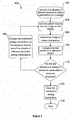
Figure 1 shows schematically an example of a method for setting the mainboard settings for a display panel; -
Figure 2 shows schematically apparatus for setting the mainboard settings for a display panel; -
Figure 3 shows an example of a test pattern comprising different check points; and -
Figure 4 shows an example of a test pattern for checking white scale of a display panel. - In large scale manufacturing of products there are often components of products which are used in a number of different, but related, final products. These components may serve one of a number of purposes. The specific purpose may not only rely on how the component is used within a product, but also on the settings used for the component and for the particular product.
- As a particular example, many display panels require a mainboard. The mainboard is an electronic circuit, similar to a computer's motherboard, which acts inter alia to set the basic specifications of the display panel and to control operation of the display panel generally. The mainboard typically has a number of different components. The settings of at least some of the components are set so as to allow the mainboard to function for multiple different types of display panel. The settings for the mainboard are usually set during a final production stage of the display panel.
- Mainboards such as those used for electronic monitors and other display panels can be used for driving display panels which may be of different types, such as different display panel sizes and different resolutions. The same mainboard must therefore support many different display panel driving options. If a new display panel is to be driven by a particular mainboard, the many different mainboard setting combinations are typically set and then checked manually by a human worker or technician until the settings have been set correctly, i.e. to set the optimum display.
- In setting the mainboard settings for a display panel, often a visual match will be sought between an already optimised display panel and the display panel in need of setting or optimization. The settings for the already optimised display panel may be manually optimised based on the opinion of a specialized technician. Optimization is based on the rendering by the display panel of what is known as a test pattern or test card.
- Test patterns or test cards depict a number of different patterns, shapes, colours, contrasting sections, etc. The settings of the mainboard of the display panel can be judged and adjusted based on the test pattern features. Some of the mainboard settings will remain available for alteration via a menu of the display panel after manufacture, optionally by a purchaser or other end user of the display panel. However, adjustment of some settings will not be available to say a purchaser or other end user of the display panel after the settings have been made by the manufacturer.
- The test pattern as displayed on the non-optimised display panel, i.e. the display panel that is having its mainboard settings set, may be compared with a captured image displayed by an optimised display panel. The captured image of the optimised display panel is taken while the optimised display panel is outputting a test pattern. In some situations, the output of the optimised display panel is viewed directly by a technician when setting a new display panel's mainboard settings.
- There are many different mainboard settings or driving settings used to set the picture on a display panel. It is therefore difficult to try all the combinations of settings one-by-one, particularly when done manually by a person. Also, when the picture is checked by a person, any errors in the fine detail in a picture (e.g. a test pattern or test card) may not be noticed by eye. Thus a combination of settings of the mainboard settings may be incorrectly identified as the optimum settings, which may result in the display panel being driven incorrectly or at least sub-optimally.
- Examples of the present disclosure provide a method for setting mainboard settings by comparing a captured image of the output of an optimised display panel with a captured image of the output of a display panel to be optimised. The comparison may be performed by a comparison module of a controller. Both the optimised and non-optimised display panel render the same test pattern for the compared images.
- Referring to
Figure 1 , in anexample method 100, at 102 a controller connected to the mainboard of a display panel sets one of a plurality of combinations of mainboard settings. As mentioned above, there are many possible combinations of mainboard settings, and each one leads to slightly different driving parameters. Display panel, as referred to throughout the present application, may refer to any electronic display panel. The display panel may be a display panel as comprised within electronic devices such as a television, a monitor for a computer (including a personal computer, tablet computer, etc.), digital signage (either as a whole array or as individual panels of an array), etc. - For example the mainboard settings to be set may comprise colour depth, bitmapping or data-mapping standards for monitors, data rate, LVDS pair swap, etc. Colour depth is expressed as a bit value. This value is the number of bits used per pixel (or per colour channel) when coding a colour image to be displayed on a display panel. For example, there may be an ability to set the colour depth at either 8 bits or 10 bits, or any other number of bits used for providing colour depth. 8 bits of data per shade of green, red, or blue corresponds to approximately 16.7 million distinct colours. If this settings is not set correctly between the display panel and the mainboard, the display panel cannot be driven correctly. If for example the mainboard setting is 8-bit and the display panel setting is 10-bit there will be some missing data on the display panel, resulting in the wrong colour data being output by the display panel. The opposite scenario may also cause problems. For example, if a mainboard with a mainboard colour depth setting of 10-bit sends data to a display panel only capable of displaying 8-bit colour depth, display panel colour data will be saturated for some of the data values.
- Data-mapping standards for monitors include standards such as JEIDA (Japanese Electronic Industry Development Association), VESA (Video Electronics Standards Agency), etc. These standards are developed to assist the interoperability of electronic devices and display panels. Each standard comprises its own data-mapping techniques such that image data received and encoded can be decoded and correlated to pixels. Thus image data is displayed at the correct positions and showing the correct content to provide the desired image. This is because the LVDS data sequence of VESA and JEIDA formats are different. When the display panel hardware is set as having VESA structure and a mainboard is trying to drive the display panel with a setting of JEIDA mode or vice versa, the picture on the display panel will be unclear.
- Data rate in this context relates to the transmission of data in a clocked electronic circuit. Data is transmitted in sync with the cycle of a clock signal of the electronic circuit. When transmitting data in a single clock circuit, or single data rate circuit, data is transmitted using one signal every clock cycle. This is typically on the rising side of the clock cycle. In double clock circuits, often called double data rate circuits, a data signal is transmitted on both the rising and falling side of the clock cycle, and hence twice as often. There is also a configuration called quad data rate. For simplicity the data rate may simply be referred to as single, double, or quad, for the corresponding setting. With regard to display panels, a single clock setting is typically used when driving high definition (HD) display panels, whereas a double clock setting is typically used to drive full high definition (FHD) display panels. Thus, the mainboard setting for data rate is set based on the resolution of the display panel for which the mainboard will be used.
- The LVDS signal format uses differential signalling where each LVDS pair has a positive and a negative line. On the LVDS receiving terminals of the display panel, these positive and negative lines might be reversed compared to the layout of the terminals on the mainboard printed circuit board. Using the swap setting it is possible to swap the positive/negative signals of the LVDS pairs, or even the whole channel on the mainboard, such that the output interface matches the display panel LVDS receiving terminals.
- With a combination of mainboard settings set, the method proceeds to 104, where test pattern data is used to form an image on the display panel for which the mainboard settings are to be set. The test pattern data can be used to form a test card or pattern that contains suitable shapes, colours, patterns, and gradients for observing the driving accuracy and quality of a display panel. Standard test patterns are available for use and are well known in the art.
- At 106 the image displayed on the display panel is captured. The image may be captured by any type of camera capable of accurately reproducing the image that is displayed. The camera should be a digital camera so as to be able to capture a digital image, which can be used in the comparison discussed below. The captured image is passed to the controller. A settings module or scaler block controls the current mainboard setting and is also connected to the camera. The camera is thus triggered to capture an image of the display panel to be used as the test picture when a particular combination of mainboard settings is being used.
- At 108 the controller compares the test picture with a reference picture. The reference picture and the test picture are compared such that it can be seen whether they substantially match. Here, substantially match means the same within a tolerance threshold. For example, it may be that a tolerance threshold is determined such that very minor differences between the captured test picture and the reference picture are deemed negligible. Thus the mainboard of the display panel may be deemed to be optimised by using the current mainboard settings regardless of the minor differences, that is to say, if the test picture and the reference picture are determined to be the same within the tolerance threshold. The tolerance threshold may be set to zero, such that the test picture and the reference picture are considered the same only when identical to each other.
- A test pattern or test card can be formulated such that "check points" are created in different locations within the test card. Each check point corresponds to a different setting of the mainboard. Thus when viewed on a display panel any one check point can provide information about a setting of that particular display panel's mainboard. These same check points thus appear within the captured reference picture, each check point providing reference information about the optimum setting of a different mainboard setting. When a check point of the reference picture is compared with the same respective check point on a test picture it is possible to tell whether the respective setting on the mainboard of the display panel is set correctly or incorrectly. The comparison check points of the captured reference picture and test picture are compared using image processing at a comparison module. The use of test patterns with this check point layout helps to compare pictures where there are minimal differences. This is because each check point correlates to a unique mainboard setting, indicating which mainboard setting should be changed to optimise the test image at that check point, and subsequently optimising the display panel.
- The reference picture and test picture may be compared, as described above, in order to determine whether they are the same or not. The comparison may be performed by comparing one or more of or a combination of colour shade, contrast level, and brightness for the two pictures. The comparison may be made one check point at a time. That is to say, each check point on a test pattern may have its colour shade, contrast, and brightness compared to the colour shade, contrast, and brightness of the same check point in the reference picture. The comparison of each of the three, or a combination of all three, may thus indicate that the corresponding mainboard setting is incorrect. The comparison may also indicate which incorrect setting is currently set, as well as which mainboard setting is the correct mainboard setting. A tolerance threshold may then be set for each criteria of colour shade, contrast, and brightness. An upper and lower threshold may be set for each criteria. The threshold may be set differently for each criteria. For example, brightness may have a high upper threshold and a low bottom threshold as brightness is often very dependent on environment and type of display panel.
- Some example test patterns are shown in
Figure 3 andFigure 4 . InFigure 3 , arrows have been used to indicate a number of examples of different specific check points in the test patterns. The check points may be used to provide points of comparison within the test picture and reference picture, as discussed above.Figure 4 shows by way of example, a test pattern specifically for checking and setting a white scale of a display panel. Arrows are used to indicate the sections with different associated percentage values. The percentage values from left to right are 100%, 95%, 90%, and 85%. Similar test patterns for checking colour exist but are not shown here. - If the test picture and the reference picture are determined not to be the same within the tolerance threshold, then the differences are deemed to be significant. The display panel is then not considered to be optimised by using the current mainboard settings combination. The tolerance threshold may be set in order to negate the presence of certain artefacts found in the captured images which may not be a result of the chosen mainboard setting combination. For example, such artefacts may be reflections from the surface of the display panel being optimised, which may not be present in the image captured of the optimised display panel or vice versa. That is a reflection may be present in the test picture but not in the reference picture.
- If the test picture and the reference picture are determined to be the same within the tolerance threshold, then the current mainboard settings combination is saved. That is to say, the mainboard settings combination that produces the particular test picture captured from the display panel are saved to the mainboard as the driving settings for that display panel. The settings may be saved to the output log of the display panel. There may then be a number of other test patterns displayed on the display panel using the saved mainboard settings in a second round of comparison tests.
- If the test picture and the reference picture are determined not to be the same within the tolerance threshold, the settings module drives the display panel using another, different combination of mainboard settings for the display panel.
- The settings module is invoked by the controller when the controller is connected to a non-optimised mainboard for a display panel which requires settings to be set. The settings module or scaler block may aggregate multiple different signals into one signal for sending to the display panel. The controller triggers a new combination of mainboard settings to be used for the display panel when the test picture and the reference picture are found to be different from each other (i.e. not the same within the tolerance threshold). The settings module outputs LVDS (low-voltage differential signalling) data such that timing information for the different mainboard settings combinations is also transmitted to the display panel's timing controller (not shown). The different mainboard settings combinations to be tested are predefined, but are not necessarily set or used in any particular order. The image of the display panel can then be captured by the camera at times correlating with the different mainboard settings combinations as triggered by the settings module and hence the different display panel outputs.
- As mentioned, subsequent to the determination of a test picture and a reference picture being the same, the particular combination of mainboard settings that produced the test picture in question are saved. The display panel with these mainboard settings may optionally then be subjected to a second round of image comparison tests. At this stage the mainboard settings are kept the same (the saved optimum setting combination from the first round of comparisons), but the test pattern data and the resulting test pattern or test card is changed. That is to say a plurality of different test pattern data are used to drive the display panel and to output a plurality of different images corresponding to the different test patterns. Each different test pattern when displayed is captured to produce a respective test picture. The test picture is compared with the respective reference picture for that test pattern by the controller. This second round of comparison tests may be used to confirm that the mainboard settings saved from the first round of comparison tests is in fact the optimum combination of mainboard settings and may check that other details in the images are being produced correctly. If it is determined that all of the compared test pictures and reference pictures are the same within a tolerance threshold the saved mainboard settings in the display output log of the display panel are maintained.
- Referring to
Figure 2 , there is shown an example of apparatus for setting the mainboard settings for a display panel. Acontroller 202 comprises asettings module 204 and acomparison module 206. Thecontroller 202 is arranged to control acamera 208 and adisplay panel 210. In an example, thecontroller 202 may also be arranged to control an optimiseddisplay panel 212. Thecontroller 202 receives data at an input of the controller from adata source 214. The data comprises test pattern data and may also comprise reference pictures corresponding to the test pattern data. Such received reference pictures may be obtained by the manufacturer or the like that is currently setting the mainboard settings or may be supplied by third party and captured from a remotely located optimised display panel. - The
controller 202 may be one or more processors, or one or more controllers, or some other electronic device that is capable at least of comparing the test picture to a reference picture captured from another display panel with optimum mainboard settings. - The
controller 202 is arranged to control thedisplay panel 210 such that a combination of mainboard settings are defined for use at thedisplay panel 210. Thesettings module 204 of thecontroller 202 determines which combination of mainboard settings fordisplay panel 210 are used at any one time. Thecontroller 202 is also arranged to control thedisplay panel 210 such that the received test pattern data is used to drive thedisplay panel 210 to output an image comprising a corresponding test pattern or test card or the like. Thecontroller 202 is similarly arranged to control thecamera 208 such that an image of thedisplay panel 210 is captured, while a test pattern is being output, to obtain a test picture.Settings module 204 determines when thecamera 208 is required to capture an image ofdisplay panel 210 such that it corresponds to the use of any one particular combination of mainboard settings. The test picture captured by thecamera 208 is received by thecontroller 202 and passed to thecomparison module 206 of thecontroller 202. At thecomparison module 206 the captured test picture and the respective reference picture are compared. When thecomparison module 206 detects that the compared pictures are not the same, thecontroller 202 triggers thesettings module 204 to change the combination of mainboard settings currently used atdisplay panel 210. - The reference pictures used at the
comparison module 206 may be obtained from thedata source 214 or captured as part of the setting of mainboard settings method, as discussed above. In an example, an optimiseddisplay panel 212 may also be controller by thecontroller 202. The optimiseddisplay panel 212 may be controlled such that the received test pattern data is used to cause the optimised display panel to output a corresponding test pattern or test card. The displayed test pattern ondisplay panel 212 can then be captured bycamera 208 to form a reference picture. In this way the reference picture may also be created as part of the mainboard setting method. This may assist in eliminating any interference in the comparison process as a result of artefacts, e.g. due to surface reflections being present in captured images. This is because images of the optimiseddisplay panel 212 and thedisplay panel 210 having been captured at the same physical location are likely to have substantially more similar surface reflections present, and thus fewer differences between the compared pictures. - It will be understood that the processor or processing system or circuitry referred to herein may in practice be provided by a single chip or integrated circuit or plural chips or integrated circuits, optionally provided as a chipset, an application-specific integrated circuit (ASIC), field-programmable gate array (FPGA), digital signal processor (DSP), graphics processing units (GPUs), etc. The chip or chips may comprise circuitry (as well as possibly firmware) for embodying at least one or more of a data processor or processors and a digital signal processor or processors, which are configurable so as to operate in accordance with the exemplary embodiments. In this regard, the exemplary embodiments may be implemented at least in part by computer software stored in (non-transitory) memory and executable by the processor, or by hardware, or by a combination of tangibly stored software and hardware (and tangibly stored firmware).
- The examples described herein are to be understood as illustrative examples of embodiments of the invention. Further embodiments and examples are envisaged. Any feature described in relation to any one example or embodiment may be used alone or in combination with other features. In addition, any feature described in relation to any one example or embodiment may also be used in combination with one or more features of any other of the examples or embodiments, or any combination of any other of the examples or embodiments. Furthermore, equivalents and modifications not described herein may also be employed within the scope of the invention, which is defined in the claims.
Claims (14)
- A method of setting mainboard settings for a mainboard of a display panel, the method comprising:setting one of a plurality of different mainboard setting combinations for the display panel;using test pattern data to form an image on the display panel using said setting combination;capturing said image to create a test picture;comparing the test picture with a reference picture captured from another display panel with optimum mainboard settings, wherein:if said compared test picture and reference picture are the same within a tolerance threshold, saving the mainboard setting combination to the display output log; andif said compared test picture and reference picture are not the same within the tolerance threshold, changing the mainboard setting combination for the display panel to another one of the plurality of different mainboard setting combinations.
- A method according to claim 1, the method comprising:displaying in succession a plurality of different images on the display panel with said saved mainboard settings formed from a plurality of different test pattern data;capturing each of the plurality of different images to create a plurality of respective test pictures;comparing the captured test pictures with respective reference pictures, wherein:if all of said compared test pictures and reference pictures are the same within a tolerance threshold, maintain the saved mainboard settings in the display output log of the display panel; andif at least one of said compared test pictures and reference pictures are not the same within the tolerance threshold, change the saved mainboard setting combination of the display panel to another one of the plurality of different mainboard setting combinations that is different to the setting combination already checked.
- A method according to claim 1 or claim 2, wherein the different mainboard setting combinations comprise different settings including at least one of colour depth, and/or standards for monitors, and/or data rate, and/or LVDS pair swap.
- A method according to claim 3, wherein the colour depth setting is a setting of 8 bit, or 10 bit.
- A method according to claim 3 or claim 4, wherein the standards for monitors setting is a setting of JEIDA, or VESA.
- A method according to any of claims 3 to 5, wherein the data rate setting is a setting of single, double, or quad.
- A method according to any of claims 3 to 6, wherein the LVDS pair swap setting is a setting of yes, or no.
- A method according to any preceding claim, wherein the display panel is a display panel of a television, a computer monitor or digital signage.
- A method according to any preceding claim, wherein the comparing the test picture with a reference picture captured from another display panel with optimum mainboard settings is carried out by a comparison module of a controller.
- A method according to any preceding claim, wherein the method comprises:using test pattern data to form an image on an optimised display panel for which optimum mainboard settings have been set;capturing said image to create the reference picture.
- A method according to claim 10, wherein the optimum mainboard settings of the optimised display panel have been set manually.
- A controller for setting mainboard settings of a display panel, the controller comprising:an input for receiving test pattern data;a settings module configured to set a mainboard settings combination of a mainboard of a display panel and drive the display panel using the test pattern data in accordance with the mainboard settings combination to form an image;an input for receiving image data comprising a test picture of the image displayed by the display panel; anda comparison module configured to compare the test picture with a reference picture of the image;the controller being configured such that:if said compared test picture and reference picture are the same within a tolerance threshold, causing the mainboard setting combination to be saved to a display output log; andif said compared test picture and reference picture are not the same within the tolerance threshold, causing the mainboard setting combination for the display panel to be changed to another of a plurality of different mainboard setting combinations.
- A controller according to claim 12, wherein:the settings module is configured to drive a display panel with said saved mainboard settings to display in succession a plurality of different images formed from a plurality of different test pattern data;the comparison module is configured to compare test pictures of the images displayed by the display panel with respective reference pictures of the images; andthe controller is configured such that:if all of said compared test pictures and reference pictures are the same within a tolerance threshold, the saved mainboard settings in the display output log of the display panel are maintained; andif at least one of said compared test pictures and reference pictures are not the same within the tolerance threshold, the saved mainboard setting combination of the display panel is changed to another, different one of the plurality of different mainboard setting combinations.
- A controller according to claim 12 or claim 13, wherein the settings module is configured to set mainboard settings combinations comprising different settings including at least one of colour depth, and/or standards for monitors, and/or data rate, and/or LVDS pair swap.
Priority Applications (2)
| Application Number | Priority Date | Filing Date | Title |
|---|---|---|---|
| EP17179087.6A EP3422332A1 (en) | 2017-06-30 | 2017-06-30 | Method and controller for setting mainboard settings of a mainboard of a display panel |
| TR2017/11002A TR201711002A2 (en) | 2017-06-30 | 2017-07-27 | Method and controller for setting mainboard settings of a mainboard of a display panel. |
Applications Claiming Priority (1)
| Application Number | Priority Date | Filing Date | Title |
|---|---|---|---|
| EP17179087.6A EP3422332A1 (en) | 2017-06-30 | 2017-06-30 | Method and controller for setting mainboard settings of a mainboard of a display panel |
Publications (1)
| Publication Number | Publication Date |
|---|---|
| EP3422332A1 true EP3422332A1 (en) | 2019-01-02 |
Family
ID=59298237
Family Applications (1)
| Application Number | Title | Priority Date | Filing Date |
|---|---|---|---|
| EP17179087.6A Withdrawn EP3422332A1 (en) | 2017-06-30 | 2017-06-30 | Method and controller for setting mainboard settings of a mainboard of a display panel |
Country Status (2)
| Country | Link |
|---|---|
| EP (1) | EP3422332A1 (en) |
| TR (1) | TR201711002A2 (en) |
Citations (3)
| Publication number | Priority date | Publication date | Assignee | Title |
|---|---|---|---|---|
| US20070043523A1 (en) * | 2005-08-19 | 2007-02-22 | Innolux Display Corp. | System and method for inspecting pictures of a liquid crystal display |
| US20100013846A1 (en) * | 2008-07-15 | 2010-01-21 | Samsung Electronics Co., Ltd. | Display apparatus, and image quality converting method and data creating method using the same |
| WO2017028447A1 (en) * | 2015-08-19 | 2017-02-23 | 京东方科技集团股份有限公司 | Device for adjusting display parameter, method for adjusting display parameter and display device |
-
2017
- 2017-06-30 EP EP17179087.6A patent/EP3422332A1/en not_active Withdrawn
- 2017-07-27 TR TR2017/11002A patent/TR201711002A2/en unknown
Patent Citations (4)
| Publication number | Priority date | Publication date | Assignee | Title |
|---|---|---|---|---|
| US20070043523A1 (en) * | 2005-08-19 | 2007-02-22 | Innolux Display Corp. | System and method for inspecting pictures of a liquid crystal display |
| US20100013846A1 (en) * | 2008-07-15 | 2010-01-21 | Samsung Electronics Co., Ltd. | Display apparatus, and image quality converting method and data creating method using the same |
| WO2017028447A1 (en) * | 2015-08-19 | 2017-02-23 | 京东方科技集团股份有限公司 | Device for adjusting display parameter, method for adjusting display parameter and display device |
| US20170221403A1 (en) * | 2015-08-19 | 2017-08-03 | Boe Technology Group Co., Ltd. | Apparatus and method for adjusting display parameters and display apparatus |
Also Published As
| Publication number | Publication date |
|---|---|
| TR201711002A2 (en) | 2019-01-21 |
Similar Documents
| Publication | Publication Date | Title |
|---|---|---|
| CN108682367B (en) | Display self-monitoring method and display | |
| EP3242268A1 (en) | Method for automatically identifying and calibrating medical color and gray-scale images | |
| US12266287B2 (en) | Gamma debugging method, apparatus and device | |
| KR100859938B1 (en) | Method and device of rapidly generating a gray-level versus brightness curve of a display | |
| US10546368B2 (en) | Method and device for compensating the perceptual bias of edge boost in a display panel | |
| CN114283731B (en) | Pressure drop compensation method, apparatus, device, medium and program product | |
| CN107018438B (en) | Display control apparatus, display control method and computer-readable medium | |
| EP3276602A1 (en) | A method and system for calibrating a display screen | |
| KR20220021712A (en) | Electronic apparatus, display apparatus and the controlling method thereof | |
| CN106205463B (en) | Control system for non-rectangular display screen | |
| CN103941112B (en) | System and method for detecting multiple image signals | |
| CN106685700B (en) | A DMD data fault detection method, device and system | |
| KR100771763B1 (en) | Automatic image correcting circuit | |
| KR101552826B1 (en) | Test system for fail of display pane | |
| CN114898696B (en) | Gamma voltage adjustment method, device, equipment and storage medium | |
| US20150178036A1 (en) | Video output device, information processor, and method | |
| US20180096640A1 (en) | Information outputting method, electronic equipment, and displaying apparatus | |
| CN115171581A (en) | Display panel, peep-proof display method, device, storage medium and display device | |
| US20070043523A1 (en) | System and method for inspecting pictures of a liquid crystal display | |
| TW201729581A (en) | System and method for non-panel TCON module test | |
| US20240119574A1 (en) | Method of adjusting displayed image and display system | |
| CN106601187A (en) | Display control device, control card, display device and control method thereof | |
| JP2021118500A (en) | Display device, display system and abnormality detection method | |
| CN103957381A (en) | Data transmission device, method and system | |
| TW201303316A (en) | Testing structure, method and system utilizing the same |
Legal Events
| Date | Code | Title | Description |
|---|---|---|---|
| PUAI | Public reference made under article 153(3) epc to a published international application that has entered the european phase |
Free format text: ORIGINAL CODE: 0009012 |
|
| STAA | Information on the status of an ep patent application or granted ep patent |
Free format text: STATUS: THE APPLICATION HAS BEEN PUBLISHED |
|
| AK | Designated contracting states |
Kind code of ref document: A1 Designated state(s): AL AT BE BG CH CY CZ DE DK EE ES FI FR GB GR HR HU IE IS IT LI LT LU LV MC MK MT NL NO PL PT RO RS SE SI SK SM TR |
|
| AX | Request for extension of the european patent |
Extension state: BA ME |
|
| STAA | Information on the status of an ep patent application or granted ep patent |
Free format text: STATUS: REQUEST FOR EXAMINATION WAS MADE |
|
| 17P | Request for examination filed |
Effective date: 20190701 |
|
| RBV | Designated contracting states (corrected) |
Designated state(s): AL AT BE BG CH CY CZ DE DK EE ES FI FR GB GR HR HU IE IS IT LI LT LU LV MC MK MT NL NO PL PT RO RS SE SI SK SM TR |
|
| STAA | Information on the status of an ep patent application or granted ep patent |
Free format text: STATUS: EXAMINATION IS IN PROGRESS |
|
| 17Q | First examination report despatched |
Effective date: 20210609 |
|
| STAA | Information on the status of an ep patent application or granted ep patent |
Free format text: STATUS: THE APPLICATION HAS BEEN WITHDRAWN |
|
| 18W | Application withdrawn |
Effective date: 20211213 |