EP3422329A1 - Display device and method for operating a display device - Google Patents
Display device and method for operating a display device Download PDFInfo
- Publication number
- EP3422329A1 EP3422329A1 EP17178348.3A EP17178348A EP3422329A1 EP 3422329 A1 EP3422329 A1 EP 3422329A1 EP 17178348 A EP17178348 A EP 17178348A EP 3422329 A1 EP3422329 A1 EP 3422329A1
- Authority
- EP
- European Patent Office
- Prior art keywords
- lighting elements
- movable
- fixed
- display device
- carrier structure
- Prior art date
- Legal status (The legal status is an assumption and is not a legal conclusion. Google has not performed a legal analysis and makes no representation as to the accuracy of the status listed.)
- Granted
Links
Images


Classifications
-
- G—PHYSICS
- G09—EDUCATION; CRYPTOGRAPHY; DISPLAY; ADVERTISING; SEALS
- G09F—DISPLAYING; ADVERTISING; SIGNS; LABELS OR NAME-PLATES; SEALS
- G09F19/00—Advertising or display means not otherwise provided for
- G09F19/02—Advertising or display means not otherwise provided for incorporating moving display members
-
- G—PHYSICS
- G09—EDUCATION; CRYPTOGRAPHY; DISPLAY; ADVERTISING; SEALS
- G09F—DISPLAYING; ADVERTISING; SIGNS; LABELS OR NAME-PLATES; SEALS
- G09F27/00—Combined visual and audible advertising or displaying, e.g. for public address
- G09F27/005—Signs associated with a sensor
-
- G—PHYSICS
- G09—EDUCATION; CRYPTOGRAPHY; DISPLAY; ADVERTISING; SEALS
- G09F—DISPLAYING; ADVERTISING; SIGNS; LABELS OR NAME-PLATES; SEALS
- G09F9/00—Indicating arrangements for variable information in which the information is built-up on a support by selection or combination of individual elements
- G09F9/30—Indicating arrangements for variable information in which the information is built-up on a support by selection or combination of individual elements in which the desired character or characters are formed by combining individual elements
- G09F9/33—Indicating arrangements for variable information in which the information is built-up on a support by selection or combination of individual elements in which the desired character or characters are formed by combining individual elements being semiconductor devices, e.g. diodes
-
- G—PHYSICS
- G09—EDUCATION; CRYPTOGRAPHY; DISPLAY; ADVERTISING; SEALS
- G09F—DISPLAYING; ADVERTISING; SIGNS; LABELS OR NAME-PLATES; SEALS
- G09F9/00—Indicating arrangements for variable information in which the information is built-up on a support by selection or combination of individual elements
- G09F9/30—Indicating arrangements for variable information in which the information is built-up on a support by selection or combination of individual elements in which the desired character or characters are formed by combining individual elements
- G09F9/37—Indicating arrangements for variable information in which the information is built-up on a support by selection or combination of individual elements in which the desired character or characters are formed by combining individual elements being movable elements
Definitions
- the invention relates to a display device. Further, the invention relates to a respective method for operating a display device.
- LED wall systems are integrated information display solutions, which size is customizable for different applications. LED wall products are generally used in the advertisement, information, or entertainment sectors. LED wall systems usually consist of red, green and blue light sources, especially LEDs. The red, green and blue light sources may be individually controlled. In addition, triples of one red, one green and one blue light source may be arranged near each other to form virtual RGB pixels.
- LED wall systems are provided for indoor or outdoor use. Outdoor LED wall systems are designed to work efficiently at daylight and to be resistant to variable weather conditions, like rain, wind and the like.
- mesh LED wall systems may be used, which comprise openings or open areas or spaces on its surface. With these openings the surface of the LED wall systems is reduced and air or wind may pass through the openings. Therefore, with the openings the air pressure on the surface of the LED wall systems is reduced. The LED wall systems are therefore more resistant to windy weather.
- these openings require space and therefore the distance between the LEDs or pixels, also called pitch distance, is increased.
- the number of LEDs per surface area or the resolution is reduced, since less LEDs may be placed in the same surface area. Therefore, while being more durable or resistant regarding wind mesh LED wall systems have the disadvantage of providing a lower resolution.
- the present invention provides a display device with the features of claim 1 and a method for operating a display device with the features of claim 9.
- the present invention is based on the finding that mesh LED wall systems are usually installed in windy areas as a preventive measure. This means that a LED wall systems with reduced resolution is installed, even if the condition of strong winds may only be present on rare occasions.
- the present invention takes into account this finding and provides a display device that may work as a highresolution display device without openings and provides a maximized number of lighting elements per surface area. This would be the display device with the movable second lighting elements in the first position. In this position, the movable second lighting elements are arranged in the openings between the fixed first lighting elements.
- the movable second lighting elements may be moved into a second position. In the second position the movable second lighting elements are removed from the openings between the fixed first lighting elements and leave the openings free for air to flow through the openings.
- the display device may represent a standard high resolution display device, as they are usually used indoors.
- the display device may represent a mesh LED wall system that comprises openings for wind to flow through the openings, as they are usually used in outdoor applications.
- the present invention consequently provides a LED wall system with a dual solid or mesh structure that may be controllably selected.
- the control unit may e.g. receive the control signal from a user or automatically from an automation system that provides the control signal based on the current weather conditions in the area of the display device. The control unit may then control actuators of the movable second lighting elements to position the movable second lighting elements accordingly. It is understood, that the control unit may store the current position of the movable second lighting elements and only change their position if required.
- the control unit may e.g. be a dedicated control unit for controlling the movable second lighting elements to move into the first or the second position.
- the control unit may also be integrated into another control device of the display device.
- the actuators may e.g. comprise electric motors or linear drives.
- the actuators may e.g. comprise flaps and e.g. air guides or tunnels that focus the wind onto the flaps.
- the flaps may be spring loaded. Therefore the deflection of the flaps will depend on the force of the springs and the strength of the wind.
- the deflection of the flaps may then directly be used to move the movable second lighting elements from the first position to the second position.
- an arrangement of levers and beams may be provided that translates the rotary deflection of the flaps into a linear movement of the movable second lighting elements.
- the display device may comprise a first fixed carrier structure, wherein the fixed first lighting elements may be arranged on the first fixed carrier structure.
- the display device may comprise a second movable carrier structure, wherein the movable second lighting elements may be arranged on the second movable carrier structure.
- the first fixed carrier structure may e.g. comprise a frame that carries the fixed first lighting elements.
- the second movable carrier structure may also comprise a frame that carries the movable second lighting elements.
- the second movable carrier structure may e.g. be movable, e.g. slidable, with respect to the first fixed carrier structure.
- the second movable carrier structure may e.g. be slidably arranged, e.g. like slidable shutters that may be mounted on windows.
- the movable second lighting elements may be moved all together, without the need to individually move every single movable second lighting element.
- the first fixed carrier structure may comprise a first outer frame and a plurality of parallel first beams arranged in the frame that are configured to carry the fixed first lighting elements and are spaced apart from each other by the predefined spacing.
- the second movable carrier structure may comprise a second outer frame and a plurality of parallel second beams arranged in the frame that are configured to carry the movable second lighting elements and are spaced apart from each other by the predefined spacing.
- the second movable carrier structure may be arranged behind the first fixed carrier structure.
- the first fixed carrier structure and the second movable carrier structure may essentially comprise the same mechanical arrangement. Both the first fixed carrier structure and the second movable carrier structure each form a kind of plane and the fixed first lighting elements or the movable second lighting elements, respectively, may be are arranged in said planes.
- the first beams of the first fixed carrier structure being spaced apart from each other by the predefined spacing refers to the beams with the fixed first lighting elements attached comprising the openings with the predefined spacing between them.
- the second beams of the second movable carrier structure being spaced apart from each other by the predefined spacing refers to the second beams with the movable second lighting elements attached also comprising openings with the predefined spacing between them.
- the second beams with the movable second lighting elements attached may be as broad as defined by the predefined spacing.
- the first beams and the second beams may be positioned horizontally next to each other in the first position of the second movable carrier structure. In the second position of the second movable carrier structure the second beams will move behind the first beams and leave free the openings between the first beams.
- the second movable carrier structure may also move in front of the first fixed carrier structure.
- the fixed first lighting elements may comprise a transparent section
- the movable second lighting elements may each be arranged behind the transparent section in the second position.
- the second lighting elements may comprise the transparent sections.
- the movable second lighting elements may simply be moved away from the openings.
- the transparent sections of the fixed first lighting elements may allow the movable second lighting elements to be used also in the second position. In this position, instead of increasing the resolution of the display device, the movable second lighting elements may increase the brightness of the display device.
- the movable second lighting elements may further comprise covers, especially black covers that in the first position cover the transparent sections. Without the covers sunlight or other light may shine through the transparent sections. The transparent sections may therefore appear illuminated although the respective pixel may be black or turned-off.
- the first fixed carrier structure may comprise a first outer frame and a plurality of parallel first beams arranged in the frame that are configured to carry the fixed first lighting elements and are spaced apart from each other by the predefined spacing.
- the second movable carrier structure may comprise second beams that are configured to carry the movable second lighting elements, each beam comprising a hinge.
- the second beams may each be installed via the respective hinges adjacent to one of the first beams.
- the second beams may e.g. be hingedly attached to the first beams or to any carrier behind the first beams via the hinges.
- the second beams may therefore be clapped or flapped out of the openings between the fixed first lighting elements to open up the openings and allow air to flow through the openings.
- control signal may indicate to the control unit how many of the second beams to clap or flap out of the respective openings.
- first fixed carrier structure and/or the first beams and/or the second movable carrier structure and/or the second beams may also comprise electrical connections for supplying the fixed first lighting elements and/or the movable second lighting elements with electrical power and/or control signals.
- the display device may comprise a sensor configured to measure a wind speed and/or a pressure on the display device caused by wind.
- the control unit may be configured to receive sensor data from the sensor as the control signal.
- control signal may e.g. be provided by users or by an automation system. However, that would always require an external authority to control the change of state of the display device.
- the senor is provided.
- the sensor may e.g. determine a speed of wind in the area of installation of the display device.
- the sensor may also determine the pressure that wind puts on the display device.
- the control unit may then use the sensor signal or data as control signal.
- the control unit may e.g. compare the speed of wind or pressure with a predetermined threshold value to determine if the display device should be operated with the movable second lighting elements in the first or second position.
- the display device may comprise an image processor configured to adapt at least the resolution of incoming image data according to the current position of the movable second lighting elements.
- the display device will provide a higher resolution than with the movable second lighting elements in the second position.
- image data refers to any data that may be displayed either as image or video on the display device.
- the image data may e.g. be provided in the high resolution, i.e. the resolution of the display device with the movable second lighting elements in the first position. If the movable second lighting elements are in the first position, the image processor may therefore directly display the image data via the fixed first lighting elements and the movable second lighting elements. If the movable second lighting elements are then put into the second position, the image processor may correct the resolution of the image data prior to displaying the image data on the fixed first lighting elements only.
- the horizontal resolution will be reduced to half the original resolution.
- the fixed first lighting elements and/or the movable second lighting elements may each comprise a single one colored light source or a combination of at least two light sources of different colors.
- lighting element may refer to elements with single color or one-colored light sources. Such light sources may e.g. comprise LEDs or the like. The term may also refer to lighting elements with combinations of light sources of e.g. three colors, like red, green and blue. Such combinations may also be called pixels or virtual pixels. The lighting elements may further include any mechanical carrier necessary and comprise respective electrical signal lines to drive the light sources. It is understood, that lighting elements with combinations of light sources may e.g. be provided as single RGB-LED.
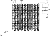
- Fig. 1 shows a block diagram of an embodiment of a display device 100.
- the display device 100 comprises a plurality of fixed first lighting elements 101.
- the fixed first lighting elements 101 are arranged in columns.
- the columns comprise a predefined distance to each other thereby forming openings 102 between the laterally adjacent fixed first lighting elements 101.
- the display device 100 comprises controllably movable second lighting elements 103.
- the movable second lighting elements 103 are also arranged in columns and may be moved from a first position to a second position forth and back.
- the movable second lighting elements 103 are shown in the first position. In the first position the movable second lighting elements 103 are positioned in the openings 102.
- Only one of the fixed first lighting elements 101 and the movable second lighting elements 103 are provided with reference signs. This also applies to Figs. 2 - 6 .
- the display device 100 further comprises a control unit 104 that is coupled at least to the movable second lighting elements 103 to control the movable second lighting elements 103 to move into the first or the second position based on a control signal 105.
- the control unit 104 may e.g. be a dedicated control unit 104 that is provided exclusively to control the movable second lighting elements 103.
- the control unit 104 may e.g. comprise power drivers (not shown) that provide the required electrical energy to drive e.g. electric actuators that move the movable second lighting elements 103.
- the control unit 104 may be arranged e.g. as a function of a central control unit of the display device 100, e.g. as a software component.
- the control signal 105 may e.g. be provided by an external control unit or manually by an operator of the display device 100.
- the display device 100 may further comprise an optional sensor 106.
- the sensor 106 may e.g. detect the wind or the pressure that wind puts on the display device 100 and generate an according control signal 105.
- the fixed first lighting elements 101 and the movable second lighting elements 103 may e.g. comprise LED based lighting elements, e.g. RGB-LED based lighting elements.
- the display device 100 may e.g. be an outdoor LED wall. Such a LED wall may e.g. be used to display commercials or any other image or video.
- the movable second lighting elements 103 cover the openings 102.
- the display device 100 comprises a closed surface. Wind may therefore provide an increased pressure on the display device 100.
- the display device 100 may display image data with a high resolution.
- the movable second lighting elements 103 do not cover the openings 102 and allow wind to pass through the openings 102.
- the movable second lighting elements 103 may e.g. be moved or shifted laterally and remain seated behind the fixed first lighting elements 101.
- the display device 100 may display image data only with half the horizontal resolution.
- the control unit 104 or any other processing unit of the display device 100 may e.g. comprise an image processor (not separately shown) that may modify the resolution of image data that should be displayed on the display device 100 according to the position of the movable second lighting elements 103.
- the image processor may e.g. divide the horizontal resolution of the image data by 2 when the movable second lighting elements 103 are in the second position.
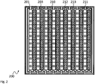
- Fig. 2 shows a block diagram of another display device 200.
- the display device 200 may comprise the same elements as described above for the display device 100.
- the display device 200 therefore also comprises fixed first lighting elements 201 and movable second lighting elements 203.
- the display device 200 further comprises a first outer frame 210.
- the first outer frame 210 further carries a plurality of first beams 211.
- the first beams 211 are vertically oriented and arranged in parallel.
- the display device 200 comprises a second outer frame 212 with a plurality of second beams 213.
- the second beams 213 are also vertically oriented and arranged in parallel.
- the outer frame 212 and therefore the second beams 213 are positioned such that the movable second lighting elements 203 are settled in the openings between the fixed first lighting elements 201. In this position, the full vertical resolution of the display device 200 may be provided.
- the outer frame 212 and therefore the second beams 213 are positioned such that the movable second lighting elements 203 are positioned behind the fixed first lighting elements 201 and leave the openings between the fixed first lighting elements 201 free for air to flow through. Therefore, the pressure on the display device 200 may be reduced.
- the outer frame 212 may be guided by rails and may be driven e.g. by an electric motor or the like.
- Fig. 3 shows a block diagram of an embodiment of another display device 300 in a top view.
- the display device 300 comprises the fixed first lighting elements 301 in the front and the movable second lighting elements 303 behind the fixed first lighting elements 301.
- the fixed first lighting elements 301 are mounted on a first fixed carrier structure 315.
- the movable second lighting elements 303 are mounted on a second movable carrier structure 316.
- the fixed first lighting elements 301 and the movable second lighting elements 303 are mounted in columns with a predefined spacing between the columns. That is the same for the fixed first lighting elements 301 and the movable second lighting elements 303.
- It is further hinted at by a double headed arrow that the second movable carrier structure 316 may be laterally moved behind the first fixed carrier structure 315.
- Fig. 3 the display device 300 is shown with the second movable carrier structure 316 in the first position.
- the movable second lighting elements 303 are positioned behind the openings 302. From the front, the movable second lighting elements 303 will therefore be visible and will form a display plane with the fixed first lighting elements 301.
- the full horizontal resolution of the display device 300 may be provided. In exchange wind or air will put a higher pressure on the display device 300.
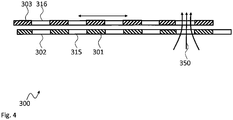
- Fig. 4 shows another block diagram of the display device 300 in a top view.
- the second movable carrier structure 316 is in the second position. It can be seen that in this position the free spaces between the movable second lighting elements 303 in the second movable carrier structure 316 overlap with the openings 302 in the first fixed carrier structure 315.
- Wind 350 may therefore blow directly through the openings 302.
- the wind will only put pressure on the fixed first lighting elements 301, thereby reducing the pressure or load on the display device 300.
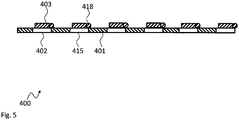
- Fig. 5 shows a block diagram of another display device 400 in a top view.
- the display device 400 comprises the fixed first lighting elements 401 in the front and the movable second lighting elements 403 behind the fixed first lighting elements 401.
- the fixed first lighting elements 401 are mounted on a first fixed carrier structure 415.
- the movable second lighting elements 403 are not mounted on a second movable carrier structure. Instead the movable second lighting elements 403 or the vertical beams carrying the movable second lighting elements 403 are coupled by hinges 418 to the first fixed carrier structure 415.
- movable second lighting elements 403 are shown in the first position. In this position the movable second lighting elements 403 lay behind or cover the openings 402. From the front, the movable second lighting elements 403 can be seen in this position.
- the hinges 418 allow swinging the movable second lighting elements 403 back to open up the openings 402.
- the hinges 418 may e.g. be coupled to a not-shown mechanical arrangement that allows swinging open the movable second lighting elements 403.
- Such an arrangement may e.g. comprise rods, beams and the like that may be actuated e.g. by an electric motor or the above already mentioned flaps arrangement.
- Fig. 6 shows a block diagram of the display device 400 in a top view with the movable second lighting elements 403 in a possible second position.
- the movable second lighting elements 403 are rotated clockwise by the hinges 418 about 90°. It is understood that the movable second lighting elements 403 may also be rotated clockwise about 180°.
- the opening angle of the movable second lighting elements 403 may also be possible to adjust the opening angle of the movable second lighting elements 403 to an angle between 0° and 90° or 180°. Such an arrangement would allow to adjust the size if the openings 402 and e.g. open up the openings 402 only a little. In this position the pressure on the display device 400 could be reduced but the movable second lighting elements 403 could still be viewed from the front, i.e. without reducing the horizontal resolution of the display device 400.
- the movable second lighting elements 403 are shown behind the fixed first lighting elements 401, in possible embodiments, the movable second lighting elements 403 may also be positioned in front of the fixed first lighting elements 401.
- the hinges 418 may be spring loaded hinges 418.
- the springs of the spring loaded hinges 418 may be adapted according to a maximum wind force or pressure. This means that if the pressure on the movable second lighting elements 403 exceeds that maximum pressure, the movable second lighting elements 403 will mechanically swing back and open up the openings 402. With the spring loaded hinges 418 the angle of opening or the angle of the swing back may depend on the wind. Further, the movable second lighting elements 403 will automatically swing back into the first position if the wind or the pressure on the movable second lighting elements 403 is reduced.
- the movement of the movable second lighting elements has been shown as horizontal movement above, the movable second lighting elements may also be arranged to move vertically.
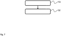
- Fig. 7 shows a flow diagram of a method for operating a display device 100, 200, 300, 400.
- the method comprises receiving S1 a position control signal 105. Further, the method comprises moving S2 a plurality of controllably movable second lighting elements 103, 203, 303, 403 of the display device 100, 200, 300, 400 relative to a plurality of fixed first lighting elements 101, 201, 301, 401 of the display device 100, 200, 300, 400 based on the position control signal 105 in a first position or a second position.
- the plurality of fixed first lighting elements 101, 201, 301, 401 are arranged with a predefined spacing to each other forming openings 102, 302, 402 between the fixed first lighting elements 101, 201, 301, 401, and wherein the movable second lighting elements 103, 203, 303, 403 are movable from the first position to the second position, and wherein in the first position the second lighting elements 103, 203, 303, 403 are arranged interlaced in the openings 102, 302, 402 with the fixed first lighting elements 101, 201, 301, 401 and in the second position the second lighting elements 103, 203, 303, 403 are arranged to leave the openings 102, 302, 402 between the fixed first lighting elements 101, 201, 301, 401 uncovered.
- Moving S2 may comprise moving a second movable carrier structure 316 relative to a first fixed carrier structure 315, 415.
- the movable second lighting elements 103, 203, 303, 403 may be arranged on the second movable carrier structure 316 and the fixed first lighting elements 101, 201, 301, 401 may be arranged on the first fixed carrier structure 315, 415.
- the first fixed carrier structure 315, 415 may further comprise a first outer frame 210 and a plurality of parallel first beams 211 arranged in the frame that carry the fixed first lighting elements 101, 201, 301, 401 and are spaced apart from each other by the predefined spacing.
- the second movable carrier structure 316 may comprise a second outer frame 212 and a plurality of parallel second beams 213 arranged in the frame that carry the movable second lighting elements 103, 203, 303, 403 and are spaced apart from each other by the predefined spacing.
- moving S2 may comprise moving the second movable carrier structure 316 parallel to the first fixed carrier structure 315, 415 behind or in front of the first fixed carrier structure 315, 415, especially in the display plane of the display device 100, 200, 300, 400 or parallel to the display plane.
- Moving S2 into the second position may also comprise moving the movable second lighting elements 103, 203, 303, 403 in the second position behind a transparent section of the fixed first lighting elements 101, 201, 301, 401.
- a transparent section of the movable second lighting elements 103, 203, 303, 403 may be moved in front of the fixed first lighting elements 101, 201, 301, 401.
- the first fixed carrier structure 315, 415 may comprise a first outer frame 210 and a plurality of parallel first beams 211 arranged in the frame that carries the fixed first lighting elements 101, 201, 301, 401 and are spaced apart from each other by the predefined spacing.
- the second movable carrier structure 316 may comprise second beams 213 that carry the movable second lighting elements 103, 203, 303, 403, each beam comprising a hinge 418.
- the second beams 213 may each be installed via the respective hinges 418 adjacent to one of the first beams 211.
- moving S2 into the first position may comprise folding the second beams 213 via the hinges 418 to cover the openings 102, 302, 402 between the fixed first lighting elements 101, 201, 301, 401.
- Moving S2 into the second position may comprise folding the second beams 213 via the hinges 418 to uncover the openings 102, 302, 402 between the fixed first lighting elements 101, 201, 301, 401.
- the method may also comprise adapting at least the resolution of image data incoming in the display device 100, 200, 300, 400 according to the current position of the movable second lighting elements 103, 203, 303, 403.
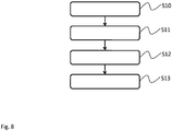
- Fig. 8 shows a block diagram of another method for operating a display device 100, 200, 300, 400.
- the method comprises measuring S10 a wind speed and/or a pressure on the display device 100, 200, 300, 400 caused by wind.
- the above mentioned position control signal 105 may be generated based on the measured wind speed and/or pressure.
- step S11 the current position of the movable second lighting elements 103, 203, 303, 403 is determined and in step S12 it is decided if a change of position for the movable second lighting elements 103, 203, 303, 403 is necessary. If needed, in step S13 the structure of the display device 100, 200, 300, 400 is changed as required, i.e. the movable second lighting elements 103, 203, 303, 403 positioned as required.
- the present invention provides a display device 100, 200, 300, 400 comprising a plurality of fixed first lighting elements 101, 201, 301, 401 arranged with a predefined spacing to each other forming openings 102, 302, 402 between the fixed first lighting elements 101, 201, 301, 401, a plurality of controllably movable second lighting elements 103, 203, 303, 403, wherein the movable second lighting elements 103, 203, 303, 403 are movable from a first position to a second position, and wherein in the first position the second lighting elements 103, 203, 303, 403 are arranged interlaced in the openings 102, 302, 402 with the fixed first lighting elements 101, 201, 301, 401 and in the second position the second lighting elements 103, 203, 303, 403 are arranged to leave the openings 102, 302, 402 between the fixed first lighting elements 101, 201, 301, 401 uncovered, and a control unit 104 configured to control
Landscapes
- Physics & Mathematics (AREA)
- General Physics & Mathematics (AREA)
- Engineering & Computer Science (AREA)
- Theoretical Computer Science (AREA)
- Business, Economics & Management (AREA)
- Accounting & Taxation (AREA)
- Marketing (AREA)
- Devices For Indicating Variable Information By Combining Individual Elements (AREA)
- Fastening Of Light Sources Or Lamp Holders (AREA)
Abstract
Description
- The invention relates to a display device. Further, the invention relates to a respective method for operating a display device.
- Although applicable to any display device, the present invention will mainly be described in conjunction with outdoor LED wall systems.
- LED wall systems are integrated information display solutions, which size is customizable for different applications. LED wall products are generally used in the advertisement, information, or entertainment sectors. LED wall systems usually consist of red, green and blue light sources, especially LEDs. The red, green and blue light sources may be individually controlled. In addition, triples of one red, one green and one blue light source may be arranged near each other to form virtual RGB pixels.
- LED wall systems are provided for indoor or outdoor use. Outdoor LED wall systems are designed to work efficiently at daylight and to be resistant to variable weather conditions, like rain, wind and the like.
- In areas with especially windy weather conditions, so called mesh LED wall systems may be used, which comprise openings or open areas or spaces on its surface. With these openings the surface of the LED wall systems is reduced and air or wind may pass through the openings. Therefore, with the openings the air pressure on the surface of the LED wall systems is reduced. The LED wall systems are therefore more resistant to windy weather. However, these openings require space and therefore the distance between the LEDs or pixels, also called pitch distance, is increased. In addition, the number of LEDs per surface area or the resolution is reduced, since less LEDs may be placed in the same surface area. Therefore, while being more durable or resistant regarding wind mesh LED wall systems have the disadvantage of providing a lower resolution.
- Accordingly, there is a need for improved LED wall systems with high wind resistance and an increased resolution.
- The present invention provides a display device with the features of claim 1 and a method for operating a display device with the features of claim 9.
- Accordingly, it is provided:
- A display device comprising a plurality of fixed first lighting elements arranged with a predefined spacing, e.g. in vertical and/or horizontal direction, to each other forming openings between the fixed first lighting elements, and a plurality of controllably movable second lighting elements, wherein the movable second lighting elements are movable from a first position to a second position, and wherein in the first position the second lighting elements are arranged interlaced in the openings with the fixed first lighting elements and in the second position the second lighting elements are arranged to leave the openings between the fixed first lighting elements uncovered, and a control unit configured to control the controllably movable second lighting elements to move into the first position or the second position based on a control signal.
- Further, it is provided:
- A method for operating a display device, the method comprising receiving a position control signal, and moving a plurality of controllably movable second lighting elements of the display device relative to a plurality of fixed first lighting elements of the display device based on the position control signal in a first position or a second position, wherein the plurality of fixed first lighting elements are arranged with a predefined spacing to each other forming openings between the fixed first lighting elements, and wherein the movable second lighting elements are movable from the first position to the second position and back, and wherein in the first position the second lighting elements are arranged interlaced in the openings with the fixed first lighting elements and in the second position the second lighting elements are arranged to leave the openings between the fixed first lighting elements uncovered.
- The present invention is based on the finding that mesh LED wall systems are usually installed in windy areas as a preventive measure. This means that a LED wall systems with reduced resolution is installed, even if the condition of strong winds may only be present on rare occasions.
- The present invention takes into account this finding and provides a display device that may work as a highresolution display device without openings and provides a maximized number of lighting elements per surface area. This would be the display device with the movable second lighting elements in the first position. In this position, the movable second lighting elements are arranged in the openings between the fixed first lighting elements.
- In addition, the movable second lighting elements may be moved into a second position. In the second position the movable second lighting elements are removed from the openings between the fixed first lighting elements and leave the openings free for air to flow through the openings.
- Therefore, with the movable second lighting elements in the first position, the display device may represent a standard high resolution display device, as they are usually used indoors. In contrast, with the movable second lighting elements in the second position, the display device may represent a mesh LED wall system that comprises openings for wind to flow through the openings, as they are usually used in outdoor applications. The present invention consequently provides a LED wall system with a dual solid or mesh structure that may be controllably selected.
- The control unit may e.g. receive the control signal from a user or automatically from an automation system that provides the control signal based on the current weather conditions in the area of the display device. The control unit may then control actuators of the movable second lighting elements to position the movable second lighting elements accordingly. It is understood, that the control unit may store the current position of the movable second lighting elements and only change their position if required.
- The control unit may e.g. be a dedicated control unit for controlling the movable second lighting elements to move into the first or the second position. Alternatively, the control unit may also be integrated into another control device of the display device. The actuators may e.g. comprise electric motors or linear drives.
- As an alternative, the actuators may e.g. comprise flaps and e.g. air guides or tunnels that focus the wind onto the flaps. The flaps may be spring loaded. Therefore the deflection of the flaps will depend on the force of the springs and the strength of the wind. The deflection of the flaps may then directly be used to move the movable second lighting elements from the first position to the second position. For example an arrangement of levers and beams may be provided that translates the rotary deflection of the flaps into a linear movement of the movable second lighting elements.
- Further embodiments of the present invention are subject of the further subclaims and of the following description, referring to the drawings.
- In an embodiment, the display device may comprise a first fixed carrier structure, wherein the fixed first lighting elements may be arranged on the first fixed carrier structure. In addition, the display device may comprise a second movable carrier structure, wherein the movable second lighting elements may be arranged on the second movable carrier structure.
- The first fixed carrier structure may e.g. comprise a frame that carries the fixed first lighting elements. The second movable carrier structure may also comprise a frame that carries the movable second lighting elements. The second movable carrier structure may e.g. be movable, e.g. slidable, with respect to the first fixed carrier structure. The second movable carrier structure may e.g. be slidably arranged, e.g. like slidable shutters that may be mounted on windows.
- By providing the first fixed carrier structure and the second movable carrier structure, the movable second lighting elements may be moved all together, without the need to individually move every single movable second lighting element.
- In another embodiment, the first fixed carrier structure may comprise a first outer frame and a plurality of parallel first beams arranged in the frame that are configured to carry the fixed first lighting elements and are spaced apart from each other by the predefined spacing. Further, the second movable carrier structure may comprise a second outer frame and a plurality of parallel second beams arranged in the frame that are configured to carry the movable second lighting elements and are spaced apart from each other by the predefined spacing. In addition, the second movable carrier structure may be arranged behind the first fixed carrier structure.
- The first fixed carrier structure and the second movable carrier structure may essentially comprise the same mechanical arrangement. Both the first fixed carrier structure and the second movable carrier structure each form a kind of plane and the fixed first lighting elements or the movable second lighting elements, respectively, may be are arranged in said planes.
- The first beams of the first fixed carrier structure being spaced apart from each other by the predefined spacing refers to the beams with the fixed first lighting elements attached comprising the openings with the predefined spacing between them.
- Analogously, the second beams of the second movable carrier structure being spaced apart from each other by the predefined spacing refers to the second beams with the movable second lighting elements attached also comprising openings with the predefined spacing between them. In addition, the second beams with the movable second lighting elements attached may be as broad as defined by the predefined spacing.
- If the second movable carrier structure is movably, especially slidably, arranged behind the first fixed carrier structure, the first beams and the second beams may be positioned horizontally next to each other in the first position of the second movable carrier structure. In the second position of the second movable carrier structure the second beams will move behind the first beams and leave free the openings between the first beams.
- It is understood, that the second movable carrier structure may also move in front of the first fixed carrier structure.
- In an embodiment, the fixed first lighting elements may comprise a transparent section, and the movable second lighting elements may each be arranged behind the transparent section in the second position.
- If the second movable carrier structure moves in front of the first fixed carrier structure, the second lighting elements may comprise the transparent sections.
- In the second position the movable second lighting elements may simply be moved away from the openings. However, since the movable second lighting elements are still capable of providing light, the transparent sections of the fixed first lighting elements may allow the movable second lighting elements to be used also in the second position. In this position, instead of increasing the resolution of the display device, the movable second lighting elements may increase the brightness of the display device.
- The movable second lighting elements may further comprise covers, especially black covers that in the first position cover the transparent sections. Without the covers sunlight or other light may shine through the transparent sections. The transparent sections may therefore appear illuminated although the respective pixel may be black or turned-off.
- In another embodiment, the first fixed carrier structure may comprise a first outer frame and a plurality of parallel first beams arranged in the frame that are configured to carry the fixed first lighting elements and are spaced apart from each other by the predefined spacing. Further, the second movable carrier structure may comprise second beams that are configured to carry the movable second lighting elements, each beam comprising a hinge. In addition, the second beams may each be installed via the respective hinges adjacent to one of the first beams.
- The second beams may e.g. be hingedly attached to the first beams or to any carrier behind the first beams via the hinges. The second beams may therefore be clapped or flapped out of the openings between the fixed first lighting elements to open up the openings and allow air to flow through the openings.
- In contrast to the above explained embodiment with a slidable second frame, with the hinged second beams, it is possible to control single ones of the second beams. This allows controlling in detail the number of openings in the display device and therefore controlling the pressure that wind may put on the display device. This means, that the control signal may indicate to the control unit how many of the second beams to clap or flap out of the respective openings.
- It is understood, that the first fixed carrier structure and/or the first beams and/or the second movable carrier structure and/or the second beams may also comprise electrical connections for supplying the fixed first lighting elements and/or the movable second lighting elements with electrical power and/or control signals.
- In an embodiment, the display device may comprise a sensor configured to measure a wind speed and/or a pressure on the display device caused by wind. The control unit may be configured to receive sensor data from the sensor as the control signal.
- As already indicated above, the control signal may e.g. be provided by users or by an automation system. However, that would always require an external authority to control the change of state of the display device.
- To allow a completely autonomous operation of the display device, the sensor is provided. The sensor may e.g. determine a speed of wind in the area of installation of the display device. In addition or as alternative, the sensor may also determine the pressure that wind puts on the display device.
- The control unit may then use the sensor signal or data as control signal. The control unit may e.g. compare the speed of wind or pressure with a predetermined threshold value to determine if the display device should be operated with the movable second lighting elements in the first or second position.
- In a further embodiment, the display device may comprise an image processor configured to adapt at least the resolution of incoming image data according to the current position of the movable second lighting elements.
- As explained above, with the movable second lighting elements in the first position, the display device will provide a higher resolution than with the movable second lighting elements in the second position.
- It is therefore necessary to scale incoming image data or adapt the resolution of incoming image data according to the current resolution of the display device. It is understood, that the term image data refers to any data that may be displayed either as image or video on the display device.
- The image data may e.g. be provided in the high resolution, i.e. the resolution of the display device with the movable second lighting elements in the first position. If the movable second lighting elements are in the first position, the image processor may therefore directly display the image data via the fixed first lighting elements and the movable second lighting elements. If the movable second lighting elements are then put into the second position, the image processor may correct the resolution of the image data prior to displaying the image data on the fixed first lighting elements only.
- If for example the movable second lighting elements are laterally moved and hidden behind the fixed first lighting elements, the horizontal resolution will be reduced to half the original resolution.
- In an embodiment, the fixed first lighting elements and/or the movable second lighting elements may each comprise a single one colored light source or a combination of at least two light sources of different colors.
- The term lighting element may refer to elements with single color or one-colored light sources. Such light sources may e.g. comprise LEDs or the like. The term may also refer to lighting elements with combinations of light sources of e.g. three colors, like red, green and blue. Such combinations may also be called pixels or virtual pixels. The lighting elements may further include any mechanical carrier necessary and comprise respective electrical signal lines to drive the light sources. It is understood, that lighting elements with combinations of light sources may e.g. be provided as single RGB-LED.
- For a more complete understanding of the present invention and advantages thereof, reference is now made to the following description taken in conjunction with the accompanying drawings. The invention is explained in more detail below using exemplary embodiments which are specified in the schematic figures of the drawings, in which:
-
Fig. 1 shows a block diagram of an embodiment of a display device according to the present invention; -
Fig. 2 shows a block diagram of another embodiment of a display device according to the present invention; -
Fig. 3 shows a block diagram of another embodiment of a display device according to the present invention; -
Fig. 4 shows a block diagram of another embodiment of a display device according to the present invention; -
Fig. 5 shows a block diagram of another embodiment of a display device according to the present invention; -
Fig. 6 shows a block diagram of another embodiment of a display device according to the present invention; -
Fig. 7 shows a flow diagram of an embodiment of a method according to the present invention; and -
Fig. 8 shows a flow diagram of another embodiment of a method according to the present invention. - In the figures like reference signs denote like elements unless stated otherwise.
-
Fig. 1 shows a block diagram of an embodiment of adisplay device 100. Thedisplay device 100 comprises a plurality of fixedfirst lighting elements 101. In thedisplay device 100 the fixedfirst lighting elements 101 are arranged in columns. The columns comprise a predefined distance to each other thereby formingopenings 102 between the laterally adjacent fixedfirst lighting elements 101. Further, thedisplay device 100 comprises controllably movablesecond lighting elements 103. The movablesecond lighting elements 103 are also arranged in columns and may be moved from a first position to a second position forth and back. InFig. 1 the movablesecond lighting elements 103 are shown in the first position. In the first position the movablesecond lighting elements 103 are positioned in theopenings 102. For sake of simplicity only one of the fixedfirst lighting elements 101 and the movablesecond lighting elements 103 are provided with reference signs. This also applies toFigs. 2 - 6 . - The
display device 100 further comprises acontrol unit 104 that is coupled at least to the movablesecond lighting elements 103 to control the movablesecond lighting elements 103 to move into the first or the second position based on acontrol signal 105. Thecontrol unit 104 may e.g. be adedicated control unit 104 that is provided exclusively to control the movablesecond lighting elements 103. Thecontrol unit 104 may e.g. comprise power drivers (not shown) that provide the required electrical energy to drive e.g. electric actuators that move the movablesecond lighting elements 103. Alternatively, thecontrol unit 104 may be arranged e.g. as a function of a central control unit of thedisplay device 100, e.g. as a software component. - The
control signal 105 may e.g. be provided by an external control unit or manually by an operator of thedisplay device 100. Thedisplay device 100 may further comprise anoptional sensor 106. Thesensor 106 may e.g. detect the wind or the pressure that wind puts on thedisplay device 100 and generate an accordingcontrol signal 105. - The fixed
first lighting elements 101 and the movablesecond lighting elements 103 may e.g. comprise LED based lighting elements, e.g. RGB-LED based lighting elements. Thedisplay device 100 may e.g. be an outdoor LED wall. Such a LED wall may e.g. be used to display commercials or any other image or video. - In the first position the movable
second lighting elements 103 cover theopenings 102. In this position thedisplay device 100 comprises a closed surface. Wind may therefore provide an increased pressure on thedisplay device 100. In this position thedisplay device 100 may display image data with a high resolution. - In the second position the movable
second lighting elements 103 do not cover theopenings 102 and allow wind to pass through theopenings 102. The movablesecond lighting elements 103 may e.g. be moved or shifted laterally and remain seated behind the fixedfirst lighting elements 101. In this position thedisplay device 100 may display image data only with half the horizontal resolution. - The
control unit 104 or any other processing unit of thedisplay device 100 may e.g. comprise an image processor (not separately shown) that may modify the resolution of image data that should be displayed on thedisplay device 100 according to the position of the movablesecond lighting elements 103. The image processor may e.g. divide the horizontal resolution of the image data by 2 when the movablesecond lighting elements 103 are in the second position. -
Fig. 2 shows a block diagram of anotherdisplay device 200. Although not explicitly shown, thedisplay device 200 may comprise the same elements as described above for thedisplay device 100. Thedisplay device 200 therefore also comprises fixedfirst lighting elements 201 and movablesecond lighting elements 203. - The
display device 200 further comprises a firstouter frame 210. The firstouter frame 210 further carries a plurality offirst beams 211. Thefirst beams 211 are vertically oriented and arranged in parallel. In addition, thedisplay device 200 comprises a secondouter frame 212 with a plurality ofsecond beams 213. Thesecond beams 213 are also vertically oriented and arranged in parallel. - In the first position, the
outer frame 212 and therefore thesecond beams 213 are positioned such that the movablesecond lighting elements 203 are settled in the openings between the fixedfirst lighting elements 201. In this position, the full vertical resolution of thedisplay device 200 may be provided. - In the second position in contrast, the
outer frame 212 and therefore thesecond beams 213 are positioned such that the movablesecond lighting elements 203 are positioned behind the fixedfirst lighting elements 201 and leave the openings between the fixedfirst lighting elements 201 free for air to flow through. Therefore, the pressure on thedisplay device 200 may be reduced. - Although not explicitly shown, the
outer frame 212 may be guided by rails and may be driven e.g. by an electric motor or the like. -
Fig. 3 shows a block diagram of an embodiment of anotherdisplay device 300 in a top view. Thedisplay device 300 comprises the fixedfirst lighting elements 301 in the front and the movablesecond lighting elements 303 behind the fixedfirst lighting elements 301. The fixedfirst lighting elements 301 are mounted on a firstfixed carrier structure 315. The movablesecond lighting elements 303 are mounted on a secondmovable carrier structure 316. In the top view it can be seen that the fixedfirst lighting elements 301 and the movablesecond lighting elements 303 are mounted in columns with a predefined spacing between the columns. That is the same for the fixedfirst lighting elements 301 and the movablesecond lighting elements 303. It is further hinted at by a double headed arrow that the secondmovable carrier structure 316 may be laterally moved behind the firstfixed carrier structure 315. - In
Fig. 3 thedisplay device 300 is shown with the secondmovable carrier structure 316 in the first position. In this position the movablesecond lighting elements 303 are positioned behind theopenings 302. From the front, the movablesecond lighting elements 303 will therefore be visible and will form a display plane with the fixedfirst lighting elements 301. - As already indicated above, in the first position the full horizontal resolution of the
display device 300 may be provided. In exchange wind or air will put a higher pressure on thedisplay device 300. -
Fig. 4 shows another block diagram of thedisplay device 300 in a top view. In the top view ofFig. 4 the secondmovable carrier structure 316 is in the second position. It can be seen that in this position the free spaces between the movablesecond lighting elements 303 in the secondmovable carrier structure 316 overlap with theopenings 302 in the firstfixed carrier structure 315. -
Wind 350 may therefore blow directly through theopenings 302. The wind will only put pressure on the fixedfirst lighting elements 301, thereby reducing the pressure or load on thedisplay device 300. -
Fig. 5 shows a block diagram of anotherdisplay device 400 in a top view. Thedisplay device 400 comprises the fixedfirst lighting elements 401 in the front and the movablesecond lighting elements 403 behind the fixedfirst lighting elements 401. The fixedfirst lighting elements 401 are mounted on a firstfixed carrier structure 415. - In contrast to the
display device 300 the movablesecond lighting elements 403 are not mounted on a second movable carrier structure. Instead the movablesecond lighting elements 403 or the vertical beams carrying the movablesecond lighting elements 403 are coupled byhinges 418 to the firstfixed carrier structure 415. - In
Fig. 5 , the movablesecond lighting elements 403 are shown in the first position. In this position the movablesecond lighting elements 403 lay behind or cover theopenings 402. From the front, the movablesecond lighting elements 403 can be seen in this position. - The hinges 418 allow swinging the movable
second lighting elements 403 back to open up theopenings 402. For that purpose, thehinges 418 may e.g. be coupled to a not-shown mechanical arrangement that allows swinging open the movablesecond lighting elements 403. Such an arrangement may e.g. comprise rods, beams and the like that may be actuated e.g. by an electric motor or the above already mentioned flaps arrangement. -
Fig. 6 shows a block diagram of thedisplay device 400 in a top view with the movablesecond lighting elements 403 in a possible second position. In the second position as shown inFig. 6 the movablesecond lighting elements 403 are rotated clockwise by thehinges 418 about 90°. It is understood that the movablesecond lighting elements 403 may also be rotated clockwise about 180°. - It may also be possible to adjust the opening angle of the movable
second lighting elements 403 to an angle between 0° and 90° or 180°. Such an arrangement would allow to adjust the size if theopenings 402 and e.g. open up theopenings 402 only a little. In this position the pressure on thedisplay device 400 could be reduced but the movablesecond lighting elements 403 could still be viewed from the front, i.e. without reducing the horizontal resolution of thedisplay device 400. - It is understood, that although the movable
second lighting elements 403 are shown behind the fixedfirst lighting elements 401, in possible embodiments, the movablesecond lighting elements 403 may also be positioned in front of the fixedfirst lighting elements 401. - As a further alternative, the
hinges 418 may be spring loaded hinges 418. The springs of the spring loaded hinges 418 may be adapted according to a maximum wind force or pressure. This means that if the pressure on the movablesecond lighting elements 403 exceeds that maximum pressure, the movablesecond lighting elements 403 will mechanically swing back and open up theopenings 402. With the spring loaded hinges 418 the angle of opening or the angle of the swing back may depend on the wind. Further, the movablesecond lighting elements 403 will automatically swing back into the first position if the wind or the pressure on the movablesecond lighting elements 403 is reduced. - It is understood, that although the movement of the movable second lighting elements has been shown as horizontal movement above, the movable second lighting elements may also be arranged to move vertically.
- For sake of clarity, the reference signs used above in the description of apparatus-based
Figs. 1 - 6 will also be used in the description of method-basedFigs. 7 and8 below. -
Fig. 7 shows a flow diagram of a method for operating adisplay device position control signal 105. Further, the method comprises moving S2 a plurality of controllably movablesecond lighting elements display device first lighting elements display device position control signal 105 in a first position or a second position. - The plurality of fixed
first lighting elements openings first lighting elements second lighting elements second lighting elements openings first lighting elements second lighting elements openings first lighting elements - Moving S2 may comprise moving a second
movable carrier structure 316 relative to a firstfixed carrier structure second lighting elements movable carrier structure 316 and the fixedfirst lighting elements fixed carrier structure - The first
fixed carrier structure outer frame 210 and a plurality of parallelfirst beams 211 arranged in the frame that carry the fixedfirst lighting elements movable carrier structure 316 may comprise a secondouter frame 212 and a plurality of parallelsecond beams 213 arranged in the frame that carry the movablesecond lighting elements movable carrier structure 316 parallel to the firstfixed carrier structure fixed carrier structure display device - Moving S2 into the second position may also comprise moving the movable
second lighting elements first lighting elements second lighting elements first lighting elements - The first
fixed carrier structure outer frame 210 and a plurality of parallelfirst beams 211 arranged in the frame that carries the fixedfirst lighting elements movable carrier structure 316 may comprisesecond beams 213 that carry the movablesecond lighting elements hinge 418. Thesecond beams 213 may each be installed via the respective hinges 418 adjacent to one of the first beams 211. With this arrangement moving S2 into the first position may comprise folding thesecond beams 213 via thehinges 418 to cover theopenings first lighting elements second beams 213 via thehinges 418 to uncover theopenings first lighting elements - The method may also comprise adapting at least the resolution of image data incoming in the
display device second lighting elements -
Fig. 8 shows a block diagram of another method for operating adisplay device - The method comprises measuring S10 a wind speed and/or a pressure on the
display device position control signal 105 may be generated based on the measured wind speed and/or pressure. - In step S11, the current position of the movable
second lighting elements second lighting elements display device second lighting elements - Although specific embodiments have been illustrated and described herein, it will be appreciated by those of ordinary skill in the art that a variety of alternate and/or equivalent implementations exist. It should be appreciated that the exemplary embodiment or exemplary embodiments are only examples, and are not intended to limit the scope, applicability, or configuration in any way. Rather, the foregoing summary and detailed description will provide those skilled in the art with a convenient road map for implementing at least one exemplary embodiment, it being understood that various changes may be made in the function and arrangement of elements described in an exemplary embodiment without departing from the scope as set forth in the appended claims and their legal equivalents. Generally, this application is intended to cover any adaptations or variations of the specific embodiments discussed herein.
- The present invention provides a
display device first lighting elements openings first lighting elements second lighting elements second lighting elements second lighting elements openings first lighting elements second lighting elements openings first lighting elements control unit 104 configured to control the controllably movablesecond lighting elements control signal 105. Further, the present invention provides a respective method. -
- 100, 200, 300, 400
- display device
- 101, 201, 301, 401
- fixed first lighting elements
- 102, 302, 402
- openings
- 103, 203, 303, 403
- second lighting elements
- 104
- control unit
- 105
- control signal
- 106
- sensor
- 210
- first outer frame
- 211
- first beams
- 212
- second outer frame
- 213
- second beams
- 315, 415
- first fixed carrier structure
- 316
- second movable carrier structure
- 418
- hinge
- 350, 450
- wind
Claims (15)
- Display device (100, 200, 300, 400) comprising
a plurality of fixed first lighting elements (101, 201, 301, 401) arranged with a predefined spacing to each other forming openings (102, 302, 402) between the fixed first lighting elements (101, 201, 301, 401), and
a plurality of controllably movable second lighting elements (103, 203, 303, 403), wherein the movable second lighting elements (103, 203, 303, 403) are movable from a first position to a second position, and wherein in the first position the second lighting elements (103, 203, 303, 403) are arranged interlaced in the openings (102, 302, 402) with the fixed first lighting elements (101, 201, 301, 401) and in the second position the second lighting elements (103, 203, 303, 403) are arranged to leave the openings (102, 302, 402) between the fixed first lighting elements (101, 201, 301, 401) uncovered, and
a control unit (104) configured to control the controllably movable second lighting elements (103, 203, 303, 403) to move into the first position or the second position based on a control signal (105). - Display device (100, 200, 300, 400) according to claim 1, comprising a first fixed carrier structure (315, 415), wherein the fixed first lighting elements (101, 201, 301, 401) are arranged on the first fixed carrier structure (315, 415), and comprising a second movable carrier structure (316), wherein the movable second lighting elements (103, 203, 303, 403) are arranged on the second movable carrier structure (316).
- Display device (100, 200, 300, 400) according to claim 2, wherein the first fixed carrier structure (315, 415) comprises a first outer frame (210) and a plurality of parallel first beams (211) arranged in the frame that are configured to carry the fixed first lighting elements (101, 201, 301, 401) and are spaced apart from each other by the predefined spacing, and
wherein the second movable carrier structure (316) comprises a second outer frame (212) and a plurality of parallel second beams (213) arranged in the frame that are configured to carry the movable second lighting elements (103, 203, 303, 403) and are spaced apart from each other by the predefined spacing, and
wherein the second movable carrier structure (316) is arrange behind the first fixed carrier structure (315, 415). - Display device (100, 200, 300, 400) according to any one of claims 2 and 3, wherein the fixed first lighting elements (101, 201, 301, 401) comprise a transparent section, and wherein the movable second lighting elements (103, 203, 303, 403) in the second position are arranged behind the transparent section.
- Display device (100, 200, 300, 400) according to claim 1, wherein the first fixed carrier structure (315, 415) comprises a first outer frame (210) and a plurality of parallel first beams (211) arranged in the frame that are configured to carry the fixed first lighting elements (101, 201, 301, 401) and are spaced apart from each other by the predefined spacing, and
wherein the second movable carrier structure (316) comprises second beams (213) that are configured to carry the movable second lighting elements (103, 203, 303, 403), each beam comprising a hinge (418),
wherein the second beams (213) are each installed via the respective hinges (418) adjacent to one of the first beams (211). - Display device (100, 200, 300, 400) according to any one of the preceding claims, comprising a sensor (106) configured to measure a wind speed and/or a pressure on the display device (100, 200, 300, 400) caused by wind, wherein the control unit (104) is configured to receive sensor data from the sensor (106) as the control signal (105).
- Display device (100, 200, 300, 400) according to any one of the preceding claims, comprising an image processor configured to adapt at least the resolution of incoming image data according to the current position of the movable second lighting elements (103, 203, 303, 403).
- Display device (100, 200, 300, 400) according to any one of the preceding claims, wherein the fixed first lighting elements (101, 201, 301, 401) and/or the movable second lighting elements (103, 203, 303, 403) each comprise a single one colored light source or a combination of at least two light sources of different colors.
- Method for operating a display device (100, 200, 300, 400), the method comprising:receiving (S1) a position control signal (105), andmoving (S2, S13) a plurality of controllably movable second lighting elements (103, 203, 303, 403) of the display device (100, 200, 300, 400) relative to a plurality of fixed first lighting elements (101, 201, 301, 401) of the display device (100, 200, 300, 400) based on the position control signal (105) in a first position or a second position,wherein the plurality of fixed first lighting elements (101, 201, 301, 401) is arranged with a predefined spacing to each other forming openings (102, 302, 402) between the fixed first lighting elements (101, 201, 301, 401), and wherein the movable second lighting elements (103, 203, 303, 403) are movable from the first position to the second position, and wherein in the first position the second lighting elements (103, 203, 303, 403) are arranged interlaced in the openings (102, 302, 402) with the fixed first lighting elements (101, 201, 301, 401) and in the second position the second lighting elements (103, 203, 303, 403) are arranged to leave the openings (102, 302, 402) between the fixed first lighting elements (101, 201, 301, 401) uncovered.
- Method according to claim 9, wherein moving comprises moving a second movable carrier structure (316), wherein the movable second lighting elements (103, 203, 303, 403) are arranged on the second movable carrier structure (316), relative to a first fixed carrier structure (315, 415), wherein the fixed first lighting elements (101, 201, 301, 401) are arranged on the first fixed carrier structure (315, 415).
- Method according to claim 10, wherein the first fixed carrier structure (315, 415) comprises a first outer frame (210) and a plurality of parallel first beams (211) arranged in the frame that carry the fixed first lighting elements (101, 201, 301, 401) and are spaced apart from each other by the predefined spacing, and
wherein the second movable carrier structure (316) comprises a second outer frame (212) and a plurality of parallel second beams (213) arranged in the frame that carry the movable second lighting elements (103, 203, 303, 403) and are spaced apart from each other by the predefined spacing, and
wherein moving comprises moving the second movable carrier structure (316) parallel to the first fixed carrier structure (315, 415) behind or in front of the first fixed carrier structure (315, 415), especially in the display plane of the display device (100, 200, 300, 400) or parallel to the display plane. - Method according to any one of claims 10 and 11, wherein moving into the second position comprises moving the movable second lighting elements (103, 203, 303, 403) in the second position behind a transparent section of the fixed first lighting elements (101, 201, 301, 401); or
wherein moving into the second position comprises moving a transparent section of the movable second lighting elements (103, 203, 303, 403) in front of the fixed first lighting elements (101, 201, 301, 401). - Method according to claim 9, wherein the first fixed carrier structure (315, 415) comprises a first outer frame (210) and a plurality of parallel first beams (211) arranged in the frame that carry the fixed first lighting elements (101, 201, 301, 401) and are spaced apart from each other by the predefined spacing,
wherein the second movable carrier structure (316) comprises second beams (213) that carry the movable second lighting elements (103, 203, 303, 403), each beam comprising a hinge (418), and wherein the second beams (213) are each installed via the respective hinges (418) adjacent to one of the first beams (211),
wherein moving into the first position comprises folding the second beams (213) via the hinges (418) to cover the openings (102, 302, 402) between the fixed first lighting elements (101, 201, 301, 401), and wherein moving into the second position comprises folding the second beams (213) via the hinges (418) to uncover the openings (102, 302, 402) between the fixed first lighting elements (101, 201, 301, 401). - Method according to any one of the preceding claims 9 to 13, comprising measuring (S10) a wind speed and/or a pressure on the display device (100, 200, 300, 400) caused by wind, wherein the position control signal (105) is generated based on the measured wind speed and/or pressure.
- Method according to any one of the preceding claims 9 to 14, comprising adapting at least the resolution of image data incoming in the display device (100, 200, 300, 400) according to the current position of the movable second lighting elements (103, 203, 303, 403).
Priority Applications (2)
| Application Number | Priority Date | Filing Date | Title |
|---|---|---|---|
| EP17178348.3A EP3422329B1 (en) | 2017-06-28 | 2017-06-28 | Display device and method for operating a display device |
| TR2017/09623A TR201709623A2 (en) | 2017-06-28 | 2017-06-30 | IMAGING DEVICE AND METHOD TO OPERATE AN IMAGING DEVICE |
Applications Claiming Priority (1)
| Application Number | Priority Date | Filing Date | Title |
|---|---|---|---|
| EP17178348.3A EP3422329B1 (en) | 2017-06-28 | 2017-06-28 | Display device and method for operating a display device |
Publications (2)
| Publication Number | Publication Date |
|---|---|
| EP3422329A1 true EP3422329A1 (en) | 2019-01-02 |
| EP3422329B1 EP3422329B1 (en) | 2020-07-29 |
Family
ID=59285002
Family Applications (1)
| Application Number | Title | Priority Date | Filing Date |
|---|---|---|---|
| EP17178348.3A Active EP3422329B1 (en) | 2017-06-28 | 2017-06-28 | Display device and method for operating a display device |
Country Status (2)
| Country | Link |
|---|---|
| EP (1) | EP3422329B1 (en) |
| TR (1) | TR201709623A2 (en) |
Citations (6)
| Publication number | Priority date | Publication date | Assignee | Title |
|---|---|---|---|---|
| US6741222B1 (en) * | 1999-07-13 | 2004-05-25 | Daktronics, Inc. | Panelized/modular electronic display |
| US20080244944A1 (en) * | 2006-10-05 | 2008-10-09 | Lumination, Llc | LED backlighting system for cabinet sign |
| CN201262808Y (en) * | 2008-08-05 | 2009-06-24 | 西安青松科技股份有限公司 | Pixel arrangement structure of LED display screen |
| CN101620806A (en) * | 2009-07-22 | 2010-01-06 | 周玉龙 | LED outdoor advertising screen |
| US20100238663A1 (en) * | 2009-03-18 | 2010-09-23 | Shun-Chih Chen | Adjustable Light-Emitting Diode Display Module |
| WO2011148947A1 (en) * | 2010-05-28 | 2011-12-01 | 株式会社ストロベリーメディアアーツ | Display |
-
2017
- 2017-06-28 EP EP17178348.3A patent/EP3422329B1/en active Active
- 2017-06-30 TR TR2017/09623A patent/TR201709623A2/en unknown
Patent Citations (6)
| Publication number | Priority date | Publication date | Assignee | Title |
|---|---|---|---|---|
| US6741222B1 (en) * | 1999-07-13 | 2004-05-25 | Daktronics, Inc. | Panelized/modular electronic display |
| US20080244944A1 (en) * | 2006-10-05 | 2008-10-09 | Lumination, Llc | LED backlighting system for cabinet sign |
| CN201262808Y (en) * | 2008-08-05 | 2009-06-24 | 西安青松科技股份有限公司 | Pixel arrangement structure of LED display screen |
| US20100238663A1 (en) * | 2009-03-18 | 2010-09-23 | Shun-Chih Chen | Adjustable Light-Emitting Diode Display Module |
| CN101620806A (en) * | 2009-07-22 | 2010-01-06 | 周玉龙 | LED outdoor advertising screen |
| WO2011148947A1 (en) * | 2010-05-28 | 2011-12-01 | 株式会社ストロベリーメディアアーツ | Display |
Also Published As
| Publication number | Publication date |
|---|---|
| TR201709623A2 (en) | 2019-01-21 |
| EP3422329B1 (en) | 2020-07-29 |
Similar Documents
| Publication | Publication Date | Title |
|---|---|---|
| EP2300679B1 (en) | Blind device for light protection and displaying of information | |
| US10306218B2 (en) | Camera calibration apparatus and methods | |
| EP2690483A1 (en) | Head-up display and method for operating it | |
| KR102030438B1 (en) | Display control system | |
| US9620039B2 (en) | Barrel-shaped foldable and lowerable display arrangement | |
| US20170236458A1 (en) | Multifunctional window/door and building having wall configured using same | |
| BE1019941A3 (en) | DEVICE FOR VIEWING THREE-DIMENSIONAL IMAGES, CREATION OF THREE-DIMENSIONAL IMAGES, AND METHOD FOR CREATING THREE-DIMENSIONAL IMAGES. | |
| AU2016204110B1 (en) | An access control apparatus | |
| KR20190069030A (en) | Display apparatus and controlling method thereof | |
| EP3422329B1 (en) | Display device and method for operating a display device | |
| JP2018055011A (en) | Display blinds | |
| US10516880B2 (en) | Coordinated view display device | |
| KR20190066969A (en) | Electronic display system for using blind | |
| KR20160126227A (en) | Display device with moving advertisement pannel | |
| CN206539097U (en) | A kind of multi-storied garage guides the auxiliary equipment of vehicle parking | |
| KR102030811B1 (en) | Display control device and method | |
| CN111887678A (en) | Visual transmission design platform | |
| KR102014878B1 (en) | Louver system having display apparatus | |
| CN107357119A (en) | The three-dimensional curtain wall optical projection system of double-deck screen | |
| WO2021089699A1 (en) | Providing technical vehicle guidance or personal safety guidance at an entrance system having one or more movable door members | |
| EP4321005A1 (en) | Retrofittable multifunctional display module | |
| WO2019216625A3 (en) | Led trivision | |
| KR100819899B1 (en) | LED shade moving structure of LED display board | |
| KR100819898B1 (en) | Shading Rotating Structure of LED Display Board | |
| KR101496784B1 (en) | Apparatus for displaying information using LED embeded at rotation blade and method thereof |
Legal Events
| Date | Code | Title | Description |
|---|---|---|---|
| PUAI | Public reference made under article 153(3) epc to a published international application that has entered the european phase |
Free format text: ORIGINAL CODE: 0009012 |
|
| STAA | Information on the status of an ep patent application or granted ep patent |
Free format text: STATUS: THE APPLICATION HAS BEEN PUBLISHED |
|
| AK | Designated contracting states |
Kind code of ref document: A1 Designated state(s): AL AT BE BG CH CY CZ DE DK EE ES FI FR GB GR HR HU IE IS IT LI LT LU LV MC MK MT NL NO PL PT RO RS SE SI SK SM TR |
|
| AX | Request for extension of the european patent |
Extension state: BA ME |
|
| STAA | Information on the status of an ep patent application or granted ep patent |
Free format text: STATUS: REQUEST FOR EXAMINATION WAS MADE |
|
| 17P | Request for examination filed |
Effective date: 20190625 |
|
| RBV | Designated contracting states (corrected) |
Designated state(s): AL AT BE BG CH CY CZ DE DK EE ES FI FR GB GR HR HU IE IS IT LI LT LU LV MC MK MT NL NO PL PT RO RS SE SI SK SM TR |
|
| RIC1 | Information provided on ipc code assigned before grant |
Ipc: G09F 9/37 20060101ALI20191218BHEP Ipc: G09F 27/00 20060101ALI20191218BHEP Ipc: G09F 19/02 20060101ALI20191218BHEP Ipc: G09F 9/33 20060101AFI20191218BHEP |
|
| GRAP | Despatch of communication of intention to grant a patent |
Free format text: ORIGINAL CODE: EPIDOSNIGR1 |
|
| STAA | Information on the status of an ep patent application or granted ep patent |
Free format text: STATUS: GRANT OF PATENT IS INTENDED |
|
| INTG | Intention to grant announced |
Effective date: 20200204 |
|
| GRAS | Grant fee paid |
Free format text: ORIGINAL CODE: EPIDOSNIGR3 |
|
| GRAA | (expected) grant |
Free format text: ORIGINAL CODE: 0009210 |
|
| STAA | Information on the status of an ep patent application or granted ep patent |
Free format text: STATUS: THE PATENT HAS BEEN GRANTED |
|
| AK | Designated contracting states |
Kind code of ref document: B1 Designated state(s): AL AT BE BG CH CY CZ DE DK EE ES FI FR GB GR HR HU IE IS IT LI LT LU LV MC MK MT NL NO PL PT RO RS SE SI SK SM TR |
|
| REG | Reference to a national code |
Ref country code: CH Ref legal event code: EP |
|
| REG | Reference to a national code |
Ref country code: AT Ref legal event code: REF Ref document number: 1296716 Country of ref document: AT Kind code of ref document: T Effective date: 20200815 |
|
| REG | Reference to a national code |
Ref country code: IE Ref legal event code: FG4D |
|
| REG | Reference to a national code |
Ref country code: DE Ref legal event code: R096 Ref document number: 602017020433 Country of ref document: DE |
|
| REG | Reference to a national code |
Ref country code: LT Ref legal event code: MG4D |
|
| REG | Reference to a national code |
Ref country code: NL Ref legal event code: MP Effective date: 20200729 |
|
| REG | Reference to a national code |
Ref country code: AT Ref legal event code: MK05 Ref document number: 1296716 Country of ref document: AT Kind code of ref document: T Effective date: 20200729 |
|
| PG25 | Lapsed in a contracting state [announced via postgrant information from national office to epo] |
Ref country code: NO Free format text: LAPSE BECAUSE OF FAILURE TO SUBMIT A TRANSLATION OF THE DESCRIPTION OR TO PAY THE FEE WITHIN THE PRESCRIBED TIME-LIMIT Effective date: 20201029 Ref country code: BG Free format text: LAPSE BECAUSE OF FAILURE TO SUBMIT A TRANSLATION OF THE DESCRIPTION OR TO PAY THE FEE WITHIN THE PRESCRIBED TIME-LIMIT Effective date: 20201029 Ref country code: ES Free format text: LAPSE BECAUSE OF FAILURE TO SUBMIT A TRANSLATION OF THE DESCRIPTION OR TO PAY THE FEE WITHIN THE PRESCRIBED TIME-LIMIT Effective date: 20200729 Ref country code: GR Free format text: LAPSE BECAUSE OF FAILURE TO SUBMIT A TRANSLATION OF THE DESCRIPTION OR TO PAY THE FEE WITHIN THE PRESCRIBED TIME-LIMIT Effective date: 20201030 Ref country code: LT Free format text: LAPSE BECAUSE OF FAILURE TO SUBMIT A TRANSLATION OF THE DESCRIPTION OR TO PAY THE FEE WITHIN THE PRESCRIBED TIME-LIMIT Effective date: 20200729 Ref country code: HR Free format text: LAPSE BECAUSE OF FAILURE TO SUBMIT A TRANSLATION OF THE DESCRIPTION OR TO PAY THE FEE WITHIN THE PRESCRIBED TIME-LIMIT Effective date: 20200729 Ref country code: AT Free format text: LAPSE BECAUSE OF FAILURE TO SUBMIT A TRANSLATION OF THE DESCRIPTION OR TO PAY THE FEE WITHIN THE PRESCRIBED TIME-LIMIT Effective date: 20200729 Ref country code: SE Free format text: LAPSE BECAUSE OF FAILURE TO SUBMIT A TRANSLATION OF THE DESCRIPTION OR TO PAY THE FEE WITHIN THE PRESCRIBED TIME-LIMIT Effective date: 20200729 Ref country code: PT Free format text: LAPSE BECAUSE OF FAILURE TO SUBMIT A TRANSLATION OF THE DESCRIPTION OR TO PAY THE FEE WITHIN THE PRESCRIBED TIME-LIMIT Effective date: 20201130 Ref country code: FI Free format text: LAPSE BECAUSE OF FAILURE TO SUBMIT A TRANSLATION OF THE DESCRIPTION OR TO PAY THE FEE WITHIN THE PRESCRIBED TIME-LIMIT Effective date: 20200729 |
|
| PG25 | Lapsed in a contracting state [announced via postgrant information from national office to epo] |
Ref country code: RS Free format text: LAPSE BECAUSE OF FAILURE TO SUBMIT A TRANSLATION OF THE DESCRIPTION OR TO PAY THE FEE WITHIN THE PRESCRIBED TIME-LIMIT Effective date: 20200729 Ref country code: PL Free format text: LAPSE BECAUSE OF FAILURE TO SUBMIT A TRANSLATION OF THE DESCRIPTION OR TO PAY THE FEE WITHIN THE PRESCRIBED TIME-LIMIT Effective date: 20200729 Ref country code: LV Free format text: LAPSE BECAUSE OF FAILURE TO SUBMIT A TRANSLATION OF THE DESCRIPTION OR TO PAY THE FEE WITHIN THE PRESCRIBED TIME-LIMIT Effective date: 20200729 Ref country code: IS Free format text: LAPSE BECAUSE OF FAILURE TO SUBMIT A TRANSLATION OF THE DESCRIPTION OR TO PAY THE FEE WITHIN THE PRESCRIBED TIME-LIMIT Effective date: 20201129 |
|
| PG25 | Lapsed in a contracting state [announced via postgrant information from national office to epo] |
Ref country code: NL Free format text: LAPSE BECAUSE OF FAILURE TO SUBMIT A TRANSLATION OF THE DESCRIPTION OR TO PAY THE FEE WITHIN THE PRESCRIBED TIME-LIMIT Effective date: 20200729 |
|
| PG25 | Lapsed in a contracting state [announced via postgrant information from national office to epo] |
Ref country code: EE Free format text: LAPSE BECAUSE OF FAILURE TO SUBMIT A TRANSLATION OF THE DESCRIPTION OR TO PAY THE FEE WITHIN THE PRESCRIBED TIME-LIMIT Effective date: 20200729 Ref country code: IT Free format text: LAPSE BECAUSE OF FAILURE TO SUBMIT A TRANSLATION OF THE DESCRIPTION OR TO PAY THE FEE WITHIN THE PRESCRIBED TIME-LIMIT Effective date: 20200729 Ref country code: SM Free format text: LAPSE BECAUSE OF FAILURE TO SUBMIT A TRANSLATION OF THE DESCRIPTION OR TO PAY THE FEE WITHIN THE PRESCRIBED TIME-LIMIT Effective date: 20200729 Ref country code: DK Free format text: LAPSE BECAUSE OF FAILURE TO SUBMIT A TRANSLATION OF THE DESCRIPTION OR TO PAY THE FEE WITHIN THE PRESCRIBED TIME-LIMIT Effective date: 20200729 Ref country code: CZ Free format text: LAPSE BECAUSE OF FAILURE TO SUBMIT A TRANSLATION OF THE DESCRIPTION OR TO PAY THE FEE WITHIN THE PRESCRIBED TIME-LIMIT Effective date: 20200729 Ref country code: RO Free format text: LAPSE BECAUSE OF FAILURE TO SUBMIT A TRANSLATION OF THE DESCRIPTION OR TO PAY THE FEE WITHIN THE PRESCRIBED TIME-LIMIT Effective date: 20200729 |
|
| REG | Reference to a national code |
Ref country code: DE Ref legal event code: R097 Ref document number: 602017020433 Country of ref document: DE |
|
| PG25 | Lapsed in a contracting state [announced via postgrant information from national office to epo] |
Ref country code: AL Free format text: LAPSE BECAUSE OF FAILURE TO SUBMIT A TRANSLATION OF THE DESCRIPTION OR TO PAY THE FEE WITHIN THE PRESCRIBED TIME-LIMIT Effective date: 20200729 |
|
| PLBE | No opposition filed within time limit |
Free format text: ORIGINAL CODE: 0009261 |
|
| STAA | Information on the status of an ep patent application or granted ep patent |
Free format text: STATUS: NO OPPOSITION FILED WITHIN TIME LIMIT |
|
| PG25 | Lapsed in a contracting state [announced via postgrant information from national office to epo] |
Ref country code: SK Free format text: LAPSE BECAUSE OF FAILURE TO SUBMIT A TRANSLATION OF THE DESCRIPTION OR TO PAY THE FEE WITHIN THE PRESCRIBED TIME-LIMIT Effective date: 20200729 |
|
| 26N | No opposition filed |
Effective date: 20210430 |
|
| PG25 | Lapsed in a contracting state [announced via postgrant information from national office to epo] |
Ref country code: SI Free format text: LAPSE BECAUSE OF FAILURE TO SUBMIT A TRANSLATION OF THE DESCRIPTION OR TO PAY THE FEE WITHIN THE PRESCRIBED TIME-LIMIT Effective date: 20200729 |
|
| PG25 | Lapsed in a contracting state [announced via postgrant information from national office to epo] |
Ref country code: MC Free format text: LAPSE BECAUSE OF FAILURE TO SUBMIT A TRANSLATION OF THE DESCRIPTION OR TO PAY THE FEE WITHIN THE PRESCRIBED TIME-LIMIT Effective date: 20200729 |
|
| REG | Reference to a national code |
Ref country code: CH Ref legal event code: PL |
|
| REG | Reference to a national code |
Ref country code: BE Ref legal event code: MM Effective date: 20210630 |
|
| PG25 | Lapsed in a contracting state [announced via postgrant information from national office to epo] |
Ref country code: LU Free format text: LAPSE BECAUSE OF NON-PAYMENT OF DUE FEES Effective date: 20210628 |
|
| PG25 | Lapsed in a contracting state [announced via postgrant information from national office to epo] |
Ref country code: LI Free format text: LAPSE BECAUSE OF NON-PAYMENT OF DUE FEES Effective date: 20210630 Ref country code: IE Free format text: LAPSE BECAUSE OF NON-PAYMENT OF DUE FEES Effective date: 20210628 Ref country code: CH Free format text: LAPSE BECAUSE OF NON-PAYMENT OF DUE FEES Effective date: 20210630 |
|
| PG25 | Lapsed in a contracting state [announced via postgrant information from national office to epo] |
Ref country code: FR Free format text: LAPSE BECAUSE OF NON-PAYMENT OF DUE FEES Effective date: 20210630 |
|
| PG25 | Lapsed in a contracting state [announced via postgrant information from national office to epo] |
Ref country code: BE Free format text: LAPSE BECAUSE OF NON-PAYMENT OF DUE FEES Effective date: 20210630 |
|
| PG25 | Lapsed in a contracting state [announced via postgrant information from national office to epo] |
Ref country code: CY Free format text: LAPSE BECAUSE OF FAILURE TO SUBMIT A TRANSLATION OF THE DESCRIPTION OR TO PAY THE FEE WITHIN THE PRESCRIBED TIME-LIMIT Effective date: 20200729 |
|
| PG25 | Lapsed in a contracting state [announced via postgrant information from national office to epo] |
Ref country code: HU Free format text: LAPSE BECAUSE OF FAILURE TO SUBMIT A TRANSLATION OF THE DESCRIPTION OR TO PAY THE FEE WITHIN THE PRESCRIBED TIME-LIMIT; INVALID AB INITIO Effective date: 20170628 |
|
| PG25 | Lapsed in a contracting state [announced via postgrant information from national office to epo] |
Ref country code: MK Free format text: LAPSE BECAUSE OF FAILURE TO SUBMIT A TRANSLATION OF THE DESCRIPTION OR TO PAY THE FEE WITHIN THE PRESCRIBED TIME-LIMIT Effective date: 20200729 |
|
| PG25 | Lapsed in a contracting state [announced via postgrant information from national office to epo] |
Ref country code: MT Free format text: LAPSE BECAUSE OF FAILURE TO SUBMIT A TRANSLATION OF THE DESCRIPTION OR TO PAY THE FEE WITHIN THE PRESCRIBED TIME-LIMIT Effective date: 20200729 |
|
| PGFP | Annual fee paid to national office [announced via postgrant information from national office to epo] |
Ref country code: DE Payment date: 20250618 Year of fee payment: 9 |
|
| PGFP | Annual fee paid to national office [announced via postgrant information from national office to epo] |
Ref country code: GB Payment date: 20260629 Year of fee payment: 10 |
|
| PGFP | Annual fee paid to national office [announced via postgrant information from national office to epo] |
Ref country code: TR Payment date: 20260625 Year of fee payment: 10 |