EP3422328A1 - Flexible device - Google Patents
Flexible device Download PDFInfo
- Publication number
- EP3422328A1 EP3422328A1 EP16906590.1A EP16906590A EP3422328A1 EP 3422328 A1 EP3422328 A1 EP 3422328A1 EP 16906590 A EP16906590 A EP 16906590A EP 3422328 A1 EP3422328 A1 EP 3422328A1
- Authority
- EP
- European Patent Office
- Prior art keywords
- flexible
- layer
- support layer
- flexible device
- flexible substrate
- Prior art date
- Legal status (The legal status is an assumption and is not a legal conclusion. Google has not performed a legal analysis and makes no representation as to the accuracy of the status listed.)
- Withdrawn
Links
Images



Classifications
-
- G—PHYSICS
- G06—COMPUTING OR CALCULATING; COUNTING
- G06F—ELECTRIC DIGITAL DATA PROCESSING
- G06F1/00—Details not covered by groups G06F3/00 - G06F13/00 and G06F21/00
- G06F1/16—Constructional details or arrangements
- G06F1/1613—Constructional details or arrangements for portable computers
- G06F1/1633—Constructional details or arrangements of portable computers not specific to the type of enclosures covered by groups G06F1/1615 - G06F1/1626
- G06F1/1637—Details related to the display arrangement, including those related to the mounting of the display in the housing
- G06F1/1652—Details related to the display arrangement, including those related to the mounting of the display in the housing the display being flexible, e.g. mimicking a sheet of paper, or rollable
-
- G—PHYSICS
- G06—COMPUTING OR CALCULATING; COUNTING
- G06F—ELECTRIC DIGITAL DATA PROCESSING
- G06F3/00—Input arrangements for transferring data to be processed into a form capable of being handled by the computer; Output arrangements for transferring data from processing unit to output unit, e.g. interface arrangements
- G06F3/01—Input arrangements or combined input and output arrangements for interaction between user and computer
- G06F3/03—Arrangements for converting the position or the displacement of a member into a coded form
- G06F3/041—Digitisers, e.g. for touch screens or touch pads, characterised by the transducing means
-
- G—PHYSICS
- G09—EDUCATION; CRYPTOGRAPHY; DISPLAY; ADVERTISING; SEALS
- G09F—DISPLAYING; ADVERTISING; SIGNS; LABELS OR NAME-PLATES; SEALS
- G09F9/00—Indicating arrangements for variable information in which the information is built-up on a support by selection or combination of individual elements
- G09F9/30—Indicating arrangements for variable information in which the information is built-up on a support by selection or combination of individual elements in which the desired character or characters are formed by combining individual elements
-
- H—ELECTRICITY
- H05—ELECTRIC TECHNIQUES NOT OTHERWISE PROVIDED FOR
- H05K—PRINTED CIRCUITS; CASINGS OR CONSTRUCTIONAL DETAILS OF ELECTRIC APPARATUS; MANUFACTURE OF ASSEMBLAGES OF ELECTRICAL COMPONENTS
- H05K5/00—Casings, cabinets or drawers for electric apparatus
- H05K5/02—Details
- H05K5/0217—Mechanical details of casings
-
- G—PHYSICS
- G06—COMPUTING OR CALCULATING; COUNTING
- G06F—ELECTRIC DIGITAL DATA PROCESSING
- G06F2203/00—Indexing scheme relating to G06F3/00 - G06F3/048
- G06F2203/041—Indexing scheme relating to G06F3/041 - G06F3/045
- G06F2203/04103—Manufacturing, i.e. details related to manufacturing processes specially suited for touch sensitive devices
Definitions
- the present disclosure relates to a field of flexible devices, and more particularly to a flexible keyboard.
- the keyboard has been widely used as a general peripheral device for computers.
- the existing keyboard is usually made of a hard plastic material, and can only be placed in a position providing a fixed dimension and thus is not convenient to be carried with.
- a flexible keyboard capable of rolling up is provided in the related art, and it can spread out when it is used, otherwise it may be rolled up for storage.
- a flexible touchpad is usually used as a flexible element in the flexible keyboard, and the user can touch letters or characters on the flexible touchpad for input.
- warpage may be formed on the conventional flexible touchpad when it is spread out for use, thus affecting normal input of the user.
- embodiments of the present disclosure provide a flexible device which may reduce warpage.
- a flexible device in embodiments of the present disclosure, includes: a housing element; and a flexible element capable of rolling up in the housing element or spreading out from the housing element, in which the flexible element includes: a flexible substrate including a first surface, and a second surface supporting the flexible substrate when the flexible element is spread out, in which the first surface and the second surface are arranged oppositely to each other, and a support layer attached to the second surface of the flexible substrate, in which a force toward the housing element is generated in the support layer when the flexible element is spread out, and reduces or prevents warping of the flexible element.
- the force toward the housing element is generated in the support layer due to shrinkage of the support layer when the flexible element is spread out.
- thermal shrinkage of the support layer is greater than that of the flexible substrate.
- the support layer is attached to the second surface of the flexible substrate by heat treatment.
- the support layer is made of transparent materials.
- the support layer includes silica gel.
- the flexible substrate includes a base, a protection layer, and a functional layer between the base and the protection layer, and the supporting layer is attached to the base.
- the base, the protection layer and the functional layer are made of transparent materials.
- the functional layer includes an electrode layer, the first surface of the flexible substrate is a touch surface.
- the flexible element further includes a cover layer disposed on the first surface of the flexible substrate.
- the cover layer has a hardness less than that of the flexible substrate.
- the cover layer has a hardness less than that of the protection layer.
- the cover layer has a thickness less than that of the support layer.
- a shrinkage stress generated in the cover layer is less than a shrinkage stress generated in the support layer.
- the cover layer and the support layer are made of the same material.
- the cover layer includes silica gel.
- a plurality of protrusions is formed on a surface of the cover layer, and is operated to simulate keys of a keyboard.
- the housing element comprises a barrel and a reel disposed in the barrel, and the first surface of the flexible substrate bends and faces to the reel when the flexible substrate is wound around the reel.
- the first surface is compressed and the second surface is stretched when the flexible element is rolled up.
- a force toward the housing element is generated in the support layer and is applied on the second surface for supporting the flexible substrate, such that a warping stress of the flexible element may be reduced or offset and warpage of the flexible element may be reduced or eliminated.
- the flexible device 10 includes a housing element 20 and a flexible element 30.
- the housing element 20 includes a barrel 22 and a reel 24 disposed in the barrel 22 and operated to be wound with the flexible element 30.
- An opening is defined in a side of the barrel 22, and the flexible element 30 may be rolled up into the barrel 22 or spread out from the barrel 22.
- the barrel 22 is made of hard materials to protect the flexible element 30 contained in the barrel 22.
- a controller and a power source are also contained in the barrel 22.
- the power source may provide power to each electronic element in the barrel 22.
- the controller receives an input signal of the flexible element 30 and to process the input signal, or transmits a signal to the flexible element 30.
- a communication module may also be integrated in the barrel 22 for connecting the flexible device 10 with an external electronic device (such as a mobile phone, a computer, a tablet and a display) and establishing communication between the flexible device 10 and the external electronic device.
- the communication module is operated to transmit a signal between the controller and the electronic device, such that the electronic device or flexible element 30 may respond to the signal.
- a speaker may also be integrated in the barrel 22 and operated to play sound of the signal or other sounds.
- the flexible element 30 includes a flexible substrate 32.
- the flexible substrate 32 is a flexible touchpad. It should be understood that the flexible substrate 32 may also be a substrate having another functions, such as a flexible display.
- a cover layer 34 may be disposed on a touch surface of the flexible touchpad, which provides a surface for inputting by a user.
- the touch surface is an upper surface of the flexible touchpad.
- the cover layer 34 and the flexible touchpad are able to bend, so as to be rolled up in the housing element 20.
- the bending radius of the cover layer 34 and the flexible touchpad may be less than 5 mm.
- the hardness of the cover 34 is less than that of the flexible touchpad.
- the softer layer i.e., the cover layer 34, is touched when the user touches the flexible element 30 and a comfortable feel is thus achieved so as to improve input efficiency.
- the cover layer 34 is made of silica gel to provide better bending performance while ensuring the feel.
- rubber, thermoplastic elastomer (TPE) and other materials can also be used to prepare the cover layer 34, and the effect of silica gel can be substantially achieved.
- the cover layer 34 is made of transparent materials to enhance the overall appearance and to avoid obstructing the flexible touchpad.
- the flexible substrate includes a base 320, an electrode layer 322, and a protection layer 324.
- the base 320, the electrode layer 322, and the protection layer 324 are made of transparent materials. At least one of the base 320, the electrode layer 322, and the protection layer 324 has a higher hardness than that of the cover layer 34. In an embodiment, hardness of the protection layer 324 is more than that of the cover layer 34.
- the base 320 is configured to support the electrode layer 322 and thus can be used as a support structure for manufacturing the electrode layer 322.
- the electrode layer 322 is operated to sense a touch action of a user on the touch surface and to generate a touch signal.
- the electrode layer 322 may be a single electrode layer, or may be an electrode layer having two layers apart by an insulating layer, according to actual requirements.
- the electrode layer 322 can be made of a transparent conductive material such as silver nanowire and indium tin oxide (ITO).
- ITO indium tin oxide
- the protection layer 324 is operated to protect the electrode layer 322.
- the protection layer 324 is made of a material such as polyethylene terephthalate (PET) or polyvinyl chloride (PVC), and has hardness high enough to protect the electrode layer 322.
- an upper surface of the protection layer 324 is the touch surface of the flexible touchpad. Further, marks such as letters, symbols and numbers may be defined on the protection layer 324 so as to simulate construction of a keyboard.
- the marks may be defined on the touch surface by printing or etching, or may be defined on a lower surface of the protection layer 324.
- letters, symbols, numbers and the like may also be defined on an upper surface or a lower surface of the cover layer 34.
- a plurality of protrusions 340 may also be formed on the upper surface of the cover layer 34 for simulating protruding keys in a mechanical keyboard, such that a user feels better when hitting the keys on the cover layer 34.
- the flexible substrate 32 is a flexible display, and it includes a base 320, a display layer and a protection layer 324.
- the base 320 and the protection layer 324 can be made of the same material as the base 320 and the protection layer 324 of the flexible touchpad.
- the display layer may include materials such as an organic light emitting diode (OLED) and E-ink (electronic ink).
- OLED organic light emitting diode
- E-ink electrostatic ink
- Movements of the flexible element 30 are allowed within the housing element 20, such that the flexible device 10 may be adjustable in a first state and a second state. Specifically, when the flexible device 10 is in the first state, the flexible element 30 is rolled up in the housing element 20, such that the flexible device 10 may be carried easily. When the flexible device 10 is in the second state, the flexible element 30 is spread out from the housing element 20, such that a user may touch the touch surface of the flexible element 30 for input.
- a touch input may be a clicking or a tapping action on the touch surface using a finger or may be a gesture on the touch surface using a finger, such as sliding upwards, sliding downwards, and drawing various symbols, letters, numbers, figures or the like.
- a first surface 326 of the flexible substrate 32 is a functional surface for providing a desired function (when the flexible substrate 32 is a flexible touchpad, the functional surface is for the touch input by the user; when the flexible substrate 32 is a flexible display, the functional surface is for viewing images by the user).
- a second surface 328 of the flexible substrate 32 is a support surface, and is used to be placed on a support, such as a table, to support the flexible substrate 32 when the flexible device 10 is in the second state.
- the first surface 326 of the flexible substrate 32 is bent and faced to the reel 24 when the flexible element 30 is wound around the reel 24.
- the upper surface of the flexible touchpad is the first surface 326
- the lower surface is the second surface 328. In the rolling process of the flexible touchpad, the first surface 326 is shrunken, and the second surface 328 is extended under stress.
- the flexible touchpad is curled in the barrel 22 for most of the time and subjected to a continuous stress, such that warpage may be happened to the flexible touchpad when it is spread out.
- a continuous stress such that warpage may be happened to the flexible touchpad when it is spread out.
- an end of the flexible touchpad which is away from the barrel 22, is more likely to be warped due to a warping stress when the flexible touchpad is spread out, thus affecting experience of user.
- embodiments of the present disclosure provide another configuration of the flexible element 30.
- Figs. 5 and 6 show a flexible element 30 of the present disclosed.
- the flexible element 30 further includes a support layer 36.
- the support layer 36 is located on the lower surface of the flexible touchpad.
- the support layer 36 may be located on the lower surface of the flexible touchpad by a hot press molding process or an injection molding process.
- the hot press molding process includes coating a surface of the flexible touchpad or the support layer 36 with a liquid adhesive and pressing one of the flexible touchpad and the support layer 36 to another to adhere the flexible touchpad and the support layer 36 with the adhesive.
- the injection molding process includes placing a flexible touchpad into a mold and then injecting a liquid material of the support layer at a high temperature so as to form a support layer 36 by combining a support layer with the flexible touchpad.
- the process of forming the support layer 36 on the flexible touchpad requires heat treatment. After the heat treatment, the temperature is reduced to a room temperature, and a shrinkage stress may be generated in the support layer 36 due to thermal shrinkage. Therefore, the shrinkage stress generated in the support layer 36 may be used to reduce or offset the warping stress of the flexible touchpad.
- thermal shrinkage of the support layer 36 is greater than that of the flexible touchpad.
- the term "thermal shrinkage” as used in the present disclosure refers to a degree of shrinkage of material having a certain length from a high temperature to a low temperature. Since the thermal shrinkage of the support layer 36 is greater than that of the flexible touchpad, a shrinkage stress generated by the support layer 36 is greater than a shrinkage stress of the flexible touchpad after temperature is reduced from a high temperature to a room temperature. The ends of the support layer 36 and the flexible touchpad are fixed to the housing element 20 and thus cannot be moved, and the other ends away from the housing element 20 are in a free state. A force F1 inward (i.e.
- the end, away from the barrel, of the flexible touchpad is taken as an example, but in fact, an inward force may be applied to all the lower surface of the flexible touchpad by the support layer 36.
- the support layer 36 is made of a material having a high thermal shrinkage, such as silica gel, polyvinylidene fluoride (PVDF) and polytetrafluoroethylene (PTFE).
- the support layer 36 is made of silica gel.
- the support layer 36 may also be transparent so as to avoid affecting appearance of the flexible element 30.
- a cover layer 34 made of silica gel is arranged on the upper surface of the flexible touchpad, and thus the cover layer 34 has a same thermal shrinkage compared to the support layer 36.
- a force F3 inward i.e., toward the barrel 20
- the cover layer 34 may have a trend to be pulled inwards due to the force F3 and thus the warpage of the flexible touchpad may happen more easily.
- a greater shrinkage stress is needed in the support layer 36.
- a thickness of the support layer 36 is greater than that of the cover layer 34, so as to simultaneously cancel or reduce the shrinkage stress of the cover layer 34 and the warping stress of the flexible touchpad. Moreover, since the support layer 36 is thicker, a gravity generated by itself can cancel a part of the warping stress, so as to improve an effect of the support layer 36 for canceling or reducing the warping stress. By providing the support layer 36, the flexible element 30 can be in a flat state after being curled for a long time, thus improving the experience of the use.
- the support layer 36 may include other materials or other structures to achieve the effect of preventing or reducing the warpage.
- the support layer 36 may be made of an elastic material, and it is attached to the lower surface of the flexible substrate 32 when the elastic material is in a stretched condition.
- a resilience force may be generated because the elastic material has a shrinkage tendency, and such a resilience force may also reduce or prevent the warpage without the heat treatment.
Landscapes
- Engineering & Computer Science (AREA)
- Theoretical Computer Science (AREA)
- Physics & Mathematics (AREA)
- General Physics & Mathematics (AREA)
- General Engineering & Computer Science (AREA)
- Human Computer Interaction (AREA)
- Computer Hardware Design (AREA)
- Microelectronics & Electronic Packaging (AREA)
- Position Input By Displaying (AREA)
- Input From Keyboards Or The Like (AREA)
- Laminated Bodies (AREA)
Abstract
Description
- The present disclosure relates to a field of flexible devices, and more particularly to a flexible keyboard.
- The keyboard has been widely used as a general peripheral device for computers. The existing keyboard is usually made of a hard plastic material, and can only be placed in a position providing a fixed dimension and thus is not convenient to be carried with. Currently, a flexible keyboard capable of rolling up is provided in the related art, and it can spread out when it is used, otherwise it may be rolled up for storage.
- A flexible touchpad is usually used as a flexible element in the flexible keyboard, and the user can touch letters or characters on the flexible touchpad for input. However, after the flexible touchpad has been curved for a long time, warpage may be formed on the conventional flexible touchpad when it is spread out for use, thus affecting normal input of the user.
- Accordingly, embodiments of the present disclosure provide a flexible device which may reduce warpage.
- In embodiments of the present disclosure, a flexible device is provided. The flexible device includes: a housing element; and a flexible element capable of rolling up in the housing element or spreading out from the housing element, in which the flexible element includes: a flexible substrate including a first surface, and a second surface supporting the flexible substrate when the flexible element is spread out, in which the first surface and the second surface are arranged oppositely to each other, and a support layer attached to the second surface of the flexible substrate, in which a force toward the housing element is generated in the support layer when the flexible element is spread out, and reduces or prevents warping of the flexible element.
- In an embodiment of the present disclosure, the force toward the housing element is generated in the support layer due to shrinkage of the support layer when the flexible element is spread out.
- In an embodiment of the present disclosure, thermal shrinkage of the support layer is greater than that of the flexible substrate.
- In an embodiment of the present disclosure, the support layer is attached to the second surface of the flexible substrate by heat treatment.
- In an embodiment of the present disclosure, the support layer is made of transparent materials.
- In an embodiment of the present disclosure, the support layer includes silica gel.
- In an embodiment of the present disclosure, the flexible substrate includes a base, a protection layer, and a functional layer between the base and the protection layer, and the supporting layer is attached to the base.
- In an embodiment of the present disclosure, the base, the protection layer and the functional layer are made of transparent materials.
- In an embodiment of the present disclosure, the functional layer includes an electrode layer, the first surface of the flexible substrate is a touch surface.
- In an embodiment of the present disclosure, the flexible element further includes a cover layer disposed on the first surface of the flexible substrate.
- In an embodiment of the present disclosure, the cover layer has a hardness less than that of the flexible substrate.
- In an embodiment of the present disclosure, the cover layer has a hardness less than that of the protection layer.
- In an embodiment of the present disclosure, the cover layer has a thickness less than that of the support layer.
- In an embodiment of the present disclosure, a shrinkage stress generated in the cover layer is less than a shrinkage stress generated in the support layer.
- In an embodiment of the present disclosure, the cover layer and the support layer are made of the same material.
- In an embodiment of the present disclosure, the cover layer includes silica gel.
- In an embodiment of the present disclosure, a plurality of protrusions is formed on a surface of the cover layer, and is operated to simulate keys of a keyboard.
- In an embodiment of the present disclosure, the housing element comprises a barrel and a reel disposed in the barrel, and the first surface of the flexible substrate bends and faces to the reel when the flexible substrate is wound around the reel.
- In an embodiment of the present disclosure, the first surface is compressed and the second surface is stretched when the flexible element is rolled up.
- A force toward the housing element is generated in the support layer and is applied on the second surface for supporting the flexible substrate, such that a warping stress of the flexible element may be reduced or offset and warpage of the flexible element may be reduced or eliminated.
- Drawings which are involved in the description of embodiments will be introduced below in brief for illustrating technical solutions in embodiments of the present disclosure, it will be appreciated that drawings described below are merely some implementations of the present disclosure, and other modifications can also be obtained by those who skilled in the art, without creative work.
-
Fig. 1 is a schematic diagram of a flexible device according to an embodiment of the present disclosure. -
Fig. 2 is a schematic diagram of a flexible element of the flexible device ofFig. 1 . -
Fig. 3 is a schematic diagram of a flexible substrate of the flexible element ofFig. 2 . -
Fig. 4 is a schematic diagram of a flexible device according to another embodiment of the present disclosure. -
Fig. 5 is a schematic diagram of a flexible device according to a further embodiment of the present disclosure. -
Fig. 6 is a schematic diagram of a flexible device according to a further embodiment of the present disclosure. -
Fig. 7 is a diagram showing a force analysis of the flexible element ofFig. 2 . -
Fig. 8 is a diagram showing a force analysis of the flexible element ofFig. 5 . - In order to make purposes, technical solutions and advantages of embodiments of the present disclosure more clear, reference will be made in detail to embodiments of the present disclosure with accompanying drawings.
- With reference to
Fig. 1 , a flexible device 10 is provided according to an embodiment of the present disclosure. The flexible device 10 includes ahousing element 20 and aflexible element 30. In this embodiment, thehousing element 20 includes abarrel 22 and areel 24 disposed in thebarrel 22 and operated to be wound with theflexible element 30. An opening is defined in a side of thebarrel 22, and theflexible element 30 may be rolled up into thebarrel 22 or spread out from thebarrel 22. Thebarrel 22 is made of hard materials to protect theflexible element 30 contained in thebarrel 22. A controller and a power source are also contained in thebarrel 22. The power source may provide power to each electronic element in thebarrel 22. The controller receives an input signal of theflexible element 30 and to process the input signal, or transmits a signal to theflexible element 30. A communication module may also be integrated in thebarrel 22 for connecting the flexible device 10 with an external electronic device (such as a mobile phone, a computer, a tablet and a display) and establishing communication between the flexible device 10 and the external electronic device. The communication module is operated to transmit a signal between the controller and the electronic device, such that the electronic device orflexible element 30 may respond to the signal. Further, a speaker may also be integrated in thebarrel 22 and operated to play sound of the signal or other sounds. - With reference to
Fig. 2 , theflexible element 30 includes aflexible substrate 32. In this embodiment, theflexible substrate 32 is a flexible touchpad. It should be understood that theflexible substrate 32 may also be a substrate having another functions, such as a flexible display. - In an embodiment of the present disclosure, a
cover layer 34 may be disposed on a touch surface of the flexible touchpad, which provides a surface for inputting by a user. In this embodiment, the touch surface is an upper surface of the flexible touchpad. Thecover layer 34 and the flexible touchpad are able to bend, so as to be rolled up in thehousing element 20. Alternatively, the bending radius of thecover layer 34 and the flexible touchpad may be less than 5 mm. The hardness of thecover 34 is less than that of the flexible touchpad. As a result, the softer layer, i.e., thecover layer 34, is touched when the user touches theflexible element 30 and a comfortable feel is thus achieved so as to improve input efficiency. In an embodiment, thecover layer 34 is made of silica gel to provide better bending performance while ensuring the feel. Alternatively, rubber, thermoplastic elastomer (TPE) and other materials can also be used to prepare thecover layer 34, and the effect of silica gel can be substantially achieved. Further, thecover layer 34 is made of transparent materials to enhance the overall appearance and to avoid obstructing the flexible touchpad. - With reference to
Fig. 3 , the flexible substrate includes abase 320, anelectrode layer 322, and aprotection layer 324. Thebase 320, theelectrode layer 322, and theprotection layer 324 are made of transparent materials. At least one of thebase 320, theelectrode layer 322, and theprotection layer 324 has a higher hardness than that of thecover layer 34. In an embodiment, hardness of theprotection layer 324 is more than that of thecover layer 34. Thebase 320 is configured to support theelectrode layer 322 and thus can be used as a support structure for manufacturing theelectrode layer 322. Theelectrode layer 322 is operated to sense a touch action of a user on the touch surface and to generate a touch signal. Theelectrode layer 322 may be a single electrode layer, or may be an electrode layer having two layers apart by an insulating layer, according to actual requirements. Theelectrode layer 322 can be made of a transparent conductive material such as silver nanowire and indium tin oxide (ITO). Theprotection layer 324 is operated to protect theelectrode layer 322. Theprotection layer 324 is made of a material such as polyethylene terephthalate (PET) or polyvinyl chloride (PVC), and has hardness high enough to protect theelectrode layer 322. In an embodiment, an upper surface of theprotection layer 324 is the touch surface of the flexible touchpad. Further, marks such as letters, symbols and numbers may be defined on theprotection layer 324 so as to simulate construction of a keyboard. The marks may be defined on the touch surface by printing or etching, or may be defined on a lower surface of theprotection layer 324. Alternatively, letters, symbols, numbers and the like may also be defined on an upper surface or a lower surface of thecover layer 34. Moreover, as shown inFig. 4 , a plurality ofprotrusions 340 may also be formed on the upper surface of thecover layer 34 for simulating protruding keys in a mechanical keyboard, such that a user feels better when hitting the keys on thecover layer 34. - In an embodiment of the present disclosure, the
flexible substrate 32 is a flexible display, and it includes abase 320, a display layer and aprotection layer 324. Thebase 320 and theprotection layer 324 can be made of the same material as thebase 320 and theprotection layer 324 of the flexible touchpad. The display layer may include materials such as an organic light emitting diode (OLED) and E-ink (electronic ink). The display layer and theelectrode layer 322 described herein may be regarded as a functional layer of theflexible substrate 32. - Movements of the
flexible element 30 are allowed within thehousing element 20, such that the flexible device 10 may be adjustable in a first state and a second state. Specifically, when the flexible device 10 is in the first state, theflexible element 30 is rolled up in thehousing element 20, such that the flexible device 10 may be carried easily. When the flexible device 10 is in the second state, theflexible element 30 is spread out from thehousing element 20, such that a user may touch the touch surface of theflexible element 30 for input. It should be understood that a touch input may be a clicking or a tapping action on the touch surface using a finger or may be a gesture on the touch surface using a finger, such as sliding upwards, sliding downwards, and drawing various symbols, letters, numbers, figures or the like. Afirst surface 326 of theflexible substrate 32 is a functional surface for providing a desired function (when theflexible substrate 32 is a flexible touchpad, the functional surface is for the touch input by the user; when theflexible substrate 32 is a flexible display, the functional surface is for viewing images by the user). Asecond surface 328 of theflexible substrate 32 is a support surface, and is used to be placed on a support, such as a table, to support theflexible substrate 32 when the flexible device 10 is in the second state. In addition, thefirst surface 326 of theflexible substrate 32 is bent and faced to thereel 24 when theflexible element 30 is wound around thereel 24. In this embodiment, the upper surface of the flexible touchpad is thefirst surface 326, and the lower surface is thesecond surface 328. In the rolling process of the flexible touchpad, thefirst surface 326 is shrunken, and thesecond surface 328 is extended under stress. - The flexible touchpad is curled in the
barrel 22 for most of the time and subjected to a continuous stress, such that warpage may be happened to the flexible touchpad when it is spread out. In an embodiment of the present disclosure, after a long period of being curled, an end of the flexible touchpad, which is away from thebarrel 22, is more likely to be warped due to a warping stress when the flexible touchpad is spread out, thus affecting experience of user. In order to enable the flexible touchpad to automatically return flat state, embodiments of the present disclosure provide another configuration of theflexible element 30. -
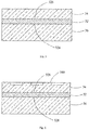
Figs. 5 and 6 show aflexible element 30 of the present disclosed. In addition to the flexible touchpad andcover layer 34, theflexible element 30 further includes asupport layer 36. Thesupport layer 36 is located on the lower surface of the flexible touchpad. Thesupport layer 36 may be located on the lower surface of the flexible touchpad by a hot press molding process or an injection molding process. In an embodiment of the present disclosure, the hot press molding process includes coating a surface of the flexible touchpad or thesupport layer 36 with a liquid adhesive and pressing one of the flexible touchpad and thesupport layer 36 to another to adhere the flexible touchpad and thesupport layer 36 with the adhesive. The injection molding process includes placing a flexible touchpad into a mold and then injecting a liquid material of the support layer at a high temperature so as to form asupport layer 36 by combining a support layer with the flexible touchpad. In other words, the process of forming thesupport layer 36 on the flexible touchpad requires heat treatment. After the heat treatment, the temperature is reduced to a room temperature, and a shrinkage stress may be generated in thesupport layer 36 due to thermal shrinkage. Therefore, the shrinkage stress generated in thesupport layer 36 may be used to reduce or offset the warping stress of the flexible touchpad. - With reference to
Fig. 7 , thermal shrinkage of thesupport layer 36 is greater than that of the flexible touchpad. The term "thermal shrinkage" as used in the present disclosure refers to a degree of shrinkage of material having a certain length from a high temperature to a low temperature. Since the thermal shrinkage of thesupport layer 36 is greater than that of the flexible touchpad, a shrinkage stress generated by thesupport layer 36 is greater than a shrinkage stress of the flexible touchpad after temperature is reduced from a high temperature to a room temperature. The ends of thesupport layer 36 and the flexible touchpad are fixed to thehousing element 20 and thus cannot be moved, and the other ends away from thehousing element 20 are in a free state. A force F1 inward (i.e. toward the barrel) is generated on a lower surface of the free end of the flexible touchpad and such a force F1 may reduce or offset the warping stress F2 of the flexible touchpad, thus preventing the warpage of the flexible touchpad. It is noted that, in this embodiment, the end, away from the barrel, of the flexible touchpad is taken as an example, but in fact, an inward force may be applied to all the lower surface of the flexible touchpad by thesupport layer 36. - In an embodiment of the present disclosure, the
support layer 36 is made of a material having a high thermal shrinkage, such as silica gel, polyvinylidene fluoride (PVDF) and polytetrafluoroethylene (PTFE). In an embodiment of the present disclosure, thesupport layer 36 is made of silica gel. Thesupport layer 36 may also be transparent so as to avoid affecting appearance of theflexible element 30. - With reference to
Fig. 8 , acover layer 34 made of silica gel is arranged on the upper surface of the flexible touchpad, and thus thecover layer 34 has a same thermal shrinkage compared to thesupport layer 36. On this basis, similar to the principle of thesupport layer 36, a force F3 inward (i.e., toward the barrel 20) may be generated to apply on the upper surface of the flexible touchpad by thecover layer 34. Such that the free end of the flexible touchpad may have a trend to be pulled inwards due to the force F3 and thus the warpage of the flexible touchpad may happen more easily. In order to counter shrinkage stress generated by thecover layer 34, a greater shrinkage stress is needed in thesupport layer 36. Therefore, a thickness of thesupport layer 36 is greater than that of thecover layer 34, so as to simultaneously cancel or reduce the shrinkage stress of thecover layer 34 and the warping stress of the flexible touchpad. Moreover, since thesupport layer 36 is thicker, a gravity generated by itself can cancel a part of the warping stress, so as to improve an effect of thesupport layer 36 for canceling or reducing the warping stress. By providing thesupport layer 36, theflexible element 30 can be in a flat state after being curled for a long time, thus improving the experience of the use. - It can be understood that the
support layer 36 may include other materials or other structures to achieve the effect of preventing or reducing the warpage. For example, thesupport layer 36 may be made of an elastic material, and it is attached to the lower surface of theflexible substrate 32 when the elastic material is in a stretched condition. On this basis, a resilience force may be generated because the elastic material has a shrinkage tendency, and such a resilience force may also reduce or prevent the warpage without the heat treatment.
Claims (19)
- A flexible device, comprising:a housing element; anda flexible element capable of rolling up in the housing element or spreading out from the housing element,wherein the flexible element comprises:a flexible substrate comprising a first surface, and a second surface supporting the flexible substrate when the flexible element is spread out, in which the first surface and the second surface are arranged oppositely to each other, anda support layer attached to the second surface of the flexible substrate, in which a force toward the housing element is generated in the support layer when the flexible element is spread out, and reduces or prevents warping of the flexible element.
- The flexible device according to claim 1, wherein the force toward the housing element is generated in the support layer due to shrinkage of the support layer when the flexible element is spread out.
- The flexible device according to claim 2, wherein thermal shrinkage of the support layer is greater than that of the flexible substrate.
- The flexible device according to claim 3, wherein the support layer is attached to the second surface of the flexible substrate by heat treatment.
- The flexible device according to claim 1, wherein the support layer is made of transparent materials.
- The flexible device according to claim 1, wherein the support layer comprises silica gel.
- The flexible device according to any one of claims 1 to 6, wherein the flexible substrate comprises a base, a protection layer, and a functional layer between the base and the protection layer, and the supporting layer is attached to the base.
- The flexible device according to claim 7, wherein the base, the protection layer and the functional layer are made of transparent materials.
- The flexible device according to claim 8, wherein the functional layer comprises an electrode layer, the first surface of the flexible substrate is a touch surface.
- The flexible device according to claim 7, wherein the flexible element further comprises a cover layer disposed on the first surface of the flexible substrate.
- The flexible device according to claim 10, wherein the cover layer has a hardness less than that of the flexible substrate.
- The flexible device according to claim 10, wherein the cover layer has a hardness less than that of the protection layer.
- The flexible device according to claim 10, wherein the cover layer has a thickness less than that of the support layer.
- The flexible device according to claim 10, wherein a shrinkage stress generated in the cover layer is less than a shrinkage stress generated in the support layer.
- The flexible device according to claim 10, wherein the cover layer and the support layer are made of the same material.
- The flexible device according to claim 10, wherein the cover layer comprises silica gel.
- The flexible device according to claim 10, wherein a plurality of protrusions is formed on a surface of the cover layer, and is operated to simulate keys of a keyboard.
- The flexible device according to any one of claims 1 to 6, wherein the housing element comprises a barrel and a reel disposed in the barrel, and the first surface of the flexible substrate bends and faces to the reel when the flexible substrate is wound around the reel.
- The flexible device according to any one of claims 1 to 6, wherein the first surface is compressed and the second surface is stretched when the flexible element is rolled up.
Applications Claiming Priority (1)
| Application Number | Priority Date | Filing Date | Title |
|---|---|---|---|
| PCT/CN2016/087426 WO2018000187A1 (en) | 2016-06-28 | 2016-06-28 | Flexible device |
Publications (2)
| Publication Number | Publication Date |
|---|---|
| EP3422328A1 true EP3422328A1 (en) | 2019-01-02 |
| EP3422328A4 EP3422328A4 (en) | 2019-10-16 |
Family
ID=60784970
Family Applications (1)
| Application Number | Title | Priority Date | Filing Date |
|---|---|---|---|
| EP16906590.1A Withdrawn EP3422328A4 (en) | 2016-06-28 | 2016-06-28 | FLEXIBLE DEVICE |
Country Status (5)
| Country | Link |
|---|---|
| US (1) | US20190043390A1 (en) |
| EP (1) | EP3422328A4 (en) |
| JP (1) | JP6735902B2 (en) |
| CN (1) | CN107636570B (en) |
| WO (1) | WO2018000187A1 (en) |
Families Citing this family (5)
| Publication number | Priority date | Publication date | Assignee | Title |
|---|---|---|---|---|
| US11003270B2 (en) * | 2019-02-13 | 2021-05-11 | Electronics And Telecommunications Research Institute | Touch screen panel |
| WO2021003668A1 (en) * | 2019-07-09 | 2021-01-14 | 深圳市柔宇科技有限公司 | Preparation method for elastic substrate |
| CN110580859A (en) * | 2019-10-14 | 2019-12-17 | 刘燕庭 | Support substrate for rollable display, rollable display device and electronic equipment |
| CN115280400A (en) * | 2020-03-11 | 2022-11-01 | 日东电工株式会社 | Front panel, optical laminate, and image display device |
| CN114446180B (en) * | 2022-02-22 | 2023-10-31 | 合肥维信诺科技有限公司 | Display panel and display device |
Family Cites Families (16)
| Publication number | Priority date | Publication date | Assignee | Title |
|---|---|---|---|---|
| JPH11109880A (en) * | 1997-10-02 | 1999-04-23 | Japan Aviation Electron Ind Ltd | Display device |
| US20030048256A1 (en) * | 2001-09-07 | 2003-03-13 | Salmon Peter C. | Computing device with roll up components |
| US20080013292A1 (en) * | 2004-03-16 | 2008-01-17 | Koninklijke Philips Electronics, N.V. | Rollable Electronic Panel Device |
| JP4607192B2 (en) * | 2006-01-06 | 2011-01-05 | シャープ株式会社 | Portable terminal device, display program, and recording medium |
| TWI283377B (en) * | 2006-04-18 | 2007-07-01 | Ind Tech Res Inst | Flexible display |
| CN101746033A (en) * | 2009-12-23 | 2010-06-23 | 成都中基国业新材料有限责任公司 | The extrusion molding manufacturing method of compound decorative plastic part |
| JP2012022519A (en) * | 2010-07-14 | 2012-02-02 | Shin Etsu Polymer Co Ltd | Input device for electronic apparatus |
| KR101531524B1 (en) * | 2011-10-31 | 2015-06-25 | 엘지전자 주식회사 | Portable keyboard |
| CN102858095A (en) * | 2012-08-27 | 2013-01-02 | 歌尔声学股份有限公司 | Supporting jig of flexible circuit board |
| KR101404628B1 (en) * | 2013-05-29 | 2014-06-11 | 김선종 | flexilbe electronic device |
| KR101547537B1 (en) * | 2013-12-06 | 2015-09-04 | 주식회사 휴비스 | High Self-crimping and Functional Conjugate Yarn and Method Preparing Same |
| CN203994723U (en) * | 2014-07-15 | 2014-12-10 | 殷海青 | 3D prints wire rod free connector |
| KR20160022434A (en) * | 2014-08-19 | 2016-03-02 | 삼성디스플레이 주식회사 | Display device |
| KR102269135B1 (en) * | 2014-10-06 | 2021-06-25 | 삼성디스플레이 주식회사 | Display apparatus |
| KR102319543B1 (en) * | 2014-10-22 | 2021-11-02 | 삼성디스플레이 주식회사 | Rollable display device, fabrication method of rollable display device and flexable display device |
| US10225936B2 (en) * | 2014-12-31 | 2019-03-05 | Shenzhen Royole Technologies Co., Ltd. | Flexible display device and electronic device |
-
2016
- 2016-06-28 CN CN201680019623.0A patent/CN107636570B/en not_active Expired - Fee Related
- 2016-06-28 WO PCT/CN2016/087426 patent/WO2018000187A1/en not_active Ceased
- 2016-06-28 JP JP2019505100A patent/JP6735902B2/en not_active Expired - Fee Related
- 2016-06-28 EP EP16906590.1A patent/EP3422328A4/en not_active Withdrawn
- 2016-06-28 US US16/085,817 patent/US20190043390A1/en not_active Abandoned
Also Published As
| Publication number | Publication date |
|---|---|
| JP6735902B2 (en) | 2020-08-05 |
| US20190043390A1 (en) | 2019-02-07 |
| CN107636570A (en) | 2018-01-26 |
| EP3422328A4 (en) | 2019-10-16 |
| WO2018000187A1 (en) | 2018-01-04 |
| JP2019514150A (en) | 2019-05-30 |
| CN107636570B (en) | 2020-10-27 |
Similar Documents
| Publication | Publication Date | Title |
|---|---|---|
| US20190043390A1 (en) | Flexible Device | |
| JP5918786B2 (en) | Electronics | |
| US20130076635A1 (en) | Membrane touch keyboard structure for notebook computers | |
| CN203299774U (en) | Touch panel and touch display panel | |
| CN202281978U (en) | Auxiliary input diaphragm and electronic device thereof | |
| CN105204687A (en) | Haptic feedback element, touch panel and display device, working method | |
| JP2018032430A (en) | Standardization of pressure sensitive key | |
| KR102353350B1 (en) | Variable display device | |
| US20130127791A1 (en) | Thumb or Finger Devices with Electrically Conductive Tips & Other Features for Use with Capacitive Touch Screens and/or Mechanical Keyboards Employed in Smartphones & Other Small Mobile Devices | |
| TW201409302A (en) | Cover structure and electronic device thereof | |
| CN107003746A (en) | Input equipment, sensor, keyboard and electronic equipment | |
| WO2015188475A1 (en) | Tactile feedback system, tactile feedback method, and touch display device | |
| US8599160B2 (en) | External touch keyboard | |
| TW201432532A (en) | Touch panel and manufacturing method thereof and touch display panel | |
| CN202404524U (en) | Press-sensing structure of touch keyboard | |
| TW201413504A (en) | Electronic apparatus and control method thereof | |
| TW201706753A (en) | Electronic device | |
| CN204790953U (en) | Touch -sensitive device | |
| US10691207B2 (en) | Display devices with virtual reprsentations of electronic devices | |
| TWI450146B (en) | Touch-controlled device with dynamic touch feeling and method thereof | |
| CN201725307U (en) | Touch keyboard structure | |
| US20110291936A1 (en) | Touch-type transparent keyboard | |
| CN104375655A (en) | Keyboard | |
| CN201540555U (en) | Input device for touch panel | |
| CN102736787A (en) | Input aids for touch panels |
Legal Events
| Date | Code | Title | Description |
|---|---|---|---|
| STAA | Information on the status of an ep patent application or granted ep patent |
Free format text: STATUS: THE INTERNATIONAL PUBLICATION HAS BEEN MADE |
|
| PUAI | Public reference made under article 153(3) epc to a published international application that has entered the european phase |
Free format text: ORIGINAL CODE: 0009012 |
|
| STAA | Information on the status of an ep patent application or granted ep patent |
Free format text: STATUS: REQUEST FOR EXAMINATION WAS MADE |
|
| 17P | Request for examination filed |
Effective date: 20180925 |
|
| AK | Designated contracting states |
Kind code of ref document: A1 Designated state(s): AL AT BE BG CH CY CZ DE DK EE ES FI FR GB GR HR HU IE IS IT LI LT LU LV MC MK MT NL NO PL PT RO RS SE SI SK SM TR |
|
| AX | Request for extension of the european patent |
Extension state: BA ME |
|
| DAV | Request for validation of the european patent (deleted) | ||
| DAX | Request for extension of the european patent (deleted) | ||
| A4 | Supplementary search report drawn up and despatched |
Effective date: 20190913 |
|
| RIC1 | Information provided on ipc code assigned before grant |
Ipc: G06F 1/16 20060101ALI20190910BHEP Ipc: G06F 3/041 20060101ALI20190910BHEP Ipc: G09F 9/30 20060101AFI20190910BHEP |
|
| STAA | Information on the status of an ep patent application or granted ep patent |
Free format text: STATUS: EXAMINATION IS IN PROGRESS |
|
| 17Q | First examination report despatched |
Effective date: 20211221 |
|
| STAA | Information on the status of an ep patent application or granted ep patent |
Free format text: STATUS: THE APPLICATION IS DEEMED TO BE WITHDRAWN |
|
| 18D | Application deemed to be withdrawn |
Effective date: 20220503 |