EP3422078A1 - Combiner positioning unit for a head-up display system, head-up display system and vehicle - Google Patents
Combiner positioning unit for a head-up display system, head-up display system and vehicle Download PDFInfo
- Publication number
- EP3422078A1 EP3422078A1 EP17305830.6A EP17305830A EP3422078A1 EP 3422078 A1 EP3422078 A1 EP 3422078A1 EP 17305830 A EP17305830 A EP 17305830A EP 3422078 A1 EP3422078 A1 EP 3422078A1
- Authority
- EP
- European Patent Office
- Prior art keywords
- combiner
- actuating
- support
- housing
- positioning unit
- Prior art date
- Legal status (The legal status is an assumption and is not a legal conclusion. Google has not performed a legal analysis and makes no representation as to the accuracy of the status listed.)
- Granted
Links
Images

Classifications
-
- G—PHYSICS
- G02—OPTICS
- G02B—OPTICAL ELEMENTS, SYSTEMS OR APPARATUS
- G02B27/00—Optical systems or apparatus not provided for by any of the groups G02B1/00 - G02B26/00, G02B30/00
- G02B27/01—Head-up displays
- G02B27/0149—Head-up displays characterised by mechanical features
-
- G—PHYSICS
- G02—OPTICS
- G02B—OPTICAL ELEMENTS, SYSTEMS OR APPARATUS
- G02B27/00—Optical systems or apparatus not provided for by any of the groups G02B1/00 - G02B26/00, G02B30/00
- G02B27/01—Head-up displays
- G02B27/0149—Head-up displays characterised by mechanical features
- G02B2027/0154—Head-up displays characterised by mechanical features with movable elements
- G02B2027/0159—Head-up displays characterised by mechanical features with movable elements with mechanical means other than scaning means for positioning the whole image
Definitions
- the present invention refers to a combiner positioning unit for a head-up display (HUD) system for usage in vehicles, comprising a combiner pivotably arranged in a housing, wherein the combiner is pivotable between a folded-in storage position and a folded-out operating position, wherein for pivoting the combiner from storage position to operating position the combiner is first shifted against a spring force of a first spring element in axial direction of the pivot axis to release the combiner from storage position and then rotated around the pivot axis in operating position by a second spring element connected to the combiner.
- HUD head-up display
- the present invention also refers to head-up display system, comprising the inventive combiner positioning unit.
- the present invention refers to a vehicle, comprising the head-up display system, comprising the inventive combiner positioning unit.
- a head-up display system usually includes a projection unit which produces a light beam intended to be directed towards a combiner in order to project images, in particular operating or driving information of a vehicle, in the form of a virtual image, in the field of view of the user, in particular a driver of a motor vehicle.
- the combiner is typically an angled flat piece of glass or plastic located directly in front of the user that redirects the projected image from the projection unit in such a way as to see the field of view and the projected image at the same time.
- Combiners may have special coatings that reflect the monochromatic light projected onto it from the projection unit while allowing all other wavelengths of light to pass through.
- a combiner positioning mechanism for a HUD system which can move a combiner between a storage position and an operating position, according to the preamble of claim 1, is known in the prior art.
- a combiner positioning system is disclosed in document US 2009/0086329 A1 .
- the positioning system is arranged on a frame including a base plate.
- a movable carrier is provided for supporting a combiner within the frame. The carrier is movable between a first end of the frame, where the combiner is in a retracted position (storage position), to a second end where the combiner is in a fully extended position (display position).
- Combiner positioning units require careful consideration to ensure the performance in all kinds of different conditions such as changing temperatures on a dashboard of a vehicle behind a windshield or vibrations during movement of the vehicle. Especially a combiner should not automatically be moved from storage position in operating position due to operational vibrations of the vehicle. A repeatable positional accuracy is also important for the combiner positioning unit, because an improperly positioned combiner will not function properly in a HUD system.
- It is an object of the present invention to provide a combiner positioning unit for a head-up display system comprising a combiner with an actuating mechanism for easily and comfortably moving the combiner between a storage position and an operating position, wherein the actuating mechanism comprises a reduced sensitivity against operating vibrations of the vehicle.
- the present invention provides combiner positioning unit for a head-up display system for usage in vehicles, comprising a housing, a combiner with a combiner support, wherein the combiner support is pivotably arranged around a pivot axis between a folded-in storage position and a folded-out operating position in the housing, and an actuating element for releasing the combiner support from the storage position, characterized in that the combiner support comprises a first locking element for engaging with a corresponding second locking element of the housing, and in storage position the first locking element is engaged with the second locking element, and by operating the actuating element, the combiner support is at least partially moved in axial direction of the pivot axis against a spring force of a first spring element, disengaging the connection of the first locking element and the second locking element, and a spring force of a second spring element connected to the combiner support pivots the combiner around the pivot axis into the operating position.
- the combiner is preferably an angled flat piece of glass or plastic.
- the combiner may have at least on one side a coating that reflects monochromatic light projected onto the combiner from a projection unit while allowing all other wavelengths of light to pass through.
- the combiner may have a curved surface to refocus an image displayed on the combiner. More preferably, the combiner is comparable to a semi-transparent mirror.
- a combiner support is a supporting and/or mounting structure for the combiner, especially for holding the combiner in the supporting and/or mounting structure.
- the combiner positioning unit comprises a housing in which the combiner support of the combiner is pivotably arranged.
- the combiner is pivotable around a pivot axis of the combiner support in such a way that the combiner can be pivoted between a folded-in storage position and a folded-out operating position.
- In storage position the combiner is folded in. That means that an image displayed on the combiner is not visible to a user.
- the combiner is aligned with the dashboard of the vehicle.
- operating position the combiner is folded out for receiving a light beam of a projector.
- the operating position is a rather upright position of the combiner with respect to the dashboard.
- the combiner positioning unit further comprises an actuating element for releasing the combiner support from storage position for pivoting the combiner support and/or the combiner in operating position.
- the combiner support comprises a first locking element for engaging with a corresponding second locking element of the housing, wherein in storage position the first locking element is engaged with the second locking element.
- the combiner support comprising the combiner is hold in storage position by engaging and/or interlocking the first locking element with the second locking element.
- the combiner support is at least partially moveably arranged in axial direction of the pivot axis against a spring force of a first spring element, wherein by operating the actuating element, the combiner support is at least partially moved in axial direction of the pivot axis against the spring force of the first spring element disengaging the connection of the first locking element and the second locking element.
- a spring force of a second spring element connected to the combiner support pivots the combiner around the pivot axis from storage position into operating position.
- the combiner for moving the combiner from storage position to operating position, the combiner is first shifted against the spring force of the first spring element in axial direction of the pivot axis to release the combiner from storage position and then rotated around the pivot axis in operating position by a second spring element connected to combiner.
- the spring force of the first spring element shifts the combiner support at least partially along the pivot axis in direction of the spring force of the first spring element.
- the combiner has to be first shifted at least partially in axial direction against the first spring element. Due to that movement, the actuating mechanism for releasing the combiner support from storage position for pivoting in operating position can comprise a reduced sensitivity against operating vibrations of the vehicle.
- the first spring element can be arranged in any manner so that the combiner support is moveable in axial direction of the pivot axis against the first spring element.
- the first spring element is arranged on the pivot axis between the combiner support and the housing.
- the spring force of the first spring element is orientated in longitudinal direction of the pivot axis.
- the first spring element is pre-loaded applying a spring force in axial direction of the pivot axis for engaging the first locking element with the second locking element.
- the combiner support can be securely positioned in storage position.
- the second spring element can be arranged in any manner according to the combiner support for moving the combiner support respectively combiner from storage position to operating position once the first locking element and the second locking element are disengaged.
- the second spring element is connected to the combiner support in a direction perpendicular to the pivot axis of the combiner support.
- a lever arm and/or lever section is arranged between the pivot axis of the combiner support and the connection point of the second spring element to the combiner support so that the spring force of the second spring element can turn the combiner support around the pivot axis.
- the second spring element is back-anchored with the housing.
- the second spring element is pre-loaded when the combiner is in storage position.
- the spring force of the pre-loaded second spring element automatically moves the combiner support in the operating position.
- the actuating element can be designed in such a way that by operating the actuating element the supporting structure is at least partially shifted in axial direction of the pivot axis against the spring force for disengaging the connection of the first locking element and the second locking element.
- the actuating element comprises an actuating button guided in a guiding hole of the housing, and an actuating wheel rotatably arranged in the housing in operating connection with the actuating button, so that the actuating wheel is at least partially rotatable around its rotational axis due to a translational movement of the actuating button, wherein the actuating wheel is in operating connection with the combiner support, so that due to the rotational movement of the actuating wheel the combiner support is at least partially moved in axial direction of the pivot axis against the spring force of the first spring element, disengaging the connection of the first locking element and the second locking element.
- the distance between the combiner support and the actuating button for manually operating the actuating button can be increased, allowing a comfortable operation of the combiner positioning unit for a user.
- the actuating button is operable against a spring force of a third spring element, wherein the third spring element is preferably arranged between the housing and a button head of the actuating button. Hence, once the actuating button is pressed and released, the actuating button is automatically moved back in the initial position by the spring force of the third spring element.
- the operating connection between the actuating button and the actuating wheel can be designed in different ways to transmit the translational movement of the actuating button on the actuating wheel.
- the operating connection between the actuating button and the actuating wheel is a toothed structure.
- the toothed structure of the actuating wheel is arranged on an outer periphery of a first projection of the actuating wheel extending in radial direction.
- the distance between the actuating wheel and the actuating button can be increased without enlarging the diameter of the actuating wheel.
- the installation space and weight of the actuating wheel can be reduced.
- the actuating button can be comfortably positioned for a user.
- the actuating wheel comprises a second projection extending in radial direction comprising an actuating cam for operating with the combiner support, wherein the actuating cam extends in axial direction of the actuating wheel.
- the second projection is preferably arranged spaced apart from the first projection and more preferably directed basically in opposite direction of the first projection.
- the actuating wheel is in operating connection with the housing so that due to an rotational movement of the actuating wheel, the actuating wheel is at least partially moved in axial direction of the rotational axis, wherein due to the axial movement of the actuating wheel the combiner support is at least partially moved in axial direction of the pivot axis against the spring force of the first spring element disengaging the connection of the first locking element and the second locking element.
- the translational move of the actuating button is transferred into a rotational movement of the actuating wheel and into a movement of the actuating wheel along its rotational axis.
- the rotational axis is preferably arranged in parallel direction to the pivot axis of the combiner support so that the radial direction of the actuating wheel is directed perpendicular to the pivot axis of the combiner support. Hence, the structural size of the combiner positioning unit in its width can be reduced.
- the actuating wheel comprises a front side arranged in a direction of the rotational axis of the actuating wheel facing the housing, wherein at least one first ramp element comprising an inclined first sliding surface with respect to the front side of the actuating wheel is arranged on the front side, and the housing comprises on its surface facing the actuating wheel at least one corresponding second ramp element comprising an inclined second sliding surface, wherein in an rotational movement of the actuating wheel relative to the housing, the inclined first sliding surface slides at least partially along the inclined second sliding surface moving the actuating element in axial direction of the rotational axis.
- the actuating wheel comprises a plurality of circumferentially arranged first ramp elements on the first side and the housing a plurality of corresponding second ramp elements.
- the actuating wheel is uniformly moved in axial direction, applying a force on the combiner support for moving respectively shifting the combiner support in axial direction of the pivot axis against the spring force of the first spring element.
- the actuating wheel is at least partially moveable in axial direction of the rotational axis against a spring force of a fourth spring element, wherein the fourth spring element is preferably arranged in longitudinal direction of the rotational axis of the actuating wheel. More preferably the fourth spring element is pre-loaded applying a spring force on the actuating wheel in axial direction to press the front side of the actuating wheel with its at least one first ramp element against the housing comprising the at least one corresponding second ramp element.
- the actuating wheel is rotated in peripheral direction and shifted in axial direction against the spring force of the fourth spring element.
- the first locking element is a locking pin and the second locking element is an engagement hole in the housing.
- the spring force of the first spring element shifts the combiner support at least partially along the pivot axis in direction of the spring force. Therefore, when manually moving the combiner from operating position to storage position, the combiner support has to be first shifted in axial direction of the pivot axis of the combiner support against the spring force of the first spring element.
- the locking pin and/or the housing surrounding the engagement hole comprises an inclined structure formed and arranged in such a manner that when the combiner is manually pivoted from operating position in storage position the locking pin slides along the inclined structure shifting the combiner support in axially direction against the spring force of the first spring element and when the locking pin is aligned with the engagement hole, the spring force of the first spring element pushes the combiner support in opposite axial direction for engaging the locking pin in the engagement hole.
- the combiner can be easily moved from operating position in storage position.
- the invention relates to a head-up display system for a vehicle, comprising a combiner positioning unit, comprising a housing, a combiner with a combiner support, wherein the combiner support is pivotably arranged around a pivot axis between a folded-in storage position and a folded-out operating position in the housing, and an actuating element for releasing the combiner support from the storage position, characterized in that the combiner support comprises a first locking element for engaging with a corresponding second locking element of the housing, and in storage position the first locking element is engaged with the second locking element, and by operating the actuating element, the combiner support is at least partially moved in axial direction of the pivot axis against a spring force of a first spring element, disengaging the connection of the first locking element and the second locking element, and a spring force of a second spring element connected to the combiner support pivots the combiner around the pivot axis into the operating position, and a projector to generate a light beam loaded with information to be displayed on the combiner in
- the projector in storage-position is at least partially covered by the combiner.
- the projector in storage position the projector can be easily protected, especially for environmental conditions like dust or the like.
- the invention relates to a vehicle comprising a head-up display, comprising a combiner positioning unit, comprising a housing, a combiner with a combiner support, wherein the combiner support is pivotably arranged around a pivot axis between a folded-in storage position and a folded-out operating position in the housing, and an actuating element for releasing the combiner support from the storage position, characterized in that the combiner support comprises a first locking element for engaging with a corresponding second locking element of the housing, and in storage position the first locking element is engaged with the second locking element, and by operating the actuating element, the combiner support is at least partially moved in axial direction of the pivot axis against a spring force of a first spring element, disengaging the connection of the first locking element and the second locking element, and a spring force of a second spring element connected to the combiner support pivots the combiner around the pivot axis into the operating position, and a projector to generate a light beam loaded with information to be displayed on the combiner
- FIG. 1 shows a schematic front view of a combiner positioning unit 10 for a head-up display system for usage in vehicles.
- a head-up display systems usually includes a projection unit which produces a light beam intended to be directed towards a combiner 12 of the combiner positioning unit 10 in order to project images, in particular operating or driving information of a vehicle, in the form of a virtual image, in the field of view of the user, in particular a driver of a motor vehicle.
- the head-up system is arranged in and/or on a dashboard between the steering wheel and the windshield of a vehicle.
- the combiner positioning unit 10 is configured for positioning the combiner 12 between a storage position and an operating position, wherein in storage position the combiner 12 is folded in, preferably to cover the projecting unit protecting it from environmental influences like dust or the like. In operating position, the combiner 12 is folded out for receiving the light beam.
- the combiner 12 is a curved flat piece of glass or plastic located directly in front of the user that redirects the projected image from the projection unit in such a way as to see the field of view and the projected image at the same time.
- the combiner 12 has a special coatings that reflect the monochromatic light projected onto it from the projection unit while allowing all other wavelengths of light to pass through.
- the combiner positioning unit 10 comprises a housing 14 and a combiner support 16 for receiving and/or holding the combiner 12.
- the combiner support 16 is pivotably arranged in the housing 14, wherein the combiner 12, mounted in the combiner support 16, can be pivoted around its pivot axis 18 between the folded-in storage position and the folded-out operating position.
- the combiner 12 is shown in storage position.
- the combiner positioning unit 10 further comprises an actuating element 20 that is in operating connection with the combiner support 16 for releasing the combiner support 16 from storage position for pivoting the combiner support 16 and the combiner 12 in operating position.
- the combiner support 16 comprises a first locking element 22 for engaging with a corresponding second locking element 24 of the housing 14, wherein in storage position the first locking element 22 is engaged with the second locking element 24 as shown in Figure 2 .
- the combiner support 16, comprising the combiner 12 is hold in storage position by engaging the first locking element 22 with the second locking element 24.
- the first locking element 22 is a locking pin and the second locking element 24 is an engagement hole in the housing 14.
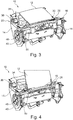
- Figure 3 shows a schematic rear view of the combiner positioning unit 10, wherein the combiner 12 is in storage position.
- the combiner support 16 is at least partially moveably arranged in axial direction of the pivot axis 18 against a spring force of a first spring element 26, wherein by operating the actuating element 20, which is indicated by the first arrow 28, the combiner support 16 is at least partially moved in axial direction of the pivot axis 18 against the spring force of the first spring element 26, disengaging the connection of the first locking element 22 and the second locking element 24.
- the movement of the combiner support 16 along the pivot axis 18 against the spring force of the first spring element 26 is indicated by a second arrow 30.
- a pre-loaded spring force of a second spring element 32 connected to the combiner support 16 as shown in Figure 1 , pivots the combiner 12 around the pivot axis 18 from storage position into operating position.
- the combiner support 16 is first shifted against the spring force of the first spring element 26 in axial direction of the pivot axis 18 to release the combiner 12 from storage position and then rotated around the pivot axis 18 in operating position by the second spring element 32 connected to combiner support 16. Due to that the actuating mechanism for releasing the combiner support 16 from storage position for rotating in operating position, the sensitivity of the combination position unit 10 against operating vibrations of the vehicle can be reduced.
- Figure 4 shows a schematic front view of the combiner positioning unit 10, wherein the combiner 12 is moved to operating position. Once the combiner 12 is positioned in operating position, the spring force of the first spring element 26 shifts the combiner support at least partially along the pivot axis 18 in direction of the spring force of the first spring element 26, which is indicated by a third arrow 34.
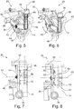
- FIGS. 5 to 8 show a detailed view of the actuating element 20.
- the actuating element 20 comprises an actuating button 36 guided in a guiding hole 38 of the housing 14, and an actuating wheel 40, rotatably arranged in the housing 14 in operating connection with the actuating button 36, so that the actuating wheel 40 is at least partially rotatable around its rotational axis 42 due to a translational movement of the actuating button 36.
- the translational movement of the actuating button 36 is indicated by the first arrow 28 pointing on a head of the actuating button 36.
- the actuating wheel 40 is in operating connection with the combiner support 16, so that due to the rotational movement of the actuating wheel 40 the combiner support 16 is at least partially moved in axial direction of the pivot axis 18 against the spring force of the first spring element 26 disengaging the connection of the first locking element 22 and the second locking element 24.
- the actuating button 36 is operable against a spring force of a third spring element 44, arranged between the housing 14 and the head of the actuating button 36. Hence, once the actuating button 36 is pressed and released, the actuating button 36 is automatically moved back in the initial position by the spring force of the third spring element 44.
- the operating connection between the actuating button 36 and the actuating wheel 40 is a toothed structure.
- the toothed structure of the actuating wheel 40 is arranged on an outer periphery of a first projection 46 of the actuating wheel 40, extending in radial direction.
- the distance between the actuating wheel 40 and the actuating button 36 can be increased without enlarging the diameter of the actuating wheel 40.
- the installation space and weight of the actuating wheel 40 can be reduced.
- the actuating button 36 can be comfortably positioned for a user.
- a second projection 48 extending in radial direction of the actuating wheel 40, comprises an actuating cam 50 for operating with the combiner support 16, wherein the actuating cam 50 extends in axial direction of the actuating wheel 40.
- the second projection 48 is arranged spaced apart from the first projection 46, especially directed basically in opposite direction of the first projection 46.
- Figures 7 and 8 show a top view of the actuating element 20.
- the actuating wheel 40 comprises a front side 52 arranged in a direction of the rotational axis 42 of the actuating wheel 40 facing the housing 14, wherein at least one first ramp element 54 comprising an inclined first sliding surface 56 with respect to the front side 52 of the actuating wheel 40 is arranged on the front side 52.
- the housing 14 comprises on its surface 58 facing the actuating wheel 40 at least one corresponding second ramp element 60 comprising an inclined second sliding surface 62, wherein in an rotational movement of the actuating wheel 40 relative to the housing 14, the inclined first sliding surface 56 slides at least partially along the inclined second sliding surface 62 moving the actuating wheel 40 in axial direction of the rotational axis 42 against a spring force of a fourth spring element 64, wherein the fourth spring element 64 is arranged in longitudinal direction of the rotational axis 42 of the actuating wheel 40.
- the fourth spring element 64 is pre-loaded applying a spring force on the actuating wheel 40 in axial direction to press the front side 52 of the actuating wheel 40 with its at least one first ramp element 54 against the housing 14 comprising the at least one corresponding second ramp element 60.
- the actuating wheel 40 is rotated in peripheral direction and shifted in axial direction against the spring force of the fourth spring element 64.
- a force is applied via the actuating cam 50 on the combiner support 16 for shifting the combiner support 16 in axial direction of the pivot axis 18 against the spring force of the first spring element 26 for disengaging the connection of the first locking element 22 and the second locking element 24.
- the second spring element 32 automatically moves the combiner support 16 and the combiner 12 in operating position.
- the actuating button 36 is released, the actuating wheel 40 is shifted back in its initial position by the fourth spring element 64.
- the actuating button 36 is moved back in its initial position by the spring force of the third spring element 44.
Landscapes
- Physics & Mathematics (AREA)
- General Physics & Mathematics (AREA)
- Optics & Photonics (AREA)
- Instrument Panels (AREA)
Abstract
Description
- The present invention refers to a combiner positioning unit for a head-up display (HUD) system for usage in vehicles, comprising a combiner pivotably arranged in a housing, wherein the combiner is pivotable between a folded-in storage position and a folded-out operating position, wherein for pivoting the combiner from storage position to operating position the combiner is first shifted against a spring force of a first spring element in axial direction of the pivot axis to release the combiner from storage position and then rotated around the pivot axis in operating position by a second spring element connected to the combiner.
- The present invention also refers to head-up display system, comprising the inventive combiner positioning unit.
- Furthermore, the present invention refers to a vehicle, comprising the head-up display system, comprising the inventive combiner positioning unit.
- A head-up display system usually includes a projection unit which produces a light beam intended to be directed towards a combiner in order to project images, in particular operating or driving information of a vehicle, in the form of a virtual image, in the field of view of the user, in particular a driver of a motor vehicle. The combiner is typically an angled flat piece of glass or plastic located directly in front of the user that redirects the projected image from the projection unit in such a way as to see the field of view and the projected image at the same time. Combiners may have special coatings that reflect the monochromatic light projected onto it from the projection unit while allowing all other wavelengths of light to pass through.
- A combiner positioning mechanism for a HUD system, which can move a combiner between a storage position and an operating position, according to the preamble of claim 1, is known in the prior art. For example a combiner positioning system is disclosed in document
US 2009/0086329 A1 . In this design, the positioning system is arranged on a frame including a base plate. A movable carrier is provided for supporting a combiner within the frame. The carrier is movable between a first end of the frame, where the combiner is in a retracted position (storage position), to a second end where the combiner is in a fully extended position (display position). - Combiner positioning units require careful consideration to ensure the performance in all kinds of different conditions such as changing temperatures on a dashboard of a vehicle behind a windshield or vibrations during movement of the vehicle. Especially a combiner should not automatically be moved from storage position in operating position due to operational vibrations of the vehicle. A repeatable positional accuracy is also important for the combiner positioning unit, because an improperly positioned combiner will not function properly in a HUD system.
- It is an object of the present invention to provide a combiner positioning unit for a head-up display system comprising a combiner with an actuating mechanism for easily and comfortably moving the combiner between a storage position and an operating position, wherein the actuating mechanism comprises a reduced sensitivity against operating vibrations of the vehicle.
- This object is achieved by the independent claims. Advantageous embodiments are given in the dependent claims, wherein each embodiment may individually or in combination be an aspect of the present invention.
- In particular, the present invention provides combiner positioning unit for a head-up display system for usage in vehicles, comprising a housing, a combiner with a combiner support, wherein the combiner support is pivotably arranged around a pivot axis between a folded-in storage position and a folded-out operating position in the housing, and an actuating element for releasing the combiner support from the storage position, characterized in that the combiner support comprises a first locking element for engaging with a corresponding second locking element of the housing, and in storage position the first locking element is engaged with the second locking element, and by operating the actuating element, the combiner support is at least partially moved in axial direction of the pivot axis against a spring force of a first spring element, disengaging the connection of the first locking element and the second locking element, and a spring force of a second spring element connected to the combiner support pivots the combiner around the pivot axis into the operating position.
- According to that invention, the combiner is preferably an angled flat piece of glass or plastic. The combiner may have at least on one side a coating that reflects monochromatic light projected onto the combiner from a projection unit while allowing all other wavelengths of light to pass through. Preferably, the combiner may have a curved surface to refocus an image displayed on the combiner. More preferably, the combiner is comparable to a semi-transparent mirror.
- A combiner support is a supporting and/or mounting structure for the combiner, especially for holding the combiner in the supporting and/or mounting structure.
- The basic idea of the invention is that the combiner positioning unit comprises a housing in which the combiner support of the combiner is pivotably arranged. The combiner is pivotable around a pivot axis of the combiner support in such a way that the combiner can be pivoted between a folded-in storage position and a folded-out operating position. In storage position, the combiner is folded in. That means that an image displayed on the combiner is not visible to a user. Preferably, when the head-up display system is used in a vehicle, in storage position the combiner is aligned with the dashboard of the vehicle. In operating position, the combiner is folded out for receiving a light beam of a projector. When used in a vehicle, the operating position is a rather upright position of the combiner with respect to the dashboard.
- The combiner positioning unit further comprises an actuating element for releasing the combiner support from storage position for pivoting the combiner support and/or the combiner in operating position. The combiner support comprises a first locking element for engaging with a corresponding second locking element of the housing, wherein in storage position the first locking element is engaged with the second locking element. Thus, the combiner support comprising the combiner is hold in storage position by engaging and/or interlocking the first locking element with the second locking element.
- The combiner support is at least partially moveably arranged in axial direction of the pivot axis against a spring force of a first spring element, wherein by operating the actuating element, the combiner support is at least partially moved in axial direction of the pivot axis against the spring force of the first spring element disengaging the connection of the first locking element and the second locking element. In this release position of the combiner support, a spring force of a second spring element connected to the combiner support pivots the combiner around the pivot axis from storage position into operating position. Hence, for moving the combiner from storage position to operating position, the combiner is first shifted against the spring force of the first spring element in axial direction of the pivot axis to release the combiner from storage position and then rotated around the pivot axis in operating position by a second spring element connected to combiner. Preferably, once the combiner is positioned in operating position, the spring force of the first spring element shifts the combiner support at least partially along the pivot axis in direction of the spring force of the first spring element. Hence, for moving the combiner from storage position to operating position, the combiner has to be first shifted at least partially in axial direction against the first spring element. Due to that movement, the actuating mechanism for releasing the combiner support from storage position for pivoting in operating position can comprise a reduced sensitivity against operating vibrations of the vehicle.
- Generally, the first spring element can be arranged in any manner so that the combiner support is moveable in axial direction of the pivot axis against the first spring element. According to a preferred embodiment of the invention, the first spring element is arranged on the pivot axis between the combiner support and the housing. Hence, the spring force of the first spring element is orientated in longitudinal direction of the pivot axis. Preferably, in storage position of the combiner support, the first spring element is pre-loaded applying a spring force in axial direction of the pivot axis for engaging the first locking element with the second locking element. Hence, the combiner support can be securely positioned in storage position.
- The second spring element can be arranged in any manner according to the combiner support for moving the combiner support respectively combiner from storage position to operating position once the first locking element and the second locking element are disengaged. According to a preferred embodiment of the invention, the second spring element is connected to the combiner support in a direction perpendicular to the pivot axis of the combiner support. A lever arm and/or lever section is arranged between the pivot axis of the combiner support and the connection point of the second spring element to the combiner support so that the spring force of the second spring element can turn the combiner support around the pivot axis. Preferably, the second spring element is back-anchored with the housing.
- According to a preferred embodiment of the invention, the second spring element is pre-loaded when the combiner is in storage position. Hence, once the supporting structure is at least partially shifted in axial direction of the pivot axis against the spring force of the first spring element for disengaging the connection of the first locking element, the spring force of the pre-loaded second spring element automatically moves the combiner support in the operating position.
- Generally, the actuating element can be designed in such a way that by operating the actuating element the supporting structure is at least partially shifted in axial direction of the pivot axis against the spring force for disengaging the connection of the first locking element and the second locking element. According to a preferred embodiment of the invention, the actuating element comprises an actuating button guided in a guiding hole of the housing, and an actuating wheel rotatably arranged in the housing in operating connection with the actuating button, so that the actuating wheel is at least partially rotatable around its rotational axis due to a translational movement of the actuating button, wherein the actuating wheel is in operating connection with the combiner support, so that due to the rotational movement of the actuating wheel the combiner support is at least partially moved in axial direction of the pivot axis against the spring force of the first spring element, disengaging the connection of the first locking element and the second locking element. Hence, due to the transmission of the translational movement of the actuating button on the actuating wheel, which is in operating contact with the combiner support, the distance between the combiner support and the actuating button for manually operating the actuating button can be increased, allowing a comfortable operation of the combiner positioning unit for a user.
- According to a preferred embodiment of the invention, the actuating button is operable against a spring force of a third spring element, wherein the third spring element is preferably arranged between the housing and a button head of the actuating button. Hence, once the actuating button is pressed and released, the actuating button is automatically moved back in the initial position by the spring force of the third spring element.
- The operating connection between the actuating button and the actuating wheel can be designed in different ways to transmit the translational movement of the actuating button on the actuating wheel. According to a preferred embodiment of the invention, the operating connection between the actuating button and the actuating wheel is a toothed structure. Hence, a reliable and robust operating connection for an interaction of the actuating button and the actuating wheel is provided.
- According to a preferred embodiment of the invention, the toothed structure of the actuating wheel is arranged on an outer periphery of a first projection of the actuating wheel extending in radial direction. Hence, the distance between the actuating wheel and the actuating button can be increased without enlarging the diameter of the actuating wheel. Thus, the installation space and weight of the actuating wheel can be reduced. By enlarging the distance between the actuating wheel and the actuating button, the actuating button can be comfortably positioned for a user.
- In a preferred embodiment of the invention, the actuating wheel comprises a second projection extending in radial direction comprising an actuating cam for operating with the combiner support, wherein the actuating cam extends in axial direction of the actuating wheel. The second projection is preferably arranged spaced apart from the first projection and more preferably directed basically in opposite direction of the first projection.
- According to a preferred embodiment of the invention, the actuating wheel is in operating connection with the housing so that due to an rotational movement of the actuating wheel, the actuating wheel is at least partially moved in axial direction of the rotational axis, wherein due to the axial movement of the actuating wheel the combiner support is at least partially moved in axial direction of the pivot axis against the spring force of the first spring element disengaging the connection of the first locking element and the second locking element. Hence, the translational move of the actuating button is transferred into a rotational movement of the actuating wheel and into a movement of the actuating wheel along its rotational axis. The rotational axis is preferably arranged in parallel direction to the pivot axis of the combiner support so that the radial direction of the actuating wheel is directed perpendicular to the pivot axis of the combiner support. Hence, the structural size of the combiner positioning unit in its width can be reduced.
- In a preferred embodiment of the invention, the actuating wheel comprises a front side arranged in a direction of the rotational axis of the actuating wheel facing the housing, wherein at least one first ramp element comprising an inclined first sliding surface with respect to the front side of the actuating wheel is arranged on the front side, and the housing comprises on its surface facing the actuating wheel at least one corresponding second ramp element comprising an inclined second sliding surface, wherein in an rotational movement of the actuating wheel relative to the housing, the inclined first sliding surface slides at least partially along the inclined second sliding surface moving the actuating element in axial direction of the rotational axis. Preferably, the actuating wheel comprises a plurality of circumferentially arranged first ramp elements on the first side and the housing a plurality of corresponding second ramp elements. Hence, while rotating the actuating wheel, the actuating wheel is uniformly moved in axial direction, applying a force on the combiner support for moving respectively shifting the combiner support in axial direction of the pivot axis against the spring force of the first spring element.
- According to a preferred embodiment of the invention, the actuating wheel is at least partially moveable in axial direction of the rotational axis against a spring force of a fourth spring element, wherein the fourth spring element is preferably arranged in longitudinal direction of the rotational axis of the actuating wheel. More preferably the fourth spring element is pre-loaded applying a spring force on the actuating wheel in axial direction to press the front side of the actuating wheel with its at least one first ramp element against the housing comprising the at least one corresponding second ramp element. Hence, when operating the actuating button for disengaging the connection of the first locking element and the second locking element, the actuating wheel is rotated in peripheral direction and shifted in axial direction against the spring force of the fourth spring element. Due to the movement of the actuating wheel in axial direction a force is applied on the combiner support for shifting the combiner support in axial direction of the pivot axis against the spring force of the first spring element for disengaging the connection of the first locking element and the second locking element. When the actuating button is released, the spring force of the fourth spring will shift the actuating wheel back in its initial position.
- In a preferred embodiment of the invention, the first locking element is a locking pin and the second locking element is an engagement hole in the housing. Hence, a simple an inexpensive first and second locking element is provided.
- Usually, once the combiner is positioned in operating position, the spring force of the first spring element shifts the combiner support at least partially along the pivot axis in direction of the spring force. Therefore, when manually moving the combiner from operating position to storage position, the combiner support has to be first shifted in axial direction of the pivot axis of the combiner support against the spring force of the first spring element. According to a preferred embodiment of the invention, the locking pin and/or the housing surrounding the engagement hole comprises an inclined structure formed and arranged in such a manner that when the combiner is manually pivoted from operating position in storage position the locking pin slides along the inclined structure shifting the combiner support in axially direction against the spring force of the first spring element and when the locking pin is aligned with the engagement hole, the spring force of the first spring element pushes the combiner support in opposite axial direction for engaging the locking pin in the engagement hole. Hence, the combiner can be easily moved from operating position in storage position.
- The invention relates to a head-up display system for a vehicle, comprising a combiner positioning unit, comprising a housing, a combiner with a combiner support, wherein the combiner support is pivotably arranged around a pivot axis between a folded-in storage position and a folded-out operating position in the housing, and an actuating element for releasing the combiner support from the storage position, characterized in that the combiner support comprises a first locking element for engaging with a corresponding second locking element of the housing, and in storage position the first locking element is engaged with the second locking element, and by operating the actuating element, the combiner support is at least partially moved in axial direction of the pivot axis against a spring force of a first spring element, disengaging the connection of the first locking element and the second locking element, and a spring force of a second spring element connected to the combiner support pivots the combiner around the pivot axis into the operating position, and a projector to generate a light beam loaded with information to be displayed on the combiner in operation position.
- According to a preferred embodiment of the invention, in storage-position the projector is at least partially covered by the combiner. Hence, in storage position the projector can be easily protected, especially for environmental conditions like dust or the like.
- Furthermore, the invention relates to a vehicle comprising a head-up display, comprising a combiner positioning unit, comprising a housing, a combiner with a combiner support, wherein the combiner support is pivotably arranged around a pivot axis between a folded-in storage position and a folded-out operating position in the housing, and an actuating element for releasing the combiner support from the storage position, characterized in that the combiner support comprises a first locking element for engaging with a corresponding second locking element of the housing, and in storage position the first locking element is engaged with the second locking element, and by operating the actuating element, the combiner support is at least partially moved in axial direction of the pivot axis against a spring force of a first spring element, disengaging the connection of the first locking element and the second locking element, and a spring force of a second spring element connected to the combiner support pivots the combiner around the pivot axis into the operating position, and a projector to generate a light beam loaded with information to be displayed on the combiner in operation position.
- These and other aspects of the invention will be apparent from and elucidated with reference to the embodiments described hereinafter.
- In the drawings:
- Fig. 1
- shows a schematic front view of a combiner positioning unit comprising a combiner in storage position, according to a preferred embodiment of the invention,
- Fig. 2
- shows a detailed view of the a first locking element and a second locking element for interlocking the combiner support in storage position, according to the preferred embodiment of the invention,
- Fig. 3
- shows a schematic rear view of the combiner positioning unit, wherein the combiner is in storage position, according to the preferred embodiment of the invention,
- Fig. 4
- shows a schematic rear view of the combiner positioning unit, wherein the combiner is moved to operating position, according to the preferred embodiment of the invention,
- Fig. 5
- shows a view of an actuating element for releasing a combiner support of the combiner from storage position in an initial position, according to the preferred embodiment of the invention,
- Fig. 6
- shows a view of the actuating element for releasing the combiner support from storage position in an actuating position, according to the preferred embodiment of the invention,
- Fig. 7
- shows a top view of the actuating element in the initial position, according to the preferred embodiment of the invention,
- Fig. 8
- shows a top view of the actuating element in actuating position, according to the preferred embodiment of the invention.
-
Figure 1 shows a schematic front view of acombiner positioning unit 10 for a head-up display system for usage in vehicles. A head-up display systems usually includes a projection unit which produces a light beam intended to be directed towards acombiner 12 of thecombiner positioning unit 10 in order to project images, in particular operating or driving information of a vehicle, in the form of a virtual image, in the field of view of the user, in particular a driver of a motor vehicle. Preferably, the head-up system is arranged in and/or on a dashboard between the steering wheel and the windshield of a vehicle. Thecombiner positioning unit 10 is configured for positioning thecombiner 12 between a storage position and an operating position, wherein in storage position thecombiner 12 is folded in, preferably to cover the projecting unit protecting it from environmental influences like dust or the like. In operating position, thecombiner 12 is folded out for receiving the light beam. - The
combiner 12 is a curved flat piece of glass or plastic located directly in front of the user that redirects the projected image from the projection unit in such a way as to see the field of view and the projected image at the same time. Thecombiner 12 has a special coatings that reflect the monochromatic light projected onto it from the projection unit while allowing all other wavelengths of light to pass through. - The
combiner positioning unit 10 comprises ahousing 14 and acombiner support 16 for receiving and/or holding thecombiner 12. Thecombiner support 16 is pivotably arranged in thehousing 14, wherein thecombiner 12, mounted in thecombiner support 16, can be pivoted around itspivot axis 18 between the folded-in storage position and the folded-out operating position. InFigure 1 , thecombiner 12 is shown in storage position. Thecombiner positioning unit 10 further comprises anactuating element 20 that is in operating connection with thecombiner support 16 for releasing thecombiner support 16 from storage position for pivoting thecombiner support 16 and thecombiner 12 in operating position. Thecombiner support 16 comprises afirst locking element 22 for engaging with a correspondingsecond locking element 24 of thehousing 14, wherein in storage position thefirst locking element 22 is engaged with thesecond locking element 24 as shown inFigure 2 . Thus, thecombiner support 16, comprising thecombiner 12 is hold in storage position by engaging thefirst locking element 22 with thesecond locking element 24. Thefirst locking element 22 is a locking pin and thesecond locking element 24 is an engagement hole in thehousing 14. -
Figure 3 shows a schematic rear view of thecombiner positioning unit 10, wherein thecombiner 12 is in storage position. Thecombiner support 16 is at least partially moveably arranged in axial direction of thepivot axis 18 against a spring force of afirst spring element 26, wherein by operating theactuating element 20, which is indicated by thefirst arrow 28, thecombiner support 16 is at least partially moved in axial direction of thepivot axis 18 against the spring force of thefirst spring element 26, disengaging the connection of thefirst locking element 22 and thesecond locking element 24. The movement of thecombiner support 16 along thepivot axis 18 against the spring force of thefirst spring element 26 is indicated by asecond arrow 30. In release position of thecombiner support 16, a pre-loaded spring force of asecond spring element 32, connected to thecombiner support 16 as shown inFigure 1 , pivots thecombiner 12 around thepivot axis 18 from storage position into operating position. Hence, for moving thecombiner support 16 with thecombiner 12 from storage position to operating position, thecombiner support 16 is first shifted against the spring force of thefirst spring element 26 in axial direction of thepivot axis 18 to release thecombiner 12 from storage position and then rotated around thepivot axis 18 in operating position by thesecond spring element 32 connected tocombiner support 16. Due to that the actuating mechanism for releasing thecombiner support 16 from storage position for rotating in operating position, the sensitivity of thecombination position unit 10 against operating vibrations of the vehicle can be reduced. -
Figure 4 shows a schematic front view of thecombiner positioning unit 10, wherein thecombiner 12 is moved to operating position. Once thecombiner 12 is positioned in operating position, the spring force of thefirst spring element 26 shifts the combiner support at least partially along thepivot axis 18 in direction of the spring force of thefirst spring element 26, which is indicated by athird arrow 34. -
Figures 5 to 8 show a detailed view of theactuating element 20. Theactuating element 20 comprises anactuating button 36 guided in a guidinghole 38 of thehousing 14, and anactuating wheel 40, rotatably arranged in thehousing 14 in operating connection with theactuating button 36, so that theactuating wheel 40 is at least partially rotatable around itsrotational axis 42 due to a translational movement of theactuating button 36. The translational movement of theactuating button 36 is indicated by thefirst arrow 28 pointing on a head of theactuating button 36. Theactuating wheel 40 is in operating connection with thecombiner support 16, so that due to the rotational movement of theactuating wheel 40 thecombiner support 16 is at least partially moved in axial direction of thepivot axis 18 against the spring force of thefirst spring element 26 disengaging the connection of thefirst locking element 22 and thesecond locking element 24. - The
actuating button 36 is operable against a spring force of athird spring element 44, arranged between thehousing 14 and the head of theactuating button 36. Hence, once theactuating button 36 is pressed and released, theactuating button 36 is automatically moved back in the initial position by the spring force of thethird spring element 44. - The operating connection between the
actuating button 36 and theactuating wheel 40 is a toothed structure. The toothed structure of theactuating wheel 40 is arranged on an outer periphery of afirst projection 46 of theactuating wheel 40, extending in radial direction. Hence, the distance between theactuating wheel 40 and theactuating button 36 can be increased without enlarging the diameter of theactuating wheel 40. Thus, the installation space and weight of theactuating wheel 40 can be reduced. By enlarging the distance between theactuating wheel 40 and theactuating button 36, theactuating button 36 can be comfortably positioned for a user. - A
second projection 48, extending in radial direction of theactuating wheel 40, comprises anactuating cam 50 for operating with thecombiner support 16, wherein theactuating cam 50 extends in axial direction of theactuating wheel 40. Thesecond projection 48 is arranged spaced apart from thefirst projection 46, especially directed basically in opposite direction of thefirst projection 46. -
Figures 7 and 8 show a top view of theactuating element 20. Theactuating wheel 40 comprises afront side 52 arranged in a direction of therotational axis 42 of theactuating wheel 40 facing thehousing 14, wherein at least onefirst ramp element 54 comprising an inclined first slidingsurface 56 with respect to thefront side 52 of theactuating wheel 40 is arranged on thefront side 52. Thehousing 14 comprises on itssurface 58 facing theactuating wheel 40 at least one correspondingsecond ramp element 60 comprising an inclined second slidingsurface 62, wherein in an rotational movement of theactuating wheel 40 relative to thehousing 14, the inclined first slidingsurface 56 slides at least partially along the inclined second slidingsurface 62 moving theactuating wheel 40 in axial direction of therotational axis 42 against a spring force of afourth spring element 64, wherein thefourth spring element 64 is arranged in longitudinal direction of therotational axis 42 of theactuating wheel 40. Thefourth spring element 64 is pre-loaded applying a spring force on theactuating wheel 40 in axial direction to press thefront side 52 of theactuating wheel 40 with its at least onefirst ramp element 54 against thehousing 14 comprising the at least one correspondingsecond ramp element 60. Hence, when operating theactuating button 36 for disengaging the connection of thefirst locking element 22 and thesecond locking element 24, theactuating wheel 40 is rotated in peripheral direction and shifted in axial direction against the spring force of thefourth spring element 64. Due to the movement of theactuating wheel 40 in axial direction a force is applied via theactuating cam 50 on thecombiner support 16 for shifting thecombiner support 16 in axial direction of thepivot axis 18 against the spring force of thefirst spring element 26 for disengaging the connection of thefirst locking element 22 and thesecond locking element 24. Thesecond spring element 32 automatically moves thecombiner support 16 and thecombiner 12 in operating position. When theactuating button 36 is released, theactuating wheel 40 is shifted back in its initial position by thefourth spring element 64. Theactuating button 36 is moved back in its initial position by the spring force of thethird spring element 44.Reference signs list Combiner positioning unit 10 Combiner 12 Housing 14 Combiner support 16 Pivot axis of combiner support 18 Actuating element 20 First locking element 22 Second locking element 24 Frist spring element 26 First arrow 28 Second arrow 30 Second spring element 32 Third arrow 34 Actuating button 36 Guiding hole 38 Actuating wheel 40 Rotational axis 42 Third spring element 44 First projection 46 Second projection 48 Actuating cam 50 Front side 52 Frist ramp element 54 First sliding surface 56 Surface of the housing 58 Second ramp element 60 Second sliding surface 62 Fourth spring element 64
Claims (16)
- Combiner positioning unit (10) for a head-up display system for usage in vehicles, comprising
a housing (14),
a combiner (12) with a combiner support (16), wherein the combiner support (16) is pivotably arranged around a pivot axis (18) between a folded-in storage position and a folded-out operating position in the housing (14), and
an actuating element (20) for releasing the combiner support (16) from the storage position, characterized in that
the combiner support (16) comprises a first locking element (22) for engaging with a corresponding second locking element (24) of the housing (14), and in the storage position the first locking element (22) is engaged with the second locking element (24), and
by operating the actuating element (20), the combiner support (16) is at least partially moved in axial direction of the pivot axis (18) against a spring force of a first spring element (26), disengaging the connection of the first locking element (22) and the second locking element (24), and a spring force of a second spring element (32) connected to the combiner support (16) pivots the combiner (12) around the pivot axis (18) into the operating position. - Combiner positioning unit according to claim 1, characterized in that the first spring element (26) is arranged on the pivot axis (18) between the combiner support (16) and the housing (14).
- Combiner positioning unit according to claim 1 or 2, characterized in that the second spring element (32) is connected to the combiner support (16) in a direction perpendicular to the pivot axis (18) of the combiner support (16).
- Combiner positioning unit according to one of the claims 1 to 3, characterized in that the second spring element (32) is pre-loaded when the combiner (12) is in storage position.
- Combiner positioning unit according to one of the claims 1 to 4, characterized in that the actuating element (20) comprises
an actuating button (36) guided in a guiding hole (38) of the housing (14) and
an actuating wheel (40) rotatably arranged in the housing (14) and in operating connection with the actuating button (36), so that
the actuating wheel (40) is at least partially rotatable around its rotational axis (42) due to a translational movement of the actuating button (36), wherein the actuating wheel (40) is in operating connection with the combiner support (16), so that due to the rotational movement of the actuating wheel (40) the combiner support (16) is at least partially moved in axial direction of the pivot axis (18) against the spring force of the first spring element (26) disengaging the connection of the first locking element (22) and the second locking element (24). - Combiner positioning unit according to claim 5, characterized in that the actuating button (36) is operable against a spring force of a third spring element (44), preferably arranged between the housing (14) and a button head of the actuating button (36).
- Combiner positioning unit according to claim 5 or 6, characterized in that the operating connection between the actuating button (36) and the actuating wheel (40) is a toothed structure.
- Combiner positioning unit according to claim 7, characterized in that the toothed structure of the actuating wheel (40) is arranged on an outer periphery of a first projection (46) of the actuating wheel (40) extending in radial direction.
- Combiner positioning unit according to one of the claims 5 to 8, characterized in that the actuating wheel (40) comprises a second projection (48) extending in radial direction comprising an actuating cam (50) for operating with the combiner support (16), wherein the actuating cam (50) extends in axial direction of the actuating wheel (40).
- Combiner positioning unit according to one of the claims 5 to 9, characterized in that the actuating wheel (40) is in operating connection with the housing (14) so that due to an rotational movement of the actuating wheel (40), the actuating wheel (40) is at least partially moved in axial direction of the rotational axis (42), wherein due to the axial movement of the actuating wheel (40) the combiner support (16) is at least partially moved in axial direction of the pivot axis (18) against the spring force of the first spring element (26) disengaging the connection of the first locking element (22) and the second locking element (24).
- Combiner positioning unit according to one of the claims 5 to 10, characterized in that the actuating wheel (40) comprises a front side (52) arranged in direction of the rotational axis (42) of the actuating wheel (40) facing the housing (14), wherein at least one first ramp element (54) comprising an inclined first sliding surface (56) with respect to the front side (52) of the actuating wheel (40) is arranged on the front side (52), and the housing (14) comprises on its surface (58) facing the actuating wheel (40) at least one corresponding second ramp element (60) comprising an inclined second sliding surface (62), wherein in an rotational movement of the actuating wheel (40) relative to the housing (14), the inclined first sliding surface (56) slides at least partially along the inclined second sliding surface (62) moving the actuating wheel (40) in axial direction of the rotational axis (42).
- Combiner positioning unit according to claims 10 or 11, wherein the actuating wheel (40) is at least partially moveable in axial direction of the rotational axis (42) against a spring force of a fourth spring element (64), wherein the fourth spring element (64) is preferably arranged in longitudinal direction of the rotational axis (42) of the actuating wheel (40).
- Combiner positioning unit according to one of the previous claims, characterized in that the first locking element (22) is a locking pin and the second locking element (24) is an engagement hole in the housing (14).
- Combiner positioning unit according to claim 13, characterized in that the locking pin and/or the housing (14) surrounding the engagement hole comprises an inclined structure formed and arranged in such a manner that when the combiner (12) is manually pivoted from operating position in storage position the locking pin slides along the inclined structure shifting the combiner support (16) in axially direction against the spring force of the first spring element (26) and when the locking pin is aligned with the engagement hole, the spring force of the first spring element (26) shifts the combiner support 16 in axial direction for engaging the locking pin in the engagement hole.
- Head-up display system for a vehicle comprising
a combiner positioning unit (10) according to one of the previous claims, and
a projector to generate a light beam loaded with information to be displayed on the combiner (12). - Vehicle comprising a head-up display system according to claim 15.
Priority Applications (2)
| Application Number | Priority Date | Filing Date | Title |
|---|---|---|---|
| EP17305830.6A EP3422078B1 (en) | 2017-06-30 | 2017-06-30 | Combiner positioning unit for a head-up display system, head-up display system and vehicle |
| PCT/EP2018/067131 WO2019002303A1 (en) | 2017-06-30 | 2018-06-26 | Combiner positioning unit for a head-up display system, head-up display system and vehicle |
Applications Claiming Priority (1)
| Application Number | Priority Date | Filing Date | Title |
|---|---|---|---|
| EP17305830.6A EP3422078B1 (en) | 2017-06-30 | 2017-06-30 | Combiner positioning unit for a head-up display system, head-up display system and vehicle |
Publications (2)
| Publication Number | Publication Date |
|---|---|
| EP3422078A1 true EP3422078A1 (en) | 2019-01-02 |
| EP3422078B1 EP3422078B1 (en) | 2020-12-23 |
Family
ID=59383523
Family Applications (1)
| Application Number | Title | Priority Date | Filing Date |
|---|---|---|---|
| EP17305830.6A Active EP3422078B1 (en) | 2017-06-30 | 2017-06-30 | Combiner positioning unit for a head-up display system, head-up display system and vehicle |
Country Status (2)
| Country | Link |
|---|---|
| EP (1) | EP3422078B1 (en) |
| WO (1) | WO2019002303A1 (en) |
Citations (3)
| Publication number | Priority date | Publication date | Assignee | Title |
|---|---|---|---|---|
| US5381267A (en) * | 1993-04-12 | 1995-01-10 | Hughes Aircraft Company | Movable head-up-display (HUD) combiner assembly including locking linkage mechanism |
| US20090086329A1 (en) | 2007-09-28 | 2009-04-02 | Jabil Circuit, Inc. | Positioning system for a combiner in a head up display |
| WO2010136572A2 (en) * | 2009-05-29 | 2010-12-02 | Thales | Head-up display |
-
2017
- 2017-06-30 EP EP17305830.6A patent/EP3422078B1/en active Active
-
2018
- 2018-06-26 WO PCT/EP2018/067131 patent/WO2019002303A1/en not_active Ceased
Patent Citations (3)
| Publication number | Priority date | Publication date | Assignee | Title |
|---|---|---|---|---|
| US5381267A (en) * | 1993-04-12 | 1995-01-10 | Hughes Aircraft Company | Movable head-up-display (HUD) combiner assembly including locking linkage mechanism |
| US20090086329A1 (en) | 2007-09-28 | 2009-04-02 | Jabil Circuit, Inc. | Positioning system for a combiner in a head up display |
| WO2010136572A2 (en) * | 2009-05-29 | 2010-12-02 | Thales | Head-up display |
Also Published As
| Publication number | Publication date |
|---|---|
| WO2019002303A1 (en) | 2019-01-03 |
| EP3422078B1 (en) | 2020-12-23 |
Similar Documents
| Publication | Publication Date | Title |
|---|---|---|
| EP2769258B1 (en) | Combiner positioning system | |
| EP2784570B1 (en) | Head-up display system | |
| US10394026B2 (en) | Head-up display combiner positioning and locking system | |
| US20120176683A1 (en) | Combiner positioning system for head-up display | |
| US20040239155A1 (en) | Vehicle seat back provided with a television monitor, and a vehicle seat including such a seat back | |
| US20190107717A1 (en) | Head-up display system | |
| US10737603B2 (en) | Headrest assembly | |
| EP3185062B1 (en) | Head-up display | |
| EP2994350B1 (en) | A pivot mechanism for a vehicle external rear view mirror assembly | |
| US20180373034A1 (en) | Display device | |
| US20150097953A1 (en) | Deployable camera system | |
| EP3592607B1 (en) | Display mirror toggle paddle | |
| KR20230075461A (en) | Actuators for folding and adjusting | |
| EP3422078B1 (en) | Combiner positioning unit for a head-up display system, head-up display system and vehicle | |
| EP0767086B1 (en) | A dual rear view mirror assembly | |
| US20030165025A1 (en) | Head-up display with an adjusting device for a mirror | |
| EP2955562B1 (en) | Head-up display system with a drive mechanism to move a cover to protect a combiner | |
| EP2479598B1 (en) | Positioning system for head-UP display | |
| US6059244A (en) | Convertible container holding assembly | |
| EP3422077A1 (en) | Combiner positioning unit for a head-up display system, and vehicle | |
| JP2014015070A (en) | Vehicular display | |
| JP3718972B2 (en) | Open / close type reflective display | |
| KR20220169297A (en) | Parking apparatus for vehicle | |
| JP2010066576A (en) | Camera system, camera and lens barrel | |
| JP2011154112A (en) | Imaging apparatus |
Legal Events
| Date | Code | Title | Description |
|---|---|---|---|
| PUAI | Public reference made under article 153(3) epc to a published international application that has entered the european phase |
Free format text: ORIGINAL CODE: 0009012 |
|
| STAA | Information on the status of an ep patent application or granted ep patent |
Free format text: STATUS: THE APPLICATION HAS BEEN PUBLISHED |
|
| AK | Designated contracting states |
Kind code of ref document: A1 Designated state(s): AL AT BE BG CH CY CZ DE DK EE ES FI FR GB GR HR HU IE IS IT LI LT LU LV MC MK MT NL NO PL PT RO RS SE SI SK SM TR |
|
| AX | Request for extension of the european patent |
Extension state: BA ME |
|
| STAA | Information on the status of an ep patent application or granted ep patent |
Free format text: STATUS: REQUEST FOR EXAMINATION WAS MADE |
|
| 17P | Request for examination filed |
Effective date: 20190628 |
|
| RBV | Designated contracting states (corrected) |
Designated state(s): AL AT BE BG CH CY CZ DE DK EE ES FI FR GB GR HR HU IE IS IT LI LT LU LV MC MK MT NL NO PL PT RO RS SE SI SK SM TR |
|
| GRAP | Despatch of communication of intention to grant a patent |
Free format text: ORIGINAL CODE: EPIDOSNIGR1 |
|
| STAA | Information on the status of an ep patent application or granted ep patent |
Free format text: STATUS: GRANT OF PATENT IS INTENDED |
|
| INTG | Intention to grant announced |
Effective date: 20200916 |
|
| GRAS | Grant fee paid |
Free format text: ORIGINAL CODE: EPIDOSNIGR3 |
|
| GRAA | (expected) grant |
Free format text: ORIGINAL CODE: 0009210 |
|
| STAA | Information on the status of an ep patent application or granted ep patent |
Free format text: STATUS: THE PATENT HAS BEEN GRANTED |
|
| AK | Designated contracting states |
Kind code of ref document: B1 Designated state(s): AL AT BE BG CH CY CZ DE DK EE ES FI FR GB GR HR HU IE IS IT LI LT LU LV MC MK MT NL NO PL PT RO RS SE SI SK SM TR |
|
| REG | Reference to a national code |
Ref country code: GB Ref legal event code: FG4D |
|
| REG | Reference to a national code |
Ref country code: DE Ref legal event code: R096 Ref document number: 602017029939 Country of ref document: DE |
|
| REG | Reference to a national code |
Ref country code: AT Ref legal event code: REF Ref document number: 1348297 Country of ref document: AT Kind code of ref document: T Effective date: 20210115 |
|
| REG | Reference to a national code |
Ref country code: IE Ref legal event code: FG4D |
|
| PG25 | Lapsed in a contracting state [announced via postgrant information from national office to epo] |
Ref country code: NO Free format text: LAPSE BECAUSE OF FAILURE TO SUBMIT A TRANSLATION OF THE DESCRIPTION OR TO PAY THE FEE WITHIN THE PRESCRIBED TIME-LIMIT Effective date: 20210323 Ref country code: RS Free format text: LAPSE BECAUSE OF FAILURE TO SUBMIT A TRANSLATION OF THE DESCRIPTION OR TO PAY THE FEE WITHIN THE PRESCRIBED TIME-LIMIT Effective date: 20201223 Ref country code: GR Free format text: LAPSE BECAUSE OF FAILURE TO SUBMIT A TRANSLATION OF THE DESCRIPTION OR TO PAY THE FEE WITHIN THE PRESCRIBED TIME-LIMIT Effective date: 20210324 Ref country code: FI Free format text: LAPSE BECAUSE OF FAILURE TO SUBMIT A TRANSLATION OF THE DESCRIPTION OR TO PAY THE FEE WITHIN THE PRESCRIBED TIME-LIMIT Effective date: 20201223 |
|
| REG | Reference to a national code |
Ref country code: AT Ref legal event code: MK05 Ref document number: 1348297 Country of ref document: AT Kind code of ref document: T Effective date: 20201223 |
|
| REG | Reference to a national code |
Ref country code: NL Ref legal event code: MP Effective date: 20201223 |
|
| PG25 | Lapsed in a contracting state [announced via postgrant information from national office to epo] |
Ref country code: SE Free format text: LAPSE BECAUSE OF FAILURE TO SUBMIT A TRANSLATION OF THE DESCRIPTION OR TO PAY THE FEE WITHIN THE PRESCRIBED TIME-LIMIT Effective date: 20201223 Ref country code: BG Free format text: LAPSE BECAUSE OF FAILURE TO SUBMIT A TRANSLATION OF THE DESCRIPTION OR TO PAY THE FEE WITHIN THE PRESCRIBED TIME-LIMIT Effective date: 20210323 Ref country code: LV Free format text: LAPSE BECAUSE OF FAILURE TO SUBMIT A TRANSLATION OF THE DESCRIPTION OR TO PAY THE FEE WITHIN THE PRESCRIBED TIME-LIMIT Effective date: 20201223 |
|
| PG25 | Lapsed in a contracting state [announced via postgrant information from national office to epo] |
Ref country code: HR Free format text: LAPSE BECAUSE OF FAILURE TO SUBMIT A TRANSLATION OF THE DESCRIPTION OR TO PAY THE FEE WITHIN THE PRESCRIBED TIME-LIMIT Effective date: 20201223 Ref country code: NL Free format text: LAPSE BECAUSE OF FAILURE TO SUBMIT A TRANSLATION OF THE DESCRIPTION OR TO PAY THE FEE WITHIN THE PRESCRIBED TIME-LIMIT Effective date: 20201223 |
|
| REG | Reference to a national code |
Ref country code: LT Ref legal event code: MG9D |
|
| PG25 | Lapsed in a contracting state [announced via postgrant information from national office to epo] |
Ref country code: SM Free format text: LAPSE BECAUSE OF FAILURE TO SUBMIT A TRANSLATION OF THE DESCRIPTION OR TO PAY THE FEE WITHIN THE PRESCRIBED TIME-LIMIT Effective date: 20201223 Ref country code: LT Free format text: LAPSE BECAUSE OF FAILURE TO SUBMIT A TRANSLATION OF THE DESCRIPTION OR TO PAY THE FEE WITHIN THE PRESCRIBED TIME-LIMIT Effective date: 20201223 Ref country code: EE Free format text: LAPSE BECAUSE OF FAILURE TO SUBMIT A TRANSLATION OF THE DESCRIPTION OR TO PAY THE FEE WITHIN THE PRESCRIBED TIME-LIMIT Effective date: 20201223 Ref country code: CZ Free format text: LAPSE BECAUSE OF FAILURE TO SUBMIT A TRANSLATION OF THE DESCRIPTION OR TO PAY THE FEE WITHIN THE PRESCRIBED TIME-LIMIT Effective date: 20201223 Ref country code: RO Free format text: LAPSE BECAUSE OF FAILURE TO SUBMIT A TRANSLATION OF THE DESCRIPTION OR TO PAY THE FEE WITHIN THE PRESCRIBED TIME-LIMIT Effective date: 20201223 Ref country code: SK Free format text: LAPSE BECAUSE OF FAILURE TO SUBMIT A TRANSLATION OF THE DESCRIPTION OR TO PAY THE FEE WITHIN THE PRESCRIBED TIME-LIMIT Effective date: 20201223 Ref country code: PT Free format text: LAPSE BECAUSE OF FAILURE TO SUBMIT A TRANSLATION OF THE DESCRIPTION OR TO PAY THE FEE WITHIN THE PRESCRIBED TIME-LIMIT Effective date: 20210423 |
|
| PG25 | Lapsed in a contracting state [announced via postgrant information from national office to epo] |
Ref country code: AT Free format text: LAPSE BECAUSE OF FAILURE TO SUBMIT A TRANSLATION OF THE DESCRIPTION OR TO PAY THE FEE WITHIN THE PRESCRIBED TIME-LIMIT Effective date: 20201223 Ref country code: PL Free format text: LAPSE BECAUSE OF FAILURE TO SUBMIT A TRANSLATION OF THE DESCRIPTION OR TO PAY THE FEE WITHIN THE PRESCRIBED TIME-LIMIT Effective date: 20201223 |
|
| REG | Reference to a national code |
Ref country code: DE Ref legal event code: R097 Ref document number: 602017029939 Country of ref document: DE |
|
| PG25 | Lapsed in a contracting state [announced via postgrant information from national office to epo] |
Ref country code: IS Free format text: LAPSE BECAUSE OF FAILURE TO SUBMIT A TRANSLATION OF THE DESCRIPTION OR TO PAY THE FEE WITHIN THE PRESCRIBED TIME-LIMIT Effective date: 20210423 |
|
| PG25 | Lapsed in a contracting state [announced via postgrant information from national office to epo] |
Ref country code: AL Free format text: LAPSE BECAUSE OF FAILURE TO SUBMIT A TRANSLATION OF THE DESCRIPTION OR TO PAY THE FEE WITHIN THE PRESCRIBED TIME-LIMIT Effective date: 20201223 Ref country code: IT Free format text: LAPSE BECAUSE OF FAILURE TO SUBMIT A TRANSLATION OF THE DESCRIPTION OR TO PAY THE FEE WITHIN THE PRESCRIBED TIME-LIMIT Effective date: 20201223 |
|
| PLBE | No opposition filed within time limit |
Free format text: ORIGINAL CODE: 0009261 |
|
| STAA | Information on the status of an ep patent application or granted ep patent |
Free format text: STATUS: NO OPPOSITION FILED WITHIN TIME LIMIT |
|
| PG25 | Lapsed in a contracting state [announced via postgrant information from national office to epo] |
Ref country code: DK Free format text: LAPSE BECAUSE OF FAILURE TO SUBMIT A TRANSLATION OF THE DESCRIPTION OR TO PAY THE FEE WITHIN THE PRESCRIBED TIME-LIMIT Effective date: 20201223 |
|
| 26N | No opposition filed |
Effective date: 20210924 |
|
| REG | Reference to a national code |
Ref country code: DE Ref legal event code: R119 Ref document number: 602017029939 Country of ref document: DE |
|
| PG25 | Lapsed in a contracting state [announced via postgrant information from national office to epo] |
Ref country code: ES Free format text: LAPSE BECAUSE OF FAILURE TO SUBMIT A TRANSLATION OF THE DESCRIPTION OR TO PAY THE FEE WITHIN THE PRESCRIBED TIME-LIMIT Effective date: 20201223 Ref country code: MC Free format text: LAPSE BECAUSE OF FAILURE TO SUBMIT A TRANSLATION OF THE DESCRIPTION OR TO PAY THE FEE WITHIN THE PRESCRIBED TIME-LIMIT Effective date: 20201223 |
|
| REG | Reference to a national code |
Ref country code: CH Ref legal event code: PL |
|
| GBPC | Gb: european patent ceased through non-payment of renewal fee |
Effective date: 20210630 |
|
| PG25 | Lapsed in a contracting state [announced via postgrant information from national office to epo] |
Ref country code: SI Free format text: LAPSE BECAUSE OF FAILURE TO SUBMIT A TRANSLATION OF THE DESCRIPTION OR TO PAY THE FEE WITHIN THE PRESCRIBED TIME-LIMIT Effective date: 20201223 |
|
| REG | Reference to a national code |
Ref country code: BE Ref legal event code: MM Effective date: 20210630 |
|
| PG25 | Lapsed in a contracting state [announced via postgrant information from national office to epo] |
Ref country code: LU Free format text: LAPSE BECAUSE OF NON-PAYMENT OF DUE FEES Effective date: 20210630 |
|
| PG25 | Lapsed in a contracting state [announced via postgrant information from national office to epo] |
Ref country code: LI Free format text: LAPSE BECAUSE OF NON-PAYMENT OF DUE FEES Effective date: 20210630 Ref country code: IE Free format text: LAPSE BECAUSE OF NON-PAYMENT OF DUE FEES Effective date: 20210630 Ref country code: GB Free format text: LAPSE BECAUSE OF NON-PAYMENT OF DUE FEES Effective date: 20210630 Ref country code: DE Free format text: LAPSE BECAUSE OF NON-PAYMENT OF DUE FEES Effective date: 20220101 Ref country code: CH Free format text: LAPSE BECAUSE OF NON-PAYMENT OF DUE FEES Effective date: 20210630 |
|
| PG25 | Lapsed in a contracting state [announced via postgrant information from national office to epo] |
Ref country code: IS Free format text: LAPSE BECAUSE OF FAILURE TO SUBMIT A TRANSLATION OF THE DESCRIPTION OR TO PAY THE FEE WITHIN THE PRESCRIBED TIME-LIMIT Effective date: 20210423 |
|
| PG25 | Lapsed in a contracting state [announced via postgrant information from national office to epo] |
Ref country code: BE Free format text: LAPSE BECAUSE OF NON-PAYMENT OF DUE FEES Effective date: 20210630 |
|
| PG25 | Lapsed in a contracting state [announced via postgrant information from national office to epo] |
Ref country code: CY Free format text: LAPSE BECAUSE OF FAILURE TO SUBMIT A TRANSLATION OF THE DESCRIPTION OR TO PAY THE FEE WITHIN THE PRESCRIBED TIME-LIMIT Effective date: 20201223 |
|
| P01 | Opt-out of the competence of the unified patent court (upc) registered |
Effective date: 20230528 |
|
| PG25 | Lapsed in a contracting state [announced via postgrant information from national office to epo] |
Ref country code: HU Free format text: LAPSE BECAUSE OF FAILURE TO SUBMIT A TRANSLATION OF THE DESCRIPTION OR TO PAY THE FEE WITHIN THE PRESCRIBED TIME-LIMIT; INVALID AB INITIO Effective date: 20170630 |
|
| PG25 | Lapsed in a contracting state [announced via postgrant information from national office to epo] |
Ref country code: MK Free format text: LAPSE BECAUSE OF FAILURE TO SUBMIT A TRANSLATION OF THE DESCRIPTION OR TO PAY THE FEE WITHIN THE PRESCRIBED TIME-LIMIT Effective date: 20201223 |
|
| PG25 | Lapsed in a contracting state [announced via postgrant information from national office to epo] |
Ref country code: MT Free format text: LAPSE BECAUSE OF FAILURE TO SUBMIT A TRANSLATION OF THE DESCRIPTION OR TO PAY THE FEE WITHIN THE PRESCRIBED TIME-LIMIT Effective date: 20201223 |
|
| PGFP | Annual fee paid to national office [announced via postgrant information from national office to epo] |
Ref country code: FR Payment date: 20250630 Year of fee payment: 9 |
|
| PG25 | Lapsed in a contracting state [announced via postgrant information from national office to epo] |
Ref country code: TR Free format text: LAPSE BECAUSE OF FAILURE TO SUBMIT A TRANSLATION OF THE DESCRIPTION OR TO PAY THE FEE WITHIN THE PRESCRIBED TIME-LIMIT Effective date: 20201223 |