EP3422043A1 - Synthetic aperture radar mapping and registration systems and methods - Google Patents
Synthetic aperture radar mapping and registration systems and methods Download PDFInfo
- Publication number
- EP3422043A1 EP3422043A1 EP18179168.2A EP18179168A EP3422043A1 EP 3422043 A1 EP3422043 A1 EP 3422043A1 EP 18179168 A EP18179168 A EP 18179168A EP 3422043 A1 EP3422043 A1 EP 3422043A1
- Authority
- EP
- European Patent Office
- Prior art keywords
- scene
- phase history
- range profile
- template
- history data
- Prior art date
- Legal status (The legal status is an assumption and is not a legal conclusion. Google has not performed a legal analysis and makes no representation as to the accuracy of the status listed.)
- Pending
Links
Images


Classifications
-
- G—PHYSICS
- G01—MEASURING; TESTING
- G01S—RADIO DIRECTION-FINDING; RADIO NAVIGATION; DETERMINING DISTANCE OR VELOCITY BY USE OF RADIO WAVES; LOCATING OR PRESENCE-DETECTING BY USE OF THE REFLECTION OR RERADIATION OF RADIO WAVES; ANALOGOUS ARRANGEMENTS USING OTHER WAVES
- G01S13/00—Systems using the reflection or reradiation of radio waves, e.g. radar systems; Analogous systems using reflection or reradiation of waves whose nature or wavelength is irrelevant or unspecified
- G01S13/88—Radar or analogous systems specially adapted for specific applications
- G01S13/89—Radar or analogous systems specially adapted for specific applications for mapping or imaging
- G01S13/90—Radar or analogous systems specially adapted for specific applications for mapping or imaging using synthetic aperture techniques, e.g. synthetic aperture radar [SAR] techniques
-
- G—PHYSICS
- G01—MEASURING; TESTING
- G01S—RADIO DIRECTION-FINDING; RADIO NAVIGATION; DETERMINING DISTANCE OR VELOCITY BY USE OF RADIO WAVES; LOCATING OR PRESENCE-DETECTING BY USE OF THE REFLECTION OR RERADIATION OF RADIO WAVES; ANALOGOUS ARRANGEMENTS USING OTHER WAVES
- G01S13/00—Systems using the reflection or reradiation of radio waves, e.g. radar systems; Analogous systems using reflection or reradiation of waves whose nature or wavelength is irrelevant or unspecified
- G01S13/88—Radar or analogous systems specially adapted for specific applications
- G01S13/89—Radar or analogous systems specially adapted for specific applications for mapping or imaging
- G01S13/90—Radar or analogous systems specially adapted for specific applications for mapping or imaging using synthetic aperture techniques, e.g. synthetic aperture radar [SAR] techniques
- G01S13/904—SAR modes
- G01S13/9052—Spotlight mode
-
- G—PHYSICS
- G01—MEASURING; TESTING
- G01S—RADIO DIRECTION-FINDING; RADIO NAVIGATION; DETERMINING DISTANCE OR VELOCITY BY USE OF RADIO WAVES; LOCATING OR PRESENCE-DETECTING BY USE OF THE REFLECTION OR RERADIATION OF RADIO WAVES; ANALOGOUS ARRANGEMENTS USING OTHER WAVES
- G01S13/00—Systems using the reflection or reradiation of radio waves, e.g. radar systems; Analogous systems using reflection or reradiation of waves whose nature or wavelength is irrelevant or unspecified
- G01S13/88—Radar or analogous systems specially adapted for specific applications
- G01S13/89—Radar or analogous systems specially adapted for specific applications for mapping or imaging
- G01S13/90—Radar or analogous systems specially adapted for specific applications for mapping or imaging using synthetic aperture techniques, e.g. synthetic aperture radar [SAR] techniques
- G01S13/9004—SAR image acquisition techniques
- G01S13/9017—SAR image acquisition techniques with time domain processing of the SAR signals in azimuth
Definitions
- One or more embodiments relate generally to Synthetic Aperture Radar (SAR) mapping and registration, and more particularly, for example, to techniques for range profile based SAR mapping and registration.
- SAR Synthetic Aperture Radar
- SAR phase history data of a scene is converted to a range profile domain and compared to a range profile of a template of the same scene to provide for efficient SAR-based navigation.
- a method includes receiving phase history data associated with observation views of a scene; converting the received phase history data associated with the observation views to a range profile of the scene; and comparing the range profile to a range profile template of the scene to estimate a geometric transformation of the scene encoded in the received phase history data with respect to a reference template.
- a method in another embodiment, includes retrieving phase history template data of a scene from a memory; converting the phase history template data to a range profile template of the scene; and storing the range profile template of the scene to the memory.
- a system in a further embodiment, includes a memory comprising a plurality of executable instructions; and a processor adapted to: receive phase history data associated with observation views of a scene; convert the received phase history data associated with the observation views to a range profile of the scene; and compare the range profile to a range profile template of the scene to estimate a geometric transformation of the scene encoded in the received phase history data with respect to a reference template.
- Systems and methods are provided for matching and registration of synthetic aperture radar (SAR) phase history data of a scene with a pre-stored template of the same scene to furnish navigation guidance information, for example, in accordance with one or more embodiments.
- SAR synthetic aperture radar
- a drone, a fixed wing craft, a spacecraft, or other type of unmanned or manned vehicle rely on SAR-based imaging to provide for navigation.
- navigation techniques are described that reduce the computation, memory, and transmission bandwidth required of conventional SAR-based navigation systems.
- conventional SAR image navigation techniques often match salient features in multiple SAR images that can be easily detected and matched. Constructing multiple SAR images to use for such navigation techniques requires extensive computation resources, memory, and transmission bandwidth.
- the systems and methods described herein rely on raw received phase history data from multiple views of a scene.
- Received phase history data from one or more views of the scene is converted to the range profile domain.
- Phase history data of a SAR template (e.g., a reference template) of the same scene is similarly converted to the range profile domain.
- a rotation angle and a translation of the observed radar phase history data are estimated and the observed radar phase history data is matched to the template of the same scene using the estimated rotation angle and translation to facilitate SAR-based navigation.
- An algorithm is used to find the rotation angle and translation between a SAR phase history template and received radar phase history by converting both to the range profile domain.
- the received radar phase history data is under-sampled
- the phase history template data is under-sampled to match by selecting one or more subsets of rows that correspond to observation views sampled in the received phase history data.
- a rotation angle is estimated by using the received radar under-sampled phase history data with matched filtering and Wasserstein distance computations.
- a translation value is estimated by first finding row shifts for each observation view (e.g., viewed at an observation angle relative to a flight path of an aerial vehicle) with matched filtering, and utilizing the row shifts and a system of linear equations with least squares equations to solve for the translation value.
- Fig. 1 illustrates a diagram of a SAR-based navigation system 100 in accordance with one or more embodiments of the disclosure.
- SAR-based navigation system 100 is implemented as a spotlight-mode SAR-based navigation system, however, other mode implementations are possible, as described herein.
- SAR-based navigation system 100 is mounted on a moving platform such as an aerial vehicle 101, for example, and used to receive radar phase history data 112A-C of a scene 102.
- Electromagnetic waves 103 are sequentially transmitted and the backscattered waves 104 are collected by a SAR radar system for navigation guidance 105.
- Consecutive time intervals of radar transmission and reception are used to receive radar phase history data 112A-C of scene 102 at different positions 109A-C along a flight path 107.
- the combination of received backscattered waves 104 allows construction of a synthetic aperture that is longer than the physical aperture length. Processing the combination of raw radar data (e.g., radar phase history data 112A-C of scene 102) enables the construction of a synthetic aperture radar image 110 (e.g., a high resolution synthetic aperture radar image) of the captured scene 102.
- this invention obviates the need for the construction of the synthetic aperture radar image in order to perform the navigation task, instead estimating the geometric transformation parameters directly from the range profiles of the received phase history data and phase history template data.
- aerial vehicle 101 is flown past or around scene 102 (e.g., a stationary ground location).
- aerial vehicle 101 is any type of unmanned or manned aerial vehicle, such as a manned aircraft, an unmanned drone, or an orbiting spacecraft, for example.
- Scene 102 is illuminated with electromagnetic waves 103 that are transmitted by a linear frequency modulated chirp signal, for example, from SAR radar system for navigation guidance 105 (e.g., SAR navigation guidance system 105) mounted to aerial vehicle 101.
- Backscattered waves 104 are received at SAR navigation guidance system 105 from multiple observation views 108A, 108B, and 108C, for example, and captured as radar phase history data 112A-C, respectively.
- phase history data 112A-C of backscattered waves 104 are received at one or more radar frequencies, ranging from one gigahertz to twelve gigahertz, for example.
- Fig. 2 illustrates a block diagram of a SAR radar system for navigation guidance 105 in accordance with an embodiment of the disclosure.
- SAR navigation guidance system 105 is used to capture and process phase history data 112A-C in accordance with various techniques described herein.
- components of SAR navigation guidance system 105 are provided in aerial vehicle 101 implemented as a drone, for example.
- SAR navigation guidance system 105 includes a processor 210, a synthetic aperture radar (SAR) sensor 220, and an antenna 230.
- SAR navigation guidance system 105 is implemented as a synthetic radar device to capture phase history data 112A-C from observation views 108A-C, for example, of a scene 102 (e.g., a ground location).
- SAR navigation guidance system 105 represents any type of SAR radar device which transmits and receives electromagnetic radiation and provides representative data in the form of raw radar phase history data 112A-C.
- SAR navigation guidance system 105 is implemented to transmit and receive radar energy pulses in one or more frequency ranges from approximately one gigahertz to sixteen gigahertz.
- SAR navigation guidance system 105 is mounted to a platform of various types of unmanned flying vehicles, such as, for example, a drone or an orbiting spacecraft. In other embodiments, SAR navigation guidance system 105 is mounted to a platform of various types of manned flying vehicles.
- Processor 210 includes, for example, a microprocessor, a single-core processor, a multi-core processor, a microcontroller, an application-specific integrated circuit (ASIC), a logic device (e.g., a programmable logic device configured to perform processing operations), a digital signal processing (DSP) device, one or more memories for storing executable instructions (e.g., software, firmware, or other instructions), and/or any other appropriate combination of processing device and/or memory to execute instructions to perform any of the various operations described herein.
- Processor 210 is adapted to interface and communicate with memory 214 and SAR sensor 220 via a communication interface 212 to perform method and processing steps as described herein.
- Communication interface 212 includes wired or wireless communication buses within aerial vehicles described herein.
- processing operations and/or instructions are integrated in software and/or hardware as part of processor 210, or code (e.g., software or configuration data) which is stored in a memory 214.
- Embodiments of processing operations and/or instructions disclosed herein are stored by a machine readable medium 213 in a non-transitory manner (e.g., a memory, a hard drive, a compact disk, a digital video disk, or a flash memory) to be executed by a computer (e.g., logic or processor-based system) to perform various methods disclosed herein.
- the machine readable medium 213 is included as part of processor 210.
- Memory 214 includes, in one embodiment, one or more memory devices (e.g., one or more memories) to store data and information.
- the one or more memory devices includes various types of memory including volatile and non-volatile memory devices, such as RAM (Random Access Memory), ROM (Read-Only Memory), EEPROM (Electrically-Erasable Read-Only Memory), flash memory, or other types of memory.
- processor 210 is adapted to execute software stored in memory 214 to perform various methods, processes, and operations in a manner as described herein.
- memory 214 stores received phase history data 112A-C of a scene and/or phase history template data 112'A-C of the same scene.
- SAR sensor 220 in some embodiments, is used to transmit electromagnetic waves 103 (e.g., radar pulse energy) and receive backscattered waves 104 (e.g., received phase history data 112A-C) of scene 102, for example.
- SAR sensor 220 includes, in one embodiment, a radar transmitter to produce radar pulses that are provided to an antenna 230 and radiated in space toward scene 102 by antenna 230 as electromagnetic waves 103.
- SAR sensor 220 further includes a radar receiver to receive backscattered waves 104 from antenna 230.
- Backscattered waves 104 are received by SAR sensor 220 as received phase history data 112A-C at respective observation angles 108A-C of scene 102.
- SAR sensor 220 communicates received phase history data 112A-C to processor 210 and/or memory 214 via communication interface 212.
- Antenna 230 in some embodiments, is implemented to both transmit electromagnetic waves 103 and receive backscattered waves 104.
- antenna 230 is implemented as a parabolic antenna.
- antenna 230 is implemented as a phased array antenna.
- other implementations of antenna 230 are possible.
- SAR-based navigation system 100 is implemented using an algorithm for estimating geometric transformations.
- Geometric transformations such as rotation, translation, and scaling are mapped to the SAR phase history domain and the range profile domain.
- the numerical method converts phase history data 112A-C to a range profile domain for the multiple observation views 108A-C of scene 102 (e.g., observation angles) and SAR phase history template data 112'A-C of the same scene 102 and solves for geometric transformations in the range profile domain.
- f(5,5) be the complex reflectivity profile of the target scene, which is centered at (0,0) with radius L.
- the filtered back-projection method utilizes 1D- FFT and does not require interpolation of the data from the polar grid to the Cartesian grid, as required for the polar format algorithm, a fast method that utilizes 2D FFT.
- phase history transformations under scene rotation, scaling, and translation is derived below.
- the spotlight-mode SAR phase history formulation can be expressed as a Fourier transform of the range profile (projection profile along an angle).
- the sensor receives at observation angle 5 (e.g., observation view) a rotation, scaling, and translation given by equation 1.13:
- observation angle 5 e.g., observation view
- r ⁇ rotation + scale + translation k 3 e ⁇ i ⁇ t u 0 , ⁇ ⁇ ⁇ L L q ⁇ ⁇ ⁇ u e ⁇ i ⁇ t ku du
- Range profiles can be efficiently reconstructed from the raw phase history data of equation 1.13.
- the first step of the filtered back-projection utilizes the 1D fast Fourier Transform (FFT) and recovers the range profiles, before reconstructing the image scene.
- FFT fast Fourier Transform
- the relation between the phase history data and range profiles are expressed as the following: Rotation by 5: ⁇ ⁇ L L q ⁇ ⁇ ⁇ u e ⁇ i ⁇ t u du Scaled by k: k 3 ⁇ ⁇ L L q ⁇ u e ⁇ i t ku du Translation by (5 0,0 ): ⁇ ⁇ L + u 0 , ⁇ L + u 0 , ⁇ q q ⁇ u ⁇ u 0 , ⁇ e ⁇ i t u du
- range profiles can be efficiently computed via 1D-FFT, and range profiles are approximately sparse, we estimate the unknown rotation and translation in the range profile domain.
- 5 is an unknown constant that needs to be estimated
- 5 0,5 5 0 cos5 - 5 0 sin5 is another unknown that depends on the observation angle 5, which in turn requires estimations of two constants, 5 0 and 5 0 .
- An algorithm as described further herein, is used to solve for the unknown rotation 5 and translation (5 0 ,y 0 ).
- Fig. 3 illustrates a flow diagram describing a method for estimating geometric transformations of a scene encoded in the received phase history data with respect to a reference template in accordance with an embodiment of the disclosure.
- the method described is an efficient method for matching and registration of synthetic aperture radar phase history data of a scene with phase history template data of the same scene.
- SAR phase history data provides pixel information sufficient to enable SAR-based navigation without the need for computationally intensive SAR image reconstruction and feature detection.
- both received phase history data 112A-C of the scene and phase history template data 112'A-C of the same scene are approximately sparse (e.g., include a minimum number of non-zero pixel values).
- Both received phase history data of the scene and template data of the same scene are mapped from the phase history domain to the range profile domain for computing estimates of geometric transformations such as rotation, translation, and scaling.
- SAR-based navigation system 100 operating in a spotlight-mode, for example, in this illustrative embodiment, receives backscattered waves 104 from scene 102 at associated observation views 108A, 108B, and 108C to provide different projections of scene 102. It is understood SAR-based navigation system can operate in one or more modes, such as, for example, strip map, scan, spotlight, or other modes applicable to SAR-based navigation.
- Backscattered waves 104 are processed by SAR sensor 220 and received by processor 210 as phase history data 112A-C of scene 102 that include phase history data r obs (5, u ).
- phase history data r obs (5, u ) for at least one of the observation views 108A-C of scene 102 is received by processor 210.
- Received phase history data 112A-C is converted from the phase history domain to a range profile domain.
- a reconstruction method is to convert phase history data r obs (5, u ) to a range profile q obs (5, u ) using a ID-fast Fourier transform (e.g., 1D-FFT), followed by a Radon transform.
- ID-fast Fourier transform e.g., 1D-FFT
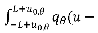
- Equation 1.14 (e.g., ⁇ ⁇ L L q ⁇ ⁇ ⁇ u e ⁇ i ⁇ t u du ) provides the relation between phase history data and range profile under scene rotation angle ⁇ .
- Equation 1.15 (e.g., k 3 ⁇ ⁇ L L q ⁇ u e i ⁇ t ku du ) provides the relation between phase history data and range profile scale factor k.
- Equation 1.16 (e.g., ⁇ ⁇ L + u 0 , ⁇ L + u 0 , ⁇ q ⁇ ( u ⁇ u 0, ⁇ ) e - i ⁇ ( t ) u du ) provides the relation between phase history data and range profile translation value (x o ,y o ).
- an algorithm e.g., illustrated as algorithm 400 in Fig. 4
- SAR range profile template of scene 102 includes a minimum number of non-zero values (e.g., SAR range profile template data of scene 102 is approximately sparse).
- Each SAR template includes phase history data and is pre-stored in memory 214 as SAR phase history template data 112'A-C, for example.
- SAR phase history template data r temp (5, u ) is converted to a SAR range profile template q temp (5, u ) using a ID-fast Fourier transform (e.g., 1D-FFT).
- SAR range profile template q temp (5, u ) is stored in memory 214.
- the range profile domain is used to efficiently estimate unknown rotation angle and translation value (x o ,y o ), where the rotation angle 5 and translation value (x o ,y o ) form a part of the estimated geometric transformation.
- the unknown rotation angle 5 and translation value (x o ,y o ) are solved for using equation 1.17 and algorithm 400 as discussed in Fig. 4 .
- the estimated geometric transformation e.g., rotation angle 5 and translation value (x o ,y o )
- at least one view e.g., at least one observation view 108A-C
- the estimated geometric transformation e.g., rotation angle 5 and translation value (x o ,y o )
- at least one view e.g., at least one observation view 108A-C
- the estimated geometric transformation e.g., rotation angle 5 and translation value (x o ,y o ) of at least one view (e.g., at least one observation view 108A-C) of scene 102 encoded in the received phase history data 112A-C with respect to a reference phase history template data 112'A-C of the same scene 102 is computed and stored in memory 214.
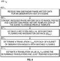
- Fig. 4 illustrates a flow diagram describing algorithm 400 for estimating geometric transformations of a scene encoded in the received phase history data with respect to a reference template in accordance with an embodiment of the disclosure.
- Algorithm 400 used for finding the rotation angle and translation between SAR phase history template data 112'A-C and received radar phase history data 112A-C, starts with block 403.
- phase history data r obs (5, u ) captured at an observation view 108 is received from a SAR sensor 220. Only limited phase history data of scene 102 is required to support estimating geometric transformations. These result in less memory and computational complexity required to execute algorithm 400.
- a limited subset of raw radar phase history data 112 of scene 102 is collected.
- a complete set of raw radar phase history data 112 of scene 102 e.g., a complete radar image of scene 102 are collected and a subset of rows are chosen from the complete set of received phase history data 112 to support execution of algorithm 400.
- a 1D fast Fourier Transform is applied to the observed phase history data r obs (5, u ) and a phase history template r temp (5, u ) that is retrieved from memory 214.
- the FFT of the phase history data generates respective range profile q obs (5, u ) and range profile template q temp (5, u ).
- a translation u 0, ⁇ value is fixed, and an optimal rotation angle 5 is determined with matched filtering and a Wasserstein distance ⁇ w p using equation 2.1.
- the rows of the range profile can be very sparse and consist of a few spikes that resemble probability distributions.
- the Wasserstein distance is a suitable measure for comparing probability distributions because it takes into account the distance between sparse spikes by taking the difference of the cumulative sparse distributions.
- a rotation angle 5 is fixed, and an optimal translation u 0, ⁇ is determined for each of a subset of observation angles 5 (e.g., observation views 5 1 through 5 3 , for example) with matched filtering.
- algorithm 400 provides for a flexible and efficient matching and registration numerical method for estimating geometric transformations such as rotation angle 5 and translation value (x ⁇ ,y ⁇ ) used in SAR-based navigation system 100. Comparing a range profile of the scene to a range profile template of the same scene provides for a computationally efficient method of estimating a geometric transformation of the scene encoded in the received phase history data with respect to a reference template.
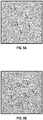
- Figs. 5A-D illustrate graphs of SAR phase history data and range profiles, as illustrative examples, in accordance with embodiments of the disclosure.
- Fig. 5A illustrates a two thousand by two thousand pixels simulation of an image of a template for a scene with five small objects 530-534, each providing features that can be matched and are sparsely distributed within the scene.
- Fig. 5A phase history template data was simulated with four hundred twenty four (424) frequencies and three hundred sixty (360) by one hundred seventeen (117) angles of observation.
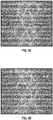
- Fig. 5C illustrates a respective range profile of Fig. 5A SAR phase history template data.
- Each of small objects 530-534 of Fig. 5A corresponds to a sinusoidal shape in Fig. 5C.
- Fig. 5D illustrates a respective range profile of Fig. 5B observed phase history data.
- Fig. 5D illustrates that each of the sinusoidal shapes have changed shape when small objects 530-534 have shifted as shown in Fig. 5B .
- Algorithm 400 was implemented with ten randomly chosen range profile row vectors to estimate the rotation angle 5 and ten randomly chosen range profile column vectors to estimate the translation value (x ⁇ ,y ⁇ ), representing an under-sampling by a factor of one hundred seventy five (175) times.
- the estimate using algorithm 400 for the rotation angle estimate was ninety degrees, identical to expected.
- algorithm 400 achieves near exact estimation of the unknown translation and rotation angle parameters without the need for image reconstruction and feature detection.
- Estimation of the unknown translation and rotation angle parameters is performed by under-sampling the observation SAR phase history data by a factor of one hundred seventy five (175).
- under-sampling requires less computational complexity and resources to perform algorithm 400 and makes possible SAR-based navigation on autonomous platforms with limited computational power and resources, such as aerial vehicle 101.
- various embodiments provided by the present disclosure can be implemented using hardware, software, or combinations of hardware and software. Also where applicable, the various hardware components and/or software components set forth herein can be combined into composite components comprising software, hardware, and/or both without departing from the present disclosure. Where applicable, the various hardware components and/or software components set forth herein can be separated into sub-components comprising software, hardware, or both without departing from the present disclosure. In addition, where applicable, it is contemplated that software components can be implemented as hardware components, and vice-versa.
- Software in accordance with the present disclosure can be stored on one or more computer readable media. It is also contemplated that software identified herein can be implemented using one or more general purpose or specific purpose computers and/or computer systems, networked and/or otherwise. Where applicable, the ordering of various steps described herein can be changed, combined into composite steps, and/or separated into sub-steps to provide features described herein.
Landscapes
- Engineering & Computer Science (AREA)
- Remote Sensing (AREA)
- Radar, Positioning & Navigation (AREA)
- Physics & Mathematics (AREA)
- Electromagnetism (AREA)
- Computer Networks & Wireless Communication (AREA)
- General Physics & Mathematics (AREA)
- Signal Processing (AREA)
- Radar Systems Or Details Thereof (AREA)
Abstract
Description
- One or more embodiments relate generally to Synthetic Aperture Radar (SAR) mapping and registration, and more particularly, for example, to techniques for range profile based SAR mapping and registration.
- In the field of synthetic aperture radar (SAR) based navigation systems, there is an ongoing effort to reduce computational complexity and resources required, particularly on autonomous platforms with limited computational power. In some global positioning system (GPS) denied environments, navigation guidance is provided by SAR imagery. Conventional SAR imagery navigation systems apply techniques developed in image processing for matching and registration of processed SAR images of a scene to expected ground landmarks of the same scene. Contemporary SAR based navigation methods require extensive processing and data resources for SAR image reconstruction and feature detection. Thus, there is a need for improved techniques for synthetic aperture (SAR) based navigation on platforms, such as for example for systems with limited computational power and resources.
- Systems and methods are disclosed herein in accordance with one or more embodiments that provide techniques for matching and registration of SAR radar phase history data, for example, to estimate geometric transformations of the data with respect to reference templates in order to provide navigation guidance. In one or more embodiments, SAR phase history data of a scene is converted to a range profile domain and compared to a range profile of a template of the same scene to provide for efficient SAR-based navigation.
- In one embodiment, a method includes receiving phase history data associated with observation views of a scene; converting the received phase history data associated with the observation views to a range profile of the scene; and comparing the range profile to a range profile template of the scene to estimate a geometric transformation of the scene encoded in the received phase history data with respect to a reference template.
- In another embodiment, a method includes retrieving phase history template data of a scene from a memory; converting the phase history template data to a range profile template of the scene; and storing the range profile template of the scene to the memory.
- In a further embodiment, a system includes a memory comprising a plurality of executable instructions; and a processor adapted to: receive phase history data associated with observation views of a scene; convert the received phase history data associated with the observation views to a range profile of the scene; and compare the range profile to a range profile template of the scene to estimate a geometric transformation of the scene encoded in the received phase history data with respect to a reference template.
- The invention is defined by the claims, which are incorporated into this section by reference. A more complete understanding of embodiments of the invention will be afforded to those skilled in the art, as well as a realization of additional advantages thereof, by a consideration of the following detailed description of one or more embodiments. Reference will be made to the appended sheets of drawings that will first be described briefly.
-
-
Fig. 1 illustrates a diagram of a spotlight-mode SAR-based navigation system in accordance with one or more embodiments of the disclosure. -
Fig. 2 illustrates a block diagram of a SAR radar system for navigation guidance in accordance with an embodiment of the disclosure. -
Fig. 3 illustrates a flow diagram describing a method for estimating geometric transformations of a scene encoded in the received phase history data with respect to a reference template in accordance with an embodiment of the disclosure. -
Fig. 4 illustrates a flow diagram describing an algorithm for estimating geometric transformations of a scene encoded in the received phase history data with respect to a reference template in accordance with an embodiment of the disclosure. -
Figs. 5A-D illustrate graphs of SAR phase history data and range profiles in accordance with embodiments of the disclosure. - Systems and methods are provided for matching and registration of synthetic aperture radar (SAR) phase history data of a scene with a pre-stored template of the same scene to furnish navigation guidance information, for example, in accordance with one or more embodiments. In a GPS denied environment, a drone, a fixed wing craft, a spacecraft, or other type of unmanned or manned vehicle rely on SAR-based imaging to provide for navigation.
- In one or more embodiments described herein, navigation techniques are described that reduce the computation, memory, and transmission bandwidth required of conventional SAR-based navigation systems. For example, conventional SAR image navigation techniques often match salient features in multiple SAR images that can be easily detected and matched. Constructing multiple SAR images to use for such navigation techniques requires extensive computation resources, memory, and transmission bandwidth.
- In an illustrated embodiment, the systems and methods described herein rely on raw received phase history data from multiple views of a scene. Received phase history data from one or more views of the scene is converted to the range profile domain. Phase history data of a SAR template (e.g., a reference template) of the same scene is similarly converted to the range profile domain. A rotation angle and a translation of the observed radar phase history data are estimated and the observed radar phase history data is matched to the template of the same scene using the estimated rotation angle and translation to facilitate SAR-based navigation.
- An algorithm is used to find the rotation angle and translation between a SAR phase history template and received radar phase history by converting both to the range profile domain. In some embodiments, the received radar phase history data is under-sampled, and the phase history template data is under-sampled to match by selecting one or more subsets of rows that correspond to observation views sampled in the received phase history data. A rotation angle is estimated by using the received radar under-sampled phase history data with matched filtering and Wasserstein distance computations. A translation value is estimated by first finding row shifts for each observation view (e.g., viewed at an observation angle relative to a flight path of an aerial vehicle) with matched filtering, and utilizing the row shifts and a system of linear equations with least squares equations to solve for the translation value.
-
Fig. 1 illustrates a diagram of a SAR-basednavigation system 100 in accordance with one or more embodiments of the disclosure. In one or more embodiments, SAR-basednavigation system 100 is implemented as a spotlight-mode SAR-based navigation system, however, other mode implementations are possible, as described herein. In some embodiments, SAR-basednavigation system 100 is mounted on a moving platform such as anaerial vehicle 101, for example, and used to receive radarphase history data 112A-C of ascene 102.Electromagnetic waves 103 are sequentially transmitted and thebackscattered waves 104 are collected by a SAR radar system fornavigation guidance 105. Consecutive time intervals of radar transmission and reception are used to receive radarphase history data 112A-C ofscene 102 atdifferent positions 109A-C along aflight path 107. The combination of receivedbackscattered waves 104 allows construction of a synthetic aperture that is longer than the physical aperture length. Processing the combination of raw radar data (e.g., radarphase history data 112A-C of scene 102) enables the construction of a synthetic aperture radar image 110 (e.g., a high resolution synthetic aperture radar image) of the capturedscene 102. However, this invention obviates the need for the construction of the synthetic aperture radar image in order to perform the navigation task, instead estimating the geometric transformation parameters directly from the range profiles of the received phase history data and phase history template data. - In some embodiments,
aerial vehicle 101, for example, is flown past or around scene 102 (e.g., a stationary ground location). In one or more embodiments,aerial vehicle 101 is any type of unmanned or manned aerial vehicle, such as a manned aircraft, an unmanned drone, or an orbiting spacecraft, for example.Scene 102 is illuminated withelectromagnetic waves 103 that are transmitted by a linear frequency modulated chirp signal, for example, from SAR radar system for navigation guidance 105 (e.g., SAR navigation guidance system 105) mounted toaerial vehicle 101.Backscattered waves 104 are received at SARnavigation guidance system 105 frommultiple observation views phase history data 112A-C, respectively. In some embodiments,phase history data 112A-C ofbackscattered waves 104 are received at one or more radar frequencies, ranging from one gigahertz to twelve gigahertz, for example. -
Fig. 2 illustrates a block diagram of a SAR radar system fornavigation guidance 105 in accordance with an embodiment of the disclosure. In some embodiments, SARnavigation guidance system 105 is used to capture and processphase history data 112A-C in accordance with various techniques described herein. In various embodiments, components of SARnavigation guidance system 105 are provided inaerial vehicle 101 implemented as a drone, for example. - In one embodiment, SAR
navigation guidance system 105 includes aprocessor 210, a synthetic aperture radar (SAR)sensor 220, and anantenna 230. In one or more embodiments, SARnavigation guidance system 105 is implemented as a synthetic radar device to capturephase history data 112A-C fromobservation views 108A-C, for example, of a scene 102 (e.g., a ground location). SARnavigation guidance system 105 represents any type of SAR radar device which transmits and receives electromagnetic radiation and provides representative data in the form of raw radarphase history data 112A-C. In some embodiments, SARnavigation guidance system 105 is implemented to transmit and receive radar energy pulses in one or more frequency ranges from approximately one gigahertz to sixteen gigahertz. However, in other embodiments, other frequencies are possible from frequencies less than one gigahertz to greater than sixteen gigahertz. In some embodiments, SARnavigation guidance system 105 is mounted to a platform of various types of unmanned flying vehicles, such as, for example, a drone or an orbiting spacecraft. In other embodiments, SARnavigation guidance system 105 is mounted to a platform of various types of manned flying vehicles. -
Processor 210 includes, for example, a microprocessor, a single-core processor, a multi-core processor, a microcontroller, an application-specific integrated circuit (ASIC), a logic device (e.g., a programmable logic device configured to perform processing operations), a digital signal processing (DSP) device, one or more memories for storing executable instructions (e.g., software, firmware, or other instructions), and/or any other appropriate combination of processing device and/or memory to execute instructions to perform any of the various operations described herein.Processor 210 is adapted to interface and communicate withmemory 214 andSAR sensor 220 via acommunication interface 212 to perform method and processing steps as described herein.Communication interface 212 includes wired or wireless communication buses within aerial vehicles described herein. - In various embodiments, it should be appreciated that processing operations and/or instructions are integrated in software and/or hardware as part of
processor 210, or code (e.g., software or configuration data) which is stored in amemory 214. Embodiments of processing operations and/or instructions disclosed herein are stored by a machinereadable medium 213 in a non-transitory manner (e.g., a memory, a hard drive, a compact disk, a digital video disk, or a flash memory) to be executed by a computer (e.g., logic or processor-based system) to perform various methods disclosed herein. In one or more embodiments, the machinereadable medium 213 is included as part ofprocessor 210. -
Memory 214 includes, in one embodiment, one or more memory devices (e.g., one or more memories) to store data and information. The one or more memory devices includes various types of memory including volatile and non-volatile memory devices, such as RAM (Random Access Memory), ROM (Read-Only Memory), EEPROM (Electrically-Erasable Read-Only Memory), flash memory, or other types of memory. In one embodiment,processor 210 is adapted to execute software stored inmemory 214 to perform various methods, processes, and operations in a manner as described herein. In various embodiments,memory 214 stores receivedphase history data 112A-C of a scene and/or phase history template data 112'A-C of the same scene. -
SAR sensor 220, in some embodiments, is used to transmit electromagnetic waves 103 (e.g., radar pulse energy) and receive backscattered waves 104 (e.g., receivedphase history data 112A-C) ofscene 102, for example.SAR sensor 220 includes, in one embodiment, a radar transmitter to produce radar pulses that are provided to anantenna 230 and radiated in space towardscene 102 byantenna 230 aselectromagnetic waves 103.SAR sensor 220 further includes a radar receiver to receivebackscattered waves 104 fromantenna 230. Backscattered waves 104 are received bySAR sensor 220 as receivedphase history data 112A-C at respective observation angles 108A-C ofscene 102.SAR sensor 220 communicates receivedphase history data 112A-C toprocessor 210 and/ormemory 214 viacommunication interface 212. -
Antenna 230, in some embodiments, is implemented to both transmitelectromagnetic waves 103 and receive backscattered waves 104. In some embodiments,antenna 230 is implemented as a parabolic antenna. In other embodiments,antenna 230 is implemented as a phased array antenna. However, other implementations ofantenna 230 are possible. - In one or more embodiments, SAR-based
navigation system 100 is implemented using an algorithm for estimating geometric transformations. However, other modes of SAR-basednavigation system 100 are possible, as discussed herein. Geometric transformations, such as rotation, translation, and scaling are mapped to the SAR phase history domain and the range profile domain. In this regard, the numerical method convertsphase history data 112A-C to a range profile domain for the multiple observation views 108A-C of scene 102 (e.g., observation angles) and SAR phase history template data 112'A-C of thesame scene 102 and solves for geometric transformations in the range profile domain. - A classical observation model is provided with the following description and equations. Let f(5,5) be the complex reflectivity profile of the target scene, which is centered at (0,0) with radius L. If the pulse used is a linear frequency modulated (FM) chirp signal provided by equation 1.1


- The filtered back-projection method is an efficient image formation method because it leverages the fast Fourier transform (FFT) by reformulating the observed signal in equation 1.3:

2 +y2 ≤L2 f(x,y)δ(u - x - y)dxdy is the projection profile along angle θ. The filtered back-projection method utilizes 1D- FFT and does not require interpolation of the data from the polar grid to the Cartesian grid, as required for the polar format algorithm, a fast method that utilizes 2D FFT. - The effects of geometric transformations on SAR phase history data are derived. In particular, the phase history transformations under scene rotation, scaling, and translation is derived below.
- The spotlight-mode SAR phase history formulation can be expressed as a Fourier transform of the range profile (projection profile along an angle). The range profile of the scene f(5,5) (complex-valued reflectivities) along angle 5 is the sum of reflectivities at a distance 5+5 given by equation 1.4:

- The phase history data (what the sensor receives) at observation angle (e.g., observation view) is given by equation 1.5:


- Rotation: If f(5,5) is rotated at an angle 5, the sensor receives at the observation angle 5 a rotation given by equation 1.6:

- Scaling: If f(5,5)is scaled by 5, the sensor receives at the observation angle 5 a scaling given by equation 1.7:

- To derive this, first let g(5,5) =5(5/5,5/5) be the scaled view of the scene. Substitute x̃=5/5 and ỹ=515, and the range profile at distance 5+5 along angle 5 is given by equation 1.8:

- Let ũ=5/5. The sensor receives at observation angle 5 a scaling given by equation 1.9:

- Translation: If f(5,5) is translated by (50,50), the sensor receives at observation angle 5 a translation given by equation 1.10:


- The sensor receives at observation angle 5 a translation given by equation 1.12:

- Combining the three geometric transformations (e.g., Rotation + Scaling + Translation), the sensor receives at observation angle 5 (e.g., observation view) a rotation, scaling, and translation given by equation 1.13:

- Range profiles can be efficiently reconstructed from the raw phase history data of equation 1.13. The first step of the filtered back-projection utilizes the 1D fast Fourier Transform (FFT) and recovers the range profiles, before reconstructing the image scene. To estimate the unknown geometric transformations, the relation between the phase history data and range profiles are expressed as the following:
Rotation by 5:


- The following is a SAR registration method operating in the range profile domain. Since rotation and translation can be expressed in the range profiles (scaling causes different spatial frequency: 5(5)5), range profiles can be efficiently computed via 1D-FFT, and range profiles are approximately sparse, we estimate the unknown rotation and translation in the range profile domain.
- Given SAR phase history template 5template(5,5) and phase history data 5observation(5, 5), the unknown rotation 5 and translation (50,50) is estimated by the following optimization formula given in equation 1.17:

- In this formulation, 5 is an unknown constant that needs to be estimated, and 50,5 = 50cos5 - 50sin5 is another unknown that depends on the observation angle 5, which in turn requires estimations of two constants, 50 and 50. An algorithm, as described further herein, is used to solve for the unknown rotation 5 and translation (50,y0).
-
Fig. 3 illustrates a flow diagram describing a method for estimating geometric transformations of a scene encoded in the received phase history data with respect to a reference template in accordance with an embodiment of the disclosure. The method described is an efficient method for matching and registration of synthetic aperture radar phase history data of a scene with phase history template data of the same scene. Significantly, SAR phase history data provides pixel information sufficient to enable SAR-based navigation without the need for computationally intensive SAR image reconstruction and feature detection. In this regard, both receivedphase history data 112A-C of the scene and phase history template data 112'A-C of the same scene are approximately sparse (e.g., include a minimum number of non-zero pixel values). Both received phase history data of the scene and template data of the same scene are mapped from the phase history domain to the range profile domain for computing estimates of geometric transformations such as rotation, translation, and scaling. - In
block 302, SAR-basednavigation system 100, operating in a spotlight-mode, for example, in this illustrative embodiment, receives backscatteredwaves 104 fromscene 102 at associated observation views 108A, 108B, and 108C to provide different projections ofscene 102. It is understood SAR-based navigation system can operate in one or more modes, such as, for example, strip map, scan, spotlight, or other modes applicable to SAR-based navigation. Backscattered waves 104 are processed bySAR sensor 220 and received byprocessor 210 asphase history data 112A-C ofscene 102 that include phase history data robs(5,u). - In
block 304, phase history data robs(5,u) for at least one of the observation views 108A-C ofscene 102 is received byprocessor 210. Receivedphase history data 112A-C is converted from the phase history domain to a range profile domain. For example, in spotlight-mode SAR, a reconstruction method is to convert phase history data robs(5,u) to a range profile qobs(5,u) using a ID-fast Fourier transform (e.g., 1D-FFT), followed by a Radon transform. The relation between phase history data robs(5,u) and range profile qobs(5,u) with respect to geometric transformations ofscene 102 is provided by three equations. Equation 1.14 (e.g.,

- In
block 306, an algorithm (e.g., illustrated asalgorithm 400 inFig. 4 ) is used to estimate a geometric transformation ofscene 102 using the range profile data ofblock 304 and a SAR range profile template of thesame scene 102. In some embodiments, SAR range profile template ofscene 102 includes a minimum number of non-zero values (e.g., SAR range profile template data ofscene 102 is approximately sparse). Each SAR template includes phase history data and is pre-stored inmemory 214 as SAR phase history template data 112'A-C, for example. SAR phase history template data rtemp(5,u) is converted to a SAR range profile template qtemp(5,u) using a ID-fast Fourier transform (e.g., 1D-FFT). In some embodiments, SAR range profile template qtemp(5,u) is stored inmemory 214. - The range profile domain is used to efficiently estimate unknown rotation angle and translation value (xo,yo), where the rotation angle 5 and translation value (xo,yo) form a part of the estimated geometric transformation. The unknown rotation angle 5 and translation value (xo,yo) are solved for using equation 1.17 and
algorithm 400 as discussed inFig. 4 . In this regard, the estimated geometric transformation (e.g., rotation angle 5 and translation value (xo,yo)) of at least one view (e.g., at least oneobservation view 108A-C) ofscene 102 encoded in the receivedphase history data 112A-C with respect to a reference phase history template data 112'A-C of thesame scene 102 is computed and stored inmemory 214. -
Fig. 4 illustrates a flowdiagram describing algorithm 400 for estimating geometric transformations of a scene encoded in the received phase history data with respect to a reference template in accordance with an embodiment of the disclosure.Algorithm 400, used for finding the rotation angle and translation between SAR phase history template data 112'A-C and received radarphase history data 112A-C, starts withblock 403. - In
block 403, phase history data robs(5,u) captured at an observation view 108 is received from aSAR sensor 220. Only limited phase history data ofscene 102 is required to support estimating geometric transformations. These result in less memory and computational complexity required to executealgorithm 400. In this regard, in some embodiments, a limited subset of raw radar phase history data 112 ofscene 102 is collected. In other embodiments, a complete set of raw radar phase history data 112 of scene 102 (e.g., a complete radar image of scene 102) are collected and a subset of rows are chosen from the complete set of received phase history data 112 to support execution ofalgorithm 400. - In
block 405, a 1D fast Fourier Transform (FFT) is applied to the observed phase history data robs(5,u) and a phase history template rtemp(5,u) that is retrieved frommemory 214. The FFT of the phase history data generates respective range profile qobs(5,u) and range profile template qtemp(5,u). - In blocks 407-411, equation 1.17 is used to solve for an unknown rotation angle 5 and an unknown translation value (xο,yο), where u 0,θ = x 0 cosθ - y 0 sinθ. In
block 407, a translation u 0,θ value is fixed, and an optimal rotation angle 5 is determined with matched filtering and a Wasserstein distance ∥·∥ wp using equation 2.1.
- The rows of the range profile can be very sparse and consist of a few spikes that resemble probability distributions. The Wasserstein distance is a suitable measure for comparing probability distributions because it takes into account the distance between sparse spikes by taking the difference of the cumulative sparse distributions.
- In
block 409, a rotation angle 5 is fixed, and an optimal translation u 0,θ is determined for each of a subset of observation angles 5 (e.g., observation views 51 through 53, for example) with matched filtering. Inblock 411, a translation value (xo,yo) is then determined using a system of linear equations with least squares as given in equation 2.2.
- In this regard,
algorithm 400 provides for a flexible and efficient matching and registration numerical method for estimating geometric transformations such as rotation angle 5 and translation value (xο,yο) used in SAR-basednavigation system 100. Comparing a range profile of the scene to a range profile template of the same scene provides for a computationally efficient method of estimating a geometric transformation of the scene encoded in the received phase history data with respect to a reference template. -
Figs. 5A-D illustrate graphs of SAR phase history data and range profiles, as illustrative examples, in accordance with embodiments of the disclosure.Fig. 5A illustrates a two thousand by two thousand pixels simulation of an image of a template for a scene with five small objects 530-534, each providing features that can be matched and are sparsely distributed within the scene.Fig. 5A phase history template data was simulated with four hundred twenty four (424) frequencies and three hundred sixty (360) by one hundred seventeen (117) angles of observation.Fig. 5B illustrates a simulated observed phase history data for a transformed scene including the same five small objects 530-534 with a rotation and translation. In the example,Fig. 5B was rotated by ninety degrees and translated by xo = one hundred pixels and yo = twenty pixels, representing actual geometric transformations. -
Fig. 5C illustrates a respective range profile ofFig. 5A SAR phase history template data. Each of small objects 530-534 ofFig. 5A corresponds to a sinusoidal shape inFig. 5C. Fig. 5D illustrates a respective range profile ofFig. 5B observed phase history data.Fig. 5D illustrates that each of the sinusoidal shapes have changed shape when small objects 530-534 have shifted as shown inFig. 5B .Algorithm 400 was implemented with ten randomly chosen range profile row vectors to estimate the rotation angle 5 and ten randomly chosen range profile column vectors to estimate the translation value (xο,yο), representing an under-sampling by a factor of one hundred seventy five (175) times. - The
estimate using algorithm 400 for the rotation angle estimate was ninety degrees, identical to expected. The solution for the translation value (xο,yο) was approximately xo = ninety nine and sixty eight one hundredths (99.68) pixels and yo = nineteen and sixty nine one hundredths (19.69) pixels, representing a small relative error of less than one pixel. As illustrated,algorithm 400 achieves near exact estimation of the unknown translation and rotation angle parameters without the need for image reconstruction and feature detection. Estimation of the unknown translation and rotation angle parameters is performed by under-sampling the observation SAR phase history data by a factor of one hundred seventy five (175). Advantageously, under-sampling requires less computational complexity and resources to performalgorithm 400 and makes possible SAR-based navigation on autonomous platforms with limited computational power and resources, such asaerial vehicle 101. - Where applicable, various embodiments provided by the present disclosure can be implemented using hardware, software, or combinations of hardware and software. Also where applicable, the various hardware components and/or software components set forth herein can be combined into composite components comprising software, hardware, and/or both without departing from the present disclosure. Where applicable, the various hardware components and/or software components set forth herein can be separated into sub-components comprising software, hardware, or both without departing from the present disclosure. In addition, where applicable, it is contemplated that software components can be implemented as hardware components, and vice-versa.
- Software in accordance with the present disclosure, such as program code and/or data, can be stored on one or more computer readable media. It is also contemplated that software identified herein can be implemented using one or more general purpose or specific purpose computers and/or computer systems, networked and/or otherwise. Where applicable, the ordering of various steps described herein can be changed, combined into composite steps, and/or separated into sub-steps to provide features described herein.
- Embodiments described above illustrate but do not limit the invention. It should also be understood that numerous modifications and variations are possible in accordance with the principles of the present invention. Accordingly, the invention is defined only by the following claims.
Claims (15)
- A method comprising:receiving phase history data associated with observation views of a scene;converting the received phase history data associated with observation views to a range profile of the scene; andcomparing the range profile to a range profile template of the scene to estimate a geometric transformation of the scene encoded in the received phase history data with respect to a reference template.
- The method of claim 1, further comprising:estimating a rotation angle of the range profile using matched filtering and a Wasserstein distance;wherein the rotation angle forms a part of the estimated geometric transformation.
- The method of claim 1 or 2, further comprising:receiving an observation angle corresponding to each of the observation views of the scene; andstoring the observation angles in a memory.
- The method of claim 3, further comprising:selecting a subset of the observation angles; andestimating a translation value of the range profile using the selected subset of observation angles, matched filtering, and linear equations with least squares;wherein the translation value forms a part of the estimated geometric transformation.
- The method of any of the preceding claims, wherein the receiving comprises receiving the phase history data associated with the observation views of the scene from a synthetic aperture radar sensor.
- A method comprising:retrieving phase history template data of a scene from a memory;converting the phase history template data to a range profile template of the scene; andstoring the range profile template to the memory.
- The method of claim 6, wherein the retrieving comprises retrieving a subset of phase history template data from a plurality of phase history template data of the scene.
- The method of claim 6 or 7, wherein the converting the phase history template data to the range profile template comprises using a fast Fourier transform algorithm.
- A system comprising:a memory comprising a plurality of executable instructions; anda processor adapted to:receive phase history data associated with observation views of a scene;convert the received phase history data associated with observation views to a range profile of the scene; andcompare the range profile to a range profile template of the scene to estimate a geometric transformation of the scene encoded in the received phase history data with respect to a reference template.
- The system of claim 9, wherein the processor is configured to estimate a rotation angle of the range profile using matched filtering and a Wasserstein distance, and wherein the rotation angle forms a part of the geometric transformation.
- The system of claim 9 or 10, wherein each of the observation views corresponds to an associated observation angle, and wherein the observation angles are stored in the memory.
- The system of claim 11, wherein the processor is configured to select a subset of the observation angles and estimate a translation value of the range profile of the scene using the selected subset of observation angles with matched filtering and linear equations with least squares, and wherein the translation value forms a part of the geometric transformation.
- The system of claim any of claims 9-12, further comprising an aerial vehicle comprising an antenna and a synthetic aperture radar sensor, wherein the antenna is preferably configured to transmit radar pulse energy toward the scene and receive backscattered radar pulse energy reflected from the scene.
- The system of claim 13, wherein the synthetic aperture radar sensor is configured to provide a plurality of radar pulses to the antenna and receive the backscattered radar pulse energy from the antenna to capture the phase history data of the scene.
- The system of any of claims 9-14, wherein the phase history data, the range profile, the range profile template and the geometric transformation are stored in the memory.
Applications Claiming Priority (1)
| Application Number | Priority Date | Filing Date | Title |
|---|---|---|---|
| US15/630,690 US11131767B2 (en) | 2017-06-22 | 2017-06-22 | Synthetic aperture radar mapping and registration systems and methods |
Publications (1)
| Publication Number | Publication Date |
|---|---|
| EP3422043A1 true EP3422043A1 (en) | 2019-01-02 |
Family
ID=62748871
Family Applications (1)
| Application Number | Title | Priority Date | Filing Date |
|---|---|---|---|
| EP18179168.2A Pending EP3422043A1 (en) | 2017-06-22 | 2018-06-21 | Synthetic aperture radar mapping and registration systems and methods |
Country Status (3)
| Country | Link |
|---|---|
| US (1) | US11131767B2 (en) |
| EP (1) | EP3422043A1 (en) |
| CN (1) | CN109116350B (en) |
Cited By (1)
| Publication number | Priority date | Publication date | Assignee | Title |
|---|---|---|---|---|
| US20220229173A1 (en) * | 2021-01-08 | 2022-07-21 | The Boeing Company | Complex recurrent neural network for synthetic aperture radar (sar) target recognition |
Families Citing this family (11)
| Publication number | Priority date | Publication date | Assignee | Title |
|---|---|---|---|---|
| US11169258B2 (en) * | 2019-05-09 | 2021-11-09 | The Boeing Company | Transport-based synthetic aperture radar navigation systems and methods |
| US11333753B2 (en) * | 2019-10-14 | 2022-05-17 | The Boeing Company | Stripmap synthetic aperture radar (SAR) system utilizing direct matching and registration in range profile space |
| CN110954899B (en) * | 2019-12-19 | 2021-12-28 | 北京无线电测量研究所 | Sea surface ship target imaging method and device under high sea condition |
| US11397260B2 (en) * | 2020-01-06 | 2022-07-26 | Mistubishi Electric Research Laboratories, Inc. | System and method for radar imaging for antennas with position ambiguities |
| US11255960B2 (en) * | 2020-01-24 | 2022-02-22 | The Boeing Company | Synthetic aperture radar (SAR) based convolutional navigation |
| CN111401168B (en) * | 2020-03-06 | 2023-11-17 | 上海神添实业有限公司 | A multi-layer radar feature extraction and selection method for UAVs |
| CN112255602B (en) * | 2020-10-20 | 2021-07-16 | 中国科学院空天信息创新研究院 | A Noise Equivalent Backscattering Coefficient Determination Method for FMCW-SAR System |
| CN112612036B (en) * | 2020-12-01 | 2023-05-05 | 珠海一微半导体股份有限公司 | A boundary marking method and mobile robot |
| US12259466B2 (en) | 2021-01-08 | 2025-03-25 | The Boeing Company | System for extraction of a region of interest (ROI) from a composite synthetic aperture radar (SAR) system phase history |
| CN114442091B (en) * | 2021-12-30 | 2025-02-14 | 南京航空航天大学 | Two-dimensional baseline estimation method for vertical track of spaceborne SAR based on least squares method |
| CN119716857B (en) * | 2024-12-25 | 2025-11-07 | 电子科技大学 | Rapid registration method for video SAR based on data bunching |
Citations (5)
| Publication number | Priority date | Publication date | Assignee | Title |
|---|---|---|---|---|
| US5424742A (en) * | 1992-12-31 | 1995-06-13 | Raytheon Company | Synthetic aperture radar guidance system and method of operating same |
| US5430445A (en) * | 1992-12-31 | 1995-07-04 | Raytheon Company | Synthetic aperture radar guidance system and method of operating same |
| US6362775B1 (en) * | 2000-04-25 | 2002-03-26 | Mcdonnell Douglas Corporation | Precision all-weather target location system |
| US20110222781A1 (en) * | 2010-03-15 | 2011-09-15 | U.S. Government As Represented By The Secretary Of The Army | Method and system for image registration and change detection |
| GB2504051A (en) * | 1995-01-11 | 2014-01-22 | Aerospatiale | Method and apparatus for matching a model and an image of the same scene |
Family Cites Families (25)
| Publication number | Priority date | Publication date | Assignee | Title |
|---|---|---|---|---|
| US5052045A (en) * | 1988-08-29 | 1991-09-24 | Raytheon Company | Confirmed boundary pattern matching |
| EP0719435A1 (en) * | 1994-07-14 | 1996-07-03 | Koninklijke Philips Electronics N.V. | Mass detection in digital x-ray images using multiple threshold levels to discriminate spots |
| US6664917B2 (en) * | 2002-01-17 | 2003-12-16 | The Boeing Company | Synthetic aperture, interferometric, down-looking, imaging, radar system |
| US6703835B2 (en) * | 2002-04-11 | 2004-03-09 | Ge Medical Systems Global Technology Co. Llc | System and method for unwrapping phase difference images |
| US7071866B2 (en) * | 2004-03-26 | 2006-07-04 | Northrop Grumman Corporation | 2-d range hopping spread spectrum encoder/decoder system for RF tags |
| US7106243B2 (en) * | 2004-11-23 | 2006-09-12 | Raytheon Company | Technique for enhanced quality high resolution 2D imaging of ground moving targets |
| US7245250B1 (en) * | 2005-08-16 | 2007-07-17 | Itt Manufacturing Enterprises, Inc. | Synthetic aperture radar image compression |
| WO2007133085A1 (en) * | 2006-05-15 | 2007-11-22 | Telefonaktiebolaget Lm Ericsson (Publ) | A method and system for automatic classification of objects |
| GB0616293D0 (en) * | 2006-08-16 | 2006-09-27 | Imp Innovations Ltd | Method of image processing |
| US8154435B2 (en) * | 2008-08-22 | 2012-04-10 | Microsoft Corporation | Stability monitoring using synthetic aperture radar |
| US20100067806A1 (en) * | 2008-09-12 | 2010-03-18 | Halberd Match Corp. | System and method for pleographic recognition, matching, and identification of images and objects |
| US8026841B2 (en) * | 2008-09-18 | 2011-09-27 | Bae Systems Controls Inc. | Range and azimuth resolution enhancement for real-beam radar |
| CN101551455B (en) * | 2009-05-13 | 2011-10-19 | 西安电子科技大学 | 3D terrain imaging system of interferometric synthetic aperture radar and elevation mapping method thereof |
| CN101975940B (en) * | 2010-09-27 | 2012-11-28 | 北京理工大学 | Segmentation combination-based adaptive constant false alarm rate target detection method for SAR image |
| EP2636198A1 (en) * | 2010-11-03 | 2013-09-11 | Yair Linn | Phase detector |
| US9194818B2 (en) * | 2012-04-20 | 2015-11-24 | ASTRODESIGN, Inc. | Distance measurement system and optical resolution improvement apparatus |
| US8994577B1 (en) * | 2012-07-05 | 2015-03-31 | Sandia Corporation | Synthetic aperture radar images with composite azimuth resolution |
| FR3005187B1 (en) * | 2013-04-24 | 2015-05-29 | Commissariat Energie Atomique | SAR IMAGE RECOVERY BY MUTUAL INFORMATION. |
| WO2015041295A1 (en) * | 2013-09-18 | 2015-03-26 | 国立大学法人東京大学 | Terrain category classification method, terrain category classification program, and terrain category classification device |
| JP6349937B2 (en) * | 2014-05-09 | 2018-07-04 | 日本電気株式会社 | Fluctuation detection apparatus, fluctuation detection method, and fluctuation detection program |
| CN104007439B (en) * | 2014-05-30 | 2017-02-08 | 中国科学院电子学研究所 | Interferential circular SAR elevation estimation processing method |
| CN104166141B (en) * | 2014-08-11 | 2017-05-24 | 中国电子科技集团公司第三十八研究所 | Method for designing multiple-input-multiple-output synthetic aperture radar system on basis of sub-band synthesis |
| US9952313B2 (en) * | 2014-09-19 | 2018-04-24 | The Boeing Company | Phase calibration of a stepped-chirp signal for a synthetic aperture radar |
| US20170016987A1 (en) * | 2015-07-17 | 2017-01-19 | Her Majesty The Queen In Right Of Canada, As Represented By The Minister Of National Defence | Processing synthetic aperture radar images for ship detection |
| CN105447867B (en) * | 2015-11-27 | 2018-04-10 | 西安电子科技大学 | Spatial target posture method of estimation based on ISAR images |
-
2017
- 2017-06-22 US US15/630,690 patent/US11131767B2/en active Active
-
2018
- 2018-06-21 EP EP18179168.2A patent/EP3422043A1/en active Pending
- 2018-06-22 CN CN201810650215.6A patent/CN109116350B/en active Active
Patent Citations (5)
| Publication number | Priority date | Publication date | Assignee | Title |
|---|---|---|---|---|
| US5424742A (en) * | 1992-12-31 | 1995-06-13 | Raytheon Company | Synthetic aperture radar guidance system and method of operating same |
| US5430445A (en) * | 1992-12-31 | 1995-07-04 | Raytheon Company | Synthetic aperture radar guidance system and method of operating same |
| GB2504051A (en) * | 1995-01-11 | 2014-01-22 | Aerospatiale | Method and apparatus for matching a model and an image of the same scene |
| US6362775B1 (en) * | 2000-04-25 | 2002-03-26 | Mcdonnell Douglas Corporation | Precision all-weather target location system |
| US20110222781A1 (en) * | 2010-03-15 | 2011-09-15 | U.S. Government As Represented By The Secretary Of The Army | Method and system for image registration and change detection |
Cited By (2)
| Publication number | Priority date | Publication date | Assignee | Title |
|---|---|---|---|---|
| US20220229173A1 (en) * | 2021-01-08 | 2022-07-21 | The Boeing Company | Complex recurrent neural network for synthetic aperture radar (sar) target recognition |
| US12216198B2 (en) * | 2021-01-08 | 2025-02-04 | The Boeing Company | Complex recurrent neural network for Synthetic Aperture Radar (SAR) target recognition |
Also Published As
| Publication number | Publication date |
|---|---|
| CN109116350B (en) | 2023-08-22 |
| US20180372862A1 (en) | 2018-12-27 |
| US11131767B2 (en) | 2021-09-28 |
| CN109116350A (en) | 2019-01-01 |
Similar Documents
| Publication | Publication Date | Title |
|---|---|---|
| EP3422043A1 (en) | Synthetic aperture radar mapping and registration systems and methods | |
| US9417323B2 (en) | SAR point cloud generation system | |
| US11333753B2 (en) | Stripmap synthetic aperture radar (SAR) system utilizing direct matching and registration in range profile space | |
| US10802122B1 (en) | Methods and systems for calibration of multiple lidar devices with non-overlapping fields of view | |
| EP2660623B1 (en) | Imaging method and device in SAB mobile bistatic SAR | |
| AU2014233495B2 (en) | Systems and methods for navigating autonomous underwater vehicles | |
| US6011625A (en) | Method for phase unwrapping in imaging systems | |
| EP2759847B1 (en) | Method and apparatus for determining equivalent velocity | |
| US20240286720A1 (en) | Automatic camera registration and calibration using marine sensors | |
| US11255960B2 (en) | Synthetic aperture radar (SAR) based convolutional navigation | |
| US11029403B2 (en) | Millimeter-wave airborne radar for 3-Dimensional imaging of moving and stationary targets | |
| EP3341752A1 (en) | Video-assisted inverse synthetic aperture radar (vaisar) | |
| EP3001217A1 (en) | Method and apparatus for object localization | |
| Nies et al. | Analysis and focusing of bistatic airborne SAR data | |
| Magnard et al. | Analysis of a maximum likelihood phase estimation method for airborne multibaseline SAR interferometry | |
| CN106662644B (en) | Method and apparatus for detecting velocity and distance of at least one object relative to a receiver receiving a signal | |
| KR102151362B1 (en) | Image decoding apparatus based on airborn using polar coordinates transformation and method of decoding image using the same | |
| JP4937791B2 (en) | Radar image processing device | |
| US11169258B2 (en) | Transport-based synthetic aperture radar navigation systems and methods | |
| EP3001214A1 (en) | Method and apparatus for object localization | |
| US20170322302A1 (en) | Synthetic aperture radar signal processing device and synthetic aperture radar signal processing program | |
| CN120428223A (en) | Method and system for ground-range geometric imaging grid division based on synthetic aperture radar backprojection | |
| JP7646094B2 (en) | System and method for generating a radar image of a scene - Patents.com | |
| Dong et al. | Research on Rotating SAR 3D Imaging Method Based on Bayesian Estimation | |
| EP4556954A1 (en) | A method for suppressing sidelobes and ghost targets in sar images and a system thereof |
Legal Events
| Date | Code | Title | Description |
|---|---|---|---|
| PUAI | Public reference made under article 153(3) epc to a published international application that has entered the european phase |
Free format text: ORIGINAL CODE: 0009012 |
|
| STAA | Information on the status of an ep patent application or granted ep patent |
Free format text: STATUS: REQUEST FOR EXAMINATION WAS MADE |
|
| 17P | Request for examination filed |
Effective date: 20180621 |
|
| AK | Designated contracting states |
Kind code of ref document: A1 Designated state(s): AL AT BE BG CH CY CZ DE DK EE ES FI FR GB GR HR HU IE IS IT LI LT LU LV MC MK MT NL NO PL PT RO RS SE SI SK SM TR |
|
| AX | Request for extension of the european patent |
Extension state: BA ME |
|
| STAA | Information on the status of an ep patent application or granted ep patent |
Free format text: STATUS: EXAMINATION IS IN PROGRESS |
|
| 17Q | First examination report despatched |
Effective date: 20210430 |
|
| RAP3 | Party data changed (applicant data changed or rights of an application transferred) |
Owner name: THE BOEING COMPANY |