EP3421816A1 - Centrifugal compressor - Google Patents
Centrifugal compressor Download PDFInfo
- Publication number
- EP3421816A1 EP3421816A1 EP17774087.5A EP17774087A EP3421816A1 EP 3421816 A1 EP3421816 A1 EP 3421816A1 EP 17774087 A EP17774087 A EP 17774087A EP 3421816 A1 EP3421816 A1 EP 3421816A1
- Authority
- EP
- European Patent Office
- Prior art keywords
- heat shield
- straightening vanes
- centrifugal compressor
- straightening
- flow path
- Prior art date
- Legal status (The legal status is an assumption and is not a legal conclusion. Google has not performed a legal analysis and makes no representation as to the accuracy of the status listed.)
- Granted
Links
Images




Classifications
-
- F—MECHANICAL ENGINEERING; LIGHTING; HEATING; WEAPONS; BLASTING
- F04—POSITIVE - DISPLACEMENT MACHINES FOR LIQUIDS; PUMPS FOR LIQUIDS OR ELASTIC FLUIDS
- F04D—NON-POSITIVE-DISPLACEMENT PUMPS
- F04D29/00—Details, component parts, or accessories
- F04D29/58—Cooling; Heating; Diminishing heat transfer
- F04D29/582—Cooling; Heating; Diminishing heat transfer specially adapted for elastic fluid pumps
- F04D29/5853—Cooling; Heating; Diminishing heat transfer specially adapted for elastic fluid pumps heat insulation or conduction
-
- F—MECHANICAL ENGINEERING; LIGHTING; HEATING; WEAPONS; BLASTING
- F04—POSITIVE - DISPLACEMENT MACHINES FOR LIQUIDS; PUMPS FOR LIQUIDS OR ELASTIC FLUIDS
- F04D—NON-POSITIVE-DISPLACEMENT PUMPS
- F04D17/00—Radial-flow pumps, e.g. centrifugal pumps; Helico-centrifugal pumps
- F04D17/08—Centrifugal pumps
- F04D17/10—Centrifugal pumps for compressing or evacuating
- F04D17/12—Multi-stage pumps
-
- F—MECHANICAL ENGINEERING; LIGHTING; HEATING; WEAPONS; BLASTING
- F04—POSITIVE - DISPLACEMENT MACHINES FOR LIQUIDS; PUMPS FOR LIQUIDS OR ELASTIC FLUIDS
- F04D—NON-POSITIVE-DISPLACEMENT PUMPS
- F04D17/00—Radial-flow pumps, e.g. centrifugal pumps; Helico-centrifugal pumps
- F04D17/08—Centrifugal pumps
- F04D17/10—Centrifugal pumps for compressing or evacuating
- F04D17/12—Multi-stage pumps
- F04D17/122—Multi-stage pumps the individual rotor discs being, one for each stage, on a common shaft and axially spaced, e.g. conventional centrifugal multi- stage compressors
-
- F—MECHANICAL ENGINEERING; LIGHTING; HEATING; WEAPONS; BLASTING
- F04—POSITIVE - DISPLACEMENT MACHINES FOR LIQUIDS; PUMPS FOR LIQUIDS OR ELASTIC FLUIDS
- F04D—NON-POSITIVE-DISPLACEMENT PUMPS
- F04D29/00—Details, component parts, or accessories
- F04D29/26—Rotors specially for elastic fluids
- F04D29/28—Rotors specially for elastic fluids for centrifugal or helico-centrifugal pumps for radial-flow or helico-centrifugal pumps
- F04D29/284—Rotors specially for elastic fluids for centrifugal or helico-centrifugal pumps for radial-flow or helico-centrifugal pumps for compressors
-
- F—MECHANICAL ENGINEERING; LIGHTING; HEATING; WEAPONS; BLASTING
- F04—POSITIVE - DISPLACEMENT MACHINES FOR LIQUIDS; PUMPS FOR LIQUIDS OR ELASTIC FLUIDS
- F04D—NON-POSITIVE-DISPLACEMENT PUMPS
- F04D29/00—Details, component parts, or accessories
- F04D29/26—Rotors specially for elastic fluids
- F04D29/28—Rotors specially for elastic fluids for centrifugal or helico-centrifugal pumps for radial-flow or helico-centrifugal pumps
- F04D29/30—Vanes
-
- F—MECHANICAL ENGINEERING; LIGHTING; HEATING; WEAPONS; BLASTING
- F04—POSITIVE - DISPLACEMENT MACHINES FOR LIQUIDS; PUMPS FOR LIQUIDS OR ELASTIC FLUIDS
- F04D—NON-POSITIVE-DISPLACEMENT PUMPS
- F04D29/00—Details, component parts, or accessories
- F04D29/40—Casings; Connections of working fluid
- F04D29/42—Casings; Connections of working fluid for radial or helico-centrifugal pumps
- F04D29/4206—Casings; Connections of working fluid for radial or helico-centrifugal pumps especially adapted for elastic fluid pumps
- F04D29/4213—Casings; Connections of working fluid for radial or helico-centrifugal pumps especially adapted for elastic fluid pumps suction ports
-
- F—MECHANICAL ENGINEERING; LIGHTING; HEATING; WEAPONS; BLASTING
- F04—POSITIVE - DISPLACEMENT MACHINES FOR LIQUIDS; PUMPS FOR LIQUIDS OR ELASTIC FLUIDS
- F04D—NON-POSITIVE-DISPLACEMENT PUMPS
- F04D29/00—Details, component parts, or accessories
- F04D29/40—Casings; Connections of working fluid
- F04D29/42—Casings; Connections of working fluid for radial or helico-centrifugal pumps
- F04D29/44—Fluid-guiding means, e.g. diffusers
- F04D29/441—Fluid-guiding means, e.g. diffusers especially adapted for elastic fluid pumps
-
- F—MECHANICAL ENGINEERING; LIGHTING; HEATING; WEAPONS; BLASTING
- F04—POSITIVE - DISPLACEMENT MACHINES FOR LIQUIDS; PUMPS FOR LIQUIDS OR ELASTIC FLUIDS
- F04D—NON-POSITIVE-DISPLACEMENT PUMPS
- F04D29/00—Details, component parts, or accessories
- F04D29/40—Casings; Connections of working fluid
- F04D29/42—Casings; Connections of working fluid for radial or helico-centrifugal pumps
- F04D29/44—Fluid-guiding means, e.g. diffusers
- F04D29/46—Fluid-guiding means, e.g. diffusers adjustable
-
- F—MECHANICAL ENGINEERING; LIGHTING; HEATING; WEAPONS; BLASTING
- F04—POSITIVE - DISPLACEMENT MACHINES FOR LIQUIDS; PUMPS FOR LIQUIDS OR ELASTIC FLUIDS
- F04D—NON-POSITIVE-DISPLACEMENT PUMPS
- F04D29/00—Details, component parts, or accessories
- F04D29/40—Casings; Connections of working fluid
- F04D29/42—Casings; Connections of working fluid for radial or helico-centrifugal pumps
- F04D29/44—Fluid-guiding means, e.g. diffusers
- F04D29/46—Fluid-guiding means, e.g. diffusers adjustable
- F04D29/462—Fluid-guiding means, e.g. diffusers adjustable especially adapted for elastic fluid pumps
-
- F—MECHANICAL ENGINEERING; LIGHTING; HEATING; WEAPONS; BLASTING
- F04—POSITIVE - DISPLACEMENT MACHINES FOR LIQUIDS; PUMPS FOR LIQUIDS OR ELASTIC FLUIDS
- F04D—NON-POSITIVE-DISPLACEMENT PUMPS
- F04D29/00—Details, component parts, or accessories
- F04D29/58—Cooling; Heating; Diminishing heat transfer
-
- F—MECHANICAL ENGINEERING; LIGHTING; HEATING; WEAPONS; BLASTING
- F04—POSITIVE - DISPLACEMENT MACHINES FOR LIQUIDS; PUMPS FOR LIQUIDS OR ELASTIC FLUIDS
- F04D—NON-POSITIVE-DISPLACEMENT PUMPS
- F04D29/00—Details, component parts, or accessories
- F04D29/58—Cooling; Heating; Diminishing heat transfer
- F04D29/582—Cooling; Heating; Diminishing heat transfer specially adapted for elastic fluid pumps
- F04D29/584—Cooling; Heating; Diminishing heat transfer specially adapted for elastic fluid pumps cooling or heating the machine
-
- F—MECHANICAL ENGINEERING; LIGHTING; HEATING; WEAPONS; BLASTING
- F04—POSITIVE - DISPLACEMENT MACHINES FOR LIQUIDS; PUMPS FOR LIQUIDS OR ELASTIC FLUIDS
- F04D—NON-POSITIVE-DISPLACEMENT PUMPS
- F04D29/00—Details, component parts, or accessories
- F04D29/60—Mounting; Assembling; Disassembling
- F04D29/62—Mounting; Assembling; Disassembling of radial or helico-centrifugal pumps
- F04D29/624—Mounting; Assembling; Disassembling of radial or helico-centrifugal pumps especially adapted for elastic fluid pumps
-
- F—MECHANICAL ENGINEERING; LIGHTING; HEATING; WEAPONS; BLASTING
- F04—POSITIVE - DISPLACEMENT MACHINES FOR LIQUIDS; PUMPS FOR LIQUIDS OR ELASTIC FLUIDS
- F04D—NON-POSITIVE-DISPLACEMENT PUMPS
- F04D29/00—Details, component parts, or accessories
- F04D29/40—Casings; Connections of working fluid
- F04D29/42—Casings; Connections of working fluid for radial or helico-centrifugal pumps
- F04D29/44—Fluid-guiding means, e.g. diffusers
- F04D29/441—Fluid-guiding means, e.g. diffusers especially adapted for elastic fluid pumps
- F04D29/444—Bladed diffusers
Definitions
- the present invention relates to a centrifugal compressor configured to compress a fluid using an impeller.
- Centrifugal compressors used in industrial processes and process plants radially pass a fluid such as air or gas through a rotating impeller, and compress the fluid using a centrifugal force generated in passing the fluid.
- the centrifugal compressor includes, as a basic configuration, a casing and a rotor housed in the casing.
- the rotor includes a shaft rotatably supported in the casing, and a plurality of impellers secured to an outer peripheral surface of the shaft.
- the centrifugal compressors can be divided into a single stage type compressor including a single impeller, and a multistage type compressor including a plurality of impellers arranged in series in a direction of a rotation axis, and the latter multistage type centrifugal compressor is often used.
- a known object to be compressed by the centrifugal compressor is boil off gas (BOG), for example, as described in Patent Literature 1.
- a boil off gas of a liquefied natural gas (LNG) is a fluid of extremely low temperature.
- LNG liquefied natural gas
- a vicinity of a gas suction flow path is exposed in extremely low temperature, while an outer peripheral surface of the compressor is exposed to atmospheric temperature, which causes a large temperature difference. Then, thermal stress due to contraction of components occurs the vicinity of the suction flow path.
- Patent Literature 1 proposes heating the vicinity of the suction flow path using oil as a heat medium.
- Patent Literature 1 JP 2013-513064 W
- a casing that forms a shell of the centrifugal compressor and internal components provided in the casing have different thermal responses based on a difference in heat capacity from each other.
- a difference in thermal deformation (or thermal expansion) needs to be considered between a period from start to steady operation and a period from the steady operation to stop, with respect to the centrifugal compressor.
- the present invention has an object to provide a centrifugal compressor capable of reducing thermal contraction in a vicinity of a gas suction flow path at the beginning of an operation using a small amount of heat medium, and also accommodating thermal deformation that occurs during processes in its operation.
- a centrifugal compressor of the present invention includes: a rotor including a shaft rotatably supported in a casing and an impeller secured to an outer periphery of the shaft; a diaphragm surrounding the impeller from an outer peripheral side; a suction side casing head disposed so as to be spaced apart from the diaphragm on side where a fluid is suctioned; a temperature adjusting mechanism that is provided in the suction side casing head and configured to adjust a temperature of environment by flow of a heat medium; a heat shield that is provided between the suction side casing head and the diaphragm and defines, together with the impeller, a suction flow path through which the fluid is introduced to the impeller; and a plurality of straightening vanes that are provided in the suction flow path and configured to straighten the fluid flowing through the suction flow path, wherein even if the straightening vanes are displaced in a direction away from the heat shield, an interference state between the straightening vanes and the heat
- the shield that defines the suction flow path is provided. Therefore, it is possible to reduce thermal contraction in the vicinity of the gas suction flow path at the beginning of an operation.
- a casing and internal components provided in the casing have different thermal responses based on a difference in heat capacity from each other.
- a space between a heat shield and straightening vanes tends to be large in a period between start and steady operation of the centrifugal type compressor and small in a period between the steady operation and stop of the centrifugal type compressor.
- the interference state between the straightening vanes and the heat shield can be maintained. This can prevent a gap from being created between the straightening vanes and the shield throughout processes of its operation from start to steady operation and further up to stop.
- the plurality of straightening vanes may be secured to the diaphragm.
- the heat shield may include an interference maintaining groove in which top end sides of the straightening vanes move in a reciprocating manner in the diaphragm.
- the top end sides of the straightening vanes can move in a reciprocating manner in the interference maintaining groove, that is, the interference state in which the straightening vanes are inserted into the interference maintaining groove can be maintained. This can prevent a gap from being created between the heat shield and the straightening vanes, thereby preventing a reduction in straightening effect of the straightening vanes due to creation of the gap.
- Such an interference maintaining mechanism is suitable for a case of using a heat shield that should not be loaded due to its low rigidity.
- the plurality of straightening vanes may be integrally formed with the diaphragm.
- the heat shield may include a plurality of interference maintaining grooves in which top end sides of the plurality of straightening vanes move in a reciprocating manner respectively.
- the interference maintaining grooves corresponding to the straightening vanes are provided respectively, it is possible to reduce a gap between the respective straightening vanes and the diaphragm, thereby preventing a reduction in the straightening effect of the straightening vanes due to the gap.
- the top end sides of the straightening vanes are inserted into the interference maintaining grooves without any substantial gap respectively, it is possible to prevent or minimize the reduction in the straightening effect of the straightening vanes.
- the plurality of straightening vanes may include a sealing body having an annular shape and removably secured to the diaphragm and circumferentially connecting top ends of the plurality of straightening vanes.
- Such an interference maintaining mechanism is characterized in that the heat shield includes an interference maintaining groove having an annular shape in which the sealing body moves in a reciprocating manner.
- the sealing body can move in a reciprocating manner in the interference maintaining groove having an annular shape, thereby allowing a state in which the straightening vanes are inserted into the interference maintaining groove to be maintained.
- This can prevent a gap from being created between the heat shield and the straightening vanes, thereby preventing a reduction in straightening effect of the straightening vane due to creation of the gap.
- the sealing body is inserted into the interference maintaining groove without any substantial gap, it is possible to prevent or minimize the reduction in straightening effect of the straightening vanes.
- the plurality of straightening vanes may be secured to the heat shield via a seal material that seals between the straightening vanes and the heat shield. Even if the straightening vanes are displaced in a direction away from the heat shield, the seal material provided between the straightening vanes and the heat shield can contract. Thereby, it is possible to prevent a gap from being substantially created and maintain an interference state.
- a heat insulating space is preferably provided between the suction side casing head and the heat shield. This can keep heat transfer low from a fluid as an object to be compressed to the suction side casing head.
- the heat shield has an annular shape including an outer diameter side and an inner diameter side in a plan view, the outer diameter side is secured to a first casing and the inner diameter side is a free end.
- the plurality of straightening vanes include concave surfaces and convex surfaces facing the concave surfaces, and the plurality of straightening vanes are arranged symmetrically with respect to the fluid flowing through the suction flow path, and the concave surfaces are arranged to face a flow direction of the fluid.
- the shield that defines the suction flow path is provided, thereby possible to reduce thermal contraction a vicinity of the gas suction flow path at the beginning of the operation. Further, according to the centrifugal compressor of the present invention, the interference between the straightening vanes and the shield can prevent a gap from being created between the straightening vanes and the shield throughout processes from start to steady operation and further up to stop.
- a multistage type centrifugal compressor including a plurality of impellers will be described as an example of a centrifugal compressor.
- the centrifugal compressor 1 of this embodiment includes a casing 2 that forms a shell of the centrifugal compressor 1, and a rotor 7 rotatably supported in the casing 2.
- the rotor 7 includes a shaft 8 extending along an axis C, and a plurality of impellers 9 secured to an outer peripheral surface of the shaft 8.
- the centrifugal compressor 1 is used to compress a boil off gas (fluid F) of an LNG of extremely low temperature, and includes an oil heater 60 to reduce a temperature difference between the inside and outside of a suction side casing head 4 particularly at the beginning of an operation.
- an extending direction of the axis C of the shaft 8 is referred to as an axis direction, and a direction perpendicular to the axis C is referred to as a radial direction.
- an upstream side U and a downstream side L are specified with reference to a flow direction of the fluid F as an object to be compressed.
- the upstream side U and the downstream side L are relative to each other.
- a diaphragm 3 surrounding the impellers 9 from an outer peripheral side, the suction side casing head 4 spaced apart from the diaphragm 3 on the most upstream side U in the axis direction, a discharge side casing head 5 spaced apart from the diaphragm 3 on the most downstream side L in the axis direction, and a heat shield 11 secured to the suction side casing head 4 are provided.
- the diaphragm 3 in this embodiment has a configuration in which a plurality of diaphragm pieces 6 are arranged in the axis direction as an example.
- the impellers 9 pump the fluid F flowing from the upstream side U toward the downstream side L radially outward using a centrifugal force generated by the impellers 9 rotating with the shaft 8.
- a fluid flow path 12 through which the fluid F is made to flow from the upstream side U toward the downstream side L is formed in the casing 2.
- the casing 2 has a cylindrical shape and the rotor 7 is coaxially placed.
- a first journal bearing 13 is provided as a bearing device that rotatably supports an end of the upstream side U of the shaft 8.
- a thrust bearing 15 that supports the end of the upstream side U of the shaft is provided.
- the first journal bearing 13 is secured in the suction side casing head 4, and the thrust bearing 15 is secured to an outside of the suction side casing head 4.
- a dry gas seal 16 is provided on a radially inner side of the suction side casing head 4.
- the dry gas seal 16 is provided on the downstream side L of the first journal bearing 13.
- the dry gas seal 16 is a seal device configured to jet F gas such as a dry gas to airtightly seal around the shaft 8.
- a seal fin 30 including a plurality of fins is provided on the downstream side L of the dry gas seal 16. Any seal device capable of sealing a gap between the suction side casing head 4 and the shaft 8 may be adopted, not limited to the dry gas seal 16.
- a labyrinth seal may be provided as the seal device between the suction side casing head 4 and the shaft 8.
- the oil heater 60 is provided and also the heat shield 11 is provided to prevent a large temperature difference at the beginning of the operation.
- a second journal bearing 14 that rotatably supports an end of the downstream side L of the shaft 8 is provided.
- the second journal bearing 14 is secured in the discharge side casing head 5.
- a suction flow path 18 through which the fluid F is introduced from outside is provided on an end of the upstream side U of the casing 2.
- the suction flow path 18 is formed between the heat shield 11 and the diaphragm 3.
- a discharge flow path 19 through which the fluid F is discharged to the outside is provided.
- the discharge flow path 19 is formed between a shield member 64 and the diaphragm 3 on a discharge side.
- an internal space 20 is provided so as to communicate with the suction flow path 18 and the discharge flow path 19 and repeat to radially contract and expand.
- the internal space 20 serves as a space housing the impellers 9, and also as the fluid flow path 12 except for the impellers 9. As such, the suction flow path 18 and the discharge flow path 19 communicate with each other via the impellers 9 and the fluid flow path 12.
- each impeller 9 includes a substantially disk-like hub 22 having a gradually increasing diameter toward the downstream side L, a plurality of blades 23 radially mounted to the hub 22 and circumferentially arranged, and a shroud 24 mounted to circumferentially cover the top end sides of the plurality of blades 23.
- the fluid flow path 12 in the casing 2 extends toward the downstream side L while radially meandering, and is formed to connect between adjacent impellers 9, 9.
- the fluid F is, while flowing through the fluid flow path 12, compressed in a stepwise every time the fluid F passes each stage of the impellers 9.
- the fluid flow path 12 mainly includes a suction passage 25, a compression passage 26, a diffuser passage 27, and a return passage 28.
- a discharge scroll 29 for discharging the fluid F is provided.
- the suction side casing head 4 includes the oil heater 60 as a temperature adjusting mechanism configured to heat the suction side casing head 4.
- the oil heater 60 is provided to adjust temperature of the inside and outside of the centrifugal compressor 1, particularly, reduce a temperature difference between the inside and outside of the centrifugal compressor 1 at the beginning of the operation of the centrifugal compressor 1.
- the oil heater 60 includes a pipe line 61 formed in the suction side casing head 4, and an oil heater body 62 connected to the pipe line 61, and a heat medium HM is passed through the pipe line 61 to the oil heater body 62.
- the pipe line 61 is connected to a supply source of the heat medium HM.
- the oil heater body 62 has an annular shape and is formed to surround the shaft 8.
- a heat medium flow path 63 through which the heat medium HM supplied through the pipe line 61 circulates.
- a lubricant to be supplied to the first journal bearing 13 and the second journal bearing 14 can be supplied as the heat medium HM to the oil heater 60.
- Changing a temperature of the heat medium HM makes it possible to change a temperature for heating the suction side casing head 4, or cool the suction side casing head 4 in some cases.
- the upstream side U of the suction flow path 18 is defined by the heat shield 11 secured to the suction side casing head 4, and the downstream side L of the suction flow path 18 is defined by an end surface 3A of the diaphragm 3.
- a heat insulating space 10 is formed between the heat shield 11 and the suction side casing head 4.
- a head end surface 4A of the suction side casing head 4 facing the downstream side L is a circumferentially extending annular surface.
- the head end surface 4A includes a first flat portion 31 located on a radially outer side and perpendicular to the axis C, a conical first slope portion 32 located on a radially inner side of the first flat portion 31 and having a decreasing diameter toward the downstream side L, a second flat portion 33 located on a radially inner side of the first slope portion 32 and perpendicular to the axis C, and a conical second slope portion 34 located on a radially inner side of the second flat portion 33 and having a decreasing diameter toward the downstream side L.
- the heat shield 11 is a plate-like member having an annular shape in a plan view, and includes an outer diameter side and an inner diameter side. As shown in FIG. 2 , the heat shield 11 includes a securing portion 40 located on the outer diameter side, a first disk portion 41 formed on one side of the securing portion 40 with respect to the axis direction, a first conical portion 42 connected to the inner diameter side of the first disk portion 41, a second disk portion 43 connected to a radially inner side of the first conical portion 42, and a second conical portion 44 connected to a radially inner side of the second disk portion 43.
- the heat shield 11 is secured to the first flat portion 31 of the suction side casing head 4 via the securing portion 40, and has a cantilever structure in which the heat shield 11 is secured to the first flat portion 31 only by the securing portion 40.
- an inner diameter end of the heat shield 11 is a free end FE
- a gap G is provided between the free end FE of the heat shield 11 and the outer peripheral surface of the shaft 8. Since the inner diameter side of the heat shield 11 is the free end FE, the heat shield 11 thermally expands and contracts in the radial direction without any constraint.
- Principal surfaces of the first disk portion 41 and the second disk portion 43 are perpendicular to the axis C respectively.
- the first conical portion 42 and the second conical portion 44 each have a conical shape having a decreasing diameter toward the downstream side L.
- the securing portion 40 is a circumferentially extending annular portion.
- the securing portion 40 has a plurality of through holes H extending therethrough in the axis direction at predetermined circumferential intervals.
- FIG. 2 shows a particular vertical section, and shows only one through hole H.
- the heat shield 11 is removably secured to the first flat portion 31 by fastening a bolt B inserted through the through hole H in a screw hole formed in the first flat portion 31.
- an annular space that serves as the heat insulating space 10 is formed between the head end surface 4A of the suction side casing head 4 and the heat shield 11.
- the heat insulating space 10 is filled without a gap, with a heat insulating material 49 that makes it hard to transfer heat of the heat shield 11 to the suction side casing head 4.
- the heat insulating space 10 is not necessarily filled with the heat insulating material 49.
- the centrifugal compressor 1 is formed so that the straightening vanes 3B protrude toward the upstream side U from the end surface 3A of the diaphragm 3 provided on the most upstream side U.
- the straightening vanes 3B straighten a flow of the fluid F sucked from the suction flow path 18 to make the fluid F flow toward the downstream side L.
- the plurality of straightening vanes 3B are provided at predetermined intervals circumferentially of the end surface 3A.
- the straightening vanes 3B may be integrally formed with the diaphragm 3, for example, by cutting, or may be fabricated separately from the diaphragm 3 and joined to be secured to the end surface 3A by appropriate means.
- the plurality of straightening vanes 3B are arranged symmetrically with respect to the fluid F flowing through the suction flow path 18.
- concave surfaces 71 are directed counterclockwise CCW
- convex surfaces 72 are directed clockwise CW.
- concave surfaces 71 are directed clockwise CW
- convex surfaces 72 are directed clockwise CCW.
- the concave surfaces 71 of the straightening vanes 3B face the flow of the fluid F.
- the heat shield 11 in this embodiment has interference maintaining grooves 45 in positions corresponding to the plurality of respective straightening vanes 3B.
- the plurality of interference maintaining grooves 45 are formed at predetermined intervals circumferentially of the second disk portion 43 so as to penetrate through front and rear surfaces of the second disk portion 43.
- An opening area of each interference maintaining groove 45 is determined so that the straightening vane 3B is inserted into the interference maintaining groove 45 without any substantial gap and preferably can slide with almost no load.
- the interference maintaining grooves 45 do not necessarily penetrate through the front and rear surfaces of the heat shield 11 as long as interference between the heat shield 11 and the straightening vanes 3B can be maintained.
- a top end of the straightening vane 3B is inserted into the interference maintaining groove 45.
- a relationship in which the top end of the straightening vane 3B is inserted into the interference maintaining groove 45 irrespective of an operation state of the centrifugal compressor 1 is always maintained.
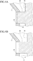
- a length of the straightening vane 3B and a depth of the interference maintaining groove 45 are set so that even if the straightening vane 3B is displaced most in a direction X away from the heat shield 11, the top end of the straightening vane 3B stays in the interference maintaining groove 45 in the heat shield 11 as shown in FIG. 4B .
- the straightening vane 3B moves in a reciprocating manner in the direction of the axis C in the interference maintaining groove 45, and an insertion depth of the straightening vane 3B into the interference maintaining groove 45 varies.
- the centrifugal compressor 1 according to the first embodiment has an advantageous effect as described below.
- the centrifugal compressor 1 can heat or cool the suction side casing head 4 by selecting the temperature of the heat medium HM supplied.
- the heat medium HM of high temperature can be supplied to reduce a temperature difference between the inside and outside of the centrifugal compressor 1, specifically, between the inside and outside of the suction side casing head 4.
- the centrifugal compressor 1 by the heat shield 11 provided between the suction side casing head 4 and the suction flow path 18, it is possible to suppress heat transfer between the suction side casing head 4 and the suction flow path 18.
- the centrifugal compressor 1 compresses the fluid F of extremely low temperature, it is possible to suppress a reduction in temperature of the suction side casing head 4 due to the fluid F, thereby reducing a flow rate of heat medium HM to be supplied to the oil heater 60.
- the centrifugal compressor 1 includes the heat insulating space 10 between the suction side casing head 4 and the heat shield 11, thereby further reducing heat transfer between the fluid F and the suction side casing head 4.
- the centrifugal compressor 1 includes the oil heater 60 and also includes the heat insulating space 10 and the heat shield 11, thereby reducing a temperature difference between the inside and outside of the centrifugal compressor 1 even when the centrifugal compressor 1 uses, as an object to be compressed, a fluid F having a large temperature difference from an ordinary temperature.
- This can prevent a defect in the seal device or the like lying a vicinity of the suction flow path 18 of the centrifugal compressor 1 due to thermal deformation that may occur at the beginning of the operation, using a smaller flow rate of heat medium HM.
- thermal deformation due to a temperature increase of the centrifugal compressor 1 occurs inevitably.
- the thermal deformation may cause a gap between the heat shield 11 and the top ends of the straightening vanes 3B, which makes it impossible to sufficiently obtain a straightening effect of the fluid F by the straightening vanes 3B.
- the top end of the straightening vane 3B is inserted into the interference maintaining groove 45 in the heat shield 11. Even if thermal deformation occurs and the straightening vane 3B is displaced most in the direction away from the heat shield 11, the top end of the straightening vane 3B stays in the interference maintaining groove 45 in the heat shield 11 as shown in FIG. 4B .
- the interference state in which the straightening vanes 3B are inserted into the heat shield 11 is maintained as long as the operation of the centrifugal compressor 1 is continued, the straightening effect of the fluid F by the straightening vanes 3B can be sufficiently obtained, thereby achieving a stable operation.
- straightening vanes 3B move in a reciprocating manner with respect to the heat shield 11, not only the above embodiment, but also for example, a variant of this embodiment shown in FIGS. 5 and 6 can be applied.
- FIG. 5B straightening vanes 3C are arranged on the end surface 3A similarly to the straightening vanes 3B described above.
- FIGS. 6A and 6B the straightening vanes 3C are removably mounted to the end surface 3A of the diaphragm 3.
- Each straightening vane 3C is fastened by a bolt B to the end surface 3A of the diaphragm 3.
- FIGS. 5B straightening vanes 3C are arranged on the end surface 3A similarly to the straightening vanes 3B described above.
- FIGS. 6A and 6B the straightening vanes 3C are removably mounted to the end surface 3A of the diaphragm 3.
- Each straightening vane 3C is fastened by a bolt B to the end surface 3A of
- a sealing body 3D is mounted to a tip of the straightening vane 3C.
- the sealing body 3D is a ring-like member, and as shown in FIG. 6B , the seal 3D is provided to cover the top ends of the plurality of straightening vanes 3C circumferentially arranged.
- a width W1 of the sealing body 3D is larger than a width W2 of the straightening vane 3C here, but the width W1 may be equal to the width W2.
- an interference maintaining groove 46 provided in the heat shield 11 is continuously formed into a circumferentially annular shape.
- a width W3 of the interference maintaining groove 46 is set so that the sealing body 3D is inserted into the interference maintaining groove 46 without any substantial gap.
- the respective straightening vanes 3C are inserted into the interference maintaining groove 46.
- the sealing body 3D located on the top end side of the straightening vanes 3C is inserted into the interference maintaining groove 46 together with the straightening vane 3C movably in a reciprocating manner.
- the top end side of the straightening vanes 3C is inserted into the interference maintaining groove 46 in the heat shield 11 together with the sealing body 3D. Even if thermal deformation occurs and the straightening vanes 3B are displaced most in the direction X away from the heat shield 11, the top ends of the straightening vanes 3C stay in the interference maintaining groove 46 in the heat shield 11 as shown in FIG. 6B . Thus, since the interference state in which the straightening vanes 3C and the sealing body 3D are inserted into the heat shield 11 is maintained as long as the operation of the centrifugal compressor 1 is continued, the straightening effect of the fluid F by the straightening vanes 3C can be sufficiently obtained. The sealing body 3D prevents the fluid F from entering the interference maintaining groove 46.
- the second embodiment also proposes a structure in which even if thermal deformation occurs and straightening vanes 3E are displaced in the direction X away from the heat shield 11, an interference state in which top ends of the straightening vanes 3E and the heat shield 11 are in contact is maintained.
- the straightening vanes 3E are removably secured on the side of the heat shield 11.
- the second embodiment is suitably applied to the heat shield 11 having high rigidity.
- the straightening vane 3E is mounted to the second disk portion 43 of the heat shield 11.
- the straightening vane 3E has a through hole H through which a bolt B extends.
- the through hole H has a small diameter portion through which the bolt B is inserted, and a large diameter portion that holds a nut N engaging the bolt B.
- the nut N is housed in the large diameter portion of the through hole H, and a top end of the bolt B extending through the straightening vane 3E is fastened by the nut N, thereby securing the straightening vane 3E to the heat shield 11.
- the end surface 3A of the diaphragm 3 has a bore 3F into which a head of the bolt B is inserted.
- a seal material 53 is provided on an uneven portion between the small diameter portion and the large diameter portion of the through hole H, and a seal material 54 is also provided between the heat shield 11 and the straightening vane 3E.
- the seal materials 53, 54 are made of rubber, resin, or the like, and the seal material 54 is provided along a peripheral edge of the straightening vane 3E.
- the straightening vane 3E can be displaced in the axis direction Y. If the seal material 53 in contact with the nut N is elastically deformed by a load applied in the axis direction Y of the bolt B, the bolt B together with the nut N can be displaced in the axis direction. Specifically, when the straightening vane 3E is forced in the axis direction Y of the bolt B, the straightening vane 3E is displaced together with the bolt B and the nut N in the axis direction Y.
- a seal material 55 may be provided around the head BH.
- the seal material 55 may be also provided on the top end surface of the head BH.
- the heat shield 11 having high rigidity is used.
- a configuration can be applied in which while the straightening vane 3E is secured by the bolt B, the seal material 53 is provided between the heat shield 11 and the bolt B and the seal material 54 is provided between the heat shield 11 and the straightening vane 3E. Then, by applying this configuration, the heat shield 11 and the straightening vane 3E are integrally displaced in the axis direction Y.
- the configurations of the oil heater 60 and the heat shield 11 are mere examples of the present invention, and any configurations of the oil heater 60 and the heat shield 11 may be adopted as long as an effect of reducing a temperature difference between the inside and outside of the centrifugal compressor can be obtained.
- any configuration for maintaining the interference state between the straightening vane and the heat shield may be adopted as long as the straightening effect of the straightening vanes can be ensured.
- the straightening vanes 3B may be provided on the side of the heat shield 11, and the interference maintaining grooves 45 may be provided on the side of the end surface 3A of the diaphragm 3.
Landscapes
- Engineering & Computer Science (AREA)
- Mechanical Engineering (AREA)
- General Engineering & Computer Science (AREA)
- Physics & Mathematics (AREA)
- Thermal Sciences (AREA)
- Structures Of Non-Positive Displacement Pumps (AREA)
Abstract

Description
- The present invention relates to a centrifugal compressor configured to compress a fluid using an impeller.
- Centrifugal compressors used in industrial processes and process plants radially pass a fluid such as air or gas through a rotating impeller, and compress the fluid using a centrifugal force generated in passing the fluid. The centrifugal compressor includes, as a basic configuration, a casing and a rotor housed in the casing. The rotor includes a shaft rotatably supported in the casing, and a plurality of impellers secured to an outer peripheral surface of the shaft.
- The centrifugal compressors can be divided into a single stage type compressor including a single impeller, and a multistage type compressor including a plurality of impellers arranged in series in a direction of a rotation axis, and the latter multistage type centrifugal compressor is often used.
- A known object to be compressed by the centrifugal compressor is boil off gas (BOG), for example, as described in Patent Literature 1. For example, a boil off gas of a liquefied natural gas (LNG) is a fluid of extremely low temperature. In this centrifugal compressor, particularly at the beginning of an operation, a vicinity of a gas suction flow path is exposed in extremely low temperature, while an outer peripheral surface of the compressor is exposed to atmospheric temperature, which causes a large temperature difference. Then, thermal stress due to contraction of components occurs the vicinity of the suction flow path. In order to reduce the temperature difference between the inside and outside of the centrifugal compressor, Patent Literature 1 proposes heating the vicinity of the suction flow path using oil as a heat medium.
- Patent Literature 1:
JP 2013-513064 W - However, reducing the temperature difference between the inside and outside of the centrifugal compressor only by heating with oil requires a large amount of oil, and cost increase caused by ancillary facilities and devices for that purpose becomes unignorable.
- On the other hand, a casing that forms a shell of the centrifugal compressor and internal components provided in the casing have different thermal responses based on a difference in heat capacity from each other. Thus, a difference in thermal deformation (or thermal expansion) needs to be considered between a period from start to steady operation and a period from the steady operation to stop, with respect to the centrifugal compressor.
- From the above, the present invention has an object to provide a centrifugal compressor capable of reducing thermal contraction in a vicinity of a gas suction flow path at the beginning of an operation using a small amount of heat medium, and also accommodating thermal deformation that occurs during processes in its operation.
- A centrifugal compressor of the present invention includes: a rotor including a shaft rotatably supported in a casing and an impeller secured to an outer periphery of the shaft; a diaphragm surrounding the impeller from an outer peripheral side; a suction side casing head disposed so as to be spaced apart from the diaphragm on side where a fluid is suctioned; a temperature adjusting mechanism that is provided in the suction side casing head and configured to adjust a temperature of environment by flow of a heat medium; a heat shield that is provided between the suction side casing head and the diaphragm and defines, together with the impeller, a suction flow path through which the fluid is introduced to the impeller; and a plurality of straightening vanes that are provided in the suction flow path and configured to straighten the fluid flowing through the suction flow path, wherein even if the straightening vanes are displaced in a direction away from the heat shield, an interference state between the straightening vanes and the heat shield is maintained.
- In the centrifugal compressor of the present invention, the shield that defines the suction flow path is provided. Thereby, it is possible to reduce thermal contraction in the vicinity of the gas suction flow path at the beginning of an operation.
- In a centrifugal type compressor, a casing and internal components provided in the casing have different thermal responses based on a difference in heat capacity from each other. Thus, a space between a heat shield and straightening vanes tends to be large in a period between start and steady operation of the centrifugal type compressor and small in a period between the steady operation and stop of the centrifugal type compressor. However, in the centrifugal compressor of the present invention, even if the straightening vanes are displaced in the direction away from the heat shield, the interference state between the straightening vanes and the heat shield can be maintained. This can prevent a gap from being created between the straightening vanes and the shield throughout processes of its operation from start to steady operation and further up to stop.
- In the present invention, the plurality of straightening vanes may be secured to the diaphragm. In this case, the heat shield may include an interference maintaining groove in which top end sides of the straightening vanes move in a reciprocating manner in the diaphragm.
- Thus, the top end sides of the straightening vanes can move in a reciprocating manner in the interference maintaining groove, that is, the interference state in which the straightening vanes are inserted into the interference maintaining groove can be maintained. This can prevent a gap from being created between the heat shield and the straightening vanes, thereby preventing a reduction in straightening effect of the straightening vanes due to creation of the gap.
- Such an interference maintaining mechanism is suitable for a case of using a heat shield that should not be loaded due to its low rigidity.
- In the present invention, the plurality of straightening vanes may be integrally formed with the diaphragm. In this case, the heat shield may include a plurality of interference maintaining grooves in which top end sides of the plurality of straightening vanes move in a reciprocating manner respectively.
- As such, when the interference maintaining grooves corresponding to the straightening vanes are provided respectively, it is possible to reduce a gap between the respective straightening vanes and the diaphragm, thereby preventing a reduction in the straightening effect of the straightening vanes due to the gap. In particular, when the top end sides of the straightening vanes are inserted into the interference maintaining grooves without any substantial gap respectively, it is possible to prevent or minimize the reduction in the straightening effect of the straightening vanes.
- As another means for using an interference maintaining groove, the plurality of straightening vanes may include a sealing body having an annular shape and removably secured to the diaphragm and circumferentially connecting top ends of the plurality of straightening vanes. Such an interference maintaining mechanism is characterized in that the heat shield includes an interference maintaining groove having an annular shape in which the sealing body moves in a reciprocating manner.
- In this interference maintaining mechanism, the sealing body can move in a reciprocating manner in the interference maintaining groove having an annular shape, thereby allowing a state in which the straightening vanes are inserted into the interference maintaining groove to be maintained. This can prevent a gap from being created between the heat shield and the straightening vanes, thereby preventing a reduction in straightening effect of the straightening vane due to creation of the gap. Also in this case, when the sealing body is inserted into the interference maintaining groove without any substantial gap, it is possible to prevent or minimize the reduction in straightening effect of the straightening vanes.
- As an interference maintaining mechanism of the present invention, the plurality of straightening vanes may be secured to the heat shield via a seal material that seals between the straightening vanes and the heat shield. Even if the straightening vanes are displaced in a direction away from the heat shield, the seal material provided between the straightening vanes and the heat shield can contract. Thereby, it is possible to prevent a gap from being substantially created and maintain an interference state.
- In the present invention, a heat insulating space is preferably provided between the suction side casing head and the heat shield. This can keep heat transfer low from a fluid as an object to be compressed to the suction side casing head.
- In the present invention, it is preferable that when the heat shield has an annular shape including an outer diameter side and an inner diameter side in a plan view, the outer diameter side is secured to a first casing and the inner diameter side is a free end.
- In the present invention, it is preferable that the plurality of straightening vanes include concave surfaces and convex surfaces facing the concave surfaces, and the plurality of straightening vanes are arranged symmetrically with respect to the fluid flowing through the suction flow path, and the concave surfaces are arranged to face a flow direction of the fluid.
- According to the centrifugal compressor of the present invention, the shield that defines the suction flow path is provided, thereby possible to reduce thermal contraction a vicinity of the gas suction flow path at the beginning of the operation. Further, according to the centrifugal compressor of the present invention, the interference between the straightening vanes and the shield can prevent a gap from being created between the straightening vanes and the shield throughout processes from start to steady operation and further up to stop.
-
-
FIG. 1 is a sectional view of a schematic configuration of a centrifugal compressor according to a first embodiment of the present invention. -
FIG. 2 is a sectional view of a vicinity of suction flow path of the centrifugal compressor inFIG. 1 . -
FIG. 3A shows a shield of the centrifugal compressor inFIG. 1 from a downstream side, andFIG. 3B shows straightening vanes formed on an end surface of a diaphragm of the centrifugal compressor inFIG. 1 from an upstream side. -
FIG. 4A shows interference between the shield and the straightening vane of the centrifugal compressor inFIG. 1 and shows deformation at the moment of start and deep interference between the shield and the straightening vane, andFIG. 4B shows the interference between the shield and the straightening vane of the centrifugal compressor inFIG.1 , and shows deformation at the moment of stop and shallow interference between the shield and the straightening vane. -
FIG. 5A shows a variant of the first embodiment and shows a shield viewed from a downstream side, andFIG. 5B shows the variant of the first embodiment and shows straightening vanes secured to anend surface 3A of a diaphragm viewed from an upstream side. -
FIG. 6A shows the variant of the first embodiment and shows a configuration thereof, andFIG. 6B shows the variant of the first embodiment and shows interference between the shield and the straightening vane. -
FIG. 7A shows an example of interference between the shield and a straightening vane according to a second embodiment and shows a configuration thereof, andFIG. 7B shows the example of interference between the shield and the straightening vane according to the second embodiment and shows the interference between the shield and the straightening vane. - Now, with reference to the accompanying drawings, embodiments of the present invention will be described.
- In this embodiment, a multistage type centrifugal compressor including a plurality of impellers will be described as an example of a centrifugal compressor.
- As shown in
FIG. 1 , the centrifugal compressor 1 of this embodiment includes acasing 2 that forms a shell of the centrifugal compressor 1, and a rotor 7 rotatably supported in thecasing 2. The rotor 7 includes a shaft 8 extending along an axis C, and a plurality ofimpellers 9 secured to an outer peripheral surface of the shaft 8. The centrifugal compressor 1 is used to compress a boil off gas (fluid F) of an LNG of extremely low temperature, and includes anoil heater 60 to reduce a temperature difference between the inside and outside of a suctionside casing head 4 particularly at the beginning of an operation. - In the centrifugal compressor 1, an extending direction of the axis C of the shaft 8 is referred to as an axis direction, and a direction perpendicular to the axis C is referred to as a radial direction. In the centrifugal compressor 1, as shown in
FIG. 1 , an upstream side U and a downstream side L are specified with reference to a flow direction of the fluid F as an object to be compressed. The upstream side U and the downstream side L are relative to each other. - As shown in
FIG. 1 , in thecasing 2, adiaphragm 3 surrounding theimpellers 9 from an outer peripheral side, the suctionside casing head 4 spaced apart from thediaphragm 3 on the most upstream side U in the axis direction, a discharge side casing head 5 spaced apart from thediaphragm 3 on the most downstream side L in the axis direction, and aheat shield 11 secured to the suctionside casing head 4 are provided. - The
diaphragm 3 in this embodiment has a configuration in which a plurality ofdiaphragm pieces 6 are arranged in the axis direction as an example. - The
impellers 9 pump the fluid F flowing from the upstream side U toward the downstream side L radially outward using a centrifugal force generated by theimpellers 9 rotating with the shaft 8. For that purpose, afluid flow path 12 through which the fluid F is made to flow from the upstream side U toward the downstream side L is formed in thecasing 2. - As shown in
FIG. 1 , thecasing 2 has a cylindrical shape and the rotor 7 is coaxially placed. In the suctionside casing head 4, a first journal bearing 13 is provided as a bearing device that rotatably supports an end of the upstream side U of the shaft 8. Further, on the upstream side U of the first journal bearing 13, athrust bearing 15 that supports the end of the upstream side U of the shaft is provided. The first journal bearing 13 is secured in the suctionside casing head 4, and thethrust bearing 15 is secured to an outside of the suctionside casing head 4. - As shown in
FIG. 1 , adry gas seal 16 is provided on a radially inner side of the suctionside casing head 4. Thedry gas seal 16 is provided on the downstream side L of the first journal bearing 13. Thedry gas seal 16 is a seal device configured to jet F gas such as a dry gas to airtightly seal around the shaft 8. In addition, aseal fin 30 including a plurality of fins is provided on the downstream side L of thedry gas seal 16. Any seal device capable of sealing a gap between the suctionside casing head 4 and the shaft 8 may be adopted, not limited to thedry gas seal 16. For example, a labyrinth seal may be provided as the seal device between the suctionside casing head 4 and the shaft 8. - If a large temperature difference suddenly occurs at the beginning of the operation to cause thermal contraction of the suction
side casing head 4, a sealed state by the seal device may deteriorate. Then, in this embodiment, theoil heater 60 is provided and also theheat shield 11 is provided to prevent a large temperature difference at the beginning of the operation. - On a radially inner side of the discharge side casing head 5, a second journal bearing 14 that rotatably supports an end of the downstream side L of the shaft 8 is provided. The second journal bearing 14 is secured in the discharge side casing head 5.
- As shown in
FIG. 1 , on an end of the upstream side U of thecasing 2, asuction flow path 18 through which the fluid F is introduced from outside is provided. Thesuction flow path 18 is formed between theheat shield 11 and thediaphragm 3. - On an end of the downstream side L of the
casing 2, adischarge flow path 19 through which the fluid F is discharged to the outside is provided. Thedischarge flow path 19 is formed between ashield member 64 and thediaphragm 3 on a discharge side. - In the
casing 2, aninternal space 20 is provided so as to communicate with thesuction flow path 18 and thedischarge flow path 19 and repeat to radially contract and expand. Theinternal space 20 serves as a space housing theimpellers 9, and also as thefluid flow path 12 except for theimpellers 9. As such, thesuction flow path 18 and thedischarge flow path 19 communicate with each other via theimpellers 9 and thefluid flow path 12. - As shown in
FIG. 1 , multiple stages ofimpellers 9 are arranged at intervals in the axis direction. Although six stages ofimpellers 9 are provided here as an example, the present invention may be applied to a centrifugal compressor including at least a single stage ofimpeller 9. As shown inFIG. 2 , eachimpeller 9 includes a substantially disk-like hub 22 having a gradually increasing diameter toward the downstream side L, a plurality ofblades 23 radially mounted to thehub 22 and circumferentially arranged, and ashroud 24 mounted to circumferentially cover the top end sides of the plurality ofblades 23. - As shown in
FIG. 1 , thefluid flow path 12 in thecasing 2, extends toward the downstream side L while radially meandering, and is formed to connect betweenadjacent impellers fluid flow path 12, compressed in a stepwise every time the fluid F passes each stage of theimpellers 9. As shown inFIG. 2 , thefluid flow path 12 mainly includes asuction passage 25, a compression passage 26, adiffuser passage 27, and areturn passage 28. - As shown in
FIG. 1 , in thecasing 2, adischarge scroll 29 for discharging the fluid F is provided. - Next, as shown in
FIGS. 1 and2 , the suctionside casing head 4 includes theoil heater 60 as a temperature adjusting mechanism configured to heat the suctionside casing head 4. Theoil heater 60 is provided to adjust temperature of the inside and outside of the centrifugal compressor 1, particularly, reduce a temperature difference between the inside and outside of the centrifugal compressor 1 at the beginning of the operation of the centrifugal compressor 1. Theoil heater 60 includes apipe line 61 formed in the suctionside casing head 4, and anoil heater body 62 connected to thepipe line 61, and a heat medium HM is passed through thepipe line 61 to theoil heater body 62. - The
pipe line 61 is connected to a supply source of the heat medium HM. Theoil heater body 62 has an annular shape and is formed to surround the shaft 8. In theoil heater body 62,a heatmedium flow path 63 through which the heat medium HM supplied through thepipe line 61 circulates. For example, a lubricant to be supplied to the first journal bearing 13 and the second journal bearing 14 can be supplied as the heat medium HM to theoil heater 60. Changing a temperature of the heat medium HM makes it possible to change a temperature for heating the suctionside casing head 4, or cool the suctionside casing head 4 in some cases. - Next, with reference to
FIG. 2 , a detailed structure of thesuction flow path 18 in the centrifugal compressor 1 of this embodiment will be described. - As shown in
FIG. 2 , the upstream side U of thesuction flow path 18 is defined by theheat shield 11 secured to the suctionside casing head 4, and the downstream side L of thesuction flow path 18 is defined by anend surface 3A of thediaphragm 3. Aheat insulating space 10 is formed between theheat shield 11 and the suctionside casing head 4. - A
head end surface 4A of the suctionside casing head 4 facing the downstream side L is a circumferentially extending annular surface. Thehead end surface 4A includes a firstflat portion 31 located on a radially outer side and perpendicular to the axis C, a conicalfirst slope portion 32 located on a radially inner side of the firstflat portion 31 and having a decreasing diameter toward the downstream side L, a secondflat portion 33 located on a radially inner side of thefirst slope portion 32 and perpendicular to the axis C, and a conicalsecond slope portion 34 located on a radially inner side of the secondflat portion 33 and having a decreasing diameter toward the downstream side L. - The
heat shield 11 is a plate-like member having an annular shape in a plan view, and includes an outer diameter side and an inner diameter side. As shown inFIG. 2 , theheat shield 11 includes a securingportion 40 located on the outer diameter side, afirst disk portion 41 formed on one side of the securingportion 40 with respect to the axis direction, a firstconical portion 42 connected to the inner diameter side of thefirst disk portion 41, asecond disk portion 43 connected to a radially inner side of the firstconical portion 42, and a secondconical portion 44 connected to a radially inner side of thesecond disk portion 43. - The
heat shield 11 is secured to the firstflat portion 31 of the suctionside casing head 4 via the securingportion 40, and has a cantilever structure in which theheat shield 11 is secured to the firstflat portion 31 only by the securingportion 40. Specifically, an inner diameter end of theheat shield 11 is a free end FE, and a gap G is provided between the free end FE of theheat shield 11 and the outer peripheral surface of the shaft 8. Since the inner diameter side of theheat shield 11 is the free end FE, theheat shield 11 thermally expands and contracts in the radial direction without any constraint. - Principal surfaces of the
first disk portion 41 and thesecond disk portion 43 are perpendicular to the axis C respectively. The firstconical portion 42 and the secondconical portion 44 each have a conical shape having a decreasing diameter toward the downstream side L. - The securing
portion 40 is a circumferentially extending annular portion. The securingportion 40 has a plurality of through holes H extending therethrough in the axis direction at predetermined circumferential intervals.FIG. 2 shows a particular vertical section, and shows only one through hole H. Theheat shield 11 is removably secured to the firstflat portion 31 by fastening a bolt B inserted through the through hole H in a screw hole formed in the firstflat portion 31. - As shown in
FIG. 2 , an annular space that serves as theheat insulating space 10 is formed between thehead end surface 4A of the suctionside casing head 4 and theheat shield 11. - The
heat insulating space 10 is filled without a gap, with aheat insulating material 49 that makes it hard to transfer heat of theheat shield 11 to the suctionside casing head 4. However, theheat insulating space 10 is not necessarily filled with theheat insulating material 49. - As shown in
FIGS. 2 and3 , the centrifugal compressor 1 is formed so that the straighteningvanes 3B protrude toward the upstream side U from theend surface 3A of thediaphragm 3 provided on the most upstream side U. The straighteningvanes 3B straighten a flow of the fluid F sucked from thesuction flow path 18 to make the fluid F flow toward the downstream side L. As shown inFIG. 3 , in this embodiment, the plurality of straighteningvanes 3B are provided at predetermined intervals circumferentially of theend surface 3A. The straighteningvanes 3B may be integrally formed with thediaphragm 3, for example, by cutting, or may be fabricated separately from thediaphragm 3 and joined to be secured to theend surface 3A by appropriate means. - As shown in
FIG. 3B , the plurality of straighteningvanes 3B are arranged symmetrically with respect to the fluid F flowing through thesuction flow path 18. Specifically, with respect to the plurality of straighteningvanes 3B arranged on a right half inFIG. 3B ,concave surfaces 71 are directed counterclockwise CCW, andconvex surfaces 72 are directed clockwise CW. To the contrary, with respect to the plurality of straighteningvanes 3B arranged on a left half inFIG. 3B ,concave surfaces 71 are directed clockwise CW, andconvex surfaces 72 are directed clockwise CCW. In both the right and left halves, theconcave surfaces 71 of the straighteningvanes 3B face the flow of the fluid F. - Since the straightening
vanes 3B are arranged as described above, the fluid F flowing through thesuction flow path 18 is straightened while smoothly flowing betweenadjacent straightening vanes FIG. 3B . - As shown in
FIGS. 2 and3 , theheat shield 11 in this embodiment hasinterference maintaining grooves 45 in positions corresponding to the plurality ofrespective straightening vanes 3B. The plurality ofinterference maintaining grooves 45 are formed at predetermined intervals circumferentially of thesecond disk portion 43 so as to penetrate through front and rear surfaces of thesecond disk portion 43. An opening area of eachinterference maintaining groove 45 is determined so that the straighteningvane 3B is inserted into theinterference maintaining groove 45 without any substantial gap and preferably can slide with almost no load. Although an example in which theinterference maintaining grooves 45 penetrate through the front and rear surfaces of thesecond disk portion 43 is shown here, theinterference maintaining grooves 45 do not necessarily penetrate through the front and rear surfaces of theheat shield 11 as long as interference between theheat shield 11 and the straighteningvanes 3B can be maintained. - As shown in
FIG. 2 , with respect to the straighteningvane 3B and theinterference maintaining groove 45, a top end of the straighteningvane 3B is inserted into theinterference maintaining groove 45. A relationship in which the top end of the straighteningvane 3B is inserted into theinterference maintaining groove 45 irrespective of an operation state of the centrifugal compressor 1 is always maintained. Specifically, a length of the straighteningvane 3B and a depth of theinterference maintaining groove 45 are set so that even if the straighteningvane 3B is displaced most in a direction X away from theheat shield 11, the top end of the straighteningvane 3B stays in theinterference maintaining groove 45 in theheat shield 11 as shown inFIG. 4B . As described later, the straighteningvane 3B moves in a reciprocating manner in the direction of the axis C in theinterference maintaining groove 45, and an insertion depth of the straighteningvane 3B into theinterference maintaining groove 45 varies. - The centrifugal compressor 1 according to the first embodiment has an advantageous effect as described below.
- Since including the
oil heater 60, the centrifugal compressor 1 can heat or cool the suctionside casing head 4 by selecting the temperature of the heat medium HM supplied. Thus, when the centrifugal compressor 1 compresses the fluid F of extremely low temperature, the heat medium HM of high temperature can be supplied to reduce a temperature difference between the inside and outside of the centrifugal compressor 1, specifically, between the inside and outside of the suctionside casing head 4. - Also, in the centrifugal compressor 1, by the
heat shield 11 provided between the suctionside casing head 4 and thesuction flow path 18, it is possible to suppress heat transfer between the suctionside casing head 4 and thesuction flow path 18. Thus, when the centrifugal compressor 1 compresses the fluid F of extremely low temperature, it is possible to suppress a reduction in temperature of the suctionside casing head 4 due to the fluid F, thereby reducing a flow rate of heat medium HM to be supplied to theoil heater 60. Further, the centrifugal compressor 1 includes theheat insulating space 10 between the suctionside casing head 4 and theheat shield 11, thereby further reducing heat transfer between the fluid F and the suctionside casing head 4. - As described above, the centrifugal compressor 1 includes the
oil heater 60 and also includes theheat insulating space 10 and theheat shield 11, thereby reducing a temperature difference between the inside and outside of the centrifugal compressor 1 even when the centrifugal compressor 1 uses, as an object to be compressed, a fluid F having a large temperature difference from an ordinary temperature. This can prevent a defect in the seal device or the like lying a vicinity of thesuction flow path 18 of the centrifugal compressor 1 due to thermal deformation that may occur at the beginning of the operation, using a smaller flow rate of heat medium HM. - On the other hand, while the operation of the centrifugal compressor 1 is continued, thermal deformation due to a temperature increase of the centrifugal compressor 1 occurs inevitably. The thermal deformation may cause a gap between the
heat shield 11 and the top ends of the straighteningvanes 3B, which makes it impossible to sufficiently obtain a straightening effect of the fluid F by the straighteningvanes 3B. - However, in this embodiment, as shown in
FIG. 4A , the top end of the straighteningvane 3B is inserted into theinterference maintaining groove 45 in theheat shield 11. Even if thermal deformation occurs and the straighteningvane 3B is displaced most in the direction away from theheat shield 11, the top end of the straighteningvane 3B stays in theinterference maintaining groove 45 in theheat shield 11 as shown inFIG. 4B . Thus, since the interference state in which the straighteningvanes 3B are inserted into theheat shield 11 is maintained as long as the operation of the centrifugal compressor 1 is continued, the straightening effect of the fluid F by the straighteningvanes 3B can be sufficiently obtained, thereby achieving a stable operation. - For making the straightening
vanes 3B move in a reciprocating manner with respect to theheat shield 11, not only the above embodiment, but also for example, a variant of this embodiment shown inFIGS. 5 and6 can be applied. Now, differences from the above example will be mainly described. As shown inFIG. 5B , straighteningvanes 3C are arranged on theend surface 3A similarly to the straighteningvanes 3B described above. However, as shown inFIGS. 6A and 6B , the straighteningvanes 3C are removably mounted to theend surface 3A of thediaphragm 3. Each straighteningvane 3C is fastened by a bolt B to theend surface 3A of thediaphragm 3. As shown inFIGS. 5 and6 , a sealingbody 3D is mounted to a tip of the straighteningvane 3C. As shown inFIG. 5B , the sealingbody 3D is a ring-like member, and as shown inFIG. 6B , theseal 3D is provided to cover the top ends of the plurality of straighteningvanes 3C circumferentially arranged. As shown inFIG. 6B , a width W1 of the sealingbody 3D is larger than a width W2 of the straighteningvane 3C here, but the width W1 may be equal to the width W2. - On the other hand, as shown in
FIG. 5A , aninterference maintaining groove 46 provided in theheat shield 11 is continuously formed into a circumferentially annular shape. As shown inFIG. 6B , a width W3 of theinterference maintaining groove 46 is set so that the sealingbody 3D is inserted into theinterference maintaining groove 46 without any substantial gap. - Also in the variant, the
respective straightening vanes 3C are inserted into theinterference maintaining groove 46. However, in the variant, as shown inFIG. 6B , the sealingbody 3D located on the top end side of the straighteningvanes 3C is inserted into theinterference maintaining groove 46 together with the straighteningvane 3C movably in a reciprocating manner. - Also in the variant, the top end side of the straightening
vanes 3C is inserted into theinterference maintaining groove 46 in theheat shield 11 together with the sealingbody 3D. Even if thermal deformation occurs and the straighteningvanes 3B are displaced most in the direction X away from theheat shield 11, the top ends of the straighteningvanes 3C stay in theinterference maintaining groove 46 in theheat shield 11 as shown inFIG. 6B . Thus, since the interference state in which the straighteningvanes 3C and the sealingbody 3D are inserted into theheat shield 11 is maintained as long as the operation of the centrifugal compressor 1 is continued, the straightening effect of the fluid F by the straighteningvanes 3C can be sufficiently obtained. The sealingbody 3D prevents the fluid F from entering theinterference maintaining groove 46. - Next, with reference to
FIG. 7 , a second embodiment of the present invention will be described. - As with the first embodiment, the second embodiment also proposes a structure in which even if thermal deformation occurs and straightening
vanes 3E are displaced in the direction X away from theheat shield 11, an interference state in which top ends of the straighteningvanes 3E and theheat shield 11 are in contact is maintained. Now, differences from the first embodiment will be mainly described. In the second embodiment, the straighteningvanes 3E are removably secured on the side of theheat shield 11. Thus, the second embodiment is suitably applied to theheat shield 11 having high rigidity. - As shown in
FIGS. 7A and 7B , the straighteningvane 3E is mounted to thesecond disk portion 43 of theheat shield 11. Thus, the straighteningvane 3E has a through hole H through which a bolt B extends. The through hole H has a small diameter portion through which the bolt B is inserted, and a large diameter portion that holds a nut N engaging the bolt B. The nut N is housed in the large diameter portion of the through hole H, and a top end of the bolt B extending through the straighteningvane 3E is fastened by the nut N, thereby securing the straighteningvane 3E to theheat shield 11. Theend surface 3A of thediaphragm 3 has abore 3F into which a head of the bolt B is inserted. - Here, a
seal material 53 is provided on an uneven portion between the small diameter portion and the large diameter portion of the through hole H, and aseal material 54 is also provided between theheat shield 11 and the straighteningvane 3E. Theseal materials seal material 54 is provided along a peripheral edge of the straighteningvane 3E. - If the
seal material 54 between theheat shield 11 and the straighteningvane 3E is elastically deformed by a load applied in an axis direction Y of the bolt B, the straighteningvane 3E can be displaced in the axis direction Y. If theseal material 53 in contact with the nut N is elastically deformed by a load applied in the axis direction Y of the bolt B, the bolt B together with the nut N can be displaced in the axis direction. Specifically, when the straighteningvane 3E is forced in the axis direction Y of the bolt B, the straighteningvane 3E is displaced together with the bolt B and the nut N in the axis direction Y. When the straighteningvane 3E is displaced in the axis direction Y, the head BH of the bolt B inserted in thebore 3F slides in thebore 3F in the axis direction Y. To improve airtightness between thebore 3F and the head BH of the bolt B, as shown inFIG. 7A , aseal material 55 may be provided around the head BH. Theseal material 55 may be also provided on the top end surface of the head BH. - In the second embodiment, the
heat shield 11 having high rigidity is used. Thereby, a configuration can be applied in which while the straighteningvane 3E is secured by the bolt B, theseal material 53 is provided between theheat shield 11 and the bolt B and theseal material 54 is provided between theheat shield 11 and the straighteningvane 3E. Then, by applying this configuration, theheat shield 11 and the straighteningvane 3E are integrally displaced in the axis direction Y. - In the above configuration, even if thermal deformation occurs and the straightening
vane 3E is displaced in a direction away from theheat shield 11, since theseal material 53 is provided, it is possible to prevent a gap from being created between the straighteningvane 3E and theheat shield 11 in contact with each other via theseal material 53, thereby maintain an interference state. Thus, since the contact state between the straighteningvane 3E and theheat shield 11 via theseal material 53 is maintained as long as the operation of the centrifugal compressor 1 is continued, a straightening effect of a fluid F by the straighteningvanes 3E can be sufficiently obtained. - Besides the above, the configurations in the above embodiments may be chosen or modified to other configurations without departing from the gist of the present invention.
- For example, the configurations of the
oil heater 60 and theheat shield 11 are mere examples of the present invention, and any configurations of theoil heater 60 and theheat shield 11 may be adopted as long as an effect of reducing a temperature difference between the inside and outside of the centrifugal compressor can be obtained. - Also, any configuration for maintaining the interference state between the straightening vane and the heat shield may be adopted as long as the straightening effect of the straightening vanes can be ensured. For example, the straightening
vanes 3B may be provided on the side of theheat shield 11, and theinterference maintaining grooves 45 may be provided on the side of theend surface 3A of thediaphragm 3. -
- 1
- Centrifugal compressor
- 2
- Casing
- 3
- Diaphragm
- 3A
- End surface
- 3B
- Straightening vane(s)
- 3C
- Straightening vane(s)
- 3D
- Sealing body
- 3E
- Straightening vane(s)
- 3F
- Bore
- 4
- Suction side casing head
- 4A
- Head end surface
- 5
- Discharge side casing head
- 6
- Diaphragm piece(s)
- 7
- Rotor
- 8
- Shaft
- 9
- Impeller(s)
- 10
- Heat insulating space
- 11
- Heat shield
- 12
- Fluid flow path
- 13
- First journal bearing
- 14
- Second journal bearing
- 15
- Thrust bearing
- 16
- Dry gas seal
- 18
- Suction flow path
- 19
- Discharge flow path
- 20
- Internal space
- 22
- Hub
- 23
- Blade(s)
- 24
- Shroud
- 25
- Suction passage
- 26
- Compression passage
- 27
- Diffuser passage
- 28
- Return passage
- 29
- Discharge scroll
- 30
- Seal fin
- 31
- First flat portion
- 32
- First slope portion
- 33
- Second flat portion
- 34
- Second slope portion
- 40
- Securing portion
- 41
- First disk portion
- 42
- First conical portion
- 43
- Second disk portion
- 44
- Second conical portion
- 45
- Interference maintaining groove(s)
- 46
- Interference maintaining groove
- 49
- Heat insulating material
- 53, 54
- Seal material
- 60
- Oil heater
- 61
- Pipe line
- 62
- Oil heater body
- 63
- Heat medium flow path
- 64
- Shield member
- B
- Bolt
- C
- Axis
- F
- Fluid
- FE
- Free end
- G
- Gap
- H
- Through hole(s)
- HM
- Heat medium
- L
- Downstream side
- N
- Nut
- U
- Upstream side
Claims (10)
- A centrifugal compressor comprising:a rotor including a shaft rotatably supported in a casing and an impeller secured to an outer periphery of the shaft;a diaphragm surrounding the impeller from an outer peripheral side;a suction side casing head disposed so as to be spaced apart from the diaphragm on a side where a fluid is suctioned;a temperature adjusting mechanism that is provided in the suction side casing head and configured to adjust a temperature of environment by flow of a heat medium;a heat shield that is provided between the suction side casing head and the diaphragm and defines, together with the impeller, a suction flow path through which the fluid is introduced to the impeller; anda plurality of straightening vanes that are provided in the suction flow path and configured to straighten the fluid flowing through the suction flow path,wherein even if the straightening vanes are displaced in a direction away from the heat shield, an interference state between the straightening vanes and the heat shield is maintained.
- The centrifugal compressor according to claim 1, wherein the plurality of straightening vanes are secured to the diaphragm, and
the heat shield includes an interference maintaining groove in which top end sides of the straightening vanes move in a reciprocating manner. - The centrifugal compressor according to claim 1, wherein the plurality of straightening vanes are integrally formed with the diaphragm, and
the heat shield includes a plurality of interference maintaining grooves in which top end sides of the plurality of straightening vanes move in a reciprocating manner respectively. - The centrifugal compressor according to claim 3, wherein the top end sides of the straightening vanes are inserted into the interference maintaining grooves without any substantial gap respectively.
- The centrifugal compressor according to claim 1, wherein the plurality of straightening vanes include a sealing body having an annular shape and removably secured to the diaphragm and circumferentially connecting top ends of the plurality of straightening vanes, and
the heat shield includes an interference maintaining groove having an annular shape in which the sealing body moves in a reciprocating manner. - The centrifugal compressor according to claim 5, wherein the sealing body is inserted into the interference maintaining groove without any substantial gap.
- The centrifugal compressor according to claim 1, wherein the plurality of the straightening vanes are secured to the heat shield via a seal material that seals between the straightening vanes and the heat shield.
- The centrifugal compressor according to any one of claims 1 to 7, wherein a heat insulating space is provided between the suction side casing head and the heat shield.
- The centrifugal compressor according to any one of claims 1 to 8, wherein the heat shield has an annular shape including an outer diameter side and an inner diameter side in a plan view, and
the outer diameter side is secured to the suction side casing head and the inner diameter side is a free end. - The centrifugal compressor according to any one of claims 1 to 9, wherein the plurality of straightening vanes include concave surfaces and convex surfaces facing the concave surfaces, and
the plurality of straightening vanes are arranged symmetrically with respect to the fluid flowing through the suction flow path, and the concave surfaces are arranged to face a flow direction of the fluid.
Applications Claiming Priority (2)
| Application Number | Priority Date | Filing Date | Title |
|---|---|---|---|
| JP2016063016A JP6666182B2 (en) | 2016-03-28 | 2016-03-28 | Centrifugal compressor |
| PCT/JP2017/008846 WO2017169542A1 (en) | 2016-03-28 | 2017-03-06 | Centrifugal compressor |
Publications (3)
| Publication Number | Publication Date |
|---|---|
| EP3421816A1 true EP3421816A1 (en) | 2019-01-02 |
| EP3421816A4 EP3421816A4 (en) | 2019-04-03 |
| EP3421816B1 EP3421816B1 (en) | 2020-01-29 |
Family
ID=59964039
Family Applications (1)
| Application Number | Title | Priority Date | Filing Date |
|---|---|---|---|
| EP17774087.5A Active EP3421816B1 (en) | 2016-03-28 | 2017-03-06 | Centrifugal compressor |
Country Status (4)
| Country | Link |
|---|---|
| US (1) | US10876546B2 (en) |
| EP (1) | EP3421816B1 (en) |
| JP (1) | JP6666182B2 (en) |
| WO (1) | WO2017169542A1 (en) |
Families Citing this family (4)
| Publication number | Priority date | Publication date | Assignee | Title |
|---|---|---|---|---|
| WO2019087970A1 (en) * | 2017-11-01 | 2019-05-09 | 株式会社Ihi | Centrifugal compressor |
| KR102014376B1 (en) * | 2018-06-25 | 2019-08-26 | 클러스터엘앤지(주) | Boil-off gas compressor for lng fueled ship |
| EP3620658A1 (en) * | 2018-09-04 | 2020-03-11 | Siemens Aktiengesellschaft | Lid of a turbomachine housing, turbomachine housing with a lid, turbomachine and method for the manufacture of a lid |
| FR3087855B1 (en) * | 2018-10-29 | 2020-11-13 | Danfoss As | A CENTRIFUGAL TURBOCHARGER HAVING A GAS FLOW PATH WITH A RELIEF CHAMBER |
Family Cites Families (11)
| Publication number | Priority date | Publication date | Assignee | Title |
|---|---|---|---|---|
| CH540436A (en) * | 1971-07-12 | 1973-08-15 | Sulzer Ag | Turbo compressor, which draws in the working medium at low temperatures |
| US3874814A (en) | 1974-04-05 | 1975-04-01 | Carrier Corp | Closure key apparatus |
| JPS5713438Y2 (en) * | 1977-09-21 | 1982-03-17 | ||
| US4531356A (en) * | 1981-06-15 | 1985-07-30 | The Garrett Corporation | Intake vortex whistle silencing apparatus and methods |
| JPH08312590A (en) * | 1995-05-16 | 1996-11-26 | Kobe Steel Ltd | Diffuser vane of centrifugal compressor |
| EP1933038B1 (en) * | 2006-12-11 | 2016-08-24 | Siemens Aktiengesellschaft | Casing for turbomachine |
| IT1396519B1 (en) * | 2009-12-07 | 2012-12-14 | Nuovo Pignone Spa | HEATING MECHANISM FOR COMPRESSOR HEAD |
| DE102012202466B3 (en) * | 2012-02-17 | 2013-07-11 | Siemens Aktiengesellschaft | Assembly of a turbomachine |
| DE102012203144A1 (en) * | 2012-02-29 | 2013-08-29 | Siemens Aktiengesellschaft | flow machine |
| JP2016003584A (en) * | 2014-06-13 | 2016-01-12 | ヤンマー株式会社 | Gas-turbine engine |
| US10030669B2 (en) * | 2014-06-26 | 2018-07-24 | General Electric Company | Apparatus for transferring energy between a rotating element and fluid |
-
2016
- 2016-03-28 JP JP2016063016A patent/JP6666182B2/en active Active
-
2017
- 2017-03-06 WO PCT/JP2017/008846 patent/WO2017169542A1/en not_active Ceased
- 2017-03-06 EP EP17774087.5A patent/EP3421816B1/en active Active
- 2017-03-06 US US16/087,427 patent/US10876546B2/en active Active
Also Published As
| Publication number | Publication date |
|---|---|
| EP3421816A4 (en) | 2019-04-03 |
| JP2017180096A (en) | 2017-10-05 |
| US20190101133A1 (en) | 2019-04-04 |
| US10876546B2 (en) | 2020-12-29 |
| JP6666182B2 (en) | 2020-03-13 |
| WO2017169542A1 (en) | 2017-10-05 |
| EP3421816B1 (en) | 2020-01-29 |
Similar Documents
| Publication | Publication Date | Title |
|---|---|---|
| EP3421816B1 (en) | Centrifugal compressor | |
| US9810238B2 (en) | Turbocharger with turbine shroud | |
| JP6521275B2 (en) | Centrifugal compressor | |
| US11859498B2 (en) | Labyrinth sealing device | |
| CN107850080B (en) | Centrifugal compressor with interstage sealing arrangement | |
| US8616831B2 (en) | Simplified housing for a fuel cell compressor | |
| US9121298B2 (en) | Finned seal assembly for gas turbine engines | |
| JP6442914B2 (en) | Turbo pump | |
| EP2510241B1 (en) | Compressor end head heating arrangement | |
| JP2008309123A (en) | Centrifugal compressor casing | |
| US10954808B2 (en) | Sealing device and rotary machine | |
| EP3557082B1 (en) | Centrifugal compressor | |
| JP2012137091A (en) | Centrifugal compressor casing | |
| EP3263911A1 (en) | Compressor housing for supercharger and manufacturing method thereof | |
| US10082152B2 (en) | Gas turbine compressor with adaptive blade tip seal assembly | |
| WO2018162660A1 (en) | A double-stage impeller arrangement for a double-stage centrifugal turbo-compressor | |
| US20180372112A1 (en) | Heat exchange system for a turbomachine and an associated method thereof | |
| US20120321441A1 (en) | Ventilated compressor rotor for a turbine engine and a turbine engine incorporating same | |
| RU202076U1 (en) | TURBO ROTOR SEAL | |
| CN101952602A (en) | Turbo molecular pump | |
| WO2025100012A1 (en) | Centrifugal turbomachine | |
| CN110382875A (en) | Centrifugal turbo compressor |
Legal Events
| Date | Code | Title | Description |
|---|---|---|---|
| STAA | Information on the status of an ep patent application or granted ep patent |
Free format text: STATUS: THE INTERNATIONAL PUBLICATION HAS BEEN MADE |
|
| PUAI | Public reference made under article 153(3) epc to a published international application that has entered the european phase |
Free format text: ORIGINAL CODE: 0009012 |
|
| STAA | Information on the status of an ep patent application or granted ep patent |
Free format text: STATUS: REQUEST FOR EXAMINATION WAS MADE |
|
| 17P | Request for examination filed |
Effective date: 20180924 |
|
| AK | Designated contracting states |
Kind code of ref document: A1 Designated state(s): AL AT BE BG CH CY CZ DE DK EE ES FI FR GB GR HR HU IE IS IT LI LT LU LV MC MK MT NL NO PL PT RO RS SE SI SK SM TR |
|
| AX | Request for extension of the european patent |
Extension state: BA ME |
|
| A4 | Supplementary search report drawn up and despatched |
Effective date: 20190227 |
|
| RIC1 | Information provided on ipc code assigned before grant |
Ipc: F04D 29/42 20060101ALI20190222BHEP Ipc: F04D 29/46 20060101ALI20190222BHEP Ipc: F04D 17/12 20060101ALI20190222BHEP Ipc: F04D 29/62 20060101ALI20190222BHEP Ipc: F04D 29/44 20060101ALI20190222BHEP Ipc: F04D 29/58 20060101AFI20190222BHEP |
|
| DAV | Request for validation of the european patent (deleted) | ||
| DAX | Request for extension of the european patent (deleted) | ||
| GRAP | Despatch of communication of intention to grant a patent |
Free format text: ORIGINAL CODE: EPIDOSNIGR1 |
|
| STAA | Information on the status of an ep patent application or granted ep patent |
Free format text: STATUS: GRANT OF PATENT IS INTENDED |
|
| INTG | Intention to grant announced |
Effective date: 20190802 |
|
| GRAS | Grant fee paid |
Free format text: ORIGINAL CODE: EPIDOSNIGR3 |
|
| GRAJ | Information related to disapproval of communication of intention to grant by the applicant or resumption of examination proceedings by the epo deleted |
Free format text: ORIGINAL CODE: EPIDOSDIGR1 |
|
| GRAL | Information related to payment of fee for publishing/printing deleted |
Free format text: ORIGINAL CODE: EPIDOSDIGR3 |
|
| STAA | Information on the status of an ep patent application or granted ep patent |
Free format text: STATUS: REQUEST FOR EXAMINATION WAS MADE |
|
| GRAR | Information related to intention to grant a patent recorded |
Free format text: ORIGINAL CODE: EPIDOSNIGR71 |
|
| STAA | Information on the status of an ep patent application or granted ep patent |
Free format text: STATUS: GRANT OF PATENT IS INTENDED |
|
| GRAA | (expected) grant |
Free format text: ORIGINAL CODE: 0009210 |
|
| STAA | Information on the status of an ep patent application or granted ep patent |
Free format text: STATUS: THE PATENT HAS BEEN GRANTED |
|
| INTG | Intention to grant announced |
Effective date: 20191211 |
|
| RAP1 | Party data changed (applicant data changed or rights of an application transferred) |
Owner name: MITSUBISHI HEAVY INDUSTRIES COMPRESSOR CORPORATION |
|
| AK | Designated contracting states |
Kind code of ref document: B1 Designated state(s): AL AT BE BG CH CY CZ DE DK EE ES FI FR GB GR HR HU IE IS IT LI LT LU LV MC MK MT NL NO PL PT RO RS SE SI SK SM TR |
|
| REG | Reference to a national code |
Ref country code: GB Ref legal event code: FG4D |
|
| REG | Reference to a national code |
Ref country code: CH Ref legal event code: EP |
|
| REG | Reference to a national code |
Ref country code: AT Ref legal event code: REF Ref document number: 1228694 Country of ref document: AT Kind code of ref document: T Effective date: 20200215 |
|
| REG | Reference to a national code |
Ref country code: IE Ref legal event code: FG4D |
|
| REG | Reference to a national code |
Ref country code: DE Ref legal event code: R096 Ref document number: 602017011279 Country of ref document: DE |
|
| REG | Reference to a national code |
Ref country code: NL Ref legal event code: MP Effective date: 20200129 |
|
| PG25 | Lapsed in a contracting state [announced via postgrant information from national office to epo] |
Ref country code: PT Free format text: LAPSE BECAUSE OF FAILURE TO SUBMIT A TRANSLATION OF THE DESCRIPTION OR TO PAY THE FEE WITHIN THE PRESCRIBED TIME-LIMIT Effective date: 20200621 Ref country code: NO Free format text: LAPSE BECAUSE OF FAILURE TO SUBMIT A TRANSLATION OF THE DESCRIPTION OR TO PAY THE FEE WITHIN THE PRESCRIBED TIME-LIMIT Effective date: 20200429 Ref country code: RS Free format text: LAPSE BECAUSE OF FAILURE TO SUBMIT A TRANSLATION OF THE DESCRIPTION OR TO PAY THE FEE WITHIN THE PRESCRIBED TIME-LIMIT Effective date: 20200129 Ref country code: FI Free format text: LAPSE BECAUSE OF FAILURE TO SUBMIT A TRANSLATION OF THE DESCRIPTION OR TO PAY THE FEE WITHIN THE PRESCRIBED TIME-LIMIT Effective date: 20200129 |
|
| REG | Reference to a national code |
Ref country code: LT Ref legal event code: MG4D |
|
| PG25 | Lapsed in a contracting state [announced via postgrant information from national office to epo] |
Ref country code: GR Free format text: LAPSE BECAUSE OF FAILURE TO SUBMIT A TRANSLATION OF THE DESCRIPTION OR TO PAY THE FEE WITHIN THE PRESCRIBED TIME-LIMIT Effective date: 20200430 Ref country code: LV Free format text: LAPSE BECAUSE OF FAILURE TO SUBMIT A TRANSLATION OF THE DESCRIPTION OR TO PAY THE FEE WITHIN THE PRESCRIBED TIME-LIMIT Effective date: 20200129 Ref country code: HR Free format text: LAPSE BECAUSE OF FAILURE TO SUBMIT A TRANSLATION OF THE DESCRIPTION OR TO PAY THE FEE WITHIN THE PRESCRIBED TIME-LIMIT Effective date: 20200129 Ref country code: SE Free format text: LAPSE BECAUSE OF FAILURE TO SUBMIT A TRANSLATION OF THE DESCRIPTION OR TO PAY THE FEE WITHIN THE PRESCRIBED TIME-LIMIT Effective date: 20200129 Ref country code: IS Free format text: LAPSE BECAUSE OF FAILURE TO SUBMIT A TRANSLATION OF THE DESCRIPTION OR TO PAY THE FEE WITHIN THE PRESCRIBED TIME-LIMIT Effective date: 20200529 Ref country code: BG Free format text: LAPSE BECAUSE OF FAILURE TO SUBMIT A TRANSLATION OF THE DESCRIPTION OR TO PAY THE FEE WITHIN THE PRESCRIBED TIME-LIMIT Effective date: 20200429 |
|
| PG25 | Lapsed in a contracting state [announced via postgrant information from national office to epo] |
Ref country code: NL Free format text: LAPSE BECAUSE OF FAILURE TO SUBMIT A TRANSLATION OF THE DESCRIPTION OR TO PAY THE FEE WITHIN THE PRESCRIBED TIME-LIMIT Effective date: 20200129 |
|
| PG25 | Lapsed in a contracting state [announced via postgrant information from national office to epo] |
Ref country code: EE Free format text: LAPSE BECAUSE OF FAILURE TO SUBMIT A TRANSLATION OF THE DESCRIPTION OR TO PAY THE FEE WITHIN THE PRESCRIBED TIME-LIMIT Effective date: 20200129 Ref country code: SM Free format text: LAPSE BECAUSE OF FAILURE TO SUBMIT A TRANSLATION OF THE DESCRIPTION OR TO PAY THE FEE WITHIN THE PRESCRIBED TIME-LIMIT Effective date: 20200129 Ref country code: LT Free format text: LAPSE BECAUSE OF FAILURE TO SUBMIT A TRANSLATION OF THE DESCRIPTION OR TO PAY THE FEE WITHIN THE PRESCRIBED TIME-LIMIT Effective date: 20200129 Ref country code: DK Free format text: LAPSE BECAUSE OF FAILURE TO SUBMIT A TRANSLATION OF THE DESCRIPTION OR TO PAY THE FEE WITHIN THE PRESCRIBED TIME-LIMIT Effective date: 20200129 Ref country code: RO Free format text: LAPSE BECAUSE OF FAILURE TO SUBMIT A TRANSLATION OF THE DESCRIPTION OR TO PAY THE FEE WITHIN THE PRESCRIBED TIME-LIMIT Effective date: 20200129 Ref country code: CZ Free format text: LAPSE BECAUSE OF FAILURE TO SUBMIT A TRANSLATION OF THE DESCRIPTION OR TO PAY THE FEE WITHIN THE PRESCRIBED TIME-LIMIT Effective date: 20200129 Ref country code: ES Free format text: LAPSE BECAUSE OF FAILURE TO SUBMIT A TRANSLATION OF THE DESCRIPTION OR TO PAY THE FEE WITHIN THE PRESCRIBED TIME-LIMIT Effective date: 20200129 Ref country code: SK Free format text: LAPSE BECAUSE OF FAILURE TO SUBMIT A TRANSLATION OF THE DESCRIPTION OR TO PAY THE FEE WITHIN THE PRESCRIBED TIME-LIMIT Effective date: 20200129 Ref country code: MC Free format text: LAPSE BECAUSE OF FAILURE TO SUBMIT A TRANSLATION OF THE DESCRIPTION OR TO PAY THE FEE WITHIN THE PRESCRIBED TIME-LIMIT Effective date: 20200129 |
|
| REG | Reference to a national code |
Ref country code: CH Ref legal event code: PL Ref country code: DE Ref legal event code: R097 Ref document number: 602017011279 Country of ref document: DE |
|
| REG | Reference to a national code |
Ref country code: AT Ref legal event code: MK05 Ref document number: 1228694 Country of ref document: AT Kind code of ref document: T Effective date: 20200129 |
|
| PLBE | No opposition filed within time limit |
Free format text: ORIGINAL CODE: 0009261 |
|
| STAA | Information on the status of an ep patent application or granted ep patent |
Free format text: STATUS: NO OPPOSITION FILED WITHIN TIME LIMIT |
|
| REG | Reference to a national code |
Ref country code: BE Ref legal event code: MM Effective date: 20200331 |
|
| PG25 | Lapsed in a contracting state [announced via postgrant information from national office to epo] |
Ref country code: LU Free format text: LAPSE BECAUSE OF NON-PAYMENT OF DUE FEES Effective date: 20200306 |
|
| 26N | No opposition filed |
Effective date: 20201030 |
|
| PG25 | Lapsed in a contracting state [announced via postgrant information from national office to epo] |
Ref country code: AT Free format text: LAPSE BECAUSE OF FAILURE TO SUBMIT A TRANSLATION OF THE DESCRIPTION OR TO PAY THE FEE WITHIN THE PRESCRIBED TIME-LIMIT Effective date: 20200129 Ref country code: CH Free format text: LAPSE BECAUSE OF NON-PAYMENT OF DUE FEES Effective date: 20200331 Ref country code: FR Free format text: LAPSE BECAUSE OF NON-PAYMENT OF DUE FEES Effective date: 20200329 Ref country code: LI Free format text: LAPSE BECAUSE OF NON-PAYMENT OF DUE FEES Effective date: 20200331 Ref country code: IE Free format text: LAPSE BECAUSE OF NON-PAYMENT OF DUE FEES Effective date: 20200306 |
|
| PG25 | Lapsed in a contracting state [announced via postgrant information from national office to epo] |
Ref country code: PL Free format text: LAPSE BECAUSE OF FAILURE TO SUBMIT A TRANSLATION OF THE DESCRIPTION OR TO PAY THE FEE WITHIN THE PRESCRIBED TIME-LIMIT Effective date: 20200129 Ref country code: BE Free format text: LAPSE BECAUSE OF NON-PAYMENT OF DUE FEES Effective date: 20200331 Ref country code: SI Free format text: LAPSE BECAUSE OF FAILURE TO SUBMIT A TRANSLATION OF THE DESCRIPTION OR TO PAY THE FEE WITHIN THE PRESCRIBED TIME-LIMIT Effective date: 20200129 |
|
| GBPC | Gb: european patent ceased through non-payment of renewal fee |
Effective date: 20210306 |
|
| PG25 | Lapsed in a contracting state [announced via postgrant information from national office to epo] |
Ref country code: GB Free format text: LAPSE BECAUSE OF NON-PAYMENT OF DUE FEES Effective date: 20210306 |
|
| PG25 | Lapsed in a contracting state [announced via postgrant information from national office to epo] |
Ref country code: TR Free format text: LAPSE BECAUSE OF FAILURE TO SUBMIT A TRANSLATION OF THE DESCRIPTION OR TO PAY THE FEE WITHIN THE PRESCRIBED TIME-LIMIT Effective date: 20200129 Ref country code: MT Free format text: LAPSE BECAUSE OF FAILURE TO SUBMIT A TRANSLATION OF THE DESCRIPTION OR TO PAY THE FEE WITHIN THE PRESCRIBED TIME-LIMIT Effective date: 20200129 Ref country code: CY Free format text: LAPSE BECAUSE OF FAILURE TO SUBMIT A TRANSLATION OF THE DESCRIPTION OR TO PAY THE FEE WITHIN THE PRESCRIBED TIME-LIMIT Effective date: 20200129 |
|
| PG25 | Lapsed in a contracting state [announced via postgrant information from national office to epo] |
Ref country code: MK Free format text: LAPSE BECAUSE OF FAILURE TO SUBMIT A TRANSLATION OF THE DESCRIPTION OR TO PAY THE FEE WITHIN THE PRESCRIBED TIME-LIMIT Effective date: 20200129 Ref country code: AL Free format text: LAPSE BECAUSE OF FAILURE TO SUBMIT A TRANSLATION OF THE DESCRIPTION OR TO PAY THE FEE WITHIN THE PRESCRIBED TIME-LIMIT Effective date: 20200129 |
|
| PGFP | Annual fee paid to national office [announced via postgrant information from national office to epo] |
Ref country code: DE Payment date: 20240130 Year of fee payment: 8 |
|
| PGFP | Annual fee paid to national office [announced via postgrant information from national office to epo] |
Ref country code: IT Payment date: 20240212 Year of fee payment: 8 |
|
| REG | Reference to a national code |
Ref country code: DE Ref legal event code: R119 Ref document number: 602017011279 Country of ref document: DE |
|
| PG25 | Lapsed in a contracting state [announced via postgrant information from national office to epo] |
Ref country code: DE Free format text: LAPSE BECAUSE OF NON-PAYMENT OF DUE FEES Effective date: 20251001 |
|
| PG25 | Lapsed in a contracting state [announced via postgrant information from national office to epo] |
Ref country code: IT Free format text: LAPSE BECAUSE OF NON-PAYMENT OF DUE FEES Effective date: 20250306 |