EP3421780A1 - Rotor blade - Google Patents
Rotor blade Download PDFInfo
- Publication number
- EP3421780A1 EP3421780A1 EP16891644.3A EP16891644A EP3421780A1 EP 3421780 A1 EP3421780 A1 EP 3421780A1 EP 16891644 A EP16891644 A EP 16891644A EP 3421780 A1 EP3421780 A1 EP 3421780A1
- Authority
- EP
- European Patent Office
- Prior art keywords
- blade
- chord length
- end portion
- blade root
- front surface
- Prior art date
- Legal status (The legal status is an assumption and is not a legal conclusion. Google has not performed a legal analysis and makes no representation as to the accuracy of the status listed.)
- Granted
Links
Images



Classifications
-
- F—MECHANICAL ENGINEERING; LIGHTING; HEATING; WEAPONS; BLASTING
- F03—MACHINES OR ENGINES FOR LIQUIDS; WIND, SPRING, OR WEIGHT MOTORS; PRODUCING MECHANICAL POWER OR A REACTIVE PROPULSIVE THRUST, NOT OTHERWISE PROVIDED FOR
- F03D—WIND MOTORS
- F03D1/00—Wind motors with rotation axis substantially parallel to the air flow entering the rotor
- F03D1/06—Rotors
- F03D1/0608—Rotors characterised by their aerodynamic shape
- F03D1/0633—Rotors characterised by their aerodynamic shape of the blades
-
- F—MECHANICAL ENGINEERING; LIGHTING; HEATING; WEAPONS; BLASTING
- F03—MACHINES OR ENGINES FOR LIQUIDS; WIND, SPRING, OR WEIGHT MOTORS; PRODUCING MECHANICAL POWER OR A REACTIVE PROPULSIVE THRUST, NOT OTHERWISE PROVIDED FOR
- F03D—WIND MOTORS
- F03D1/00—Wind motors with rotation axis substantially parallel to the air flow entering the rotor
- F03D1/06—Rotors
-
- F—MECHANICAL ENGINEERING; LIGHTING; HEATING; WEAPONS; BLASTING
- F03—MACHINES OR ENGINES FOR LIQUIDS; WIND, SPRING, OR WEIGHT MOTORS; PRODUCING MECHANICAL POWER OR A REACTIVE PROPULSIVE THRUST, NOT OTHERWISE PROVIDED FOR
- F03D—WIND MOTORS
- F03D1/00—Wind motors with rotation axis substantially parallel to the air flow entering the rotor
- F03D1/06—Rotors
- F03D1/0608—Rotors characterised by their aerodynamic shape
- F03D1/0633—Rotors characterised by their aerodynamic shape of the blades
- F03D1/0641—Rotors characterised by their aerodynamic shape of the blades of the section profile of the blades, i.e. aerofoil profile
-
- F—MECHANICAL ENGINEERING; LIGHTING; HEATING; WEAPONS; BLASTING
- F03—MACHINES OR ENGINES FOR LIQUIDS; WIND, SPRING, OR WEIGHT MOTORS; PRODUCING MECHANICAL POWER OR A REACTIVE PROPULSIVE THRUST, NOT OTHERWISE PROVIDED FOR
- F03D—WIND MOTORS
- F03D1/00—Wind motors with rotation axis substantially parallel to the air flow entering the rotor
- F03D1/06—Rotors
- F03D1/065—Rotors characterised by their construction elements
- F03D1/0675—Rotors characterised by their construction elements of the blades
-
- F—MECHANICAL ENGINEERING; LIGHTING; HEATING; WEAPONS; BLASTING
- F05—INDEXING SCHEMES RELATING TO ENGINES OR PUMPS IN VARIOUS SUBCLASSES OF CLASSES F01-F04
- F05B—INDEXING SCHEME RELATING TO WIND, SPRING, WEIGHT, INERTIA OR LIKE MOTORS, TO MACHINES OR ENGINES FOR LIQUIDS COVERED BY SUBCLASSES F03B, F03D AND F03G
- F05B2240/00—Components
- F05B2240/20—Rotors
- F05B2240/21—Rotors for wind turbines
- F05B2240/221—Rotors for wind turbines with horizontal axis
-
- F—MECHANICAL ENGINEERING; LIGHTING; HEATING; WEAPONS; BLASTING
- F05—INDEXING SCHEMES RELATING TO ENGINES OR PUMPS IN VARIOUS SUBCLASSES OF CLASSES F01-F04
- F05B—INDEXING SCHEME RELATING TO WIND, SPRING, WEIGHT, INERTIA OR LIKE MOTORS, TO MACHINES OR ENGINES FOR LIQUIDS COVERED BY SUBCLASSES F03B, F03D AND F03G
- F05B2240/00—Components
- F05B2240/20—Rotors
- F05B2240/21—Rotors for wind turbines
- F05B2240/231—Rotors for wind turbines driven by aerodynamic lift effects
-
- F—MECHANICAL ENGINEERING; LIGHTING; HEATING; WEAPONS; BLASTING
- F05—INDEXING SCHEMES RELATING TO ENGINES OR PUMPS IN VARIOUS SUBCLASSES OF CLASSES F01-F04
- F05B—INDEXING SCHEME RELATING TO WIND, SPRING, WEIGHT, INERTIA OR LIKE MOTORS, TO MACHINES OR ENGINES FOR LIQUIDS COVERED BY SUBCLASSES F03B, F03D AND F03G
- F05B2240/00—Components
- F05B2240/20—Rotors
- F05B2240/30—Characteristics of rotor blades, i.e. of any element transforming dynamic fluid energy to or from rotational energy and being attached to a rotor
-
- F—MECHANICAL ENGINEERING; LIGHTING; HEATING; WEAPONS; BLASTING
- F05—INDEXING SCHEMES RELATING TO ENGINES OR PUMPS IN VARIOUS SUBCLASSES OF CLASSES F01-F04
- F05B—INDEXING SCHEME RELATING TO WIND, SPRING, WEIGHT, INERTIA OR LIKE MOTORS, TO MACHINES OR ENGINES FOR LIQUIDS COVERED BY SUBCLASSES F03B, F03D AND F03G
- F05B2250/00—Geometry
- F05B2250/20—Geometry three-dimensional
- F05B2250/29—Geometry three-dimensional machined; miscellaneous
- F05B2250/292—Geometry three-dimensional machined; miscellaneous tapered
-
- F—MECHANICAL ENGINEERING; LIGHTING; HEATING; WEAPONS; BLASTING
- F05—INDEXING SCHEMES RELATING TO ENGINES OR PUMPS IN VARIOUS SUBCLASSES OF CLASSES F01-F04
- F05B—INDEXING SCHEME RELATING TO WIND, SPRING, WEIGHT, INERTIA OR LIKE MOTORS, TO MACHINES OR ENGINES FOR LIQUIDS COVERED BY SUBCLASSES F03B, F03D AND F03G
- F05B2250/00—Geometry
- F05B2250/70—Shape
- F05B2250/71—Shape curved
-
- Y—GENERAL TAGGING OF NEW TECHNOLOGICAL DEVELOPMENTS; GENERAL TAGGING OF CROSS-SECTIONAL TECHNOLOGIES SPANNING OVER SEVERAL SECTIONS OF THE IPC; TECHNICAL SUBJECTS COVERED BY FORMER USPC CROSS-REFERENCE ART COLLECTIONS [XRACs] AND DIGESTS
- Y02—TECHNOLOGIES OR APPLICATIONS FOR MITIGATION OR ADAPTATION AGAINST CLIMATE CHANGE
- Y02E—REDUCTION OF GREENHOUSE GAS [GHG] EMISSIONS, RELATED TO ENERGY GENERATION, TRANSMISSION OR DISTRIBUTION
- Y02E10/00—Energy generation through renewable energy sources
- Y02E10/70—Wind energy
- Y02E10/72—Wind turbines with rotation axis in wind direction
Definitions
- the present invention relates to a rotor blade which has a high efficiency and is suitable for wind power generation, wherein the rotor blade is obtained by optimizing dimensions of a horizontal-shaft-type rotor blade.
- the blades described in Patent Literatures 1, 2 have each chord length of their blade end portions larger than respective chord lengths of their blade roots, but each of the chord lengths is not within a range of 40 to 50 % of their respective rotation radiuses. Moreover, each front surface of the blades is parallel to their respective back surfaces. Therefore, resistance tends to increase when a wind speed is low.
- An object of the present invention is to provide a rotor blade (it is simply referred to as "blade” below) of which a rotational resistance is low. As a result of repeating experiments, it is found that making a maximum chord length of a blade within a range of 40 to 50 % of its rotation radius is effective.
- the maximum thickness of the leading edge of the blade end portion of the rotor blade is decreased than the thickness of the blade root, and the front surface is inclined in the direction of the back surface from the blade root in the side view. Therefore, an airflow hitting the front surface when rotating is naturally directed from the blade root in the direction of the blade end portion.
- a low pressure does not tend to occur at the blade root compared to at the blade end portion owing to that a rotational peripheral speed at a blade end portion is faster than that at a blade root.
- the maximum thickness of the leading edge of the blade root is significantly larger than that of the blade end portion, large amounts of airflows in atmospheric pressure are drawn to the vicinity of the blade root from the surroundings when rotating.
- the airflow moving from the blade root raises the rotation efficiency by gradually loading a pressure in the rotation direction to the backward portion of the blade with the same action as the front surface being shifted forward.
- the thickness in the side surface of the blade root is within the range of 72 to 76 % of the chord length of the blade root, the flow speed in the chord direction by the Coanda effect can be effectively raised.
- the blade end portion is within the range of 30 to 35 % of the thickness of the blade root, the blade is excellent in balance of strength, and the front surface can be inclined by about 2 degrees in the direction of the back surface such that the airflow can easily move from the blade root in a direction of a tip on the front surface.
- a rotor blade 1 is a lift type blade (it is simply referred to as "blade” below), and a shape of its front surface is shown in bilateral symmetry. It is also possible to use a rotor blade of which a front surface has an asymmetric shape.
- the front surface 1D of the blade 1 has a chord length which is gradually increased from a blade root 1A to a maximum chord length portion 1B, and the chord length at the maximum chord length portion 1B is within a range of 45 to 50 % of a rotation radius of the blade 1.
- chord length is less than this range, a wind receiving area is small and a rotation efficiency of the lift type blade 1 of which a blade end portion is formed into an inclined portion 1C is difficult to be raised.
- chord length is more than 50 %
- the rotation efficiency is difficult to be raised due to an influence of a turbulent flow occurred by a blade 1 fitted to a hub 3 at a forward position in a rotation direction.
- a ratio of the chord length of the blade root 1A to that of the maximum chord length portion 1B on the front surface 1D of the blade 1 is set at about one-third and so on, namely within a range of 30 to 35 %.
- chord length of the blade root 1A When the chord length of the blade root 1A is more than this range, a passing property of airflow is lowered when rotating and a passing time is increased. When the chord length is less than this range, a passing speed of the airflow by Coanda effect and strength are decreased.
- thickness of the blade 1 is maximum at the blade root 1A and is gradually decreased to a tip portion 1H in a side view, and the tip 1H is made into a semicircle shape.
- the thickness of the blade end portion is set at about one-third of the thickness of the blade root 1A and so on, namely within a range of 30 to 35 %.
- An inclined portion 1C is formed by inclining the blade end portion in a direction of a front surface from the maximum chord length portion 1B on the front surface 1D.
- This inclined portion 1C is inclined in a direction perpendicular to the front surface ID, wherein the direction is shown by an arrow A in Fig. 3 .
- this arrow A direction is turned by about 17 degrees to a trailing edge 1G direction.
- the airflow moving from the blade root 1A and passing through the front surface 1D of the inclined portion 1C passes through in an intermediate direction (arrow B direction) between the direction of the tip portion 1H of this inclined portion 1C (shown by an arrow A) and the direction of the trailing edge 1G in the rotation direction side. Due to a counteraction, a rotation efficiency of the blade 1 is increased.
- this blade 1 rotates by receiving the airflow on the front surface ID, the airflow does not pass through in a rotating circle of the blade 1 in the direction of the back surface IE, and passes through in the direction of the back surface IE of the inclined portion 1C, that is, in an oblique direction between the counter-rotation direction and a centrifugal direction as shown by an arrow C in Figs. 1 and 2 .
- a counteraction due to the airflow flowing in the arrow C direction in Fig. 1 is directed to an opposite direction of the flowing direction, and the blade 1 is effectively rotated in the rotation direction faster than the wind speed.
- Fig. 5 is a sectional view taken along the line A-A in Fig. 1 .
- This section corresponds to the maximum chord length portion 1B, a leading edge IF is formed into a semicircle shape, a diameter of the leading edge IF is the same as thickness of it, and this section is gradually thinned toward the trailing edge 1G.
- the thickness of the blade end portion is set at about one-third of the chord length of the blade root 1A. This numerical value is balanced by a factor in which the front surface 1D is inclined by about 2 degrees in the direction of the back surface 1E.
- a maximum thickness of the leading edge 1F at the maximum chord length portion 1B is set at 12 % plus or minus 1 % of the chord length. Since the cross section of the leading edge IF has the semicircle shape, a relative flow flows smoothly even if the relative flow hits the leading edge IF from whatever direction.
- Fig. 6 is a sectional view taken along the line B-B in Fig. 1 .
- the maximum thickness of the leading edge IF is 20 % plus or minus 2 % of the chord length. This thickness is about one-fourth when comparing with that of the blade root 1A shown in Fig. 8 . Thus, the resistance when rotating is low.
- Fig. 7 is a sectional view taken along the line C-C in Fig. 1 .
- the maximum thickness of the leading edge IF is 38 % plus or minus 2 % of the chord length.
- Fig. 8 is a sectional view taken along the line D-D in Fig. 1 .
- the maximum thickness of the leading edge IF of the blade root 1A is 75 % plus or minus 2 % of the chord length as shown in the drawing.
- the front surface 1D is inclined such that the trailing edge is arranged in the back surface IE compared to an upper portion of the front surface 1D.
- a crossing angle between the front surface 1D of the blade root 1A and the rotation direction is small. It is preferable that this crossing angle between the front surface 1D of the blade root 1A and the rotation direction is 45 degrees. When the crossing angle is less than 45 degrees, a force for pushing the blade 1 in the rotation direction by the airflow is reduced, and the torque is reduced.
- a peripheral speed is faster at the blade end portion 1H than at the blade root 1A.
- the airflow passing through the peripheral surface of the maximum chord length portion 1B with a high speed due to the Coanda effect is low in an air density, the airflow is low in air pressure and draws airflows of atmospheric pressure from the surroundings.
- Fig. 14 is a front elevational view of the rotor 2 in which the blades 1 are fixed to a hub 3.
- the blades 1 are fixed to the hub 3 such that each attack angle at the respective maximum chord length portions 1B is set at 0 degree.
- the front surface 1D is gradually inclined in the direction of the back surface 1E by about 2 degrees from the blade root 1A to the maximum chord length portion 1B on the drawing by thinning the blade end portion 1H compared to the blade root 1A.
- the airflow easily moves from the blade root 1A in the direction of the maximum chord length portion 1B.
- the trailing edge 1G is positioned at the back surface 1E side at the blade root 1A. The closer the position of the trailing edge 1G gets to the maximum chord length portion 1B, the more the position of the trailing edge 1G is shifted in the direction of the front surface 1D.
- a forward portion before the width center line S of the chord on the front surface 1D is inclined in the direction of the back surface IE from the blade root 1A to the tip portion 1H, and a backward portion behind the width center line S of the chord is gradually shifted in the direction of the front surface 1D from the blade root 1A to the tip portion 1H.
- Fig. 15 it is explained a relation between the inclination of the whole front surface 1D and each change of the airflows by the inclined portion 1C.
- each airflow shown by arrows W1, W2, W3 reaches respective points a, b, e from a left side simultaneously.
- a time in which the airflow shown by the arrow W2 reaches from the point b to the point d is the same as that in which the airflow shown by the arrow W1 reaches from the point a to the point d. Therefore, a speed in which the airflow W1 reaches from the point a to the point d is faster than that in which the airflow W2 reaches from the point b to the point d, and an air pressure is decreased according to the speed difference.
- the blade of the present invention has a unique structure such as that the maximum chord length is 300 % plus or minus 10 % of the chord length of the blade root 1A, that the thickness of the blade end portion 1H is about one-third of that of the blade root 1A in a side view, that the front surface 1D is inclined in the direction of the back surface 1E from the blade root 1A to the maximum chord length portion 1B, and that the trailing edge 1G in the backward portion behind the width center line S of the chord is gradually shifted in the direction of the front surface 1D from the blade root 1A to the maximum chord length portion 1B.
- a total efficiency of these features accelerates the effect of rotation in the high efficiency.
- the blade 1 comprises the maximum chord length portion 1B which has a large chord length, a large wind receiving area and thickness smaller than that of a blade root 1A, and the blade 1 has a high rotation efficiency. Therefore, the blade 1 can be applied to a wind power generation system and a high generating efficiency can be obtained.
Landscapes
- Engineering & Computer Science (AREA)
- Life Sciences & Earth Sciences (AREA)
- Sustainable Development (AREA)
- Sustainable Energy (AREA)
- Chemical & Material Sciences (AREA)
- Combustion & Propulsion (AREA)
- Mechanical Engineering (AREA)
- General Engineering & Computer Science (AREA)
- Physics & Mathematics (AREA)
- Fluid Mechanics (AREA)
- Wind Motors (AREA)
Abstract
Description
- The present invention relates to a rotor blade which has a high efficiency and is suitable for wind power generation, wherein the rotor blade is obtained by optimizing dimensions of a horizontal-shaft-type rotor blade.
- A rotor blade of which a chord length of its tip portion is lengthened is disclosed in
Patent Literatures -
- Patent Literature 1:
JP 2006-152957 A - Patent Literature 2:
JP 2008-196425 A - The blades described in
Patent Literatures - An object of the present invention is to provide a rotor blade (it is simply referred to as "blade" below) of which a rotational resistance is low. As a result of repeating experiments, it is found that making a maximum chord length of a blade within a range of 40 to 50 % of its rotation radius is effective.
- Specifics of the present invention are as follows.
-
- (1) A rotor blade which is a lift type blade having a chord length gradually increased from a blade root to a blade end portion, comprising:
- a leading edge of which a maximum thickness is gradually decreased from the blade root to the blade end portion in a side view;
- a front surface gradually inclined in a direction of a back surface from the blade root to a maximum chord length portion; and
- an inclined portion formed of a blade end portion which is inclined in a front surface direction from the maximum chord length portion,
- wherein an airflow is directed from the blade root to the maximum chord length portion at where an air pressure is decreased when rotating.
- (2) The rotor blade according to the above item (1), wherein the front surface of the lift type blade is gradually inclined in the direction of the back surface from the blade root to the blade end portion, and a backward portion behind a width center line of a chord of the lift type blade is gradually shifted to the direction of the front surface from the blade root to the blade end portion.
- (3) The rotor blade according to the above item (1) or (2), wherein thickness of the blade root is 300 % plus or minus 10 % of thickness of the maximum chord length portion, wherein the blade end portion is the inclined portion inclined in the direction of the front surface from a front surface of the maximum chord length portion, and wherein airflows gathering to the blade root due to a difference among high-speed flows on the front surface by Coanda effect when rotating are naturally directed to the inclined portion.
- (4) The rotor blade according to any one of the above items (1) to (3), wherein the lift type blade is fixed to a hub of a rotor at an attack angle of 0 degree.
- (5) The rotor blade according to any one of the above items (1) to (4), wherein the maximum chord length of the blade end portion is within a range of 40 to 50 % of a rotation radius, a chord length of the blade root on the front surface is within a range of 30 to 35 % of the maximum chord length, the thickness in a side surface of the blade root is within a range of 72 to 76 % of the chord length of the blade root, and thickness of the blade end portion is within a range of 30 to 35 % of the thickness of the blade root.
- According to the present invention, the following advantages can be obtained.
- In the invention according to the above item (1): the maximum thickness of the leading edge of the blade end portion of the rotor blade is decreased than the thickness of the blade root, and the front surface is inclined in the direction of the back surface from the blade root in the side view. Therefore, an airflow hitting the front surface when rotating is naturally directed from the blade root in the direction of the blade end portion.
- When rotating, a speed of an airflow passing through the front surface in a trailing edge direction by Coanda effect at the blade root of which the maximum thickness of the leading edge is larger than that of the blade end portion is faster than a speed of an airflow passing through the front surface in the trailing edge direction at the blade end portion of which the maximum thickness of the leading edge is thin.
- When a difference exists in the thickness of the leading edge, a flow speed by the Coanda effect is faster in the thicker portion, and an air density and an air pressure are decreased than those in the portion of the lower flow speed. Airflows of higher pressure are drawn to the portion at which the air pressure is low from the surroundings.
- In other words, in a conventional rotor blade, a low pressure does not tend to occur at the blade root compared to at the blade end portion owing to that a rotational peripheral speed at a blade end portion is faster than that at a blade root. On the other hand, in the rotor blade of the present invention, since the maximum thickness of the leading edge of the blade root is significantly larger than that of the blade end portion, large amounts of airflows in atmospheric pressure are drawn to the vicinity of the blade root from the surroundings when rotating.
- When these large amounts of airflows in atmospheric pressure rapidly concentrate to the vicinity of the blade root, the pressure at the blade end portion is comparatively lowered, the airflows in the vicinity of the blade root moves in the direction of the blade end portion due to the air pressure difference at a speed higher than that of airflows of atmospheric pressure, and raises a rotation efficiency by pushing a backward portion of the blade end portion in the rotation direction.
- In the invention according to the above item (2): since a forward portion before a width center line of a chord on the front surface of the blade is gradually inclined in the direction of the back surface from the blade root to the blade end portion, the airflow easily moves from the blade root.
- Since the backward portion behind the width center line of the chord is gradually shifted to the direction of the front surface from the blade root to the blade end portion, the airflow moving from the blade root raises the rotation efficiency by gradually loading a pressure in the rotation direction to the backward portion of the blade with the same action as the front surface being shifted forward.
- In the invention according to the above item (3): since the maximum thickness of the blade root is larger than three times or more of that of the maximum chord length portion, the speed of the passing airflow at the blade root by the Coanda effect when rotating is higher than that at the blade end portion, and the amount of the airflows drawn from the surroundings is increased.
- These concentrated airflows move to the inclined portion of the blade end at a speed higher than that of a wind speed, strongly push the inclined portion in the rotation direction, and raise the rotation efficiency.
- In the invention according to the above item (4): since the rotor blade is fixed to the hub of the rotor by a small attack angle, resistance is small when rotating. Particularly, since thickness of the blade end portion is set at about one-third of the thickness of the blade root, rotational resistance is small.
- Since the maximum thickness of the leading edge of the blade is gradually increased from the blade end portion to the blade root, the flow speed at the blade root at where the rotational peripheral speed is low is raised by the Coanda effect. Accordingly, the large amounts of airflows are concentrated to the blade root, the airflows move to the blade end portion at a speed higher than the wind speed, push the inclined portion in the rotation direction, and raise the rotation efficiency.
- In the invention according to the above item (5): since the maximum chord length of the blade end portion is within the range of 40 to 50 % of the rotation radius, a wind receiving area can be maximized. Since the chord length of the blade root on the front surface is within the range of 30 to 35 % of the maximum chord length, a relative flow from the rotational forward direction can be sufficiently received when rotating.
- Since the thickness in the side surface of the blade root is within the range of 72 to 76 % of the chord length of the blade root, the flow speed in the chord direction by the Coanda effect can be effectively raised.
- Since the thickness of the blade end portion is within the range of 30 to 35 % of the thickness of the blade root, the blade is excellent in balance of strength, and the front surface can be inclined by about 2 degrees in the direction of the back surface such that the airflow can easily move from the blade root in a direction of a tip on the front surface.
-
-
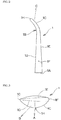
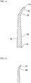
Fig. 1 is a front elevational view of a rotor blade showing an embodiment of the present invention; -
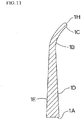
Fig. 2 is a right side elevational view thereof; -
Fig. 3 is a top plan view thereof; -
Fig. 4 is a bottom plan view thereof; -
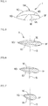
Fig. 5 is a sectional view taken along the line A-A inFig. 1 ; -
Fig. 6 is a sectional view taken along the line B-B inFig. 1 ; -
Fig. 7 is a sectional view taken along the line C-C inFig. 1 ; -
Fig. 8 is a sectional view taken along the line D-D inFig. 1 ; -
Fig. 9 is a sectional view taken along the line E-E inFig. 1 ; -
Fig. 10 is a sectional view taken along the line F-F inFig. 1 ; -
Fig. 11 is a sectional view taken along the line G-G inFig. 1 ; -
Fig. 12 is a sectional view taken along the line H-H inFig. 1 ; -
Fig. 13 is a sectional view taken along the line I-I inFig. 1 ; -
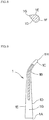
Fig. 14 is a front elevational view of a rotor to which three rotor blades of the present invention are fixed; and -
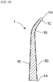
Fig. 15 is a side elevational view of a rotor blade showing variation of airflows. - Examples according to the present invention are described with the drawings as follows. The drawings show the best shape as a result of repeating experiments, and each numerical value range presents their permissible ranges for altering.
- In
Fig. 1 , arotor blade 1 is a lift type blade (it is simply referred to as "blade" below), and a shape of its front surface is shown in bilateral symmetry. It is also possible to use a rotor blade of which a front surface has an asymmetric shape. - The
front surface 1D of theblade 1 has a chord length which is gradually increased from ablade root 1A to a maximumchord length portion 1B, and the chord length at the maximumchord length portion 1B is within a range of 45 to 50 % of a rotation radius of theblade 1. - When the chord length is less than this range, a wind receiving area is small and a rotation efficiency of the
lift type blade 1 of which a blade end portion is formed into aninclined portion 1C is difficult to be raised. - When the chord length is more than 50 %, the rotation efficiency is difficult to be raised due to an influence of a turbulent flow occurred by a
blade 1 fitted to ahub 3 at a forward position in a rotation direction. - A ratio of the chord length of the
blade root 1A to that of the maximumchord length portion 1B on thefront surface 1D of theblade 1 is set at about one-third and so on, namely within a range of 30 to 35 %. - When the chord length of the
blade root 1A is more than this range, a passing property of airflow is lowered when rotating and a passing time is increased. When the chord length is less than this range, a passing speed of the airflow by Coanda effect and strength are decreased. - As shown in
Fig. 2 , thickness of theblade 1 is maximum at theblade root 1A and is gradually decreased to atip portion 1H in a side view, and thetip 1H is made into a semicircle shape. The thickness of the blade end portion is set at about one-third of the thickness of theblade root 1A and so on, namely within a range of 30 to 35 %. - An
inclined portion 1C is formed by inclining the blade end portion in a direction of a front surface from the maximumchord length portion 1B on thefront surface 1D. - This
inclined portion 1C is inclined in a direction perpendicular to the front surface ID, wherein the direction is shown by an arrow A inFig. 3 . When an attack angle is set at 17 degrees as an example, this arrow A direction is turned by about 17 degrees to a trailingedge 1G direction. - Therefore, the airflow moving from the
blade root 1A and passing through thefront surface 1D of theinclined portion 1C passes through in an intermediate direction (arrow B direction) between the direction of thetip portion 1H of thisinclined portion 1C (shown by an arrow A) and the direction of the trailingedge 1G in the rotation direction side. Due to a counteraction, a rotation efficiency of theblade 1 is increased. - In other words, when this
blade 1 rotates by receiving the airflow on the front surface ID, the airflow does not pass through in a rotating circle of theblade 1 in the direction of the back surface IE, and passes through in the direction of the back surface IE of theinclined portion 1C, that is, in an oblique direction between the counter-rotation direction and a centrifugal direction as shown by an arrow C inFigs. 1 and2 . Thus, a counteraction due to the airflow flowing in the arrow C direction inFig. 1 is directed to an opposite direction of the flowing direction, and theblade 1 is effectively rotated in the rotation direction faster than the wind speed. -
Fig. 5 is a sectional view taken along the line A-A inFig. 1 . This section corresponds to the maximumchord length portion 1B, a leading edge IF is formed into a semicircle shape, a diameter of the leading edge IF is the same as thickness of it, and this section is gradually thinned toward the trailingedge 1G. - The thickness of the blade end portion is set at about one-third of the chord length of the
blade root 1A. This numerical value is balanced by a factor in which thefront surface 1D is inclined by about 2 degrees in the direction of theback surface 1E. - A maximum thickness of the
leading edge 1F at the maximumchord length portion 1B is set at 12 % plus or minus 1 % of the chord length. Since the cross section of the leading edge IF has the semicircle shape, a relative flow flows smoothly even if the relative flow hits the leading edge IF from whatever direction. - In this way, it is possible to reduce resistance by making the attack angle close to 0 degree even if the chord length is long, but a torque is reduced. Thus, as shown in
Fig. 5 , when thefront surface 1D is inclined from the rotation direction by about 5 degrees such that the trailingedge 1G is arranged in theback surface 1E direction, it is also possible to smooth a counteraction due to the passing flow in the chord direction by the Coanda effect according to the rotation and the rotation due to the wind receiving. -
Fig. 6 is a sectional view taken along the line B-B inFig. 1 . The maximum thickness of the leading edge IF is 20 % plus or minus 2 % of the chord length. This thickness is about one-fourth when comparing with that of theblade root 1A shown inFig. 8 . Thus, the resistance when rotating is low. -
Fig. 7 is a sectional view taken along the line C-C inFig. 1 . The maximum thickness of the leading edge IF is 38 % plus or minus 2 % of the chord length. - Thus, even if the attack angle is 0 degree, it is possible to smooth the counteraction due to the passing flow in the chord direction by the Coanda effect according to the rotation and the rotation due to the wind receiving.
-
Fig. 8 is a sectional view taken along the line D-D inFig. 1 . The maximum thickness of the leading edge IF of theblade root 1A is 75 % plus or minus 2 % of the chord length as shown in the drawing. Thefront surface 1D is inclined such that the trailing edge is arranged in the back surface IE compared to an upper portion of thefront surface 1D. - When the chord length of the
blade root 1A is large, a crossing angle between thefront surface 1D of theblade root 1A and the rotation direction is small. It is preferable that this crossing angle between thefront surface 1D of theblade root 1A and the rotation direction is 45 degrees. When the crossing angle is less than 45 degrees, a force for pushing theblade 1 in the rotation direction by the airflow is reduced, and the torque is reduced. - In
Figs. 5 to 8 , the larger the ratio of the maximum thickness of the leading edge IF to the chord length is, the faster the flow speed by the Coanda effect occurring when rotating is. - Therefore, the flow speed passing through the
front surface 1D by the Coanda effect is faster at theblade root 1A than at theblade end portion 1H. - In
Fig. 1 , generally, a peripheral speed is faster at theblade end portion 1H than at theblade root 1A. Thus, since the airflow passing through the peripheral surface of the maximumchord length portion 1B with a high speed due to the Coanda effect is low in an air density, the airflow is low in air pressure and draws airflows of atmospheric pressure from the surroundings. - In
Figs. 5 to 8 , the thicker the maximum thickness of the leading edge IF, the faster the flow speed of the airflow passing through thefront surface 1D by the Coanda effect. Thus, a flow rate is increased proportional to the flow speed, and the torque of theblade 1 is increased due to a counteraction. - Moreover, since the high-speed flow is lower in air pressure than the surroundings, airflows in atmospheric pressure are drawn from the front side of the
front surface 1D to a backward portion behind a width center line S of a chord in the direction of the trailingedge 1G inFigs. 5 to 8 , and the rotation efficiency is increased. - Simultaneously, as shown in
Fig. 2 , since thefront surface 1D is inclined in the direction of the back surface IE from theblade root 1A to the maximumchord length portion 1B, the airflow flowing in the centrifugal direction on thefront surface 1D moves from theblade root 1A in the direction of thetip portion 1H, hits theinclined portion 1C, passes through in the arrow B direction inFig. 3 , pushes theblade 1 in the rotation direction due to the counteraction, and increases the torque. -
Fig. 14 is a front elevational view of therotor 2 in which theblades 1 are fixed to ahub 3. Theblades 1 are fixed to thehub 3 such that each attack angle at the respective maximumchord length portions 1B is set at 0 degree. - Conventionally, since the blade is twisted such that the attack angle is increased toward the
blade end portion 1H, cavitation occurs at theblade root 1A close to thehub 3 when rotating at a high speed. - In the present invention, although a twist is not seen in a side view as shown in
Fig. 2 , thefront surface 1D is gradually inclined in the direction of theback surface 1E by about 2 degrees from theblade root 1A to the maximumchord length portion 1B on the drawing by thinning theblade end portion 1H compared to theblade root 1A. Thus, the airflow easily moves from theblade root 1A in the direction of the maximumchord length portion 1B. - Moreover, since the blade end portion is thinned compared to the
blade root 1A, as shown inFigs. 5 to 8 , the trailingedge 1G is positioned at theback surface 1E side at theblade root 1A. The closer the position of the trailingedge 1G gets to the maximumchord length portion 1B, the more the position of the trailingedge 1G is shifted in the direction of thefront surface 1D. - In other words, a forward portion before the width center line S of the chord on the
front surface 1D is inclined in the direction of the back surface IE from theblade root 1A to thetip portion 1H, and a backward portion behind the width center line S of the chord is gradually shifted in the direction of thefront surface 1D from theblade root 1A to thetip portion 1H. - Thus, at a portion near the trailing
edge 1G on the chord, the closer the airflow moving from theblade root 1A in the direction of the maximumchord length portion 1B when rotating gets to the maximumchord length portion 1B, the more the airflow is shifted in the direction of the front surface. - As a result, the closer the airflow hitting the
front surface 1D of theblade 1 gets to the maximumchord length portion 1B from theblade root 1A, the more the airflow is increased in a wind pressure. Theinclined portion 1C is pressed by a strong wind power, and a rotational torque with an excellent efficiency can be obtained by a principle of leverage. - In
Fig. 15 , it is explained a relation between the inclination of the wholefront surface 1D and each change of the airflows by theinclined portion 1C. InFig. 15 , each airflow shown by arrows W1, W2, W3 reaches respective points a, b, e from a left side simultaneously. - A time in which the airflow shown by the arrow W2 reaches from the point b to the point d is the same as that in which the airflow shown by the arrow W1 reaches from the point a to the point d. Therefore, a speed in which the airflow W1 reaches from the point a to the point d is faster than that in which the airflow W2 reaches from the point b to the point d, and an air pressure is decreased according to the speed difference.
- The time in which the airflow shown by the arrow W2 reaches from the point b to the point d is the same as that in which the airflow shown by the arrow W3 reaches from the point e to the point f. Then, a time in which the airflow shown by the arrow W2 reaches from the point c to the point d is the same as that in which the airflow shown by the arrow W3 reaches from the point f to the point d. Therefore, an airflow between the points f and d is in a high speed and is in a low pressure.
- Accordingly, as a result that the
front surface 1D of theblade 1 is inclined in the direction of the back surface IE toward the maximumchord length portion 1B, it is possible to understand that the high-speed flow occurs between the points f to d, and that the airflows of low pressure concentrate on the maximumchord length portion 1B. - When the low air pressure occurs, airflows of atmospheric pressure surge from the surroundings and pass through in a high speed in the arrow C direction shown in
Fig. 2 and in the arrow B direction shown inFig. 3 , and the high-speed rotation of theblade 1 is accelerated in a high efficiency due to a counteraction. - In this way, the blade of the present invention has a unique structure such as that the maximum chord length is 300 % plus or minus 10 % of the chord length of the
blade root 1A, that the thickness of theblade end portion 1H is about one-third of that of theblade root 1A in a side view, that thefront surface 1D is inclined in the direction of theback surface 1E from theblade root 1A to the maximumchord length portion 1B, and that the trailingedge 1G in the backward portion behind the width center line S of the chord is gradually shifted in the direction of thefront surface 1D from theblade root 1A to the maximumchord length portion 1B. A total efficiency of these features accelerates the effect of rotation in the high efficiency. - The
blade 1 comprises the maximumchord length portion 1B which has a large chord length, a large wind receiving area and thickness smaller than that of ablade root 1A, and theblade 1 has a high rotation efficiency. Therefore, theblade 1 can be applied to a wind power generation system and a high generating efficiency can be obtained.
Claims (5)
- A rotor blade which is a lift type blade having a chord length gradually increased from a blade root to a blade end portion, comprising:a leading edge of which a maximum thickness is gradually decreased from the blade root to the blade end portion in a side view;a front surface gradually inclined in a direction of a back surface from the blade root to a maximum chord length portion; andan inclined portion formed of a blade end portion which is inclined in a front surface direction from the maximum chord length portion,wherein an airflow is directed from the blade root to the maximum chord length portion at where an air pressure is decreased when rotating.
- The rotor blade according to claim 1, wherein the front surface of the lift type blade is gradually inclined in the direction of the back surface from the blade root to the blade end portion, and a backward portion behind a width center line of a chord of the lift type blade is gradually shifted to the direction of the front surface from the blade root to the blade end portion.
- The rotor blade according to claim 1 or 2, wherein thickness of the blade root is 300 % plus or minus 10 % of thickness of the maximum chord length portion, wherein the blade end portion is the inclined portion inclined in the direction of the front surface from a front surface of the maximum chord length portion, and wherein airflows gathering to the blade root due to a difference among high-speed flows on the front surface by Coanda effect when rotating are naturally directed to the inclined portion.
- The rotor blade according to any one of claims 1 to 3, wherein the lift type blade is fixed to a hub of a rotor at an attack angle of 0 degree.
- The rotor blade according to any one of claims 1 to 4, wherein the maximum chord length of the blade end portion is within a range of 40 to 50 % of a rotation radius, a chord length of the blade root on the front surface is within a range of 30 to 35 % of the maximum chord length, the thickness in a side surface of the blade root is within a range of 72 to 76 % of the chord length of the blade root, and thickness of the blade end portion is within a range of 30 to 35 % of the thickness of the blade root.
Applications Claiming Priority (2)
| Application Number | Priority Date | Filing Date | Title |
|---|---|---|---|
| JP2016033037A JP7049050B2 (en) | 2016-02-24 | 2016-02-24 | Rotor blade |
| PCT/JP2016/086362 WO2017145488A1 (en) | 2016-02-24 | 2016-12-07 | Rotor blade |
Publications (3)
| Publication Number | Publication Date |
|---|---|
| EP3421780A1 true EP3421780A1 (en) | 2019-01-02 |
| EP3421780A4 EP3421780A4 (en) | 2019-10-30 |
| EP3421780B1 EP3421780B1 (en) | 2023-03-29 |
Family
ID=59686236
Family Applications (1)
| Application Number | Title | Priority Date | Filing Date |
|---|---|---|---|
| EP16891644.3A Active EP3421780B1 (en) | 2016-02-24 | 2016-12-07 | Rotor blade |
Country Status (7)
| Country | Link |
|---|---|
| US (1) | US11162472B2 (en) |
| EP (1) | EP3421780B1 (en) |
| JP (1) | JP7049050B2 (en) |
| KR (1) | KR102608949B1 (en) |
| CN (1) | CN108700027B (en) |
| MY (1) | MY196506A (en) |
| WO (1) | WO2017145488A1 (en) |
Families Citing this family (5)
| Publication number | Priority date | Publication date | Assignee | Title |
|---|---|---|---|---|
| JP7161827B2 (en) * | 2016-02-24 | 2022-10-27 | Ntn株式会社 | Wind power generation method and wind power generation device |
| JP7007841B2 (en) * | 2017-09-07 | 2022-01-25 | Ntn株式会社 | Rotor blade and horizontal axis turbine equipped with it |
| JP6426869B1 (en) | 2018-06-08 | 2018-11-21 | 株式会社グローバルエナジー | Horizontal axis rotor |
| US11999466B2 (en) | 2019-11-14 | 2024-06-04 | Skydio, Inc. | Ultra-wide-chord propeller |
| CN113266592A (en) * | 2021-07-06 | 2021-08-17 | 杭州老板电器股份有限公司 | Blade, impeller and fan |
Family Cites Families (13)
| Publication number | Priority date | Publication date | Assignee | Title |
|---|---|---|---|---|
| MXPA05007120A (en) * | 2003-01-02 | 2005-09-21 | Wobben Aloys | Rotor blade for a wind power plant. |
| US8128338B2 (en) | 2004-11-30 | 2012-03-06 | Kabushiki Kaisha Bellsion | Propeller and horizontal-axis wind turbine |
| JP4723264B2 (en) * | 2005-03-15 | 2011-07-13 | 株式会社ベルシオン | 3D rotor blade and horizontal axis wind turbine |
| JP4740580B2 (en) * | 2004-11-30 | 2011-08-03 | 株式会社ベルシオン | Horizontal axis wind turbine blades and horizontal axis wind turbine |
| BRPI0619723B1 (en) * | 2005-11-01 | 2018-06-12 | Global Energy Co., Ltd | SILENT PROPELLER |
| JP4939252B2 (en) | 2007-02-14 | 2012-05-23 | 株式会社ベルシオン | Wind hydraulic generator |
| CN101641519B (en) * | 2007-02-28 | 2012-09-05 | 歌美飒创新技术公司 | wind turbine blades |
| US8317483B2 (en) * | 2010-12-15 | 2012-11-27 | General Electric Company | Wind turbine rotor blade |
| JP5730003B2 (en) * | 2010-12-20 | 2015-06-03 | 株式会社ベルシオン | Fluid rotating wheel |
| JP5925997B2 (en) * | 2011-04-18 | 2016-05-25 | 株式会社ベルシオン | Blade of rotor for fluid equipment |
| JP5296141B2 (en) * | 2011-05-02 | 2013-09-25 | 株式会社ビルメン鹿児島 | Windmill wings for wind turbine generator |
| KR101216252B1 (en) * | 2012-04-13 | 2012-12-28 | 군산대학교산학협력단 | Aerogenerator blade of tip airfoil |
| US20150132130A1 (en) * | 2013-11-12 | 2015-05-14 | NAB & Associates, Inc. | Wind turbine noise and fatigue control |
-
2016
- 2016-02-24 JP JP2016033037A patent/JP7049050B2/en not_active Expired - Fee Related
- 2016-12-07 KR KR1020187027953A patent/KR102608949B1/en active Active
- 2016-12-07 MY MYPI2018702944A patent/MY196506A/en unknown
- 2016-12-07 EP EP16891644.3A patent/EP3421780B1/en active Active
- 2016-12-07 WO PCT/JP2016/086362 patent/WO2017145488A1/en not_active Ceased
- 2016-12-07 US US16/078,823 patent/US11162472B2/en not_active Expired - Fee Related
- 2016-12-07 CN CN201680082327.5A patent/CN108700027B/en not_active Expired - Fee Related
Also Published As
| Publication number | Publication date |
|---|---|
| US20190055918A1 (en) | 2019-02-21 |
| CN108700027B (en) | 2022-04-22 |
| EP3421780A4 (en) | 2019-10-30 |
| US11162472B2 (en) | 2021-11-02 |
| CN108700027A (en) | 2018-10-23 |
| WO2017145488A1 (en) | 2017-08-31 |
| KR102608949B1 (en) | 2023-11-30 |
| JP2017150375A (en) | 2017-08-31 |
| MY196506A (en) | 2023-04-18 |
| KR20180116405A (en) | 2018-10-24 |
| EP3421780B1 (en) | 2023-03-29 |
| JP7049050B2 (en) | 2022-04-06 |
Similar Documents
| Publication | Publication Date | Title |
|---|---|---|
| EP3421780B1 (en) | Rotor blade | |
| CN104976075B (en) | Vortex generators aligned with trailing edge features on wind turbine blades | |
| EP2997263B1 (en) | Axial fan | |
| US10288036B2 (en) | Rotor | |
| JP4740580B2 (en) | Horizontal axis wind turbine blades and horizontal axis wind turbine | |
| EP3006731B1 (en) | Rotor | |
| US20170370345A1 (en) | Fluid Turbine Rotor Blade with Winglet Design | |
| US20140127030A1 (en) | A turbine blade system | |
| CN101779037A (en) | Wind turbine blade | |
| JP2012052443A (en) | Propeller fan | |
| EP3472456B1 (en) | Wind turbine blade with tip end serrations | |
| KR102452988B1 (en) | transverse rotor | |
| JP7007841B2 (en) | Rotor blade and horizontal axis turbine equipped with it | |
| CN108698678A (en) | Horizontal axis rotor and the boat for having horizontal axis rotor | |
| RU2278058C2 (en) | Propeller blade | |
| KR101245738B1 (en) | Propeller structure and ship including the same | |
| RU2585209C1 (en) | Screw | |
| JP2018115607A (en) | Rotor | |
| US20220082077A1 (en) | Rotor blade for a wind turbine | |
| RU2376202C2 (en) | Rotor blade | |
| JP2018091281A (en) | Horizontal shaft rotor | |
| CN103670911A (en) | Blade of wind driven generator | |
| JP2012207554A (en) | Blade for windmill and blade for propeller | |
| IES86367Y1 (en) | A blade for a rotary machine |
Legal Events
| Date | Code | Title | Description |
|---|---|---|---|
| STAA | Information on the status of an ep patent application or granted ep patent |
Free format text: STATUS: THE INTERNATIONAL PUBLICATION HAS BEEN MADE |
|
| PUAI | Public reference made under article 153(3) epc to a published international application that has entered the european phase |
Free format text: ORIGINAL CODE: 0009012 |
|
| STAA | Information on the status of an ep patent application or granted ep patent |
Free format text: STATUS: REQUEST FOR EXAMINATION WAS MADE |
|
| 17P | Request for examination filed |
Effective date: 20180921 |
|
| AK | Designated contracting states |
Kind code of ref document: A1 Designated state(s): AL AT BE BG CH CY CZ DE DK EE ES FI FR GB GR HR HU IE IS IT LI LT LU LV MC MK MT NL NO PL PT RO RS SE SI SK SM TR |
|
| AX | Request for extension of the european patent |
Extension state: BA ME |
|
| DAV | Request for validation of the european patent (deleted) | ||
| DAX | Request for extension of the european patent (deleted) | ||
| RAP1 | Party data changed (applicant data changed or rights of an application transferred) |
Owner name: NTN CORPORATION |
|
| A4 | Supplementary search report drawn up and despatched |
Effective date: 20190927 |
|
| RIC1 | Information provided on ipc code assigned before grant |
Ipc: F03D 1/06 20060101AFI20190923BHEP |
|
| STAA | Information on the status of an ep patent application or granted ep patent |
Free format text: STATUS: EXAMINATION IS IN PROGRESS |
|
| 17Q | First examination report despatched |
Effective date: 20201112 |
|
| GRAP | Despatch of communication of intention to grant a patent |
Free format text: ORIGINAL CODE: EPIDOSNIGR1 |
|
| STAA | Information on the status of an ep patent application or granted ep patent |
Free format text: STATUS: GRANT OF PATENT IS INTENDED |
|
| INTG | Intention to grant announced |
Effective date: 20221026 |
|
| GRAS | Grant fee paid |
Free format text: ORIGINAL CODE: EPIDOSNIGR3 |
|
| GRAA | (expected) grant |
Free format text: ORIGINAL CODE: 0009210 |
|
| STAA | Information on the status of an ep patent application or granted ep patent |
Free format text: STATUS: THE PATENT HAS BEEN GRANTED |
|
| AK | Designated contracting states |
Kind code of ref document: B1 Designated state(s): AL AT BE BG CH CY CZ DE DK EE ES FI FR GB GR HR HU IE IS IT LI LT LU LV MC MK MT NL NO PL PT RO RS SE SI SK SM TR |
|
| REG | Reference to a national code |
Ref country code: CH Ref legal event code: EP |
|
| REG | Reference to a national code |
Ref country code: AT Ref legal event code: REF Ref document number: 1556829 Country of ref document: AT Kind code of ref document: T Effective date: 20230415 |
|
| REG | Reference to a national code |
Ref country code: DE Ref legal event code: R096 Ref document number: 602016078593 Country of ref document: DE |
|
| REG | Reference to a national code |
Ref country code: IE Ref legal event code: FG4D |
|
| REG | Reference to a national code |
Ref country code: LT Ref legal event code: MG9D |
|
| PG25 | Lapsed in a contracting state [announced via postgrant information from national office to epo] |
Ref country code: RS Free format text: LAPSE BECAUSE OF FAILURE TO SUBMIT A TRANSLATION OF THE DESCRIPTION OR TO PAY THE FEE WITHIN THE PRESCRIBED TIME-LIMIT Effective date: 20230329 Ref country code: NO Free format text: LAPSE BECAUSE OF FAILURE TO SUBMIT A TRANSLATION OF THE DESCRIPTION OR TO PAY THE FEE WITHIN THE PRESCRIBED TIME-LIMIT Effective date: 20230629 Ref country code: LV Free format text: LAPSE BECAUSE OF FAILURE TO SUBMIT A TRANSLATION OF THE DESCRIPTION OR TO PAY THE FEE WITHIN THE PRESCRIBED TIME-LIMIT Effective date: 20230329 Ref country code: LT Free format text: LAPSE BECAUSE OF FAILURE TO SUBMIT A TRANSLATION OF THE DESCRIPTION OR TO PAY THE FEE WITHIN THE PRESCRIBED TIME-LIMIT Effective date: 20230329 Ref country code: HR Free format text: LAPSE BECAUSE OF FAILURE TO SUBMIT A TRANSLATION OF THE DESCRIPTION OR TO PAY THE FEE WITHIN THE PRESCRIBED TIME-LIMIT Effective date: 20230329 |
|
| REG | Reference to a national code |
Ref country code: NL Ref legal event code: MP Effective date: 20230329 |
|
| REG | Reference to a national code |
Ref country code: AT Ref legal event code: MK05 Ref document number: 1556829 Country of ref document: AT Kind code of ref document: T Effective date: 20230329 |
|
| PG25 | Lapsed in a contracting state [announced via postgrant information from national office to epo] |
Ref country code: SE Free format text: LAPSE BECAUSE OF FAILURE TO SUBMIT A TRANSLATION OF THE DESCRIPTION OR TO PAY THE FEE WITHIN THE PRESCRIBED TIME-LIMIT Effective date: 20230329 Ref country code: NL Free format text: LAPSE BECAUSE OF FAILURE TO SUBMIT A TRANSLATION OF THE DESCRIPTION OR TO PAY THE FEE WITHIN THE PRESCRIBED TIME-LIMIT Effective date: 20230329 Ref country code: GR Free format text: LAPSE BECAUSE OF FAILURE TO SUBMIT A TRANSLATION OF THE DESCRIPTION OR TO PAY THE FEE WITHIN THE PRESCRIBED TIME-LIMIT Effective date: 20230630 Ref country code: FI Free format text: LAPSE BECAUSE OF FAILURE TO SUBMIT A TRANSLATION OF THE DESCRIPTION OR TO PAY THE FEE WITHIN THE PRESCRIBED TIME-LIMIT Effective date: 20230329 |
|
| PG25 | Lapsed in a contracting state [announced via postgrant information from national office to epo] |
Ref country code: SM Free format text: LAPSE BECAUSE OF FAILURE TO SUBMIT A TRANSLATION OF THE DESCRIPTION OR TO PAY THE FEE WITHIN THE PRESCRIBED TIME-LIMIT Effective date: 20230329 Ref country code: RO Free format text: LAPSE BECAUSE OF FAILURE TO SUBMIT A TRANSLATION OF THE DESCRIPTION OR TO PAY THE FEE WITHIN THE PRESCRIBED TIME-LIMIT Effective date: 20230329 Ref country code: PT Free format text: LAPSE BECAUSE OF FAILURE TO SUBMIT A TRANSLATION OF THE DESCRIPTION OR TO PAY THE FEE WITHIN THE PRESCRIBED TIME-LIMIT Effective date: 20230731 Ref country code: ES Free format text: LAPSE BECAUSE OF FAILURE TO SUBMIT A TRANSLATION OF THE DESCRIPTION OR TO PAY THE FEE WITHIN THE PRESCRIBED TIME-LIMIT Effective date: 20230329 Ref country code: EE Free format text: LAPSE BECAUSE OF FAILURE TO SUBMIT A TRANSLATION OF THE DESCRIPTION OR TO PAY THE FEE WITHIN THE PRESCRIBED TIME-LIMIT Effective date: 20230329 Ref country code: AT Free format text: LAPSE BECAUSE OF FAILURE TO SUBMIT A TRANSLATION OF THE DESCRIPTION OR TO PAY THE FEE WITHIN THE PRESCRIBED TIME-LIMIT Effective date: 20230329 |
|
| PG25 | Lapsed in a contracting state [announced via postgrant information from national office to epo] |
Ref country code: SK Free format text: LAPSE BECAUSE OF FAILURE TO SUBMIT A TRANSLATION OF THE DESCRIPTION OR TO PAY THE FEE WITHIN THE PRESCRIBED TIME-LIMIT Effective date: 20230329 Ref country code: PL Free format text: LAPSE BECAUSE OF FAILURE TO SUBMIT A TRANSLATION OF THE DESCRIPTION OR TO PAY THE FEE WITHIN THE PRESCRIBED TIME-LIMIT Effective date: 20230329 Ref country code: IS Free format text: LAPSE BECAUSE OF FAILURE TO SUBMIT A TRANSLATION OF THE DESCRIPTION OR TO PAY THE FEE WITHIN THE PRESCRIBED TIME-LIMIT Effective date: 20230729 |
|
| REG | Reference to a national code |
Ref country code: DE Ref legal event code: R097 Ref document number: 602016078593 Country of ref document: DE |
|
| PG25 | Lapsed in a contracting state [announced via postgrant information from national office to epo] |
Ref country code: DK Free format text: LAPSE BECAUSE OF FAILURE TO SUBMIT A TRANSLATION OF THE DESCRIPTION OR TO PAY THE FEE WITHIN THE PRESCRIBED TIME-LIMIT Effective date: 20230329 Ref country code: CZ Free format text: LAPSE BECAUSE OF FAILURE TO SUBMIT A TRANSLATION OF THE DESCRIPTION OR TO PAY THE FEE WITHIN THE PRESCRIBED TIME-LIMIT Effective date: 20230329 |
|
| PGFP | Annual fee paid to national office [announced via postgrant information from national office to epo] |
Ref country code: FR Payment date: 20231108 Year of fee payment: 8 Ref country code: DE Payment date: 20231031 Year of fee payment: 8 |
|
| PLBE | No opposition filed within time limit |
Free format text: ORIGINAL CODE: 0009261 |
|
| STAA | Information on the status of an ep patent application or granted ep patent |
Free format text: STATUS: NO OPPOSITION FILED WITHIN TIME LIMIT |
|
| 26N | No opposition filed |
Effective date: 20240103 |
|
| PG25 | Lapsed in a contracting state [announced via postgrant information from national office to epo] |
Ref country code: SI Free format text: LAPSE BECAUSE OF FAILURE TO SUBMIT A TRANSLATION OF THE DESCRIPTION OR TO PAY THE FEE WITHIN THE PRESCRIBED TIME-LIMIT Effective date: 20230329 |
|
| PG25 | Lapsed in a contracting state [announced via postgrant information from national office to epo] |
Ref country code: SI Free format text: LAPSE BECAUSE OF FAILURE TO SUBMIT A TRANSLATION OF THE DESCRIPTION OR TO PAY THE FEE WITHIN THE PRESCRIBED TIME-LIMIT Effective date: 20230329 Ref country code: IT Free format text: LAPSE BECAUSE OF FAILURE TO SUBMIT A TRANSLATION OF THE DESCRIPTION OR TO PAY THE FEE WITHIN THE PRESCRIBED TIME-LIMIT Effective date: 20230329 |
|
| REG | Reference to a national code |
Ref country code: CH Ref legal event code: PL |
|
| PG25 | Lapsed in a contracting state [announced via postgrant information from national office to epo] |
Ref country code: LU Free format text: LAPSE BECAUSE OF NON-PAYMENT OF DUE FEES Effective date: 20231207 |
|
| PG25 | Lapsed in a contracting state [announced via postgrant information from national office to epo] |
Ref country code: MC Free format text: LAPSE BECAUSE OF FAILURE TO SUBMIT A TRANSLATION OF THE DESCRIPTION OR TO PAY THE FEE WITHIN THE PRESCRIBED TIME-LIMIT Effective date: 20230329 |
|
| GBPC | Gb: european patent ceased through non-payment of renewal fee |
Effective date: 20231207 |
|
| REG | Reference to a national code |
Ref country code: BE Ref legal event code: MM Effective date: 20231231 |
|
| PG25 | Lapsed in a contracting state [announced via postgrant information from national office to epo] |
Ref country code: MC Free format text: LAPSE BECAUSE OF FAILURE TO SUBMIT A TRANSLATION OF THE DESCRIPTION OR TO PAY THE FEE WITHIN THE PRESCRIBED TIME-LIMIT Effective date: 20230329 Ref country code: LU Free format text: LAPSE BECAUSE OF NON-PAYMENT OF DUE FEES Effective date: 20231207 |
|
| REG | Reference to a national code |
Ref country code: IE Ref legal event code: MM4A |
|
| PG25 | Lapsed in a contracting state [announced via postgrant information from national office to epo] |
Ref country code: IE Free format text: LAPSE BECAUSE OF NON-PAYMENT OF DUE FEES Effective date: 20231207 |
|
| PG25 | Lapsed in a contracting state [announced via postgrant information from national office to epo] |
Ref country code: GB Free format text: LAPSE BECAUSE OF NON-PAYMENT OF DUE FEES Effective date: 20231207 |
|
| PG25 | Lapsed in a contracting state [announced via postgrant information from national office to epo] |
Ref country code: BE Free format text: LAPSE BECAUSE OF NON-PAYMENT OF DUE FEES Effective date: 20231231 |
|
| PG25 | Lapsed in a contracting state [announced via postgrant information from national office to epo] |
Ref country code: CH Free format text: LAPSE BECAUSE OF NON-PAYMENT OF DUE FEES Effective date: 20231231 |
|
| PG25 | Lapsed in a contracting state [announced via postgrant information from national office to epo] |
Ref country code: IE Free format text: LAPSE BECAUSE OF NON-PAYMENT OF DUE FEES Effective date: 20231207 Ref country code: GB Free format text: LAPSE BECAUSE OF NON-PAYMENT OF DUE FEES Effective date: 20231207 Ref country code: CH Free format text: LAPSE BECAUSE OF NON-PAYMENT OF DUE FEES Effective date: 20231231 Ref country code: BE Free format text: LAPSE BECAUSE OF NON-PAYMENT OF DUE FEES Effective date: 20231231 |
|
| PG25 | Lapsed in a contracting state [announced via postgrant information from national office to epo] |
Ref country code: BG Free format text: LAPSE BECAUSE OF FAILURE TO SUBMIT A TRANSLATION OF THE DESCRIPTION OR TO PAY THE FEE WITHIN THE PRESCRIBED TIME-LIMIT Effective date: 20230329 |
|
| PG25 | Lapsed in a contracting state [announced via postgrant information from national office to epo] |
Ref country code: BG Free format text: LAPSE BECAUSE OF FAILURE TO SUBMIT A TRANSLATION OF THE DESCRIPTION OR TO PAY THE FEE WITHIN THE PRESCRIBED TIME-LIMIT Effective date: 20230329 |
|
| REG | Reference to a national code |
Ref country code: DE Ref legal event code: R119 Ref document number: 602016078593 Country of ref document: DE |
|
| PG25 | Lapsed in a contracting state [announced via postgrant information from national office to epo] |
Ref country code: CY Free format text: LAPSE BECAUSE OF FAILURE TO SUBMIT A TRANSLATION OF THE DESCRIPTION OR TO PAY THE FEE WITHIN THE PRESCRIBED TIME-LIMIT; INVALID AB INITIO Effective date: 20161207 |
|
| PG25 | Lapsed in a contracting state [announced via postgrant information from national office to epo] |
Ref country code: HU Free format text: LAPSE BECAUSE OF FAILURE TO SUBMIT A TRANSLATION OF THE DESCRIPTION OR TO PAY THE FEE WITHIN THE PRESCRIBED TIME-LIMIT; INVALID AB INITIO Effective date: 20161207 |
|
| PG25 | Lapsed in a contracting state [announced via postgrant information from national office to epo] |
Ref country code: DE Free format text: LAPSE BECAUSE OF NON-PAYMENT OF DUE FEES Effective date: 20250701 |
|
| PG25 | Lapsed in a contracting state [announced via postgrant information from national office to epo] |
Ref country code: FR Free format text: LAPSE BECAUSE OF NON-PAYMENT OF DUE FEES Effective date: 20241231 |
|
| PG25 | Lapsed in a contracting state [announced via postgrant information from national office to epo] |
Ref country code: TR Free format text: LAPSE BECAUSE OF FAILURE TO SUBMIT A TRANSLATION OF THE DESCRIPTION OR TO PAY THE FEE WITHIN THE PRESCRIBED TIME-LIMIT Effective date: 20230329 |