EP3421734A1 - Preventing electrical breakdown - Google Patents
Preventing electrical breakdown Download PDFInfo
- Publication number
- EP3421734A1 EP3421734A1 EP18170239.0A EP18170239A EP3421734A1 EP 3421734 A1 EP3421734 A1 EP 3421734A1 EP 18170239 A EP18170239 A EP 18170239A EP 3421734 A1 EP3421734 A1 EP 3421734A1
- Authority
- EP
- European Patent Office
- Prior art keywords
- electric machine
- casing
- vacuum pump
- pressure
- seal
- Prior art date
- Legal status (The legal status is an assumption and is not a legal conclusion. Google has not performed a legal analysis and makes no representation as to the accuracy of the status listed.)
- Granted
Links
Images


Classifications
-
- B—PERFORMING OPERATIONS; TRANSPORTING
- B64—AIRCRAFT; AVIATION; COSMONAUTICS
- B64D—EQUIPMENT FOR FITTING IN OR TO AIRCRAFT; FLIGHT SUITS; PARACHUTES; ARRANGEMENT OR MOUNTING OF POWER PLANTS OR PROPULSION TRANSMISSIONS IN AIRCRAFT
- B64D33/00—Arrangement in aircraft of power plant parts or auxiliaries not otherwise provided for
-
- H—ELECTRICITY
- H02—GENERATION; CONVERSION OR DISTRIBUTION OF ELECTRIC POWER
- H02K—DYNAMO-ELECTRIC MACHINES
- H02K5/00—Casings; Enclosures; Supports
- H02K5/04—Casings or enclosures characterised by the shape, form or construction thereof
-
- B—PERFORMING OPERATIONS; TRANSPORTING
- B64—AIRCRAFT; AVIATION; COSMONAUTICS
- B64D—EQUIPMENT FOR FITTING IN OR TO AIRCRAFT; FLIGHT SUITS; PARACHUTES; ARRANGEMENT OR MOUNTING OF POWER PLANTS OR PROPULSION TRANSMISSIONS IN AIRCRAFT
- B64D27/00—Arrangement or mounting of power plants in aircraft; Aircraft characterised by the type or position of power plants
- B64D27/02—Aircraft characterised by the type or position of power plants
- B64D27/30—Aircraft characterised by electric power plants
- B64D27/34—All-electric aircraft
-
- B—PERFORMING OPERATIONS; TRANSPORTING
- B64—AIRCRAFT; AVIATION; COSMONAUTICS
- B64D—EQUIPMENT FOR FITTING IN OR TO AIRCRAFT; FLIGHT SUITS; PARACHUTES; ARRANGEMENT OR MOUNTING OF POWER PLANTS OR PROPULSION TRANSMISSIONS IN AIRCRAFT
- B64D31/00—Power plant control systems; Arrangement of power plant control systems in aircraft
- B64D31/16—Power plant control systems; Arrangement of power plant control systems in aircraft for electric power plants
-
- B—PERFORMING OPERATIONS; TRANSPORTING
- B64—AIRCRAFT; AVIATION; COSMONAUTICS
- B64D—EQUIPMENT FOR FITTING IN OR TO AIRCRAFT; FLIGHT SUITS; PARACHUTES; ARRANGEMENT OR MOUNTING OF POWER PLANTS OR PROPULSION TRANSMISSIONS IN AIRCRAFT
- B64D35/00—Transmitting power from power plants to propellers or rotors; Arrangements of transmissions
- B64D35/02—Transmitting power from power plants to propellers or rotors; Arrangements of transmissions specially adapted for specific power plants
- B64D35/021—Transmitting power from power plants to propellers or rotors; Arrangements of transmissions specially adapted for specific power plants for electric power plants
-
- F—MECHANICAL ENGINEERING; LIGHTING; HEATING; WEAPONS; BLASTING
- F01—MACHINES OR ENGINES IN GENERAL; ENGINE PLANTS IN GENERAL; STEAM ENGINES
- F01D—NON-POSITIVE DISPLACEMENT MACHINES OR ENGINES, e.g. STEAM TURBINES
- F01D15/00—Adaptations of machines or engines for special use; Combinations of engines with devices driven thereby
- F01D15/10—Adaptations for driving, or combinations with, electric generators
-
- F—MECHANICAL ENGINEERING; LIGHTING; HEATING; WEAPONS; BLASTING
- F04—POSITIVE - DISPLACEMENT MACHINES FOR LIQUIDS; PUMPS FOR LIQUIDS OR ELASTIC FLUIDS
- F04C—ROTARY-PISTON, OR OSCILLATING-PISTON, POSITIVE-DISPLACEMENT MACHINES FOR LIQUIDS; ROTARY-PISTON, OR OSCILLATING-PISTON, POSITIVE-DISPLACEMENT PUMPS
- F04C2/00—Rotary-piston machines or pumps
- F04C2/30—Rotary-piston machines or pumps having the characteristics covered by two or more groups F04C2/02, F04C2/08, F04C2/22, F04C2/24 or having the characteristics covered by one of these groups together with some other type of movement between co-operating members
- F04C2/34—Rotary-piston machines or pumps having the characteristics covered by two or more groups F04C2/02, F04C2/08, F04C2/22, F04C2/24 or having the characteristics covered by one of these groups together with some other type of movement between co-operating members having the movement defined in groups F04C2/08 or F04C2/22 and relative reciprocation between the co-operating members
- F04C2/344—Rotary-piston machines or pumps having the characteristics covered by two or more groups F04C2/02, F04C2/08, F04C2/22, F04C2/24 or having the characteristics covered by one of these groups together with some other type of movement between co-operating members having the movement defined in groups F04C2/08 or F04C2/22 and relative reciprocation between the co-operating members with vanes reciprocating with respect to the inner member
-
- F—MECHANICAL ENGINEERING; LIGHTING; HEATING; WEAPONS; BLASTING
- F04—POSITIVE - DISPLACEMENT MACHINES FOR LIQUIDS; PUMPS FOR LIQUIDS OR ELASTIC FLUIDS
- F04D—NON-POSITIVE-DISPLACEMENT PUMPS
- F04D25/00—Pumping installations or systems
- F04D25/02—Units comprising pumps and their driving means
- F04D25/06—Units comprising pumps and their driving means the pump being electrically driven
-
- H—ELECTRICITY
- H02—GENERATION; CONVERSION OR DISTRIBUTION OF ELECTRIC POWER
- H02K—DYNAMO-ELECTRIC MACHINES
- H02K5/00—Casings; Enclosures; Supports
- H02K5/04—Casings or enclosures characterised by the shape, form or construction thereof
- H02K5/12—Casings or enclosures characterised by the shape, form or construction thereof specially adapted for operating in liquid or gas
- H02K5/124—Sealing of shafts
-
- B—PERFORMING OPERATIONS; TRANSPORTING
- B64—AIRCRAFT; AVIATION; COSMONAUTICS
- B64D—EQUIPMENT FOR FITTING IN OR TO AIRCRAFT; FLIGHT SUITS; PARACHUTES; ARRANGEMENT OR MOUNTING OF POWER PLANTS OR PROPULSION TRANSMISSIONS IN AIRCRAFT
- B64D27/00—Arrangement or mounting of power plants in aircraft; Aircraft characterised by the type or position of power plants
- B64D27/02—Aircraft characterised by the type or position of power plants
- B64D27/026—Aircraft characterised by the type or position of power plants comprising different types of power plants, e.g. combination of a piston engine and a gas-turbine
-
- B—PERFORMING OPERATIONS; TRANSPORTING
- B64—AIRCRAFT; AVIATION; COSMONAUTICS
- B64D—EQUIPMENT FOR FITTING IN OR TO AIRCRAFT; FLIGHT SUITS; PARACHUTES; ARRANGEMENT OR MOUNTING OF POWER PLANTS OR PROPULSION TRANSMISSIONS IN AIRCRAFT
- B64D27/00—Arrangement or mounting of power plants in aircraft; Aircraft characterised by the type or position of power plants
- B64D27/02—Aircraft characterised by the type or position of power plants
- B64D27/10—Aircraft characterised by the type or position of power plants of gas-turbine type
-
- Y—GENERAL TAGGING OF NEW TECHNOLOGICAL DEVELOPMENTS; GENERAL TAGGING OF CROSS-SECTIONAL TECHNOLOGIES SPANNING OVER SEVERAL SECTIONS OF THE IPC; TECHNICAL SUBJECTS COVERED BY FORMER USPC CROSS-REFERENCE ART COLLECTIONS [XRACs] AND DIGESTS
- Y02—TECHNOLOGIES OR APPLICATIONS FOR MITIGATION OR ADAPTATION AGAINST CLIMATE CHANGE
- Y02T—CLIMATE CHANGE MITIGATION TECHNOLOGIES RELATED TO TRANSPORTATION
- Y02T50/00—Aeronautics or air transport
- Y02T50/60—Efficient propulsion technologies, e.g. for aircraft
Definitions
- This disclosure relates to the prevention of electrical arcing in electric machines in gaseous environments in which electrical breakdown may occur.
- the dielectric strength of air is typically in the region of megavolts. However, in regions of low air pressure, such as experienced by aircraft at cruise altitude, the dielectric strength may drop to the order of only hundreds of volts.
- Electric machines are typically subjected to voltage derating as altitude increases to prevent the likelihood of electrical breakdown and the attendant phenomena such as arcing and corona, which may cause catastrophic failure modes.
- the invention is directed towards an electric machine for use in an aircraft, and an aircraft comprising the same.
- the electric machine comprises a casing containing electromechanical components, a shaft which extends outside of the casing, a seal to seal the casing around the shaft, and a depressurisation system configured to depressurise the casing below an external gas pressure to prevent electrical breakdown within the gas the casing.
- the components liable to be damaged by electrical breakdown phenomena such as arcing and corona are sealed in a casing depressurised by the depressurisation system, and work may be performed by the electric machine upon external systems via its shaft.
- the electric machine may be configured as an electric motor or an electric generator, and may operate using alternating or direct current.
- the seal may comprise a labyrinth seal or a dry gas seal, or combination of the two.
- the depressurisation system When installed in an aircraft, the depressurisation system will operate to reduce the pressure inside the casing of the electric machine below the external gas pressure. Given typical cruise altitudes, the external gas pressure will be low and thus the breakdown voltage will also be low. This may lead to electrical breakdown events. Further reduction of the gas pressure within the casing, however, results in a greater mean free path between molecules within the gas within the casing, thereby reducing the likelihood of collisions. This therefore increases the voltage required for electron avalanche initiation to a point greater than the peak operational voltage within the casing, thereby preventing electrical breakdown.
- the electric machine may form part of an engine on the aircraft.
- FIG. 1 A block diagram illustrating an embodiment is shown in Figure 1 , in which an electric machine is shown generally at 101.
- the electric machine 101 comprises a depressurisation system 102.
- the depressurisation system 102 operates to depressurise a casing 103 of the electric machine 101 below an external pressure of the environment 104 in which the electric machine 101 is located.
- the casing 103 houses electromechanical components (not shown) which effect the conversion of electrical power into work upon a shaft 105, or vice versa depending upon the assigned role of the electric machine 101, for example whether it is to operate as a motor or generator. It will be appreciated that the exact configuration of the electromechanical components within the casing 103 will differ according to the type of the electric machine as implemented, and thus may include coils, magnets, brushes, springs, commutators, power electronics, etc.
- a seal 106 is provided to seal the casing around the shaft. Whilst the shaft 105 is shown extending out of only one end of the casing, it will be appreciated that the principles of the present invention may be extended to electric machines in which the shaft extends the full way through the casing, thus having what are commonly referred to as working and non-working ends. In such an implementation, another seal 106 would be provided to seal the casing around the two ends of the shaft.
- the seal 106 comprises a labyrinth seal.
- Labyrinth seals are characterised by a series of annular orifices used to seal a region of high pressure from one of low pressure. When gas flows from the high pressure side to the low pressure side of the seal, turbulence is caused by each annulus of the seal. Whilst this serves to minimise leakage, it does not entirely prevent it.
- the depressurisation system 102 operates to maintain the pressure in the casing 103 despite any leakage from environment 104 through the labyrinth seal and into the casing 103.
- the seal 106 comprises a dry gas seal.
- Such seals feature zones between the stationary face of the casing and rotating face of the shaft, into which gas is pumped. When the pressure of gas in these zones exceeds the static pressure holding the faces together, the faces separate by a thin layer of gas. Dry gas seals are supplied gas at pressure via an inlet, and have an outlet for seal gas to be vented. As the zones are small, the pressure in them tends to be greater than that in the environment 104, and thus there is little leakage of gas from environment 104 through the seal 106 and into the casing 103 in such an implementation.
- the depressurisation system 102 comprises a vacuum pump 201 driven by the shaft 105.
- the vacuum pump 201 is a positive-displacement vacuum pump.
- the positive-displacement pump is a rotary vane pump.
- the pump may be any other type of positive-displacement device such as a Roots blower.
- the vacuum pump is a centrifugal-type vacuum pump such as a radial inflow pump, or any other suitable type of vacuum pump.
- the vacuum pump may be multi-stage.
- a controller 202 and a pressure sensor 203 within the casing are provided.
- the pressure sensor 203 is configured to provide the controller 203 with a signal indicative of the pressure therein, which the controller 202 is configured to utilise to control operation of the vacuum pump by means of a clutch 204.
- the clutch 204 is actuated by a solenoid (not shown) connected with the controller 202, but it will be appreciated that other arrangements are possible to achieve activation/deactivation of the vacuum pump 201.
- the controller 202 is an analog controller configured to implement a prescribed control loop.
- the controller may be a digital controller with software-defined logic to achieve the desired control over the pressure in the casing 103.
- the controller in the latter case may form part of another sub-system in the wider installation the electric machine 101 forms part of.
- the control loop in the present example operates to compare the current pressure within the casing 103 to a prescribed threshold, above which electrical breakdown may occur. If the current pressure is determined to be below the threshold, the vacuum pump is enabled (i.e. the controller 202 allows to evacuate the casing 103) by engaging the clutch 204. If the current pressure is determined to be above the threshold, the vacuum pump is disabled by disengaging the clutch 204 (i.e. the controller 202 prevents it from evacuating the casing 103).
- a degree of hysteresis is included in the control loop to prevent over-actuation of the clutch 204 and vacuum pump 201.
- the vacuum pump 201 is only disabled once the pressure in the casing 103 is below the threshold pressure, less a lag value.
- the pressure will rise and approach the threshold, leading to the vacuum pump 201 being enabled by the controller 202 to depressurise the casing 103.
- Such a control loop may be implemented using a Schmitt trigger or similar, or as one or more conditional statements in a software implementation.
- the vacuum pump 201 is, in the present example, geared to the shaft 105 in order to drive the pump at the requisite angular rate to evacuate the casing 103. In the present example, this is achieved by a combination of a gear 205 on the shaft 105 meshed with a pinion 206 to drive the vacuum pump 201 via the clutch 204. It will be appreciated that the gear ratio will be in practice be dependent upon a combination of the angular rate required for the vacuum pump 201, and the operational rate of the electric machine 101. In a specific embodiment, the gear system used to connect the vacuum pump to the shaft is a magnetic gear.
- the vacuum pump 201 may instead be geared to the shaft using a variable transmission, possibly a variable magnetic gear.
- the clutch 204 may be omitted, and the vacuum pump's speed and therefore pressure ratio varied by the controller 202 to maintain the pressure in the casing 103 at a fixed value, or within an acceptable defined range.
- Gearing may be omitted, of course, if the electric machine 101 is to operate at same angular rate as required by the vacuum pump 201.
- the depressurisation system 102 comprises vacuum pump 201, but in an electrically-driven configuration in which it is driven by a motor 301.
- the motor 301 operates under the control of controller 202 which, in a similar way as described previously with reference to Figure 2 , may either enable or disable it in response to the output of pressure sensor 203 in the casing 103.
- the controller 202 may vary the speed of the motor 301 so as to maintain the pressure in the casing 103 at a fixed value or within an acceptable defined range.
- the motor 301 in this example operates at a much lower voltage than the electromechanical components in the casing 103. In this way, it is able to operate in low pressure environments such as may be encountered at aircraft cruise altitude without experiencing electrical breakdown, whereas breakdown could occur between the components in the casing 103 without depressurisation due to the higher voltages therein.
- the motor 301 could, in an alternative embodiment, be itself depressurised should electrical breakdown be possible due to its specification and operating environment.
- the casing 103 may be depressurised by the vacuum pump 201 driven by the motor 301.
- the electric machine 101 form part of an on-demand system in an aircraft in which it would not be running constantly.
- the electric machine 101 form part of a wider system that is only started and used in low-pressure environments, rather than being started at, say, sea level and transitioning to a higher altitude.
- the electric machine 101 of the present invention and the principles it embodies may be used in any gaseous environment which, when combined with the specification of the electromechanical components within the casing 104, is liable to cause electrical breakdown therein. This may be anticipated by application of Paschen's law. Thus, in terms of the parameters that may cause this, the possibility of electrical breakdown occurring may be ascribed to one or more of the external gas pressure within the environment 105, the peak voltages within the casing 104, and/or the minimum distance between electrodes within the casing 104. Thus, for example, the electric machine 101 may indeed be used in applications at, say, standard temperature and pressure, if the peak voltage and minimum distance are such that electrical breakdown may still occur.
Landscapes
- Engineering & Computer Science (AREA)
- Mechanical Engineering (AREA)
- Aviation & Aerospace Engineering (AREA)
- General Engineering & Computer Science (AREA)
- Power Engineering (AREA)
- Connection Of Motors, Electrical Generators, Mechanical Devices, And The Like (AREA)
- Control Of Positive-Displacement Air Blowers (AREA)
- Compressors, Vaccum Pumps And Other Relevant Systems (AREA)
- Motor Or Generator Frames (AREA)
Abstract
Description
- This disclosure relates to the prevention of electrical arcing in electric machines in gaseous environments in which electrical breakdown may occur.
- At sea level, the dielectric strength of air is typically in the region of megavolts. However, in regions of low air pressure, such as experienced by aircraft at cruise altitude, the dielectric strength may drop to the order of only hundreds of volts.
- Electric machines (a term which will be appreciated encompasses electric motors, electric generators and other electromagnetic machines and combinations thereof) are typically subjected to voltage derating as altitude increases to prevent the likelihood of electrical breakdown and the attendant phenomena such as arcing and corona, which may cause catastrophic failure modes.
- Current thought suggests that electric machines will play an increasingly important role in efforts to reduce fuel consumption of aircraft, possibly by being embedded in hybrid gas turbine engines or by forming part of a distributed propulsion system. Due to the thrust demand placed upon the propulsion system and the necessarily high voltage requirement of the electric machines in such applications, it may not be possible to circumvent the issue by simply moving to a voltage regime which will not exceed the breakdown voltage.
- Other measures to mitigate the risk of electrical breakdown in electric machines are therefore required.
- The invention is directed towards an electric machine for use in an aircraft, and an aircraft comprising the same.
- The electric machine comprises a casing containing electromechanical components, a shaft which extends outside of the casing, a seal to seal the casing around the shaft, and a depressurisation system configured to depressurise the casing below an external gas pressure to prevent electrical breakdown within the gas the casing.
- In this way, the components liable to be damaged by electrical breakdown phenomena such as arcing and corona are sealed in a casing depressurised by the depressurisation system, and work may be performed by the electric machine upon external systems via its shaft.
- The electric machine may be configured as an electric motor or an electric generator, and may operate using alternating or direct current.
- The seal may comprise a labyrinth seal or a dry gas seal, or combination of the two.
- When installed in an aircraft, the depressurisation system will operate to reduce the pressure inside the casing of the electric machine below the external gas pressure. Given typical cruise altitudes, the external gas pressure will be low and thus the breakdown voltage will also be low. This may lead to electrical breakdown events. Further reduction of the gas pressure within the casing, however, results in a greater mean free path between molecules within the gas within the casing, thereby reducing the likelihood of collisions. This therefore increases the voltage required for electron avalanche initiation to a point greater than the peak operational voltage within the casing, thereby preventing electrical breakdown.
- In an embodiment, the electric machine may form part of an engine on the aircraft.
- Embodiments will now be described by way of example only with reference to the accompanying drawings, which are purely schematic and not to scale, and in which:
-
Figure 1 shows block diagram of an electric machine according to the present invention; -
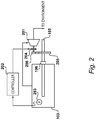
Figure 2 shows a way of implementing the electric machine ofFigure 1 ; and -
Figure 3 shows another way of implementing the electric machine ofFigure 1 . - A block diagram illustrating an embodiment is shown in
Figure 1 , in which an electric machine is shown generally at 101. - The
electric machine 101 comprises adepressurisation system 102. Thedepressurisation system 102 operates to depressurise acasing 103 of theelectric machine 101 below an external pressure of theenvironment 104 in which theelectric machine 101 is located. - The
casing 103 houses electromechanical components (not shown) which effect the conversion of electrical power into work upon ashaft 105, or vice versa depending upon the assigned role of theelectric machine 101, for example whether it is to operate as a motor or generator. It will be appreciated that the exact configuration of the electromechanical components within thecasing 103 will differ according to the type of the electric machine as implemented, and thus may include coils, magnets, brushes, springs, commutators, power electronics, etc. - As the shaft extends outside of the casing, a
seal 106 is provided to seal the casing around the shaft. Whilst theshaft 105 is shown extending out of only one end of the casing, it will be appreciated that the principles of the present invention may be extended to electric machines in which the shaft extends the full way through the casing, thus having what are commonly referred to as working and non-working ends. In such an implementation, anotherseal 106 would be provided to seal the casing around the two ends of the shaft. - As described previously, in one embodiment the
seal 106 comprises a labyrinth seal. Labyrinth seals are characterised by a series of annular orifices used to seal a region of high pressure from one of low pressure. When gas flows from the high pressure side to the low pressure side of the seal, turbulence is caused by each annulus of the seal. Whilst this serves to minimise leakage, it does not entirely prevent it. Thus, in this example, thedepressurisation system 102 operates to maintain the pressure in thecasing 103 despite any leakage fromenvironment 104 through the labyrinth seal and into thecasing 103. - In an alternative embodiment, the
seal 106 comprises a dry gas seal. Such seals feature zones between the stationary face of the casing and rotating face of the shaft, into which gas is pumped. When the pressure of gas in these zones exceeds the static pressure holding the faces together, the faces separate by a thin layer of gas. Dry gas seals are supplied gas at pressure via an inlet, and have an outlet for seal gas to be vented. As the zones are small, the pressure in them tends to be greater than that in theenvironment 104, and thus there is little leakage of gas fromenvironment 104 through theseal 106 and into thecasing 103 in such an implementation. - It will of course be appreciated that any appropriate type of seal or combination of seals may be used to prevent substantial ingress of air from the
environment 104 into thecasing 103. - It will be apparent that the degree of vacuum required within the
casing 103 is dependent upon, with respect to any two electrodes therein, the peak operational potential difference between them, and the distance between them. Paschen's law may therefore be used to obtain, given a peak operational voltage, the maximum permitted product of pressure and distance between electrodes to prevent electrical breakdown, and therefore arcing, corona, etc. - A practical approach to implementing the electric machine of
Figure 1 , is shown inFigure 2 . - In this example, the
depressurisation system 102 comprises avacuum pump 201 driven by theshaft 105. In the present embodiment, thevacuum pump 201 is a positive-displacement vacuum pump. In a specific embodiment, the positive-displacement pump is a rotary vane pump. However, it will be appreciated that the pump may be any other type of positive-displacement device such as a Roots blower. - In an alternative implementation, the vacuum pump is a centrifugal-type vacuum pump such as a radial inflow pump, or any other suitable type of vacuum pump. In addition, the vacuum pump may be multi-stage.
- In order to maintain the pressure in the
casing 103 at a level sufficient to prevent electrical breakdown, in the present example acontroller 202 and apressure sensor 203 within the casing are provided. Thepressure sensor 203 is configured to provide thecontroller 203 with a signal indicative of the pressure therein, which thecontroller 202 is configured to utilise to control operation of the vacuum pump by means of aclutch 204. In the present example, theclutch 204 is actuated by a solenoid (not shown) connected with thecontroller 202, but it will be appreciated that other arrangements are possible to achieve activation/deactivation of thevacuum pump 201. - In an example, the
controller 202 is an analog controller configured to implement a prescribed control loop. Alternatively, the controller may be a digital controller with software-defined logic to achieve the desired control over the pressure in thecasing 103. The controller in the latter case may form part of another sub-system in the wider installation theelectric machine 101 forms part of. - The control loop in the present example operates to compare the current pressure within the
casing 103 to a prescribed threshold, above which electrical breakdown may occur. If the current pressure is determined to be below the threshold, the vacuum pump is enabled (i.e. thecontroller 202 allows to evacuate the casing 103) by engaging theclutch 204. If the current pressure is determined to be above the threshold, the vacuum pump is disabled by disengaging the clutch 204 (i.e. thecontroller 202 prevents it from evacuating the casing 103). - In a specific embodiment, a degree of hysteresis is included in the control loop to prevent over-actuation of the
clutch 204 andvacuum pump 201. In this way, thevacuum pump 201 is only disabled once the pressure in thecasing 103 is below the threshold pressure, less a lag value. As gas enters thecasing 103, the pressure will rise and approach the threshold, leading to thevacuum pump 201 being enabled by thecontroller 202 to depressurise thecasing 103. Such a control loop may be implemented using a Schmitt trigger or similar, or as one or more conditional statements in a software implementation. - The
vacuum pump 201 is, in the present example, geared to theshaft 105 in order to drive the pump at the requisite angular rate to evacuate thecasing 103. In the present example, this is achieved by a combination of agear 205 on theshaft 105 meshed with apinion 206 to drive thevacuum pump 201 via the clutch 204. It will be appreciated that the gear ratio will be in practice be dependent upon a combination of the angular rate required for thevacuum pump 201, and the operational rate of theelectric machine 101. In a specific embodiment, the gear system used to connect the vacuum pump to the shaft is a magnetic gear. - In a further variation, the
vacuum pump 201 may instead be geared to the shaft using a variable transmission, possibly a variable magnetic gear. In this way, the clutch 204 may be omitted, and the vacuum pump's speed and therefore pressure ratio varied by thecontroller 202 to maintain the pressure in thecasing 103 at a fixed value, or within an acceptable defined range. - Gearing may be omitted, of course, if the
electric machine 101 is to operate at same angular rate as required by thevacuum pump 201. - Another approach to implementing the electric machine of
Figure 1 , is illustrated inFigure 3 . - In this example, the
depressurisation system 102 comprisesvacuum pump 201, but in an electrically-driven configuration in which it is driven by amotor 301. - In this embodiment the
motor 301 operates under the control ofcontroller 202 which, in a similar way as described previously with reference toFigure 2 , may either enable or disable it in response to the output ofpressure sensor 203 in thecasing 103. Alternatively, as described previously, thecontroller 202 may vary the speed of themotor 301 so as to maintain the pressure in thecasing 103 at a fixed value or within an acceptable defined range. - The
motor 301 in this example operates at a much lower voltage than the electromechanical components in thecasing 103. In this way, it is able to operate in low pressure environments such as may be encountered at aircraft cruise altitude without experiencing electrical breakdown, whereas breakdown could occur between the components in thecasing 103 without depressurisation due to the higher voltages therein. Of course, it will be understood that themotor 301 could, in an alternative embodiment, be itself depressurised should electrical breakdown be possible due to its specification and operating environment. - One benefit of using the arrangement shown in
Figure 3 is that, prior to starting theelectric machine 101, thecasing 103 may be depressurised by thevacuum pump 201 driven by themotor 301. This can be of particular advantage should theelectric machine 101 form part of an on-demand system in an aircraft in which it would not be running constantly. Further, it may be of advantage should theelectric machine 101 form part of a wider system that is only started and used in low-pressure environments, rather than being started at, say, sea level and transitioning to a higher altitude. - Lastly, it will be appreciated that the
electric machine 101 of the present invention and the principles it embodies may be used in any gaseous environment which, when combined with the specification of the electromechanical components within thecasing 104, is liable to cause electrical breakdown therein. This may be anticipated by application of Paschen's law. Thus, in terms of the parameters that may cause this, the possibility of electrical breakdown occurring may be ascribed to one or more of the external gas pressure within theenvironment 105, the peak voltages within thecasing 104, and/or the minimum distance between electrodes within thecasing 104. Thus, for example, theelectric machine 101 may indeed be used in applications at, say, standard temperature and pressure, if the peak voltage and minimum distance are such that electrical breakdown may still occur. - Various examples have been described, each of which feature various combinations of features. It will be appreciated by those skilled in the art that, except where clearly mutually exclusive, any of the features may be employed separately or in combination with any other features and the invention extends to and includes all combinations and sub-combinations of one or more features described herein.
Claims (15)
- An electric machine for use in an aircraft, comprising:a casing containing electromechanical components;a shaft which extends outside of the casing;a seal to seal the casing around the shaft; anda depressurisation system configured to depressurise the casing below an external gas pressure to prevent electrical breakdown within gas in the casing.
- The electric machine of claim 1, in which the seal comprises a labyrinth seal.
- The electric machine of claim 1 or claim 2, in which the seal comprises a dry gas seal.
- The electric machine of any one of claims 1 to 3, in which the depressurisation system comprises a vacuum pump.
- The electric machine of claim 4, in which the vacuum pump is a positive-displacement vacuum pump
- The electric machine of claim 4 or claim 5, in which the vacuum pump is driven by the shaft of the electric machine.
- The electric machine of claim 6, in which the vacuum pump is geared to the shaft of the electric machine.
- The electric machine of claim 7, in which the vacuum pump is geared to the shaft of the electric machine by a magnetic gear.
- The electric machine of any of claims 6 to 8, in which the connection between the vacuum pump and the shaft is clutched.
- The electric machine of claim 4 or claim 5, in which the vacuum pump is driven electrically.
- The electric machine of any one of claims 4 to 10, in which the depressurisation system comprises:a pressure sensor configured to output an indication of the gas pressure within the casing; anda controller configured control the vacuum pump in response to the output of the pressure sensor.
- The electric machine of claim 11, in which the controller is configured to:determine that the pressure within the casing has risen above a threshold, and allow the vacuum pump to evacuate the casing;determine that the pressure within the casing has dropped below the threshold, and prevent the vacuum pump from evacuating the casing.
- The electric machine of claim 11, in which the controller is configured to vary the speed of the vacuum pump to maintain the pressure within the casing below the external gas pressure.
- An aircraft including an electric machine according to any one of claims 1 to 13.
- The aircraft of claim 14, in which the electric machine is located within an engine of the aircraft.
Applications Claiming Priority (1)
| Application Number | Priority Date | Filing Date | Title |
|---|---|---|---|
| GBGB1708297.5A GB201708297D0 (en) | 2017-05-24 | 2017-05-24 | Preventing electrical breakdown |
Publications (2)
| Publication Number | Publication Date |
|---|---|
| EP3421734A1 true EP3421734A1 (en) | 2019-01-02 |
| EP3421734B1 EP3421734B1 (en) | 2020-09-02 |
Family
ID=59220713
Family Applications (2)
| Application Number | Title | Priority Date | Filing Date |
|---|---|---|---|
| EP18170240.8A Active EP3421735B1 (en) | 2017-05-24 | 2018-05-01 | Preventing electrical breakdown of an aircraft propulsor |
| EP18170239.0A Active EP3421734B1 (en) | 2017-05-24 | 2018-05-01 | Preventing electrical breakdown |
Family Applications Before (1)
| Application Number | Title | Priority Date | Filing Date |
|---|---|---|---|
| EP18170240.8A Active EP3421735B1 (en) | 2017-05-24 | 2018-05-01 | Preventing electrical breakdown of an aircraft propulsor |
Country Status (4)
| Country | Link |
|---|---|
| US (2) | US11518530B2 (en) |
| EP (2) | EP3421735B1 (en) |
| CN (1) | CN108933492A (en) |
| GB (1) | GB201708297D0 (en) |
Cited By (4)
| Publication number | Priority date | Publication date | Assignee | Title |
|---|---|---|---|---|
| WO2021073772A1 (en) * | 2019-10-15 | 2021-04-22 | Eaton Intelligent Power Limited | Internally pressurized electric motor |
| FR3105299A1 (en) * | 2019-12-19 | 2021-06-25 | Safran | Power electronics device for an aircraft |
| WO2023067336A1 (en) * | 2021-10-19 | 2023-04-27 | John Crane Uk Limited | Pumping seal for rotating machines |
| US11870320B2 (en) | 2021-10-19 | 2024-01-09 | John Crane Uk Limited | Pumping seal for rotating machines |
Families Citing this family (2)
| Publication number | Priority date | Publication date | Assignee | Title |
|---|---|---|---|---|
| DE102022203746A1 (en) | 2022-04-13 | 2023-10-19 | Rolls-Royce Deutschland Ltd & Co Kg | Propulsion device for an aircraft |
| CN118067396B (en) * | 2024-04-19 | 2024-06-28 | 哈尔滨工业大学 | In-orbit imaging monitoring method for plasma thruster ignition |
Citations (5)
| Publication number | Priority date | Publication date | Assignee | Title |
|---|---|---|---|---|
| US20060254255A1 (en) * | 2005-01-25 | 2006-11-16 | Japan Aerospace Exploration Agency | Aircraft propulsion system |
| US20150318760A1 (en) * | 2014-01-10 | 2015-11-05 | Temporal Power Ltd. | High-Voltage Flywheel Energy Storage System |
| EP3093235A1 (en) * | 2015-05-13 | 2016-11-16 | Rolls-Royce plc | Aircraft |
| US20160355272A1 (en) * | 2015-05-13 | 2016-12-08 | Rolls-Royce Plc | Aircraft propulsion system |
| EP3159546A1 (en) * | 2015-10-21 | 2017-04-26 | Rolls-Royce PLC | Pump |
Family Cites Families (25)
| Publication number | Priority date | Publication date | Assignee | Title |
|---|---|---|---|---|
| GB583798A (en) | 1942-07-24 | 1946-12-31 | Simms Motor Units Ltd | Improvements in or relating to magnetos |
| GB718200A (en) | 1952-01-25 | 1954-11-10 | English Electric Co Ltd | Improvements relating to cooling systems for dynamo-electric machines of aircraft |
| US3681628A (en) * | 1970-09-14 | 1972-08-01 | Christoslaw Krastchew | Cooling arrangement for a dynamoelectric machine |
| US4662826A (en) * | 1984-04-20 | 1987-05-05 | Tokico Ltd. | Vacuum pump system including serially connected rotary and reciprocating vacuum pumps |
| US5977645A (en) | 1997-06-30 | 1999-11-02 | Sundstrand Corporation | Aircraft secondary power system |
| US6570389B2 (en) | 2001-06-15 | 2003-05-27 | International Business Machines Corporation | Prevention of arcing in power supplies |
| US6733240B2 (en) | 2001-07-18 | 2004-05-11 | General Electric Company | Serrated fan blade |
| JP2005209791A (en) * | 2004-01-21 | 2005-08-04 | Canon Inc | Electric operation device in vacuum |
| GB0417847D0 (en) * | 2004-08-11 | 2004-09-15 | Rolls Royce Plc | Bearing assembly |
| WO2006073634A2 (en) * | 2004-12-02 | 2006-07-13 | Richard H Lugg | Vtol aircraft with forward-swept fixed wing |
| JP4285562B2 (en) | 2007-05-28 | 2009-06-24 | トヨタ自動車株式会社 | MOBILE BODY MOTOR DEVICE AND MOBILE BODY HAVING SAME |
| CN107084036B (en) * | 2008-04-16 | 2019-10-22 | 米提亚·维克托·辛德克斯 | Reciprocating machines and other devices |
| GB0817046D0 (en) * | 2008-09-18 | 2008-10-22 | Rolls Royce Plc | Magnectic Gear Arrangement |
| US8099944B2 (en) | 2008-10-08 | 2012-01-24 | The Invention Science Fund I, Llc | Hybrid propulsive engine including at least one independently rotatable propeller/fan |
| US7938874B2 (en) | 2008-12-05 | 2011-05-10 | Dresser-Rand Company | Driven separator for gas seal panels |
| SG172127A1 (en) | 2008-12-15 | 2011-07-28 | Flowserve Man Co | Seal leakage gas recovery system |
| CN201428517Y (en) | 2009-06-03 | 2010-03-24 | 中国航空动力机械研究所 | Auxiliary power device |
| IT1397059B1 (en) | 2009-11-23 | 2012-12-28 | Nuovo Pignone Spa | SEAL SYSTEM FOR DRY GAS, LOW EMISSION FOR COMPRESSORS |
| EP2413483A1 (en) * | 2010-07-30 | 2012-02-01 | Siemens Aktiengesellschaft | Electric drive device for an aircraft |
| JP5231611B2 (en) | 2010-10-22 | 2013-07-10 | 株式会社神戸製鋼所 | Compressor |
| AU2012229589B2 (en) | 2011-03-15 | 2017-09-14 | Aker Solutions As | Subsea pressure booster |
| DK201270604A (en) * | 2011-12-07 | 2013-06-08 | Envision Energy Denmark Aps | Wind Turbine with sealed off stator chamber |
| JP6189890B2 (en) * | 2015-03-25 | 2017-08-30 | ファナック株式会社 | Blower equipped with a structure that suppresses damage to the shaft seal |
| US10308365B2 (en) * | 2015-10-12 | 2019-06-04 | Codrin-Gruie (CG) Cantemir | Fully integrated hybrid electric jet engine |
| JP6181138B2 (en) | 2015-11-18 | 2017-08-16 | 8 リバーズ キャピタル,エルエルシー | Shaft seal device and power generation system |
-
2017
- 2017-05-24 GB GBGB1708297.5A patent/GB201708297D0/en not_active Ceased
-
2018
- 2018-05-01 EP EP18170240.8A patent/EP3421735B1/en active Active
- 2018-05-01 EP EP18170239.0A patent/EP3421734B1/en active Active
- 2018-05-21 US US15/984,557 patent/US11518530B2/en active Active
- 2018-05-21 US US15/984,555 patent/US11572182B2/en active Active
- 2018-05-24 CN CN201810507921.5A patent/CN108933492A/en active Pending
Patent Citations (5)
| Publication number | Priority date | Publication date | Assignee | Title |
|---|---|---|---|---|
| US20060254255A1 (en) * | 2005-01-25 | 2006-11-16 | Japan Aerospace Exploration Agency | Aircraft propulsion system |
| US20150318760A1 (en) * | 2014-01-10 | 2015-11-05 | Temporal Power Ltd. | High-Voltage Flywheel Energy Storage System |
| EP3093235A1 (en) * | 2015-05-13 | 2016-11-16 | Rolls-Royce plc | Aircraft |
| US20160355272A1 (en) * | 2015-05-13 | 2016-12-08 | Rolls-Royce Plc | Aircraft propulsion system |
| EP3159546A1 (en) * | 2015-10-21 | 2017-04-26 | Rolls-Royce PLC | Pump |
Cited By (5)
| Publication number | Priority date | Publication date | Assignee | Title |
|---|---|---|---|---|
| WO2021073772A1 (en) * | 2019-10-15 | 2021-04-22 | Eaton Intelligent Power Limited | Internally pressurized electric motor |
| US12500482B2 (en) | 2019-10-15 | 2025-12-16 | Eaton Intelligent Power Limited | Internally pressurized electric motor |
| FR3105299A1 (en) * | 2019-12-19 | 2021-06-25 | Safran | Power electronics device for an aircraft |
| WO2023067336A1 (en) * | 2021-10-19 | 2023-04-27 | John Crane Uk Limited | Pumping seal for rotating machines |
| US11870320B2 (en) | 2021-10-19 | 2024-01-09 | John Crane Uk Limited | Pumping seal for rotating machines |
Also Published As
| Publication number | Publication date |
|---|---|
| US11572182B2 (en) | 2023-02-07 |
| US20180339782A1 (en) | 2018-11-29 |
| EP3421734B1 (en) | 2020-09-02 |
| GB201708297D0 (en) | 2017-07-05 |
| EP3421735A1 (en) | 2019-01-02 |
| US20180342923A1 (en) | 2018-11-29 |
| CN108933492A (en) | 2018-12-04 |
| US11518530B2 (en) | 2022-12-06 |
| EP3421735B1 (en) | 2020-09-09 |
Similar Documents
| Publication | Publication Date | Title |
|---|---|---|
| EP3421734B1 (en) | Preventing electrical breakdown | |
| US11303181B2 (en) | Preventing electrical breakdown | |
| US10669950B2 (en) | Engine architecture using electric machine | |
| JP6130689B2 (en) | Device for extracting input power from a low-pressure spool of a turbine engine | |
| CA2913526C (en) | Jet engine assembly and method for generating electricity | |
| US11421554B2 (en) | Gas turbine engine generator oil pump | |
| US8823334B2 (en) | Method for starting an electric motor | |
| US10690000B1 (en) | Gas turbine engine and method of operating same | |
| JP2024133183A (en) | Electrical machine including a device for forcibly demagnetizing a permanent magnet | |
| US10541634B2 (en) | Generator arrangements and methods of controlling generator arrangements | |
| US10797574B2 (en) | Electrical machine | |
| US20190211702A1 (en) | A device for controlling inlet guide vanes by means of a multilayer piezoelectric actuator | |
| US10972030B2 (en) | Multi-stage synchronous generator | |
| WO1997000201A1 (en) | Thermal de-icing system for a rotating element | |
| US2382908A (en) | Electric protective system | |
| CA3156955C (en) | Oil and fuel control system for an engine and method for controlling oil and fuel in an engine |
Legal Events
| Date | Code | Title | Description |
|---|---|---|---|
| PUAI | Public reference made under article 153(3) epc to a published international application that has entered the european phase |
Free format text: ORIGINAL CODE: 0009012 |
|
| STAA | Information on the status of an ep patent application or granted ep patent |
Free format text: STATUS: THE APPLICATION HAS BEEN PUBLISHED |
|
| AK | Designated contracting states |
Kind code of ref document: A1 Designated state(s): AL AT BE BG CH CY CZ DE DK EE ES FI FR GB GR HR HU IE IS IT LI LT LU LV MC MK MT NL NO PL PT RO RS SE SI SK SM TR |
|
| AX | Request for extension of the european patent |
Extension state: BA ME |
|
| STAA | Information on the status of an ep patent application or granted ep patent |
Free format text: STATUS: REQUEST FOR EXAMINATION WAS MADE |
|
| 17P | Request for examination filed |
Effective date: 20190206 |
|
| RBV | Designated contracting states (corrected) |
Designated state(s): AL AT BE BG CH CY CZ DE DK EE ES FI FR GB GR HR HU IE IS IT LI LT LU LV MC MK MT NL NO PL PT RO RS SE SI SK SM TR |
|
| STAA | Information on the status of an ep patent application or granted ep patent |
Free format text: STATUS: EXAMINATION IS IN PROGRESS |
|
| 17Q | First examination report despatched |
Effective date: 20190725 |
|
| RAP1 | Party data changed (applicant data changed or rights of an application transferred) |
Owner name: ROLLS-ROYCE PLC |
|
| RIC1 | Information provided on ipc code assigned before grant |
Ipc: B64D 33/00 20060101ALI20200327BHEP Ipc: B64D 45/02 20060101ALI20200327BHEP Ipc: B64D 27/24 20060101ALI20200327BHEP Ipc: F01D 15/10 20060101AFI20200327BHEP Ipc: B64D 37/32 20060101ALI20200327BHEP |
|
| GRAP | Despatch of communication of intention to grant a patent |
Free format text: ORIGINAL CODE: EPIDOSNIGR1 |
|
| STAA | Information on the status of an ep patent application or granted ep patent |
Free format text: STATUS: GRANT OF PATENT IS INTENDED |
|
| INTG | Intention to grant announced |
Effective date: 20200511 |
|
| GRAS | Grant fee paid |
Free format text: ORIGINAL CODE: EPIDOSNIGR3 |
|
| GRAA | (expected) grant |
Free format text: ORIGINAL CODE: 0009210 |
|
| STAA | Information on the status of an ep patent application or granted ep patent |
Free format text: STATUS: THE PATENT HAS BEEN GRANTED |
|
| AK | Designated contracting states |
Kind code of ref document: B1 Designated state(s): AL AT BE BG CH CY CZ DE DK EE ES FI FR GB GR HR HU IE IS IT LI LT LU LV MC MK MT NL NO PL PT RO RS SE SI SK SM TR |
|
| REG | Reference to a national code |
Ref country code: GB Ref legal event code: FG4D |
|
| REG | Reference to a national code |
Ref country code: AT Ref legal event code: REF Ref document number: 1309029 Country of ref document: AT Kind code of ref document: T Effective date: 20200915 Ref country code: CH Ref legal event code: EP |
|
| REG | Reference to a national code |
Ref country code: DE Ref legal event code: R096 Ref document number: 602018007375 Country of ref document: DE |
|
| REG | Reference to a national code |
Ref country code: IE Ref legal event code: FG4D |
|
| REG | Reference to a national code |
Ref country code: LT Ref legal event code: MG4D |
|
| PG25 | Lapsed in a contracting state [announced via postgrant information from national office to epo] |
Ref country code: LT Free format text: LAPSE BECAUSE OF FAILURE TO SUBMIT A TRANSLATION OF THE DESCRIPTION OR TO PAY THE FEE WITHIN THE PRESCRIBED TIME-LIMIT Effective date: 20200902 Ref country code: HR Free format text: LAPSE BECAUSE OF FAILURE TO SUBMIT A TRANSLATION OF THE DESCRIPTION OR TO PAY THE FEE WITHIN THE PRESCRIBED TIME-LIMIT Effective date: 20200902 Ref country code: BG Free format text: LAPSE BECAUSE OF FAILURE TO SUBMIT A TRANSLATION OF THE DESCRIPTION OR TO PAY THE FEE WITHIN THE PRESCRIBED TIME-LIMIT Effective date: 20201202 Ref country code: SE Free format text: LAPSE BECAUSE OF FAILURE TO SUBMIT A TRANSLATION OF THE DESCRIPTION OR TO PAY THE FEE WITHIN THE PRESCRIBED TIME-LIMIT Effective date: 20200902 Ref country code: FI Free format text: LAPSE BECAUSE OF FAILURE TO SUBMIT A TRANSLATION OF THE DESCRIPTION OR TO PAY THE FEE WITHIN THE PRESCRIBED TIME-LIMIT Effective date: 20200902 Ref country code: NO Free format text: LAPSE BECAUSE OF FAILURE TO SUBMIT A TRANSLATION OF THE DESCRIPTION OR TO PAY THE FEE WITHIN THE PRESCRIBED TIME-LIMIT Effective date: 20201202 Ref country code: GR Free format text: LAPSE BECAUSE OF FAILURE TO SUBMIT A TRANSLATION OF THE DESCRIPTION OR TO PAY THE FEE WITHIN THE PRESCRIBED TIME-LIMIT Effective date: 20201203 |
|
| REG | Reference to a national code |
Ref country code: NL Ref legal event code: MP Effective date: 20200902 |
|
| REG | Reference to a national code |
Ref country code: AT Ref legal event code: MK05 Ref document number: 1309029 Country of ref document: AT Kind code of ref document: T Effective date: 20200902 |
|
| PG25 | Lapsed in a contracting state [announced via postgrant information from national office to epo] |
Ref country code: LV Free format text: LAPSE BECAUSE OF FAILURE TO SUBMIT A TRANSLATION OF THE DESCRIPTION OR TO PAY THE FEE WITHIN THE PRESCRIBED TIME-LIMIT Effective date: 20200902 Ref country code: RS Free format text: LAPSE BECAUSE OF FAILURE TO SUBMIT A TRANSLATION OF THE DESCRIPTION OR TO PAY THE FEE WITHIN THE PRESCRIBED TIME-LIMIT Effective date: 20200902 Ref country code: PL Free format text: LAPSE BECAUSE OF FAILURE TO SUBMIT A TRANSLATION OF THE DESCRIPTION OR TO PAY THE FEE WITHIN THE PRESCRIBED TIME-LIMIT Effective date: 20200902 |
|
| PG25 | Lapsed in a contracting state [announced via postgrant information from national office to epo] |
Ref country code: EE Free format text: LAPSE BECAUSE OF FAILURE TO SUBMIT A TRANSLATION OF THE DESCRIPTION OR TO PAY THE FEE WITHIN THE PRESCRIBED TIME-LIMIT Effective date: 20200902 Ref country code: CZ Free format text: LAPSE BECAUSE OF FAILURE TO SUBMIT A TRANSLATION OF THE DESCRIPTION OR TO PAY THE FEE WITHIN THE PRESCRIBED TIME-LIMIT Effective date: 20200902 Ref country code: RO Free format text: LAPSE BECAUSE OF FAILURE TO SUBMIT A TRANSLATION OF THE DESCRIPTION OR TO PAY THE FEE WITHIN THE PRESCRIBED TIME-LIMIT Effective date: 20200902 Ref country code: PT Free format text: LAPSE BECAUSE OF FAILURE TO SUBMIT A TRANSLATION OF THE DESCRIPTION OR TO PAY THE FEE WITHIN THE PRESCRIBED TIME-LIMIT Effective date: 20210104 Ref country code: SM Free format text: LAPSE BECAUSE OF FAILURE TO SUBMIT A TRANSLATION OF THE DESCRIPTION OR TO PAY THE FEE WITHIN THE PRESCRIBED TIME-LIMIT Effective date: 20200902 |
|
| PG25 | Lapsed in a contracting state [announced via postgrant information from national office to epo] |
Ref country code: IS Free format text: LAPSE BECAUSE OF FAILURE TO SUBMIT A TRANSLATION OF THE DESCRIPTION OR TO PAY THE FEE WITHIN THE PRESCRIBED TIME-LIMIT Effective date: 20210102 Ref country code: AL Free format text: LAPSE BECAUSE OF FAILURE TO SUBMIT A TRANSLATION OF THE DESCRIPTION OR TO PAY THE FEE WITHIN THE PRESCRIBED TIME-LIMIT Effective date: 20200902 Ref country code: AT Free format text: LAPSE BECAUSE OF FAILURE TO SUBMIT A TRANSLATION OF THE DESCRIPTION OR TO PAY THE FEE WITHIN THE PRESCRIBED TIME-LIMIT Effective date: 20200902 Ref country code: ES Free format text: LAPSE BECAUSE OF FAILURE TO SUBMIT A TRANSLATION OF THE DESCRIPTION OR TO PAY THE FEE WITHIN THE PRESCRIBED TIME-LIMIT Effective date: 20200902 |
|
| REG | Reference to a national code |
Ref country code: DE Ref legal event code: R097 Ref document number: 602018007375 Country of ref document: DE |
|
| PG25 | Lapsed in a contracting state [announced via postgrant information from national office to epo] |
Ref country code: SK Free format text: LAPSE BECAUSE OF FAILURE TO SUBMIT A TRANSLATION OF THE DESCRIPTION OR TO PAY THE FEE WITHIN THE PRESCRIBED TIME-LIMIT Effective date: 20200902 |
|
| PLBE | No opposition filed within time limit |
Free format text: ORIGINAL CODE: 0009261 |
|
| STAA | Information on the status of an ep patent application or granted ep patent |
Free format text: STATUS: NO OPPOSITION FILED WITHIN TIME LIMIT |
|
| 26N | No opposition filed |
Effective date: 20210603 |
|
| PG25 | Lapsed in a contracting state [announced via postgrant information from national office to epo] |
Ref country code: DK Free format text: LAPSE BECAUSE OF FAILURE TO SUBMIT A TRANSLATION OF THE DESCRIPTION OR TO PAY THE FEE WITHIN THE PRESCRIBED TIME-LIMIT Effective date: 20200902 Ref country code: SI Free format text: LAPSE BECAUSE OF FAILURE TO SUBMIT A TRANSLATION OF THE DESCRIPTION OR TO PAY THE FEE WITHIN THE PRESCRIBED TIME-LIMIT Effective date: 20200902 |
|
| PG25 | Lapsed in a contracting state [announced via postgrant information from national office to epo] |
Ref country code: IT Free format text: LAPSE BECAUSE OF FAILURE TO SUBMIT A TRANSLATION OF THE DESCRIPTION OR TO PAY THE FEE WITHIN THE PRESCRIBED TIME-LIMIT Effective date: 20200902 |
|
| REG | Reference to a national code |
Ref country code: CH Ref legal event code: PL |
|
| PG25 | Lapsed in a contracting state [announced via postgrant information from national office to epo] |
Ref country code: MC Free format text: LAPSE BECAUSE OF FAILURE TO SUBMIT A TRANSLATION OF THE DESCRIPTION OR TO PAY THE FEE WITHIN THE PRESCRIBED TIME-LIMIT Effective date: 20200902 Ref country code: LU Free format text: LAPSE BECAUSE OF NON-PAYMENT OF DUE FEES Effective date: 20210501 Ref country code: LI Free format text: LAPSE BECAUSE OF NON-PAYMENT OF DUE FEES Effective date: 20210531 Ref country code: CH Free format text: LAPSE BECAUSE OF NON-PAYMENT OF DUE FEES Effective date: 20210531 |
|
| REG | Reference to a national code |
Ref country code: BE Ref legal event code: MM Effective date: 20210531 |
|
| PG25 | Lapsed in a contracting state [announced via postgrant information from national office to epo] |
Ref country code: IE Free format text: LAPSE BECAUSE OF NON-PAYMENT OF DUE FEES Effective date: 20210501 |
|
| PG25 | Lapsed in a contracting state [announced via postgrant information from national office to epo] |
Ref country code: BE Free format text: LAPSE BECAUSE OF NON-PAYMENT OF DUE FEES Effective date: 20210531 |
|
| PG25 | Lapsed in a contracting state [announced via postgrant information from national office to epo] |
Ref country code: NL Free format text: LAPSE BECAUSE OF NON-PAYMENT OF DUE FEES Effective date: 20200923 Ref country code: CY Free format text: LAPSE BECAUSE OF FAILURE TO SUBMIT A TRANSLATION OF THE DESCRIPTION OR TO PAY THE FEE WITHIN THE PRESCRIBED TIME-LIMIT Effective date: 20200902 |
|
| P01 | Opt-out of the competence of the unified patent court (upc) registered |
Effective date: 20230528 |
|
| PG25 | Lapsed in a contracting state [announced via postgrant information from national office to epo] |
Ref country code: HU Free format text: LAPSE BECAUSE OF FAILURE TO SUBMIT A TRANSLATION OF THE DESCRIPTION OR TO PAY THE FEE WITHIN THE PRESCRIBED TIME-LIMIT; INVALID AB INITIO Effective date: 20180501 |
|
| PG25 | Lapsed in a contracting state [announced via postgrant information from national office to epo] |
Ref country code: MK Free format text: LAPSE BECAUSE OF FAILURE TO SUBMIT A TRANSLATION OF THE DESCRIPTION OR TO PAY THE FEE WITHIN THE PRESCRIBED TIME-LIMIT Effective date: 20200902 |
|
| PG25 | Lapsed in a contracting state [announced via postgrant information from national office to epo] |
Ref country code: MT Free format text: LAPSE BECAUSE OF FAILURE TO SUBMIT A TRANSLATION OF THE DESCRIPTION OR TO PAY THE FEE WITHIN THE PRESCRIBED TIME-LIMIT Effective date: 20200902 |
|
| PGFP | Annual fee paid to national office [announced via postgrant information from national office to epo] |
Ref country code: DE Payment date: 20250528 Year of fee payment: 8 |
|
| PGFP | Annual fee paid to national office [announced via postgrant information from national office to epo] |
Ref country code: FR Payment date: 20250526 Year of fee payment: 8 |
|
| PG25 | Lapsed in a contracting state [announced via postgrant information from national office to epo] |
Ref country code: TR Free format text: LAPSE BECAUSE OF FAILURE TO SUBMIT A TRANSLATION OF THE DESCRIPTION OR TO PAY THE FEE WITHIN THE PRESCRIBED TIME-LIMIT Effective date: 20200902 |
|
| PGFP | Annual fee paid to national office [announced via postgrant information from national office to epo] |
Ref country code: GB Payment date: 20260313 Year of fee payment: 9 |