EP3421373A1 - Rotating devices for mitigation of adverse flow conditions in an ultra-short nacelle inlet - Google Patents
Rotating devices for mitigation of adverse flow conditions in an ultra-short nacelle inlet Download PDFInfo
- Publication number
- EP3421373A1 EP3421373A1 EP18179862.0A EP18179862A EP3421373A1 EP 3421373 A1 EP3421373 A1 EP 3421373A1 EP 18179862 A EP18179862 A EP 18179862A EP 3421373 A1 EP3421373 A1 EP 3421373A1
- Authority
- EP
- European Patent Office
- Prior art keywords
- flow control
- inlet
- nacelle
- control devices
- control system
- Prior art date
- Legal status (The legal status is an assumption and is not a legal conclusion. Google has not performed a legal analysis and makes no representation as to the accuracy of the status listed.)
- Granted
Links
Images





Classifications
-
- F—MECHANICAL ENGINEERING; LIGHTING; HEATING; WEAPONS; BLASTING
- F02—COMBUSTION ENGINES; HOT-GAS OR COMBUSTION-PRODUCT ENGINE PLANTS
- F02C—GAS-TURBINE PLANTS; AIR INTAKES FOR JET-PROPULSION PLANTS; CONTROLLING FUEL SUPPLY IN AIR-BREATHING JET-PROPULSION PLANTS
- F02C7/00—Features, components parts, details or accessories, not provided for in, or of interest apart form groups F02C1/00 - F02C6/00; Air intakes for jet-propulsion plants
- F02C7/04—Air intakes for gas-turbine plants or jet-propulsion plants
- F02C7/042—Air intakes for gas-turbine plants or jet-propulsion plants having variable geometry
-
- B—PERFORMING OPERATIONS; TRANSPORTING
- B64—AIRCRAFT; AVIATION; COSMONAUTICS
- B64D—EQUIPMENT FOR FITTING IN OR TO AIRCRAFT; FLIGHT SUITS; PARACHUTES; ARRANGEMENT OR MOUNTING OF POWER PLANTS OR PROPULSION TRANSMISSIONS IN AIRCRAFT
- B64D27/00—Arrangement or mounting of power plants in aircraft; Aircraft characterised by the type or position of power plants
- B64D27/02—Aircraft characterised by the type or position of power plants
- B64D27/16—Aircraft characterised by the type or position of power plants of jet type
- B64D27/18—Aircraft characterised by the type or position of power plants of jet type within, or attached to, wings
-
- B—PERFORMING OPERATIONS; TRANSPORTING
- B64—AIRCRAFT; AVIATION; COSMONAUTICS
- B64D—EQUIPMENT FOR FITTING IN OR TO AIRCRAFT; FLIGHT SUITS; PARACHUTES; ARRANGEMENT OR MOUNTING OF POWER PLANTS OR PROPULSION TRANSMISSIONS IN AIRCRAFT
- B64D29/00—Power-plant nacelles, fairings or cowlings
- B64D29/06—Attaching of nacelles, fairings or cowlings
-
- B—PERFORMING OPERATIONS; TRANSPORTING
- B64—AIRCRAFT; AVIATION; COSMONAUTICS
- B64D—EQUIPMENT FOR FITTING IN OR TO AIRCRAFT; FLIGHT SUITS; PARACHUTES; ARRANGEMENT OR MOUNTING OF POWER PLANTS OR PROPULSION TRANSMISSIONS IN AIRCRAFT
- B64D33/00—Arrangement in aircraft of power plant parts or auxiliaries not otherwise provided for
- B64D33/02—Arrangement in aircraft of power plant parts or auxiliaries not otherwise provided for of combustion air intakes
-
- F—MECHANICAL ENGINEERING; LIGHTING; HEATING; WEAPONS; BLASTING
- F02—COMBUSTION ENGINES; HOT-GAS OR COMBUSTION-PRODUCT ENGINE PLANTS
- F02C—GAS-TURBINE PLANTS; AIR INTAKES FOR JET-PROPULSION PLANTS; CONTROLLING FUEL SUPPLY IN AIR-BREATHING JET-PROPULSION PLANTS
- F02C7/00—Features, components parts, details or accessories, not provided for in, or of interest apart form groups F02C1/00 - F02C6/00; Air intakes for jet-propulsion plants
- F02C7/04—Air intakes for gas-turbine plants or jet-propulsion plants
- F02C7/045—Air intakes for gas-turbine plants or jet-propulsion plants having provisions for noise suppression
-
- F—MECHANICAL ENGINEERING; LIGHTING; HEATING; WEAPONS; BLASTING
- F02—COMBUSTION ENGINES; HOT-GAS OR COMBUSTION-PRODUCT ENGINE PLANTS
- F02C—GAS-TURBINE PLANTS; AIR INTAKES FOR JET-PROPULSION PLANTS; CONTROLLING FUEL SUPPLY IN AIR-BREATHING JET-PROPULSION PLANTS
- F02C7/00—Features, components parts, details or accessories, not provided for in, or of interest apart form groups F02C1/00 - F02C6/00; Air intakes for jet-propulsion plants
- F02C7/04—Air intakes for gas-turbine plants or jet-propulsion plants
- F02C7/057—Control or regulation
-
- B—PERFORMING OPERATIONS; TRANSPORTING
- B64—AIRCRAFT; AVIATION; COSMONAUTICS
- B64D—EQUIPMENT FOR FITTING IN OR TO AIRCRAFT; FLIGHT SUITS; PARACHUTES; ARRANGEMENT OR MOUNTING OF POWER PLANTS OR PROPULSION TRANSMISSIONS IN AIRCRAFT
- B64D33/00—Arrangement in aircraft of power plant parts or auxiliaries not otherwise provided for
- B64D33/02—Arrangement in aircraft of power plant parts or auxiliaries not otherwise provided for of combustion air intakes
- B64D2033/0226—Arrangement in aircraft of power plant parts or auxiliaries not otherwise provided for of combustion air intakes comprising boundary layer control means
-
- B—PERFORMING OPERATIONS; TRANSPORTING
- B64—AIRCRAFT; AVIATION; COSMONAUTICS
- B64D—EQUIPMENT FOR FITTING IN OR TO AIRCRAFT; FLIGHT SUITS; PARACHUTES; ARRANGEMENT OR MOUNTING OF POWER PLANTS OR PROPULSION TRANSMISSIONS IN AIRCRAFT
- B64D33/00—Arrangement in aircraft of power plant parts or auxiliaries not otherwise provided for
- B64D33/02—Arrangement in aircraft of power plant parts or auxiliaries not otherwise provided for of combustion air intakes
- B64D2033/0266—Arrangement in aircraft of power plant parts or auxiliaries not otherwise provided for of combustion air intakes specially adapted for particular type of power plants
- B64D2033/0286—Arrangement in aircraft of power plant parts or auxiliaries not otherwise provided for of combustion air intakes specially adapted for particular type of power plants for turbofan engines
-
- F—MECHANICAL ENGINEERING; LIGHTING; HEATING; WEAPONS; BLASTING
- F05—INDEXING SCHEMES RELATING TO ENGINES OR PUMPS IN VARIOUS SUBCLASSES OF CLASSES F01-F04
- F05D—INDEXING SCHEME FOR ASPECTS RELATING TO NON-POSITIVE-DISPLACEMENT MACHINES OR ENGINES, GAS-TURBINES OR JET-PROPULSION PLANTS
- F05D2220/00—Application
- F05D2220/30—Application in turbines
- F05D2220/32—Application in turbines in gas turbines
- F05D2220/323—Application in turbines in gas turbines for aircraft propulsion, e.g. jet engines
-
- F—MECHANICAL ENGINEERING; LIGHTING; HEATING; WEAPONS; BLASTING
- F05—INDEXING SCHEMES RELATING TO ENGINES OR PUMPS IN VARIOUS SUBCLASSES OF CLASSES F01-F04
- F05D—INDEXING SCHEME FOR ASPECTS RELATING TO NON-POSITIVE-DISPLACEMENT MACHINES OR ENGINES, GAS-TURBINES OR JET-PROPULSION PLANTS
- F05D2260/00—Function
- F05D2260/50—Kinematic linkage, i.e. transmission of position
- F05D2260/57—Kinematic linkage, i.e. transmission of position using servos, independent actuators, etc.
Definitions
- Exemplary embodiments of the disclosure relate generally to aerodynamic flow control for turbofan aircraft nacelles and more particularly to flow control devices on the leading lip of ultra-short nacelles.
- Turbofan engines are widely employed for large commercial aircraft. As engines become larger and fans become wider, nacelles housing the fans must become shorter to achieve lower fuel burns (lower drag and weight). However, shorter nacelles, especially the resulting shorter inlets means that at adverse conditions such as high angles of attack (takeoff and over-rotation) or crosswind conditions the flow is more likely to separate behind the leading edge of the short inlet.
- the short inlet's smaller leading edge radius, and other features makes it more difficult for flow to stay attached when airflow entering the engine must turn before heading in a direction approximately normal to the fan-face. If the flow separates at the leading-edge of the nacelle, the resulting flow distortion (total pressure decrease) at the fan-face is undesirable.
- the separated flow may reduce performance, increase noise, and require heavier support structure to mitigate aerodynamically induced vibration.
- Existing solutions include simply making the inlet longer and adding a thicker lip. Alternatively blow-in doors used earlier nacelle designs may be employed. However, making the inlet longer is not an optimal solution with very large engine diameters as it reduces effectiveness of the larger engine by creating excess drag and weight. Blow-in doors increase emitted noise from aircraft operations and are structurally complex. It is therefore desirable to provide alternative solutions for inlet flow control which overcome the constraints of prior art solutions and provide improved performance.
- a flow control system on an aircraft engine nacelle incorporates a plurality of flow control devices each having a body.
- An additional plurality of actuators is coupled to a trailing edge of the body of an associated one of the flow control devices.
- the actuator rotates the body about a leading edge of an inlet of a nacelle from a retracted position to an extended position.
- the embodiments disclosed provide a method for inlet flow control on an ultra-short turbofan engine nacelle by extending a plurality of flow control devices on each engine nacelle in at least lower quadrants of an inlet circumference accommodating a high angle of attack of the nacelle.
- the exemplary embodiments described herein provide flow control devices for adverse flow conditions in an ultra-short nacelle inlet to solve the problem of flow distortion on the fan for a larger turbofan engine.
- the flow control devices are a deployable aerodynamic structure, similar to a Krueger flap on an aircraft wing, that is deployed to extend from a leading edge of the nacelle to increase the effective leading edge radius of the nacelle and give incoming air flow a better turning angle to decrease or control flow separation in off- nominal conditions such as crosswind and high angles of attack.
- the resulting variable geometry inlet deals with low speed high angle-off-attack problems of separated flow, while still preserving the short nacelle in the retracted position to maintain cruise performance and the overall optimum performance of the larger engine.
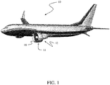
- FIG. 1 depicts a large commercial aircraft 10 employing high bypass ratio turbofan engines 12 having ultra-short nacelles 14.
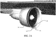
- a radial array 15 of individual flow control devices 16 providing a flow control system are deployed at the leading edge 18 of the nacelle 14 as seen in FIG. 2A (only the flow control device 16 in perpendicular section is shown deployed for clarity).
- Each flow control device 16 has a cambered body 17 rotatable from a stowed position as seen in FIGs. 3A-3D (described in greater detail subsequently) to the fully deployed position seen in FIG. 2A and in detail in FIG. 2B .
- Each flow control device 16 has a chord length 20 which is nominally 2.5 to 25% of the nacelle length 22.
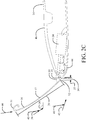
- FIGs. 2C-2E show the flow control device 16 in greater detail.
- Each flow control device 16 is rotated from the stowed to deployed position by an actuator 24 having an actuating rod 26 connected to the body of the flow control device 16, The flow control device 16 is then rotated about an axle 28 which supports the flow control device with lever arms 30 attached to the body 17 proximate a trailing edge 32 (in the deployed position).
- the axle 28 may incorporate one or more rotating shape memory alloy (SMA) tubes or similar devices for actuation.
- SMA rotating shape memory alloy
- the actuator 24 and associated actuating rod 26 are shown as attached to one of two lever arms 30, in alternative embodiments, a single lever arm 30 may be centrally connected to the body 17 of each flow control device 16.
- mechanical linkages may be employed to join adjacent flow control devices 16 and individual actuators 24 may rotate multiple flow control devices 16.
- the lever arms 30 are configured to maintain the nacelle leading edge 18 and flow control device trailing edge 32 in a spaced relationship providing a flow slot 34 with a width 35 of approximately 0.5 to 5% of the body chord length 20 ((best seen in FIG. 2D and exaggerated in the drawing for clarity).
- Deployment of the flow control devices 16 increases the effective camber of the leading edge of the nacelle.
- cambered shaping of the flow control device 16 from nose 31 to trailing edge 32 with angle of deployment 36 further enhances the significantly reduced initial turning angle 38 for an off-axis flow (such as a crosswind represented by arrows 40) with a smooth transition into the inlet as opposed to an initial turning angle 42 required by the aerodynamic internal contour 44 of the inlet without the deployed flow control device.
- camber in the flow control device 16 a flat contour maybe employed.
- the cambered contour provides additional benefit in aerodynamic smoothing of the flow control device 16 with the external contour 46 of the nacelle 14, as will be described in greater detail subsequently.
- a curved, blunt nose 31 aerodynamically assists air that is non-parallel to the flow control device turn onto the flow control device more easily.
- the lever arms 30 extend through slots 48 in the nacelle leading edge 18 (best seen in FIG. 2E ). As previously described a centrally located lever arm 30 may be attached to the flow control device 16 and extend through a single slot.
- a depressed pocket 50 in the external contour 46 seen in FIG. 2E , receives at least a portion of the flow control device 16 in the retracted position to provide a relatively flush transition between the nose 31 of the flow control device and the external contour 46 of the nacelle 14, as seen in FIGs. 3A-3D .
- Telescoping, jointed or pivoting mechanisms in the lever arms 30 may be employed to insert and engage the flow control device 16 within the pocket 50 during retraction to more closely meld with the external contour 46.
- FIGs. 3A-3E Closed or retracted
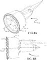
- FIGs. 4A-4C partially extended/rotated
- FIGs. 5A-5C fully rotated or extended.
- extension of the entire array of flow control devices 16 is symmetrical about a centerline axis 52 of the nacelle.
- selectable positioning of the flow control devices 16 at various points through the range of rotation may be desirable for varying angle of attack or other issues.
- FIG. 6 shows the symmetrical extended configuration of the radial array 15 of flow control devices 16.
- quadrants 54a-54c around the nacelle may have differing aerodynamic conditions or effects created by angle of attack of the aircraft as a whole, cross winds, which may be partially shielded or mitigated by the fuselage 56 of the aircraft, or other aerodynamic phenomenon induced during flight, takeoff or landing of the aircraft.
- Each of the flow control devices 16 may be separately operable for extension and retraction. For high angle of attack operation of the aircraft, deployment of selectable groups of the flow control devices 16 in at least lower outboard and lower inboard quadrants 54a and 54b would likely be desirable.
- the array of flow control devices may be altered to include only active devices in lower quadrants 54a and 54b, or those quadrants plus a lower portion of quadrants 54c and 54d which would be sufficient to accommodate all needed aerodynamic conditions.
- the embodiments disclosed herein provide a method for inlet flow control on an ultra-short turbofan engine nacelle as shown in FIG. 7 .
- a plurality of flow control devices 16 on each engine may be extended in at least lower quadrants 54a, 54b of the inlet circumference by rotating the body 17 of each flow control device about the leading edge 18 of the nacelle inlet, step 702.
- a predetermined outboard wind component i.e. blowing from the outboard side of the nacelle
- a plurality of flow control devices 16 may be extended in at least the outboard quadrants 54a, 54d of the inlet circumference, step 704.
- a plurality of flow control devices 16 may be extended in at least the inboard quadrants 54b, 54c of the inlet circumference, step 706, or where fuselage blocking or mitigation of the inboard cross wind is anticipated, flow control devices 16 in the upper inboard quadrant may remain retracted and only flow control devices 16 in the lower inboard quadrant are extended, step 708.
- all flow control devices 16 are retracted, step 710.
Landscapes
- Engineering & Computer Science (AREA)
- Chemical & Material Sciences (AREA)
- Combustion & Propulsion (AREA)
- Aviation & Aerospace Engineering (AREA)
- Mechanical Engineering (AREA)
- General Engineering & Computer Science (AREA)
- Physics & Mathematics (AREA)
- Geometry (AREA)
- Structures Of Non-Positive Displacement Pumps (AREA)
- Control Of Turbines (AREA)
Abstract
Description
- Exemplary embodiments of the disclosure relate generally to aerodynamic flow control for turbofan aircraft nacelles and more particularly to flow control devices on the leading lip of ultra-short nacelles.
- Turbofan engines are widely employed for large commercial aircraft. As engines become larger and fans become wider, nacelles housing the fans must become shorter to achieve lower fuel burns (lower drag and weight). However, shorter nacelles, especially the resulting shorter inlets means that at adverse conditions such as high angles of attack (takeoff and over-rotation) or crosswind conditions the flow is more likely to separate behind the leading edge of the short inlet. The short inlet's smaller leading edge radius, and other features, makes it more difficult for flow to stay attached when airflow entering the engine must turn before heading in a direction approximately normal to the fan-face. If the flow separates at the leading-edge of the nacelle, the resulting flow distortion (total pressure decrease) at the fan-face is undesirable. The separated flow may reduce performance, increase noise, and require heavier support structure to mitigate aerodynamically induced vibration. Existing solutions include simply making the inlet longer and adding a thicker lip. Alternatively blow-in doors used earlier nacelle designs may be employed. However, making the inlet longer is not an optimal solution with very large engine diameters as it reduces effectiveness of the larger engine by creating excess drag and weight. Blow-in doors increase emitted noise from aircraft operations and are structurally complex. It is therefore desirable to provide alternative solutions for inlet flow control which overcome the constraints of prior art solutions and provide improved performance.
- As disclosed herein a flow control system on an aircraft engine nacelle incorporates a plurality of flow control devices each having a body. An additional plurality of actuators is coupled to a trailing edge of the body of an associated one of the flow control devices. The actuator rotates the body about a leading edge of an inlet of a nacelle from a retracted position to an extended position.
- The embodiments disclosed provide a method for inlet flow control on an ultra-short turbofan engine nacelle by extending a plurality of flow control devices on each engine nacelle in at least lower quadrants of an inlet circumference accommodating a high angle of attack of the nacelle.
- The features, functions, and advantages desired can be achieved independently in various embodiments of the present disclosure or may be combined in yet other embodiments, further details of which can be seen with reference to the following description and drawings.
-
FIG. 1 is pictorial representation of a commercial aircraft with high bypass ratio turbofan engines; -
FIG. 2A is a pictorial detail of the turbofan engine nacelle as mounted on the aircraft wing; -
FIG. 2B is a partial section view of the inlet nacelle with an exemplary embodiment of the inlet flow control device as deployed demonstrating relative sizing of the flow control device and nacelle; -
FIG. 2C is a first detailed side view of the inlet flow control device in the deployed position; -
FIG. 2D is a second detailed lower angle pictorial view showing features of the inlet flow control device in the deployed position; -
FIG. 2E is a third detailed upper angle pictorial view showing features of the inlet flow control device in the deployed position; -
FIG. 3A is a front pictorial view of the inlet nacelle and engine with the flow control device in the stowed or retracted position; -
FIG. 3B is a side view of the inlet nacelle and engine with the flow control device in the stowed or retracted position; -
FIG. 3C is a rear pictorial view of the inlet nacelle and engine with the flow control device in the stowed or retracted position; -
FIG. 3D is a detailed upper angle pictorial view showing features of the inlet flow control device in the stowed position; -
FIG. 4A is a front pictorial view of the inlet nacelle and engine with the flow control device in a partially deployed position; -
FIG. 4B is a side view of the inlet nacelle and engine with the flow control device in a partially deployed position; -
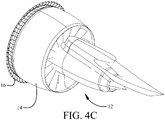
FIG. 4C is a rear pictorial view of the inlet nacelle and engine with the flow control device in a partially deployed position; -
FIG. 4D is a detailed side view showing features of the inlet flow control device in a partially deployed position; -
FIG. 5A is a front pictorial view of the inlet nacelle and engine with the flow control device in a fully deployed position; -
FIG. 5B is a side view of the inlet nacelle and engine with the flow control device in a fully deployed position; -
FIG. 5C is a rear pictorial view of the inlet nacelle and engine with the flow control device in a fully deployed position; -
FIG. 6 is a front view of the turbofan engine as mounted on the wing adjacent the fuselage with the flow control device in a fully deployed position; -
FIG. 7 is a flow chart depicting a method for flow control in a turbofan engine having a short inlet.. - The exemplary embodiments described herein provide flow control devices for adverse flow conditions in an ultra-short nacelle inlet to solve the problem of flow distortion on the fan for a larger turbofan engine. The flow control devices are a deployable aerodynamic structure, similar to a Krueger flap on an aircraft wing, that is deployed to extend from a leading edge of the nacelle to increase the effective leading edge radius of the nacelle and give incoming air flow a better turning angle to decrease or control flow separation in off- nominal conditions such as crosswind and high angles of attack. The resulting variable geometry inlet deals with low speed high angle-off-attack problems of separated flow, while still preserving the short nacelle in the retracted position to maintain cruise performance and the overall optimum performance of the larger engine.
- Referring to the drawings,
FIG. 1 depicts a largecommercial aircraft 10 employing high bypassratio turbofan engines 12 havingultra-short nacelles 14. Aradial array 15 of individualflow control devices 16 providing a flow control system are deployed at the leadingedge 18 of thenacelle 14 as seen inFIG. 2A (only theflow control device 16 in perpendicular section is shown deployed for clarity). Eachflow control device 16 has a camberedbody 17 rotatable from a stowed position as seen inFIGs. 3A-3D (described in greater detail subsequently) to the fully deployed position seen inFIG. 2A and in detail inFIG. 2B . Eachflow control device 16 has achord length 20 which is nominally 2.5 to 25% of thenacelle length 22. -
FIGs. 2C-2E show theflow control device 16 in greater detail. Eachflow control device 16 is rotated from the stowed to deployed position by anactuator 24 having an actuatingrod 26 connected to the body of theflow control device 16, Theflow control device 16 is then rotated about anaxle 28 which supports the flow control device withlever arms 30 attached to thebody 17 proximate a trailing edge 32 (in the deployed position). In alternative embodiments theaxle 28 may incorporate one or more rotating shape memory alloy (SMA) tubes or similar devices for actuation. While theactuator 24 and associated actuatingrod 26 are shown as attached to one of twolever arms 30, in alternative embodiments, asingle lever arm 30 may be centrally connected to thebody 17 of eachflow control device 16. Similarly, mechanical linkages may be employed to join adjacentflow control devices 16 andindividual actuators 24 may rotate multipleflow control devices 16. - The
lever arms 30 are configured to maintain thenacelle leading edge 18 and flow controldevice trailing edge 32 in a spaced relationship providing aflow slot 34 with awidth 35 of approximately 0.5 to 5% of the body chord length 20 ((best seen inFIG. 2D and exaggerated in the drawing for clarity). Deployment of theflow control devices 16 increases the effective camber of the leading edge of the nacelle. Additionally, cambered shaping of theflow control device 16 fromnose 31 to trailingedge 32 with angle ofdeployment 36 further enhances the significantly reducedinitial turning angle 38 for an off-axis flow (such as a crosswind represented by arrows 40) with a smooth transition into the inlet as opposed to aninitial turning angle 42 required by the aerodynamicinternal contour 44 of the inlet without the deployed flow control device. While the embodiment shown provides camber in theflow control device 16, a flat contour maybe employed. The cambered contour provides additional benefit in aerodynamic smoothing of theflow control device 16 with theexternal contour 46 of thenacelle 14, as will be described in greater detail subsequently. A curved,blunt nose 31 aerodynamically assists air that is non-parallel to the flow control device turn onto the flow control device more easily. - For the embodiment shown, the
lever arms 30 extend throughslots 48 in the nacelle leading edge 18 (best seen inFIG. 2E ). As previously described a centrally locatedlever arm 30 may be attached to theflow control device 16 and extend through a single slot. Adepressed pocket 50 in theexternal contour 46, seen inFIG. 2E , receives at least a portion of theflow control device 16 in the retracted position to provide a relatively flush transition between thenose 31 of the flow control device and theexternal contour 46 of thenacelle 14, as seen inFIGs. 3A-3D . Telescoping, jointed or pivoting mechanisms in thelever arms 30 may be employed to insert and engage theflow control device 16 within thepocket 50 during retraction to more closely meld with theexternal contour 46. - Deployment of the
flow control devices 16 is demonstrated in the sequence of drawings inFIGs. 3A-3E (closed or retracted),FIGs. 4A-4C (partially extended/rotated) andFIGs. 5A-5C (fully rotated or extended). As displayed in this sequence, extension of the entire array offlow control devices 16 is symmetrical about acenterline axis 52 of the nacelle. However, in certain embodiments selectable positioning of theflow control devices 16 at various points through the range of rotation may be desirable for varying angle of attack or other issues. -
FIG. 6 shows the symmetrical extended configuration of theradial array 15 offlow control devices 16. As annotated inFIG. 6 ,quadrants 54a-54c around the nacelle may have differing aerodynamic conditions or effects created by angle of attack of the aircraft as a whole, cross winds, which may be partially shielded or mitigated by thefuselage 56 of the aircraft, or other aerodynamic phenomenon induced during flight, takeoff or landing of the aircraft. Each of theflow control devices 16 may be separately operable for extension and retraction. For high angle of attack operation of the aircraft, deployment of selectable groups of theflow control devices 16 in at least lower outboard and lowerinboard quadrants outboard quadrants inboard quadrants fuselage 56 may block left cross wind flow and deployment of the flow control devices in upperinboard quadrant 54c may not be required. The descriptions herein are reversed for left and right designations for an engine mounted on the left side of the aircraft. Additionally, while shown in the drawings as equal quadrants, the "quadrants" may be interpreted as any selected arcuate segments of the circumference of the inlet. - For aircraft with certain operating conditions or engine mounting configurations, the array of flow control devices may be altered to include only active devices in
lower quadrants quadrants - The embodiments disclosed herein provide a method for inlet flow control on an ultra-short turbofan engine nacelle as shown in
FIG. 7 . For an expected predetermined high angle of attack condition a plurality offlow control devices 16 on each engine may be extended in at leastlower quadrants body 17 of each flow control device about the leadingedge 18 of the nacelle inlet, step 702. With a predetermined outboard wind component (i.e. blowing from the outboard side of the nacelle) a plurality offlow control devices 16 may be extended in at least theoutboard quadrants step 704. For a predetermined inboard cross wind component a plurality offlow control devices 16 may be extended in at least theinboard quadrants step 706, or where fuselage blocking or mitigation of the inboard cross wind is anticipated,flow control devices 16 in the upper inboard quadrant may remain retracted and only flowcontrol devices 16 in the lower inboard quadrant are extended,step 708. Upon exceeding a predetermined flight speed and/or reducing operation to a lower angle of attack, all flowcontrol devices 16 are retracted,step 710. - Further, the disclosure comprises embodiments according to the following clauses:
- 1. A flow control system on an engine nacelle, the system comprising:
- a plurality of flow control devices (16) each having a body (17); and
- a plurality of actuators (24), each actuator coupled to the body of at least one associated flow control device and configured to rotate the body about a leading edge (18) of an inlet of a nacelle (14) from a retracted position to an extended position and from the extended position to the retracted position.
- 2. The flow control system as defined in clause 1 wherein the body of each flow control device in the plurality of flow control devices has a nose (31) and a chord length (20) from the nose to a trailing edge (32) of about 2.5% to 20% of a length of the nacelle.
- 3. The flow control system as defined in clause 1 further comprising an axle (28) for each flow control device, said axle connected to each body with at least one lever arm (30), said axle configured for rotation by at least one of the plurality of actuators.
- 4. The flow control system as defined in clause 3 wherein said at least one lever arm is configured to maintain a spaced relationship between a trailing edge of the body and the leading edge of the inlet of the nacelle such that a flow slot (34) is formed therebetween.
- 5. The flow control system as defined in clause 4 wherein the flow slot has a slot width (35) of about 0.5% to 5% of a body chord length.
- 6. The flow control system as defined in clause 1 wherein the body is cambered.
- 7. The flow control system as defined in clause 6 further comprising a pocket (50) in an external contour (46) of the nacelle shaped to receive at least a portion of the body with a nose (31) of the body being substantially flush with the external contour of the nacelle.
- 8. The flow control system as defined in clause 1 wherein a number of actuators of the plurality of actuators is equal to a number of flow control devices of the plurality of flow control devices.
- 9. The flow control system as defined in clause 8 wherein each flow control device of the plurality of flow control devices is separately extendible.
- 10. The flow control system as defined in clause 1 wherein selectable groups of the plurality of flow control devices are simultaneously extendible.
- 11. The flow control system as defined in
clause 10 wherein at least two of the selectable groups are located in lower quadrants (54a, 54b) of a circumference of the inlet, wherein the at least two of the selectable groups are adapted to accommodate a high angle of attack of the inlet of the nacelle. - 12. The flow control system as defined in
clause 10 wherein at least two of the selectable groups are located in outboard quadrants (54a, 54d) of a circumference of the inlet, wherein the at least two of the selectable groups are adapted to accommodate outboard crosswind at the inlet of the nacelle. - 13. The flow control system as defined in
clause 10 wherein at least one of the selectable groups is located in an inboard quadrant (54b, 54c) of a circumference of the inlet, wherein the at least one of the selectable groups is adapted to accommodate inboard crosswind at the inlet of the nacelle. - 14. The flow control system as defined in clause 1 wherein each actuator is configured to rotate the body to a partially extended position between the retracted position and the extended position.
- 15. A method for inlet flow control on an engine nacelle comprising:
extending a plurality of flow control devices on a nacelle by rotating a body of each flow control device about a leading edge of an inlet of the nacelle. - 16. The method of
clause 15 wherein the plurality of flow control devices is extended in at least one lower quadrant of an inlet circumference to accommodate a high angle of attack of the inlet of the nacelle. - 17. The method of
clause 16 further comprising extending a plurality of flow control devices in at least one outboard quadrants of the inlet circumference accommodating a predetermined outboard wind component. - 18. The method of
clause 16 further comprising extending a plurality of flow control devices in at least one inboard quadrant of the inlet circumference accommodating a predetermined inboard wind component. - 19. The method of
clause 16 further comprising extending a plurality of flow control devices in a lower inboard quadrant of the inlet circumference accommodating a predetermined inboard wind component with a plurality of flow control devices in an upper inboard quadrant remaining retracted. - 20. The method of
clause 16 further comprising retracting all flow control devices upon exceeding a predetermined flight speed or operation at a lower angle of attack. - 21. An aircraft engine nacelle comprising:
- a leading edge (18) defining an inlet opening for air flow into a nacelle (14) ; and
- a plurality of flow control devices (16), each flow control device being rotatable about the leading edge between a retracted position and an extended position.
- 22. The aircraft engine nacelle as defined in clause 21 wherein selectable groups of the plurality of flow control devices are simultaneously extendible.
- Having now described various embodiments of the disclosure in detail as required by the patent statutes, those skilled in the art will recognize modifications and substitutions to the specific embodiments disclosed herein. Such modifications are within the scope and intent of the present disclosure as defined in the following claims.
Claims (15)
- A flow control system on an engine nacelle, the system comprising:a plurality of flow control devices (16) each having a body (17); anda second plurality of actuators (24), each actuator coupled to the body of at least one associated flow control device and configured to rotate the body about a leading edge (18) of an inlet of a nacelle (14) from a retracted position to an extended position.
- The flow control system as defined in claim 1 wherein the body of each flow control device in the plurality of flow control devices has a nose (31) and a chord length (20) from the nose to a trailing edge (32) of about 2.5% to 20% of a length of the nacelle.
- The flow control system as defined in claim 1 or 2 further comprising an axle (28) for each flow control device, said axle connected to each body with at least one lever arm (30), said axle configured for rotation by at least one of the second plurality of actuators.
- The flow control system as defined in claim 3 wherein said at least one lever arm is configured to maintain a spaced relationship between a trailing edge of the body and the leading edge of the inlet of the nacelle such that a flow slot (34) is formed therebetween, and optionally wherein the flow slot has a slot width (35) of about 0.5% to 5% of a body chord length.
- The flow control system as defined in any preceding claim wherein the body is cambered and optionally further comprising a pocket (50) in an external contour (46) of the nacelle shaped to receive at least a portion of the body with a nose (31) of the body being substantially flush with the external contour of the nacelle.
- The flow control system as defined in any preceding claim wherein a number of actuators of the second plurality of actuators is equal to a number of flow control devices of the plurality of flow control devices, and optionally wherein each flow control device of the plurality of flow control devices is separately extendible.
- The flow control system as defined in any preceding claim wherein selectable groups of the plurality of flow control devices are simultaneously extendible.
- The flow control system as defined in claim 7 wherein at least two of the selectable groups are located in lower quadrants (54a, 54b) of a circumference of the inlet, wherein the at least two of the selectable groups in the lower quadrants are adapted to accommodate a high angle of attack of the inlet of the nacelle.
- The flow control system as defined in claim 7 or 8 wherein at least two of the selectable groups are located in outboard quadrants (54a, 54d) of a circumference of the inlet, wherein the at least two of the selectable groups in the outboard quadrants are adapted to accommodate outboard crosswind at the inlet of the nacelle.
- The flow control system as defined in any one of claims 7-9 wherein at least one of the selectable groups is located in an inboard quadrant (54b, 54c) of a circumference of the inlet, wherein the at least one of the selectable groups in the inboard quadrant is adapted to accommodate inboard crosswind at the inlet of the nacelle.
- A method for inlet flow control on an engine nacelle comprising:
extending a plurality of flow control devices on a nacelle by rotating a body of each flow control device about a leading edge of an inlet of the nacelle in at least one lower quadrant of an inlet circumference accommodating a high angle of attack of the inlet of the nacelle. - The method of claim 11 further comprising extending a plurality of flow control devices in at least one outboard quadrant of the inlet circumference accommodating a predetermined outboard wind component.
- The method of claim 11 or 12 further comprising extending a plurality of flow control devices in at least one inboard quadrant of the inlet circumference accommodating a predetermined inboard wind component.
- The method of claim 11 or 12 further comprising extending a plurality of flow control devices in a lower inboard quadrant of the inlet circumference accommodating a predetermined inboard wind component with a plurality of flow control devices in an upper inboard quadrant remaining retracted.
- The method of any of claims 11 to 14 further comprising retracting all flow control devices upon exceeding a predetermined flight speed or operation at a lower angle of attack.
Applications Claiming Priority (1)
| Application Number | Priority Date | Filing Date | Title |
|---|---|---|---|
| US15/633,523 US20180371995A1 (en) | 2017-06-26 | 2017-06-26 | Rotating devices for mitigation of adverse flow conditions in an ultra-short nacelle inlet |
Publications (2)
| Publication Number | Publication Date |
|---|---|
| EP3421373A1 true EP3421373A1 (en) | 2019-01-02 |
| EP3421373B1 EP3421373B1 (en) | 2021-03-24 |
Family
ID=62791607
Family Applications (1)
| Application Number | Title | Priority Date | Filing Date |
|---|---|---|---|
| EP18179862.0A Active EP3421373B1 (en) | 2017-06-26 | 2018-06-26 | Rotating devices for mitigation of adverse flow conditions in an ultra-short nacelle inlet |
Country Status (5)
| Country | Link |
|---|---|
| US (1) | US20180371995A1 (en) |
| EP (1) | EP3421373B1 (en) |
| JP (1) | JP7074551B2 (en) |
| CN (1) | CN109110142B (en) |
| CA (1) | CA3003031C (en) |
Cited By (2)
| Publication number | Priority date | Publication date | Assignee | Title |
|---|---|---|---|---|
| WO2020212225A1 (en) | 2019-04-17 | 2020-10-22 | Safran Aircraft Engines | Process for using an air input of a turboreactor nacelle comprising an air input lip which comprises a portion which can be moved to promote a thrust inversion phase |
| WO2020212224A1 (en) | 2019-04-17 | 2020-10-22 | Safran Aircraft Engines | Turbojet engine comprising a nacelle with an air intake to support a reverse thrust phase |
Families Citing this family (7)
| Publication number | Priority date | Publication date | Assignee | Title |
|---|---|---|---|---|
| US11125157B2 (en) | 2017-09-22 | 2021-09-21 | The Boeing Company | Advanced inlet design |
| US10507548B2 (en) | 2017-09-29 | 2019-12-17 | The Boeing Company | Method for additive manufacturing nacelle inlet lipskins |
| US11420755B2 (en) * | 2019-08-08 | 2022-08-23 | General Electric Company | Shape memory alloy isolator for a gas turbine engine |
| FR3114615B1 (en) * | 2020-09-30 | 2024-01-12 | Safran Aircraft Engines | AIR INLET HANDLE FILTERING DISTORTION FOR A NACELLE OF AN AIRCRAFT PROPULSION ASSEMBLY |
| CN113252280B (en) * | 2021-04-20 | 2021-09-21 | 中国空气动力研究与发展中心高速空气动力研究所 | Nacelle test device capable of simulating air intake and exhaust simultaneously |
| BR102022003769A2 (en) | 2021-05-04 | 2022-11-16 | The Boeing Company | NACELE ENTRY STRUCTURE OF AN ENGINE ASSEMBLY |
| CN119124555B (en) * | 2024-11-13 | 2025-03-18 | 中国空气动力研究与发展中心超高速空气动力研究所 | Seesaw control method for air intake flow regulation of aircraft |
Citations (5)
| Publication number | Priority date | Publication date | Assignee | Title |
|---|---|---|---|---|
| US3652036A (en) * | 1968-10-24 | 1972-03-28 | Onera (Off Nat Aerospatiale) | Dynamic forced air intakes for vehicles |
| US3770228A (en) * | 1971-12-08 | 1973-11-06 | Lockheed Aircraft Corp | Air inlet flap |
| US6260567B1 (en) * | 1997-07-22 | 2001-07-17 | The Boeing Company | Mission adaptive inlet |
| EP1988266A2 (en) * | 2007-04-24 | 2008-11-05 | United Technologies Corporation | Nacelle assembly having inlet airfoil for a gas turbine engine |
| EP2003310A2 (en) * | 2007-06-15 | 2008-12-17 | United Technologies Corporation | Variable geometry nacelle for an aircraft engine |
Family Cites Families (12)
| Publication number | Priority date | Publication date | Assignee | Title |
|---|---|---|---|---|
| US3222863A (en) * | 1963-10-07 | 1965-12-14 | Boeing Co | Aerodynamic inlet |
| US3883095A (en) * | 1973-09-19 | 1975-05-13 | Nasa | Reversed cowl flap inlet thrust augmentor |
| JPS57151024A (en) * | 1981-03-16 | 1982-09-18 | Mitsubishi Heavy Ind Ltd | Construction of air intake port in aircraft |
| US4804155A (en) * | 1987-03-02 | 1989-02-14 | Strumbos William P | VTOL aircraft |
| DE3720318A1 (en) * | 1987-06-19 | 1989-01-05 | Mtu Muenchen Gmbh | GONDOLA FOR JET ENGINES |
| DE4009223A1 (en) * | 1990-03-22 | 1991-09-26 | Mtu Muenchen Gmbh | PROPFAN TURBO ENGINE |
| US6910327B2 (en) * | 2003-07-28 | 2005-06-28 | The Boeing Company | Apparatus and methods for varying inlet lip geometry of a jet engine inlet |
| US7386229B2 (en) * | 2006-08-04 | 2008-06-10 | Hoodman Corporation | Camera LCD screen hood and viewing device |
| US8402739B2 (en) * | 2007-06-28 | 2013-03-26 | United Technologies Corporation | Variable shape inlet section for a nacelle assembly of a gas turbine engine |
| US9169779B2 (en) * | 2007-10-09 | 2015-10-27 | United Technologies Corp. | Systems and methods for altering inlet airflow of gas turbine engines |
| US10107196B2 (en) * | 2014-08-08 | 2018-10-23 | Thomas International, Inc. | Adjustable size inlet system |
| US9964038B2 (en) * | 2015-03-16 | 2018-05-08 | The Boeing Company | Supersonic caret inlet system leading edge slat for improved inlet performance at off-design flight conditions |
-
2017
- 2017-06-26 US US15/633,523 patent/US20180371995A1/en not_active Abandoned
-
2018
- 2018-04-27 CA CA3003031A patent/CA3003031C/en active Active
- 2018-04-27 JP JP2018086735A patent/JP7074551B2/en active Active
- 2018-05-18 CN CN201810477885.2A patent/CN109110142B/en active Active
- 2018-06-26 EP EP18179862.0A patent/EP3421373B1/en active Active
Patent Citations (5)
| Publication number | Priority date | Publication date | Assignee | Title |
|---|---|---|---|---|
| US3652036A (en) * | 1968-10-24 | 1972-03-28 | Onera (Off Nat Aerospatiale) | Dynamic forced air intakes for vehicles |
| US3770228A (en) * | 1971-12-08 | 1973-11-06 | Lockheed Aircraft Corp | Air inlet flap |
| US6260567B1 (en) * | 1997-07-22 | 2001-07-17 | The Boeing Company | Mission adaptive inlet |
| EP1988266A2 (en) * | 2007-04-24 | 2008-11-05 | United Technologies Corporation | Nacelle assembly having inlet airfoil for a gas turbine engine |
| EP2003310A2 (en) * | 2007-06-15 | 2008-12-17 | United Technologies Corporation | Variable geometry nacelle for an aircraft engine |
Cited By (5)
| Publication number | Priority date | Publication date | Assignee | Title |
|---|---|---|---|---|
| WO2020212225A1 (en) | 2019-04-17 | 2020-10-22 | Safran Aircraft Engines | Process for using an air input of a turboreactor nacelle comprising an air input lip which comprises a portion which can be moved to promote a thrust inversion phase |
| WO2020212224A1 (en) | 2019-04-17 | 2020-10-22 | Safran Aircraft Engines | Turbojet engine comprising a nacelle with an air intake to support a reverse thrust phase |
| FR3095194A1 (en) | 2019-04-17 | 2020-10-23 | Safran Aircraft Engines | Turbojet nacelle air inlet comprising a deflection device to promote a thrust reversal phase |
| FR3095193A1 (en) * | 2019-04-17 | 2020-10-23 | Safran Aircraft Engines | Method of using a turbojet engine nacelle air inlet comprising an air inlet lip comprising a movable portion to promote a thrust reversal phase |
| US12134983B2 (en) | 2019-04-17 | 2024-11-05 | Safran Aircraft Engines | Process for using an air input of a turboreactor nacelle comprising an air input lip which comprises a portion which can be moved to promote a thrust inversion phase |
Also Published As
| Publication number | Publication date |
|---|---|
| CA3003031C (en) | 2022-06-28 |
| JP2019006374A (en) | 2019-01-17 |
| US20180371995A1 (en) | 2018-12-27 |
| EP3421373B1 (en) | 2021-03-24 |
| CA3003031A1 (en) | 2018-12-26 |
| CN109110142A (en) | 2019-01-01 |
| CN109110142B (en) | 2023-06-20 |
| JP7074551B2 (en) | 2022-05-24 |
Similar Documents
| Publication | Publication Date | Title |
|---|---|---|
| CA3003031C (en) | Rotating devices for mitigation of adverse flow conditions in an ultra-short nacelle inlet | |
| EP3421370B1 (en) | Translating turning vanes for a nacelle inlet | |
| CN103608260B (en) | Blade, particularly variable-pitch blade, comprise the screw propeller of this blade and corresponding turbo-machine | |
| CN101466597B (en) | Link mechanisms for gapped rigid krueger flaps, and associated systems and methods | |
| JP6214851B2 (en) | Method and apparatus for aircraft noise reduction | |
| EP2662282B1 (en) | Vortex generation | |
| EP2562082A2 (en) | An aircraft propulsion system and a method of controlling the same | |
| US20090230240A1 (en) | Aerodynamic fan control effector | |
| US20180093754A1 (en) | Translating fan blades for an aircraft tail mounted fan assembly | |
| JPH10176604A (en) | Variable exhaust nozzle for turbine engine | |
| EP3069999B1 (en) | Supersonic caret inlet system leading edge slat for improved inlet performance at off-design flight conditions | |
| US6910327B2 (en) | Apparatus and methods for varying inlet lip geometry of a jet engine inlet | |
| CA2719163C (en) | Improved slat configuration for fixed-wing aircraft | |
| US20250115349A1 (en) | Aircraft wing with leading edge spoiler | |
| US7278609B2 (en) | Movable nose cap and control strut assembly for supersonic aircraft | |
| CN214241213U (en) | an aircraft | |
| CN118391139A (en) | Variable geometry inlet for turboprop inlet pressure recovery optimization | |
| CN121916737A (en) | Sub-span super-span speed domain pneumatic layout of patrol projectile | |
| CN112407245A (en) | Aircraft |
Legal Events
| Date | Code | Title | Description |
|---|---|---|---|
| PUAI | Public reference made under article 153(3) epc to a published international application that has entered the european phase |
Free format text: ORIGINAL CODE: 0009012 |
|
| STAA | Information on the status of an ep patent application or granted ep patent |
Free format text: STATUS: REQUEST FOR EXAMINATION WAS MADE |
|
| 17P | Request for examination filed |
Effective date: 20180626 |
|
| AK | Designated contracting states |
Kind code of ref document: A1 Designated state(s): AL AT BE BG CH CY CZ DE DK EE ES FI FR GB GR HR HU IE IS IT LI LT LU LV MC MK MT NL NO PL PT RO RS SE SI SK SM TR |
|
| AX | Request for extension of the european patent |
Extension state: BA ME |
|
| STAA | Information on the status of an ep patent application or granted ep patent |
Free format text: STATUS: EXAMINATION IS IN PROGRESS |
|
| 17Q | First examination report despatched |
Effective date: 20191119 |
|
| GRAP | Despatch of communication of intention to grant a patent |
Free format text: ORIGINAL CODE: EPIDOSNIGR1 |
|
| STAA | Information on the status of an ep patent application or granted ep patent |
Free format text: STATUS: GRANT OF PATENT IS INTENDED |
|
| INTG | Intention to grant announced |
Effective date: 20201012 |
|
| GRAS | Grant fee paid |
Free format text: ORIGINAL CODE: EPIDOSNIGR3 |
|
| GRAA | (expected) grant |
Free format text: ORIGINAL CODE: 0009210 |
|
| STAA | Information on the status of an ep patent application or granted ep patent |
Free format text: STATUS: THE PATENT HAS BEEN GRANTED |
|
| AK | Designated contracting states |
Kind code of ref document: B1 Designated state(s): AL AT BE BG CH CY CZ DE DK EE ES FI FR GB GR HR HU IE IS IT LI LT LU LV MC MK MT NL NO PL PT RO RS SE SI SK SM TR |
|
| REG | Reference to a national code |
Ref country code: GB Ref legal event code: FG4D |
|
| REG | Reference to a national code |
Ref country code: CH Ref legal event code: EP |
|
| REG | Reference to a national code |
Ref country code: IE Ref legal event code: FG4D |
|
| REG | Reference to a national code |
Ref country code: AT Ref legal event code: REF Ref document number: 1374255 Country of ref document: AT Kind code of ref document: T Effective date: 20210415 Ref country code: DE Ref legal event code: R096 Ref document number: 602018014258 Country of ref document: DE |
|
| REG | Reference to a national code |
Ref country code: LT Ref legal event code: MG9D |
|
| PG25 | Lapsed in a contracting state [announced via postgrant information from national office to epo] |
Ref country code: NO Free format text: LAPSE BECAUSE OF FAILURE TO SUBMIT A TRANSLATION OF THE DESCRIPTION OR TO PAY THE FEE WITHIN THE PRESCRIBED TIME-LIMIT Effective date: 20210624 Ref country code: BG Free format text: LAPSE BECAUSE OF FAILURE TO SUBMIT A TRANSLATION OF THE DESCRIPTION OR TO PAY THE FEE WITHIN THE PRESCRIBED TIME-LIMIT Effective date: 20210624 Ref country code: GR Free format text: LAPSE BECAUSE OF FAILURE TO SUBMIT A TRANSLATION OF THE DESCRIPTION OR TO PAY THE FEE WITHIN THE PRESCRIBED TIME-LIMIT Effective date: 20210625 Ref country code: HR Free format text: LAPSE BECAUSE OF FAILURE TO SUBMIT A TRANSLATION OF THE DESCRIPTION OR TO PAY THE FEE WITHIN THE PRESCRIBED TIME-LIMIT Effective date: 20210324 Ref country code: FI Free format text: LAPSE BECAUSE OF FAILURE TO SUBMIT A TRANSLATION OF THE DESCRIPTION OR TO PAY THE FEE WITHIN THE PRESCRIBED TIME-LIMIT Effective date: 20210324 |
|
| PG25 | Lapsed in a contracting state [announced via postgrant information from national office to epo] |
Ref country code: SE Free format text: LAPSE BECAUSE OF FAILURE TO SUBMIT A TRANSLATION OF THE DESCRIPTION OR TO PAY THE FEE WITHIN THE PRESCRIBED TIME-LIMIT Effective date: 20210324 Ref country code: LV Free format text: LAPSE BECAUSE OF FAILURE TO SUBMIT A TRANSLATION OF THE DESCRIPTION OR TO PAY THE FEE WITHIN THE PRESCRIBED TIME-LIMIT Effective date: 20210324 Ref country code: RS Free format text: LAPSE BECAUSE OF FAILURE TO SUBMIT A TRANSLATION OF THE DESCRIPTION OR TO PAY THE FEE WITHIN THE PRESCRIBED TIME-LIMIT Effective date: 20210324 |
|
| REG | Reference to a national code |
Ref country code: NL Ref legal event code: MP Effective date: 20210324 |
|
| REG | Reference to a national code |
Ref country code: AT Ref legal event code: MK05 Ref document number: 1374255 Country of ref document: AT Kind code of ref document: T Effective date: 20210324 |
|
| PG25 | Lapsed in a contracting state [announced via postgrant information from national office to epo] |
Ref country code: NL Free format text: LAPSE BECAUSE OF FAILURE TO SUBMIT A TRANSLATION OF THE DESCRIPTION OR TO PAY THE FEE WITHIN THE PRESCRIBED TIME-LIMIT Effective date: 20210324 |
|
| PG25 | Lapsed in a contracting state [announced via postgrant information from national office to epo] |
Ref country code: CZ Free format text: LAPSE BECAUSE OF FAILURE TO SUBMIT A TRANSLATION OF THE DESCRIPTION OR TO PAY THE FEE WITHIN THE PRESCRIBED TIME-LIMIT Effective date: 20210324 Ref country code: EE Free format text: LAPSE BECAUSE OF FAILURE TO SUBMIT A TRANSLATION OF THE DESCRIPTION OR TO PAY THE FEE WITHIN THE PRESCRIBED TIME-LIMIT Effective date: 20210324 Ref country code: LT Free format text: LAPSE BECAUSE OF FAILURE TO SUBMIT A TRANSLATION OF THE DESCRIPTION OR TO PAY THE FEE WITHIN THE PRESCRIBED TIME-LIMIT Effective date: 20210324 Ref country code: SM Free format text: LAPSE BECAUSE OF FAILURE TO SUBMIT A TRANSLATION OF THE DESCRIPTION OR TO PAY THE FEE WITHIN THE PRESCRIBED TIME-LIMIT Effective date: 20210324 Ref country code: AT Free format text: LAPSE BECAUSE OF FAILURE TO SUBMIT A TRANSLATION OF THE DESCRIPTION OR TO PAY THE FEE WITHIN THE PRESCRIBED TIME-LIMIT Effective date: 20210324 |
|
| PG25 | Lapsed in a contracting state [announced via postgrant information from national office to epo] |
Ref country code: SK Free format text: LAPSE BECAUSE OF FAILURE TO SUBMIT A TRANSLATION OF THE DESCRIPTION OR TO PAY THE FEE WITHIN THE PRESCRIBED TIME-LIMIT Effective date: 20210324 Ref country code: RO Free format text: LAPSE BECAUSE OF FAILURE TO SUBMIT A TRANSLATION OF THE DESCRIPTION OR TO PAY THE FEE WITHIN THE PRESCRIBED TIME-LIMIT Effective date: 20210324 Ref country code: PL Free format text: LAPSE BECAUSE OF FAILURE TO SUBMIT A TRANSLATION OF THE DESCRIPTION OR TO PAY THE FEE WITHIN THE PRESCRIBED TIME-LIMIT Effective date: 20210324 Ref country code: PT Free format text: LAPSE BECAUSE OF FAILURE TO SUBMIT A TRANSLATION OF THE DESCRIPTION OR TO PAY THE FEE WITHIN THE PRESCRIBED TIME-LIMIT Effective date: 20210726 Ref country code: IS Free format text: LAPSE BECAUSE OF FAILURE TO SUBMIT A TRANSLATION OF THE DESCRIPTION OR TO PAY THE FEE WITHIN THE PRESCRIBED TIME-LIMIT Effective date: 20210724 |
|
| REG | Reference to a national code |
Ref country code: DE Ref legal event code: R097 Ref document number: 602018014258 Country of ref document: DE |
|
| PG25 | Lapsed in a contracting state [announced via postgrant information from national office to epo] |
Ref country code: ES Free format text: LAPSE BECAUSE OF FAILURE TO SUBMIT A TRANSLATION OF THE DESCRIPTION OR TO PAY THE FEE WITHIN THE PRESCRIBED TIME-LIMIT Effective date: 20210324 Ref country code: MC Free format text: LAPSE BECAUSE OF FAILURE TO SUBMIT A TRANSLATION OF THE DESCRIPTION OR TO PAY THE FEE WITHIN THE PRESCRIBED TIME-LIMIT Effective date: 20210324 Ref country code: AL Free format text: LAPSE BECAUSE OF FAILURE TO SUBMIT A TRANSLATION OF THE DESCRIPTION OR TO PAY THE FEE WITHIN THE PRESCRIBED TIME-LIMIT Effective date: 20210324 Ref country code: DK Free format text: LAPSE BECAUSE OF FAILURE TO SUBMIT A TRANSLATION OF THE DESCRIPTION OR TO PAY THE FEE WITHIN THE PRESCRIBED TIME-LIMIT Effective date: 20210324 |
|
| REG | Reference to a national code |
Ref country code: CH Ref legal event code: PL |
|
| PLBE | No opposition filed within time limit |
Free format text: ORIGINAL CODE: 0009261 |
|
| STAA | Information on the status of an ep patent application or granted ep patent |
Free format text: STATUS: NO OPPOSITION FILED WITHIN TIME LIMIT |
|
| PG25 | Lapsed in a contracting state [announced via postgrant information from national office to epo] |
Ref country code: SI Free format text: LAPSE BECAUSE OF FAILURE TO SUBMIT A TRANSLATION OF THE DESCRIPTION OR TO PAY THE FEE WITHIN THE PRESCRIBED TIME-LIMIT Effective date: 20210324 |
|
| 26N | No opposition filed |
Effective date: 20220104 |
|
| REG | Reference to a national code |
Ref country code: BE Ref legal event code: MM Effective date: 20210630 |
|
| PG25 | Lapsed in a contracting state [announced via postgrant information from national office to epo] |
Ref country code: LU Free format text: LAPSE BECAUSE OF NON-PAYMENT OF DUE FEES Effective date: 20210626 |
|
| PG25 | Lapsed in a contracting state [announced via postgrant information from national office to epo] |
Ref country code: LI Free format text: LAPSE BECAUSE OF NON-PAYMENT OF DUE FEES Effective date: 20210630 Ref country code: IE Free format text: LAPSE BECAUSE OF NON-PAYMENT OF DUE FEES Effective date: 20210626 Ref country code: CH Free format text: LAPSE BECAUSE OF NON-PAYMENT OF DUE FEES Effective date: 20210630 |
|
| PG25 | Lapsed in a contracting state [announced via postgrant information from national office to epo] |
Ref country code: IS Free format text: LAPSE BECAUSE OF FAILURE TO SUBMIT A TRANSLATION OF THE DESCRIPTION OR TO PAY THE FEE WITHIN THE PRESCRIBED TIME-LIMIT Effective date: 20210724 |
|
| PG25 | Lapsed in a contracting state [announced via postgrant information from national office to epo] |
Ref country code: BE Free format text: LAPSE BECAUSE OF NON-PAYMENT OF DUE FEES Effective date: 20210630 |
|
| PG25 | Lapsed in a contracting state [announced via postgrant information from national office to epo] |
Ref country code: IT Free format text: LAPSE BECAUSE OF FAILURE TO SUBMIT A TRANSLATION OF THE DESCRIPTION OR TO PAY THE FEE WITHIN THE PRESCRIBED TIME-LIMIT Effective date: 20210324 |
|
| P01 | Opt-out of the competence of the unified patent court (upc) registered |
Effective date: 20230516 |
|
| PG25 | Lapsed in a contracting state [announced via postgrant information from national office to epo] |
Ref country code: CY Free format text: LAPSE BECAUSE OF FAILURE TO SUBMIT A TRANSLATION OF THE DESCRIPTION OR TO PAY THE FEE WITHIN THE PRESCRIBED TIME-LIMIT Effective date: 20210324 |
|
| PG25 | Lapsed in a contracting state [announced via postgrant information from national office to epo] |
Ref country code: HU Free format text: LAPSE BECAUSE OF FAILURE TO SUBMIT A TRANSLATION OF THE DESCRIPTION OR TO PAY THE FEE WITHIN THE PRESCRIBED TIME-LIMIT; INVALID AB INITIO Effective date: 20180626 |
|
| PG25 | Lapsed in a contracting state [announced via postgrant information from national office to epo] |
Ref country code: MK Free format text: LAPSE BECAUSE OF FAILURE TO SUBMIT A TRANSLATION OF THE DESCRIPTION OR TO PAY THE FEE WITHIN THE PRESCRIBED TIME-LIMIT Effective date: 20210324 |
|
| PG25 | Lapsed in a contracting state [announced via postgrant information from national office to epo] |
Ref country code: TR Free format text: LAPSE BECAUSE OF FAILURE TO SUBMIT A TRANSLATION OF THE DESCRIPTION OR TO PAY THE FEE WITHIN THE PRESCRIBED TIME-LIMIT Effective date: 20210324 |
|
| PG25 | Lapsed in a contracting state [announced via postgrant information from national office to epo] |
Ref country code: MT Free format text: LAPSE BECAUSE OF FAILURE TO SUBMIT A TRANSLATION OF THE DESCRIPTION OR TO PAY THE FEE WITHIN THE PRESCRIBED TIME-LIMIT Effective date: 20210324 |
|
| PGFP | Annual fee paid to national office [announced via postgrant information from national office to epo] |
Ref country code: DE Payment date: 20250627 Year of fee payment: 8 |
|
| PGFP | Annual fee paid to national office [announced via postgrant information from national office to epo] |
Ref country code: GB Payment date: 20250627 Year of fee payment: 8 |
|
| PGFP | Annual fee paid to national office [announced via postgrant information from national office to epo] |
Ref country code: FR Payment date: 20250625 Year of fee payment: 8 |