EP3421370A1 - Translating turning vanes for a nacelle inlet - Google Patents
Translating turning vanes for a nacelle inlet Download PDFInfo
- Publication number
- EP3421370A1 EP3421370A1 EP18179867.9A EP18179867A EP3421370A1 EP 3421370 A1 EP3421370 A1 EP 3421370A1 EP 18179867 A EP18179867 A EP 18179867A EP 3421370 A1 EP3421370 A1 EP 3421370A1
- Authority
- EP
- European Patent Office
- Prior art keywords
- nacelle
- cascade
- translating
- translating turning
- flow control
- Prior art date
- Legal status (The legal status is an assumption and is not a legal conclusion. Google has not performed a legal analysis and makes no representation as to the accuracy of the status listed.)
- Granted
Links
Images








Classifications
-
- F—MECHANICAL ENGINEERING; LIGHTING; HEATING; WEAPONS; BLASTING
- F01—MACHINES OR ENGINES IN GENERAL; ENGINE PLANTS IN GENERAL; STEAM ENGINES
- F01D—NON-POSITIVE DISPLACEMENT MACHINES OR ENGINES, e.g. STEAM TURBINES
- F01D9/00—Stators
- F01D9/02—Nozzles; Nozzle boxes; Stator blades; Guide conduits, e.g. individual nozzles
- F01D9/04—Nozzles; Nozzle boxes; Stator blades; Guide conduits, e.g. individual nozzles forming ring or sector
- F01D9/041—Nozzles; Nozzle boxes; Stator blades; Guide conduits, e.g. individual nozzles forming ring or sector using blades
-
- F—MECHANICAL ENGINEERING; LIGHTING; HEATING; WEAPONS; BLASTING
- F02—COMBUSTION ENGINES; HOT-GAS OR COMBUSTION-PRODUCT ENGINE PLANTS
- F02C—GAS-TURBINE PLANTS; AIR INTAKES FOR JET-PROPULSION PLANTS; CONTROLLING FUEL SUPPLY IN AIR-BREATHING JET-PROPULSION PLANTS
- F02C7/00—Features, components parts, details or accessories, not provided for in, or of interest apart form groups F02C1/00 - F02C6/00; Air intakes for jet-propulsion plants
- F02C7/04—Air intakes for gas-turbine plants or jet-propulsion plants
- F02C7/042—Air intakes for gas-turbine plants or jet-propulsion plants having variable geometry
-
- B—PERFORMING OPERATIONS; TRANSPORTING
- B64—AIRCRAFT; AVIATION; COSMONAUTICS
- B64D—EQUIPMENT FOR FITTING IN OR TO AIRCRAFT; FLIGHT SUITS; PARACHUTES; ARRANGEMENT OR MOUNTING OF POWER PLANTS OR PROPULSION TRANSMISSIONS IN AIRCRAFT
- B64D27/00—Arrangement or mounting of power plants in aircraft; Aircraft characterised by the type or position of power plants
- B64D27/02—Aircraft characterised by the type or position of power plants
- B64D27/16—Aircraft characterised by the type or position of power plants of jet type
- B64D27/18—Aircraft characterised by the type or position of power plants of jet type within, or attached to, wings
-
- B—PERFORMING OPERATIONS; TRANSPORTING
- B64—AIRCRAFT; AVIATION; COSMONAUTICS
- B64D—EQUIPMENT FOR FITTING IN OR TO AIRCRAFT; FLIGHT SUITS; PARACHUTES; ARRANGEMENT OR MOUNTING OF POWER PLANTS OR PROPULSION TRANSMISSIONS IN AIRCRAFT
- B64D29/00—Power-plant nacelles, fairings or cowlings
- B64D29/06—Attaching of nacelles, fairings or cowlings
-
- B—PERFORMING OPERATIONS; TRANSPORTING
- B64—AIRCRAFT; AVIATION; COSMONAUTICS
- B64D—EQUIPMENT FOR FITTING IN OR TO AIRCRAFT; FLIGHT SUITS; PARACHUTES; ARRANGEMENT OR MOUNTING OF POWER PLANTS OR PROPULSION TRANSMISSIONS IN AIRCRAFT
- B64D33/00—Arrangement in aircraft of power plant parts or auxiliaries not otherwise provided for
- B64D33/02—Arrangement in aircraft of power plant parts or auxiliaries not otherwise provided for of combustion air intakes
-
- F—MECHANICAL ENGINEERING; LIGHTING; HEATING; WEAPONS; BLASTING
- F01—MACHINES OR ENGINES IN GENERAL; ENGINE PLANTS IN GENERAL; STEAM ENGINES
- F01D—NON-POSITIVE DISPLACEMENT MACHINES OR ENGINES, e.g. STEAM TURBINES
- F01D17/00—Regulating or controlling by varying flow
- F01D17/10—Final actuators
- F01D17/12—Final actuators arranged in stator parts
- F01D17/14—Final actuators arranged in stator parts varying effective cross-sectional area of nozzles or guide conduits
- F01D17/16—Final actuators arranged in stator parts varying effective cross-sectional area of nozzles or guide conduits by means of nozzle vanes
- F01D17/162—Final actuators arranged in stator parts varying effective cross-sectional area of nozzles or guide conduits by means of nozzle vanes for axial flow, i.e. the vanes turning around axes which are essentially perpendicular to the rotor centre line
-
- F—MECHANICAL ENGINEERING; LIGHTING; HEATING; WEAPONS; BLASTING
- F02—COMBUSTION ENGINES; HOT-GAS OR COMBUSTION-PRODUCT ENGINE PLANTS
- F02C—GAS-TURBINE PLANTS; AIR INTAKES FOR JET-PROPULSION PLANTS; CONTROLLING FUEL SUPPLY IN AIR-BREATHING JET-PROPULSION PLANTS
- F02C7/00—Features, components parts, details or accessories, not provided for in, or of interest apart form groups F02C1/00 - F02C6/00; Air intakes for jet-propulsion plants
- F02C7/04—Air intakes for gas-turbine plants or jet-propulsion plants
-
- F—MECHANICAL ENGINEERING; LIGHTING; HEATING; WEAPONS; BLASTING
- F02—COMBUSTION ENGINES; HOT-GAS OR COMBUSTION-PRODUCT ENGINE PLANTS
- F02C—GAS-TURBINE PLANTS; AIR INTAKES FOR JET-PROPULSION PLANTS; CONTROLLING FUEL SUPPLY IN AIR-BREATHING JET-PROPULSION PLANTS
- F02C7/00—Features, components parts, details or accessories, not provided for in, or of interest apart form groups F02C1/00 - F02C6/00; Air intakes for jet-propulsion plants
- F02C7/04—Air intakes for gas-turbine plants or jet-propulsion plants
- F02C7/057—Control or regulation
-
- F—MECHANICAL ENGINEERING; LIGHTING; HEATING; WEAPONS; BLASTING
- F02—COMBUSTION ENGINES; HOT-GAS OR COMBUSTION-PRODUCT ENGINE PLANTS
- F02K—JET-PROPULSION PLANTS
- F02K3/00—Plants including a gas turbine driving a compressor or a ducted fan
- F02K3/02—Plants including a gas turbine driving a compressor or a ducted fan in which part of the working fluid by-passes the turbine and combustion chamber
- F02K3/04—Plants including a gas turbine driving a compressor or a ducted fan in which part of the working fluid by-passes the turbine and combustion chamber the plant including ducted fans, i.e. fans with high volume, low pressure outputs, for augmenting the jet thrust, e.g. of double-flow type
- F02K3/06—Plants including a gas turbine driving a compressor or a ducted fan in which part of the working fluid by-passes the turbine and combustion chamber the plant including ducted fans, i.e. fans with high volume, low pressure outputs, for augmenting the jet thrust, e.g. of double-flow type with front fan
-
- F—MECHANICAL ENGINEERING; LIGHTING; HEATING; WEAPONS; BLASTING
- F02—COMBUSTION ENGINES; HOT-GAS OR COMBUSTION-PRODUCT ENGINE PLANTS
- F02K—JET-PROPULSION PLANTS
- F02K3/00—Plants including a gas turbine driving a compressor or a ducted fan
- F02K3/02—Plants including a gas turbine driving a compressor or a ducted fan in which part of the working fluid by-passes the turbine and combustion chamber
- F02K3/04—Plants including a gas turbine driving a compressor or a ducted fan in which part of the working fluid by-passes the turbine and combustion chamber the plant including ducted fans, i.e. fans with high volume, low pressure outputs, for augmenting the jet thrust, e.g. of double-flow type
- F02K3/068—Plants including a gas turbine driving a compressor or a ducted fan in which part of the working fluid by-passes the turbine and combustion chamber the plant including ducted fans, i.e. fans with high volume, low pressure outputs, for augmenting the jet thrust, e.g. of double-flow type being characterised by a short axial length relative to the diameter
-
- F—MECHANICAL ENGINEERING; LIGHTING; HEATING; WEAPONS; BLASTING
- F02—COMBUSTION ENGINES; HOT-GAS OR COMBUSTION-PRODUCT ENGINE PLANTS
- F02K—JET-PROPULSION PLANTS
- F02K1/00—Plants characterised by the form or arrangement of the jet pipe or nozzle; Jet pipes or nozzles peculiar thereto
- F02K1/002—Plants characterised by the form or arrangement of the jet pipe or nozzle; Jet pipes or nozzles peculiar thereto with means to modify the direction of thrust vector
- F02K1/006—Plants characterised by the form or arrangement of the jet pipe or nozzle; Jet pipes or nozzles peculiar thereto with means to modify the direction of thrust vector within one plane only
-
- F—MECHANICAL ENGINEERING; LIGHTING; HEATING; WEAPONS; BLASTING
- F05—INDEXING SCHEMES RELATING TO ENGINES OR PUMPS IN VARIOUS SUBCLASSES OF CLASSES F01-F04
- F05D—INDEXING SCHEME FOR ASPECTS RELATING TO NON-POSITIVE-DISPLACEMENT MACHINES OR ENGINES, GAS-TURBINES OR JET-PROPULSION PLANTS
- F05D2250/00—Geometry
- F05D2250/50—Inlet or outlet
- F05D2250/51—Inlet
- F05D2250/511—Inlet augmenting, i.e. with intercepting fluid flow cross sectional area greater than the rest of the machine behind the inlet
-
- F—MECHANICAL ENGINEERING; LIGHTING; HEATING; WEAPONS; BLASTING
- F05—INDEXING SCHEMES RELATING TO ENGINES OR PUMPS IN VARIOUS SUBCLASSES OF CLASSES F01-F04
- F05D—INDEXING SCHEME FOR ASPECTS RELATING TO NON-POSITIVE-DISPLACEMENT MACHINES OR ENGINES, GAS-TURBINES OR JET-PROPULSION PLANTS
- F05D2260/00—Function
- F05D2260/96—Preventing, counteracting or reducing vibration or noise
- F05D2260/961—Preventing, counteracting or reducing vibration or noise by mistuning rotor blades or stator vanes with irregular interblade spacing, airfoil shape
Definitions
- Exemplary embodiments of the disclosure relate generally to aerodynamic flow control for turbofan aircraft nacelles and more particularly to translating turning vanes on the leading lip of ultra-short nacelles.
- Turbofan engines are widely employed for large commercial aircraft. As engines become larger and fans become wider, nacelles housing the fans must become shorter to achieve lower fuel burns. However, shorter nacelles, especially the resulting shorter inlets means that at adverse conditions such as high angles of attack or crosswind conditions the flow is more likely to separate behind the leading edge of the short inlet.
- the short inlet's smaller leading edge radius, and other features, makes it more difficult for flow to stay attached when airflow entering the engine must turn before heading in a direction approximately normal to the fan-face. If the flow separates at the leading-edge of the nacelle, the resulting distortion at the fan-face is undesirable. The separated flow may reduce performance, increase noise, and require heavier support structure to mitigate aerodynamically induced vibration.
- Existing solutions include simply making the inlet longer.
- blow-in doors used in earlier nacelle designs may be employed.
- making the inlet longer is not viable option in many applications as it reduces effectiveness of the larger engine by creating excess drag and weight.
- Blow-in doors increase emitted noise from aircraft operations and are structurally complex. It is therefore desirable to provide alternative solutions for inlet flow control which overcome the constraints of prior art solutions and provide improved performance.
- a flow control system on an aircraft engine nacelle incorporates a cascade of translating turning vanes supported to extend from a leading edge of a nacelle. At least one actuator is coupled to the cascade of translating turning vanes to translate the cascade from a retracted position to an extended position.
- the exemplary embodiments disclosed provide a method for inlet flow control on an ultra-short turbofan engine nacelle by extending a plurality of translating turning vanes on each engine nacelle in at least lower quadrants of an inlet circumference accommodating a high angle of attack of the nacelle.
- the exemplary embodiments described herein provide translating multiple element turning vanes for adverse flow conditions in an ultra-short nacelle inlet to solve the problem of flow distortion on the fan face of the engine.
- the multiple element turning vanes are a deployable aerodynamic structure having a vane cascade with varying airfoil sections which are extended from the leading edge of the nacelle to decrease or eliminate flow separation from the inlet inner contour in off-nominal conditions such as crosswind and high angles of attack.
- the resulting variable geometry inlet deals with low speed and high angle of attack problems of separated flow, while still preserving the short nacelle by retracting into a recess in the nacelle leading edge to maintain cruise performance and the overall optimum performance of the larger engine.
- FIG. 1 depicts a large commercial aircraft 10 employing high bypass ratio turbofan engines 12 having ultra-short nacelles 14.
- a radial cascade 15 of translating turning vanes are configured to be deployed around a leading edge 18 of the nacelle 14 in translating turning vane segments 16 as seen in FIG. 2A .
- the leading edge 18 circumscribes an inlet 13 providing air flow into the nacelle 14 for the turbofan engine 12.
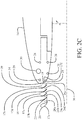
- the cascade 15 of extendible turning vanes translates to be positionable over a range from a stowed or retracted position as seen in FIGs. 3A-3D to the fully deployed or extended position seen in FIG. 2A and in detail in FIGs. 2B and 2C .
- the cascade 15 of extendible turning vanes provides a flow control system to reduce flow distortion in the inlet.
- Each translating turning vane segment 16 has a nose vane 17a, and multiple trailing vanes 17b, 17c, 17d and 17e supported by longitudinal ribs 19.
- the nose vane 17a has an outer contour 20 matching the nose contour of the leading edge 18, whereby in the retracted position, laminar flow of the inlet may be substantially maintained.
- a closing vane 17f again has an outer contour 21 matching the contour of the leading edge 18 to provide a smooth aerodynamic transition with the translating turning vane segment 16 in the fully extended position aligning the closing vane 17f with the leading edge 18.
- vanes 17b-17e may have differing airfoil shapes and chord for tailoring the aerodynamics of flow turning as required.
- the radial cascade 15 of extendable translating turning vane segments 16 has fully extended length 22 which is determined based on the number and spacing of vanes 17a-17e but is nominally 2.5-20% of the nacelle length 24.
- the nose vane 17a and four additional vanes 17b-17e are used. In alternative embodiments between 2 and 10 vanes may be employed.
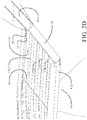
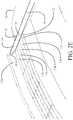
- FIGs. 2D-2E show the translating turning vane segment 16 in alternate views for clarity.
- the entire radial cascade 15 may be a single element which is extended from the leading edge 18 as a unit or cartridge with a continuous nose vane 17a.
- the radial cascade 15 may be split into quadrants, individually operable to extend translating turning vane segments 16 or other desired segments spanning a portion of the circumference of the leading edge 18 for operational sequencing as will be described in greater detail subsequently.
- the description is provided herein in terms of an individual translating turning vane segment 16.
- the ribs 19 support the vanes 17a - 17e to provide spacing of flow channels or slots 26a - 26e between the vanes. Deployment of the translating turning vane segments 16 increases the effective chord of the nacelle.
- the ribs 19 are supported by a plurality of bearings 28 for longitudinal extension from and retraction into the nacelle 14.
- a plurality of actuators such as rollers 30, which may be pinion gears engaging a gear rack in the ribs 19, are engaged to extend or retract the translating turning vane segments 16 in the cascade 15. Stepper motors or similar devices may be employed to drive the pinion gears for precise extension length for partial and full extension. In alternative embodiments, linear actuators may be employed to extend and retract the translating turning vane segments 16.
- multiple vane segments 16 may be interconnected by mechanical or hydraulic linkages and the number of individual ribs or segments driven by separate actuators may vary.
- a single actuator may be employed to extend the entire cascade 15.
- one or more of the vanes 17a-17e in the translating turning vane segments 16 may be rotatable about an axis 23 (represented in FIG. 2C ).
- the outer extent of a slotted opening 32 in the leading edge 18 (best seen in FIGs. 2D and 2E ), through which the cascade 15 is extended and retracted, has an outer edge 34 relative to a nacelle inlet centerline 36 (seen in FIG. 2C ) substantially aligned with a nominal cruise condition stagnation point 38 on the nacelle leading edge 18.
- the cascade 15 is thus positioned radially inward from the stagnation point 38 to avoid interrupting flow on the exterior contour of the nacelle 14 for reduced drag at cruise.
- Matching of the outer contour 20 of the nose vane 17a to the contour of the leading edge of the nacelle reduces flow disruption on the internal surface of the inlet with the cascade 15 retracted for cruise conditions to minimize aerodynamic drag at cruise.
- the slotted opening 32 opens into a recess 33 in the nacelle 14 to house the cascade 15.
- FIGs. 3A-3C Closed or retracted
- FIGs. 4A-4C partially extended
- FIGs. 5A-5C fully extended
- Exemplary embodiments will typically be operated at either the stowed/retracted or fully extended positions.
- multiple partially extended positions may be employed, exposing differing numbers of vanes and slots to match aerodynamic operating requirements.
- extension of the entire radial cascade 15 of translating turning vane segments 16 is symmetrical about the nacelle inlet centerline 36.
- the partially extended translating turning vane segment 16 provides an intermediate chord extension for the nacelle 14.
- Intermediate vane 17d has a contour comparable to the outer contour 21 of closing vane 17f to provide flow smoothing around and substantially close the slot 32 in the nacelle leading edge with the segment in the partially extended position.
- FIG. 6 shows the symmetrical extended configuration of the radial cascade 15 of translating turning vane segments 16.
- quadrants 40a-40d around the nacelle may have differing aerodynamic conditions or effects created by angle of attack of the aircraft as a whole, cross winds, which may be partially shielded or mitigated by the fuselage 42 of the aircraft, or other aerodynamic phenomenon induced during flight, takeoff or landing of the aircraft.
- Each of the translating turning vane segments 16 may be separately operable for extension and retraction. For high angle of attack operation of the aircraft, deployment of selectable groups of the translating turning vane segments 16 in at least lower outboard and lower inboard quadrants 40a and 40b would likely be desirable.
- the cascade of translating turning vane segments may be altered to include only active devices in lower quadrants 40a and 40b, or those quadrants plus a lower portion of quadrants 40c and 40d which would be sufficient to accommodate all needed aerodynamic conditions.
- the embodiments disclosed herein provide a method for inlet flow control on an ultra-short turbofan engine nacelle as shown in FIG. 7 .
- the cascade 15 of translating turning vane segments 16 may be extended to a partially extended position, step 702.
- the cascade 15 of translating turning vane segments 16 is fully extended, step 704.
- a plurality of translating turning vane segments 16 on each engine may be extended in at least lower quadrants 40a, 40b of the inlet circumference by extending the ribs of each translating turning vane segment through the leading edge 18 of the inlet, step 706.
- a plurality of translating turning vanes segments 16 may be extended in at least the outboard quadrants 40a, 40d of the inlet circumference, step 708.
- a predetermined inboard cross wind component a plurality of translating turning vane segments 16 may be extended in at least the inboard quadrants 40b, 40c of the inlet circumference, step 710, or where fuselage blocking or mitigation of the inboard cross wind is anticipated, translating turning vane segments 16 in the upper inboard quadrant may remain retracted and only translating turning vanes segments 16 in the lower inboard quadrant are extended, step 712.
- all translating turning vane segments 16 are retracted, step 714.
Landscapes
- Engineering & Computer Science (AREA)
- Chemical & Material Sciences (AREA)
- Combustion & Propulsion (AREA)
- Mechanical Engineering (AREA)
- General Engineering & Computer Science (AREA)
- Aviation & Aerospace Engineering (AREA)
- Physics & Mathematics (AREA)
- Geometry (AREA)
- Structures Of Non-Positive Displacement Pumps (AREA)
Abstract
Description
- Exemplary embodiments of the disclosure relate generally to aerodynamic flow control for turbofan aircraft nacelles and more particularly to translating turning vanes on the leading lip of ultra-short nacelles.
- Turbofan engines are widely employed for large commercial aircraft. As engines become larger and fans become wider, nacelles housing the fans must become shorter to achieve lower fuel burns. However, shorter nacelles, especially the resulting shorter inlets means that at adverse conditions such as high angles of attack or crosswind conditions the flow is more likely to separate behind the leading edge of the short inlet. The short inlet's smaller leading edge radius, and other features, makes it more difficult for flow to stay attached when airflow entering the engine must turn before heading in a direction approximately normal to the fan-face. If the flow separates at the leading-edge of the nacelle, the resulting distortion at the fan-face is undesirable. The separated flow may reduce performance, increase noise, and require heavier support structure to mitigate aerodynamically induced vibration. Existing solutions include simply making the inlet longer. Alternatively blow-in doors used in earlier nacelle designs may be employed. However, making the inlet longer is not viable option in many applications as it reduces effectiveness of the larger engine by creating excess drag and weight. Blow-in doors increase emitted noise from aircraft operations and are structurally complex. It is therefore desirable to provide alternative solutions for inlet flow control which overcome the constraints of prior art solutions and provide improved performance.
- As disclosed herein a flow control system on an aircraft engine nacelle incorporates a cascade of translating turning vanes supported to extend from a leading edge of a nacelle. At least one actuator is coupled to the cascade of translating turning vanes to translate the cascade from a retracted position to an extended position.
- The exemplary embodiments disclosed provide a method for inlet flow control on an ultra-short turbofan engine nacelle by extending a plurality of translating turning vanes on each engine nacelle in at least lower quadrants of an inlet circumference accommodating a high angle of attack of the nacelle.
- The features, functions, and advantages desired can be achieved independently in various exemplary embodiments of the present disclosure or may be combined in yet other embodiments, further details of which can be seen with reference to the following description and drawings.
-
FIG. 1 is pictorial representation of a commercial aircraft with turbofan engines; -
FIG. 2A is a pictorial detail of the turbofan engine nacelle as mounted on the aircraft wing with an exemplary embodiment of a cascade of translating turning vanes in the extended position; -
FIG. 2B is a partial section view of the nacelle with an exemplary embodiment of one translating turning vanes segment as deployed demonstrating relative sizing of the translating turning vane segment and nacelle; -
FIG. 2C is a first detailed side section view of the translating turning vanes segment in the deployed position; -
FIG. 2D is a second detailed upper angle pictorial view showing features of the translating turning vanes segment in the deployed position; -
FIG. 2E is a third detailed lower angle pictorial view showing features of the translating turning vanes segment in the deployed position; -
FIG. 3A is a front pictorial view of the inlet nacelle and engine with the cascade of translating turning vanes in the stowed or retracted position; -
FIG. 3B is a side view of the nacelle and engine with the cascade of translating turning vanes in the stowed or retracted position; -
FIG. 3C is a rear pictorial view of the nacelle and engine with the cascade of translating turning vanes in the stowed or retracted position; -
FIG. 3D is a detailed side section view showing features of the translating turning vanes segment in the stowed position; -
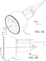
FIG. 4A is a front pictorial view of the nacelle and engine with the translating turning vanes segment in a partially deployed position; -
FIG. 4B is a side view of the nacelle and engine with the cascade of translating turning vanes in a partially deployed position; -
FIG. 4C is a rear pictorial view of the nacelle and engine with the cascade of translating turning vanes in a partially deployed position; -
FIG. 4D is a detailed side section view showing features of the translating turning vanes segment in a partially deployed position; -
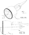
FIG. 5A is a front pictorial view of the inlet nacelle and engine with the cascade of translating turning vanes in a fully deployed position; -
FIG. 5B is a side view of the nacelle and engine with the cascade of translating turning vanes in a fully deployed position; -
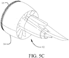
FIG. 5C is a rear pictorial view of the nacelle and engine with the cascade of translating turning vanes in a fully deployed position; -
FIG. 6 is a front view of the turbofan engine as mounted on the wing adjacent the fuselage with the cascade of translating turning vanes in a fully deployed position; -
FIG. 7 is a flow chart depicting a method for flow control in a turbofan engine having a short inlet. - The exemplary embodiments described herein provide translating multiple element turning vanes for adverse flow conditions in an ultra-short nacelle inlet to solve the problem of flow distortion on the fan face of the engine. The multiple element turning vanes are a deployable aerodynamic structure having a vane cascade with varying airfoil sections which are extended from the leading edge of the nacelle to decrease or eliminate flow separation from the inlet inner contour in off-nominal conditions such as crosswind and high angles of attack. The resulting variable geometry inlet deals with low speed and high angle of attack problems of separated flow, while still preserving the short nacelle by retracting into a recess in the nacelle leading edge to maintain cruise performance and the overall optimum performance of the larger engine.
- Referring to the drawings,
FIG. 1 depicts a largecommercial aircraft 10 employing high bypassratio turbofan engines 12 havingultra-short nacelles 14. Aradial cascade 15 of translating turning vanes are configured to be deployed around a leadingedge 18 of thenacelle 14 in translatingturning vane segments 16 as seen inFIG. 2A .The leadingedge 18 circumscribes aninlet 13 providing air flow into thenacelle 14 for theturbofan engine 12. Thecascade 15 of extendible turning vanes translates to be positionable over a range from a stowed or retracted position as seen inFIGs. 3A-3D to the fully deployed or extended position seen inFIG. 2A and in detail inFIGs. 2B and2C . Thecascade 15 of extendible turning vanes provides a flow control system to reduce flow distortion in the inlet. - Each translating turning
vane segment 16 has anose vane 17a, and multiple trailingvanes longitudinal ribs 19. Thenose vane 17a has anouter contour 20 matching the nose contour of the leadingedge 18, whereby in the retracted position, laminar flow of the inlet may be substantially maintained. Aclosing vane 17f again has anouter contour 21 matching the contour of the leadingedge 18 to provide a smooth aerodynamic transition with the translating turningvane segment 16 in the fully extended position aligning theclosing vane 17f with the leadingedge 18. - While shown in the drawings as having a common shape,
vanes 17b-17e may have differing airfoil shapes and chord for tailoring the aerodynamics of flow turning as required. As seen inFIG. 2B , theradial cascade 15 of extendable translating turningvane segments 16 has fully extendedlength 22 which is determined based on the number and spacing ofvanes 17a-17e but is nominally 2.5-20% of thenacelle length 24. For the embodiment shown, thenose vane 17a and fouradditional vanes 17b-17e are used. In alternative embodiments between 2 and 10 vanes may be employed. -
FIGs. 2D-2E show the translating turningvane segment 16 in alternate views for clarity. The entireradial cascade 15 may be a single element which is extended from the leadingedge 18 as a unit or cartridge with acontinuous nose vane 17a. Alternatively, theradial cascade 15 may be split into quadrants, individually operable to extend translating turningvane segments 16 or other desired segments spanning a portion of the circumference of the leadingedge 18 for operational sequencing as will be described in greater detail subsequently. For simplicity in explanation, the description is provided herein in terms of an individual translating turningvane segment 16. - The
ribs 19 support thevanes 17a - 17e to provide spacing of flow channels orslots 26a - 26e between the vanes. Deployment of the translating turningvane segments 16 increases the effective chord of the nacelle. - As seen in
FIGs. 2C and3D , theribs 19 are supported by a plurality ofbearings 28 for longitudinal extension from and retraction into thenacelle 14. A plurality of actuators such asrollers 30, which may be pinion gears engaging a gear rack in theribs 19, are engaged to extend or retract the translating turningvane segments 16 in thecascade 15. Stepper motors or similar devices may be employed to drive the pinion gears for precise extension length for partial and full extension. In alternative embodiments, linear actuators may be employed to extend and retract the translating turningvane segments 16. Depending on the selected configuration of the cascade 15 (a single cartridge, individual translating turning vane segments or partial circumferential segments)multiple vane segments 16 may be interconnected by mechanical or hydraulic linkages and the number of individual ribs or segments driven by separate actuators may vary. In certain embodiments a single actuator may be employed to extend theentire cascade 15. In certain embodiments, one or more of thevanes 17a-17e in the translating turningvane segments 16 may be rotatable about an axis 23 (represented inFIG. 2C ). - For the embodiment shown, the outer extent of a slotted
opening 32 in the leading edge 18 (best seen inFIGs. 2D and2E ), through which thecascade 15 is extended and retracted, has anouter edge 34 relative to a nacelle inlet centerline 36 (seen inFIG. 2C ) substantially aligned with a nominal cruisecondition stagnation point 38 on thenacelle leading edge 18. Thecascade 15 is thus positioned radially inward from thestagnation point 38 to avoid interrupting flow on the exterior contour of thenacelle 14 for reduced drag at cruise. Matching of theouter contour 20 of thenose vane 17a to the contour of the leading edge of the nacelle reduces flow disruption on the internal surface of the inlet with thecascade 15 retracted for cruise conditions to minimize aerodynamic drag at cruise. The slottedopening 32 opens into arecess 33 in thenacelle 14 to house thecascade 15. - Deployment of the cascade of translating turning
vane segments 16 is demonstrated in the sequence of drawings inFIGs. 3A-3C (closed or retracted),FIGs. 4A-4C (partially extended) andFIGs. 5A-5C (fully extended). Exemplary embodiments will typically be operated at either the stowed/retracted or fully extended positions. However, in alternative embodiments, multiple partially extended positions may be employed, exposing differing numbers of vanes and slots to match aerodynamic operating requirements. As displayed in this sequence, extension of the entireradial cascade 15 of translating turningvane segments 16 is symmetrical about thenacelle inlet centerline 36. - As seen in
FIG. 4D , the partially extended translating turningvane segment 16 provides an intermediate chord extension for thenacelle 14.Intermediate vane 17d has a contour comparable to theouter contour 21 ofclosing vane 17f to provide flow smoothing around and substantially close theslot 32 in the nacelle leading edge with the segment in the partially extended position. -
FIG. 6 shows the symmetrical extended configuration of theradial cascade 15 of translating turningvane segments 16. As annotated inFIG. 6 ,quadrants 40a-40d around the nacelle may have differing aerodynamic conditions or effects created by angle of attack of the aircraft as a whole, cross winds, which may be partially shielded or mitigated by thefuselage 42 of the aircraft, or other aerodynamic phenomenon induced during flight, takeoff or landing of the aircraft. Each of the translating turningvane segments 16 may be separately operable for extension and retraction. For high angle of attack operation of the aircraft, deployment of selectable groups of the translating turningvane segments 16 in at least lower outboard and lowerinboard quadrants outboard quadrants inboard quadrants fuselage 42 may block left cross wind flow and deployment of the translating turning vane segments in upperinboard quadrant 40c may not be required. The descriptions herein are reversed for left and right designations for an engine mounted on the left side of the aircraft. Additionally, while shown in the drawings as equal quadrants, the "quadrants" may be interpreted as any selected arcuate segments of the circumference of the inlet. - For aircraft with certain operating conditions or engine mounting configurations, the cascade of translating turning vane segments may be altered to include only active devices in
lower quadrants quadrants - The embodiments disclosed herein provide a method for inlet flow control on an ultra-short turbofan engine nacelle as shown in
FIG. 7 . For a first predetermined aerodynamic condition, thecascade 15 of translating turningvane segments 16 may be extended to a partially extended position,step 702. For a second predetermined aerodynamic condition, thecascade 15 of translating turningvane segments 16 is fully extended,step 704. For an expected predetermined high angle of attack condition a plurality of translating turningvane segments 16 on each engine may be extended in at leastlower quadrants edge 18 of the inlet, step 706. With a predetermined outboard cross wind component a plurality of translating turningvanes segments 16 may be extended in at least theoutboard quadrants step 708. For a predetermined inboard cross wind component a plurality of translating turningvane segments 16 may be extended in at least theinboard quadrants step 710, or where fuselage blocking or mitigation of the inboard cross wind is anticipated, translating turningvane segments 16 in the upper inboard quadrant may remain retracted and only translating turningvanes segments 16 in the lower inboard quadrant are extended,step 712. Upon exceeding a predetermined flight speed and/or reducing operation to a lower angle of attack, all translating turningvane segments 16 are retracted,step 714. - Further, the disclosure comprises embodiments according to the following clauses:
- 1. A flow control system on an aircraft engine nacelle, the system comprising:
- a cascade (15) of translating turning vanes (17a-17e) configured to be extended from a leading edge (18) of a nacelle (14); and
- at least one actuator (30) coupled to the cascade of translating turning vanes to translate the cascade of translating turning vanes from a retracted position to an extended position and from the extended position to the retracted position.
- 2. The flow control system as defined in clause 1 wherein the cascade of translating turning vanes are engaged by a plurality of longitudinal ribs (19) forming translating turning vane segments (16).
- 3. The flow control system as defined in clause 1 wherein the cascade of translating turning vanes comprises between 2 and 10 vanes (17a-17e).
- 4. The flow control system as defined in clause 1 wherein the cascade of translating turning vanes includes a nose vane (17a) having an outer contour (20) matching a contour of the leading edge of the nacelle.
- 5. The flow control system as defined in clause 1 wherein the cascade is translated through a slotted opening (32) in the leading edge of the nacelle, the slot opening having an outer edge (34) located at or inboard from a cruise condition stagnation point (38) relative to a nacelle inlet centerline (36).
- 6. The flow control system as defined in clause 1 wherein the cascade of translating turning vanes includes a closing vane (17f) having an outer contour matching a contour of the leading edge of the nacelle, said closing vane being aligned with the outer contour when in the extended position.
- 7. The flow control system as defined in clause 1 wherein a length of the cascade of translating turning vanes in the extended position is between about 2.5% to 20% of a nacelle length.
- 8. The flow control system as defined in
clause 2 wherein each translating turning vanes segment of the cascade of translating turning vanes is separately translatable. - 9. The flow control system as defined in clause 8 wherein the at least one actuator comprises a plurality of actuators engaged to translate associated translating turning vane segments.
- 10. The flow control system as defined in clause 9 wherein selectable groups of the translating turning vane segments are simultaneously extendible.
- 11. The flow control system as defined in
clause 10 wherein at least one of the selectable groups is located in a lower quadrant (54a, 54b) of a circumference of a nacelle inlet, wherein the at least one of the selectable groups is adapted to accommodate a high angle of attack of the nacelle inlet. - 12. The flow control system as defined in
clause 10 wherein at least two of the selectable groups are located in outboard quadrants (54a, 54d) of a circumference of a nacelle inlet, wherein the at least two of the selectable groups are adapted to accommodate outboard crosswinds at the nacelle inlet. - 13. The flow control system as defined in
clause 10 wherein at least one of the selectable groups is located in an inboard quadrant (54b, 54c) of a circumference of a nacelle inlet, wherein the at least one of the selectable groups is adapted to accommodate inboard crosswinds at the nacelle inlet. - 14. The flow control system as defined in clause 1 wherein the cascade (15) of translating turning vanes (17a-17e) is configured to be extended to multiple partially extended positions.
- 15. A method for inlet flow control on an engine nacelle comprising:
extending a cascade of translating turning vanes on the engine nacelle by translating the cascade through a slot in a leading edge of a nacelle inlet. - 16. The method of
clause 15 wherein the cascade of translating turning vanes is extended in at least one lower quadrant of a nacelle inlet circumference accommodating a high angle of attack of the engine nacelle. - 17. The method of
clause 16 further comprising extending a plurality of translating turning vanes segments in at least one outboard quadrant of the nacelle inlet circumference accommodating a predetermined outboard wind component. - 18. The method of
clause 16 further comprising extending a plurality of translating turning vanes segments in at least one inboard quadrant of the nacelle inlet circumference accommodating a predetermined inboard wind component. - 19. The method of
clause 16 further comprising extending a plurality of translating turning vanes segments in a lower inboard quadrant of the nacelle inlet circumference accommodating a predetermined inboard wind component with a plurality of translating turning vanes segments in an upper inboard quadrant remaining retracted. - 20. The method of
clause 16 further comprising retracting all translating turning vanes upon exceeding a predetermined speed or operation of the engine nacelle at a lower angle of attack. - 21. An aircraft engine nacelle comprising:
- a leading edge (18) of a nacelle (14) defining an inlet opening (13) for air flow into an engine (12) housed in the nacelle; and
- a flow control system located on the leading edge, the system comprising:
- a cascade (15) of translating turning vanes (17a-17e) arranged about a circumference of the leading edge, the cascade of translating turning vanes being movable between a stowed position and an extended position in which the cascade of translating turning vanes extend forward from the leading edge of the nacelle; and
- at least one actuator (30) coupled to translate the cascade of translating turning vanes between the stowed position and the extended position.
- 22. The aircraft engine nacelle of
clause 21, wherein the cascade of translating turning vanes are housed in a recess (33) formed in the nacelle when the translating turning vanes are moved to the stowed position. - Having now described various embodiments of the disclosure in detail as required by the patent statutes, those skilled in the art will recognize modifications and substitutions to the specific embodiments disclosed herein. Such modifications are within the scope and intent of the present disclosure as defined in the following claims.
Claims (15)
- A flow control system on an aircraft engine nacelle, the system comprising:a cascade (15) of translating turning vanes (17a-17e) configured to extend from a leading edge (18) of a nacelle (14); andat least one actuator (30) coupled to translate the cascade of translating turning vanes from a retracted position to an extended position.
- The flow control system as defined in claim 1 wherein the cascade of translating turning vanes are engaged by a plurality of longitudinal ribs (19) forming translating turning vane segments (16).
- The flow control system as defined in claim 1 or 2 wherein:the cascade of translating turning vanes comprises between 2 and 10 vanes (17a-17e); and/orthe cascade of translating turning vanes includes a nose vane (17a) having an outer contour (20) matching a contour of the leading edge of the nacelle.
- The flow control system as defined in any preceding claim wherein the cascade is translated through a slotted opening (32) in the leading edge of the nacelle, the slot opening having an outer edge (34) located at or inboard from a cruise condition stagnation point (38) relative to a nacelle inlet centerline (36).
- The flow control system as defined in any preceding claim wherein the cascade of translating turning vanes includes a closing vane (17f) having an outer contour matching a contour of the leading edge of the nacelle, said closing vane being aligned with the outer contour when in the extended position.
- The flow control system as defined in any preceding claim wherein a length of the cascade of translating turning vanes in the extended position comprises between about 2.5% to 20% of a nacelle length.
- The flow control system as defined in claim 2 wherein each translating turning vanes segment of the cascade of translating turning vanes is separately translatable, optionally wherein the at least one actuator comprises a plurality of actuators engaged to translate associated translating turning vane segments, and optionally wherein selectable groups of the translating turning vane segments are simultaneously extendible.
- The flow control system as defined in claim 7 wherein at least one of the selectable groups is located in a lower quadrant (54a, 54b) of a circumference of a nacelle inlet, wherein the at least one of the selectable groups is adapted to accommodate a high angle of attack of the nacelle inlet.
- The flow control system as defined in claim 7 or 8 wherein at least two of the selectable groups are located in outboard quadrants (54a, 54d) of a circumference of a nacelle inlet, wherein the at least two of the selectable groups are adapted to accommodate outboard crosswinds at the nacelle inlet.
- The flow control system as defined in any one of claims 7 to 9 wherein at least one of the selectable groups is located in an inboard quadrant (54b, 54c) of a circumference of a nacelle inlet, wherein the at least one of the selectable groups is adapted to accommodate inboard crosswinds at the nacelle inlet.
- A method for inlet flow control on an engine nacelle comprising:
extending a cascade of translating turning vanes on the engine nacelle by translating the cascade through a slot in a leading edge of a nacelle inlet in at least one lower quadrant of a nacelle inlet circumference accommodating a high angle of attack of the engine nacelle. - The method of claim 11 further comprising extending a plurality of translating turning vane segments in at least one outboard quadrant of the nacelle inlet circumference accommodating a predetermined outboard wind component.
- The method of claim 11 or 12 further comprising extending a plurality of translating turning vane segments in at least one inboard quadrant of the nacelle inlet circumference accommodating a predetermined inboard wind component.
- The method of any one of claims 11 to 13 further comprising extending a plurality of translating turning vane segments in a lower inboard quadrant of the nacelle inlet circumference accommodating a predetermined inboard wind component with a plurality of translating turning vanes segments in an upper inboard quadrant remaining retracted.
- The method of any one of claims 11 to 14 further comprising retracting all translating turning vanes upon exceeding a predetermined speed or operation of the engine nacelle at a lower angle of attack.
Applications Claiming Priority (1)
| Application Number | Priority Date | Filing Date | Title |
|---|---|---|---|
| US15/633,579 US10436112B2 (en) | 2017-06-26 | 2017-06-26 | Translating turning vanes for a nacelle inlet |
Publications (2)
| Publication Number | Publication Date |
|---|---|
| EP3421370A1 true EP3421370A1 (en) | 2019-01-02 |
| EP3421370B1 EP3421370B1 (en) | 2025-03-12 |
Family
ID=62791611
Family Applications (1)
| Application Number | Title | Priority Date | Filing Date |
|---|---|---|---|
| EP18179867.9A Active EP3421370B1 (en) | 2017-06-26 | 2018-06-26 | Translating turning vanes for a nacelle inlet |
Country Status (3)
| Country | Link |
|---|---|
| US (1) | US10436112B2 (en) |
| EP (1) | EP3421370B1 (en) |
| CN (1) | CN109113797B (en) |
Families Citing this family (11)
| Publication number | Priority date | Publication date | Assignee | Title |
|---|---|---|---|---|
| US11125157B2 (en) | 2017-09-22 | 2021-09-21 | The Boeing Company | Advanced inlet design |
| US10974813B2 (en) * | 2018-01-08 | 2021-04-13 | General Electric Company | Engine nacelle for an aircraft |
| US11390393B2 (en) | 2019-06-04 | 2022-07-19 | Rohr, Inc. | Nacelle with a translatable inlet for an aircraft propulsion system |
| FR3101854B1 (en) * | 2019-10-15 | 2024-05-31 | Inst Superieur De L Aeronautique Et De L Espace | TURBOMACHINE NACELLE |
| US11828237B2 (en) * | 2020-04-28 | 2023-11-28 | General Electric Company | Methods and apparatus to control air flow separation of an engine |
| FR3114615B1 (en) * | 2020-09-30 | 2024-01-12 | Safran Aircraft Engines | AIR INLET HANDLE FILTERING DISTORTION FOR A NACELLE OF AN AIRCRAFT PROPULSION ASSEMBLY |
| BR102022003769A2 (en) | 2021-05-04 | 2022-11-16 | The Boeing Company | NACELE ENTRY STRUCTURE OF AN ENGINE ASSEMBLY |
| US11560841B2 (en) | 2021-06-25 | 2023-01-24 | Rohr, Inc. | Aircraft propulsion system with variable area inlet |
| US11725581B2 (en) | 2021-06-25 | 2023-08-15 | Rohr, Inc. | Aircraft propulsion system with variable area inlet |
| US11767124B2 (en) | 2021-09-10 | 2023-09-26 | Rohr, Inc. | Aircraft propulsion system with variable area inlet |
| US11840985B2 (en) | 2021-09-10 | 2023-12-12 | Rohr, Inc. | Aircraft propulsion system with variable area inlet |
Citations (3)
| Publication number | Priority date | Publication date | Assignee | Title |
|---|---|---|---|---|
| US3532129A (en) * | 1969-02-05 | 1970-10-06 | Rolls Royce | Silencing of gas turbine engines |
| EP2003310A2 (en) * | 2007-06-15 | 2008-12-17 | United Technologies Corporation | Variable geometry nacelle for an aircraft engine |
| US20090092482A1 (en) * | 2007-10-09 | 2009-04-09 | United Technologies Corp. | Systems and Methods for Altering Inlet Airflow of Gas Turbine Engines |
Family Cites Families (34)
| Publication number | Priority date | Publication date | Assignee | Title |
|---|---|---|---|---|
| US3222863A (en) * | 1963-10-07 | 1965-12-14 | Boeing Co | Aerodynamic inlet |
| US3664612A (en) * | 1969-12-22 | 1972-05-23 | Boeing Co | Aircraft engine variable highlight inlet |
| US3618876A (en) * | 1969-12-22 | 1971-11-09 | Boeing Co | Aircraft engine leading edge auxiliary air inlet |
| US3883095A (en) * | 1973-09-19 | 1975-05-13 | Nasa | Reversed cowl flap inlet thrust augmentor |
| US4804155A (en) * | 1987-03-02 | 1989-02-14 | Strumbos William P | VTOL aircraft |
| DE3720318A1 (en) * | 1987-06-19 | 1989-01-05 | Mtu Muenchen Gmbh | GONDOLA FOR JET ENGINES |
| US5257498A (en) * | 1992-04-23 | 1993-11-02 | United Technologies Corporation | Efficient anti-ice exhaust vent |
| US6089505A (en) * | 1997-07-22 | 2000-07-18 | Mcdonnell Douglas Corporation | Mission adaptive inlet |
| US6655632B1 (en) | 2002-08-27 | 2003-12-02 | General Electric Company | System and method for actively changing an effective flow-through area of an inlet region of an aircraft engine |
| US6910327B2 (en) * | 2003-07-28 | 2005-06-28 | The Boeing Company | Apparatus and methods for varying inlet lip geometry of a jet engine inlet |
| FR2914363B1 (en) * | 2007-03-26 | 2012-07-27 | Aircelle Sa | LOCKABLE GUIDE SYSTEM FOR MOBILE PART OF A NACELLE |
| US8408491B2 (en) * | 2007-04-24 | 2013-04-02 | United Technologies Corporation | Nacelle assembly having inlet airfoil for a gas turbine engine |
| US20130019585A1 (en) * | 2007-05-11 | 2013-01-24 | Brian Merry | Variable fan inlet guide vane for turbine engine |
| US8402739B2 (en) * | 2007-06-28 | 2013-03-26 | United Technologies Corporation | Variable shape inlet section for a nacelle assembly of a gas turbine engine |
| FR2925607B1 (en) * | 2007-12-21 | 2013-05-10 | Aircelle Sa | NACELLE FOR AIRCRAFT ENGINE WITH VARIABLE SECTION TUBE |
| FR2925877B1 (en) * | 2007-12-26 | 2009-12-04 | Aircelle Sa | INSTALLATION OF GUIDING SYSTEM ON AN AIRCRAFT NACELLE. |
| FR2927609B1 (en) * | 2008-02-18 | 2010-06-25 | Aircelle Sa | AIR INTAKE FOR AIRCRAFT NACELLE, AND NACELLE EQUIPPED WITH SUCH AIR INTAKE |
| FR2933143B1 (en) * | 2008-06-26 | 2011-06-10 | Airbus France | NACELLE FOR AN AIRCRAFT COMPRISING INVERTER PUSHING MEANS AND AIRCRAFT COMPRISING AT LEAST ONE SUCH NACELLE |
| US8109467B2 (en) * | 2009-04-24 | 2012-02-07 | United Technologies Corporation | Thrust reverser assembly with shaped drag links |
| FR2959532B1 (en) * | 2010-04-30 | 2013-01-04 | Aircelle Sa | TURBOREACTOR NACELLE |
| US8974177B2 (en) * | 2010-09-28 | 2015-03-10 | United Technologies Corporation | Nacelle with porous surfaces |
| DE102011101342A1 (en) * | 2011-05-12 | 2012-11-15 | Rolls-Royce Deutschland Ltd & Co Kg | Air turbine engine with oil cooler in the engine cowling |
| FR2978990A1 (en) * | 2011-08-08 | 2013-02-15 | Aircelle Sa | PUSH REVERSING DEVICE |
| FR2981989B1 (en) * | 2011-10-31 | 2013-11-01 | Aircelle Sa | MOBILE SCREW REVERSE INVERTER AND MONOBLOC MOBILE HOOD |
| US9255546B2 (en) * | 2012-02-02 | 2016-02-09 | Spirit AreoSystems, Inc. | Cascade-style variable area fan duct nozzle |
| US9016040B2 (en) * | 2012-11-30 | 2015-04-28 | General Electric Company | Thrust reverser system with translating-rotating cascade and method of operation |
| FR3002785B1 (en) * | 2013-03-01 | 2015-03-27 | Aircelle Sa | TRANSLATANT AND FIXED GRIDS WITH A T / R O-DUCT. |
| EP3047133A4 (en) * | 2013-09-19 | 2017-05-10 | United Technologies Corporation | Extended thrust reverser cascade |
| US9810147B2 (en) * | 2013-10-31 | 2017-11-07 | The Boeing Company | Angled inlet system for a precooler |
| CN104691741B (en) * | 2013-12-06 | 2017-11-10 | 中国航发商用航空发动机有限责任公司 | Aero-engine nacelle |
| US9719466B2 (en) * | 2014-09-17 | 2017-08-01 | The Boeing Company | System and method for improved thrust reverser with increased reverse thrust and reduced noise |
| US20160305370A1 (en) * | 2015-04-16 | 2016-10-20 | Honeywell International Inc. | Translating cowl thrust reverser with door pivots aft of reverse flow path |
| US10041443B2 (en) * | 2015-06-09 | 2018-08-07 | The Boeing Company | Thrust reverser apparatus and method |
| US10399687B2 (en) * | 2015-12-03 | 2019-09-03 | The Boeing Company | Methods and apparatus to vary an air intake of aircraft engines |
-
2017
- 2017-06-26 US US15/633,579 patent/US10436112B2/en active Active
-
2018
- 2018-06-06 CN CN201810573592.4A patent/CN109113797B/en active Active
- 2018-06-26 EP EP18179867.9A patent/EP3421370B1/en active Active
Patent Citations (3)
| Publication number | Priority date | Publication date | Assignee | Title |
|---|---|---|---|---|
| US3532129A (en) * | 1969-02-05 | 1970-10-06 | Rolls Royce | Silencing of gas turbine engines |
| EP2003310A2 (en) * | 2007-06-15 | 2008-12-17 | United Technologies Corporation | Variable geometry nacelle for an aircraft engine |
| US20090092482A1 (en) * | 2007-10-09 | 2009-04-09 | United Technologies Corp. | Systems and Methods for Altering Inlet Airflow of Gas Turbine Engines |
Also Published As
| Publication number | Publication date |
|---|---|
| US20180371996A1 (en) | 2018-12-27 |
| US10436112B2 (en) | 2019-10-08 |
| CN109113797B (en) | 2022-06-28 |
| EP3421370B1 (en) | 2025-03-12 |
| CN109113797A (en) | 2019-01-01 |
Similar Documents
| Publication | Publication Date | Title |
|---|---|---|
| US10436112B2 (en) | Translating turning vanes for a nacelle inlet | |
| CA3003031C (en) | Rotating devices for mitigation of adverse flow conditions in an ultra-short nacelle inlet | |
| EP2552775B1 (en) | Low noise wing slat system with deployable wing leading edge elements | |
| CN107878733B (en) | Translating fan blades for aircraft tail mounted fan assemblies | |
| EP2060770B1 (en) | Thrust reverser door | |
| EP2410165B1 (en) | Gas turbine with noise attenuating variable area fan nozzle | |
| US9481449B2 (en) | Blade, particularly variable-pitch blade, propellor comprising such blades and corresponding turbomachine | |
| EP3144215B1 (en) | Non-axis symmetric aft engine | |
| EP3144216A1 (en) | Aft engine for an aircraft | |
| US10252791B2 (en) | Deployable assembly for a propulsor | |
| US20160327073A1 (en) | Dynamically controllable force-generating system | |
| CN109751284B (en) | Fan shroud with serrated trailing edge providing attached flow in reverse thrust mode | |
| BR102016020094B1 (en) | AIRCRAFT | |
| US11878786B2 (en) | Propulsion system for an aircraft | |
| US11820509B2 (en) | Retractable duct channel wing | |
| US11873096B1 (en) | Aircraft wing and propulsion system | |
| CN120826351A (en) | Pop-up spoiler | |
| CN118391139A (en) | Variable geometry inlet for turboprop inlet pressure recovery optimization | |
| US20190210710A1 (en) | Engine nacelle for an aircraft | |
| US9650992B2 (en) | Core cowl thrust reverser system and apparatus | |
| US12442333B1 (en) | Turbine engine having a variable engine intake system | |
| US12529335B1 (en) | Turbine engine having a variable engine intake system | |
| US12435666B1 (en) | Turbine engine having a variable engine intake system | |
| US20260126005A1 (en) | Turbine engine having a variable engine intake system |
Legal Events
| Date | Code | Title | Description |
|---|---|---|---|
| PUAI | Public reference made under article 153(3) epc to a published international application that has entered the european phase |
Free format text: ORIGINAL CODE: 0009012 |
|
| STAA | Information on the status of an ep patent application or granted ep patent |
Free format text: STATUS: REQUEST FOR EXAMINATION WAS MADE |
|
| 17P | Request for examination filed |
Effective date: 20180626 |
|
| AK | Designated contracting states |
Kind code of ref document: A1 Designated state(s): AL AT BE BG CH CY CZ DE DK EE ES FI FR GB GR HR HU IE IS IT LI LT LU LV MC MK MT NL NO PL PT RO RS SE SI SK SM TR |
|
| AX | Request for extension of the european patent |
Extension state: BA ME |
|
| STAA | Information on the status of an ep patent application or granted ep patent |
Free format text: STATUS: EXAMINATION IS IN PROGRESS |
|
| 17Q | First examination report despatched |
Effective date: 20211119 |
|
| RAP3 | Party data changed (applicant data changed or rights of an application transferred) |
Owner name: THE BOEING COMPANY |
|
| GRAP | Despatch of communication of intention to grant a patent |
Free format text: ORIGINAL CODE: EPIDOSNIGR1 |
|
| STAA | Information on the status of an ep patent application or granted ep patent |
Free format text: STATUS: GRANT OF PATENT IS INTENDED |
|
| INTG | Intention to grant announced |
Effective date: 20241001 |
|
| GRAS | Grant fee paid |
Free format text: ORIGINAL CODE: EPIDOSNIGR3 |
|
| GRAA | (expected) grant |
Free format text: ORIGINAL CODE: 0009210 |
|
| STAA | Information on the status of an ep patent application or granted ep patent |
Free format text: STATUS: THE PATENT HAS BEEN GRANTED |
|
| AK | Designated contracting states |
Kind code of ref document: B1 Designated state(s): AL AT BE BG CH CY CZ DE DK EE ES FI FR GB GR HR HU IE IS IT LI LT LU LV MC MK MT NL NO PL PT RO RS SE SI SK SM TR |
|
| REG | Reference to a national code |
Ref country code: GB Ref legal event code: FG4D |
|
| REG | Reference to a national code |
Ref country code: CH Ref legal event code: EP |
|
| P01 | Opt-out of the competence of the unified patent court (upc) registered |
Free format text: CASE NUMBER: APP_7818/2025 Effective date: 20250214 |
|
| REG | Reference to a national code |
Ref country code: DE Ref legal event code: R096 Ref document number: 602018079999 Country of ref document: DE |
|
| REG | Reference to a national code |
Ref country code: IE Ref legal event code: FG4D |
|
| PG25 | Lapsed in a contracting state [announced via postgrant information from national office to epo] |
Ref country code: RS Free format text: LAPSE BECAUSE OF FAILURE TO SUBMIT A TRANSLATION OF THE DESCRIPTION OR TO PAY THE FEE WITHIN THE PRESCRIBED TIME-LIMIT Effective date: 20250612 |
|
| PG25 | Lapsed in a contracting state [announced via postgrant information from national office to epo] |
Ref country code: FI Free format text: LAPSE BECAUSE OF FAILURE TO SUBMIT A TRANSLATION OF THE DESCRIPTION OR TO PAY THE FEE WITHIN THE PRESCRIBED TIME-LIMIT Effective date: 20250312 |
|
| PGFP | Annual fee paid to national office [announced via postgrant information from national office to epo] |
Ref country code: DE Payment date: 20250627 Year of fee payment: 8 |
|
| PG25 | Lapsed in a contracting state [announced via postgrant information from national office to epo] |
Ref country code: ES Free format text: LAPSE BECAUSE OF FAILURE TO SUBMIT A TRANSLATION OF THE DESCRIPTION OR TO PAY THE FEE WITHIN THE PRESCRIBED TIME-LIMIT Effective date: 20250312 |
|
| PGFP | Annual fee paid to national office [announced via postgrant information from national office to epo] |
Ref country code: GB Payment date: 20250627 Year of fee payment: 8 |
|
| REG | Reference to a national code |
Ref country code: LT Ref legal event code: MG9D |
|
| PG25 | Lapsed in a contracting state [announced via postgrant information from national office to epo] |
Ref country code: NO Free format text: LAPSE BECAUSE OF FAILURE TO SUBMIT A TRANSLATION OF THE DESCRIPTION OR TO PAY THE FEE WITHIN THE PRESCRIBED TIME-LIMIT Effective date: 20250612 |
|
| PG25 | Lapsed in a contracting state [announced via postgrant information from national office to epo] |
Ref country code: HR Free format text: LAPSE BECAUSE OF FAILURE TO SUBMIT A TRANSLATION OF THE DESCRIPTION OR TO PAY THE FEE WITHIN THE PRESCRIBED TIME-LIMIT Effective date: 20250312 |
|
| REG | Reference to a national code |
Ref country code: NL Ref legal event code: MP Effective date: 20250312 |
|
| PG25 | Lapsed in a contracting state [announced via postgrant information from national office to epo] |
Ref country code: LV Free format text: LAPSE BECAUSE OF FAILURE TO SUBMIT A TRANSLATION OF THE DESCRIPTION OR TO PAY THE FEE WITHIN THE PRESCRIBED TIME-LIMIT Effective date: 20250312 |
|
| PGFP | Annual fee paid to national office [announced via postgrant information from national office to epo] |
Ref country code: FR Payment date: 20250625 Year of fee payment: 8 |
|
| PG25 | Lapsed in a contracting state [announced via postgrant information from national office to epo] |
Ref country code: GR Free format text: LAPSE BECAUSE OF FAILURE TO SUBMIT A TRANSLATION OF THE DESCRIPTION OR TO PAY THE FEE WITHIN THE PRESCRIBED TIME-LIMIT Effective date: 20250613 Ref country code: BG Free format text: LAPSE BECAUSE OF FAILURE TO SUBMIT A TRANSLATION OF THE DESCRIPTION OR TO PAY THE FEE WITHIN THE PRESCRIBED TIME-LIMIT Effective date: 20250312 |
|
| REG | Reference to a national code |
Ref country code: AT Ref legal event code: MK05 Ref document number: 1774854 Country of ref document: AT Kind code of ref document: T Effective date: 20250312 |
|
| PG25 | Lapsed in a contracting state [announced via postgrant information from national office to epo] |
Ref country code: NL Free format text: LAPSE BECAUSE OF FAILURE TO SUBMIT A TRANSLATION OF THE DESCRIPTION OR TO PAY THE FEE WITHIN THE PRESCRIBED TIME-LIMIT Effective date: 20250312 |
|
| PG25 | Lapsed in a contracting state [announced via postgrant information from national office to epo] |
Ref country code: SE Free format text: LAPSE BECAUSE OF FAILURE TO SUBMIT A TRANSLATION OF THE DESCRIPTION OR TO PAY THE FEE WITHIN THE PRESCRIBED TIME-LIMIT Effective date: 20250312 |
|
| PG25 | Lapsed in a contracting state [announced via postgrant information from national office to epo] |
Ref country code: SM Free format text: LAPSE BECAUSE OF FAILURE TO SUBMIT A TRANSLATION OF THE DESCRIPTION OR TO PAY THE FEE WITHIN THE PRESCRIBED TIME-LIMIT Effective date: 20250312 |
|
| PG25 | Lapsed in a contracting state [announced via postgrant information from national office to epo] |
Ref country code: PT Free format text: LAPSE BECAUSE OF FAILURE TO SUBMIT A TRANSLATION OF THE DESCRIPTION OR TO PAY THE FEE WITHIN THE PRESCRIBED TIME-LIMIT Effective date: 20250714 |
|
| PG25 | Lapsed in a contracting state [announced via postgrant information from national office to epo] |
Ref country code: PL Free format text: LAPSE BECAUSE OF FAILURE TO SUBMIT A TRANSLATION OF THE DESCRIPTION OR TO PAY THE FEE WITHIN THE PRESCRIBED TIME-LIMIT Effective date: 20250312 Ref country code: IT Free format text: LAPSE BECAUSE OF FAILURE TO SUBMIT A TRANSLATION OF THE DESCRIPTION OR TO PAY THE FEE WITHIN THE PRESCRIBED TIME-LIMIT Effective date: 20250312 |
|
| PG25 | Lapsed in a contracting state [announced via postgrant information from national office to epo] |
Ref country code: AT Free format text: LAPSE BECAUSE OF FAILURE TO SUBMIT A TRANSLATION OF THE DESCRIPTION OR TO PAY THE FEE WITHIN THE PRESCRIBED TIME-LIMIT Effective date: 20250312 |
|
| PG25 | Lapsed in a contracting state [announced via postgrant information from national office to epo] |
Ref country code: EE Free format text: LAPSE BECAUSE OF FAILURE TO SUBMIT A TRANSLATION OF THE DESCRIPTION OR TO PAY THE FEE WITHIN THE PRESCRIBED TIME-LIMIT Effective date: 20250312 Ref country code: CZ Free format text: LAPSE BECAUSE OF FAILURE TO SUBMIT A TRANSLATION OF THE DESCRIPTION OR TO PAY THE FEE WITHIN THE PRESCRIBED TIME-LIMIT Effective date: 20250312 |
|
| PG25 | Lapsed in a contracting state [announced via postgrant information from national office to epo] |
Ref country code: RO Free format text: LAPSE BECAUSE OF FAILURE TO SUBMIT A TRANSLATION OF THE DESCRIPTION OR TO PAY THE FEE WITHIN THE PRESCRIBED TIME-LIMIT Effective date: 20250312 |
|
| PG25 | Lapsed in a contracting state [announced via postgrant information from national office to epo] |
Ref country code: SK Free format text: LAPSE BECAUSE OF FAILURE TO SUBMIT A TRANSLATION OF THE DESCRIPTION OR TO PAY THE FEE WITHIN THE PRESCRIBED TIME-LIMIT Effective date: 20250312 |
|
| PG25 | Lapsed in a contracting state [announced via postgrant information from national office to epo] |
Ref country code: IS Free format text: LAPSE BECAUSE OF FAILURE TO SUBMIT A TRANSLATION OF THE DESCRIPTION OR TO PAY THE FEE WITHIN THE PRESCRIBED TIME-LIMIT Effective date: 20250712 |
|
| REG | Reference to a national code |
Ref country code: DE Ref legal event code: R097 Ref document number: 602018079999 Country of ref document: DE |
|
| PG25 | Lapsed in a contracting state [announced via postgrant information from national office to epo] |
Ref country code: DK Free format text: LAPSE BECAUSE OF FAILURE TO SUBMIT A TRANSLATION OF THE DESCRIPTION OR TO PAY THE FEE WITHIN THE PRESCRIBED TIME-LIMIT Effective date: 20250312 |
|
| PLBE | No opposition filed within time limit |
Free format text: ORIGINAL CODE: 0009261 |
|
| STAA | Information on the status of an ep patent application or granted ep patent |
Free format text: STATUS: NO OPPOSITION FILED WITHIN TIME LIMIT |
|
| REG | Reference to a national code |
Ref country code: CH Ref legal event code: L10 Free format text: ST27 STATUS EVENT CODE: U-0-0-L10-L00 (AS PROVIDED BY THE NATIONAL OFFICE) Effective date: 20260121 |
|
| REG | Reference to a national code |
Ref country code: CH Ref legal event code: H13 Free format text: ST27 STATUS EVENT CODE: U-0-0-H10-H13 (AS PROVIDED BY THE NATIONAL OFFICE) Effective date: 20260127 |
|
| PG25 | Lapsed in a contracting state [announced via postgrant information from national office to epo] |
Ref country code: MC Free format text: LAPSE BECAUSE OF FAILURE TO SUBMIT A TRANSLATION OF THE DESCRIPTION OR TO PAY THE FEE WITHIN THE PRESCRIBED TIME-LIMIT Effective date: 20250312 |
|
| PG25 | Lapsed in a contracting state [announced via postgrant information from national office to epo] |
Ref country code: LU Free format text: LAPSE BECAUSE OF NON-PAYMENT OF DUE FEES Effective date: 20250626 |
|
| 26N | No opposition filed |
Effective date: 20251215 |
|
| REG | Reference to a national code |
Ref country code: BE Ref legal event code: MM Effective date: 20250630 |
|
| PG25 | Lapsed in a contracting state [announced via postgrant information from national office to epo] |
Ref country code: IE Free format text: LAPSE BECAUSE OF NON-PAYMENT OF DUE FEES Effective date: 20250626 |
|
| PG25 | Lapsed in a contracting state [announced via postgrant information from national office to epo] |
Ref country code: BE Free format text: LAPSE BECAUSE OF NON-PAYMENT OF DUE FEES Effective date: 20250630 |
|
| PG25 | Lapsed in a contracting state [announced via postgrant information from national office to epo] |
Ref country code: CH Free format text: LAPSE BECAUSE OF NON-PAYMENT OF DUE FEES Effective date: 20250630 |