EP3421356A1 - Aircraft steering - Google Patents
Aircraft steering Download PDFInfo
- Publication number
- EP3421356A1 EP3421356A1 EP18180031.9A EP18180031A EP3421356A1 EP 3421356 A1 EP3421356 A1 EP 3421356A1 EP 18180031 A EP18180031 A EP 18180031A EP 3421356 A1 EP3421356 A1 EP 3421356A1
- Authority
- EP
- European Patent Office
- Prior art keywords
- landing gear
- steering system
- aircraft
- wheel arrangement
- control
- Prior art date
- Legal status (The legal status is an assumption and is not a legal conclusion. Google has not performed a legal analysis and makes no representation as to the accuracy of the status listed.)
- Granted
Links
Images



Classifications
-
- B—PERFORMING OPERATIONS; TRANSPORTING
- B64—AIRCRAFT; AVIATION; COSMONAUTICS
- B64C—AEROPLANES; HELICOPTERS
- B64C25/00—Alighting gear
- B64C25/32—Alighting gear characterised by elements which contact the ground or similar surface
- B64C25/50—Steerable undercarriages; Shimmy-damping
-
- B—PERFORMING OPERATIONS; TRANSPORTING
- B64—AIRCRAFT; AVIATION; COSMONAUTICS
- B64C—AEROPLANES; HELICOPTERS
- B64C25/00—Alighting gear
- B64C25/02—Undercarriages
- B64C25/08—Undercarriages non-fixed, e.g. jettisonable
- B64C25/10—Undercarriages non-fixed, e.g. jettisonable retractable, foldable, or the like
-
- B—PERFORMING OPERATIONS; TRANSPORTING
- B64—AIRCRAFT; AVIATION; COSMONAUTICS
- B64C—AEROPLANES; HELICOPTERS
- B64C25/00—Alighting gear
- B64C25/02—Undercarriages
- B64C25/08—Undercarriages non-fixed, e.g. jettisonable
- B64C25/10—Undercarriages non-fixed, e.g. jettisonable retractable, foldable, or the like
- B64C25/14—Undercarriages non-fixed, e.g. jettisonable retractable, foldable, or the like fore-and-aft
-
- B—PERFORMING OPERATIONS; TRANSPORTING
- B64—AIRCRAFT; AVIATION; COSMONAUTICS
- B64C—AEROPLANES; HELICOPTERS
- B64C25/00—Alighting gear
- B64C25/02—Undercarriages
- B64C25/08—Undercarriages non-fixed, e.g. jettisonable
- B64C25/10—Undercarriages non-fixed, e.g. jettisonable retractable, foldable, or the like
- B64C25/18—Operating mechanisms
- B64C25/26—Control or locking systems therefor
-
- B—PERFORMING OPERATIONS; TRANSPORTING
- B64—AIRCRAFT; AVIATION; COSMONAUTICS
- B64C—AEROPLANES; HELICOPTERS
- B64C25/00—Alighting gear
- B64C25/32—Alighting gear characterised by elements which contact the ground or similar surface
- B64C25/34—Alighting gear characterised by elements which contact the ground or similar surface wheeled type, e.g. multi-wheeled bogies
Definitions
- the present invention relates to aircraft steering systems, and more particularly to apparatus and methods for controlling aircraft steering systems.
- Aircraft often include steering systems to control the direction of movement of the aircraft when the aircraft is moving on the ground ("taxiing").
- steering systems include wheels forming part of a landing gear which is retracted into a landing gear bay after take-off and deployed from the landing gear bay prior to landing the aircraft.
- the aircraft When on the ground, the aircraft is supported by the landing gear and moves by rotation of the landing gear wheels.
- an aircraft includes a nose landing gear located under the aircraft nose and main landing gears located under the aircraft wings.
- the nose landing gear wheels are typically pivotable about a vertical axis to alter the direction of orientation of the nose landing gear wheels, thereby altering the direction of movement of the aircraft.
- the steering system is correctly orientated (e.g. centered) when the aircraft lands, to correspond with the direction of travel of the aircraft at the point of landing. Deviation from the correct orientation may result in an uncomfortable or unsafe aircraft landing.
- procedures for retraction of the landing gear include procedures for centering the nose landing gear prior to storing it in the landing gear bay.
- sensor may detect that the a shock absorber on the landing gear is fully extended, indicating that the landing gear is not bearing the aircraft weight because the aircraft has left the ground, and automatically centre the landing gear wheels in response.
- the landing gear wheels may move away from the centre position due to, for example, equipment malfunction or accidental use of the steering control system during a flight
- some aircraft include components to disable the steering system during the flight period, so as to prevent movement of the wheels.
- some aircraft include a mechanically activated valve, known as a mechanical shut off valve, to isolate hydraulic actuators of the steering system from a source of hydraulic pressure. Such valves may be activated by a link arm or other structure which comes into contact with the valve when the landing gear is retracted.
- a mechanical shut off valve to isolate hydraulic actuators of the steering system from a source of hydraulic pressure.
- Such valves may be activated by a link arm or other structure which comes into contact with
- a first aspect of the invention provides a control apparatus for controlling a steering system of an aircraft landing gear, the aircraft landing gear being configurable in a stowed configuration in which the aircraft landing gear is stowed in a landing gear bay of the aircraft, and a deployed configuration, in which the landing gear is deployed outside of the landing gear bay, the steering system comprising a wheel arrangement including one or more wheels, wherein the control apparatus is arranged to perform a control process comprising: receiving one or more signals from one or more sensors indicating a position of the wheel arrangement when the landing gear is in the stowed configuration; determining whether a predetermined condition is satisfied in relation to the position of the wheel arrangement; and in response to determining that the predetermined condition is satisfied, performing an adjustment process to control the steering system to adjust the position of the wheel arrangement.
- the predetermined condition is that the position of the one or more wheels is greater than a threshold value away from a centre position of the wheel arrangement.
- the adjustment process is to move the position of the wheel arrangement towards a centre position.
- control apparatus is arranged to perform the control process in response to a command to deploy the landing gear.
- control apparatus is arranged to perform the control process continuously or intermittently during a flight period of the aircraft, during which the aircraft landing gear is in the stowed configuration.
- control process comprises activating the steering system in response to determining that the predetermined condition is satisfied.
- control process comprises maintaining activation of the steering system during substantially the whole of the flight period.
- a second aspect of the control process provides an aircraft landing gear control system comprising a control apparatus according to the first aspect, and the steering system, the steering system being a hydraulic steering system comprising hydraulic actuators to rotate the one or more wheels.
- the hydraulic steering system does not include a mechanically activated valve to isolate the hydraulic actuators from a source of hydraulic pressure to the hydraulic actuators.
- the aircraft landing gear control system comprises the one or more sensors, wherein the or each sensor comprises a variable differential transducer.
- a third aspect of the invention provides an aircraft comprising the aircraft landing gear according to the second aspect.
- a fourth aspect of the invention provides a method for controlling a steering system of an aircraft landing gear, the aircraft landing gear being configurable in a stowed configuration in which the aircraft landing gear is stowed into a landing gear bay of the aircraft, and a deployed configuration, in which the landing gear is deployed outside of the landing gear bay, the steering system comprising a wheel arrangement including one or more wheels, wherein the method comprises: receiving one or more signals from one or more sensors indicating a position of the wheel arrangement when the landing gear is in the stowed configuration; determining whether a predetermined condition is satisfied in relation to the position of the wheel arrangement; and in response to determining that the predetermined condition is satisfied, performing an adjustment process to control the steering system to adjust the position of the wheel arrangement.
- the predetermined condition is that the position of the one or more wheels is greater than a threshold value away from a centre position of the wheel arrangement.
- the adjustment process is to move the position of the wheel arrangement towards a centre position.
- the method comprises performing the control process in response to a command to deploy the landing gear.
- the method comprises performing the control process continuously or intermittently during a flight period of the aircraft, during which the aircraft landing gear is in the stowed configuration.
- the method comprises activating the steering system in response to determining that the predetermined condition is satisfied.
- the method comprises activating the steering apparatus during substantially the whole of the flight period.
- a fifth aspect of the invention provides a computer program comprising computer-executable instructions to perform a method the fourth aspect.
- a sixth aspect of the invention provides apparatus for maintaining a centre position of a steering system of an aircraft landing gear, the apparatus being configured to: receive one or more signals from one or more sensors indicating whether the steering system is in the centre position during a period when the landing gear is retracted in a landing gear bay of the aircraft; and in the case that the one or more signals indicated that the wheel arrangement is not in the centre position, control the steering system to re-centre the steering system.
- Figure 1 illustrates front and side elevations of an exemplary aircraft 100, in which embodiments of the present invention may be implemented.
- Three sets of landing gear are illustrated: nose 102, main left 104 and main right 106.
- the wheels of the nose landing gear (NLG) 102 are rotatable about a vertical axis in order to steer (change the direction of movement) of the aircraft when it is traveling on the ground.
- Figures 2a and 2b illustrate simplified schematic side elevations of a landing gear bay 200 and a NLG 102 in which embodiments of the invention may be implemented.
- the NLG 102 comprises a wheel arrangement 202, and a landing gear leg 204 which connects the wheel to a pivot point 206 in the landing gear bay 200.
- Figure 2a illustrates the NLG 102 in a stowed (retracted) configuration in which the NLG 102 is stowed into the landing gear bay 200.
- Figure 2b illustrates the NLG 102 in a deployed (extended) configuration in which the NLG 102 is deployed outside of the landing gear bay 200.
- the landing gear bay 200 includes an aperture 208 through which the NLG 102 may move between the stowed configuration of figure 2a and the deployed configuration of figure 2b by pivoting about the pivot point 206.
- the landing gear bay 200 may include a door (not shown) which can be opened to allow the NLG 102 to move between the stowed and deployed configurations but which is closed at other times.
- the movement between the deployed and stowed configurations may be driven by a hydraulic or electric system, for example.
- the NLG 102 is typically retracted to the stowed configuration after the aircraft 100 leaves the ground and maintained in the stowed configuration until a time shortly before the aircraft 100 lands. Maintaining the NLG 102 in the stowed configuration while the aircraft is flying reduces air resistance, providing benefits such as improved fuel efficiency.
- Figure 2c shows a perspective view of the NLG 102.
- the landing gear leg 204 of the NLG 102 comprises a main fitting 209 with an upper end connecting to the aircraft structure, for example to the pivot point 206 (not shown in figure 2c ).
- the lower end of the landing gear leg 204 is connected to a right wheel 202a and a left wheel 202b of the wheel arrangement 202 via an axle or axles (not shown in figure 2c ).
- the landing gear leg 204 includes a slider 210 at its lower end able rotate inside the main fitting 209.
- a steering collar 212 is rotatably mounted on the outside of the main fitting 209 at its lower end.
- Torque links 214 are coupled between the steering collar 214 and the slider 210 such that the slider 210 rotates inside the main fitting as the steering collar rotates about the main fitting 209.
- the slider is mounted to the wheel axle or axles and rotation of the slider therefore results in rotation of the wheel arrangement 202 to steer the aircraft.
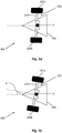
- Figure 2d and figure 2e illustrate schematic plan views of the NLG 102.
- the wheel arrangement in this example includes the right wheel 202a and left wheel 202b, and an axis 216 on which the right wheel 202a and the left wheel 202b are rotatably mounted.
- Figure 2d illustrates the NLG 102 with the wheel arrangement 202 centered i.e. aligned so that the aircraft travels in a straight line (indicated by the horizontal dashed line).
- Figure 2e shows the NLG 102 with the wheel arrangement 202 rotated away from the centre about point X (corresponding to and lying on the landing gear arm 204) by an angle A.
- FIG. 3 is a schematic diagram illustrating a controller 300 and a steering system 301 in accordance with an embodiment.
- the steering system 301 comprises the NLG 102 and various components of a steering system arranged to rotate the wheel arrangement 202 of the NLG 102.
- the controller 300 is an apparatus arranged to control the operation of the steering system in response to signals received from sensors 302a, 302b indicating a position (alignment) of the wheel arrangement 202, as will be described in more detail below.
- the steering system 301 in the present example includes various hydraulic components, including a right actuator 304a, a left actuator 304b, a metering valve 306 including a right port 308a and a left port 308b, a hydraulic pressure supply system 310, a hydraulic return system 312 and a steering controller 314.
- the hydraulic pressure supply system 310 may include a source of hydraulic pressure provided, for example, by a pump powered by an engine of the aircraft 100, manifolds and/or other components configured to route pressurised hydraulic fluid towards other components of the steering system 301.
- the hydraulic return system 312 may include manifolds and/or other components to route hydraulic fluid to a hydraulic fluid reservoir, for example.
- the metering valve 306 is configured to route hydraulic fluid from the hydraulic pressure supply system 310 selectively to the right actuator 304a or the left actuator 304b, under the control of the controller 300 and/or the steering controller 314, thereby causing the wheel arrangement 202 to rotate about the point X, as is described in more detail below.
- the steering controller 314 is typically located in a flight deck of the aircraft 100 and enables, for example, manual control of the steering system 301.
- the steering controller 314 may comprise a wheel, tiller or joystick, for example, with mechanical, electrical or hydraulic connections transmitting the steering controller 314 input movement to a steering control unit.
- the controller 300 is typically a computerised device, and may form part of an avionic system of the aircraft 100, for example.
- the controller is connected via wired or unwired electronic connections to the meter valve 306 and the sensors 302a, 302b.
- FIG 3 illustrates an example in which the metering valve 306 has received input from the controller 300 or the steering controller 314 to rotate the wheel arrangement 202 to the right.
- pressured fluid from the hydraulic pressure supply system 310 is directed into a line leading to the metering valve 306.
- the metering valve 306 routes the pressurised fluid out of the left port 308b of the metering valve 306 to the left actuator 304b.
- Each of the actuators 304a, 304b comprises a cylinder 316a, 316b in which a piston 316 is slidably mounted with one end of each piston connected to a rotable component on the NLG 102, such as the steering collar 212 .
- the fluid pressure from the meter valve 306 directed to the left actuator 304b drives the piston 304b to move so as to push the steering collar 212 (or other component) and thereby compel the wheel arrangement 202 to the right.
- hydraulic fluid is forced out of the right actuator 304a to the metering valve 306, from where it is routed to the hydraulic return system 312. It will be appreciated that by the metering valve 306 routing pressurised hydraulic fluid out of the right port 308a instead of the left port 308b, the wheel arrangement 202 can similarly be turned to the left.
- the wheel arrangement 202 is typically centred prior to the NLG 102 being retracted into the landing gear bay 200, under the control of the controller 300, for example. However, the wheel arrangement 202 may move away from the centre position due to, for example, equipment malfunction or accidental use of the steering controller 314 during a flight.
- the controller 300 is arranged to perform a control process to adjust the position of the wheel arrangement 102 on the basis one or more signals received from one or more of the sensors 302a, 302b.
- the controller 300 may be a computerised device.
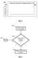
- Figure 4 shows a schematic diagram of an example controller 300.
- the controller includes one or more processors 400 and a non-transitory computer-readable storage medium 402 including instructions 404 in the form of a computer program that, when executed by the one or more processors 400, cause the one or more processors 400 to perform a method according to an embodiment of the present invention.
- the non-transitory computer-readable storage medium may comprise a Read Only Memory (ROM) or Random Access Memory (RAM), for example.
- the sensors 302a, 302b are arranged to determine a position (e.g. alignment or angular position) of the wheel arrangement 202.
- Each of the sensors 302a, 302b may be a steering angle sensor, such as a rotary variable differential transducer, for example.
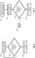
- Figure 5 is a flow diagram illustrating a control process performed by the controller 300 in a first embodiment.
- the controller receives one or more signals from one or more of the sensors 302a, 302b indicating a position of the wheel arrangement 202 when the NLG 102 is in the stowed configuration.
- the controller 300 determines whether a predetermined condition is satisfied in relation to a position of the wheel arrangement 202.
- the predetermined condition may be that the position of the wheel arrangement 202 is greater than a threshold value (e.g. 1.5 degrees or 2 degrees) away from a centre position (i.e. that the magnitude of the angle A shown in figure 2e is greater than a threshold value).
- the controller 300 performs an adjustment process to control the steering system 301 to adjust the position of the wheel arrangement 202 at step 504. This may involve implementing processes as described above in relation to figure 3 , for example.
- the adjustment process may be a centering process to return the wheel arrangement 202 to or near the centre position.
- the controller 300 may monitor the position of the wheel arrangement 202 based on signals received from the sensors 202a, 202b during the adjustment process and end the process once the wheel arrangement 202 is at or near the centre position.
- the controller 300 performs the control process continuously or intermittently during a flight period of the aircraft 100, during which the NLG 102 is in the stowed configuration.
- Figure 6 is a flow diagram illustrating an example. Steps 600, 602 and 604 are the same as steps 500, 502 and 504 respectively. However, in the case that it is determined at step 602 that the predetermined condition is not satisfied, the process returns to step 600. In this way, the position of the wheel arrangement 202 may be continuously monitored, so that the wheel arrangement 202 may be recentred substantially immediately it moves by more than the threshold value.
- the controller 300 may wait, for a predetermined time period for example, after the determination at step 602 that the predetermined condition is not met, before receiving and processing further signals from the sensors 302a, 302b, so that the control process is performed intermittently, for example periodically, while the NLG 102 is in the stowed configuration.
- the control process is performed as part of a process to deploy the NLG 102, as part of an aircraft landing procedure for example.
- Figure 7 is a flow diagram illustrating an example.
- the controller 300 receives a command to deploy the landing gear.
- the command may be received in response to an input from the flight deck, for example.
- the controller 300 then performs steps a control process as described above in relation to figure 5 for example, before deploying the landing gear.
- Steps 700, 702, 704 and 706 in figure 7 are the same as steps 500, 502, 504 and 506, respectively.
- the control process may thus be performed as a one-time process immediately prior to landing. This avoids repeated use of the controller 300 and steering system 301, saving computing and power resources.
- the controller 300 and steering system 301 act as a landing gear control system to inhibit or prevent misalignment (an-off centre alignment) of the wheel arrangement 202 at aircraft landing, without the use of mechanical or other safety valves, thereby reducing the number of components required for the steering system.
- one or more safety valves may be included.
- an electric shut off valve may be provided, on the line between the electric power supply system 310 and the metering valve 306 for example, to isolate the actuators 302a, 302b from the hydraulic power supply system 310.
- the electric shut off valve may be controllable by the controller 300 or by manual input.
- the electric shut off valve may be automatically closed in response to the NLG 102 being retracted into the landing gear bay 200. This may further inhibit misalignment of the wheel arrangement 202.
- the control process may be performed in the case wheel arrangement 202 is misaligned due to, for example, the electric shut off valve being opened due to human error, or a false determination that the aircraft has landed.
- the adjustment process includes opening the valve, thereby powering the steering system.
- embodiments of the invention are to be understood as illustrative examples of the invention.
- a hydraulic steering system 301 was described above, embodiments of the invention may be implemented using an electric or other type of steering system.
- the wheel arrangement 202 includes two wheels 202a, 202b, in other embodiments wheel arrangements including only one wheel or more than two wheels, may be used.
Landscapes
- Engineering & Computer Science (AREA)
- Mechanical Engineering (AREA)
- Aviation & Aerospace Engineering (AREA)
- Steering Control In Accordance With Driving Conditions (AREA)
Abstract
Description
- The present invention relates to aircraft steering systems, and more particularly to apparatus and methods for controlling aircraft steering systems.
- Aircraft often include steering systems to control the direction of movement of the aircraft when the aircraft is moving on the ground ("taxiing"). Typically, such steering systems include wheels forming part of a landing gear which is retracted into a landing gear bay after take-off and deployed from the landing gear bay prior to landing the aircraft. When on the ground, the aircraft is supported by the landing gear and moves by rotation of the landing gear wheels. In a common example, an aircraft includes a nose landing gear located under the aircraft nose and main landing gears located under the aircraft wings. The nose landing gear wheels are typically pivotable about a vertical axis to alter the direction of orientation of the nose landing gear wheels, thereby altering the direction of movement of the aircraft.
- It is desirable that the steering system is correctly orientated (e.g. centered) when the aircraft lands, to correspond with the direction of travel of the aircraft at the point of landing. Deviation from the correct orientation may result in an uncomfortable or unsafe aircraft landing.
- Typically, procedures for retraction of the landing gear include procedures for centering the nose landing gear prior to storing it in the landing gear bay. For example, sensor may detect that the a shock absorber on the landing gear is fully extended, indicating that the landing gear is not bearing the aircraft weight because the aircraft has left the ground, and automatically centre the landing gear wheels in response. However, the landing gear wheels may move away from the centre position due to, for example, equipment malfunction or accidental use of the steering control system during a flight, some aircraft include components to disable the steering system during the flight period, so as to prevent movement of the wheels. For example, some aircraft include a mechanically activated valve, known as a mechanical shut off valve, to isolate hydraulic actuators of the steering system from a source of hydraulic pressure. Such valves may be activated by a link arm or other structure which comes into contact with the valve when the landing gear is retracted. However, such valves add weight to the aircraft and increase costs.
- A first aspect of the invention provides a control apparatus for controlling a steering system of an aircraft landing gear, the aircraft landing gear being configurable in a stowed configuration in which the aircraft landing gear is stowed in a landing gear bay of the aircraft, and a deployed configuration, in which the landing gear is deployed outside of the landing gear bay, the steering system comprising a wheel arrangement including one or more wheels, wherein the control apparatus is arranged to perform a control process comprising: receiving one or more signals from one or more sensors indicating a position of the wheel arrangement when the landing gear is in the stowed configuration; determining whether a predetermined condition is satisfied in relation to the position of the wheel arrangement; and in response to determining that the predetermined condition is satisfied, performing an adjustment process to control the steering system to adjust the position of the wheel arrangement.
- Optionally, the predetermined condition is that the position of the one or more wheels is greater than a threshold value away from a centre position of the wheel arrangement.
- Optionally, the adjustment process is to move the position of the wheel arrangement towards a centre position.
- Optionally, the control apparatus is arranged to perform the control process in response to a command to deploy the landing gear.
- Optionally, the control apparatus is arranged to perform the control process continuously or intermittently during a flight period of the aircraft, during which the aircraft landing gear is in the stowed configuration.
- Optionally, the control process comprises activating the steering system in response to determining that the predetermined condition is satisfied.
- Optionally, the control process comprises maintaining activation of the steering system during substantially the whole of the flight period.
- A second aspect of the control process provides an aircraft landing gear control system comprising a control apparatus according to the first aspect, and the steering system, the steering system being a hydraulic steering system comprising hydraulic actuators to rotate the one or more wheels.
- Optionally, the hydraulic steering system does not include a mechanically activated valve to isolate the hydraulic actuators from a source of hydraulic pressure to the hydraulic actuators.
- Optionally, the aircraft landing gear control system comprises the one or more sensors, wherein the or each sensor comprises a variable differential transducer.
- A third aspect of the invention provides an aircraft comprising the aircraft landing gear according to the second aspect.
- A fourth aspect of the invention provides a method for controlling a steering system of an aircraft landing gear, the aircraft landing gear being configurable in a stowed configuration in which the aircraft landing gear is stowed into a landing gear bay of the aircraft, and a deployed configuration, in which the landing gear is deployed outside of the landing gear bay, the steering system comprising a wheel arrangement including one or more wheels, wherein the method comprises: receiving one or more signals from one or more sensors indicating a position of the wheel arrangement when the landing gear is in the stowed configuration; determining whether a predetermined condition is satisfied in relation to the position of the wheel arrangement; and in response to determining that the predetermined condition is satisfied, performing an adjustment process to control the steering system to adjust the position of the wheel arrangement.
- Optionally, the predetermined condition is that the position of the one or more wheels is greater than a threshold value away from a centre position of the wheel arrangement.
- Optionally, the adjustment process is to move the position of the wheel arrangement towards a centre position.
- Optionally, the method comprises performing the control process in response to a command to deploy the landing gear.
- Optionally, the method comprises performing the control process continuously or intermittently during a flight period of the aircraft, during which the aircraft landing gear is in the stowed configuration.
- Optionally, the method comprises activating the steering system in response to determining that the predetermined condition is satisfied.
- Optionally, the method comprises activating the steering apparatus during substantially the whole of the flight period.
- A fifth aspect of the invention provides a computer program comprising computer-executable instructions to perform a method the fourth aspect.
- A sixth aspect of the invention provides apparatus for maintaining a centre position of a steering system of an aircraft landing gear, the apparatus being configured to: receive one or more signals from one or more sensors indicating whether the steering system is in the centre position during a period when the landing gear is retracted in a landing gear bay of the aircraft; and in the case that the one or more signals indicated that the wheel arrangement is not in the centre position, control the steering system to re-centre the steering system.
- Embodiments of the invention will now be described, by way of example only, with reference to the accompanying drawings, in which:
-
Figure 1 is a schematic diagram showing side and front views of an aircraft of an embodiment of the invention; -
Figure 2a is a schematic diagram of a landing gear bay and landing gear of the aircraft with the landing gear in a stowed configuration; -
Figure 2b is a schematic diagram of the landing gear bay and the landing gear with the landing gear in a deployed configuration; -
Figure 2c is a schematic perspective view of a landing gear of the aircraft; -
Figure 2d is a schematic plan view of the landing gear with a wheel arrangement of the landing gear aligned in a centre position; -
Figure 2e is a schematic plan view of the landing gear with the wheel arrangement in an off-centre position; -
Figure 3 is a schematic diagram of a steering system and controller according to an embodiment of the invention; -
Figure 4 is a block diagram of the controller; -
Figure 5 is a flow diagram showing a control process in accordance with a first embodiment; -
Figure 6 is a flow diagram showing a control process in accordance with a second embodiment; -
Figure 7 is a flow diagram showing a control process in accordance with a third embodiment. -
Figure 1 illustrates front and side elevations of anexemplary aircraft 100, in which embodiments of the present invention may be implemented. Three sets of landing gear are illustrated:nose 102, main left 104 and main right 106. Typically, the wheels of the nose landing gear (NLG) 102 are rotatable about a vertical axis in order to steer (change the direction of movement) of the aircraft when it is traveling on the ground. -
Figures 2a and 2b illustrate simplified schematic side elevations of alanding gear bay 200 and aNLG 102 in which embodiments of the invention may be implemented. The NLG 102 comprises awheel arrangement 202, and alanding gear leg 204 which connects the wheel to apivot point 206 in thelanding gear bay 200.Figure 2a illustrates theNLG 102 in a stowed (retracted) configuration in which the NLG 102 is stowed into thelanding gear bay 200.Figure 2b illustrates the NLG 102 in a deployed (extended) configuration in which the NLG 102 is deployed outside of thelanding gear bay 200. Thelanding gear bay 200 includes anaperture 208 through which the NLG 102 may move between the stowed configuration offigure 2a and the deployed configuration offigure 2b by pivoting about thepivot point 206. Thelanding gear bay 200 may include a door (not shown) which can be opened to allow the NLG 102 to move between the stowed and deployed configurations but which is closed at other times. The movement between the deployed and stowed configurations may be driven by a hydraulic or electric system, for example. - The NLG 102 is typically retracted to the stowed configuration after the
aircraft 100 leaves the ground and maintained in the stowed configuration until a time shortly before theaircraft 100 lands. Maintaining the NLG 102 in the stowed configuration while the aircraft is flying reduces air resistance, providing benefits such as improved fuel efficiency. -
Figure 2c shows a perspective view of the NLG 102. As shown, thelanding gear leg 204 of the NLG 102 comprises amain fitting 209 with an upper end connecting to the aircraft structure, for example to the pivot point 206 (not shown infigure 2c ). The lower end of thelanding gear leg 204 is connected to aright wheel 202a and aleft wheel 202b of thewheel arrangement 202 via an axle or axles (not shown infigure 2c ). Thelanding gear leg 204 includes aslider 210 at its lower end able rotate inside themain fitting 209. Asteering collar 212 is rotatably mounted on the outside of themain fitting 209 at its lower end. Torque links 214 are coupled between thesteering collar 214 and theslider 210 such that theslider 210 rotates inside the main fitting as the steering collar rotates about themain fitting 209. The slider is mounted to the wheel axle or axles and rotation of the slider therefore results in rotation of thewheel arrangement 202 to steer the aircraft. -
Figure 2d and figure 2e illustrate schematic plan views of theNLG 102. As shown, the wheel arrangement in this example includes theright wheel 202a and leftwheel 202b, and anaxis 216 on which theright wheel 202a and theleft wheel 202b are rotatably mounted.Figure 2d illustrates theNLG 102 with thewheel arrangement 202 centered i.e. aligned so that the aircraft travels in a straight line (indicated by the horizontal dashed line).Figure 2e shows theNLG 102 with thewheel arrangement 202 rotated away from the centre about point X (corresponding to and lying on the landing gear arm 204) by an angle A. -
Figure 3 is a schematic diagram illustrating acontroller 300 and asteering system 301 in accordance with an embodiment. Thesteering system 301 comprises theNLG 102 and various components of a steering system arranged to rotate thewheel arrangement 202 of theNLG 102. Thecontroller 300 is an apparatus arranged to control the operation of the steering system in response to signals received fromsensors 302a, 302b indicating a position (alignment) of thewheel arrangement 202, as will be described in more detail below. - The
steering system 301 in the present example includes various hydraulic components, including aright actuator 304a, aleft actuator 304b, ametering valve 306 including aright port 308a and aleft port 308b, a hydraulicpressure supply system 310, ahydraulic return system 312 and asteering controller 314. - The hydraulic
pressure supply system 310 may include a source of hydraulic pressure provided, for example, by a pump powered by an engine of theaircraft 100, manifolds and/or other components configured to route pressurised hydraulic fluid towards other components of thesteering system 301. Thehydraulic return system 312 may include manifolds and/or other components to route hydraulic fluid to a hydraulic fluid reservoir, for example. - The
metering valve 306 is configured to route hydraulic fluid from the hydraulicpressure supply system 310 selectively to theright actuator 304a or theleft actuator 304b, under the control of thecontroller 300 and/or thesteering controller 314, thereby causing thewheel arrangement 202 to rotate about the point X, as is described in more detail below. - The
steering controller 314 is typically located in a flight deck of theaircraft 100 and enables, for example, manual control of thesteering system 301. Thesteering controller 314 may comprise a wheel, tiller or joystick, for example, with mechanical, electrical or hydraulic connections transmitting thesteering controller 314 input movement to a steering control unit. - The
controller 300 is typically a computerised device, and may form part of an avionic system of theaircraft 100, for example. The controller is connected via wired or unwired electronic connections to themeter valve 306 and thesensors 302a, 302b. -
Figure 3 illustrates an example in which themetering valve 306 has received input from thecontroller 300 or thesteering controller 314 to rotate thewheel arrangement 202 to the right. As shown by the arrows inFigure 3 , pressured fluid from the hydraulicpressure supply system 310 is directed into a line leading to themetering valve 306. Themetering valve 306 routes the pressurised fluid out of theleft port 308b of themetering valve 306 to theleft actuator 304b. Each of the actuators 304a, 304b comprises acylinder NLG 102, such as thesteering collar 212 . The fluid pressure from themeter valve 306 directed to theleft actuator 304b drives thepiston 304b to move so as to push the steering collar 212 (or other component) and thereby compel thewheel arrangement 202 to the right. As thewheel arrangement 202 turns, hydraulic fluid is forced out of theright actuator 304a to themetering valve 306, from where it is routed to thehydraulic return system 312. It will be appreciated that by themetering valve 306 routing pressurised hydraulic fluid out of theright port 308a instead of theleft port 308b, thewheel arrangement 202 can similarly be turned to the left. - The
wheel arrangement 202 is typically centred prior to theNLG 102 being retracted into thelanding gear bay 200, under the control of thecontroller 300, for example. However, thewheel arrangement 202 may move away from the centre position due to, for example, equipment malfunction or accidental use of thesteering controller 314 during a flight. In embodiments of the present invention, thecontroller 300 is arranged to perform a control process to adjust the position of thewheel arrangement 102 on the basis one or more signals received from one or more of thesensors 302a, 302b. - As mentioned above, the
controller 300 may be a computerised device.Figure 4 shows a schematic diagram of anexample controller 300. The controller includes one ormore processors 400 and a non-transitory computer-readable storage medium 402 includinginstructions 404 in the form of a computer program that, when executed by the one ormore processors 400, cause the one ormore processors 400 to perform a method according to an embodiment of the present invention. The non-transitory computer-readable storage medium may comprise a Read Only Memory (ROM) or Random Access Memory (RAM), for example. - The
sensors 302a, 302b are arranged to determine a position (e.g. alignment or angular position) of thewheel arrangement 202. Each of thesensors 302a, 302b may be a steering angle sensor, such as a rotary variable differential transducer, for example. -
Figure 5 is a flow diagram illustrating a control process performed by thecontroller 300 in a first embodiment. Atstep 500, the controller receives one or more signals from one or more of thesensors 302a, 302b indicating a position of thewheel arrangement 202 when theNLG 102 is in the stowed configuration. - At
step 502, thecontroller 300 determines whether a predetermined condition is satisfied in relation to a position of thewheel arrangement 202. For example, the predetermined condition may be that the position of thewheel arrangement 202 is greater than a threshold value (e.g. 1.5 degrees or 2 degrees) away from a centre position (i.e. that the magnitude of the angle A shown infigure 2e is greater than a threshold value). - If the predetermined condition is satisfied, the
controller 300 performs an adjustment process to control thesteering system 301 to adjust the position of thewheel arrangement 202 atstep 504. This may involve implementing processes as described above in relation tofigure 3 , for example. The adjustment process may be a centering process to return thewheel arrangement 202 to or near the centre position. Thecontroller 300 may monitor the position of thewheel arrangement 202 based on signals received from thesensors wheel arrangement 202 is at or near the centre position. - If the predetermined condition is not satisfied, the process ends at
step 506. - In some embodiments, the
controller 300 performs the control process continuously or intermittently during a flight period of theaircraft 100, during which theNLG 102 is in the stowed configuration.Figure 6 is a flow diagram illustrating an example.Steps steps step 602 that the predetermined condition is not satisfied, the process returns to step 600. In this way, the position of thewheel arrangement 202 may be continuously monitored, so that thewheel arrangement 202 may be recentred substantially immediately it moves by more than the threshold value. In some embodiments, thecontroller 300 may wait, for a predetermined time period for example, after the determination atstep 602 that the predetermined condition is not met, before receiving and processing further signals from thesensors 302a, 302b, so that the control process is performed intermittently, for example periodically, while theNLG 102 is in the stowed configuration. - In some embodiments, the control process is performed as part of a process to deploy the
NLG 102, as part of an aircraft landing procedure for example.Figure 7 is a flow diagram illustrating an example. Atstep 70, thecontroller 300 receives a command to deploy the landing gear. The command may be received in response to an input from the flight deck, for example. In response to receipt of the command, thecontroller 300 then performs steps a control process as described above in relation tofigure 5 for example, before deploying the landing gear.Steps figure 7 are the same assteps controller 300 andsteering system 301, saving computing and power resources. - According to the above embodiments, the
controller 300 andsteering system 301 act as a landing gear control system to inhibit or prevent misalignment (an-off centre alignment) of thewheel arrangement 202 at aircraft landing, without the use of mechanical or other safety valves, thereby reducing the number of components required for the steering system. However, in some embodiments one or more safety valves may be included. For example, an electric shut off valve may be provided, on the line between the electricpower supply system 310 and themetering valve 306 for example, to isolate the actuators 302a, 302b from the hydraulicpower supply system 310. The electric shut off valve may be controllable by thecontroller 300 or by manual input. In one example, the electric shut off valve may be automatically closed in response to theNLG 102 being retracted into thelanding gear bay 200. This may further inhibit misalignment of thewheel arrangement 202. In this case, the control process may be performed in thecase wheel arrangement 202 is misaligned due to, for example, the electric shut off valve being opened due to human error, or a false determination that the aircraft has landed. In the event that the electric shut off valve is closed when, during the control process, the predetermined condition is determined to be met, the adjustment process includes opening the valve, thereby powering the steering system. - The above embodiments are to be understood as illustrative examples of the invention. For example, while a
hydraulic steering system 301 was described above, embodiments of the invention may be implemented using an electric or other type of steering system. Further, while in above embodiments thewheel arrangement 202 includes twowheels - It is to noted that the term "or" as used herein is to be interpreted to mean "and/or", unless expressly stated otherwise.
- It is to be understood that any feature described in relation to any one embodiment may be used alone, or in combination with other features described, and may also be used in combination with one or more features of any other of the embodiments, or any combination of any other of the embodiments. Furthermore, equivalents and modifications not described above may also be employed without departing from the scope of the invention, which is defined in the accompanying claims.
Claims (15)
- A control apparatus for controlling a steering system of an aircraft landing gear, the aircraft landing gear being configurable in a stowed configuration in which the aircraft landing gear is stowed in a landing gear bay of the aircraft, and a deployed configuration, in which the landing gear is deployed outside of the landing gear bay, the steering system comprising a wheel arrangement including one or more wheels, wherein the control apparatus is arranged to perform a control process comprising:receiving one or more signals from one or more sensors indicating a position of the wheel arrangement when the landing gear is in the stowed configuration;determining whether a predetermined condition is satisfied in relation to the position of the wheel arrangement; andin response to determining that the predetermined condition is satisfied, performing an adjustment process to control the steering system to adjust the position of the wheel arrangement.
- A control apparatus according to claim 1, wherein the predetermined condition is that the position of the one or more wheels is greater than a threshold value away from a centre position of the wheel arrangement.
- A control apparatus according to either of claim 1 and claim 2, wherein the adjustment process is to move the position of the wheel arrangement towards a centre position.
- A control apparatus according to any preceding claim, arranged to perform the control process in response to a command to deploy the landing gear.
- A control apparatus according to any of claim 1 to claim 3, arranged to perform the control process continuously or intermittently during a flight period of the aircraft, during which the aircraft landing gear is in the stowed configuration.
- A control apparatus according to claim 5, wherein the control process comprises activating the steering system in response to determining that the predetermined condition is satisfied.
- A control apparatus according to claim 5, wherein the control process comprises maintaining activation of the steering system during substantially the whole of the flight period.
- An aircraft landing gear control system comprising a control apparatus according to any preceding claim, and the steering system, the steering system being a hydraulic steering system comprising hydraulic actuators to rotate the one or more wheels.
- An aircraft landing gear control system according to claim 8, wherein the hydraulic steering system does not include a mechanically activated valve to isolate the hydraulic actuators from a source of hydraulic pressure to the hydraulic actuators.
- An aircraft landing gear control system according to either of claim 8 and claim 9, comprising the one or more sensors, wherein the or each sensor comprises a variable differential transducer.
- An aircraft comprising an aircraft landing gear control system according to any of claim 8 to claim 10.
- A method for controlling a steering system of an aircraft landing gear, the aircraft landing gear being configurable in a stowed configuration in which the aircraft landing gear is stowed into a landing gear bay of the aircraft, and a deployed configuration, in which the landing gear is deployed outside of the landing gear bay, the steering system comprising a wheel arrangement including one or more wheels, wherein the method comprises:receiving one or more signals from one or more sensors indicating a position of the wheel arrangement when the landing gear is in the stowed configuration;determining whether a predetermined condition is satisfied in relation to the position of the wheel arrangement; andin response to determining that the predetermined condition is satisfied, performing an adjustment process to control the steering system to adjust the position of the wheel arrangement.
- A method according to claim 12, wherein the predetermined condition is that the position of the one or more wheels is greater than a threshold value away from a centre position of the wheel arrangement.
- A computer program comprising computer-executable instructions to perform the method of claim 13.
- Apparatus for maintaining a centre position of a steering system of an aircraft landing gear, the apparatus being configured to:receive one or more signals from one or more sensors indicating whether the steering system is in the centre position during a period when the landing gear is retracted in a landing gear bay of the aircraft; andin the case that the one or more signals indicated that the wheel arrangement is not in the centre position, control the steering system to re-centre the steering system.
Applications Claiming Priority (1)
| Application Number | Priority Date | Filing Date | Title |
|---|---|---|---|
| GB1710217.9A GB2563851B (en) | 2017-06-27 | 2017-06-27 | Aircraft steering |
Publications (2)
| Publication Number | Publication Date |
|---|---|
| EP3421356A1 true EP3421356A1 (en) | 2019-01-02 |
| EP3421356B1 EP3421356B1 (en) | 2021-11-24 |
Family
ID=59523529
Family Applications (1)
| Application Number | Title | Priority Date | Filing Date |
|---|---|---|---|
| EP18180031.9A Active EP3421356B1 (en) | 2017-06-27 | 2018-06-27 | Aircraft steering |
Country Status (3)
| Country | Link |
|---|---|
| US (1) | US10569864B2 (en) |
| EP (1) | EP3421356B1 (en) |
| GB (1) | GB2563851B (en) |
Cited By (2)
| Publication number | Priority date | Publication date | Assignee | Title |
|---|---|---|---|---|
| CN114313230A (en) * | 2022-01-24 | 2022-04-12 | 中国商用飞机有限责任公司 | Landing gear retraction system and method, computer readable medium |
| EP4410670A1 (en) * | 2023-01-31 | 2024-08-07 | Airbus Operations Limited | Determining aircraft steering angle |
Families Citing this family (4)
| Publication number | Priority date | Publication date | Assignee | Title |
|---|---|---|---|---|
| GB2563851B (en) * | 2017-06-27 | 2020-04-01 | Airbus Operations Ltd | Aircraft steering |
| EP3486177B1 (en) * | 2017-11-21 | 2022-08-24 | Safran Landing Systems UK Ltd | Aircraft landing gear assembly actuation system |
| US11066153B2 (en) | 2019-09-20 | 2021-07-20 | Goodrich Corporation | Electric nose landing gear architecture |
| GB2626921A (en) * | 2023-01-31 | 2024-08-14 | Airbus Operations Ltd | Determining a position of a component of an aircraft landing gear assembly |
Citations (3)
| Publication number | Priority date | Publication date | Assignee | Title |
|---|---|---|---|---|
| GB2480623A (en) * | 2010-05-25 | 2011-11-30 | Messier Dowty Ltd | Steerable landing gear with locking mechanism |
| US20130015290A1 (en) * | 2011-07-12 | 2013-01-17 | Messier-Bugatti-Dowty | Method of managing the steering of aircraft wheels, in particular in the event of a tire bursting or deflating |
| US20130233966A1 (en) * | 2011-11-10 | 2013-09-12 | Messier-Bugatti-Dowty | Method of resetting the orientation of an aircraft undercarriage having a steerable bottom portion |
Family Cites Families (22)
| Publication number | Priority date | Publication date | Assignee | Title |
|---|---|---|---|---|
| GB650878A (en) * | 1947-10-20 | 1951-03-07 | Electro Hydraulics Ltd | Improvements in or relating to fluid pressure actuated control steering systems |
| JP3147539B2 (en) * | 1992-10-05 | 2001-03-19 | 本田技研工業株式会社 | Aircraft landing gear |
| US6671588B2 (en) * | 2001-12-27 | 2003-12-30 | Toyota Jidosha Kabushiki Kaisha | System and method for controlling traveling direction of aircraft |
| US6704634B1 (en) * | 2002-11-06 | 2004-03-09 | The Boeing Company | Gear retract braking system and method |
| US6722610B1 (en) * | 2002-11-25 | 2004-04-20 | The Boeing Company | Method, system, and computer program product for controlling maneuverable wheels on a vehicle |
| FR2875900B1 (en) * | 2004-09-28 | 2006-12-08 | Airbus France Sas | METHOD AND DEVICE FOR MEASURING THE ORIENTATION OF THE LANDING TRAIN BEFORE AN AIRCRAFT |
| US7281684B2 (en) * | 2005-02-23 | 2007-10-16 | The Boeing Company | Systems and methods for braking aircraft, including braking intermediate main gears and differential braking |
| US7364121B2 (en) * | 2005-03-14 | 2008-04-29 | The Boeing Company | Methods and systems for automatically controlling aircraft takeoff rolls |
| FR2887516B1 (en) * | 2005-06-27 | 2008-10-03 | Messier Bugatti Sa | DISTRIBUTED ARCHITECTURE OF AIRCRAFT AIRCRAFT MANAGEMENT SYSTEM |
| US7975960B2 (en) * | 2005-08-29 | 2011-07-12 | Borealis Technical Limited | Nosewheel control apparatus |
| US9085285B2 (en) * | 2006-01-19 | 2015-07-21 | Hydro-Aire, Inc. | System and method for aircraft brake metering to alleviate structural loading |
| US20090210105A1 (en) * | 2006-05-15 | 2009-08-20 | Lusby Brock D | Air-ground detection system and method |
| GB0702332D0 (en) * | 2007-02-07 | 2007-03-21 | Airbus Uk Ltd | A method, apparatus or software for controlling the heading of an aircraft on the ground |
| US8123161B1 (en) * | 2008-06-03 | 2012-02-28 | Hamilton Sundstrand Corporation | Aircraft landing gear unlock actuator |
| FR2976911B1 (en) * | 2011-06-27 | 2013-07-05 | Messier Bugatti Dowty | METHOD FOR CONTROLLING THE ORIENTATION OF AN ORIENTABLE PART OF AN AIRCRAFT INTERFERENCE. |
| US20130197739A1 (en) * | 2012-01-31 | 2013-08-01 | Gulfstream Aerospace Corporation | Methods and systems for aircraft health and trend monitoring |
| FR2986503B1 (en) * | 2012-02-06 | 2014-10-10 | Messier Bugatti Dowty | METHOD FOR MANAGING ORIENTATION CONTROL OF AN ORIENTABLE PART OF AN AIRCRAFT INTERFERENCE. |
| EP2902315A1 (en) * | 2014-02-04 | 2015-08-05 | General Atomics Aeronautical Systems, Inc. | Landing gear deployment systems and methods |
| US9567106B2 (en) * | 2014-11-21 | 2017-02-14 | Taleris Global Llp | System and method for identifying faults in an aircraft |
| JP6549849B2 (en) * | 2015-01-26 | 2019-07-24 | 三菱航空機株式会社 | Heat removal structure of aircraft main landing gear bay |
| EP3178738A1 (en) * | 2015-12-07 | 2017-06-14 | Safran Landing Systems UK Limited | Fully electric speed-proportional nose wheel steering system for an aircraft |
| GB2563851B (en) * | 2017-06-27 | 2020-04-01 | Airbus Operations Ltd | Aircraft steering |
-
2017
- 2017-06-27 GB GB1710217.9A patent/GB2563851B/en not_active Expired - Fee Related
-
2018
- 2018-06-25 US US16/017,018 patent/US10569864B2/en active Active
- 2018-06-27 EP EP18180031.9A patent/EP3421356B1/en active Active
Patent Citations (3)
| Publication number | Priority date | Publication date | Assignee | Title |
|---|---|---|---|---|
| GB2480623A (en) * | 2010-05-25 | 2011-11-30 | Messier Dowty Ltd | Steerable landing gear with locking mechanism |
| US20130015290A1 (en) * | 2011-07-12 | 2013-01-17 | Messier-Bugatti-Dowty | Method of managing the steering of aircraft wheels, in particular in the event of a tire bursting or deflating |
| US20130233966A1 (en) * | 2011-11-10 | 2013-09-12 | Messier-Bugatti-Dowty | Method of resetting the orientation of an aircraft undercarriage having a steerable bottom portion |
Cited By (3)
| Publication number | Priority date | Publication date | Assignee | Title |
|---|---|---|---|---|
| CN114313230A (en) * | 2022-01-24 | 2022-04-12 | 中国商用飞机有限责任公司 | Landing gear retraction system and method, computer readable medium |
| EP4410670A1 (en) * | 2023-01-31 | 2024-08-07 | Airbus Operations Limited | Determining aircraft steering angle |
| US12545430B2 (en) | 2023-01-31 | 2026-02-10 | Airbus Operations Limited | Determining aircraft steering angle |
Also Published As
| Publication number | Publication date |
|---|---|
| GB2563851B (en) | 2020-04-01 |
| US20190002091A1 (en) | 2019-01-03 |
| GB2563851A (en) | 2019-01-02 |
| EP3421356B1 (en) | 2021-11-24 |
| GB201710217D0 (en) | 2017-08-09 |
| US10569864B2 (en) | 2020-02-25 |
Similar Documents
| Publication | Publication Date | Title |
|---|---|---|
| EP3421356B1 (en) | Aircraft steering | |
| US8894005B2 (en) | Landing gear assembly of aircraft | |
| US9102402B2 (en) | Landing gear, an aircraft, and a method | |
| US10196131B2 (en) | Hydraulic system and method for an aircraft flight control system | |
| EP3254956B1 (en) | Foldable wing with an actuator arrangement | |
| US20120032030A1 (en) | High lift system for an airplane, airplane system and propeller airplane having a high lift system | |
| US20060284019A1 (en) | Controllable refueling drogues and associated systems and methods | |
| EP2924529A1 (en) | System for a vehicle with redundant computers | |
| US20170158316A1 (en) | Fully electric speed-proportional nose wheel steering system for an aircraft | |
| CN101301929A (en) | Redundant flight control surface execution system and method for load optimization | |
| CN103105857B (en) | For resetting the method for the orientation with the aircraft landing gear that can turn to bottom | |
| BRPI0800191B1 (en) | method for managing a steering control of an aircraft landing gear | |
| EP3702270B1 (en) | Landing gear retraction | |
| EP3652071A1 (en) | Refueling device | |
| US20200140063A1 (en) | Horizontal stabilizer trim actuator systems and methods | |
| JP2012218447A5 (en) | ||
| US20110046819A1 (en) | Method and system for deactivating a steering system of an aircraft's front landing gear | |
| CN101025128A (en) | Axial symmetric vector spray-pipe A9 action emergency resetting hydraulic system | |
| US20250138559A1 (en) | Command monitor backup control architecture | |
| EP3339116A1 (en) | Arbitration of multiple systems using shared components | |
| CN113009926B (en) | Unmanned aerial vehicle multisensor's integration test measurement system | |
| CN116588323A (en) | High-lift system, aircraft and control method for high-lift system | |
| RU2539620C1 (en) | Aircraft landing control by heading | |
| US2859927A (en) | Aileron control system | |
| US20250313335A1 (en) | Nose-wheel steering split control architecture systems and methods |
Legal Events
| Date | Code | Title | Description |
|---|---|---|---|
| PUAI | Public reference made under article 153(3) epc to a published international application that has entered the european phase |
Free format text: ORIGINAL CODE: 0009012 |
|
| STAA | Information on the status of an ep patent application or granted ep patent |
Free format text: STATUS: THE APPLICATION HAS BEEN PUBLISHED |
|
| AK | Designated contracting states |
Kind code of ref document: A1 Designated state(s): AL AT BE BG CH CY CZ DE DK EE ES FI FR GB GR HR HU IE IS IT LI LT LU LV MC MK MT NL NO PL PT RO RS SE SI SK SM TR |
|
| AX | Request for extension of the european patent |
Extension state: BA ME |
|
| STAA | Information on the status of an ep patent application or granted ep patent |
Free format text: STATUS: REQUEST FOR EXAMINATION WAS MADE |
|
| 17P | Request for examination filed |
Effective date: 20190702 |
|
| RBV | Designated contracting states (corrected) |
Designated state(s): AL AT BE BG CH CY CZ DE DK EE ES FI FR GB GR HR HU IE IS IT LI LT LU LV MC MK MT NL NO PL PT RO RS SE SI SK SM TR |
|
| GRAP | Despatch of communication of intention to grant a patent |
Free format text: ORIGINAL CODE: EPIDOSNIGR1 |
|
| STAA | Information on the status of an ep patent application or granted ep patent |
Free format text: STATUS: GRANT OF PATENT IS INTENDED |
|
| INTG | Intention to grant announced |
Effective date: 20210622 |
|
| GRAA | (expected) grant |
Free format text: ORIGINAL CODE: 0009210 |
|
| STAA | Information on the status of an ep patent application or granted ep patent |
Free format text: STATUS: THE PATENT HAS BEEN GRANTED |
|
| GRAS | Grant fee paid |
Free format text: ORIGINAL CODE: EPIDOSNIGR3 |
|
| AK | Designated contracting states |
Kind code of ref document: B1 Designated state(s): AL AT BE BG CH CY CZ DE DK EE ES FI FR GB GR HR HU IE IS IT LI LT LU LV MC MK MT NL NO PL PT RO RS SE SI SK SM TR |
|
| REG | Reference to a national code |
Ref country code: GB Ref legal event code: FG4D |
|
| REG | Reference to a national code |
Ref country code: DE Ref legal event code: R096 Ref document number: 602018027042 Country of ref document: DE |
|
| REG | Reference to a national code |
Ref country code: AT Ref legal event code: REF Ref document number: 1449682 Country of ref document: AT Kind code of ref document: T Effective date: 20211215 |
|
| REG | Reference to a national code |
Ref country code: IE Ref legal event code: FG4D |
|
| REG | Reference to a national code |
Ref country code: LT Ref legal event code: MG9D |
|
| REG | Reference to a national code |
Ref country code: NL Ref legal event code: MP Effective date: 20211124 |
|
| REG | Reference to a national code |
Ref country code: AT Ref legal event code: MK05 Ref document number: 1449682 Country of ref document: AT Kind code of ref document: T Effective date: 20211124 |
|
| PG25 | Lapsed in a contracting state [announced via postgrant information from national office to epo] |
Ref country code: RS Free format text: LAPSE BECAUSE OF FAILURE TO SUBMIT A TRANSLATION OF THE DESCRIPTION OR TO PAY THE FEE WITHIN THE PRESCRIBED TIME-LIMIT Effective date: 20211124 Ref country code: LT Free format text: LAPSE BECAUSE OF FAILURE TO SUBMIT A TRANSLATION OF THE DESCRIPTION OR TO PAY THE FEE WITHIN THE PRESCRIBED TIME-LIMIT Effective date: 20211124 Ref country code: FI Free format text: LAPSE BECAUSE OF FAILURE TO SUBMIT A TRANSLATION OF THE DESCRIPTION OR TO PAY THE FEE WITHIN THE PRESCRIBED TIME-LIMIT Effective date: 20211124 Ref country code: BG Free format text: LAPSE BECAUSE OF FAILURE TO SUBMIT A TRANSLATION OF THE DESCRIPTION OR TO PAY THE FEE WITHIN THE PRESCRIBED TIME-LIMIT Effective date: 20220224 Ref country code: AT Free format text: LAPSE BECAUSE OF FAILURE TO SUBMIT A TRANSLATION OF THE DESCRIPTION OR TO PAY THE FEE WITHIN THE PRESCRIBED TIME-LIMIT Effective date: 20211124 |
|
| PG25 | Lapsed in a contracting state [announced via postgrant information from national office to epo] |
Ref country code: IS Free format text: LAPSE BECAUSE OF FAILURE TO SUBMIT A TRANSLATION OF THE DESCRIPTION OR TO PAY THE FEE WITHIN THE PRESCRIBED TIME-LIMIT Effective date: 20220324 Ref country code: SE Free format text: LAPSE BECAUSE OF FAILURE TO SUBMIT A TRANSLATION OF THE DESCRIPTION OR TO PAY THE FEE WITHIN THE PRESCRIBED TIME-LIMIT Effective date: 20211124 Ref country code: PT Free format text: LAPSE BECAUSE OF FAILURE TO SUBMIT A TRANSLATION OF THE DESCRIPTION OR TO PAY THE FEE WITHIN THE PRESCRIBED TIME-LIMIT Effective date: 20220324 Ref country code: PL Free format text: LAPSE BECAUSE OF FAILURE TO SUBMIT A TRANSLATION OF THE DESCRIPTION OR TO PAY THE FEE WITHIN THE PRESCRIBED TIME-LIMIT Effective date: 20211124 Ref country code: NO Free format text: LAPSE BECAUSE OF FAILURE TO SUBMIT A TRANSLATION OF THE DESCRIPTION OR TO PAY THE FEE WITHIN THE PRESCRIBED TIME-LIMIT Effective date: 20220224 Ref country code: NL Free format text: LAPSE BECAUSE OF FAILURE TO SUBMIT A TRANSLATION OF THE DESCRIPTION OR TO PAY THE FEE WITHIN THE PRESCRIBED TIME-LIMIT Effective date: 20211124 Ref country code: LV Free format text: LAPSE BECAUSE OF FAILURE TO SUBMIT A TRANSLATION OF THE DESCRIPTION OR TO PAY THE FEE WITHIN THE PRESCRIBED TIME-LIMIT Effective date: 20211124 Ref country code: HR Free format text: LAPSE BECAUSE OF FAILURE TO SUBMIT A TRANSLATION OF THE DESCRIPTION OR TO PAY THE FEE WITHIN THE PRESCRIBED TIME-LIMIT Effective date: 20211124 Ref country code: GR Free format text: LAPSE BECAUSE OF FAILURE TO SUBMIT A TRANSLATION OF THE DESCRIPTION OR TO PAY THE FEE WITHIN THE PRESCRIBED TIME-LIMIT Effective date: 20220225 Ref country code: ES Free format text: LAPSE BECAUSE OF FAILURE TO SUBMIT A TRANSLATION OF THE DESCRIPTION OR TO PAY THE FEE WITHIN THE PRESCRIBED TIME-LIMIT Effective date: 20211124 |
|
| PG25 | Lapsed in a contracting state [announced via postgrant information from national office to epo] |
Ref country code: SM Free format text: LAPSE BECAUSE OF FAILURE TO SUBMIT A TRANSLATION OF THE DESCRIPTION OR TO PAY THE FEE WITHIN THE PRESCRIBED TIME-LIMIT Effective date: 20211124 Ref country code: SK Free format text: LAPSE BECAUSE OF FAILURE TO SUBMIT A TRANSLATION OF THE DESCRIPTION OR TO PAY THE FEE WITHIN THE PRESCRIBED TIME-LIMIT Effective date: 20211124 Ref country code: RO Free format text: LAPSE BECAUSE OF FAILURE TO SUBMIT A TRANSLATION OF THE DESCRIPTION OR TO PAY THE FEE WITHIN THE PRESCRIBED TIME-LIMIT Effective date: 20211124 Ref country code: EE Free format text: LAPSE BECAUSE OF FAILURE TO SUBMIT A TRANSLATION OF THE DESCRIPTION OR TO PAY THE FEE WITHIN THE PRESCRIBED TIME-LIMIT Effective date: 20211124 Ref country code: DK Free format text: LAPSE BECAUSE OF FAILURE TO SUBMIT A TRANSLATION OF THE DESCRIPTION OR TO PAY THE FEE WITHIN THE PRESCRIBED TIME-LIMIT Effective date: 20211124 Ref country code: CZ Free format text: LAPSE BECAUSE OF FAILURE TO SUBMIT A TRANSLATION OF THE DESCRIPTION OR TO PAY THE FEE WITHIN THE PRESCRIBED TIME-LIMIT Effective date: 20211124 |
|
| REG | Reference to a national code |
Ref country code: DE Ref legal event code: R097 Ref document number: 602018027042 Country of ref document: DE |
|
| PLBE | No opposition filed within time limit |
Free format text: ORIGINAL CODE: 0009261 |
|
| STAA | Information on the status of an ep patent application or granted ep patent |
Free format text: STATUS: NO OPPOSITION FILED WITHIN TIME LIMIT |
|
| PG25 | Lapsed in a contracting state [announced via postgrant information from national office to epo] |
Ref country code: AL Free format text: LAPSE BECAUSE OF FAILURE TO SUBMIT A TRANSLATION OF THE DESCRIPTION OR TO PAY THE FEE WITHIN THE PRESCRIBED TIME-LIMIT Effective date: 20211124 |
|
| 26N | No opposition filed |
Effective date: 20220825 |
|
| PG25 | Lapsed in a contracting state [announced via postgrant information from national office to epo] |
Ref country code: SI Free format text: LAPSE BECAUSE OF FAILURE TO SUBMIT A TRANSLATION OF THE DESCRIPTION OR TO PAY THE FEE WITHIN THE PRESCRIBED TIME-LIMIT Effective date: 20211124 |
|
| PG25 | Lapsed in a contracting state [announced via postgrant information from national office to epo] |
Ref country code: MC Free format text: LAPSE BECAUSE OF FAILURE TO SUBMIT A TRANSLATION OF THE DESCRIPTION OR TO PAY THE FEE WITHIN THE PRESCRIBED TIME-LIMIT Effective date: 20211124 |
|
| REG | Reference to a national code |
Ref country code: CH Ref legal event code: PL |
|
| REG | Reference to a national code |
Ref country code: BE Ref legal event code: MM Effective date: 20220630 |
|
| PG25 | Lapsed in a contracting state [announced via postgrant information from national office to epo] |
Ref country code: LU Free format text: LAPSE BECAUSE OF NON-PAYMENT OF DUE FEES Effective date: 20220627 Ref country code: LI Free format text: LAPSE BECAUSE OF NON-PAYMENT OF DUE FEES Effective date: 20220630 Ref country code: IE Free format text: LAPSE BECAUSE OF NON-PAYMENT OF DUE FEES Effective date: 20220627 Ref country code: CH Free format text: LAPSE BECAUSE OF NON-PAYMENT OF DUE FEES Effective date: 20220630 |
|
| PG25 | Lapsed in a contracting state [announced via postgrant information from national office to epo] |
Ref country code: IT Free format text: LAPSE BECAUSE OF FAILURE TO SUBMIT A TRANSLATION OF THE DESCRIPTION OR TO PAY THE FEE WITHIN THE PRESCRIBED TIME-LIMIT Effective date: 20211124 Ref country code: BE Free format text: LAPSE BECAUSE OF NON-PAYMENT OF DUE FEES Effective date: 20220630 |
|
| PG25 | Lapsed in a contracting state [announced via postgrant information from national office to epo] |
Ref country code: HU Free format text: LAPSE BECAUSE OF FAILURE TO SUBMIT A TRANSLATION OF THE DESCRIPTION OR TO PAY THE FEE WITHIN THE PRESCRIBED TIME-LIMIT; INVALID AB INITIO Effective date: 20180627 |
|
| PG25 | Lapsed in a contracting state [announced via postgrant information from national office to epo] |
Ref country code: MK Free format text: LAPSE BECAUSE OF FAILURE TO SUBMIT A TRANSLATION OF THE DESCRIPTION OR TO PAY THE FEE WITHIN THE PRESCRIBED TIME-LIMIT Effective date: 20211124 Ref country code: CY Free format text: LAPSE BECAUSE OF FAILURE TO SUBMIT A TRANSLATION OF THE DESCRIPTION OR TO PAY THE FEE WITHIN THE PRESCRIBED TIME-LIMIT Effective date: 20211124 |
|
| PG25 | Lapsed in a contracting state [announced via postgrant information from national office to epo] |
Ref country code: MT Free format text: LAPSE BECAUSE OF FAILURE TO SUBMIT A TRANSLATION OF THE DESCRIPTION OR TO PAY THE FEE WITHIN THE PRESCRIBED TIME-LIMIT Effective date: 20211124 |
|
| PGFP | Annual fee paid to national office [announced via postgrant information from national office to epo] |
Ref country code: DE Payment date: 20250618 Year of fee payment: 8 |
|
| PGFP | Annual fee paid to national office [announced via postgrant information from national office to epo] |
Ref country code: GB Payment date: 20250618 Year of fee payment: 8 |
|
| PGFP | Annual fee paid to national office [announced via postgrant information from national office to epo] |
Ref country code: FR Payment date: 20250625 Year of fee payment: 8 |
|
| PG25 | Lapsed in a contracting state [announced via postgrant information from national office to epo] |
Ref country code: TR Free format text: LAPSE BECAUSE OF FAILURE TO SUBMIT A TRANSLATION OF THE DESCRIPTION OR TO PAY THE FEE WITHIN THE PRESCRIBED TIME-LIMIT Effective date: 20211124 |