EP3421328A1 - Parking assistance system - Google Patents
Parking assistance system Download PDFInfo
- Publication number
- EP3421328A1 EP3421328A1 EP18174820.3A EP18174820A EP3421328A1 EP 3421328 A1 EP3421328 A1 EP 3421328A1 EP 18174820 A EP18174820 A EP 18174820A EP 3421328 A1 EP3421328 A1 EP 3421328A1
- Authority
- EP
- European Patent Office
- Prior art keywords
- parking
- vehicle
- controller
- parking space
- diagonal
- Prior art date
- Legal status (The legal status is an assumption and is not a legal conclusion. Google has not performed a legal analysis and makes no representation as to the accuracy of the status listed.)
- Granted
Links
Images


Classifications
-
- B—PERFORMING OPERATIONS; TRANSPORTING
- B62—LAND VEHICLES FOR TRAVELLING OTHERWISE THAN ON RAILS
- B62D—MOTOR VEHICLES; TRAILERS
- B62D15/00—Steering not otherwise provided for
- B62D15/02—Steering position indicators ; Steering position determination; Steering aids
- B62D15/027—Parking aids, e.g. instruction means
- B62D15/0275—Parking aids, e.g. instruction means by overlaying a vehicle path based on present steering angle over an image without processing that image
-
- B—PERFORMING OPERATIONS; TRANSPORTING
- B62—LAND VEHICLES FOR TRAVELLING OTHERWISE THAN ON RAILS
- B62D—MOTOR VEHICLES; TRAILERS
- B62D15/00—Steering not otherwise provided for
- B62D15/02—Steering position indicators ; Steering position determination; Steering aids
- B62D15/027—Parking aids, e.g. instruction means
- B62D15/028—Guided parking by providing commands to the driver, e.g. acoustically or optically
-
- B—PERFORMING OPERATIONS; TRANSPORTING
- B60—VEHICLES IN GENERAL
- B60W—CONJOINT CONTROL OF VEHICLE SUB-UNITS OF DIFFERENT TYPE OR DIFFERENT FUNCTION; CONTROL SYSTEMS SPECIALLY ADAPTED FOR HYBRID VEHICLES; ROAD VEHICLE DRIVE CONTROL SYSTEMS FOR PURPOSES NOT RELATED TO THE CONTROL OF A PARTICULAR SUB-UNIT
- B60W30/00—Purposes of road vehicle drive control systems not related to the control of a particular sub-unit, e.g. of systems using conjoint control of vehicle sub-units
- B60W30/06—Automatic manoeuvring for parking
-
- B—PERFORMING OPERATIONS; TRANSPORTING
- B60—VEHICLES IN GENERAL
- B60Q—ARRANGEMENT OF SIGNALLING OR LIGHTING DEVICES, THE MOUNTING OR SUPPORTING THEREOF OR CIRCUITS THEREFOR, FOR VEHICLES IN GENERAL
- B60Q1/00—Arrangement of optical signalling or lighting devices, the mounting or supporting thereof or circuits therefor
- B60Q1/26—Arrangement of optical signalling or lighting devices, the mounting or supporting thereof or circuits therefor the devices being primarily intended to indicate the vehicle, or parts thereof, or to give signals, to other traffic
- B60Q1/34—Arrangement of optical signalling or lighting devices, the mounting or supporting thereof or circuits therefor the devices being primarily intended to indicate the vehicle, or parts thereof, or to give signals, to other traffic for indicating change of drive direction
- B60Q1/346—Arrangement of optical signalling or lighting devices, the mounting or supporting thereof or circuits therefor the devices being primarily intended to indicate the vehicle, or parts thereof, or to give signals, to other traffic for indicating change of drive direction with automatic actuation
-
- B—PERFORMING OPERATIONS; TRANSPORTING
- B60—VEHICLES IN GENERAL
- B60R—VEHICLES, VEHICLE FITTINGS, OR VEHICLE PARTS, NOT OTHERWISE PROVIDED FOR
- B60R21/00—Arrangements or fittings on vehicles for protecting or preventing injuries to occupants or pedestrians in case of accidents or other traffic risks
- B60R21/01—Electrical circuits for triggering passive safety arrangements, e.g. airbags, safety belt tighteners, in case of vehicle accidents or impending vehicle accidents
- B60R21/013—Electrical circuits for triggering passive safety arrangements, e.g. airbags, safety belt tighteners, in case of vehicle accidents or impending vehicle accidents including means for detecting collisions, impending collisions or roll-over
- B60R21/0134—Electrical circuits for triggering passive safety arrangements, e.g. airbags, safety belt tighteners, in case of vehicle accidents or impending vehicle accidents including means for detecting collisions, impending collisions or roll-over responsive to imminent contact with an obstacle, e.g. using radar systems
-
- B—PERFORMING OPERATIONS; TRANSPORTING
- B60—VEHICLES IN GENERAL
- B60W—CONJOINT CONTROL OF VEHICLE SUB-UNITS OF DIFFERENT TYPE OR DIFFERENT FUNCTION; CONTROL SYSTEMS SPECIALLY ADAPTED FOR HYBRID VEHICLES; ROAD VEHICLE DRIVE CONTROL SYSTEMS FOR PURPOSES NOT RELATED TO THE CONTROL OF A PARTICULAR SUB-UNIT
- B60W30/00—Purposes of road vehicle drive control systems not related to the control of a particular sub-unit, e.g. of systems using conjoint control of vehicle sub-units
- B60W30/18—Propelling the vehicle
- B60W30/18009—Propelling the vehicle related to particular drive situations
- B60W30/181—Preparing for stopping
-
- B—PERFORMING OPERATIONS; TRANSPORTING
- B60—VEHICLES IN GENERAL
- B60W—CONJOINT CONTROL OF VEHICLE SUB-UNITS OF DIFFERENT TYPE OR DIFFERENT FUNCTION; CONTROL SYSTEMS SPECIALLY ADAPTED FOR HYBRID VEHICLES; ROAD VEHICLE DRIVE CONTROL SYSTEMS FOR PURPOSES NOT RELATED TO THE CONTROL OF A PARTICULAR SUB-UNIT
- B60W40/00—Estimation or calculation of non-directly measurable driving parameters for road vehicle drive control systems not related to the control of a particular sub unit, e.g. by using mathematical models
- B60W40/02—Estimation or calculation of non-directly measurable driving parameters for road vehicle drive control systems not related to the control of a particular sub unit, e.g. by using mathematical models related to ambient conditions
-
- B—PERFORMING OPERATIONS; TRANSPORTING
- B60—VEHICLES IN GENERAL
- B60W—CONJOINT CONTROL OF VEHICLE SUB-UNITS OF DIFFERENT TYPE OR DIFFERENT FUNCTION; CONTROL SYSTEMS SPECIALLY ADAPTED FOR HYBRID VEHICLES; ROAD VEHICLE DRIVE CONTROL SYSTEMS FOR PURPOSES NOT RELATED TO THE CONTROL OF A PARTICULAR SUB-UNIT
- B60W50/00—Details of control systems for road vehicle drive control not related to the control of a particular sub-unit, e.g. process diagnostic or vehicle driver interfaces
- B60W50/08—Interaction between the driver and the control system
- B60W50/082—Selecting or switching between different modes of propelling
-
- B—PERFORMING OPERATIONS; TRANSPORTING
- B60—VEHICLES IN GENERAL
- B60W—CONJOINT CONTROL OF VEHICLE SUB-UNITS OF DIFFERENT TYPE OR DIFFERENT FUNCTION; CONTROL SYSTEMS SPECIALLY ADAPTED FOR HYBRID VEHICLES; ROAD VEHICLE DRIVE CONTROL SYSTEMS FOR PURPOSES NOT RELATED TO THE CONTROL OF A PARTICULAR SUB-UNIT
- B60W50/00—Details of control systems for road vehicle drive control not related to the control of a particular sub-unit, e.g. process diagnostic or vehicle driver interfaces
- B60W50/08—Interaction between the driver and the control system
- B60W50/14—Means for informing the driver, warning the driver or prompting a driver intervention
-
- B—PERFORMING OPERATIONS; TRANSPORTING
- B60—VEHICLES IN GENERAL
- B60W—CONJOINT CONTROL OF VEHICLE SUB-UNITS OF DIFFERENT TYPE OR DIFFERENT FUNCTION; CONTROL SYSTEMS SPECIALLY ADAPTED FOR HYBRID VEHICLES; ROAD VEHICLE DRIVE CONTROL SYSTEMS FOR PURPOSES NOT RELATED TO THE CONTROL OF A PARTICULAR SUB-UNIT
- B60W60/00—Drive control systems specially adapted for autonomous road vehicles
- B60W60/005—Handover processes
-
- B—PERFORMING OPERATIONS; TRANSPORTING
- B62—LAND VEHICLES FOR TRAVELLING OTHERWISE THAN ON RAILS
- B62D—MOTOR VEHICLES; TRAILERS
- B62D15/00—Steering not otherwise provided for
- B62D15/02—Steering position indicators ; Steering position determination; Steering aids
- B62D15/027—Parking aids, e.g. instruction means
- B62D15/0285—Parking performed automatically
-
- G—PHYSICS
- G08—SIGNALLING
- G08G—TRAFFIC CONTROL SYSTEMS
- G08G1/00—Traffic control systems for road vehicles
- G08G1/16—Anti-collision systems
- G08G1/168—Driving aids for parking, e.g. acoustic or visual feedback on parking space
-
- B—PERFORMING OPERATIONS; TRANSPORTING
- B60—VEHICLES IN GENERAL
- B60W—CONJOINT CONTROL OF VEHICLE SUB-UNITS OF DIFFERENT TYPE OR DIFFERENT FUNCTION; CONTROL SYSTEMS SPECIALLY ADAPTED FOR HYBRID VEHICLES; ROAD VEHICLE DRIVE CONTROL SYSTEMS FOR PURPOSES NOT RELATED TO THE CONTROL OF A PARTICULAR SUB-UNIT
- B60W50/00—Details of control systems for road vehicle drive control not related to the control of a particular sub-unit, e.g. process diagnostic or vehicle driver interfaces
- B60W2050/0062—Adapting control system settings
- B60W2050/007—Switching between manual and automatic parameter input, and vice versa
-
- B—PERFORMING OPERATIONS; TRANSPORTING
- B60—VEHICLES IN GENERAL
- B60W—CONJOINT CONTROL OF VEHICLE SUB-UNITS OF DIFFERENT TYPE OR DIFFERENT FUNCTION; CONTROL SYSTEMS SPECIALLY ADAPTED FOR HYBRID VEHICLES; ROAD VEHICLE DRIVE CONTROL SYSTEMS FOR PURPOSES NOT RELATED TO THE CONTROL OF A PARTICULAR SUB-UNIT
- B60W50/00—Details of control systems for road vehicle drive control not related to the control of a particular sub-unit, e.g. process diagnostic or vehicle driver interfaces
- B60W50/08—Interaction between the driver and the control system
- B60W50/14—Means for informing the driver, warning the driver or prompting a driver intervention
- B60W2050/146—Display means
-
- B—PERFORMING OPERATIONS; TRANSPORTING
- B60—VEHICLES IN GENERAL
- B60W—CONJOINT CONTROL OF VEHICLE SUB-UNITS OF DIFFERENT TYPE OR DIFFERENT FUNCTION; CONTROL SYSTEMS SPECIALLY ADAPTED FOR HYBRID VEHICLES; ROAD VEHICLE DRIVE CONTROL SYSTEMS FOR PURPOSES NOT RELATED TO THE CONTROL OF A PARTICULAR SUB-UNIT
- B60W2420/00—Indexing codes relating to the type of sensors based on the principle of their operation
- B60W2420/40—Photo, light or radio wave sensitive means, e.g. infrared sensors
- B60W2420/403—Image sensing, e.g. optical camera
-
- B—PERFORMING OPERATIONS; TRANSPORTING
- B60—VEHICLES IN GENERAL
- B60W—CONJOINT CONTROL OF VEHICLE SUB-UNITS OF DIFFERENT TYPE OR DIFFERENT FUNCTION; CONTROL SYSTEMS SPECIALLY ADAPTED FOR HYBRID VEHICLES; ROAD VEHICLE DRIVE CONTROL SYSTEMS FOR PURPOSES NOT RELATED TO THE CONTROL OF A PARTICULAR SUB-UNIT
- B60W2420/00—Indexing codes relating to the type of sensors based on the principle of their operation
- B60W2420/40—Photo, light or radio wave sensitive means, e.g. infrared sensors
- B60W2420/408—Radar; Laser, e.g. lidar
-
- B—PERFORMING OPERATIONS; TRANSPORTING
- B60—VEHICLES IN GENERAL
- B60W—CONJOINT CONTROL OF VEHICLE SUB-UNITS OF DIFFERENT TYPE OR DIFFERENT FUNCTION; CONTROL SYSTEMS SPECIALLY ADAPTED FOR HYBRID VEHICLES; ROAD VEHICLE DRIVE CONTROL SYSTEMS FOR PURPOSES NOT RELATED TO THE CONTROL OF A PARTICULAR SUB-UNIT
- B60W2420/00—Indexing codes relating to the type of sensors based on the principle of their operation
- B60W2420/54—Audio sensitive means, e.g. ultrasound
-
- B—PERFORMING OPERATIONS; TRANSPORTING
- B60—VEHICLES IN GENERAL
- B60W—CONJOINT CONTROL OF VEHICLE SUB-UNITS OF DIFFERENT TYPE OR DIFFERENT FUNCTION; CONTROL SYSTEMS SPECIALLY ADAPTED FOR HYBRID VEHICLES; ROAD VEHICLE DRIVE CONTROL SYSTEMS FOR PURPOSES NOT RELATED TO THE CONTROL OF A PARTICULAR SUB-UNIT
- B60W2520/00—Input parameters relating to overall vehicle dynamics
- B60W2520/06—Direction of travel
-
- B—PERFORMING OPERATIONS; TRANSPORTING
- B60—VEHICLES IN GENERAL
- B60W—CONJOINT CONTROL OF VEHICLE SUB-UNITS OF DIFFERENT TYPE OR DIFFERENT FUNCTION; CONTROL SYSTEMS SPECIALLY ADAPTED FOR HYBRID VEHICLES; ROAD VEHICLE DRIVE CONTROL SYSTEMS FOR PURPOSES NOT RELATED TO THE CONTROL OF A PARTICULAR SUB-UNIT
- B60W2540/00—Input parameters relating to occupants
- B60W2540/215—Selection or confirmation of options
-
- B—PERFORMING OPERATIONS; TRANSPORTING
- B60—VEHICLES IN GENERAL
- B60W—CONJOINT CONTROL OF VEHICLE SUB-UNITS OF DIFFERENT TYPE OR DIFFERENT FUNCTION; CONTROL SYSTEMS SPECIALLY ADAPTED FOR HYBRID VEHICLES; ROAD VEHICLE DRIVE CONTROL SYSTEMS FOR PURPOSES NOT RELATED TO THE CONTROL OF A PARTICULAR SUB-UNIT
- B60W2554/00—Input parameters relating to objects
- B60W2554/20—Static objects
-
- B—PERFORMING OPERATIONS; TRANSPORTING
- B60—VEHICLES IN GENERAL
- B60W—CONJOINT CONTROL OF VEHICLE SUB-UNITS OF DIFFERENT TYPE OR DIFFERENT FUNCTION; CONTROL SYSTEMS SPECIALLY ADAPTED FOR HYBRID VEHICLES; ROAD VEHICLE DRIVE CONTROL SYSTEMS FOR PURPOSES NOT RELATED TO THE CONTROL OF A PARTICULAR SUB-UNIT
- B60W2554/00—Input parameters relating to objects
- B60W2554/40—Dynamic objects, e.g. animals, windblown objects
- B60W2554/402—Type
- B60W2554/4026—Cycles
-
- B—PERFORMING OPERATIONS; TRANSPORTING
- B60—VEHICLES IN GENERAL
- B60W—CONJOINT CONTROL OF VEHICLE SUB-UNITS OF DIFFERENT TYPE OR DIFFERENT FUNCTION; CONTROL SYSTEMS SPECIALLY ADAPTED FOR HYBRID VEHICLES; ROAD VEHICLE DRIVE CONTROL SYSTEMS FOR PURPOSES NOT RELATED TO THE CONTROL OF A PARTICULAR SUB-UNIT
- B60W2554/00—Input parameters relating to objects
- B60W2554/40—Dynamic objects, e.g. animals, windblown objects
- B60W2554/402—Type
- B60W2554/4029—Pedestrians
-
- B—PERFORMING OPERATIONS; TRANSPORTING
- B60—VEHICLES IN GENERAL
- B60W—CONJOINT CONTROL OF VEHICLE SUB-UNITS OF DIFFERENT TYPE OR DIFFERENT FUNCTION; CONTROL SYSTEMS SPECIALLY ADAPTED FOR HYBRID VEHICLES; ROAD VEHICLE DRIVE CONTROL SYSTEMS FOR PURPOSES NOT RELATED TO THE CONTROL OF A PARTICULAR SUB-UNIT
- B60W2554/00—Input parameters relating to objects
- B60W2554/40—Dynamic objects, e.g. animals, windblown objects
- B60W2554/404—Characteristics
- B60W2554/4041—Position
-
- B—PERFORMING OPERATIONS; TRANSPORTING
- B60—VEHICLES IN GENERAL
- B60W—CONJOINT CONTROL OF VEHICLE SUB-UNITS OF DIFFERENT TYPE OR DIFFERENT FUNCTION; CONTROL SYSTEMS SPECIALLY ADAPTED FOR HYBRID VEHICLES; ROAD VEHICLE DRIVE CONTROL SYSTEMS FOR PURPOSES NOT RELATED TO THE CONTROL OF A PARTICULAR SUB-UNIT
- B60W2554/00—Input parameters relating to objects
- B60W2554/80—Spatial relation or speed relative to objects
Definitions
- the present invention relates to a parking assistance system which parks a vehicle in a diagonal parking space.
- a vehicle is an apparatus that moves in a direction desired by a user riding therein.
- a representative example of a vehicle may be an automobile.
- ADAS Advanced Driver Assistance System
- the vehicle When it comes to determining an available parking space, the vehicle is able to determine a perpendicular parking space or a parallel parking space using various sensors and cameras.
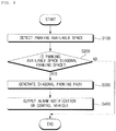
- the present invention has been made in view of the above problems, and it is one object of the present invention to provide a parking assistant system, which determines whether an available parking space is a diagonal parking space, and then determines a diagonal parking path for the vehicle to enter the diagonal parking space.
- the objects are achieved by the independent claim.
- Dependent claims refer to preferred embodiments.
- a parking assistant system including: an object detection apparatus configured to generate information on an object located outside a vehicle; and a controller configured to, when it is determined, based on the information, an available parking space is a diagonal parking space, generate a diagonal parking path for the vehicle to enter the available parking space.
- the present invention also relates to a parking assistant system for use in a vehicle, the parking assistant system comprises an object detection apparatus configured to generate information on an object located outside a vehicle; and a controller configured to, when it is determined, based on the information, an available parking space is a diagonal parking space, generate a diagonal parking path for the vehicle to enter the available parking space.
- an object detection apparatus configured to generate information on an object located outside a vehicle
- a controller configured to, when it is determined, based on the information, an available parking space is a diagonal parking space, generate a diagonal parking path for the vehicle to enter the available parking space.
- the controller is further configured to, when it is determined that there is a plurality of parking spaces including the available parking space and arranged in one direction, determine whether the available parking space is a diagonal parking space, based on a side parking line of the available parking space and a reference line.
- the reference line is a line formed in a direction in which the plurality of parking spaces is arranged.
- the controller is further configured to generate the reference line based on vertices of the plurality of parking spaces.
- the controller is further configured to, when it is determined that an angle between a side parking line and a reference line is an acute or obtuse angle, determine that the available parking space is a diagonal parking space.
- the controller is further configured to, when it is determined that a different vehicle is parked beside the available parking space and that an angle between a line formed in an overall length direction of the different vehicle and a reference line is an acute or obtuse angle, determine that the available parking space is a diagonal parking space.
- the object detection apparatus comprises a side sensor configured to detect an object located on a side of the vehicle.
- the object detection apparatus comprises a diagonal sensor configured to detect an object located in a diagonal direction of the vehicle.
- the controller is further configured to, when it is determined that a different vehicle is parked beside the available parking space and that there is an area which is not sensed by the side sensor but sensed by the diagonal sensor due to the presence of the different vehicle, determine that the available parking space is a diagonal parking space.
- the controller is further configured to, when it is determined based on the information that there is a plurality of parking paths for the vehicle to enter the available parking space, select one of the plurality of parking paths based on a user input.
- the controller is further configured to, in response to the selection of one of the plurality of parking paths, adjust a scale of a screen, preferably an Around View Monitoring (AVM) screen, displayed on a display unit of the vehicle based on a region occupied by the selected parking path.
- a scale of a screen preferably an Around View Monitoring (AVM) screen
- the controller is further configured to, when it is determined that there is a plurality of parking spaces including the available parking space and arranged in one direction, generate the diagonal parking path based on a location of the available parking space, a side parking line of the available parking space, a reference lane, and a location of the vehicle.
- the reference lane is formed in a direction in which the plurality of parking spaces is arranged and adjacent to the plurality of parking spaces.
- the controller is configured to select one of a reverse parking maneuver and a forward parking maneuver based on an angle between a side parking line and a reference lane and generate the diagonal parking path based on the selected parking maneuver.
- the controller is configured to select the forward parking maneuver in response to an acute angle between the side parking line and the reference lane, and select the reverse parking maneuver in response to an obtuse angle between the side parking line and the reference lane.
- the controller is further configured to, when it is determined that a different vehicle is parked beside the available parking space, select the forward parking maneuver in response to an acute angle between a line formed in an overall length direction of the different vehicle and the reference lane.
- the controller is further configured to, when it is determined that a different vehicle is parked beside the available parking space, select the reverse parking maneuver in response to an obtuse angle between the line formed in the overall length direction of the different vehicle and the reference lane.
- the controller is further configured to generate the diagonal parking path within a set range of an angle that is formed between a direction of the reference lane and a driving direction in which the vehicle travels straight forward within the reference lane with passing beside the available parking space.
- the controller is further configured to, when there is a plurality of available parking spaces respectively determined to be diagonal parking spaces select one of the plurality of available parking spaces based on a user input and generate a diagonal parking path for the vehicle to enter the selected available parking space.
- the controller is further configured to output a menu to an output unit of the vehicle to select a manual parking mode or an autonomous parking mode, select the manual parking mode or the autonomous parking mode based on a user input and in case of the selection of the autonomous parking mode perform a control operation so that the vehicle is parked along the diagonal parking path.
- the controller is further configured to, when it is determined that a driver of the vehicle takes hands off a steering wheel, select the autonomous parking mode.
- the controller is further configured to, in response to selection of the manual parking mode, output parking guide information to the output unit to guide the diagonal parking path.
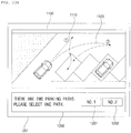
- the controller is further configured to, when it is determined that the vehicle is in a reference lane and that there is a plurality of available parking spaces existing on both sides of the reference lane and respectively determined to be diagonal parking spaces: determine at least one predicted parking space, based on locations and a tilt direction of the plurality of available parking spaces and a location and a moving direction of the vehicle (100), and output an image indicating the at least one predicted parking space to an output unit of the vehicle.
- the controller is further configured to output an image indicating parking spaces other than the predicted parking space from among the plurality of parking spaces to the output unit.
- the controller is further configured to turn on a turn signal light corresponding to a direction in which the predicted parking space is located, based on the locations and the tilt direction of the plurality of available parking spaces and the location and the driving direction of the vehicle.
- the embodiments of the present invention have one or more effects as follows.
- a vehicle as described in this specification may include an automobile and a motorcycle.
- a description will be given based on an automobile.
- a vehicle as described in this specification may include all of an internal combustion engine vehicle including an engine as a power source, a hybrid vehicle including both an engine and an electric motor as a power source, and an electric vehicle including an electric motor as a power source.
- the left side of the vehicle refers to the left side in the forward direction of the vehicle
- the right side of the vehicle refers to the right side in the forward direction of the vehicle
- FIGS. 1 to 7 are diagrams illustrating a vehicle having a parking assistant system according to the present invention.
- the vehicle according to the present invention will be described with reference to FIGS. 1 to 7 .
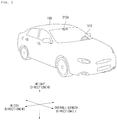
- FIG. 1 is a diagram of the external appearance of a vehicle according to an embodiment of the present invention.
- FIG. 2 is different angled views of a vehicle according to an embodiment of the present invention.
- FIGS. 3 and 4 are diagrams of the internal configuration of a vehicle according to an embodiment of the present invention.
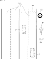
- FIGS. 5 and 6 are diagrams for explanation of objects according to an embodiment of the present invention.
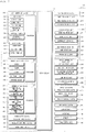
- FIG. 7 is a block diagram illustrating a vehicle according to an embodiment of the present invention.
- a vehicle 100 may include a plurality of wheels, which are rotated by a power source, and a steering input device 510 for controlling a driving direction of the vehicle 100.
- the vehicle 100 may include various driver assistant apparatuses.
- a driver assistant apparatus is a device that assists a driver based on information acquired from various sensors.
- the driver assistant apparatus may be referred to as an Advanced Driver Assistance System (ADAS).
- ADAS Advanced Driver Assistance System
- the vehicle 100 may include various lighting devices for vehicle.
- a lighting device for vehicle may include a head lamp, a brake lamp, a tail lamp, a turn signal lamp, a room lamp, etc.
- the lighting device for vehicle will be described mainly about a head lamp.
- aspects of the present invention is not limited thereto, and the lighting device for vehicle may be a rear combination lamp.
- the rear combination lamp includes a brake lamp and a trail lamp.
- the vehicle 100 may include a sensing device inside the vehicle 100, and a sensing device outside the vehicle 100.
- overall length means the length from the front end to the rear end of the vehicle 100
- the term “overall width” means the width of the vehicle 100
- the term “overall height” means the height from the bottom of the wheel to the roof.
- the term “overall length direction L” may mean the reference direction for the measurement of the overall length of the vehicle 100
- the term “overall width direction W” may mean the reference direction for the measurement of the overall width of the vehicle 100
- the term “overall height direction H” may mean the reference direction for the measurement of the overall height of the vehicle 100.
- the vehicle 100 may be an autonomous vehicle.
- the vehicle 100 may travel autonomously under the control of the controller 170.
- the vehicle 100 may travel autonomously based on vehicle driving information.
- the vehicle driving information may be information that is acquired by various units provided in the vehicle 100 during travelling of the vehicle 100.
- the vehicle driving information may be information used for controlling by the controller 170 or an operation system 700 to control the vehicle 100.
- the vehicle driving information may be a concept including at least one of: object information acquired by an object detection apparatus 300, information received by a communication apparatus 400, and a user input received by a user interface apparatus 200 or a driving manipulation apparatus 500.
- the object information may be information on the form, location, size, and color of a object sensed by the object detection apparatus 300.
- the object information may be information on a lane, an obstacle, a nearby vehicle, a pedestrian, a traffic light, a road structure, content of a traffic sign plate, etc.
- the information received by the communication apparatus 400 may be information transmitted and received by a device capable of performing communication.
- the information received by the communication apparatus 400 may include at least one of the following: information transmitted by a nearby vehicle; information transmitted by a mobile terminal; information transmitted by a traffic infrastructure, and information existing in a specific network.
- the traffic infrastructure may include a traffic light, and the traffic light may transmit information about a traffic signal.
- the vehicle driving information may include at least one of the following: navigation information; information on a control state of the vehicle 100; and location information of the vehicle 100.
- the vehicle driving information may include: information on a nearby vehicle which is transmitted by the nearby vehicle; information on a travel route; and map information.
- the controller 170 may determine: a type, location, and movement of an object in the vicinity of the vehicle 100; whether a line exists in the vicinity of the vehicle 100; whether a stopping area exists in the vicinity of the vehicle 100; a probability of collision between the vehicle 100 and an object; a distribution of pedestrians or bicycles in the vicinity of the vehicle 100; a type of a road in which the vehicle 100 is travelling; a state of a traffic light in the vicinity of the vehicle 100; and movement of the vehicle 100.
- Vehicle driving information may be acquired by at least one of the user interface apparatus 200, the object detection apparatus 300, the communication apparatus 400, the driving manipulation apparats 500, the navigation system 770, a sensing unit 120, an interface unit 130, and a memory 140.
- the vehicle driving information and may provide acquired information to the controller 170. Based on the vehicle driving information, the controller 170 may control the vehicle 100 to travel autonomously.
- Occupant information may include a driver's image acquired using an internal camera 220 or the driver's biometric information sensed using a biometric sensor 230.
- the occupant information may be an image about a location, a shape, an eye gaze, a face, a behavior, and a facial expression of an occupant, which is acquired using the internal camera 220.
- the biometric information may be information on temperature, pulse, and brainwaves of an occupant, which is acquired using the biometric sensing unit 230.
- the controller 170 may determine a location, a shape, an eye gaze, a face, a behavior, a facial expression, dozing, a health condition, and an emotional state of an occupant.
- the occupant information may be acquired using the occupant sensing unit 240, and provided to the controller 170.
- the occupant information may be a concept included in the aforementioned vehicle driving information.
- Vehicle state information may be information on a state of various units provided in the vehicle 100.
- the vehicle state information may include information on a operational state of the user interface apparatus 200, the object detection apparatus 300, the communication apparatus 400, the driving manipulation apparatus 500, a vehicle drive apparatus 600, and an operation system 700, and the vehicle state information may include information about whether there is an error in each unit.
- the controller 170 may determine whether a GPS signal of the vehicle 100 is properly received, whether there is an error in a sensor or camera provided in the vehicle 100, or whether each device provided in the vehicle 100 operates properly.
- the vehicle state information may be a concept included in the aforementioned vehicle driving information.
- Surrounding information may be information related to an environment in surroundings of the vehicle 100.
- the surrounding information may include information on an object located outside the vehicle 100.
- the surrounding information may be a concept including information related to an environment external to the vehicle 100 among object information acquired by the object detection apparatus 300, information received by the communication apparatus 400, and information acquired by the user interface apparatus 200.
- the controller 170 may determine a location and a type of an object outside the vehicle 100, and a type and a geographical feature of a road outside the vehicle 100.
- the surrounding information is a concept including the aforementioned vehicle driving information.
- a control mode of the vehicle 100 may indicate a subject which controls the vehicle 100.
- a control mode of the vehicle 100 may include: an autonomous mode in which the controller 170 or the operation system 700 included in the vehicle 100 controls the vehicle 100; a manual mode in which a driver in the vehicle 100 controls the vehicle 100; and a remote-control mode in which a device other than the vehicle 100 controls the vehicle 100.
- the controller 170 or the operation system 700 may control the vehicle 100 based on vehicle driving information. Accordingly, the vehicle 100 may travel without a user command received via the driving manipulation apparatus 500. For example, when the vehicle 100 is in the autonomous vehicle, the vehicle 100 may travel based on information, data, or a signal generated by a driving system 710, a parking-out system 710, and a parking system 750.
- the vehicle 100 When the vehicle 100 is in the manual mode, the vehicle 100 may be controlled based on a user command for at least one of steering, acceleration, and deceleration, which is received via the driving manipulation apparatus 500.
- the driving manipulation apparatus 500 may generate an input signal corresponding to a user command, and provide the input signal to the controller 170.
- the controller 170 may control the vehicle 100 based on the input signal provided from the driving manipulation apparatus 500.
- a device other than the vehicle 100 may control the vehicle 100.
- the vehicle 100 may receive a remote-control signal transmitted by another device via the communication apparatus 400.
- the vehicle 100 may be controlled based on a remote-control signal.
- the vehicle 100 may enter one of the autonomous mode, the manual mode, and the remote-control mode based on a user input received through the user interface apparatus 200.
- a control mode of the vehicle 100 may switch to one of the autonomous mode, the manual mode, and the remote-control mode based on at least one of occupant information, vehicle driving information, and vehicle state information.
- a control mode of the vehicle 100 may be switched from the manual mode to the autonomous mode, or vice versa, based on object information generated by the object detection apparatus 300.
- a control mode of the vehicle 100 may be switched from the manual mode to the autonomous mode, or vice versa, based on information received via the communication apparatus 400.
- the vehicle 100 may include the user interface apparatus 200, the objection detection apparatus 300, the communication apparatus 400, the manipulation apparatus 500, the vehicle drive apparatus 600, the operation system 700, a navigation system 770, a sensing unit 120, an interface 130, a memory 140, a controller 170, and a power supply unit 190.
- the parking system according to the present invention may constitute a part of a configuration provided in the vehicle 100.
- the parking assistant system according to the present invention may be a concept including the object detection apparatus 300 and the controller 170 provided in the vehicle 100.
- the parking assistant system according to the present invention may be a device having elements different from those of the vehicle 100.
- the parking assistant system according to the present invention may include an additional controller (not shown), an object detection apparatus (not shown), a user interface apparatus (not shown), an interface unit (not shown), and a power supply unit (not shown).
- the interface unit may receive information or a signal provided from the controller 170 or the object detection apparatus 300 of the vehicle 100, and transmit a control signal from the controller of the parking assistant system to at least one of the controller 170, the vehicle drive apparatus 600, and the user interface apparatus 200. Accordingly, even the controller of the parking assistant system is able to acquire information acquired by each element of the vehicle 100 and control each element of the vehicle 100.
- the parking assistant system according to the present invention is considered to be a constituent element of the vehicle 100.
- the user interface apparatus 200 is provided to support communication between the vehicle 100 and a user.
- the user interface apparatus 200 may receive a user input, and provide information generated in the vehicle 100 to the user.
- the vehicle 100 may enable User Interfaces (UI) or User Experience (UX) through the user interface apparatus 200.
- UI User Interfaces
- UX User Experience
- the user interface apparatus 200 may include an input unit 210, an internal camera 220, a biometric sensing unit 230, an output unit 250, and an interface processor 270.
- the user interface apparatus 200 may further include other components in addition to the aforementioned components, or may not include some of the aforementioned components.
- the input unit 210 is configured to receive a user command from a user, and data collected by the input unit 210 may be analyzed by the interface processor 270 and then recognized as a control command of the user.
- the input unit 210 may be disposed inside the vehicle 100.
- the input unit 210 may be disposed in a region of a steering wheel, a region of an instrument panel, a region of a seat, a region of each pillar, a region of a door, a region of a center console, a region of a head lining, a region of a sun visor, a region of a windshield, or a region of a window.
- the input unit 210 may include a voice input unit 211, a gesture input unit 212, a touch input unit 213, and a mechanical input unit 214.
- the voice input unit 211 may convert a voice input of a user into an electrical signal.
- the converted electrical signal may be provided to the interface processor 270 or the controller 170.
- the voice input unit 211 may include one or more microphones.
- the gesture input unit 212 may convert a gesture input of a user into an electrical signal.
- the converted electrical signal may be provided to the interface processor 270 or the controller 170.
- the gesture input unit 212 may include at least one selected from among an infrared sensor and an image sensor for sensing a gesture input of a user.
- the gesture input unit 212 may sense a three-dimensional (3D) gesture input of a user.
- the gesture input unit 212 may include a plurality of light emitting units for emitting infrared light, or a plurality of image sensors.
- the gesture input unit 212 may sense the 3D gesture input by employing a Time of Flight (TOF) scheme, a structured light scheme, or a disparity scheme.
- TOF Time of Flight
- the touch input unit 213 may convert a user's touch input into an electrical signal.
- the converted electrical signal may be provided to the interface processor 270 or the controller 170.
- the touch input unit 213 may include a touch sensor for sensing a touch input of a user.
- the touch input unit 210 may be formed integral with a display unit 251 to implement a touch screen.
- the touch screen may provide an input interface and an output interface between the vehicle 100 and the user.
- the mechanical input unit 214 may include at least one selected from among a button, a dome switch, a jog wheel, and a jog switch. An electrical signal generated by the mechanical input unit 214 may be provided to the interface processor 270 or the controller 170.
- the mechanical input unit 214 may be located on a steering wheel, a center fascia, a center console, a cockpit module, a door, etc.
- the occupant sensing unit 240 may sense an occupant inside the vehicle 100.
- the occupant sensing unit 240 may include an internal camera 220 and a biometric sensing unit 230.
- the internal camera 220 may acquire images of the inside of the vehicle 100.
- the processor 270 may sense a state of a user based on the images of the inside of the vehicle 100. For example, a sensed state of a user may be about a user's eye gaze, face, behavior, facial expression, and location.
- the interface processor 270 may determine the user's eye gaze, face, behavior, facial expression, and location.
- the interface processor 270 may determine the user's gesture based on an image of the inside of the vehicle 100.
- the determination made by the interface processor 270 based on the image of the inside of the vehicle 100 may be referred to as occupant information.
- the occupant information is information indicating a user's eye gaze direction, behavior, facial expression, and gesture.
- the interface processor 270 may provide the occupant information to the controller 170.
- the biometric sensing unit 230 may acquire biometric information of the user.
- the biometric sensing unit 230 may include a sensor for acquire biometric information of the user, and may utilize the sensor to acquire the user's finger print information, heart rate information, brain wave information, etc.
- the biometric information may be used to authorize the user or to determine the user's state.
- the interface processor 270 may determine a user's state based on a user's biometric information acquired by the biometric sensing unit 230.
- the user's state determined by the interface processor 270 may be referred to as occupant information.
- the occupant information is information indicating whether the user is in faint, dozing off, excited, or in an emergency situation.
- the interface processor 270 may provide the occupant information to the controller 170.
- the output unit 250 is configured to generate a visual, audio, or tactile output.
- the output unit 250 may include at least one selected from among a display unit 251, a sound output unit 252, and a haptic output unit 253.
- the display unit 251 may display graphic objects corresponding to various types of information.
- the display unit 251 may include at least one selected from among a Liquid Crystal Display (LCD), a Thin Film Transistor-Liquid Crystal Display (TFT LCD), an Organic Light-Emitting Diode (OLED), a flexible display, a 3D display, and an e-ink display.
- LCD Liquid Crystal Display
- TFT LCD Thin Film Transistor-Liquid Crystal Display
- OLED Organic Light-Emitting Diode
- the display unit 251 may form an inter-layer structure together with the touch input unit 213, or may be integrally formed with the touch input unit 213 to implement a touch screen.
- the display unit 251 may be implemented as a Head Up Display (HUD). When implemented as a HUD, the display unit 251 may include a projector module in order to output information through an image projected on a windshield or a window.
- HUD Head Up Display
- the display unit 251 may include a transparent display.
- the transparent display may be attached on the windshield or the window.
- the transparent display may display a predetermined screen with a predetermined transparency.
- the transparent display may include at least one selected from among a transparent Thin Film Electroluminescent (TFEL) display, an Organic Light Emitting Diode (OLED) display, a transparent Liquid Crystal Display (LCD), a transmissive transparent display, and a transparent Light Emitting Diode (LED) display.
- TFEL Thin Film Electroluminescent
- OLED Organic Light Emitting Diode
- LCD transparent Liquid Crystal Display
- LED transparent Light Emitting Diode
- the transparency of the transparent display may be adjustable.
- the user interface apparatus 200 may include a plurality of display units 251a to 251g.
- the display unit 251 may be disposed in a region of a steering wheel, a region 251a, 251b, or 251e of an instrument panel, a region 251d of a seat, a region 251f of each pillar, a region 251g of a door, a region of a center console, a region of a head lining, a region of a sun visor, a region 251c of a windshield, or a region 251h of a window.
- the sound output unit 252 converts an electrical signal from the interface processor 270 or the controller 170 into an audio signal, and outputs the audio signal. To this end, the sound output unit 252 may include one or more speakers.
- the haptic output unit 253 generates a tactile output.
- the tactile output is vibration.
- the haptic output unit 253 operates to vibrate a steering wheel, a safety belt, and seats 110FL, 110FR, 110RL, and 110RR so as to allow a user to recognize the output.
- the interface processor 270 may control the overall operation of each unit of the user interface apparatus 200.
- the user interface apparatus 200 may include a plurality of interface processors 270 or may not include the interface processor 270.
- the user interface apparatus 200 may operate under the control of the controller 170 or a processor of a different device inside the vehicle 100.
- the user interface apparatus 200 may be referred to as a multimedia device for vehicle.
- the user interface apparatus 200 may operate under the control of the controller 170.
- the objection detection apparatus 300 is configured to detect an object located outside the vehicle 100.
- the object may include various objects related to travelling of the vehicle 100.
- an object o may include a lane OB10, a line distinguishing the lane OB10, a nearby vehicle OB11, a pedestrian OB12, a two-wheeled vehicle OB13, a traffic signal OB14 and OB15, a curb for distinguishing a sidewalk a light, a road, a structure, a bump, a geographical feature, an animal, etc.
- the lane OB10 may be a driving lane in which the vehicle 100 is traveling, a lane next to the driving lane, and a lane in which an opposing vehicle is travelling.
- the lane OB10 may include left and right lines that define the lane.
- the nearby vehicle OB11 may be a vehicle that is travelling in the vicinity of the vehicle 100.
- the nearby vehicle OB11 may be a vehicle located within a predetermined distance from the vehicle 100.
- the nearby vehicle OB11 may be a vehicle that is preceding or following the vehicle 100.
- the nearby vehicle OB11 may be a vehicle travelling on a lane next to a lane in which the vehicle 100 is travelling.
- the pedestrian OB12 may be a person in the vicinity of the vehicle 100.
- the pedestrian OB12 may be a person located within a predetermined distance from the vehicle 100.
- the pedestrian OB12 may be a person on a sidewalk or on the roadway.
- the two-wheeled vehicle OB13 is a vehicle that is in the vicinity of the vehicle 100 and moves using two wheels.
- the two-wheeled vehicle OB13 may be a vehicle that has two wheels located within a predetermined distance from the vehicle 100.
- the two-wheeled vehicle OB13 may be a motorcycle or a bike on a sidewalk or the roadway.
- the traffic signal OB14 and OB15 may include a traffic light OB15, a traffic sign plate OB14, and a pattern or text painted on a road surface.
- the light may be light generated by a lamp provided in the nearby vehicle OB11.
- the light may be light generated by a street light.
- the light may be solar light.
- the road may include a road surface, a curve, and slopes, such as an upward slope and a downward slope.
- the geographical feature may include a mountain, a hill, etc.
- the structure may be a body located around the road in the state of being fixed onto the ground.
- the structure may include a streetlight, a roadside tree, a building, a traffic light, a bridge, a curb, a guardrail, etc.
- the object may be classified as a movable object or a stationary object.
- the movable object is an object which is capable of moving.
- the movable object may be a concept including a nearby vehicle and a pedestrian.
- the stationary object is an object which is incapable of moving.
- the stationary object may be a concept including a traffic signal, a road, a structure, and a line.
- the object detection apparatus 200 may detect an obstacle located outside the vehicle 100.
- the obstacle may be an object, a puddle on the road, an uphill start point, a downhill start point, an inspection pit, a bump, and a curb.
- the object may be an object having a volume and a mass.
- the objection detection apparatus 300 may include a camera 310, a Radio Detection and Ranging (RADAR) 320, a Light Detection and Ranging (LIDAR) 330, an ultrasonic sensor 340, an infrared sensor 350, and a detection processor 370.
- RADAR Radio Detection and Ranging
- LIDAR Light Detection and Ranging
- the objection detection apparatus 300 may further include other components in addition to the aforementioned components, or may not include some of the aforementioned components.
- the camera 310 may be located at an appropriate position outside the vehicle 100 in order to acquire images of the outside of the vehicle 100.
- the camera 310 may provide an acquired image to the detection processor 370.
- the camera 310 may be a mono camera, a stereo camera 310a, an Around View Monitoring (AVM) camera 310b, or a 360-degree camera.
- AVM Around View Monitoring
- the camera 310 may be disposed near a front windshield in the vehicle 100 in order to acquire images of the front of the vehicle 100.
- the camera 310 may be disposed around a front bumper or a radiator grill.
- the camera 310 may be disposed near a rear glass in the vehicle 100 in order to acquire images of the rear of the vehicle 100.
- the camera 310 may be disposed around a rear bumper, a trunk, or a tailgate.
- the camera 310 may be disposed near at least one of the side windows in the vehicle 100 in order to acquire images of the side of the vehicle 100.
- the camera 310 may be disposed around a side mirror, a fender, or a door.
- the RADAR 320 may include an electromagnetic wave transmission unit and an electromagnetic wave reception unit.
- the RADAR 320 may be realized as a pulse RADAR or a continuous wave RADAR depending on the principle of emission of an electronic wave.
- the RADAR 320 may be realized as a Frequency Modulated Continuous Wave (FMCW) type RADAR or a Frequency Shift Keying (FSK) type RADAR depending on the waveform of a signal.
- FMCW Frequency Modulated Continuous Wave
- FSK Frequency Shift Keying
- the RADAR 320 may detect an object through the medium of an electromagnetic wave by employing a time of flight (TOF) scheme or a phase-shift scheme, and may detect a location of the detected object, the distance to the detected object, and the speed relative to the detected object.
- TOF time of flight
- the RADAR 320 may be located at an appropriate position outside the vehicle 100 in order to sense an object located in front of the vehicle 100, an object located to the rear of the vehicle 100, or an object located to the side of the vehicle 100.
- the LIDAR 330 may include a laser transmission unit and a laser reception unit.
- the LIDAR 330 may be implemented by the TOF scheme or the phase-shift scheme.
- the LIDAR 330 may be implemented as a drive type LIDAR or a non-drive type LIDAR.
- the LIDAR 300 may rotate by a motor and detect an object in the vicinity of the vehicle 100.
- the LIDAR 300 may utilize a light steering technique to detect an object located within a predetermined distance from the vehicle 100.
- the LIDAR 330 may detect an object through the medium of laser light by employing the TOF scheme or the phase-shift scheme, and may detect a location of the detected object, the distance to the detected object, and the speed relative to the detected object.
- the LIDAR 330 may be located at an appropriate position outside the vehicle 100 to sense an object located in front of the vehicle 100, an object located to the rear of the vehicle 100, or an object located to the side of the vehicle 100.
- the ultrasonic sensor 340 may include an ultrasonic wave transmission unit and an ultrasonic wave reception unit.
- the ultrasonic sensor 340 may detect an object based on an ultrasonic wave, and may detect a location of the detected object, the distance to the detected object, and the speed relative to the detected object.
- the ultrasonic sensor 340 may be located at an appropriate position outside the vehicle 100 to detect an object located in front of the vehicle 100, an object located to the rear of the vehicle 100, and an object located to the side of the vehicle 100.
- the infrared sensor 350 may include an infrared light transmission unit and an infrared light reception unit.
- the infrared sensor 340 may detect an object based on infrared light, and may detect a location of the detected object, the distance to the detected object, and the speed relative to the detected object.
- the infrared sensor 350 may be located at an appropriate position outside the vehicle 100 to sense an object located in front of the vehicle 100, an object located to the rear of the vehicle 100, or an object located to the side of the vehicle 100.
- the detection processor 370 may control the overall operation of each unit included in the objection detection apparatus 300.
- the detection processor 370 may detect and track an object based on acquired images. Using an image processing algorithm, the detection processor 370 may: calculate the distance to the object and the speed relative to the object; determine an object's type, location, shape, color, and expected route; and determine content of a detected text.
- the detection processor 370 may detect and track an object based RADAR, Radio Detection and Ranging which is formed as the result of reflection a transmission electromagnetic wave by the object. Based on the electromagnetic wave, the detection processor 370 may, for example, calculate the distance to the object and the speed relative to the object.
- the detection processor 370 may detect and track an object based on a reflection laser light which is formed as the result of reflection of transmission laser by the object. Based on the laser light, the detection processor 370 may, for example, calculate the distance to the object and the speed relative to the object.
- the detection processor 370 may detect and track an object based on a reflection ultrasonic wave which is formed as the result of reflection of a transmission ultrasonic wave by the object. Based on the ultrasonic wave, the detection processor 370 may, for example, calculate the distance to the object and the speed relative to the object.
- the detection processor 370 may detect and track an object based on reflection infrared light which is formed as the result of reflection of transmission infrared light by the object. Based on the infrared light, the detection processor 370 may, for example, calculate the distance to the object and the speed relative to the object.
- the detection processor 370 may generate object information based on at least one of the following: an image acquired using the camera 310, a reflected electromagnetic wave received using the RADAR 320, a reflected laser beam received using the LIDAR 330, a reflected ultrasonic wave received using the ultrasonic sensor 340, and a reflected infrared light received using the infrared sensor 350.
- Object information may be information on a type, a location, a size, a shape, a color, a route, and a speed of an object in the vicinity of the vehicle 100, and content of a detected text.
- the object information may indicate the following: whether there is a lane in the vicinity of the vehicle 100; whether nearby vehicles are travelling at a time when the vehicle 100 is in a stop; whether there is a space available to park in the vicinity of the vehicle 100; a probability that the vehicle 100 collides with an object; a location of any pedestrian or bicycle in the vicinity of the vehicle 100; a type of the roadway on which the vehicle 100 is travelling; the current traffic signal indicated by a traffic light in the vicinity of the vehicle 100; and movement of the vehicle.
- the object information may be included in vehicle driving information.
- the detection processor 370 may provide generated object information to the controller 170.
- the objection detection apparatus 300 may include a plurality of detection processors 370 or may not include the processor 370.
- each of the camera 310, the RADAR 320, the LIDAR 330, the ultrasonic sensor 340, and the infrared sensor 350 may include an individual processor.
- the objection detection apparatus 300 may operate under the control of the controller 170 or a processor inside the vehicle 100.
- the communication apparatus 400 is configured to perform communication with an external device.
- the external device may be one of a nearby vehicle, a mobile terminal, and a server.
- the communication apparatus 400 may include at least one selected from among a transmission antenna, a reception antenna, a Radio Frequency (RF) circuit capable of implementing various communication protocols, and an RF device.
- RF Radio Frequency
- the communication apparatus 400 may include a short-range communication unit 410, a location information unit 420, a V2X communication unit 430, an optical communication unit 440, a broadcast transmission and reception unit 450, an Intelligent Transport Systems (ITS) communication unit 460, and a communication processor 470.
- a short-range communication unit 410 may include a short-range communication unit 410, a location information unit 420, a V2X communication unit 430, an optical communication unit 440, a broadcast transmission and reception unit 450, an Intelligent Transport Systems (ITS) communication unit 460, and a communication processor 470.
- ITS Intelligent Transport Systems
- the communication apparatus 400 may further include other components in addition to the aforementioned components, or may not include some of the aforementioned components.
- the short-range communication unit 410 is configured to perform short-range communication.
- the short-range communication unit 410 may support short-range communication using at least one selected from among BluetoothTM, Radio Frequency Identification (RFID), Infrared Data Association (IrDA), Ultra-WideBand (UWB), ZigBee, Near Field Communication (NFC), Wireless-Fidelity (Wi-Fi), Wi-Fi Direct, and Wireless USB (Wireless Universal Serial Bus).
- RFID Radio Frequency Identification
- IrDA Infrared Data Association
- UWB Ultra-WideBand
- ZigBee Near Field Communication
- NFC Near Field Communication
- Wi-Fi Wireless-Fidelity
- Wi-Fi Direct Wireless USB (Wireless Universal Serial Bus).
- the short-range communication unit 410 may form wireless area networks to perform short-range communication between the vehicle 100 and at least one external device.
- the location information unit 420 is configured to acquire location information of the vehicle 100.
- the location information unit 420 may include at least one of a Global Positioning System (GPS) module, a Differential Global Positioning System (DGPS) module, and a Carrier phase Differential GPS (CDGPS) module.
- GPS Global Positioning System
- DGPS Differential Global Positioning System
- CDGPS Carrier phase Differential GPS
- the location information unit 420 may acquire GPS information using a GPS module.
- the location information unit 420 may transfer the acquired GPS information to the controller 170 or the communication processor 470.
- the GPS information acquired by the location information unit 420 may be used for autonomous travelling of the vehicle 100. For example, based on GPS information and navigation information acquired using the navigation system 770, the controller 170 may control the vehicle 100 to travel autonomously.
- the V2X communication unit 430 is configured to perform wireless communication between a vehicle and a server (that is, vehicle to infra (V2I) communication), wireless communication between a vehicle and a nearby vehicle (that is, vehicle to vehicle (V2V) communication), or wireless communication between a vehicle and a pedestrian (that is, vehicle to pedestrian(V2P) communication).
- the V2X communication unit 430 may include a radio frequency (RF) circuit that is capable of implementing protocols for the V2I communication, the V2V communication, and V2P communication.
- RF radio frequency
- the optical communication unit 440 is configured to perform communication with an external device through the medium of light.
- the optical communication unit 440 may include a light emitting unit, which converts an electrical signal into an optical signal and transmits the optical signal to the outside, and a light receiving unit which converts a received optical signal into an electrical signal.
- the light emitting unit may be integrally formed with a lamp provided included in the vehicle 100.
- the broadcast transmission and reception unit 450 is configured to receive a broadcast signal from an external broadcasting management server or transmit a broadcast signal to the broadcasting management server through a broadcasting channel.
- the broadcasting channel may include a satellite channel, and a terrestrial channel.
- the broadcast signal may include a TV broadcast signal, a radio broadcast signal, and a data broadcast signal.
- the ITS communication unit 460 performs communication with a server that provides an intelligent traffic system.
- the ITS communication unit 460 may receive information on various traffic situations from the server of the intelligence traffic system.
- Information on a traffic situation may include a level of traffic congestion, a traffic situation on each road, and an amount of traffics in each area.
- the communication processor 470 may control the overall operation of each unit of the communication apparatus 400.
- Vehicle driving information may include information received using at least one of the short-range communication unit 410, the location information unit 420, the V2X communication unit 430, the optical communication unit 440, and the broadcast transmission and reception unit 450.
- vehicle driving information may include information received from a nearby vehicle, the information which is about a location, a model, route, speed, various sensed values, etc. of a nearby vehicle.
- the controller 170 may acquire information on various objects in the vicinity of the vehicle 100, even through the vehicle 100 does not include an additional sensor.
- the communication apparatus 400 may include a plurality of communication processors 470, or may not include a communication processor 470.
- the communication apparatus 400 may operate under the control of the controller 170 or a processor of a device inside the vehicle 100.
- the communication apparatus 400 may implement a vehicle multimedia device, together with the user interface apparatus 200.
- the vehicle multimedia device may be referred to as a telematics device or an Audio Video Navigation (AVN) device.
- APN Audio Video Navigation
- the communication apparatus 400 may operate under the control of the controller 170.
- the driving manipulation apparatus 500 is configured to receive a user input for driving the vehicle 100.
- the vehicle 100 may operate based on a signal provided by the driving manipulation apparatus 500.
- the driving manipulation apparatus 500 may include a steering input device 510, an acceleration input device 530, and a brake input device 570.
- the steering input device 510 may receive a user command for steering the vehicle 100.
- the user command for steering may be a command corresponding to a specific steering angle.
- a user command for steering may correspond to 45 degrees to right.
- the steering input device 510 may take the form of a wheel to enable a steering input through the rotation thereof.
- the steering input device 510 may be referred to as a steering wheel or a handle.
- the steering input device may be provided as a touchscreen, a touch pad, or a button.
- the acceleration input device 530 may receive a user input for acceleration of the vehicle 100.
- the brake input device 570 may receive a user input for deceleration of the vehicle 100.
- Each of the acceleration input device 530 and the brake input device 570 may take the form of a pedal.
- the acceleration input device or the break input device may be configured as a touch screen, a touch pad, or a button.
- the driving manipulation apparatus 500 may operate under the control of the controller 170.
- the vehicle drive apparatus 600 is configured to electrically control the operation of various devices of the vehicle 100.
- the vehicle drive apparatus 600 may include a power train drive unit 610, a chassis drive unit 620, a door/window drive unit 630, a safety apparatus drive unit 640, a lamp drive unit 650, and an air conditioner drive unit 660.
- the vehicle drive apparatus 600 may further include other components in addition to the aforementioned components, or may not include some of the aforementioned components.
- the vehicle drive apparatus 600 may include a processor. Each unit of the vehicle drive apparatus 600 may include its own processor.
- the power train drive unit 610 may control the operation of a power train.
- the power train drive unit 610 may include a power source drive unit 611 and a transmission drive unit 612.
- the power source drive unit 611 may control a power source of the vehicle 100.
- the power source drive unit 611 may perform electronic control of the engine. As such the power source drive unit 611 may control, for example, the output torque of the engine. The power source drive unit 611 may adjust the output toque of the engine under the control of the controller 170.
- the power source drive unit 611 may control the motor.
- the power source drive unit 610 may control, for example, the RPM and toque of the motor under the control of the controller 170.
- the transmission drive unit 612 may control a transmission.
- the transmission drive unit 612 may adjust the state of the transmission.
- the transmission drive unit 612 may adjust a state of the transmission to a drive (D), reverse (R), neutral (N), or park (P) state.
- the transmission drive unit 612 may adjust a gear-engaged state to the drive position D.
- the chassis drive unit 620 may control the operation of a chassis.
- the chassis drive unit 620 may include a steering drive unit 621, a brake drive unit 622, and a suspension drive unit 623.
- the steering drive unit 621 may perform electronic control of a steering apparatus provided inside the vehicle 100.
- the steering drive unit 621 may change the driving direction of the vehicle 100.
- the brake drive unit 622 may perform electronic control of a brake apparatus provided inside the vehicle 100. For example, the brake drive unit 622 may reduce the speed of the vehicle 100 by controlling the operation of a brake located at a wheel.
- the brake drive unit 622 may control a plurality of brakes individually.
- the brake drive unit 622 may apply a different degree-braking force to each wheel.
- the suspension drive unit 623 may perform electronic control of a suspension apparatus inside the vehicle 100. For example, when the road surface is uneven, the suspension drive unit 623 may control the suspension apparatus so as to reduce the vibration of the vehicle 100.
- the suspension drive unit 623 may control a plurality of suspensions individually.
- the door/window drive unit 630 may perform electronic control of a door apparatus or a window apparatus inside the vehicle 100.
- the door/window drive unit 630 may include a door drive unit 631 and a window drive unit 632.
- the door drive unit 631 may control the door apparatus.
- the door drive unit 631 may control opening or closing of a plurality of doors included in the vehicle 100.
- the door drive unit 631 may control opening or closing of a trunk or a tail gate.
- the door drive unit 631 may control opening or closing of a sunroof.
- the window drive unit 632 may perform electronic control of the window apparatus.
- the window drive unit 632 may control opening or closing of a plurality of windows included in the vehicle 100.
- the safety apparatus drive unit 640 may perform electronic control of various safety apparatuses provided inside the vehicle 100.
- the safety apparatus drive unit 640 may include an airbag drive unit 641, a safety belt drive unit 642, and a pedestrian protection equipment drive unit 643.
- the airbag drive unit 641 may perform electronic control of an airbag apparatus inside the vehicle 100. For example, upon detection of a dangerous situation, the airbag drive unit 641 may control an airbag to be deployed.
- the safety belt drive unit 642 may perform electronic control of a seatbelt apparatus inside the vehicle 100. For example, upon detection of a dangerous situation, the safety belt drive unit 642 may control passengers to be fixed onto seats 110FL, 110FR, 110RL, and 110RR with safety belts.
- the pedestrian protection equipment drive unit 643 may perform electronic control of a hood lift and a pedestrian airbag. For example, upon detection of a collision with a pedestrian, the pedestrian protection equipment drive unit 643 may control a hood lift and a pedestrian airbag to be deployed.
- the lamp drive unit 650 may perform electronic control of various lamp apparatuses provided inside the vehicle 100.
- the air conditioner drive unit 660 may perform electronic control of an air conditioner inside the vehicle 100. For example, when the inner temperature of the vehicle 100 is high, an air conditioner drive unit 660 may operate the air conditioner to supply cool air to the inside of the vehicle 100.
- the vehicle drive apparatus 600 may include a processor. Each unit of the vehicle dive device 600 may include its own processor.
- the vehicle drive apparatus 600 may operate under the control of the controller 170.
- the operation system 700 is a system for controlling the overall driving operation of the vehicle.
- the operation system 700 may operate in the autonomous driving mode.
- the operation system 700 may perform autonomous driving of the vehicle 100 based on location information of the vehicle 100 and navigation information.
- the operation system 700 may include the driving system 710, the parking-out system 740, and the parking system 750.
- the operation system 700 may further include other components in addition to the aforementioned components, or may not include some of the aforementioned component.
- the operation system 700 may include a processor. Each unit of the operation system 700 may include its own processor.
- the operation system 700 may be a subordinate concept of the controller 170.
- the operation system 700 may be a concept including at least one selected from among the user interface apparatus 200, the objection detection apparatus 300, the communication apparatus 400, the vehicle drive apparatus 600, and the controller 170.
- the driving system 710 may perform driving of the vehicle 100.
- the driving system 710 may perform autonomous driving of the vehicle 100 by providing a control signal to the vehicle drive apparatus 600 based on location information of the vehicle 100 and navigation information received from the navigation system 770.
- the driving system 710 may perform driving of the vehicle 100 by providing a control signal to the vehicle drive apparatus 600 based on object information received from the objection detection apparatus 300.
- the driving system 710 may perform driving of the vehicle 100 by providing a control signal to the vehicle drive apparatus 600 based on a signal received from an external device through the communication apparatus 400.
- the parking-out system 740 may perform an operation of pulling the vehicle 100 out of a parking space.
- the parking-out system 740 may perform an operation of pulling the vehicle 100 out of a parking space, by providing a control signal to the vehicle drive apparatus 600 based on location information of the vehicle 100 and navigation information received from the navigation system 770.
- the parking-out system 740 may perform an operation of pulling the vehicle 100 out of a parking space, by providing a control signal to the vehicle drive apparatus 600 based on object information received from the objection detection apparatus 300.
- the parking-out system 740 may perform an operation of pulling the vehicle 100 out of a parking space, by providing a control signal to the vehicle drive apparatus 600 based on a signal received from an external device.
- the parking system 750 may perform an operation of parking the vehicle 100 in a parking space.
- the parking system 750 may perform an operation of parking the vehicle 100 in a parking space, by providing a control signal to the vehicle drive apparatus 600 based on location information of the vehicle sd100 and navigation information received from the navigation system 770.
- the parking system 750 may perform an operation of parking the vehicle 100 in a parking space, by providing a control signal to the vehicle drive apparatus 600 based on object information received from the objection detection apparatus 300.
- the parking system 750 may perform an operation of parking the vehicle 100 in a parking space, by providing a control signal to the vehicle drive apparatus 600 based on a signal received from an external device.
- the navigation system 770 may provide navigation information.
- the navigation information may include at least one selected from among map information, information on a set destination, information on a route to the set destination, information on various objects along the route, lane information, and information on a current location of the vehicle.
- the navigation system 770 may include a memory and a processor.
- the memory may store navigation information.
- the processor may control the operation of the navigation system 770.
- the navigation system 770 may update pre-stored information by receiving information from an external device through the communication apparatus 400.
- the navigation system 770 may be classified as an element of the user interface apparatus 200.
- the sensing unit 120 may sense the state of the vehicle.
- the sensing unit 120 may include an attitude sensor (for example, a yaw sensor, a roll sensor, or a pitch sensor), a collision sensor, a wheel sensor, a speed sensor, a gradient sensor, a weight sensor, a heading sensor, a yaw sensor, a gyro sensor, a position module, a vehicle forward/reverse movement sensor, a battery sensor, a fuel sensor, a tire sensor, a steering sensor based on the rotation of the steering wheel, an in-vehicle temperature sensor, an in-vehicle humidity sensor, an ultrasonic sensor, an illumination sensor, an accelerator pedal position sensor, and a brake pedal position sensor.
- an attitude sensor for example, a yaw sensor, a roll sensor, or a pitch sensor
- a collision sensor for example, a yaw sensor, a roll sensor, or a pitch sensor
- a wheel sensor for example, a speed sensor, a gradient sensor
- the sensing unit 120 may acquire sensing signals with regard to, for example, vehicle attitude information, vehicle collision information, vehicle direction information, vehicle location information (GPS information), vehicle angle information, vehicle speed information, vehicle acceleration information, vehicle tilt information, vehicle forward/reverse movement information, battery information, fuel information, tire information, vehicle lamp information, in-vehicle temperature information, in-vehicle humidity information, steering-wheel rotation angle information, ambient illumination information, information about the pressure applied to an accelerator pedal, and information about the pressure applied to a brake pedal.
- Information acquired by the sensing unit 120 may be included in vehicle driving information.
- the sensing unit 120 may further include, for example, an accelerator pedal sensor, a pressure sensor, an engine speed sensor, an Air Flow-rate Sensor (AFS), an Air Temperature Sensor (ATS), a Water Temperature Sensor (WTS), a Throttle Position Sensor (TPS), a Top Dead Center (TDC) sensor, and a Crank Angle Sensor (CAS).
- AFS Air Flow-rate Sensor
- ATS Air Temperature Sensor
- WTS Water Temperature Sensor
- TPS Throttle Position Sensor
- TDC Top Dead Center
- CAS Crank Angle Sensor
- the interface 130 may serve as a passage for various kinds of external devices that are connected to the vehicle 100.
- the interface 130 may have a port that is connectable to a mobile terminal and may be connected to the mobile terminal via the port. In this case, the interface 130 may exchange data with the mobile terminal.
- the interface 130 may serve as a passage for the supply of electrical energy to a mobile terminal connected thereto.
- the interface 130 may provide electrical energy, supplied from the power supply unit 190, to the mobile terminal under the control of the controller 170.
- the memory 140 is electrically connected to the controller 170.
- the memory 140 may store basic data for each unit, control data for the operational control of each unit, and input/output data.
- the memory 140 may be any of various hardware storage devices, such as a ROM, a RAM, an EPROM, a flash drive, and a hard drive.
- the memory 140 may store various data for the overall operation of the vehicle 100, such as programs for the processing or control of the controller 170.
- the memory 140 may be integrally formed with the controller 170, or may be provided as an element of the controller 170.
- the power supply unit 190 may supply power required to operate each component under the control of the controller 170.
- the power supply unit 190 may receive power from, for example, a battery inside the vehicle 100.
- the controller 170 may control overall operation of each unit of the vehicle 100.
- the controller 170 may be referred to as an Electronic Control Unit (ECU).
- ECU Electronic Control Unit
- the controller 170 may perform autonomous driving of the vehicle 100 based on information acquired using a device provided in the vehicle 100. For example, the controller 170 may control the vehicle 100 based on navigation information provided from the navigation system 770 or information provided from the object detection apparatus 300 or the communication apparatus 400.
- the controller 170 may control the vehicle 100 based on an input signal corresponding to a user input that is received by the driving manipulation apparatus 500.
- the controller 170 may control the vehicle 100 based on a remote control signal received by the communication apparatus 400.
- processors and the controller 170 included in the vehicle 100 may be implemented using at least one selected from among Application Specific Integrated Circuits (ASICs), Digital Signal Processors (DSPs), Digital Signal Processing Devices (DSPDs), Programmable Logic Devices (PLDs), Field Programmable Gate Arrays (FPGAs), processors, controllers, micro-controllers, microprocessors, and electric units for the implementation of other functions.
- ASICs Application Specific Integrated Circuits
- DSPs Digital Signal Processors
- DSPDs Digital Signal Processing Devices
- PLDs Programmable Logic Devices
- FPGAs Field Programmable Gate Arrays
- processors controllers, micro-controllers, microprocessors, and electric units for the implementation of other functions.
- the parking assistant system may include the object detection apparatus 300 and the controller 170.
- the object detection apparatus 300 may detect an object located outside the vehicle 100.
- the object may be a concept including an object, the ground, a line painted in the ground, and a geographical feature.
- the object detection apparatus 300 may include at least one of a camera 310, a radar, a lidar, an ultrasonic sensor, and an infrared sensor.
- the object detection apparatus 300 may generate information on an object located outside the vehicle 100.
- the information on an object located outside the vehicle 100 may be referred to as object information.
- the object information may be an image captured by the camera 310.
- the object information may be location and distance information acquired using at least one of the radar, the lidar, the ultrasonic sensor, and the infrared sensor.
- the object detection apparatus 300 may provide generated object information to the controller 170. Based on the object information provided from the object detection apparatus 300, the controller 170 may determine whether an available parking space exists outside the vehicle 100.
- the available parking space is a space to which the vehicle 100 is allowed to move from the current location for parking. Based on the object information, the controller 170 may determine a location of the parking allowed space.
- the controller 170 may determine the space to be an available parking space. In addition, when it is found, based on location and distance information provided by various sensors, that there is an empty space between other vehicles into which the vehicle 100 is able to move for parking, the controller 170 may determine that an available parking space exists.
- FIG. 8 is a flowchart illustrating operation of a parking assistance system according to an embodiment of the present invention.
- the controller 170 may detect an available parking space based on object information in S100.
- the controller 170 may determine whether the available parking space is a diagonal parking space in S200.
- the controller 170 may determine whether the available parking space is a diagonal parking space based on side parking lines of the available parking space and a reference line.
- the reference line is a line formed in a direction in which the plurality of parking spaces is arranged.
- the reference line may be a line painted on the ground or may be a virtual line set by the controller 170.
- the controller 170 may generate the reference line based on vertices of the plurality of parking spaces.
- the reference line will be described later in more detail with reference to FIG. 10 .
- the diagonal parking space is a parking space tilted at a specific angle relative to a driving direction of the vehicle 100.
- the direction in which the diagonal parking space is tilted and the driving direction of the vehicle 100 are not parallel or perpendicular to each other, but form an acute or obtuse angle.
- the diagonal parking space may be a parking space tilted at approximately 45 degrees relative to a direction of a nearby road.
- the diagonal parking space will be described later in more detail with reference to FIG. 9 .
- the controller 170 may determine that the available parking space is a diagonal parking space.
- the controller 170 may determine that the available parking space is a diagonal parking space. A method of determining a diagonal parking space will be described later in more detail with reference to FIG. 11 .
- the object detection apparatus 300 may include a side sensor configured to detect an object located on a side of the vehicle 100, and a diagonal sensor configured to detect an object located in a diagonal direction of the vehicle 100.
- a sensor may be any one of a radar, a lidar, an ultrasonic sensor, and an infrared sensor.
- the side sensor may be a sensor arranged left or right to the vehicle 100. Accordingly, a direction in which the side sensor detects an object may be exactly or nearly perpendicular to the overall length direction of the vehicle.
- the diagonal sensor may be a sensor arranged in a forward diagonal direction or a backward diagonal direction of the vehicle 100.
- the diagonal sensor may be disposed at approximately 45 degrees relative to a direction for detection of an object or relative to the overall length direction of the vehicle 100.
- an angle between the direction in which the diagonal sensor senses an object and the overall length direction of the vehicle may be about 45 degrees.
- the controller 170 may determine that the available parking space is a diagonal parking space. Detailed description thereof will be provided with reference to FIG. 12 .
- the controller 170 may generate a diagonal parking path for the vehicle 100 to enter the available parking space in S300.
- the diagonal parking path is a path for the vehicle 100 to enter the available parking space.
- the diagonal parking path will be described later in more detail with reference to FIG. 9 .
- the controller 170 may output an alarm notification to guide the generated diagonal parking path, or may perform a control operation so that the vehicle is parked in the available parking space along the diagonal parking path in S400.
- the controller 170 may enter a manual parking mode or an autonomous parking mode based on a user input. If entering the manual parking mode, the controller 170 may output an alarm notification through the output unit 250 of the vehicle 100.
- the alarm notification may be at least one of an image displayed by the display unit 251 or sound output by the sound output unit 250.
- the alarm notification may be an arrow image indicating the diagonal parking path.
- the alarm notification may be voice that guide the vehicle 100 to move along the diagonal parking path.
- the controller 170 may control the vehicle drive apparatus 600 so that the vehicle 100 move along the diagonal parking path.
- FIG. 9 is a diagram illustrating a diagonal parking space and a diagonal parking path determined by a parking assistant system according to an embodiment of the present invention.
- a parking space may be a space defined by parking lines painted on the ground.
- the controller 170 may detect a parking line painted on the ground from an image captured by the camera 310, and determine a location of the parking space based on a location and a shape of the detected parking line.
- Types of a parking space may include a perpendicular parking space, a parallel parking space, and a diagonal parking space.
- the perpendicular parking space is a parking space which causes vehicles to be parked in a side direction.
- the parallel parking space is a parking space which causes vehicles to be parked in an overall length direction.
- the diagonal parking space is a parking space which causes vehicles to be parked at a specific angle and arranged in one direction.
- An available parking space is a parking space in which a vehicle is allowed to be parked.
- a parking space in which a different vehicle is parked is not an available parking space.
- a parking space which a vehicle is not allowed to enter despite of no vehicle parked therein is not an available parking space as well.
- the side parking line is a parking line existing on a side of a vehicle, when the vehicle plans to be parked in a parking space.
- the side parking line is a parking line corresponding to a long edge of a rectangular parking space.
- a parking space may be an inner space of a rectangle painted on the ground. If there are a plurality of rectangles respectively indicating parking spaces, a plurality of parking spaces is formed.
- the type of parking spaces is determined depending on the arrangement.
- the plurality of rectangles is arranged in a long-edge direction, a plurality of parking spaces is parallel parking spaces.
- the plurality of rectangles is arranged in a short-edge direction, a plurality of parking spaces is perpendicular parking spaces.
- the plurality of rectangles is arranged in a tilted manner, a plurality of parking spaces is diagonal parking spaces.
- the controller 170 may determine a location of an available parking space existing in surroundings of the vehicle 100. If a plurality of available parking spaces is detected in surroundings of the vehicle 100, the controller 170 may output a menu for selecting one of the plurality of available parking spaces. If a user input for selecting one of the plurality of available parking spaces is received through an input unit, the controller 170 may generate a parking path 20a along which the vehicle 100 enters into a selected available parking space 10a. If the selected available parking space 10a is a diagonal parking space, the parking path 20a along which the vehicle 100 enters into the selected available parking space 10a may be referred to as a diagonal parking path.
- parking spaces may be indicated by a plurality of side parking lines.
- a plurality of parking spaces is arranged in one direction.
- the type of parking spaces is determined depending on how much the side parking lines are tilted.
- the controller 170 may determine that a plurality of diagonal parking spaces exists.
- the controller 170 may determine that a parking space in which no other vehicle is parked is an available parking space. Based on a location of the available parking space and a location of the vehicle 100, the controller 170 may select an available parking space 10b which the vehicle 100 can enter by travelling the shortest distance. Based on the object information, the controller 170 may determine a parking path 20b for the vehicle 100 to enter the selected available parking space 10b.
- parking space may be indicated by a plurality of side parking lines and a reference line connecting end points of the side parking lines.
- the type of parking spaces is determined depending on how much the side parking lines are tilted.
- the controller 170 may determine that there is a plurality of diagonal parking spaces.
- the controller 170 may determine that a parking space in which no vehicle is parked is an available parking space.
- the controller 170 may generate a plurality of parking paths 20c and 20d along which the vehicle 100 needs to enter the plurality of available parking spaces 10c and 10d.
- the controller 170 may detect a reference line.
- a type of reference line and a detection method will be described with reference to FIG. 10 .
- FIG. 10 is a diagram illustrating a reference line determined by a parking assistant system according to an embodiment of the present invention.
- a diagonal parking space is a parking space tilted at a specific angle. To determine whether a specific parking space is a diagonal parking space, a reference line is required to determine whether the specific parking space is tilted at the specific angle.
- the reference line is a line indicating a direction in which a plurality of parking spaces is arranged. If the front-and-back direction of the plurality of parking spaces is tilted relative to a direction in which the plurality of parking space is arranged, the plurality of parking spaces is diagonal parking spaces. If the front-and-back direction of the plurality of parking spaces is the same as a direction in which the plurality of parking space is arranged, the plurality of parking spaces is parallel parking spaces. If the front-and-back direction of the plurality of parking spaces is perpendicular to a direction in which the plurality of parking space is arranged, the plurality of parking spaces is parallel parking spaces.
- the reference line may be a line painted on the ground, or may be a virtual line generated by the controller 170.
- a reference line is a line indicating a direction of a road adjacent to the parking spaces.
- the parking spaces are diagonal parking spaces.
- parking spaces are rectangles defined by parking lines.
- a reference line is a line connecting end points each located the same position in the respective rectangles.
- the controller 170 may generate a reference line based on vertices of the plurality of parking spaces.
- the generated reference line is a virtual line that is not displayed on the ground.
- a vertex of a parking space is a vertex of a rectangle indicating the corresponding parking space.
- the controller 170 may detect a rectangle indicating a parking space. If a plurality of rectangles is detected, the controller 170 may detect a vertex of each of the plurality of rectangles. The controller 170 may connect vertices each having the same position in the respective rectangles from among a plurality of detected vertices. The controller 170 may determine a straight line 12a connecting the vertices each having the same position in the respective rectangles is a virtual reference line. If the plurality of rectangles is arranged in one direction, a direction 11 in which the plurality of rectangles is arranged may correspond to a direction of the virtual reference line 12a. In this case, the virtual reference line 12a may indicate the direction 11 in which the plurality of parking spaces is arranged.
- parking spaces are indicated by a plurality of side parking lines.
- a reference line 12a is a line 12a connecting end points each having the same position in the respective side parking lines.
- An end point is considered as a concept included in a vertex.
- An endpoint of a side parking line is considered as a concept included in a vertex of a parking space.
- the controller 170 may generate the reference line 12a based on end points of the plurality of side parking lines.
- the reference line 12a is a virtual line that is not displayed on the ground.
- the controller 170 may detect a plurality of side parking lines indicating parking spaces.
- the controller 170 may detect an end point of each of the plurality of side parking lines.
- the controller 170 may connect end points each having the same position in the respective side parking lines.
- the controller 170 may determine that a straight line 12a connecting end points each having the same position in the respective side parking lines is a virtual reference line. If the plurality of side parking lines is arranged in one direction, the direction 11 in which the plurality of side parking lines is arranged may correspond to a direction of the virtual reference line 12a. In this case, the virtual reference line 12a may indicate the direction 11 in which the plurality of parking spaces is arranged.
- parking spaces are indicated by a plurality of side parking lines and an actual reference line 12b.
- the actual reference line 12b is a reference line painted on the ground.
- the actual reference line 12b is a line connecting end points of the plurality of side parking lines.
- the controller 170 may detect a reference line 12b formed in a direction in which a plurality of parking spaces is arranged.
- the actual reference line 12b may indicate the direction 11 in which the plurality of parking spaces is arranged.
- the controller 170 may determine whether the available parking space is a diagonal parking space. In addition, based on a reference line and an overall length direction of a other vehicle parked beside an available parking space, the controller 170 may determine whether the available parking space is a diagonal parking space. Hereinafter, a method by which the controller 170 determines whether an available parking space is a diagonal parking space will be described with reference to FIG. 11 .
- FIG. 11 is a diagram illustrating a method by which a parking assistant system according to an embodiment of the present invention detects a diagonal parking space.
- the controller 170 may determine that a rectangular parking space defined with parking lines exists on the right side of the vehicle 100.
- the controller 170 may determine a reference line 12a based on vertices of a plurality of parking spaces.
- a vertex of a parking space is a vertex of a rectangle indicating a parking space.
- the controller 170 may detect vertices of a plurality of rectangles indicating the plurality of parking spaces.
- the controller 170 may connect vertices each having the same position in the respective rectangles to form a straight line 12a.
- the controller 170 may generate a virtual reference line 12a connecting the vertices of the respective rectangles.
- the controller 170 may detect a side parking line 13 of an available parking space.
- the object information may be image information about the surroundings of the vehicle 100, the information acquired through the camera 310.
- the side parking line 13 is a parking line corresponding to a long edge of a rectangle indicating a parking space.
- the controller 170 may calculate an angle between the side parking line 13 of the available parking space and the reference line 12a. Based on the angle between the side parking line 13 of the available parking space and the reference line 12a, the controller 170 may determine a type of the available parking space.
- the controller 170 may determine that the available parking space is a diagonal parking space. If the angle between the side parking line 13 of the available parking space and the reference line 12a is an acute or obtuse angle, the available parking space is tilted at a specific angle relative to the reference line 12a.
- the controller 170 may determine that the available parking space is a parallel parking space. If the angle between the side parking line 13 of the available parking space and the reference line 12a is exactly or almost 90 degrees, the controller 170 may determine that the available parking space is a perpendicular parking space.
- the controller 170 may detect an actual reference line 12b painted on the ground and a side parking line 13, based on object information. When the actual reference line 12b is detected, the controller 170 may calculate an angle between the side parking line 13 of an available parking space and the actual reference line 12b. The controller 170 may determine a type of the available parking space based on an angle between the side parking line 13 of the available parking space and the actual reference line 12b. If it is determined that the angle between the side parking line 13 of the available parking space and the actual reference line 12b is an acute or obtuse angle, the controller 170 may determine that the available parking space is a diagonal parking space.
- the controller 170 may determine, based on an overall length direction 14 of the different vehicle and the reference line 12b, whether the available parking space is a diagonal parking space. Based on object information, the controller 170 may determine whether a different vehicle is parked beside the available parking space. Based on the object information, the controller 170 may determine the overall length direction 14 of the different vehicle parked beside the available parking space.
- the object information may be image information acquired through the camera 310, or information on a location, a size, and a shape of an object sensed by another sensor.
- the overall length direction 14 of the different vehicle is the front-and-back direction thereof.
- the controller 170 may determine an angle between the overall length direction 14 of the different vehicle parked beside the available parking space and the reference line 12b. If the angle between the overall length direction 14 of the different vehicle and the reference line 12b is an acute or obtuse angle, the controller 170 may determine that the available parking space existing beside the different vehicle is a diagonal parking space. Adjacent parking spaces are the same type, and thus, if a different vehicle is parked in a parking space adjacent to an available parking space, the controller 170 may determine a type of the available parking space based on a state of the different vehicle.
- the object detection apparatus 300 may include a side sensor configured to detect an object located on a side of the vehicle 100, and a diagonal sensor configured to detect an object located in a diagonal direction of the vehicle 100.
- the side sensor or the diagonal sensor may be any sensor capable of detecting an object of predetermined volume, and has no other limitation.
- the side sensor or the diagonal sensor may be any one of a radar, a lidar, an ultrasonic sensor, and an infrared sensor.
- the side sensor is disposed on the right or left side of the vehicle 100. As the side sensor detects an object in front thereof and is arranged on the right or left side of the vehicle 100, the controller 170 is able to detect an object located on the right or left side of the vehicle 100 by using the side sensor.
- the diagonal sensor is disposed in a diagonal direction of the vehicle 100.
- the diagonal direction is a concept including at least one of a right forward direction, a right backward direction, a left forward direction, and a left backward direction.
- the controller 170 is able to detect an object located in a diagonal direction of the vehicle 100.
- the controller 170 may determine whether a different vehicle is parked beside an available parking space. If it is determined that the different vehicle is parked beside the available parking space, the controller 170 may determine, based on information acquired by the diagonal sensor and the side sensor, whether the available parking space next to the different vehicle is a diagonal parking space.
- the controller 170 may determine whether there is an area which is not sensed by the side sensor but sensed by the diagonal sensor due to the presence of the different vehicle. If there is an area which is not sensed by the side sensor but sensed by the diagonal sensor due to the presence of the different vehicle, the controller 170 may determine that the available parking space next to the different vehicle is a diagonal parking space.
- the controller 170 may determine a shape of a parking space beside the different vehicle.
- the controller 170 may determine whether a shape of a parking space sensed by the diagonal sensor is identical to a shape of a parking space sensed by the side sensor. If it is determined that the shape of a parking space sensed by the diagonal sensor is identical to the shape of a parking space sensed by the side sensor, the controller 170 may determine that the parking space is a perpendicular or parallel parking space. In this case, there is no area which is not sensed by the side sensor but sensed by the diagonal sensor, and thus, the parking space is not a diagonal parking space.
- FIG. 12 is a diagram illustrating how a parking assistant system according to an embodiment of the present invention determines, by use of a sensor, whether an available parking space is a diagonal parking space.
- a diagonal sensor is disposed in a lateral backward direction of the vehicle 100.
- the diagonal sensor may be disposed in a lateral forward direction of the vehicle 100.
- a side sensor is disposed before the diagonal sensor in the vehicle 100.
- the side sensor and the diagonal sensor may be at the same location.
- the controller 170 may control the vehicle 100 to travel straight forward at a set speed.
- the controller 170 may control the vehicle 100 by transmitting a control signal to the vehicle drive apparatus 600.
- the controller 170 may control the vehicle 100 to travel in a direction of a reference line. If no parking line is detected from the ground, the controller 170 may determine, based on object information, a direction in which other vehicles 101 parked in one direction are arranged. In this case, based on the direction in which the parked other vehicles 101 are arranged, the controller 170 may generate a virtual straight line. The controller 170 may determine that a virtual straight line formed in the direction of arrangement of the parked other vehicles 101 is a reference line.
- the controller 170 may determine that the traffic line indicating the traffic lane is a reference line. In this case, if an angle between the traffic line indicating a traffic lane and the overall length direction of the different vehicle 101 is an acute or obtuse angle, the controller 170 may determine that a parking space beside the other vehicle 101 is a diagonal parking space. In this case, to search for an available parking space, the controller 170 moves the vehicle 100 along a direction of the traffic lane.
- a direction of a traffic lane is a direction in which the traffic lane elongates, and in which vehicles are required to move within the traffic lane according to laws.
- the controller 170 may determine a type of parking space based on space information detected by the side sensor and the diagonal sensor.
- the controller 170 may detect the different vehicle 101 using a side sensor located on the right side of the vehicle 100.
- an angle between the overall length direction of the vehicle 100 and the overall length direction of the different vehicle 101 is an acute or obtuse angle.
- an angle between the overall length direction of the different vehicle 101 and the direction for detection of the side sensor is an acute or obtuse angle.
- the angle between the overall length direction of the vehicle 101 and the direction for detection of the side sensor is an acute or obtuse angle, and thus, there is an area 102 which is not sensed by the side sensor due to the presence of the vehicle 101.
- the controller 170 may detect the vehicle 101 using the diagonal sensor. As a direction for detection of the diagonal sensor disposed in the right backward direction corresponds to the overall length direction of the vehicle 101, the area 102 not sensed by the side sensor may be sensed by the diagonal sensor. By comparing the shape of space sensed by the side sensor and the shape of a space sensed by the diagonal sensor, the controller 170 may determine whether there is an area 102 which is not sensed by the side sensor but sensed by the diagonal sensor. If the area 102 not sensed by the side sensor but sensed by the diagonal sensor exists beside the different vehicle 101, the controller 170 may determine that the blind spot 102 is created due to the different vehicle 101.
- the controller 170 may determine that the different vehicle 101 is parked in a diagonal direction. In this case, the controller 170 may determine that an available parking space next to the diagonally parked different vehicle 101 is a diagonal parking space.
- the controller 170 may determine that the vehicle 101 is parked in a perpendicular or parallel direction.
- the controller 170 may determine whether there is a diagonal parking space into which the vehicle 100 can enter by a reverse parking maneuver.
- the controller 170 may determine whether there is a diagonal parking space which the vehicle 100 can enter by performing a front parking maneuver.
- the controller 170 may determine one or more available parking spaces. Based on the object information, the controller 170 may determine whether the determined one or more available parking spaces are diagonal parking spaces. If it is determined that the one or more available parking spaces are diagonal parking spaces, the controller 170 may generate one or more paths along which the vehicle 100 moves to enter the one or more available parking spaces. Accordingly, there may be a plurality of available parking spaces and even a plurality of diagonal parking paths.
- the controller 170 may display a menu screen on the display unit 251 to select one of the plurality of available parking spaces and one of the diagonal parking paths. Based on a user input received through the input unit 210, the controller 170 may select one of the plurality of available parking spaces and one of the diagonal parking paths.
- the controller 170 may select one of the plurality of available parking spaces and one of the diagonal parking paths. For example, based on the vehicle driving information, the controller 170 may determine a space at the shortest distance from the vehicle 100, a space with the lowest parking difficulty, a space with the shortest parking time, or a space having the least probability of collision with an object among the plurality of available parking spaces, and then the controller 170 may select one available parking space.
- the controller 170 may determine that there is a plurality of parking paths to enter the available parking space. If it is determined that there is a plurality of parking paths to enter the available parking space, the controller 170 may display a menu screen on the display 251 to select one of the plurality of parking paths. Based on a user input or the vehicle driving information, the controller 170 may select one of the plurality of parking paths. Based on the vehicle driving information, the controller 170 may select a shortest path, a shortest parking path, a parking path with the lowest parking difficulty, and a parking path with the shortest parking time from the plurality of parking paths.
- the controller 170 may select, based on a user input or vehicle driving information, one of the plurality of parking paths. Based on the selected parking path, the controller 170 may adjust the scale of an Around View Monitor (AVM) displayed on the display unit 251 while parking the vehicle 100. Detailed description thereof will be provided with reference to FIG. 13B .
- AVM Around View Monitor
- FIGS. 13A and 13B are diagram illustrating a user interface that is provided a parking assistant system according to an embodiment of the present invention when there is a plurality of parking paths.
- the controller 170 may select one of the plurality of available parking spaces based on a user input.
- the controller 170 may determine, based on object information, whether there is a plurality of parking paths for the vehicle 100 to enter the selected available parking space.
- the controller 170 may display an AVM screen 1100 and a menu screen 1200 on the display unit 251, wherein the AVM screen 1100 shows the plurality of parking paths and the menu screen 1200 enables a user to select one of the plurality of parking paths,.
- the controller 170 may display both a first parking path and a second parking path on the AVM screen 1100.
- the controller 170 may display, on the menu screen 1200, a button 1201 for selecting the first parking path and a button 1202 for selecting the second path.
- the controller 170 may display, on the menu screen 1200, a path selection guide text. Based on a user input on the button 1201 for selecting the first parking path or the second button 1202 for selecting the second parking path, the controller 170 may select one of the plurality of parking paths.
- the controller 170 may adjust the scale of the AVM screen 1100 displayed on the display unit 251 of the vehicle 100 based on how large region is occupied by the selected parking path.
- a region occupied by a parking path indicates an area defined by a boundary that is generated by straightly connecting a start point and an end point of a parking path displayed on the AVM screen 1100.
- the controller 170 may adjust the scale of the AVM screen 1100 so that the region occupied by the selected parking path is entirely displayed on the AVM screen 1100. Accordingly, a user is able to see the whole parking path on the AVM screen 1100 without moving his/her perspective.
- the controller 170 selects the first parking path 1110 upon receipt of a user input on the button 1201 for selecting the first parking path 1110.
- the controller 170 adjusts the scale of the AVM screen 1100 so that the first parking path 1110 is entirely displayed on the AVM screen 1100.
- the controller 170 displays the first path 1110 on the AVM screen 1100, and, if the vehicle 100 moves, the controller 170 controls an image of the vehicle displayed on the AVM screen 1100 to move as well.
- the controller 170 selects the second parking path 1120 upon receipt of a user input on the button 1202 for selecting the second parking path 1120.
- the controller 170 may adjust the scale of the AVM screen 1100 so that the second path 1120 is entirely displayed on the AVM screen 1100.
- the controller 170 displays the second path 1120 on the AVM screen 1100, and, if the vehicle 100 moves, the controller 170 controls an image of the vehicle displayed on the AVM screen 1100 to move as well.
- the scale of the AVM screen 1100 which displays the first parking path 1110 is smaller than the scale of the AVM screen 1100 which displays the second parking path 1120.
- the controller 170 may generate a diagonal parking path based on a location of the available parking space, a side parking line, a reference lane, and a location of the vehicle 100.
- the reference lane is a lane which is formed in a direction of arrangement of the plurality of parking spaces and which is adjacent to the plurality of parking spaces.
- the reference lane may be a lane defined by lines on the ground or may be a virtual lane generated by the controller 170.
- a direction of the reference lane is a direction in which the reference lane elongates and in which the vehicle 100 has to move in the reference lane according to laws. For example, even when the vehicle 100 travels in a direction opposite to a direction designated by the laws, a direction of the reference lane is the direction designated by the laws.
- the controller 170 may generate a diagonal parking path based on a location of the available parking space, an overall length direction of a vehicle parked beside the available parking space, the reference lane, and a location of the vehicle 100.
- the controller 170 may select either a reverse parking maneuver or a forward parking maneuver based on an angle between a side parking line of the available parking space and the reference lane. Based on the selected parking maneuver, the controller 170 may generate a diagonal parking path.
- FIG. 14 is a diagram illustrating how a parking assistant system according to an embodiment of the present invention selects either a reverse parking maneuver or a forward parking maneuver.
- the controller 170 selects the forward parking maneuver.
- the controller 170 selects a reverse parking maneuver.
- a direction of the reference lane is assumed to be a left-to-right direction.
- the direction of the reference lane may correspond to a direction of reference lines 12a and 12b.
- the controller 170 may generate the reference line 12a which is a virtual straight line connecting end points of side parking lines 13 each indicating an available parking space.
- the controller 170 may determine that the available parking space is a diagonal parking space.
- the controller 170 may select an available parking space for the vehicle 100 to enter based on vehicle driving information or a user input. In the example of FIG. 14 , it is assumed that one available parking space is selected based on a user input.
- the controller 170 determines whether the vehicle 100 needs to perform a forward parking maneuver or a reverse parking maneuver.
- the controller 170 calculates an angle between the side parking line 13 and the reference lane based on a direction of the reference lane.
- the controller 170 determine an angle of the side parking line 13 relative to a direction to the right side of the reference lane.
- an angle between the side parking line 13 and the reference lane is an obtuse angle.
- the controller 170 determines that the vehicle 100 needs to perform a reverse parking maneuver. Accordingly, the controller 170 generates a parking path, along which the vehicle 100 can travel straight forward beside the selected available parking space and then reverse in the available parking space.
- the controller 170 may select one of parking maneuvers based on an overall length direction 14 of the other vehicle and the reference lane. If an angle between a line formed in the overall length direction 14 of the oher vehicle and the reference lane is an acute angle, the controller 170 may select a forward parking maneuver. If the angle between the line formed in the overall length direction 14 of the other vehicle and the reference lane is an obtuse angle, the controller 170 may select a reverse parking maneuver.
- the controller 170 may determine the overall length direction 14 of the different vehicle. Considering that a direction of the reference lane is to right, the controller 170 may determine an angle between a line formed in the overall length direction 14 of the different vehicle and the reference lane. As the angle between the line formed in the overall length direction 14 of the different vehicle and the reference lane is an obtuse angle, the controller 170 may determine that the vehicle 100 needs to perform a reverse parking maneuver to be parked in the available parking space. The controller 170 may generate a diagonal parking path based on the reverse parking maneuver.
- the controller 170 may detect a side parking line 13 on the left side of the vehicle 100, and a plurality of available parking spaces indicated by an actual reference line 12b.
- a direction of a reference lane may correspond to a direction of the actual reference line 12b.
- the controller 170 may determine that an angle between the side parking line 13 and the reference lane is an acute angle.
- the controller 170 may select a forward parking maneuver that the vehicle 100 needs to perform.
- the controller 170 may generate a diagonal parking path corresponding to the forward parking maneuver.
- the diagonal parking path corresponding to the forward parking maneuver is a path along which the vehicle 100 can enter an available parking space without reversing.
- FIG. 15 is a diagram illustrating a reverse diagonal parking path generated by a parking assistant system according to an embodiment of the present invention.
- the controller 170 may generate the diagonal parking path, wherein the diagonal parking path has a set range of an angle that is formed between a direction of the reference lane 11 and a driving direction 21 in which the vehicle 100 travels straight forward in the reference lane with passing beside the available parking space.
- the angle between the direction 11 of the reference lane and the driving direction 21 may fall within the set range.
- the set range is determined through experiments, and desirably as small as possible.
- the set range may be 0 to 6 degrees.
- parking accuracy may be improved if a driving direction of the vehicle and a direction of the reference lane form a small angle.
- the controller 170 may generate a diagonal parking path so that the angle between the driving direction in which the vehicle 100 travels straight forward in the reference lane and the direction of the reference lane falls within the set range.
- FIG. 16 is a diagram illustrating a user interface provided by a parking assistant system according to an embodiment of the present invention when there is a plurality of diagonal parking spaces.
- the controller 170 may select one of the plurality of available parking spaces based on a user input.
- the controller 170 may determine whether there is a plurality of available parking spaces determined to be diagonal parking spaces. If there is a plurality of available parking spaces determined to be diagonal parking spaces, the controller 170 may display a menu screen on the display unit 251 to select one of the plurality of available parking spaces.
- the menu screen may be an AVM screen 1100 which shows a vehicle and a plurality of available parking spaces.
- images respectively indicating the plurality of available parking spaces may be displayed.
- the images respectively indicating the plurality of available parking spaces may include different numbers, respectively. Accordingly, a user is able to select one of the plurality of available parking spaces.
- the controller 170 may select one of the plurality of available parking spaces based on a user input that is touching one of the plurality of available parking spaces displayed on the menu screen.
- the controller 170 may generate a diagonal parking path for the vehicle 100 to enter the selected available parking space.
- the controller 170 may generate the diagonal parking path based on a location of the vehicle 100 and a location and a tilting angle of the selected available parking space.
- the controller 170 may display an arrow image indicating the generated diagonal parking path on the AVM screen 1100.
- the controller 170 may output a menu to the output unit 250 of the vehicle 100 to select a manual parking mode or an autonomous parking mode.
- This menu may include a button for selecting the manual parking mode and a button for selecting the autonomous parking mode.
- the controller 170 may select the manual parking mode or the autonomous parking mode based on a user input corresponding to the output menu.
- the controller 170 may control the vehicle 100 to be parked along the diagonal parking path.
- the controller 170 may move the vehicle 100 by transmitting a control signal to the vehicle drive apparatus 600.
- the controller 170 may output parking guide information to the output unit 250 to guide the diagonal parking path.
- the parking guide information may include at least one of an arrow indicating the diagonal parking path, an image indicating the available parking space, and manipulation needed to be performed by a driver.
- the parking guide information may be displayed in various ways.
- the parking guide information may be the AVM screen of 1100 displayed on the display unit 251.
- an arrow corresponding to the diagonal parking path may be displayed on the AVM screen 1100.
- the parking guide information may be implemented in the form of Augmented Reality (AR) on a transparent display, such as a windshield or a window.
- AR Augmented Reality
- the parking guide information may include sound output to the sound output unit 250.
- the parking guide information may be guide voice for guiding the diagonal parking path.
- the controller 170 may change parking guide information displayed on the display unit 251, based on a driving direction and a location of the vehicle 100. For example, the vehicle 100 moves out of the diagonal parking path, the controller 170 may output an image indicating manipulation required for the driver to perform in order to return to the diagonal parking path.
- FIG. 17 is a diagram illustrating a user interface provided by a parking assistant system according to an embodiment of the present invention in order to perform autonomous parking.
- the controller 170 may display, on the display unit 251, a text for guiding a user about how to select autonomous parking.
- the controller 170 may output, to the display unit 251, a guide text indicating that autonomous parking will start upon hand-off from the handle.
- the controller 170 may output a text indicating that autonomous parking will start upon pressing of a specific button.
- the controller 170 may select the autonomous parking mode based on a user's preset behavior or preset input.
- the controller 170 may select the autonomous parking mode.
- an additional sensor may be disposed on the steering wheel.
- the sensor disposed on the steering wheel may sense contact of an object on the steering wheel. Based on detection information acquired by the sensor disposed on the steering wheel, the controller 170 may determine whether or not the driver put his/her hands on the steering wheel.
- the controller 170 may output a text to the transparent display 251c provided in the windshield to guide how to select autonomous parking.
- the controller 170 may display a selected available parking space in the form of AR.
- the controller 170 may output a text to the display 251a provided in the cluster of the vehicle 100 to guide how to select autonomous parking.
- the controller 170 may select the autonomous parking mode. When the autonomous parking mode is selected, the controller 170 may control the vehicle 100 to move along the diagonal parking path.
- FIGS. 18A , 18B , and 19 are diagrams illustrating guide information output by the parking assistant system according to an embodiment of the present invention in order to notify a predicted parking space.
- the controller 170 may determine at least one predicted parking space, based on locations and a tilt direction of the plurality of available parking spaces and a location and a driving direction of the vehicle 100.
- the controller 170 may output, to the output unit 250 of the vehicle 100, an image 31 indicating at least one predicted parking space.
- the controller 170 may determine whether the vehicle 100 is located in the reference lane and whether a plurality of available parking spaces determined to be diagonal parking spaces exists on both sides of the reference lane.
- a predicted parking space is one of the plurality of available parking spaces, in which the vehicle 100 is expected to be parked.
- the controller 170 may determine at least one predicted parking space, based on locations and a tilt direction of the plurality of available parking spaces and a location and a driving direction of the vehicle 100.
- the vehicle 100 is located in a reference lane, a driving direction of the vehicle 100 corresponds to a direction of a reference line, a plurality of available parking spaces is located in front of the vehicle 100, and a tilt direction of the plurality of available parking spaces is a direction in which the vehicle 10 needs to reverse for parking.
- the vehicle 100 is able to be parked in every available parking space without moving into other location or changing the driving direction. Because the vehicle 100 is able to be parked in every available parking space, the plurality of parking spaces may be all considered to be predicted parking spaces.
- the controller 170 may determine the aforementioned situation.
- the controller 170 may determine that every available parking space is a predicted parking space, based on locations and a tilt direction of the plurality of available parking spaces and a location and a driving direction of the vehicle 100.
- the controller 170 may display, on the display unit 251, an image indicating a predicted parking space.
- the image 31 may be a figure or line displayed in a part of the expected parking area.
- the controller 170 may display, on the AVM screen 110 output to the display unit 251, the image 31 indicating a predicted parking space.
- the image indicating a predicted parking space may be a rectangle 31 that covers a part of the predicted parking space.
- the controller 170 may display, on a transparent display provided in a windshield, the image indicating a predicted parking space.
- the image 31 indicating a predicted parking space may be a line 31 that passes a part of the predicted parking space. If an area selected by a user exists within an available parking space, the controller 170 may display, on the windshield, an image 31b in the form of AR. The controller 170 may display, on the windshield, an arrow that notifies a parking path for the vehicle 100 to enter an available parking space selected by the user.
- the controller 170 may output, to the output unit 250, an image indicating parking spaces other than the predicted parking space among the plurality of available parking spaces.
- the parking spaces other than the predicted parking space among the plurality of available parking spaces may be spaces in which the vehicle 100 is not expected to be parked.
- the vehicle 100 is located in a reference lane, a driving direction of the vehicle 100 is tilted at a specific angle to the left, a plurality of available parking spaces is located beside the vehicle 100, and a tilt direction of the plurality of available parking spaces is a direction in which the vehicle 100 needs to reverse to be parked.
- an available parking space on the left side of the vehicle 100 is not a predicted parking space.
- the available parking space on the left side of the vehicle 100 is a space in which the vehicle 100 needs to enter by performing a reverse parking maneuver.
- the vehicle 100 is directed toward an available parking space on the left side of the vehicle 100, the vehicle 100 is not able to enter the available parking space on the left side of the vehicle 100 by performing the reverse parking maneuver.
- the vehicle 100 is not able to enter an available parking space on the right side of the vehicle 100 by performing the reverse parking maneuver. Accordingly, only the available parking space on the right side of the vehicle 100 is a predicted parking space.
- the controller 170 may determine that only the available parking space on the right side of the vehicle 100 is a predicted parking space, based on respective locations and a tilt direction of the plurality of available parking spaces and a location and a driving direction of the vehicle 100.
- An image indicating a predicted parking space out of the plurality of available parking spaces is a first image, and an image indicating parking spaces other than the predicted parking space from among the plurality of available parking spaces is a second image.
- the controller 170 may output, to the display unit 251, the AVM screen 1100 which shows the plurality of available parking spaces.
- the controller 170 may display a second image 32 in one region of an available parking space on the left side of the vehicle 100, and a first image 31 on one region of an available parking space on the right side of the vehicle 100.
- the first image 31 and the second image 32 may be displayed with different colors.
- the first image 31 indicating the expected available parking space may be in green
- the second image 32 may be in red.
- the controller 170 may display the second image 32 in one region of the windshield.
- the controller 170 may display an image indicating the selected available parking space in red.
- the controller 170 may display, in the windshield, an arrow that notifies a parking path for the vehicle to enter the selected available parking space.
- the controller 170 may turn on a turn signal light corresponding to a direction in which a predicted parking space is located, based on locations and a tilt direction of the plurality of available parking spaces and a location and a driving direction of the vehicle 100.
- the vehicle 100 is located in a reference lane, the driving direction of the vehicle 100 is tilted at a specific angle to the left, the plurality of available parking spaces is located beside the vehicle 100, and a tilted direction of the plurality of available parking spaces is a direction in which the vehicle 100 needs to reverse for parking.
- a space into which the vehicle 100 needs to reverse is a parking space located on the right side of the vehicle 100.
- the controller 170 may determine that the parking space located on the right side of the vehicle 100 is a predicted parking space.
- the controller 170 may turn on a right-turn signal of the vehicle 100. Accordingly, other vehicles or pedestrians are able to know an approximate location of the predicted parking space of the vehicle 100.
- the present invention as described above may be implemented as code that can be written on a computer-readable medium in which a program is recorded and thus read by a computer.
- the computer-readable medium includes all kinds of recording devices in which data is stored in a computer-readable manner. Examples of the computer-readable recording medium may include a hard disk drive (HDD), a solid state disk (SSD), a silicon disk drive (SDD), a read only memory (ROM), a random access memory (RAM), a compact disk read only memory (CD-ROM), a magnetic tape, a floppy disc, and an optical data storage device.
- the computer-readable medium may be implemented as a carrier wave (e.g., data transmission over the Internet).
- the computer may include a processor or a controller.
Landscapes
- Engineering & Computer Science (AREA)
- Mechanical Engineering (AREA)
- Transportation (AREA)
- Automation & Control Theory (AREA)
- Combustion & Propulsion (AREA)
- Chemical & Material Sciences (AREA)
- Human Computer Interaction (AREA)
- Physics & Mathematics (AREA)
- Radar, Positioning & Navigation (AREA)
- Remote Sensing (AREA)
- Mathematical Physics (AREA)
- General Physics & Mathematics (AREA)
- Traffic Control Systems (AREA)
- Multimedia (AREA)
Abstract
Description
- This application claims the priority benefit of Korean Patent Application No.
10-2017-0067071, filed on May 30th, 2017 - The present invention relates to a parking assistance system which parks a vehicle in a diagonal parking space.
- A vehicle is an apparatus that moves in a direction desired by a user riding therein. A representative example of a vehicle may be an automobile.
- Meanwhile, a variety of sensors and electronic devices have been mounted in vehicles for the convenience of a user who uses the vehicle. In particular, for user driving convenience, an Advanced Driver Assistance System (ADAS) has been actively studied. In addition, enormous efforts have been being made to develop autonomous vehicles.
- With development of autonomous driving technologies, there are efforts to develop an autonomous parking technology which enables a vehicle to determine an available parking space and generate a path so as to enter the available parking space.
- When it comes to determining an available parking space, the vehicle is able to determine a perpendicular parking space or a parallel parking space using various sensors and cameras.
- However, if an existing technology is used, it is not possible to determine a diagonal parking space. In addition, a vehicle is not able to determine a diagonal parking path to enter the diagonal parking space.
- To parking in a diagonal parking space, it is necessary to determine forward parking or reverse parking based on a tilt direction of the parking space.
- Accordingly, technologies for determining a diagonal parking space and a diagonal parking path are being studied and researched.
- The present invention has been made in view of the above problems, and it is one object of the present invention to provide a parking assistant system, which determines whether an available parking space is a diagonal parking space, and then determines a diagonal parking path for the vehicle to enter the diagonal parking space.
- It is another object of the present invention to provide a parking assistant system, which determine forward parking maneuver and reverse parking based on a tilt direction and a tilt angle of a diagonal parking space. The objects are achieved by the independent claim. Dependent claims refer to preferred embodiments.
- Objects of the present invention should not be limited to the aforementioned objects and other unmentioned objects will be clearly understood by those skilled in the art from the following description.
- In accordance with an embodiment of the present invention, the above and other objects can be accomplished by the provision of a parking assistant system including: an object detection apparatus configured to generate information on an object located outside a vehicle; and a controller configured to, when it is determined, based on the information, an available parking space is a diagonal parking space, generate a diagonal parking path for the vehicle to enter the available parking space.
- The present invention also relates to a parking assistant system for use in a vehicle, the parking assistant system comprises an object detection apparatus configured to generate information on an object located outside a vehicle; and a controller configured to, when it is determined, based on the information, an available parking space is a diagonal parking space, generate a diagonal parking path for the vehicle to enter the available parking space.
- Preferably, the controller is further configured to, when it is determined that there is a plurality of parking spaces including the available parking space and arranged in one direction, determine whether the available parking space is a diagonal parking space, based on a side parking line of the available parking space and a reference line.
- Preferably, the reference line is a line formed in a direction in which the plurality of parking spaces is arranged.
- Preferably, the controller is further configured to generate the reference line based on vertices of the plurality of parking spaces.
- Preferably, the controller is further configured to, when it is determined that an angle between a side parking line and a reference line is an acute or obtuse angle, determine that the available parking space is a diagonal parking space.
- Preferably, the controller is further configured to, when it is determined that a different vehicle is parked beside the available parking space and that an angle between a line formed in an overall length direction of the different vehicle and a reference line is an acute or obtuse angle, determine that the available parking space is a diagonal parking space.
- Preferably, the object detection apparatus comprises a side sensor configured to detect an object located on a side of the vehicle.
- Preferably, the object detection apparatus comprises a diagonal sensor configured to detect an object located in a diagonal direction of the vehicle.
- Preferably, the controller is further configured to, when it is determined that a different vehicle is parked beside the available parking space and that there is an area which is not sensed by the side sensor but sensed by the diagonal sensor due to the presence of the different vehicle, determine that the available parking space is a diagonal parking space.
- Preferably, the controller is further configured to, when it is determined based on the information that there is a plurality of parking paths for the vehicle to enter the available parking space, select one of the plurality of parking paths based on a user input.
- Preferably, the controller is further configured to, in response to the selection of one of the plurality of parking paths, adjust a scale of a screen, preferably an Around View Monitoring (AVM) screen, displayed on a display unit of the vehicle based on a region occupied by the selected parking path.
- Preferably, the controller is further configured to, when it is determined that there is a plurality of parking spaces including the available parking space and arranged in one direction, generate the diagonal parking path based on a location of the available parking space, a side parking line of the available parking space, a reference lane, and a location of the vehicle.
- Preferably, the reference lane is formed in a direction in which the plurality of parking spaces is arranged and adjacent to the plurality of parking spaces.
- Preferably, the controller is configured to select one of a reverse parking maneuver and a forward parking maneuver based on an angle between a side parking line and a reference lane and generate the diagonal parking path based on the selected parking maneuver.
- Preferably, the controller is configured to select the forward parking maneuver in response to an acute angle between the side parking line and the reference lane, and select the reverse parking maneuver in response to an obtuse angle between the side parking line and the reference lane.
- Preferably, the controller is further configured to, when it is determined that a different vehicle is parked beside the available parking space, select the forward parking maneuver in response to an acute angle between a line formed in an overall length direction of the different vehicle and the reference lane.
- Preferably, the controller is further configured to, when it is determined that a different vehicle is parked beside the available parking space, select the reverse parking maneuver in response to an obtuse angle between the line formed in the overall length direction of the different vehicle and the reference lane.
- Preferably, the controller is further configured to generate the diagonal parking path within a set range of an angle that is formed between a direction of the reference lane and a driving direction in which the vehicle travels straight forward within the reference lane with passing beside the available parking space.
- Preferably, the controller is further configured to, when there is a plurality of available parking spaces respectively determined to be diagonal parking spaces select one of the plurality of available parking spaces based on a user input and generate a diagonal parking path for the vehicle to enter the selected available parking space.
- Preferably, the controller is further configured to output a menu to an output unit of the vehicle to select a manual parking mode or an autonomous parking mode, select the manual parking mode or the autonomous parking mode based on a user input and in case of the selection of the autonomous parking mode perform a control operation so that the vehicle is parked along the diagonal parking path.
- Preferably, the controller is further configured to, when it is determined that a driver of the vehicle takes hands off a steering wheel, select the autonomous parking mode.
- Preferably, the controller is further configured to, in response to selection of the manual parking mode, output parking guide information to the output unit to guide the diagonal parking path.
- Preferably, the controller is further configured to, when it is determined that the vehicle is in a reference lane and that there is a plurality of available parking spaces existing on both sides of the reference lane and respectively determined to be diagonal parking spaces: determine at least one predicted parking space, based on locations and a tilt direction of the plurality of available parking spaces and a location and a moving direction of the vehicle (100), and output an image indicating the at least one predicted parking space to an output unit of the vehicle.
- Preferably, the controller is further configured to output an image indicating parking spaces other than the predicted parking space from among the plurality of parking spaces to the output unit.
- Preferably, the controller is further configured to turn on a turn signal light corresponding to a direction in which the predicted parking space is located, based on the locations and the tilt direction of the plurality of available parking spaces and the location and the driving direction of the vehicle.
- The details of other embodiments are included in the following description and the accompanying drawings.
- The embodiments of the present invention have one or more effects as follows.
- First, by determining whether a parking space is a diagonal parking space is determined and then determining a parking path to enter the diagonal parking space, it is possible to perform autonomous parking not just in a perpendicular parking space and a parallel parking space, but in a diagonal parking space.
- Second, by determining whether to perform forward parking or reverse parking in a diagonal parking space, it is possible to perform fast and efficient parking.
- Third, by determining a predicted parking space based on movement of a vehicle and outputting guide information to guide a driver to the predicted parking space, it is possible to make a driver to easily manipulate when performing manual parking.
- Effects of the present invention should not be limited to the aforementioned effects and other unmentioned effects will be clearly understood by those skilled in the art from the claims.
- The embodiments will be described in detail with reference to the following drawings in which like reference numerals refer to like elements wherein:
-
FIG. 1 is a diagram of the external appearance of a vehicle according to an embodiment of the present invention; -
FIG. 2 is different angled views of a vehicle according to an embodiment of the present invention; -
FIGS. 3 and4 are diagrams of the internal configuration of a vehicle according to an embodiment of the present invention; -
FIGS. 5 and6 are diagrams for explanation of objects according to an embodiment of the present invention; -
FIG. 7 is a block diagram illustrating a vehicle according to an embodiment of the present invention; -
FIG. 8 is a flowchart illustrating operation of a parking assistance system according to an embodiment of the present invention; -
FIG. 9 is a diagram illustrating a diagonal parking space and a diagonal parking path determined by a parking assistant system according to an embodiment of the present invention; -
FIG. 10 is a diagram illustrating a reference line determined by a parking assistant system according to an embodiment of the present invention; -
FIG. 11 is a diagram illustrating a method by which a parking assistant system according to an embodiment of the present invention detects a diagonal parking space; -
FIG. 12 is a diagram illustrating how a parking assistant system according to an embodiment of the present invention determines, by use of a sensor, whether an available parking space is a diagonal parking space; -
FIGS. 13A and13B are diagram illustrating a user interface that is provided a parking assistant system according to an embodiment of the present invention when there is a plurality of parking paths; -
FIG. 14 is a diagram illustrating how a parking assistant system according to an embodiment of the present invention selects either a reverse parking maneuver or a forward parking maneuver; -
FIG. 15 is a diagram illustrating a reverse diagonal parking path generated by a parking assistant system according to an embodiment of the present invention; -
FIG. 16 is a diagram illustrating a user interface provided by a parking assistant system according to an embodiment of the present invention when there is a plurality of diagonal parking spaces; -
FIG. 17 is a diagram illustrating a user interface provided by a parking assistant system according to an embodiment of the present invention in order to perform autonomous parking; and -
FIGS. 18A ,18B , and19 are diagrams illustrating guide information output by a parking assistant system according to an embodiment of the present invention in order to notify a predicted parking space. - Hereinafter, the embodiments disclosed in the present specification will be described in detail with reference to the accompanying drawings, and the same or similar elements are denoted by the same reference numerals even though they are depicted in different drawings and redundant descriptions thereof will be omitted. In the following description, with respect to constituent elements used in the following description, the suffixes "module" and "unit" are used or combined with each other only in consideration of ease in the preparation of the specification, and do not have or serve as different meanings. Accordingly, the suffixes "module" and "unit" may be interchanged with each other. In addition, in the following description of the embodiments disclosed in the present specification, a detailed description of known functions and configurations incorporated herein will be omitted when it may make the subject matter of the embodiments disclosed in the present specification rather unclear. In addition, the accompanying drawings are provided only for a better understanding of the embodiments disclosed in the present specification and are not intended to limit the technical ideas disclosed in the present specification. Therefore, it should be understood that the accompanying drawings include all modifications, equivalents and substitutions included in the scope and sprit of the present invention.
- It will be understood that although the terms "first," "second," etc., may be used herein to describe various components, these components should not be limited by these terms. These terms are only used to distinguish one component from another component.
- It will be understood that when a component is referred to as being "connected to" or "coupled to" another component, it may be directly connected to or coupled to another component or intervening components may be present. In contrast, when a component is referred to as being "directly connected to" or "directly coupled to" another component, there are no intervening components present.
- As used herein, the singular form is intended to include the plural forms as well, unless the context clearly indicates otherwise.
- In the present application, it will be further understood that the terms "comprises", includes," etc. specify the presence of stated features, integers, steps, operations, elements, components, or combinations thereof, but do not preclude the presence or addition of one or more other features, integers, steps, operations, elements, components, or combinations thereof.
- A vehicle as described in this specification may include an automobile and a motorcycle. Hereinafter, a description will be given based on an automobile.
- A vehicle as described in this specification may include all of an internal combustion engine vehicle including an engine as a power source, a hybrid vehicle including both an engine and an electric motor as a power source, and an electric vehicle including an electric motor as a power source.
- In the following description, "the left side of the vehicle" refers to the left side in the forward direction of the vehicle, and "the right side of the vehicle" refers to the right side in the forward direction of the vehicle.
-
FIGS. 1 to 7 are diagrams illustrating a vehicle having a parking assistant system according to the present invention. Hereinafter, the vehicle according to the present invention will be described with reference toFIGS. 1 to 7 . -
FIG. 1 is a diagram of the external appearance of a vehicle according to an embodiment of the present invention. -
FIG. 2 is different angled views of a vehicle according to an embodiment of the present invention. -
FIGS. 3 and4 are diagrams of the internal configuration of a vehicle according to an embodiment of the present invention. -
FIGS. 5 and6 are diagrams for explanation of objects according to an embodiment of the present invention. -
FIG. 7 is a block diagram illustrating a vehicle according to an embodiment of the present invention. - Referring to
FIGS. 1 to 7 , avehicle 100 may include a plurality of wheels, which are rotated by a power source, and asteering input device 510 for controlling a driving direction of thevehicle 100. - The
vehicle 100 may include various driver assistant apparatuses. A driver assistant apparatus is a device that assists a driver based on information acquired from various sensors. The driver assistant apparatus may be referred to as an Advanced Driver Assistance System (ADAS). - The
vehicle 100 may include various lighting devices for vehicle. A lighting device for vehicle may include a head lamp, a brake lamp, a tail lamp, a turn signal lamp, a room lamp, etc. In the following, the lighting device for vehicle will be described mainly about a head lamp. However, aspects of the present invention is not limited thereto, and the lighting device for vehicle may be a rear combination lamp. The rear combination lamp includes a brake lamp and a trail lamp. - The
vehicle 100 may include a sensing device inside thevehicle 100, and a sensing device outside thevehicle 100. - The term "overall length" means the length from the front end to the rear end of the
vehicle 100, the term "overall width" means the width of thevehicle 100, and the term "overall height" means the height from the bottom of the wheel to the roof. In the following description, the term "overall length direction L" may mean the reference direction for the measurement of the overall length of thevehicle 100, the term "overall width direction W" may mean the reference direction for the measurement of the overall width of thevehicle 100, and the term "overall height direction H" may mean the reference direction for the measurement of the overall height of thevehicle 100. - The
vehicle 100 may be an autonomous vehicle. Thevehicle 100 may travel autonomously under the control of thecontroller 170. Thevehicle 100 may travel autonomously based on vehicle driving information. - The vehicle driving information may be information that is acquired by various units provided in the
vehicle 100 during travelling of thevehicle 100. The vehicle driving information may be information used for controlling by thecontroller 170 or anoperation system 700 to control thevehicle 100. - The vehicle driving information may be a concept including at least one of: object information acquired by an
object detection apparatus 300, information received by acommunication apparatus 400, and a user input received by auser interface apparatus 200 or a drivingmanipulation apparatus 500. - The object information may be information on the form, location, size, and color of a object sensed by the
object detection apparatus 300. For example, the object information may be information on a lane, an obstacle, a nearby vehicle, a pedestrian, a traffic light, a road structure, content of a traffic sign plate, etc. - The information received by the
communication apparatus 400 may be information transmitted and received by a device capable of performing communication. For example, the information received by thecommunication apparatus 400 may include at least one of the following: information transmitted by a nearby vehicle; information transmitted by a mobile terminal; information transmitted by a traffic infrastructure, and information existing in a specific network. The traffic infrastructure may include a traffic light, and the traffic light may transmit information about a traffic signal. - The vehicle driving information may include at least one of the following: navigation information; information on a control state of the
vehicle 100; and location information of thevehicle 100. For example, the vehicle driving information may include: information on a nearby vehicle which is transmitted by the nearby vehicle; information on a travel route; and map information. - Based on vehicle driving information, the
controller 170 may determine: a type, location, and movement of an object in the vicinity of thevehicle 100; whether a line exists in the vicinity of thevehicle 100; whether a stopping area exists in the vicinity of thevehicle 100; a probability of collision between thevehicle 100 and an object; a distribution of pedestrians or bicycles in the vicinity of thevehicle 100; a type of a road in which thevehicle 100 is travelling; a state of a traffic light in the vicinity of thevehicle 100; and movement of thevehicle 100. - Vehicle driving information may be acquired by at least one of the
user interface apparatus 200, theobject detection apparatus 300, thecommunication apparatus 400, the drivingmanipulation apparats 500, thenavigation system 770, asensing unit 120, aninterface unit 130, and amemory 140. The vehicle driving information, and may provide acquired information to thecontroller 170. Based on the vehicle driving information, thecontroller 170 may control thevehicle 100 to travel autonomously. - Occupant information may include a driver's image acquired using an
internal camera 220 or the driver's biometric information sensed using abiometric sensor 230. For example, the occupant information may be an image about a location, a shape, an eye gaze, a face, a behavior, and a facial expression of an occupant, which is acquired using theinternal camera 220. For example, the biometric information may be information on temperature, pulse, and brainwaves of an occupant, which is acquired using thebiometric sensing unit 230. For example, based on occupant information, thecontroller 170 may determine a location, a shape, an eye gaze, a face, a behavior, a facial expression, dozing, a health condition, and an emotional state of an occupant. The occupant information may be acquired using the occupant sensing unit 240, and provided to thecontroller 170. The occupant information may be a concept included in the aforementioned vehicle driving information. - Vehicle state information may be information on a state of various units provided in the
vehicle 100. For example, the vehicle state information may include information on a operational state of theuser interface apparatus 200, theobject detection apparatus 300, thecommunication apparatus 400, the drivingmanipulation apparatus 500, avehicle drive apparatus 600, and anoperation system 700, and the vehicle state information may include information about whether there is an error in each unit. For example, based on vehicle state information, thecontroller 170 may determine whether a GPS signal of thevehicle 100 is properly received, whether there is an error in a sensor or camera provided in thevehicle 100, or whether each device provided in thevehicle 100 operates properly. The vehicle state information may be a concept included in the aforementioned vehicle driving information. - Surrounding information may be information related to an environment in surroundings of the
vehicle 100. For example, the surrounding information may include information on an object located outside thevehicle 100. The surrounding information may be a concept including information related to an environment external to thevehicle 100 among object information acquired by theobject detection apparatus 300, information received by thecommunication apparatus 400, and information acquired by theuser interface apparatus 200. Based on the surrounding information, thecontroller 170 may determine a location and a type of an object outside thevehicle 100, and a type and a geographical feature of a road outside thevehicle 100. The surrounding information is a concept including the aforementioned vehicle driving information. - A control mode of the
vehicle 100 may indicate a subject which controls thevehicle 100. For example, a control mode of thevehicle 100 may include: an autonomous mode in which thecontroller 170 or theoperation system 700 included in thevehicle 100 controls thevehicle 100; a manual mode in which a driver in thevehicle 100 controls thevehicle 100; and a remote-control mode in which a device other than thevehicle 100 controls thevehicle 100. - When the
vehicle 100 is in the autonomous vehicle, thecontroller 170 or theoperation system 700 may control thevehicle 100 based on vehicle driving information. Accordingly, thevehicle 100 may travel without a user command received via the drivingmanipulation apparatus 500. For example, when thevehicle 100 is in the autonomous vehicle, thevehicle 100 may travel based on information, data, or a signal generated by adriving system 710, a parking-outsystem 710, and a parking system 750. - When the
vehicle 100 is in the manual mode, thevehicle 100 may be controlled based on a user command for at least one of steering, acceleration, and deceleration, which is received via the drivingmanipulation apparatus 500. In this case, the drivingmanipulation apparatus 500 may generate an input signal corresponding to a user command, and provide the input signal to thecontroller 170. Thecontroller 170 may control thevehicle 100 based on the input signal provided from the drivingmanipulation apparatus 500. - When the
vehicle 100 is in the remote-control mode, a device other than thevehicle 100 may control thevehicle 100. When thevehicle 100 is in the remote-control mode, thevehicle 100 may receive a remote-control signal transmitted by another device via thecommunication apparatus 400. Thevehicle 100 may be controlled based on a remote-control signal. - The
vehicle 100 may enter one of the autonomous mode, the manual mode, and the remote-control mode based on a user input received through theuser interface apparatus 200. A control mode of thevehicle 100 may switch to one of the autonomous mode, the manual mode, and the remote-control mode based on at least one of occupant information, vehicle driving information, and vehicle state information. - A control mode of the
vehicle 100 may be switched from the manual mode to the autonomous mode, or vice versa, based on object information generated by theobject detection apparatus 300. A control mode of thevehicle 100 may be switched from the manual mode to the autonomous mode, or vice versa, based on information received via thecommunication apparatus 400. - As illustrated in
FIG. 7 , thevehicle 100 may include theuser interface apparatus 200, theobjection detection apparatus 300, thecommunication apparatus 400, themanipulation apparatus 500, thevehicle drive apparatus 600, theoperation system 700, anavigation system 770, asensing unit 120, aninterface 130, amemory 140, acontroller 170, and apower supply unit 190. - The parking system according to the present invention may constitute a part of a configuration provided in the
vehicle 100. For example, the parking assistant system according to the present invention may be a concept including theobject detection apparatus 300 and thecontroller 170 provided in thevehicle 100. - Alternatively, the parking assistant system according to the present invention may be a device having elements different from those of the
vehicle 100. In this case, the parking assistant system according to the present invention may include an additional controller (not shown), an object detection apparatus (not shown), a user interface apparatus (not shown), an interface unit (not shown), and a power supply unit (not shown). The interface unit may receive information or a signal provided from thecontroller 170 or theobject detection apparatus 300 of thevehicle 100, and transmit a control signal from the controller of the parking assistant system to at least one of thecontroller 170, thevehicle drive apparatus 600, and theuser interface apparatus 200. Accordingly, even the controller of the parking assistant system is able to acquire information acquired by each element of thevehicle 100 and control each element of thevehicle 100. - In the following description, the parking assistant system according to the present invention is considered to be a constituent element of the
vehicle 100. - The
user interface apparatus 200 is provided to support communication between thevehicle 100 and a user. Theuser interface apparatus 200 may receive a user input, and provide information generated in thevehicle 100 to the user. Thevehicle 100 may enable User Interfaces (UI) or User Experience (UX) through theuser interface apparatus 200. - The
user interface apparatus 200 may include aninput unit 210, aninternal camera 220, abiometric sensing unit 230, anoutput unit 250, and aninterface processor 270. - In some embodiments, the
user interface apparatus 200 may further include other components in addition to the aforementioned components, or may not include some of the aforementioned components. - The
input unit 210 is configured to receive a user command from a user, and data collected by theinput unit 210 may be analyzed by theinterface processor 270 and then recognized as a control command of the user. - The
input unit 210 may be disposed inside thevehicle 100. For example, theinput unit 210 may be disposed in a region of a steering wheel, a region of an instrument panel, a region of a seat, a region of each pillar, a region of a door, a region of a center console, a region of a head lining, a region of a sun visor, a region of a windshield, or a region of a window. - The
input unit 210 may include avoice input unit 211, agesture input unit 212, atouch input unit 213, and amechanical input unit 214. - The
voice input unit 211 may convert a voice input of a user into an electrical signal. The converted electrical signal may be provided to theinterface processor 270 or thecontroller 170. - The
voice input unit 211 may include one or more microphones. - The
gesture input unit 212 may convert a gesture input of a user into an electrical signal. The converted electrical signal may be provided to theinterface processor 270 or thecontroller 170. - The
gesture input unit 212 may include at least one selected from among an infrared sensor and an image sensor for sensing a gesture input of a user. - In some embodiments, the
gesture input unit 212 may sense a three-dimensional (3D) gesture input of a user. To this end, thegesture input unit 212 may include a plurality of light emitting units for emitting infrared light, or a plurality of image sensors. - The
gesture input unit 212 may sense the 3D gesture input by employing a Time of Flight (TOF) scheme, a structured light scheme, or a disparity scheme. - The
touch input unit 213 may convert a user's touch input into an electrical signal. The converted electrical signal may be provided to theinterface processor 270 or thecontroller 170. - The
touch input unit 213 may include a touch sensor for sensing a touch input of a user. - In some embodiments, the
touch input unit 210 may be formed integral with adisplay unit 251 to implement a touch screen. The touch screen may provide an input interface and an output interface between thevehicle 100 and the user. - The
mechanical input unit 214 may include at least one selected from among a button, a dome switch, a jog wheel, and a jog switch. An electrical signal generated by themechanical input unit 214 may be provided to theinterface processor 270 or thecontroller 170. - The
mechanical input unit 214 may be located on a steering wheel, a center fascia, a center console, a cockpit module, a door, etc. - The occupant sensing unit 240 may sense an occupant inside the
vehicle 100. The occupant sensing unit 240 may include aninternal camera 220 and abiometric sensing unit 230. - The
internal camera 220 may acquire images of the inside of thevehicle 100. Theprocessor 270 may sense a state of a user based on the images of the inside of thevehicle 100. For example, a sensed state of a user may be about a user's eye gaze, face, behavior, facial expression, and location. - Based on the image of the inside of the
vehicle 100 acquired by theinternal camera 220, theinterface processor 270 may determine the user's eye gaze, face, behavior, facial expression, and location. Theinterface processor 270 may determine the user's gesture based on an image of the inside of thevehicle 100. The determination made by theinterface processor 270 based on the image of the inside of thevehicle 100 may be referred to as occupant information. In this case, the occupant information is information indicating a user's eye gaze direction, behavior, facial expression, and gesture. Theinterface processor 270 may provide the occupant information to thecontroller 170. - The
biometric sensing unit 230 may acquire biometric information of the user. Thebiometric sensing unit 230 may include a sensor for acquire biometric information of the user, and may utilize the sensor to acquire the user's finger print information, heart rate information, brain wave information, etc. The biometric information may be used to authorize the user or to determine the user's state. - The
interface processor 270 may determine a user's state based on a user's biometric information acquired by thebiometric sensing unit 230. The user's state determined by theinterface processor 270 may be referred to as occupant information. In this case, the occupant information is information indicating whether the user is in faint, dozing off, excited, or in an emergency situation. Theinterface processor 270 may provide the occupant information to thecontroller 170. - The
output unit 250 is configured to generate a visual, audio, or tactile output. - The
output unit 250 may include at least one selected from among adisplay unit 251, asound output unit 252, and ahaptic output unit 253. - The
display unit 251 may display graphic objects corresponding to various types of information. - The
display unit 251 may include at least one selected from among a Liquid Crystal Display (LCD), a Thin Film Transistor-Liquid Crystal Display (TFT LCD), an Organic Light-Emitting Diode (OLED), a flexible display, a 3D display, and an e-ink display. - The
display unit 251 may form an inter-layer structure together with thetouch input unit 213, or may be integrally formed with thetouch input unit 213 to implement a touch screen. - The
display unit 251 may be implemented as a Head Up Display (HUD). When implemented as a HUD, thedisplay unit 251 may include a projector module in order to output information through an image projected on a windshield or a window. - The
display unit 251 may include a transparent display. The transparent display may be attached on the windshield or the window. - The transparent display may display a predetermined screen with a predetermined transparency. In order to achieve the transparency, the transparent display may include at least one selected from among a transparent Thin Film Electroluminescent (TFEL) display, an Organic Light Emitting Diode (OLED) display, a transparent Liquid Crystal Display (LCD), a transmissive transparent display, and a transparent Light Emitting Diode (LED) display. The transparency of the transparent display may be adjustable.
- Meanwhile, the
user interface apparatus 200 may include a plurality ofdisplay units 251a to 251g. - The
display unit 251 may be disposed in a region of a steering wheel, aregion region 251d of a seat, aregion 251f of each pillar, aregion 251g of a door, a region of a center console, a region of a head lining, a region of a sun visor, aregion 251c of a windshield, or aregion 251h of a window. - The
sound output unit 252 converts an electrical signal from theinterface processor 270 or thecontroller 170 into an audio signal, and outputs the audio signal. To this end, thesound output unit 252 may include one or more speakers. - The
haptic output unit 253 generates a tactile output. For example, the tactile output is vibration. Thehaptic output unit 253 operates to vibrate a steering wheel, a safety belt, and seats 110FL, 110FR, 110RL, and 110RR so as to allow a user to recognize the output. - The
interface processor 270 may control the overall operation of each unit of theuser interface apparatus 200. - In some embodiments, the
user interface apparatus 200 may include a plurality ofinterface processors 270 or may not include theinterface processor 270. - In a case where the
user interface apparatus 200 does not include theinterface processor 270, theuser interface apparatus 200 may operate under the control of thecontroller 170 or a processor of a different device inside thevehicle 100. - Meanwhile, the
user interface apparatus 200 may be referred to as a multimedia device for vehicle. - The
user interface apparatus 200 may operate under the control of thecontroller 170. - The
objection detection apparatus 300 is configured to detect an object located outside thevehicle 100. - The object may include various objects related to travelling of the
vehicle 100. - Referring to
FIGS. 5 and6 , an object o may include a lane OB10, a line distinguishing the lane OB10, a nearby vehicle OB11, a pedestrian OB12, a two-wheeled vehicle OB13, a traffic signal OB14 and OB15, a curb for distinguishing a sidewalk a light, a road, a structure, a bump, a geographical feature, an animal, etc. - The lane OB10 may be a driving lane in which the
vehicle 100 is traveling, a lane next to the driving lane, and a lane in which an opposing vehicle is travelling. The lane OB10 may include left and right lines that define the lane. - The nearby vehicle OB11 may be a vehicle that is travelling in the vicinity of the
vehicle 100. The nearby vehicle OB11 may be a vehicle located within a predetermined distance from thevehicle 100. For example, the nearby vehicle OB11 may be a vehicle that is preceding or following thevehicle 100. For example, the nearby vehicle OB11 may be a vehicle travelling on a lane next to a lane in which thevehicle 100 is travelling. - The pedestrian OB12 may be a person in the vicinity of the
vehicle 100. The pedestrian OB12 may be a person located within a predetermined distance from thevehicle 100. For example, the pedestrian OB12 may be a person on a sidewalk or on the roadway. - The two-wheeled vehicle OB13 is a vehicle that is in the vicinity of the
vehicle 100 and moves using two wheels. The two-wheeled vehicle OB13 may be a vehicle that has two wheels located within a predetermined distance from thevehicle 100. For example, the two-wheeled vehicle OB13 may be a motorcycle or a bike on a sidewalk or the roadway. - The traffic signal OB14 and OB15 may include a traffic light OB15, a traffic sign plate OB14, and a pattern or text painted on a road surface.
- The light may be light generated by a lamp provided in the nearby vehicle OB11. The light may be light generated by a street light. The light may be solar light.
- The road may include a road surface, a curve, and slopes, such as an upward slope and a downward slope. The geographical feature may include a mountain, a hill, etc.
- The structure may be a body located around the road in the state of being fixed onto the ground. For example, the structure may include a streetlight, a roadside tree, a building, a traffic light, a bridge, a curb, a guardrail, etc.
- The object may be classified as a movable object or a stationary object. The movable object is an object which is capable of moving. For example, the movable object may be a concept including a nearby vehicle and a pedestrian. The stationary object is an object which is incapable of moving. For example, the stationary object may be a concept including a traffic signal, a road, a structure, and a line.
- The
object detection apparatus 200 may detect an obstacle located outside thevehicle 100. The obstacle may be an object, a puddle on the road, an uphill start point, a downhill start point, an inspection pit, a bump, and a curb. The object may be an object having a volume and a mass. - The
objection detection apparatus 300 may include acamera 310, a Radio Detection and Ranging (RADAR) 320, a Light Detection and Ranging (LIDAR) 330, anultrasonic sensor 340, aninfrared sensor 350, and adetection processor 370. - In some embodiments, the
objection detection apparatus 300 may further include other components in addition to the aforementioned components, or may not include some of the aforementioned components. - The
camera 310 may be located at an appropriate position outside thevehicle 100 in order to acquire images of the outside of thevehicle 100. Thecamera 310 may provide an acquired image to thedetection processor 370. Thecamera 310 may be a mono camera, astereo camera 310a, an Around View Monitoring (AVM)camera 310b, or a 360-degree camera. - For example, the
camera 310 may be disposed near a front windshield in thevehicle 100 in order to acquire images of the front of thevehicle 100. Alternatively, thecamera 310 may be disposed around a front bumper or a radiator grill. - In another example, the
camera 310 may be disposed near a rear glass in thevehicle 100 in order to acquire images of the rear of thevehicle 100. Alternatively, thecamera 310 may be disposed around a rear bumper, a trunk, or a tailgate. - In yet another example, the
camera 310 may be disposed near at least one of the side windows in thevehicle 100 in order to acquire images of the side of thevehicle 100. Alternatively, thecamera 310 may be disposed around a side mirror, a fender, or a door. - The
RADAR 320 may include an electromagnetic wave transmission unit and an electromagnetic wave reception unit. TheRADAR 320 may be realized as a pulse RADAR or a continuous wave RADAR depending on the principle of emission of an electronic wave. In addition, theRADAR 320 may be realized as a Frequency Modulated Continuous Wave (FMCW) type RADAR or a Frequency Shift Keying (FSK) type RADAR depending on the waveform of a signal. - The
RADAR 320 may detect an object through the medium of an electromagnetic wave by employing a time of flight (TOF) scheme or a phase-shift scheme, and may detect a location of the detected object, the distance to the detected object, and the speed relative to the detected object. - The
RADAR 320 may be located at an appropriate position outside thevehicle 100 in order to sense an object located in front of thevehicle 100, an object located to the rear of thevehicle 100, or an object located to the side of thevehicle 100. - The
LIDAR 330 may include a laser transmission unit and a laser reception unit. TheLIDAR 330 may be implemented by the TOF scheme or the phase-shift scheme. TheLIDAR 330 may be implemented as a drive type LIDAR or a non-drive type LIDAR. - When implemented as the drive type LIDAR, the
LIDAR 300 may rotate by a motor and detect an object in the vicinity of thevehicle 100. - When implemented as the non-drive type LIDAR, the
LIDAR 300 may utilize a light steering technique to detect an object located within a predetermined distance from thevehicle 100. - The
LIDAR 330 may detect an object through the medium of laser light by employing the TOF scheme or the phase-shift scheme, and may detect a location of the detected object, the distance to the detected object, and the speed relative to the detected object. - The
LIDAR 330 may be located at an appropriate position outside thevehicle 100 to sense an object located in front of thevehicle 100, an object located to the rear of thevehicle 100, or an object located to the side of thevehicle 100. - The
ultrasonic sensor 340 may include an ultrasonic wave transmission unit and an ultrasonic wave reception unit. Theultrasonic sensor 340 may detect an object based on an ultrasonic wave, and may detect a location of the detected object, the distance to the detected object, and the speed relative to the detected object. - The
ultrasonic sensor 340 may be located at an appropriate position outside thevehicle 100 to detect an object located in front of thevehicle 100, an object located to the rear of thevehicle 100, and an object located to the side of thevehicle 100. - The
infrared sensor 350 may include an infrared light transmission unit and an infrared light reception unit. Theinfrared sensor 340 may detect an object based on infrared light, and may detect a location of the detected object, the distance to the detected object, and the speed relative to the detected object. - The
infrared sensor 350 may be located at an appropriate position outside thevehicle 100 to sense an object located in front of thevehicle 100, an object located to the rear of thevehicle 100, or an object located to the side of thevehicle 100. - The
detection processor 370 may control the overall operation of each unit included in theobjection detection apparatus 300. - The
detection processor 370 may detect and track an object based on acquired images. Using an image processing algorithm, thedetection processor 370 may: calculate the distance to the object and the speed relative to the object; determine an object's type, location, shape, color, and expected route; and determine content of a detected text. - The
detection processor 370 may detect and track an object based RADAR, Radio Detection and Ranging which is formed as the result of reflection a transmission electromagnetic wave by the object. Based on the electromagnetic wave, thedetection processor 370 may, for example, calculate the distance to the object and the speed relative to the object. - The
detection processor 370 may detect and track an object based on a reflection laser light which is formed as the result of reflection of transmission laser by the object. Based on the laser light, thedetection processor 370 may, for example, calculate the distance to the object and the speed relative to the object. - The
detection processor 370 may detect and track an object based on a reflection ultrasonic wave which is formed as the result of reflection of a transmission ultrasonic wave by the object. Based on the ultrasonic wave, thedetection processor 370 may, for example, calculate the distance to the object and the speed relative to the object. - The
detection processor 370 may detect and track an object based on reflection infrared light which is formed as the result of reflection of transmission infrared light by the object. Based on the infrared light, thedetection processor 370 may, for example, calculate the distance to the object and the speed relative to the object. - The
detection processor 370 may generate object information based on at least one of the following: an image acquired using thecamera 310, a reflected electromagnetic wave received using theRADAR 320, a reflected laser beam received using theLIDAR 330, a reflected ultrasonic wave received using theultrasonic sensor 340, and a reflected infrared light received using theinfrared sensor 350. - Object information may be information on a type, a location, a size, a shape, a color, a route, and a speed of an object in the vicinity of the
vehicle 100, and content of a detected text. - For example, the object information may indicate the following: whether there is a lane in the vicinity of the
vehicle 100; whether nearby vehicles are travelling at a time when thevehicle 100 is in a stop; whether there is a space available to park in the vicinity of thevehicle 100; a probability that thevehicle 100 collides with an object; a location of any pedestrian or bicycle in the vicinity of thevehicle 100; a type of the roadway on which thevehicle 100 is travelling; the current traffic signal indicated by a traffic light in the vicinity of thevehicle 100; and movement of the vehicle. The object information may be included in vehicle driving information. - The
detection processor 370 may provide generated object information to thecontroller 170. - In some embodiments, the
objection detection apparatus 300 may include a plurality ofdetection processors 370 or may not include theprocessor 370. For example, each of thecamera 310, theRADAR 320, theLIDAR 330, theultrasonic sensor 340, and theinfrared sensor 350 may include an individual processor. - The
objection detection apparatus 300 may operate under the control of thecontroller 170 or a processor inside thevehicle 100. - The
communication apparatus 400 is configured to perform communication with an external device. Here, the external device may be one of a nearby vehicle, a mobile terminal, and a server. - To perform communication, the
communication apparatus 400 may include at least one selected from among a transmission antenna, a reception antenna, a Radio Frequency (RF) circuit capable of implementing various communication protocols, and an RF device. - The
communication apparatus 400 may include a short-range communication unit 410, alocation information unit 420, aV2X communication unit 430, anoptical communication unit 440, a broadcast transmission andreception unit 450, an Intelligent Transport Systems (ITS)communication unit 460, and acommunication processor 470. - In some embodiments, the
communication apparatus 400 may further include other components in addition to the aforementioned components, or may not include some of the aforementioned components. - The short-
range communication unit 410 is configured to perform short-range communication. The short-range communication unit 410 may support short-range communication using at least one selected from among Bluetooth™, Radio Frequency Identification (RFID), Infrared Data Association (IrDA), Ultra-WideBand (UWB), ZigBee, Near Field Communication (NFC), Wireless-Fidelity (Wi-Fi), Wi-Fi Direct, and Wireless USB (Wireless Universal Serial Bus). - The short-
range communication unit 410 may form wireless area networks to perform short-range communication between thevehicle 100 and at least one external device. - The
location information unit 420 is configured to acquire location information of thevehicle 100. For example, thelocation information unit 420 may include at least one of a Global Positioning System (GPS) module, a Differential Global Positioning System (DGPS) module, and a Carrier phase Differential GPS (CDGPS) module. - The
location information unit 420 may acquire GPS information using a GPS module. Thelocation information unit 420 may transfer the acquired GPS information to thecontroller 170 or thecommunication processor 470. The GPS information acquired by thelocation information unit 420 may be used for autonomous travelling of thevehicle 100. For example, based on GPS information and navigation information acquired using thenavigation system 770, thecontroller 170 may control thevehicle 100 to travel autonomously. - The
V2X communication unit 430 is configured to perform wireless communication between a vehicle and a server (that is, vehicle to infra (V2I) communication), wireless communication between a vehicle and a nearby vehicle (that is, vehicle to vehicle (V2V) communication), or wireless communication between a vehicle and a pedestrian (that is, vehicle to pedestrian(V2P) communication). TheV2X communication unit 430 may include a radio frequency (RF) circuit that is capable of implementing protocols for the V2I communication, the V2V communication, and V2P communication. - The
optical communication unit 440 is configured to perform communication with an external device through the medium of light. Theoptical communication unit 440 may include a light emitting unit, which converts an electrical signal into an optical signal and transmits the optical signal to the outside, and a light receiving unit which converts a received optical signal into an electrical signal. - In some embodiments, the light emitting unit may be integrally formed with a lamp provided included in the
vehicle 100. - The broadcast transmission and
reception unit 450 is configured to receive a broadcast signal from an external broadcasting management server or transmit a broadcast signal to the broadcasting management server through a broadcasting channel. The broadcasting channel may include a satellite channel, and a terrestrial channel. The broadcast signal may include a TV broadcast signal, a radio broadcast signal, and a data broadcast signal. - The ITS
communication unit 460 performs communication with a server that provides an intelligent traffic system. The ITScommunication unit 460 may receive information on various traffic situations from the server of the intelligence traffic system. Information on a traffic situation may include a level of traffic congestion, a traffic situation on each road, and an amount of traffics in each area. - The
communication processor 470 may control the overall operation of each unit of thecommunication apparatus 400. - Vehicle driving information may include information received using at least one of the short-
range communication unit 410, thelocation information unit 420, theV2X communication unit 430, theoptical communication unit 440, and the broadcast transmission andreception unit 450. - For example, vehicle driving information may include information received from a nearby vehicle, the information which is about a location, a model, route, speed, various sensed values, etc. of a nearby vehicle. When information on various sensed values of the nearby vehicle is received, the
controller 170 may acquire information on various objects in the vicinity of thevehicle 100, even through thevehicle 100 does not include an additional sensor. - In some embodiments, the
communication apparatus 400 may include a plurality ofcommunication processors 470, or may not include acommunication processor 470. - In a case where the
communication apparatus 400 does not include thecommunication processor 470, thecommunication apparatus 400 may operate under the control of thecontroller 170 or a processor of a device inside thevehicle 100. - Meanwhile, the
communication apparatus 400 may implement a vehicle multimedia device, together with theuser interface apparatus 200. In this case, the vehicle multimedia device may be referred to as a telematics device or an Audio Video Navigation (AVN) device. - The
communication apparatus 400 may operate under the control of thecontroller 170. - The driving
manipulation apparatus 500 is configured to receive a user input for driving thevehicle 100. - In the manual mode, the
vehicle 100 may operate based on a signal provided by the drivingmanipulation apparatus 500. - The driving
manipulation apparatus 500 may include asteering input device 510, anacceleration input device 530, and abrake input device 570. - The
steering input device 510 may receive a user command for steering thevehicle 100. The user command for steering may be a command corresponding to a specific steering angle. For example, a user command for steering may correspond to 45 degrees to right. - The
steering input device 510 may take the form of a wheel to enable a steering input through the rotation thereof. In this case, thesteering input device 510 may be referred to as a steering wheel or a handle. - In some embodiments, the steering input device may be provided as a touchscreen, a touch pad, or a button.
- The
acceleration input device 530 may receive a user input for acceleration of thevehicle 100. - The
brake input device 570 may receive a user input for deceleration of thevehicle 100. Each of theacceleration input device 530 and thebrake input device 570 may take the form of a pedal. - In some embodiments, the acceleration input device or the break input device may be configured as a touch screen, a touch pad, or a button.
- The driving
manipulation apparatus 500 may operate under the control of thecontroller 170. - The
vehicle drive apparatus 600 is configured to electrically control the operation of various devices of thevehicle 100. - The
vehicle drive apparatus 600 may include a powertrain drive unit 610, achassis drive unit 620, a door/window drive unit 630, a safetyapparatus drive unit 640, alamp drive unit 650, and an airconditioner drive unit 660. - In some embodiments, the
vehicle drive apparatus 600 may further include other components in addition to the aforementioned components, or may not include some of the aforementioned components. - Meanwhile, the
vehicle drive apparatus 600 may include a processor. Each unit of thevehicle drive apparatus 600 may include its own processor. - The power
train drive unit 610 may control the operation of a power train. - The power
train drive unit 610 may include a powersource drive unit 611 and atransmission drive unit 612. - The power
source drive unit 611 may control a power source of thevehicle 100. - In the case in which a fossil fuel-based engine is the power source, the power
source drive unit 611 may perform electronic control of the engine. As such the powersource drive unit 611 may control, for example, the output torque of the engine. The powersource drive unit 611 may adjust the output toque of the engine under the control of thecontroller 170. - In a case where an electric motor is the power source, the power
source drive unit 611 may control the motor. The powersource drive unit 610 may control, for example, the RPM and toque of the motor under the control of thecontroller 170. - The
transmission drive unit 612 may control a transmission. - The
transmission drive unit 612 may adjust the state of the transmission. Thetransmission drive unit 612 may adjust a state of the transmission to a drive (D), reverse (R), neutral (N), or park (P) state. - Meanwhile, in a case where an engine is the power source, the
transmission drive unit 612 may adjust a gear-engaged state to the drive position D. - The
chassis drive unit 620 may control the operation of a chassis. - The
chassis drive unit 620 may include asteering drive unit 621, abrake drive unit 622, and asuspension drive unit 623. - The
steering drive unit 621 may perform electronic control of a steering apparatus provided inside thevehicle 100. Thesteering drive unit 621 may change the driving direction of thevehicle 100. - The
brake drive unit 622 may perform electronic control of a brake apparatus provided inside thevehicle 100. For example, thebrake drive unit 622 may reduce the speed of thevehicle 100 by controlling the operation of a brake located at a wheel. - Meanwhile, the
brake drive unit 622 may control a plurality of brakes individually. Thebrake drive unit 622 may apply a different degree-braking force to each wheel. - The
suspension drive unit 623 may perform electronic control of a suspension apparatus inside thevehicle 100. For example, when the road surface is uneven, thesuspension drive unit 623 may control the suspension apparatus so as to reduce the vibration of thevehicle 100. - Meanwhile, the
suspension drive unit 623 may control a plurality of suspensions individually. - The door/
window drive unit 630 may perform electronic control of a door apparatus or a window apparatus inside thevehicle 100. - The door/
window drive unit 630 may include adoor drive unit 631 and awindow drive unit 632. - The
door drive unit 631 may control the door apparatus. Thedoor drive unit 631 may control opening or closing of a plurality of doors included in thevehicle 100. Thedoor drive unit 631 may control opening or closing of a trunk or a tail gate. Thedoor drive unit 631 may control opening or closing of a sunroof. - The
window drive unit 632 may perform electronic control of the window apparatus. Thewindow drive unit 632 may control opening or closing of a plurality of windows included in thevehicle 100. - The safety
apparatus drive unit 640 may perform electronic control of various safety apparatuses provided inside thevehicle 100. - The safety
apparatus drive unit 640 may include anairbag drive unit 641, a safetybelt drive unit 642, and a pedestrian protectionequipment drive unit 643. - The
airbag drive unit 641 may perform electronic control of an airbag apparatus inside thevehicle 100. For example, upon detection of a dangerous situation, theairbag drive unit 641 may control an airbag to be deployed. - The safety
belt drive unit 642 may perform electronic control of a seatbelt apparatus inside thevehicle 100. For example, upon detection of a dangerous situation, the safetybelt drive unit 642 may control passengers to be fixed onto seats 110FL, 110FR, 110RL, and 110RR with safety belts. - The pedestrian protection
equipment drive unit 643 may perform electronic control of a hood lift and a pedestrian airbag. For example, upon detection of a collision with a pedestrian, the pedestrian protectionequipment drive unit 643 may control a hood lift and a pedestrian airbag to be deployed. - The
lamp drive unit 650 may perform electronic control of various lamp apparatuses provided inside thevehicle 100. - The air
conditioner drive unit 660 may perform electronic control of an air conditioner inside thevehicle 100. For example, when the inner temperature of thevehicle 100 is high, an airconditioner drive unit 660 may operate the air conditioner to supply cool air to the inside of thevehicle 100. - The
vehicle drive apparatus 600 may include a processor. Each unit of thevehicle dive device 600 may include its own processor. - The
vehicle drive apparatus 600 may operate under the control of thecontroller 170. - The
operation system 700 is a system for controlling the overall driving operation of the vehicle. Theoperation system 700 may operate in the autonomous driving mode. Theoperation system 700 may perform autonomous driving of thevehicle 100 based on location information of thevehicle 100 and navigation information. Theoperation system 700 may include thedriving system 710, the parking-out system 740, and the parking system 750. - In some embodiments, the
operation system 700 may further include other components in addition to the aforementioned components, or may not include some of the aforementioned component. - Meanwhile, the
operation system 700 may include a processor. Each unit of theoperation system 700 may include its own processor. - Meanwhile, in some embodiments, in a case where the
operation system 700 is implemented as software, theoperation system 700 may be a subordinate concept of thecontroller 170. - Meanwhile, in some embodiments, the
operation system 700 may be a concept including at least one selected from among theuser interface apparatus 200, theobjection detection apparatus 300, thecommunication apparatus 400, thevehicle drive apparatus 600, and thecontroller 170. - The
driving system 710 may perform driving of thevehicle 100. - The
driving system 710 may perform autonomous driving of thevehicle 100 by providing a control signal to thevehicle drive apparatus 600 based on location information of thevehicle 100 and navigation information received from thenavigation system 770. - The
driving system 710 may perform driving of thevehicle 100 by providing a control signal to thevehicle drive apparatus 600 based on object information received from theobjection detection apparatus 300. - The
driving system 710 may perform driving of thevehicle 100 by providing a control signal to thevehicle drive apparatus 600 based on a signal received from an external device through thecommunication apparatus 400. - The parking-out system 740 may perform an operation of pulling the
vehicle 100 out of a parking space. - The parking-out system 740 may perform an operation of pulling the
vehicle 100 out of a parking space, by providing a control signal to thevehicle drive apparatus 600 based on location information of thevehicle 100 and navigation information received from thenavigation system 770. - The parking-out system 740 may perform an operation of pulling the
vehicle 100 out of a parking space, by providing a control signal to thevehicle drive apparatus 600 based on object information received from theobjection detection apparatus 300. - The parking-out system 740 may perform an operation of pulling the
vehicle 100 out of a parking space, by providing a control signal to thevehicle drive apparatus 600 based on a signal received from an external device. - The parking system 750 may perform an operation of parking the
vehicle 100 in a parking space. - The parking system 750 may perform an operation of parking the
vehicle 100 in a parking space, by providing a control signal to thevehicle drive apparatus 600 based on location information of the vehicle sd100 and navigation information received from thenavigation system 770. - The parking system 750 may perform an operation of parking the
vehicle 100 in a parking space, by providing a control signal to thevehicle drive apparatus 600 based on object information received from theobjection detection apparatus 300. - The parking system 750 may perform an operation of parking the
vehicle 100 in a parking space, by providing a control signal to thevehicle drive apparatus 600 based on a signal received from an external device. - The
navigation system 770 may provide navigation information. The navigation information may include at least one selected from among map information, information on a set destination, information on a route to the set destination, information on various objects along the route, lane information, and information on a current location of the vehicle. - The
navigation system 770 may include a memory and a processor. The memory may store navigation information. The processor may control the operation of thenavigation system 770. - In some embodiments, the
navigation system 770 may update pre-stored information by receiving information from an external device through thecommunication apparatus 400. - In some embodiments, the
navigation system 770 may be classified as an element of theuser interface apparatus 200. - The
sensing unit 120 may sense the state of the vehicle. Thesensing unit 120 may include an attitude sensor (for example, a yaw sensor, a roll sensor, or a pitch sensor), a collision sensor, a wheel sensor, a speed sensor, a gradient sensor, a weight sensor, a heading sensor, a yaw sensor, a gyro sensor, a position module, a vehicle forward/reverse movement sensor, a battery sensor, a fuel sensor, a tire sensor, a steering sensor based on the rotation of the steering wheel, an in-vehicle temperature sensor, an in-vehicle humidity sensor, an ultrasonic sensor, an illumination sensor, an accelerator pedal position sensor, and a brake pedal position sensor. - The
sensing unit 120 may acquire sensing signals with regard to, for example, vehicle attitude information, vehicle collision information, vehicle direction information, vehicle location information (GPS information), vehicle angle information, vehicle speed information, vehicle acceleration information, vehicle tilt information, vehicle forward/reverse movement information, battery information, fuel information, tire information, vehicle lamp information, in-vehicle temperature information, in-vehicle humidity information, steering-wheel rotation angle information, ambient illumination information, information about the pressure applied to an accelerator pedal, and information about the pressure applied to a brake pedal. Information acquired by thesensing unit 120 may be included in vehicle driving information. - The
sensing unit 120 may further include, for example, an accelerator pedal sensor, a pressure sensor, an engine speed sensor, an Air Flow-rate Sensor (AFS), an Air Temperature Sensor (ATS), a Water Temperature Sensor (WTS), a Throttle Position Sensor (TPS), a Top Dead Center (TDC) sensor, and a Crank Angle Sensor (CAS). - The
interface 130 may serve as a passage for various kinds of external devices that are connected to thevehicle 100. For example, theinterface 130 may have a port that is connectable to a mobile terminal and may be connected to the mobile terminal via the port. In this case, theinterface 130 may exchange data with the mobile terminal. - Meanwhile, the
interface 130 may serve as a passage for the supply of electrical energy to a mobile terminal connected thereto. When the mobile terminal is electrically connected to theinterface 130, theinterface 130 may provide electrical energy, supplied from thepower supply unit 190, to the mobile terminal under the control of thecontroller 170. - The
memory 140 is electrically connected to thecontroller 170. Thememory 140 may store basic data for each unit, control data for the operational control of each unit, and input/output data. Thememory 140 may be any of various hardware storage devices, such as a ROM, a RAM, an EPROM, a flash drive, and a hard drive. Thememory 140 may store various data for the overall operation of thevehicle 100, such as programs for the processing or control of thecontroller 170. - In some embodiments, the
memory 140 may be integrally formed with thecontroller 170, or may be provided as an element of thecontroller 170. - The
power supply unit 190 may supply power required to operate each component under the control of thecontroller 170. In particular, thepower supply unit 190 may receive power from, for example, a battery inside thevehicle 100. - The
controller 170 may control overall operation of each unit of thevehicle 100. - The
controller 170 may be referred to as an Electronic Control Unit (ECU). - When the
vehicle 100 is in an autonomous mode, thecontroller 170 may perform autonomous driving of thevehicle 100 based on information acquired using a device provided in thevehicle 100. For example, thecontroller 170 may control thevehicle 100 based on navigation information provided from thenavigation system 770 or information provided from theobject detection apparatus 300 or thecommunication apparatus 400. When thevehicle 100 is in a manual mode, thecontroller 170 may control thevehicle 100 based on an input signal corresponding to a user input that is received by the drivingmanipulation apparatus 500. When thevehicle 100 is in a remote-control mode, thecontroller 170 may control thevehicle 100 based on a remote control signal received by thecommunication apparatus 400. - Various processors and the
controller 170 included in thevehicle 100 may be implemented using at least one selected from among Application Specific Integrated Circuits (ASICs), Digital Signal Processors (DSPs), Digital Signal Processing Devices (DSPDs), Programmable Logic Devices (PLDs), Field Programmable Gate Arrays (FPGAs), processors, controllers, micro-controllers, microprocessors, and electric units for the implementation of other functions. - The parking assistant system according to an embodiment of the present invention may include the
object detection apparatus 300 and thecontroller 170. - The
object detection apparatus 300 may detect an object located outside thevehicle 100. The object may be a concept including an object, the ground, a line painted in the ground, and a geographical feature. Theobject detection apparatus 300 may include at least one of acamera 310, a radar, a lidar, an ultrasonic sensor, and an infrared sensor. - The
object detection apparatus 300 may generate information on an object located outside thevehicle 100. The information on an object located outside thevehicle 100 may be referred to as object information. For example, the object information may be an image captured by thecamera 310. The object information may be location and distance information acquired using at least one of the radar, the lidar, the ultrasonic sensor, and the infrared sensor. - The
object detection apparatus 300 may provide generated object information to thecontroller 170. Based on the object information provided from theobject detection apparatus 300, thecontroller 170 may determine whether an available parking space exists outside thevehicle 100. The available parking space is a space to which thevehicle 100 is allowed to move from the current location for parking. Based on the object information, thecontroller 170 may determine a location of the parking allowed space. - For example, when parking lines are detected from an image captured by the
camera 310 and a space defined by the parking lines is found empty, thecontroller 170 may determine the space to be an available parking space. In addition, when it is found, based on location and distance information provided by various sensors, that there is an empty space between other vehicles into which thevehicle 100 is able to move for parking, thecontroller 170 may determine that an available parking space exists. - Hereinafter, the parking assistant system according to an embodiment of the present invention will be described in detail with reference to
FIGS. 8 to 19 . -
FIG. 8 is a flowchart illustrating operation of a parking assistance system according to an embodiment of the present invention. - The
controller 170 may detect an available parking space based on object information in S100. - Based on the object information, the
controller 170 may determine whether the available parking space is a diagonal parking space in S200. - When it is determined that there is a plurality of parking spaces including the available parking space and arranged in one direction, the
controller 170 may determine whether the available parking space is a diagonal parking space based on side parking lines of the available parking space and a reference line. - The reference line is a line formed in a direction in which the plurality of parking spaces is arranged. The reference line may be a line painted on the ground or may be a virtual line set by the
controller 170. For example, thecontroller 170 may generate the reference line based on vertices of the plurality of parking spaces. The reference line will be described later in more detail with reference toFIG. 10 . - The diagonal parking space is a parking space tilted at a specific angle relative to a driving direction of the
vehicle 100. The direction in which the diagonal parking space is tilted and the driving direction of thevehicle 100 are not parallel or perpendicular to each other, but form an acute or obtuse angle. For example, the diagonal parking space may be a parking space tilted at approximately 45 degrees relative to a direction of a nearby road. - The diagonal parking space will be described later in more detail with reference to
FIG. 9 . - When it is determined that an angle between a side parking line of an available parking space and a reference line is an acute or obtuse angle, the
controller 170 may determine that the available parking space is a diagonal parking space. - In addition, when it is determined that a different vehicle is parked beside an available parking space and that an angle between a line formed in an overall length direction of the different vehicle and a reference line is an acute or obtuse angle, the
controller 170 may determine that the available parking space is a diagonal parking space. A method of determining a diagonal parking space will be described later in more detail with reference toFIG. 11 . - The
object detection apparatus 300 may include a side sensor configured to detect an object located on a side of thevehicle 100, and a diagonal sensor configured to detect an object located in a diagonal direction of thevehicle 100. In this case, a sensor may be any one of a radar, a lidar, an ultrasonic sensor, and an infrared sensor. The side sensor may be a sensor arranged left or right to thevehicle 100. Accordingly, a direction in which the side sensor detects an object may be exactly or nearly perpendicular to the overall length direction of the vehicle. The diagonal sensor may be a sensor arranged in a forward diagonal direction or a backward diagonal direction of thevehicle 100. Accordingly, the diagonal sensor may be disposed at approximately 45 degrees relative to a direction for detection of an object or relative to the overall length direction of thevehicle 100. Or, an angle between the direction in which the diagonal sensor senses an object and the overall length direction of the vehicle may be about 45 degrees. - When it is determined that a different vehicle is parked beside an available parking space and that there is an area which is not sensed by the side sensor but sensed by the diagonal sensor due to the presence of the different vehicle, the
controller 170 may determine that the available parking space is a diagonal parking space. Detailed description thereof will be provided with reference toFIG. 12 . - When it is determined that the available parking space is a diagonal parking space, the
controller 170 may generate a diagonal parking path for thevehicle 100 to enter the available parking space in S300. - The diagonal parking path is a path for the
vehicle 100 to enter the available parking space. The diagonal parking path will be described later in more detail with reference toFIG. 9 . - The
controller 170 may output an alarm notification to guide the generated diagonal parking path, or may perform a control operation so that the vehicle is parked in the available parking space along the diagonal parking path in S400. - When the diagonal parking path is generated, the
controller 170 may enter a manual parking mode or an autonomous parking mode based on a user input. If entering the manual parking mode, thecontroller 170 may output an alarm notification through theoutput unit 250 of thevehicle 100. - The alarm notification may be at least one of an image displayed by the
display unit 251 or sound output by thesound output unit 250. For example, the alarm notification may be an arrow image indicating the diagonal parking path. For example, the alarm notification may be voice that guide thevehicle 100 to move along the diagonal parking path. - If entering the autonomous parking mode, the
controller 170 may control thevehicle drive apparatus 600 so that thevehicle 100 move along the diagonal parking path. -
FIG. 9 is a diagram illustrating a diagonal parking space and a diagonal parking path determined by a parking assistant system according to an embodiment of the present invention. - A parking space may be a space defined by parking lines painted on the ground. The
controller 170 may detect a parking line painted on the ground from an image captured by thecamera 310, and determine a location of the parking space based on a location and a shape of the detected parking line. - Types of a parking space may include a perpendicular parking space, a parallel parking space, and a diagonal parking space. The perpendicular parking space is a parking space which causes vehicles to be parked in a side direction. The parallel parking space is a parking space which causes vehicles to be parked in an overall length direction. The diagonal parking space is a parking space which causes vehicles to be parked at a specific angle and arranged in one direction.
- An available parking space is a parking space in which a vehicle is allowed to be parked. For example, a parking space in which a different vehicle is parked is not an available parking space. A parking space which a vehicle is not allowed to enter despite of no vehicle parked therein is not an available parking space as well.
- The side parking line is a parking line existing on a side of a vehicle, when the vehicle plans to be parked in a parking space. The side parking line is a parking line corresponding to a long edge of a rectangular parking space.
- In the example (a), a parking space may be an inner space of a rectangle painted on the ground. If there are a plurality of rectangles respectively indicating parking spaces, a plurality of parking spaces is formed.
- If a plurality of rectangles is arranged in one direction, the type of parking spaces is determined depending on the arrangement.
- For example, the plurality of rectangles is arranged in a long-edge direction, a plurality of parking spaces is parallel parking spaces.
- For example, the plurality of rectangles is arranged in a short-edge direction, a plurality of parking spaces is perpendicular parking spaces.
- For example, the plurality of rectangles is arranged in a tilted manner, a plurality of parking spaces is diagonal parking spaces.
- Based on object information, the
controller 170 may determine a location of an available parking space existing in surroundings of thevehicle 100. If a plurality of available parking spaces is detected in surroundings of thevehicle 100, thecontroller 170 may output a menu for selecting one of the plurality of available parking spaces. If a user input for selecting one of the plurality of available parking spaces is received through an input unit, thecontroller 170 may generate aparking path 20a along which thevehicle 100 enters into a selectedavailable parking space 10a. If the selectedavailable parking space 10a is a diagonal parking space, theparking path 20a along which thevehicle 100 enters into the selectedavailable parking space 10a may be referred to as a diagonal parking path. - In the example (b), parking spaces may be indicated by a plurality of side parking lines.
- When the plurality of side parking lines is arranged in one direction, a plurality of parking spaces is arranged in one direction. The type of parking spaces is determined depending on how much the side parking lines are tilted.
- For example, if side parking lines are tilted at a specific angle and the tilted side parking lines are arranged in one direction, a plurality of diagonal parking spaces is formed.
- For example, when side parking lines are not tilted but arranged in one direction, a plurality of perpendicular parking spaces is formed.
- If it is determined, based on the object information, that a plurality of side parking lines tilted at a specific angle is detected or that a plurality of parked other vehicles tilted at a specific angle, the
controller 170 may determine that a plurality of diagonal parking spaces exists. Thecontroller 170 may determine that a parking space in which no other vehicle is parked is an available parking space. Based on a location of the available parking space and a location of thevehicle 100, thecontroller 170 may select anavailable parking space 10b which thevehicle 100 can enter by travelling the shortest distance. Based on the object information, thecontroller 170 may determine aparking path 20b for thevehicle 100 to enter the selectedavailable parking space 10b. - In the example (c), parking space may be indicated by a plurality of side parking lines and a reference line connecting end points of the side parking lines. The type of parking spaces is determined depending on how much the side parking lines are tilted.
- For example, when side parking lines are tilted at a specific angle and arranged in one direction, a plurality of diagonal parking spaces is formed.
- For example, when side parking lines are not tilted but arranged in one direction, a plurality of perpendicular parking spaces is formed.
- When it is determined, based on object information, that a plurality of side parking lines tilted at a specific angle and a reference line connecting end points of the side parking lines are detected or that a plurality of parked other vehicles is tilted at a specific angle, the
controller 170 may determine that there is a plurality of diagonal parking spaces. Thecontroller 170 may determine that a parking space in which no vehicle is parked is an available parking space. In the case where there is a plurality ofavailable parking spaces controller 170 may generate a plurality ofparking paths vehicle 100 needs to enter the plurality ofavailable parking spaces - To determine whether an available parking space is a diagonal parking space, the
controller 170 may detect a reference line. Hereinafter a type of reference line and a detection method will be described with reference toFIG. 10 . -
FIG. 10 is a diagram illustrating a reference line determined by a parking assistant system according to an embodiment of the present invention. - A diagonal parking space is a parking space tilted at a specific angle. To determine whether a specific parking space is a diagonal parking space, a reference line is required to determine whether the specific parking space is tilted at the specific angle.
- The reference line is a line indicating a direction in which a plurality of parking spaces is arranged. If the front-and-back direction of the plurality of parking spaces is tilted relative to a direction in which the plurality of parking space is arranged, the plurality of parking spaces is diagonal parking spaces. If the front-and-back direction of the plurality of parking spaces is the same as a direction in which the plurality of parking space is arranged, the plurality of parking spaces is parallel parking spaces. If the front-and-back direction of the plurality of parking spaces is perpendicular to a direction in which the plurality of parking space is arranged, the plurality of parking spaces is parallel parking spaces. The reference line may be a line painted on the ground, or may be a virtual line generated by the
controller 170. - If there is no plurality of parking spaces arranged in one direction, a reference line is a line indicating a direction of a road adjacent to the parking spaces. In this case, if the front-and-back direction of the parking spaces is tilted at specific angle relative to the direction of the road, rather than being parallel or perpendicular thereto, the parking spaces are diagonal parking spaces.
- In the example (a), parking spaces are rectangles defined by parking lines. In the case where a plurality of rectangles respectively indicating the parking spaces is arranged in one direction, a reference line is a line connecting end points each located the same position in the respective rectangles.
- The
controller 170 may generate a reference line based on vertices of the plurality of parking spaces. In this case, the generated reference line is a virtual line that is not displayed on the ground. A vertex of a parking space is a vertex of a rectangle indicating the corresponding parking space. - Based on an image captured by the
camera 310, thecontroller 170 may detect a rectangle indicating a parking space. If a plurality of rectangles is detected, thecontroller 170 may detect a vertex of each of the plurality of rectangles. Thecontroller 170 may connect vertices each having the same position in the respective rectangles from among a plurality of detected vertices. Thecontroller 170 may determine astraight line 12a connecting the vertices each having the same position in the respective rectangles is a virtual reference line. If the plurality of rectangles is arranged in one direction, adirection 11 in which the plurality of rectangles is arranged may correspond to a direction of thevirtual reference line 12a. In this case, thevirtual reference line 12a may indicate thedirection 11 in which the plurality of parking spaces is arranged. - In the example (b), parking spaces are indicated by a plurality of side parking lines. In the case where the plurality of side parking lines respectively indicating parking spaces is arranged in one direction, a
reference line 12a is aline 12a connecting end points each having the same position in the respective side parking lines. An end point is considered as a concept included in a vertex. An endpoint of a side parking line is considered as a concept included in a vertex of a parking space. - The
controller 170 may generate thereference line 12a based on end points of the plurality of side parking lines. In this case, thereference line 12a is a virtual line that is not displayed on the ground. - Based on an image captured by the camera, the
controller 170 may detect a plurality of side parking lines indicating parking spaces. Thecontroller 170 may detect an end point of each of the plurality of side parking lines. Thecontroller 170 may connect end points each having the same position in the respective side parking lines. Thecontroller 170 may determine that astraight line 12a connecting end points each having the same position in the respective side parking lines is a virtual reference line. If the plurality of side parking lines is arranged in one direction, thedirection 11 in which the plurality of side parking lines is arranged may correspond to a direction of thevirtual reference line 12a. In this case, thevirtual reference line 12a may indicate thedirection 11 in which the plurality of parking spaces is arranged. - In the example (c), parking spaces are indicated by a plurality of side parking lines and an
actual reference line 12b. Theactual reference line 12b is a reference line painted on the ground. Theactual reference line 12b is a line connecting end points of the plurality of side parking lines. - Based on an image captured by the
camera 310, thecontroller 170 may detect areference line 12b formed in a direction in which a plurality of parking spaces is arranged. Theactual reference line 12b may indicate thedirection 11 in which the plurality of parking spaces is arranged. - Based on a reference line and a side parking line of an available parking space, the
controller 170 may determine whether the available parking space is a diagonal parking space. In addition, based on a reference line and an overall length direction of a other vehicle parked beside an available parking space, thecontroller 170 may determine whether the available parking space is a diagonal parking space. Hereinafter, a method by which thecontroller 170 determines whether an available parking space is a diagonal parking space will be described with reference toFIG. 11 . -
FIG. 11 is a diagram illustrating a method by which a parking assistant system according to an embodiment of the present invention detects a diagonal parking space. - Based on object information, the
controller 170 may determine that a rectangular parking space defined with parking lines exists on the right side of thevehicle 100. - The
controller 170 may determine areference line 12a based on vertices of a plurality of parking spaces. A vertex of a parking space is a vertex of a rectangle indicating a parking space. - The
controller 170 may detect vertices of a plurality of rectangles indicating the plurality of parking spaces. Thecontroller 170 may connect vertices each having the same position in the respective rectangles to form astraight line 12a. Thecontroller 170 may generate avirtual reference line 12a connecting the vertices of the respective rectangles. - Based on object information, the
controller 170 may detect aside parking line 13 of an available parking space. In this case, the object information may be image information about the surroundings of thevehicle 100, the information acquired through thecamera 310. Theside parking line 13 is a parking line corresponding to a long edge of a rectangle indicating a parking space. - Based on the object information, the
controller 170 may calculate an angle between theside parking line 13 of the available parking space and thereference line 12a. Based on the angle between theside parking line 13 of the available parking space and thereference line 12a, thecontroller 170 may determine a type of the available parking space. - If the angle between the
side parking line 13 of the available parking space and thereference line 12a is an acute or obtuse angle, thecontroller 170 may determine that the available parking space is a diagonal parking space. If the angle between theside parking line 13 of the available parking space and thereference line 12a is an acute or obtuse angle, the available parking space is tilted at a specific angle relative to thereference line 12a. - In addition, if the angle between the
side parking line 13 of the available parking space and thereference line 12a is exactly or almost 0 degree, thecontroller 170 maty determine that the available parking space is a parallel parking space. If the angle between theside parking line 13 of the available parking space and thereference line 12a is exactly or almost 90 degrees, thecontroller 170 may determine that the available parking space is a perpendicular parking space. - If a parking space is indicated by a side parking line and a reference line, the
controller 170 may detect anactual reference line 12b painted on the ground and aside parking line 13, based on object information. When theactual reference line 12b is detected, thecontroller 170 may calculate an angle between theside parking line 13 of an available parking space and theactual reference line 12b. Thecontroller 170 may determine a type of the available parking space based on an angle between theside parking line 13 of the available parking space and theactual reference line 12b. If it is determined that the angle between theside parking line 13 of the available parking space and theactual reference line 12b is an acute or obtuse angle, thecontroller 170 may determine that the available parking space is a diagonal parking space. - If a different vehicle is parked beside the available parking space, the
controller 170 may determine, based on anoverall length direction 14 of the different vehicle and thereference line 12b, whether the available parking space is a diagonal parking space. Based on object information, thecontroller 170 may determine whether a different vehicle is parked beside the available parking space. Based on the object information, thecontroller 170 may determine theoverall length direction 14 of the different vehicle parked beside the available parking space. In this case, the object information may be image information acquired through thecamera 310, or information on a location, a size, and a shape of an object sensed by another sensor. Theoverall length direction 14 of the different vehicle is the front-and-back direction thereof. - The
controller 170 may determine an angle between theoverall length direction 14 of the different vehicle parked beside the available parking space and thereference line 12b. If the angle between theoverall length direction 14 of the different vehicle and thereference line 12b is an acute or obtuse angle, thecontroller 170 may determine that the available parking space existing beside the different vehicle is a diagonal parking space. Adjacent parking spaces are the same type, and thus, if a different vehicle is parked in a parking space adjacent to an available parking space, thecontroller 170 may determine a type of the available parking space based on a state of the different vehicle. - The
object detection apparatus 300 may include a side sensor configured to detect an object located on a side of thevehicle 100, and a diagonal sensor configured to detect an object located in a diagonal direction of thevehicle 100. The side sensor or the diagonal sensor may be any sensor capable of detecting an object of predetermined volume, and has no other limitation. For example, the side sensor or the diagonal sensor may be any one of a radar, a lidar, an ultrasonic sensor, and an infrared sensor. - The side sensor is disposed on the right or left side of the
vehicle 100. As the side sensor detects an object in front thereof and is arranged on the right or left side of thevehicle 100, thecontroller 170 is able to detect an object located on the right or left side of thevehicle 100 by using the side sensor. - The diagonal sensor is disposed in a diagonal direction of the
vehicle 100. The diagonal direction is a concept including at least one of a right forward direction, a right backward direction, a left forward direction, and a left backward direction. As the diagonal sensor detects an object in front thereof and is arranged in a diagonal direction of thevehicle 10, thecontroller 170 is able to detect an object located in a diagonal direction of thevehicle 100. - Based on the object information, the
controller 170 may determine whether a different vehicle is parked beside an available parking space. If it is determined that the different vehicle is parked beside the available parking space, thecontroller 170 may determine, based on information acquired by the diagonal sensor and the side sensor, whether the available parking space next to the different vehicle is a diagonal parking space. - Based on the information acquired by the diagonal sensor and the side sensor, the
controller 170 may determine whether there is an area which is not sensed by the side sensor but sensed by the diagonal sensor due to the presence of the different vehicle. If there is an area which is not sensed by the side sensor but sensed by the diagonal sensor due to the presence of the different vehicle, thecontroller 170 may determine that the available parking space next to the different vehicle is a diagonal parking space. - Using the diagonal sensor and the side sensor, the
controller 170 may determine a shape of a parking space beside the different vehicle. Thecontroller 170 may determine whether a shape of a parking space sensed by the diagonal sensor is identical to a shape of a parking space sensed by the side sensor. If it is determined that the shape of a parking space sensed by the diagonal sensor is identical to the shape of a parking space sensed by the side sensor, thecontroller 170 may determine that the parking space is a perpendicular or parallel parking space. In this case, there is no area which is not sensed by the side sensor but sensed by the diagonal sensor, and thus, the parking space is not a diagonal parking space. -
FIG. 12 is a diagram illustrating how a parking assistant system according to an embodiment of the present invention determines, by use of a sensor, whether an available parking space is a diagonal parking space. - In the example of
FIG. 12 , a diagonal sensor is disposed in a lateral backward direction of thevehicle 100. In contrary, the diagonal sensor may be disposed in a lateral forward direction of thevehicle 100. - In the example of
FIG. 12 , a side sensor is disposed before the diagonal sensor in thevehicle 100. However, there is no limitation in the respective locations of the side sensor and the diagonal sensor. In contrary, the side sensor and the diagonal sensor may be at the same location. - To search for an available parking space, the
controller 170 may control thevehicle 100 to travel straight forward at a set speed. Thecontroller 170 may control thevehicle 100 by transmitting a control signal to thevehicle drive apparatus 600. - In the case of controlling the
vehicle 100 to travel straight forward, in order to search for an available parking space, thecontroller 170 may control thevehicle 100 to travel in a direction of a reference line. If no parking line is detected from the ground, thecontroller 170 may determine, based on object information, a direction in whichother vehicles 101 parked in one direction are arranged. In this case, based on the direction in which the parkedother vehicles 101 are arranged, thecontroller 170 may generate a virtual straight line. Thecontroller 170 may determine that a virtual straight line formed in the direction of arrangement of the parkedother vehicles 101 is a reference line. - In contrary, if it is determined, based on object information, that a traffic line indicating a traffic lane exists on the ground, the
controller 170 may determine that the traffic line indicating the traffic lane is a reference line. In this case, if an angle between the traffic line indicating a traffic lane and the overall length direction of thedifferent vehicle 101 is an acute or obtuse angle, thecontroller 170 may determine that a parking space beside theother vehicle 101 is a diagonal parking space. In this case, to search for an available parking space, thecontroller 170 moves thevehicle 100 along a direction of the traffic lane. A direction of a traffic lane is a direction in which the traffic lane elongates, and in which vehicles are required to move within the traffic lane according to laws. - While the
vehicle 100 is travelling, thecontroller 170 may determine a type of parking space based on space information detected by the side sensor and the diagonal sensor. - In the case where the
vehicle 100 passes beside adifferent vehicle 101 parked on the right side of thevehicle 100, thecontroller 170 may detect thedifferent vehicle 101 using a side sensor located on the right side of thevehicle 100. - As the
vehicle 100 travels straight forward in a direction of the reference line and thedifferent vehicle 101 is parked in a diagonal direction, an angle between the overall length direction of thevehicle 100 and the overall length direction of thedifferent vehicle 101 is an acute or obtuse angle. As a direction in which the side sensor detects an object is perpendicular to the overall length direction of thevehicle 100, an angle between the overall length direction of thedifferent vehicle 101 and the direction for detection of the side sensor is an acute or obtuse angle. - In the example of
FIG. 12 , the angle between the overall length direction of thevehicle 101 and the direction for detection of the side sensor is an acute or obtuse angle, and thus, there is anarea 102 which is not sensed by the side sensor due to the presence of thevehicle 101. - As the
vehicle 100 travels straight forward, thecontroller 170 may detect thevehicle 101 using the diagonal sensor. As a direction for detection of the diagonal sensor disposed in the right backward direction corresponds to the overall length direction of thevehicle 101, thearea 102 not sensed by the side sensor may be sensed by the diagonal sensor. By comparing the shape of space sensed by the side sensor and the shape of a space sensed by the diagonal sensor, thecontroller 170 may determine whether there is anarea 102 which is not sensed by the side sensor but sensed by the diagonal sensor. If thearea 102 not sensed by the side sensor but sensed by the diagonal sensor exists beside thedifferent vehicle 101, thecontroller 170 may determine that theblind spot 102 is created due to thedifferent vehicle 101. - If it is determined that the
area 102 not sensed by the side sensor but sensed by the diagonal sensor exists beside thedifferent vehicle 101, thecontroller 170 may determine that thedifferent vehicle 101 is parked in a diagonal direction. In this case, thecontroller 170 may determine that an available parking space next to the diagonally parkeddifferent vehicle 101 is a diagonal parking space. - If the
vehicle 101 is parked in a perpendicular or parallel direction, there is noarea 102 which is not sensed by the side sensor but sensed by the diagonal sensor. If it is determined that there is noarea 102 which is not sensed by the side sensor but sensed by the diagonal sensor, thecontroller 170 may determine that thevehicle 101 is parked in a perpendicular or parallel direction. - If the diagonal sensor is disposed in a lateral rear-side direction of the
vehicle 100, thecontroller 170 may determine whether there is a diagonal parking space into which thevehicle 100 can enter by a reverse parking maneuver. - If the diagonal sensor is disposed in a front-side direction of the vehicle, the
controller 170 may determine whether there is a diagonal parking space which thevehicle 100 can enter by performing a front parking maneuver. - According to an embodiment of the present invention, there may be one or more available parking spaces. Based on object information, the
controller 170 may determine one or more available parking spaces. Based on the object information, thecontroller 170 may determine whether the determined one or more available parking spaces are diagonal parking spaces. If it is determined that the one or more available parking spaces are diagonal parking spaces, thecontroller 170 may generate one or more paths along which thevehicle 100 moves to enter the one or more available parking spaces. Accordingly, there may be a plurality of available parking spaces and even a plurality of diagonal parking paths. - If it is determined that there is a plurality of available parking spaces determined to be diagonal parking spaces and that there is a plurality of diagonal parking paths, the
controller 170 may display a menu screen on thedisplay unit 251 to select one of the plurality of available parking spaces and one of the diagonal parking paths. Based on a user input received through theinput unit 210, thecontroller 170 may select one of the plurality of available parking spaces and one of the diagonal parking paths. - Based on vehicle driving information, the
controller 170 may select one of the plurality of available parking spaces and one of the diagonal parking paths. For example, based on the vehicle driving information, thecontroller 170 may determine a space at the shortest distance from thevehicle 100, a space with the lowest parking difficulty, a space with the shortest parking time, or a space having the least probability of collision with an object among the plurality of available parking spaces, and then thecontroller 170 may select one available parking space. - In the case where there is a single available parking space, there may be a plurality of parking paths for the
vehicle 100 to enter the available parking space. Based on vehicle driving information, thecontroller 170 may determine that there is a plurality of parking paths to enter the available parking space. If it is determined that there is a plurality of parking paths to enter the available parking space, thecontroller 170 may display a menu screen on thedisplay 251 to select one of the plurality of parking paths. Based on a user input or the vehicle driving information, thecontroller 170 may select one of the plurality of parking paths. Based on the vehicle driving information, thecontroller 170 may select a shortest path, a shortest parking path, a parking path with the lowest parking difficulty, and a parking path with the shortest parking time from the plurality of parking paths. - In the case where there is a plurality of parking paths, the
controller 170 may select, based on a user input or vehicle driving information, one of the plurality of parking paths. Based on the selected parking path, thecontroller 170 may adjust the scale of an Around View Monitor (AVM) displayed on thedisplay unit 251 while parking thevehicle 100. Detailed description thereof will be provided with reference toFIG. 13B . -
FIGS. 13A and13B are diagram illustrating a user interface that is provided a parking assistant system according to an embodiment of the present invention when there is a plurality of parking paths. - When there is a plurality of available parking spaces, the
controller 170 may select one of the plurality of available parking spaces based on a user input. - When one available parking space is selected, the
controller 170 may determine, based on object information, whether there is a plurality of parking paths for thevehicle 100 to enter the selected available parking space. - Referring to
FIG. 13A , when it is determined there is a plurality of parking paths for thevehicle 100 to enter the selected available parking space, thecontroller 170 may display anAVM screen 1100 and amenu screen 1200 on thedisplay unit 251, wherein theAVM screen 1100 shows the plurality of parking paths and themenu screen 1200 enables a user to select one of the plurality of parking paths,. - When it is determined that there are two parking paths for the vehicle to enter the available parking space, the
controller 170 may display both a first parking path and a second parking path on theAVM screen 1100. - The
controller 170 may display, on themenu screen 1200, abutton 1201 for selecting the first parking path and abutton 1202 for selecting the second path. Thecontroller 170 may display, on themenu screen 1200, a path selection guide text. Based on a user input on thebutton 1201 for selecting the first parking path or thesecond button 1202 for selecting the second parking path, thecontroller 170 may select one of the plurality of parking paths. - When one of the plurality of parking paths is selected, the
controller 170 may adjust the scale of theAVM screen 1100 displayed on thedisplay unit 251 of thevehicle 100 based on how large region is occupied by the selected parking path. A region occupied by a parking path indicates an area defined by a boundary that is generated by straightly connecting a start point and an end point of a parking path displayed on theAVM screen 1100. Thecontroller 170 may adjust the scale of theAVM screen 1100 so that the region occupied by the selected parking path is entirely displayed on theAVM screen 1100. Accordingly, a user is able to see the whole parking path on theAVM screen 1100 without moving his/her perspective. - Referring to (a) in
FIG. 13B , thecontroller 170 selects thefirst parking path 1110 upon receipt of a user input on thebutton 1201 for selecting thefirst parking path 1110. - When the
first parking path 1110 is selected, thecontroller 170 adjusts the scale of theAVM screen 1100 so that thefirst parking path 1110 is entirely displayed on theAVM screen 1100. - The
controller 170 displays thefirst path 1110 on theAVM screen 1100, and, if thevehicle 100 moves, thecontroller 170 controls an image of the vehicle displayed on theAVM screen 1100 to move as well. - Referring to (b) in
FIG. 13B , thecontroller 170 selects thesecond parking path 1120 upon receipt of a user input on thebutton 1202 for selecting thesecond parking path 1120. - When the
second parking path 1120 is selected, thecontroller 170 may adjust the scale of theAVM screen 1100 so that thesecond path 1120 is entirely displayed on theAVM screen 1100. - The
controller 170 displays thesecond path 1120 on theAVM screen 1100, and, if thevehicle 100 moves, thecontroller 170 controls an image of the vehicle displayed on theAVM screen 1100 to move as well. - Since the region occupied by the
first parking path 1110 is smaller than the region occupied by thesecond parking path 1120, the scale of theAVM screen 1100 which displays thefirst parking path 1110 is smaller than the scale of theAVM screen 1100 which displays thesecond parking path 1120. - When there is a plurality of parking spaces including an available parking space and arranged in one direction, the
controller 170 may generate a diagonal parking path based on a location of the available parking space, a side parking line, a reference lane, and a location of thevehicle 100. - The reference lane is a lane which is formed in a direction of arrangement of the plurality of parking spaces and which is adjacent to the plurality of parking spaces. The reference lane may be a lane defined by lines on the ground or may be a virtual lane generated by the
controller 170. - A direction of the reference lane is a direction in which the reference lane elongates and in which the
vehicle 100 has to move in the reference lane according to laws. For example, even when thevehicle 100 travels in a direction opposite to a direction designated by the laws, a direction of the reference lane is the direction designated by the laws. - The
controller 170 may generate a diagonal parking path based on a location of the available parking space, an overall length direction of a vehicle parked beside the available parking space, the reference lane, and a location of thevehicle 100. - The
controller 170 may select either a reverse parking maneuver or a forward parking maneuver based on an angle between a side parking line of the available parking space and the reference lane. Based on the selected parking maneuver, thecontroller 170 may generate a diagonal parking path. -
FIG. 14 is a diagram illustrating how a parking assistant system according to an embodiment of the present invention selects either a reverse parking maneuver or a forward parking maneuver. - When the angle between a side parking line of the available parking space and the reference lane is an acute angle, the
controller 170 selects the forward parking maneuver. When the angle between a side parking line of the available parking space and the reference lane is an obtuse angle, thecontroller 170 selects a reverse parking maneuver. - In the example of
FIG. 14 , a direction of the reference lane is assumed to be a left-to-right direction. - The direction of the reference lane may correspond to a direction of
reference lines - The
controller 170 may generate thereference line 12a which is a virtual straight line connecting end points ofside parking lines 13 each indicating an available parking space. When the angle between aside parking line 13 of an available parking space on the right side of thevehicle 100 and thereference line 12a is an acute or obtuse angle, thecontroller 170 may determine that the available parking space is a diagonal parking space. - When a plurality of available parking spaces existing on the right side of the
vehicle 100 is determined to be diagonal parking spaces, thecontroller 170 may select an available parking space for thevehicle 100 to enter based on vehicle driving information or a user input. In the example ofFIG. 14 , it is assumed that one available parking space is selected based on a user input. - Based on a
side parking line 13 of the available parking space and a reference lane, thecontroller 170 determines whether thevehicle 100 needs to perform a forward parking maneuver or a reverse parking maneuver. Thecontroller 170 calculates an angle between theside parking line 13 and the reference lane based on a direction of the reference lane. - As the direction of the reference lane is to right in the example of
FIG. 14 , thecontroller 170 determine an angle of theside parking line 13 relative to a direction to the right side of the reference lane. In this case, an angle between theside parking line 13 and the reference lane is an obtuse angle. As the angle between theside parking line 13 and the reference lane is an obtuse angle, thecontroller 170 determines that thevehicle 100 needs to perform a reverse parking maneuver. Accordingly, thecontroller 170 generates a parking path, along which thevehicle 100 can travel straight forward beside the selected available parking space and then reverse in the available parking space. - When there is other vehicle parked beside the available parking space, the
controller 170 may select one of parking maneuvers based on anoverall length direction 14 of the other vehicle and the reference lane. If an angle between a line formed in theoverall length direction 14 of the oher vehicle and the reference lane is an acute angle, thecontroller 170 may select a forward parking maneuver. If the angle between the line formed in theoverall length direction 14 of the other vehicle and the reference lane is an obtuse angle, thecontroller 170 may select a reverse parking maneuver. - If it is determined, based on object information, there is a different vehicle parked beside the available parking space, the
controller 170 may determine theoverall length direction 14 of the different vehicle. Considering that a direction of the reference lane is to right, thecontroller 170 may determine an angle between a line formed in theoverall length direction 14 of the different vehicle and the reference lane. As the angle between the line formed in theoverall length direction 14 of the different vehicle and the reference lane is an obtuse angle, thecontroller 170 may determine that thevehicle 100 needs to perform a reverse parking maneuver to be parked in the available parking space. Thecontroller 170 may generate a diagonal parking path based on the reverse parking maneuver. - Based on object information, the
controller 170 may detect aside parking line 13 on the left side of thevehicle 100, and a plurality of available parking spaces indicated by anactual reference line 12b. A direction of a reference lane may correspond to a direction of theactual reference line 12b. As the direction of the reference lane is to right, thecontroller 170 may determine that an angle between theside parking line 13 and the reference lane is an acute angle. As the angle between theside parking line 13 and the reference lane is an acute angle, thecontroller 170 may select a forward parking maneuver that thevehicle 100 needs to perform. Thecontroller 170 may generate a diagonal parking path corresponding to the forward parking maneuver. The diagonal parking path corresponding to the forward parking maneuver is a path along which thevehicle 100 can enter an available parking space without reversing. -
FIG. 15 is a diagram illustrating a reverse diagonal parking path generated by a parking assistant system according to an embodiment of the present invention. - When a diagonal parking path is generated, the
controller 170 may generate the diagonal parking path, wherein the diagonal parking path has a set range of an angle that is formed between a direction of thereference lane 11 and a drivingdirection 21 in which thevehicle 100 travels straight forward in the reference lane with passing beside the available parking space. - Accordingly, when the
vehicle 100 moves along the diagonal parking path, the angle between thedirection 11 of the reference lane and the drivingdirection 21 may fall within the set range. The set range is determined through experiments, and desirably as small as possible. For example, the set range may be 0 to 6 degrees. - In the case where the
vehicle 100 travels straight forward in the reference lane, parking accuracy may be improved if a driving direction of the vehicle and a direction of the reference lane form a small angle. To this end, thecontroller 170 may generate a diagonal parking path so that the angle between the driving direction in which thevehicle 100 travels straight forward in the reference lane and the direction of the reference lane falls within the set range. -
FIG. 16 is a diagram illustrating a user interface provided by a parking assistant system according to an embodiment of the present invention when there is a plurality of diagonal parking spaces. - When there is a plurality of available parking spaces determined to be diagonal parking spaces, the
controller 170 may select one of the plurality of available parking spaces based on a user input. - Based on object information, the
controller 170 may determine whether there is a plurality of available parking spaces determined to be diagonal parking spaces. If there is a plurality of available parking spaces determined to be diagonal parking spaces, thecontroller 170 may display a menu screen on thedisplay unit 251 to select one of the plurality of available parking spaces. - The menu screen may be an
AVM screen 1100 which shows a vehicle and a plurality of available parking spaces. In the menu screen, images respectively indicating the plurality of available parking spaces may be displayed. The images respectively indicating the plurality of available parking spaces may include different numbers, respectively. Accordingly, a user is able to select one of the plurality of available parking spaces. - The
controller 170 may select one of the plurality of available parking spaces based on a user input that is touching one of the plurality of available parking spaces displayed on the menu screen. - The
controller 170 may generate a diagonal parking path for thevehicle 100 to enter the selected available parking space. Thecontroller 170 may generate the diagonal parking path based on a location of thevehicle 100 and a location and a tilting angle of the selected available parking space. - The
controller 170 may display an arrow image indicating the generated diagonal parking path on theAVM screen 1100. - The
controller 170 may output a menu to theoutput unit 250 of thevehicle 100 to select a manual parking mode or an autonomous parking mode. This menu may include a button for selecting the manual parking mode and a button for selecting the autonomous parking mode. - The
controller 170 may select the manual parking mode or the autonomous parking mode based on a user input corresponding to the output menu. - When the autonomous parking mode is selected, the
controller 170 may control thevehicle 100 to be parked along the diagonal parking path. Thecontroller 170 may move thevehicle 100 by transmitting a control signal to thevehicle drive apparatus 600. - When the manual parking mode is selected, the
controller 170 may output parking guide information to theoutput unit 250 to guide the diagonal parking path. - The parking guide information may include at least one of an arrow indicating the diagonal parking path, an image indicating the available parking space, and manipulation needed to be performed by a driver.
- The parking guide information may be displayed in various ways. For example, the parking guide information may be the AVM screen of 1100 displayed on the
display unit 251. In this case, an arrow corresponding to the diagonal parking path may be displayed on theAVM screen 1100. For example, the parking guide information may be implemented in the form of Augmented Reality (AR) on a transparent display, such as a windshield or a window. - The parking guide information may include sound output to the
sound output unit 250. In this case, the parking guide information may be guide voice for guiding the diagonal parking path. - The
controller 170 may change parking guide information displayed on thedisplay unit 251, based on a driving direction and a location of thevehicle 100. For example, thevehicle 100 moves out of the diagonal parking path, thecontroller 170 may output an image indicating manipulation required for the driver to perform in order to return to the diagonal parking path. -
FIG. 17 is a diagram illustrating a user interface provided by a parking assistant system according to an embodiment of the present invention in order to perform autonomous parking. - When a diagonal parking path is generated, the
controller 170 may display, on thedisplay unit 251, a text for guiding a user about how to select autonomous parking. - For example, the
controller 170 may output, to thedisplay unit 251, a guide text indicating that autonomous parking will start upon hand-off from the handle. For example, thecontroller 170 may output a text indicating that autonomous parking will start upon pressing of a specific button. - The
controller 170 may select the autonomous parking mode based on a user's preset behavior or preset input. - For example, when it is determined that a driver of the
vehicle 100 takes his/her hands off the steering wheel, thecontroller 170 may select the autonomous parking mode. To this end, an additional sensor may be disposed on the steering wheel. The sensor disposed on the steering wheel may sense contact of an object on the steering wheel. Based on detection information acquired by the sensor disposed on the steering wheel, thecontroller 170 may determine whether or not the driver put his/her hands on the steering wheel. - Referring to the example (a), the
controller 170 may output a text to thetransparent display 251c provided in the windshield to guide how to select autonomous parking. Thecontroller 170 may display a selected available parking space in the form of AR. - Referring to the example (b), the
controller 170 may output a text to thedisplay 251a provided in the cluster of thevehicle 100 to guide how to select autonomous parking. - If it is determined that a driver of the
vehicle 100 puts his/her hands off the steering wheel, thecontroller 170 may select the autonomous parking mode. When the autonomous parking mode is selected, thecontroller 170 may control thevehicle 100 to move along the diagonal parking path. -
FIGS. 18A ,18B , and19 are diagrams illustrating guide information output by the parking assistant system according to an embodiment of the present invention in order to notify a predicted parking space. - Referring to
FIGS. 18A and18B , when thevehicle 100 is located in a reference lane and a plurality of available parking spaces determined to be diagonal parking spaces exists on both sides of the reference lane, thecontroller 170 may determine at least one predicted parking space, based on locations and a tilt direction of the plurality of available parking spaces and a location and a driving direction of thevehicle 100. Thecontroller 170 may output, to theoutput unit 250 of thevehicle 100, animage 31 indicating at least one predicted parking space. - Based on object information, the
controller 170 may determine whether thevehicle 100 is located in the reference lane and whether a plurality of available parking spaces determined to be diagonal parking spaces exists on both sides of the reference lane. - A predicted parking space is one of the plurality of available parking spaces, in which the
vehicle 100 is expected to be parked. Thecontroller 170 may determine at least one predicted parking space, based on locations and a tilt direction of the plurality of available parking spaces and a location and a driving direction of thevehicle 100. - In the example of
FIG. 18A , thevehicle 100 is located in a reference lane, a driving direction of thevehicle 100 corresponds to a direction of a reference line, a plurality of available parking spaces is located in front of thevehicle 100, and a tilt direction of the plurality of available parking spaces is a direction in which thevehicle 10 needs to reverse for parking. In this case, thevehicle 100 is able to be parked in every available parking space without moving into other location or changing the driving direction. Because thevehicle 100 is able to be parked in every available parking space, the plurality of parking spaces may be all considered to be predicted parking spaces. - Based on object information, the
controller 170 may determine the aforementioned situation. Thecontroller 170 may determine that every available parking space is a predicted parking space, based on locations and a tilt direction of the plurality of available parking spaces and a location and a driving direction of thevehicle 100. Thecontroller 170 may display, on thedisplay unit 251, an image indicating a predicted parking space. Theimage 31 may be a figure or line displayed in a part of the expected parking area. - For example, the
controller 170 may display, on theAVM screen 110 output to thedisplay unit 251, theimage 31 indicating a predicted parking space. In this case, the image indicating a predicted parking space may be arectangle 31 that covers a part of the predicted parking space. - For example, the
controller 170 may display, on a transparent display provided in a windshield, the image indicating a predicted parking space. In this case, theimage 31 indicating a predicted parking space may be aline 31 that passes a part of the predicted parking space. If an area selected by a user exists within an available parking space, thecontroller 170 may display, on the windshield, animage 31b in the form of AR. Thecontroller 170 may display, on the windshield, an arrow that notifies a parking path for thevehicle 100 to enter an available parking space selected by the user. - The
controller 170 may output, to theoutput unit 250, an image indicating parking spaces other than the predicted parking space among the plurality of available parking spaces. The parking spaces other than the predicted parking space among the plurality of available parking spaces may be spaces in which thevehicle 100 is not expected to be parked. - In the example of
FIG. 18B , thevehicle 100 is located in a reference lane, a driving direction of thevehicle 100 is tilted at a specific angle to the left, a plurality of available parking spaces is located beside thevehicle 100, and a tilt direction of the plurality of available parking spaces is a direction in which thevehicle 100 needs to reverse to be parked. - In this case, an available parking space on the left side of the
vehicle 100 is not a predicted parking space. The available parking space on the left side of thevehicle 100 is a space in which thevehicle 100 needs to enter by performing a reverse parking maneuver. However, if thevehicle 100 is directed toward an available parking space on the left side of thevehicle 100, thevehicle 100 is not able to enter the available parking space on the left side of thevehicle 100 by performing the reverse parking maneuver. In this case, thevehicle 100 is not able to enter an available parking space on the right side of thevehicle 100 by performing the reverse parking maneuver. Accordingly, only the available parking space on the right side of thevehicle 100 is a predicted parking space. - The
controller 170 may determine that only the available parking space on the right side of thevehicle 100 is a predicted parking space, based on respective locations and a tilt direction of the plurality of available parking spaces and a location and a driving direction of thevehicle 100. - An image indicating a predicted parking space out of the plurality of available parking spaces is a first image, and an image indicating parking spaces other than the predicted parking space from among the plurality of available parking spaces is a second image.
- For example, the
controller 170 may output, to thedisplay unit 251, theAVM screen 1100 which shows the plurality of available parking spaces. Thecontroller 170 may display asecond image 32 in one region of an available parking space on the left side of thevehicle 100, and afirst image 31 on one region of an available parking space on the right side of thevehicle 100. Thefirst image 31 and thesecond image 32 may be displayed with different colors. For example, thefirst image 31 indicating the expected available parking space may be in green, and thesecond image 32 may be in red. - For example, when an available parking space on the left side of the
vehicle 100 is displayed in the windshield, thecontroller 170 may display thesecond image 32 in one region of the windshield. When an available parking space selected by a user is located on the left side of thevehicle 100, thecontroller 170 may display an image indicating the selected available parking space in red. Thecontroller 170 may display, in the windshield, an arrow that notifies a parking path for the vehicle to enter the selected available parking space. - Referring to
FIG. 19 , thecontroller 170 may turn on a turn signal light corresponding to a direction in which a predicted parking space is located, based on locations and a tilt direction of the plurality of available parking spaces and a location and a driving direction of thevehicle 100. - In the example of
FIG. 19 , thevehicle 100 is located in a reference lane, the driving direction of thevehicle 100 is tilted at a specific angle to the left, the plurality of available parking spaces is located beside thevehicle 100, and a tilted direction of the plurality of available parking spaces is a direction in which thevehicle 100 needs to reverse for parking. In this case, a space into which thevehicle 100 needs to reverse is a parking space located on the right side of thevehicle 100. Accordingly, thecontroller 170 may determine that the parking space located on the right side of thevehicle 100 is a predicted parking space. - As the predicted parking space is located on the right side of the
vehicle 100, thecontroller 170 may turn on a right-turn signal of thevehicle 100. Accordingly, other vehicles or pedestrians are able to know an approximate location of the predicted parking space of thevehicle 100. - The present invention as described above may be implemented as code that can be written on a computer-readable medium in which a program is recorded and thus read by a computer. The computer-readable medium includes all kinds of recording devices in which data is stored in a computer-readable manner. Examples of the computer-readable recording medium may include a hard disk drive (HDD), a solid state disk (SSD), a silicon disk drive (SDD), a read only memory (ROM), a random access memory (RAM), a compact disk read only memory (CD-ROM), a magnetic tape, a floppy disc, and an optical data storage device. In addition, the computer-readable medium may be implemented as a carrier wave (e.g., data transmission over the Internet). In addition, the computer may include a processor or a controller. Thus, the above detailed description should not be construed as being limited to the embodiments set forth herein in all terms, but should be considered by way of example. The scope of the present invention should be determined by the reasonable interpretation of the accompanying claims and all changes in the equivalent range of the present invention are intended to be included in the scope of the present invention.
- Although embodiments have been described with reference to a number of illustrative embodiments thereof, it should be understood that numerous other modifications and embodiments can be devised by those skilled in the art that will fall within the spirit and scope of the principles of this disclosure. More particularly, various variations and modifications are possible in the component parts and/or arrangements of the subject combination arrangement within the scope of the disclosure, the drawings and the appended claims. In addition to variations and modifications in the component parts and/or arrangements, alternatives uses will also be apparent to those skilled in the art.
Claims (15)
- A parking assistant system for use in a vehicle (100), the parking assistant system comprising:an object detection apparatus (300) configured to generate information on an object located outside a vehicle (100); anda controller (170) configured to, when it is determined, based on the information, an available parking space is a diagonal parking space, generate a diagonal parking path for the vehicle (100) to enter the available parking space.
- The parking assistant system according to claim 1, wherein the controller (170) is further configured to, when it is determined that there is a plurality of parking spaces including the available parking space and arranged in one direction, determine whether the available parking space is a diagonal parking space, based on a side parking line of the available parking space and a reference line, and
wherein the reference line is a line formed in a direction in which the plurality of parking spaces is arranged. - The parking assistant system according to claim 2,
wherein the controller (170) is further configured to generate the reference line based on vertices of the plurality of parking spaces. - The parking assistant system according to any one of claims 1 to 3, wherein the controller (170) is further configured to, when it is determined that an angle between a side parking line and a reference line is an acute or obtuse angle, determine that the available parking space is a diagonal parking space.
- The parking assistant system according to any one of claims 1 to 4, wherein the controller (170) is further configured to, when it is determined that a different vehicle is parked beside the available parking space and that an angle between a line formed in an overall length direction of the different vehicle and a reference line is an acute or obtuse angle, determine that the available parking space is a diagonal parking space.
- The parking assistant system according to any one of claims 1 to 5, wherein the object detection (300) apparatus comprises:a side sensor configured to detect an object located on a side of the vehicle (100); anda diagonal sensor configured to detect an object located in a diagonal direction of the vehicle (100),wherein the controller (170) is further configured to, when it is determined that a different vehicle is parked beside the available parking space and that there is an area which is not sensed by the side sensor but sensed by the diagonal sensor due to the presence of the different vehicle, determine that the available parking space is a diagonal parking space.
- The parking assistant system according to any one of claims 1 to 6, wherein the controller (170) is further configured to, when it is determined based on the information that there is a plurality of parking paths for the vehicle (100) to enter the available parking space, select one of the plurality of parking paths based on a user input,
and
wherein the controller (170) is preferably further configured to, in response to the selection of one of the plurality of parking paths, adjust a scale of a screen, preferably an Around View Monitoring, AVM, screen, displayed on a display unit (251) of the vehicle (100) based on a region occupied by the selected parking path. - The parking assistant system according to any one of claims 1 to 7,
wherein the controller (170) is further configured to, when it is determined that there is a plurality of parking spaces including the available parking space and arranged in one direction, generate the diagonal parking path based on a location of the available parking space, a side parking line of the available parking space, a reference lane, and a location of the vehicle (100), and
wherein the reference lane is formed in a direction in which the plurality of parking spaces is arranged and adjacent to the plurality of parking spaces;
and/or
wherein the controller (170) is further configured to:
select one of a reverse parking maneuver and a forward parking maneuver based on an angle between a side parking line and a reference lane and generate the diagonal parking path based on the selected parking maneuver. - The parking assistant system according to claim 8,
wherein the controller (170) is further configured to select the forward parking maneuver in response to an acute angle between the side parking line and the reference lane, and select the reverse parking maneuver in response to an obtuse angle between the side parking line and the reference lane. - The parking assistant system according to claim 8 or 9, wherein the controller (170) is further configured to, when it is determined that a different vehicle is parked beside the available parking space:select the forward parking maneuver in response to an acute angle between a line formed in an overall length direction of the different vehicle and the reference lane; andselect the reverse parking maneuver in response to an obtuse angle between the line formed in the overall length direction of the different vehicle and the reference lane.
- The parking assistant system according to any one of claims 8 to 10, wherein the controller (170) is further configured to generate the diagonal parking path within a set range of an angle that is formed between a direction of the reference lane and a driving direction in which the vehicle (100) travels straight forward within the reference lane with passing beside the available parking space.
- The parking assistant system according to any one of claims 1 to 11,
wherein the controller (170) is further configured to, when there is a plurality of available parking spaces respectively determined to be diagonal parking spaces:select one of the plurality of available parking spaces based on a user input; andgenerate a diagonal parking path for the vehicle (100) to enter the selected available parking space,and/orwherein the controller (170) is further configured to:output a menu to an output unit (250) of the vehicle (100) to select a manual parking mode or an autonomous parking mode;select the manual parking mode or the autonomous parking mode based on a user input; andin case of the selection of the autonomous parking mode, perform a control operation so that the vehicle (100) is parked along the diagonal parking path. - The parking assistant system according to claim 12, wherein the controller (170) is further configured to, when it is determined that a driver of the vehicle (100) takes hands off a steering wheel, select the autonomous parking mode,
and/or
the controller (170) is further configured to, in response to selection of the manual parking mode, output parking guide information to the output unit (250) to guide the diagonal parking path. - The parking assistant system according to any one of claims 1 to 13, wherein the controller (170) is further configured to, when it is determined that the vehicle (100) is in a reference lane and that there is a plurality of available parking spaces existing on both sides of the reference lane and respectively determined to be diagonal parking spaces:determine at least one predicted parking space, based on locations and a tilt direction of the plurality of available parking spaces and a location and a moving direction of the vehicle (100); andoutput an image indicating the at least one predicted parking space to an output unit (250) of the vehicle (100).
- The parking assistant system according to claim 14, wherein the controller (170) is further configured to output an image indicating parking spaces other than the predicted parking space from among the plurality of parking spaces to the output unit (250),
and/or
wherein the controller (170) is further configured to turn on a turn signal light corresponding to a direction in which the predicted parking space is located, based on the locations and the tilt direction of the plurality of available parking spaces and the location and the driving direction of the vehicle (100).
Applications Claiming Priority (1)
| Application Number | Priority Date | Filing Date | Title |
|---|---|---|---|
| KR1020170067071A KR102001916B1 (en) | 2017-05-30 | 2017-05-30 | Parking assistance system |
Publications (2)
| Publication Number | Publication Date |
|---|---|
| EP3421328A1 true EP3421328A1 (en) | 2019-01-02 |
| EP3421328B1 EP3421328B1 (en) | 2019-10-02 |
Family
ID=62486454
Family Applications (1)
| Application Number | Title | Priority Date | Filing Date |
|---|---|---|---|
| EP18174820.3A Active EP3421328B1 (en) | 2017-05-30 | 2018-05-29 | Parking assistance system |
Country Status (4)
| Country | Link |
|---|---|
| US (1) | US10583829B2 (en) |
| EP (1) | EP3421328B1 (en) |
| KR (1) | KR102001916B1 (en) |
| CN (1) | CN108974122B (en) |
Cited By (8)
| Publication number | Priority date | Publication date | Assignee | Title |
|---|---|---|---|---|
| JP2020144627A (en) * | 2019-03-06 | 2020-09-10 | ヤフー株式会社 | Information processing equipment, information processing methods and information processing programs |
| EP3708466A1 (en) * | 2019-03-11 | 2020-09-16 | Clarion Co., Ltd. | Parking assistance device and parking assistance method |
| JP2020152348A (en) * | 2019-03-22 | 2020-09-24 | 株式会社Jvcケンウッド | Parking assistance control device, parking assistance device, parking assistance method and program |
| WO2020194848A1 (en) * | 2019-03-22 | 2020-10-01 | 株式会社Jvcケンウッド | Parking assistance control device, parking assistance device, parking assistance method, and program |
| DE102020121785A1 (en) | 2020-08-19 | 2022-02-24 | Bayerische Motoren Werke Aktiengesellschaft | Method for maneuvering a vehicle into an angled parking space with avoidance of a collision of a front apron of the vehicle with a limitation of the angled parking space, driver assistance system and vehicle |
| EP3967572A1 (en) * | 2020-09-15 | 2022-03-16 | Volkswagen Ag | Automatic selection of one of a plurality of parking assist functions in a motor vehicle |
| WO2023274729A1 (en) * | 2021-06-29 | 2023-01-05 | Volkswagen Aktiengesellschaft | Method for outputting a starting region for a parking process of a motor vehicle, electronic computing apparatus, and motor vehicle |
| DE102022213932A1 (en) | 2022-12-19 | 2024-06-20 | Robert Bosch Gesellschaft mit beschränkter Haftung | Method for planning an AVP process for a motor vehicle |
Families Citing this family (65)
| Publication number | Priority date | Publication date | Assignee | Title |
|---|---|---|---|---|
| DE102015203619A1 (en) * | 2015-02-28 | 2016-09-01 | Bayerische Motoren Werke Aktiengesellschaft | Parking assistance system with detection of a universal parking space |
| US10919574B2 (en) * | 2015-11-10 | 2021-02-16 | Hyundai Motor Company | Automatic parking system and automatic parking method |
| JP6579441B2 (en) * | 2016-01-12 | 2019-09-25 | 三菱重工業株式会社 | Parking support system, parking support method and program |
| JP6504578B2 (en) * | 2017-09-05 | 2019-04-24 | 三菱電機株式会社 | Automatic parking equipment |
| JP7095968B2 (en) | 2017-10-02 | 2022-07-05 | トヨタ自動車株式会社 | Management device |
| CN108254752B (en) * | 2017-12-20 | 2020-03-27 | 广州汽车集团股份有限公司 | A method and device for detecting inclined parking spaces, and an automatic parking method and system |
| CN109969171A (en) * | 2017-12-26 | 2019-07-05 | 罗伯特·博世有限公司 | Garage mode controlling unit, control system and control method |
| KR102077573B1 (en) * | 2018-01-31 | 2020-02-17 | 엘지전자 주식회사 | Autonomous parking system and vehicle |
| CN110162028A (en) * | 2018-02-11 | 2019-08-23 | 北京图森未来科技有限公司 | A kind of vehicle location shutdown system, method and apparatus |
| CN110164166B (en) | 2018-02-11 | 2021-01-08 | 北京图森智途科技有限公司 | Vehicle positioning system, method and device |
| US20200398828A1 (en) * | 2018-02-15 | 2020-12-24 | Panasonic Intellectual Property Management Co., Ltd. | Measurement device, measurement method, measurement program, recording medium having measurement program recorded therein, and vehicle control device |
| KR102486179B1 (en) * | 2018-02-20 | 2023-01-10 | 현대자동차주식회사 | Vehicle, and control method for the same |
| JP7077083B2 (en) * | 2018-03-15 | 2022-05-30 | 本田技研工業株式会社 | Display system, display method, and program |
| EP3770335B1 (en) * | 2018-03-23 | 2026-01-07 | Sumitomo Heavy Industries, Ltd. | Shovel |
| US11990033B2 (en) * | 2018-06-08 | 2024-05-21 | Cpac Systems Ab | Method for controlling vehicles |
| FR3084628B1 (en) * | 2018-07-31 | 2021-06-11 | Renault Sas | METHOD OF DETERMINING A TYPE OF PARKING SPACE |
| KR102639078B1 (en) * | 2018-08-07 | 2024-02-22 | 현대자동차주식회사 | Vehicle and method of projecting informtion on ground |
| US11267394B2 (en) * | 2018-11-19 | 2022-03-08 | Alpine Electronics, Inc. | Projection apparatus for indicating a recommended position to observe a movable body, portable device, and recording medium |
| JP2020095623A (en) | 2018-12-14 | 2020-06-18 | 株式会社デンソーテン | Image processing device and image processing method |
| JP7236857B2 (en) | 2018-12-14 | 2023-03-10 | 株式会社デンソーテン | Image processing device and image processing method |
| JP2020095620A (en) | 2018-12-14 | 2020-06-18 | 株式会社デンソーテン | Image processing device and image processing method |
| JP2020095624A (en) | 2018-12-14 | 2020-06-18 | 株式会社デンソーテン | Image processing device and image processing method |
| JP7195131B2 (en) | 2018-12-14 | 2022-12-23 | 株式会社デンソーテン | Image processing device and image processing method |
| JP7141940B2 (en) * | 2018-12-14 | 2022-09-26 | 株式会社デンソーテン | Image processing device and image processing method |
| JP7203587B2 (en) * | 2018-12-14 | 2023-01-13 | 株式会社デンソーテン | Image processing device and image processing method |
| JP7359541B2 (en) | 2018-12-14 | 2023-10-11 | 株式会社デンソーテン | Image processing device and image processing method |
| JP7252750B2 (en) | 2018-12-14 | 2023-04-05 | 株式会社デンソーテン | Image processing device and image processing method |
| JP7226986B2 (en) | 2018-12-14 | 2023-02-21 | 株式会社デンソーテン | Image processing device and image processing method |
| JP7218172B2 (en) * | 2018-12-25 | 2023-02-06 | フォルシアクラリオン・エレクトロニクス株式会社 | In-vehicle processing device and control method for in-vehicle processing device |
| JP7229804B2 (en) * | 2019-02-14 | 2023-02-28 | フォルシアクラリオン・エレクトロニクス株式会社 | Image processing device and image processing method |
| US11183059B2 (en) * | 2019-04-22 | 2021-11-23 | Baidu Usa Llc | Parking management architecture for parking autonomous driving vehicles |
| JP7296768B2 (en) * | 2019-04-22 | 2023-06-23 | フォルシアクラリオン・エレクトロニクス株式会社 | Image processing device and image processing method |
| JP6990686B2 (en) * | 2019-06-24 | 2022-01-12 | 本田技研工業株式会社 | Parking support system |
| CN112124092B (en) * | 2019-06-24 | 2024-03-29 | 本田技研工业株式会社 | Parking assist system |
| KR102869073B1 (en) * | 2019-07-12 | 2025-10-14 | 현대자동차주식회사 | Apparatus for controlling parking of a vehicle, system having the same and method thereof |
| CN112428915A (en) * | 2019-08-26 | 2021-03-02 | 宝马股份公司 | Parking assistance method, device and system for motor vehicle and motor vehicle |
| US11568744B2 (en) * | 2019-09-12 | 2023-01-31 | Pony Ai Inc. | System and method for determining a stop point |
| KR102727499B1 (en) * | 2019-12-05 | 2024-11-07 | 에스엘 주식회사 | Lamp for vehicle |
| DE102019134309A1 (en) * | 2019-12-13 | 2021-06-17 | Valeo Schalter Und Sensoren Gmbh | METHOD OF OPERATING A VEHICLE, PARKING ASSISTANCE SYSTEM AND VEHICLE |
| KR102719278B1 (en) * | 2019-12-31 | 2024-10-21 | 현대자동차주식회사 | Automated valet parking system and method, infrastructure and vehicle thereof |
| EP3865376B1 (en) * | 2020-02-13 | 2024-10-09 | Volvo Car Corporation | Automated parking assist system for parking a vehicle in a parking spot |
| US11639173B2 (en) * | 2020-02-26 | 2023-05-02 | Ford Global Technologies, Llc | Vehicle planned path signal |
| US11807221B2 (en) | 2020-04-29 | 2023-11-07 | Gm Cruise Holdings Llc | System for parking an autonomous vehicle |
| CN111696382A (en) * | 2020-06-08 | 2020-09-22 | 深圳裹动智驾科技有限公司 | Intelligent parking method for automatic driving vehicle and intelligent control equipment |
| JP7508888B2 (en) * | 2020-06-19 | 2024-07-02 | 株式会社アイシン | Aisle direction detection device |
| CN111613093B (en) * | 2020-06-22 | 2023-05-12 | 云南昆船智能装备有限公司 | Optical projection auxiliary parking and warehousing system and implementation method |
| CN111746522B (en) * | 2020-06-29 | 2021-08-27 | 广州橙行智动汽车科技有限公司 | Parking interaction method and device |
| KR20220012445A (en) * | 2020-07-22 | 2022-02-04 | 현대자동차주식회사 | Vehicle and control method thereof |
| JP7540270B2 (en) * | 2020-09-29 | 2024-08-27 | 株式会社アイシン | Parking assistance device, parking assistance method, and program |
| JP7593779B2 (en) * | 2020-10-29 | 2024-12-03 | フォルシアクラリオン・エレクトロニクス株式会社 | Parking assistance device and parking assistance method |
| US11535271B2 (en) * | 2021-01-08 | 2022-12-27 | Argo AI, LLC | Methods and systems for monitoring vehicle motion with driver safety alerts |
| CN113147741B (en) * | 2021-03-30 | 2023-04-21 | 东风汽车有限公司东风日产乘用车公司 | Automatic parking method for vehicle, electronic equipment and storage medium |
| US11860628B2 (en) * | 2021-06-21 | 2024-01-02 | Nvidia Corporation | Parallel processing of vehicle path planning suitable for parking |
| US20230031425A1 (en) * | 2021-08-02 | 2023-02-02 | DUS Operating Inc, | Methodology to estimate slot line direction for parking slot detection |
| US20230060500A1 (en) * | 2021-08-31 | 2023-03-02 | Zoox, Inc. | Remote assistance for vehicles |
| US12065168B2 (en) | 2021-08-31 | 2024-08-20 | Zoox, Inc. | Remote assistance for vehicles |
| WO2023049818A1 (en) * | 2021-09-22 | 2023-03-30 | Robotic Research Opco, Llc | Systems and methods for coordinating autonomous vehicles in an intersection |
| TWI817263B (en) * | 2021-11-25 | 2023-10-01 | 財團法人金屬工業研究發展中心 | Mobile carrier warning sensor fusion system and method thereof |
| US12145575B2 (en) * | 2021-12-22 | 2024-11-19 | Aptiv Technologies AG | Selection of a parking space using a probabilistic approach |
| CN118144769A (en) * | 2022-12-05 | 2024-06-07 | 华为技术有限公司 | Automatic parking method, device and intelligent driving equipment |
| CN116620262B (en) * | 2023-04-07 | 2025-10-10 | 重庆长安汽车股份有限公司 | Vehicle parking method, device, vehicle and storage medium |
| US20240409117A1 (en) * | 2023-06-12 | 2024-12-12 | GM Global Technology Operations LLC | Automated parking - exit spot to lane of traffic flow |
| JP7646278B1 (en) * | 2023-09-13 | 2025-03-17 | パナソニックオートモーティブシステムズ株式会社 | Parking assistance method, parking assistance device, and parking assistance program |
| DE102024101216A1 (en) * | 2024-01-17 | 2025-07-17 | Valeo Schalter Und Sensoren Gmbh | Method for generating a synthetic view of a motor vehicle environment, processing device and computer program |
| JP2025123660A (en) * | 2024-02-13 | 2025-08-25 | トヨタ自動車株式会社 | Operation assist apparatus |
Citations (5)
| Publication number | Priority date | Publication date | Assignee | Title |
|---|---|---|---|---|
| DE102011086215A1 (en) * | 2011-11-11 | 2013-05-16 | Robert Bosch Gmbh | Method for assisting driver of motor car, involves determining trajectory for reaching end position e.g. parking space and maneuvering statements to follow around trajectory or automatic maneuver along trajectory into end position |
| WO2014041209A1 (en) * | 2012-09-13 | 2014-03-20 | Valeo Schalter Und Sensoren Gmbh | Method for determining the orientation of a parking space, parking assistance system, and motor vehicle |
| EP2982572A2 (en) * | 2014-08-04 | 2016-02-10 | Valeo Schalter und Sensoren GmbH | Method for assisting a driver of a motor vehicle when driving out of a parking space, driver assistance system, and motor vehicle |
| US20170137061A1 (en) * | 2015-11-17 | 2017-05-18 | Mitsubishi Electric Corporation | Vehicle steering control apparatus |
| WO2018186406A1 (en) * | 2017-04-07 | 2018-10-11 | クラリオン株式会社 | Parking assistance device |
Family Cites Families (17)
| Publication number | Priority date | Publication date | Assignee | Title |
|---|---|---|---|---|
| JP5403330B2 (en) * | 2009-02-25 | 2014-01-29 | アイシン精機株式会社 | Parking assistance device |
| DE102009028251A1 (en) * | 2009-08-05 | 2011-02-10 | Robert Bosch Gmbh | Method for assisting parking in a parking space and device for this purpose |
| JP5440867B2 (en) * | 2010-06-18 | 2014-03-12 | アイシン精機株式会社 | Parking assistance device |
| JP2012076483A (en) * | 2010-09-30 | 2012-04-19 | Aisin Seiki Co Ltd | Parking support device |
| KR101438941B1 (en) * | 2012-12-11 | 2014-11-03 | 현대자동차주식회사 | Apparatus and method for controlling parking assistance |
| JP2015048034A (en) * | 2013-09-04 | 2015-03-16 | トヨタ自動車株式会社 | Automated driving device |
| KR20150028492A (en) * | 2013-09-06 | 2015-03-16 | 현대모비스 주식회사 | Method for controlling steering wheel and System therefor |
| JP6303377B2 (en) * | 2013-10-04 | 2018-04-04 | アイシン精機株式会社 | Parking assistance device |
| CN105620473B (en) * | 2014-10-27 | 2019-05-21 | 同致电子科技(厦门)有限公司 | One kind is parked track correcting method |
| JP2016101778A (en) * | 2014-11-27 | 2016-06-02 | パナソニックIpマネジメント株式会社 | Parking support device |
| US10455143B2 (en) * | 2015-03-18 | 2019-10-22 | Gentex Corporation | Vehicle display with view control |
| CN104691544B (en) * | 2015-04-03 | 2017-03-01 | 重庆瓦力仪器有限公司 | Full-automatic parking system and its method of parking |
| KR102327345B1 (en) * | 2015-07-14 | 2021-11-17 | 주식회사 만도모빌리티솔루션즈 | Parking controlling system and method thereof |
| MY191482A (en) * | 2015-10-22 | 2022-06-28 | Nissan Motor | Parking support information display method and parking support device |
| CN105539428B (en) * | 2015-11-30 | 2018-01-02 | 奇瑞汽车股份有限公司 | The method and apparatus of lateral parking |
| US11261642B2 (en) * | 2016-01-29 | 2022-03-01 | Faraday & Future Inc. | System and method for tracking moving objects to avoid interference with vehicular door operations |
| CN105857306B (en) * | 2016-04-14 | 2018-07-10 | 中国科学院合肥物质科学研究院 | A kind of vehicle autonomous parking paths planning method for a variety of scenes of parking |
-
2017
- 2017-05-30 KR KR1020170067071A patent/KR102001916B1/en active Active
- 2017-12-28 US US15/856,794 patent/US10583829B2/en active Active
-
2018
- 2018-05-29 EP EP18174820.3A patent/EP3421328B1/en active Active
- 2018-05-30 CN CN201810539743.4A patent/CN108974122B/en active Active
Patent Citations (5)
| Publication number | Priority date | Publication date | Assignee | Title |
|---|---|---|---|---|
| DE102011086215A1 (en) * | 2011-11-11 | 2013-05-16 | Robert Bosch Gmbh | Method for assisting driver of motor car, involves determining trajectory for reaching end position e.g. parking space and maneuvering statements to follow around trajectory or automatic maneuver along trajectory into end position |
| WO2014041209A1 (en) * | 2012-09-13 | 2014-03-20 | Valeo Schalter Und Sensoren Gmbh | Method for determining the orientation of a parking space, parking assistance system, and motor vehicle |
| EP2982572A2 (en) * | 2014-08-04 | 2016-02-10 | Valeo Schalter und Sensoren GmbH | Method for assisting a driver of a motor vehicle when driving out of a parking space, driver assistance system, and motor vehicle |
| US20170137061A1 (en) * | 2015-11-17 | 2017-05-18 | Mitsubishi Electric Corporation | Vehicle steering control apparatus |
| WO2018186406A1 (en) * | 2017-04-07 | 2018-10-11 | クラリオン株式会社 | Parking assistance device |
Cited By (13)
| Publication number | Priority date | Publication date | Assignee | Title |
|---|---|---|---|---|
| JP2020144627A (en) * | 2019-03-06 | 2020-09-10 | ヤフー株式会社 | Information processing equipment, information processing methods and information processing programs |
| EP3708466A1 (en) * | 2019-03-11 | 2020-09-16 | Clarion Co., Ltd. | Parking assistance device and parking assistance method |
| JP2020147059A (en) * | 2019-03-11 | 2020-09-17 | クラリオン株式会社 | Parking support device and parking support method |
| US11318930B2 (en) | 2019-03-11 | 2022-05-03 | Clarion Co., Ltd. | Parking assistance device and parking assistance method |
| JP2020152348A (en) * | 2019-03-22 | 2020-09-24 | 株式会社Jvcケンウッド | Parking assistance control device, parking assistance device, parking assistance method and program |
| WO2020194848A1 (en) * | 2019-03-22 | 2020-10-01 | 株式会社Jvcケンウッド | Parking assistance control device, parking assistance device, parking assistance method, and program |
| DE102020121785B4 (en) * | 2020-08-19 | 2025-12-31 | Bayerische Motoren Werke Aktiengesellschaft | Method for maneuvering a vehicle into an angled parking space while avoiding a collision between the vehicle's front bumper and a boundary of the angled parking space, driver assistance system and vehicle |
| DE102020121785A1 (en) | 2020-08-19 | 2022-02-24 | Bayerische Motoren Werke Aktiengesellschaft | Method for maneuvering a vehicle into an angled parking space with avoidance of a collision of a front apron of the vehicle with a limitation of the angled parking space, driver assistance system and vehicle |
| EP3967572A1 (en) * | 2020-09-15 | 2022-03-16 | Volkswagen Ag | Automatic selection of one of a plurality of parking assist functions in a motor vehicle |
| US11820364B2 (en) | 2020-09-15 | 2023-11-21 | Volkswagen Aktiengesellschaft | Automatic selection of one of multiple parking assistance functions in a motor vehicle |
| US12354476B2 (en) | 2021-06-29 | 2025-07-08 | Volkswagen Aktiengesellschaft | Method for outputting a starting region for a parking process of a motor vehicle, electronic computing apparatus, and motor vehicle |
| WO2023274729A1 (en) * | 2021-06-29 | 2023-01-05 | Volkswagen Aktiengesellschaft | Method for outputting a starting region for a parking process of a motor vehicle, electronic computing apparatus, and motor vehicle |
| DE102022213932A1 (en) | 2022-12-19 | 2024-06-20 | Robert Bosch Gesellschaft mit beschränkter Haftung | Method for planning an AVP process for a motor vehicle |
Also Published As
| Publication number | Publication date |
|---|---|
| KR102001916B1 (en) | 2019-07-19 |
| US20180345955A1 (en) | 2018-12-06 |
| CN108974122A (en) | 2018-12-11 |
| EP3421328B1 (en) | 2019-10-02 |
| KR20180130888A (en) | 2018-12-10 |
| CN108974122B (en) | 2021-02-05 |
| US10583829B2 (en) | 2020-03-10 |
Similar Documents
| Publication | Publication Date | Title |
|---|---|---|
| EP3421328B1 (en) | Parking assistance system | |
| EP3409525B1 (en) | User interface apparatus for vehicle and vehicle | |
| US10759343B2 (en) | Autonomous vehicle | |
| US10937314B2 (en) | Driving assistance apparatus for vehicle and control method thereof | |
| EP3456577B1 (en) | User interface apparatus for vehicle | |
| EP3301530B1 (en) | Control method of autonomous vehicle and server | |
| EP3421285B1 (en) | Interface system for vehicle | |
| EP3428027B1 (en) | Driving system for vehicle | |
| US11180135B2 (en) | Autonomous parking system and vehicle | |
| EP3415394B1 (en) | User interface apparatus for vehicle, and vehicle | |
| EP3409565B1 (en) | Parking system for vehicle and vehicle | |
| EP3428026A1 (en) | Driving system for vehicle and vehicle | |
| EP3299998A1 (en) | Driver assistance apparatus | |
| EP4243434B1 (en) | Electronic device for vehicle and associated method | |
| EP3473528A1 (en) | Autonomous vehicle and method of controlling the same | |
| EP3434524B1 (en) | User interface apparatus for vehicle and vehicle | |
| US20210188172A1 (en) | Side mirror for vehicles and vehicle | |
| KR102480704B1 (en) | Apparatus for user-interface for a vehicle |
Legal Events
| Date | Code | Title | Description |
|---|---|---|---|
| PUAI | Public reference made under article 153(3) epc to a published international application that has entered the european phase |
Free format text: ORIGINAL CODE: 0009012 |
|
| STAA | Information on the status of an ep patent application or granted ep patent |
Free format text: STATUS: REQUEST FOR EXAMINATION WAS MADE |
|
| 17P | Request for examination filed |
Effective date: 20180629 |
|
| AK | Designated contracting states |
Kind code of ref document: A1 Designated state(s): AL AT BE BG CH CY CZ DE DK EE ES FI FR GB GR HR HU IE IS IT LI LT LU LV MC MK MT NL NO PL PT RO RS SE SI SK SM TR |
|
| AX | Request for extension of the european patent |
Extension state: BA ME |
|
| GRAP | Despatch of communication of intention to grant a patent |
Free format text: ORIGINAL CODE: EPIDOSNIGR1 |
|
| STAA | Information on the status of an ep patent application or granted ep patent |
Free format text: STATUS: GRANT OF PATENT IS INTENDED |
|
| RBV | Designated contracting states (corrected) |
Designated state(s): AL AT BE BG CH CY CZ DE DK EE ES FI FR GB GR HR HU IE IS IT LI LT LU LV MC MK MT NL NO PL PT RO RS SE SI SK SM TR |
|
| RIC1 | Information provided on ipc code assigned before grant |
Ipc: B60W 30/06 20060101ALN20190613BHEP Ipc: B62D 15/02 20060101AFI20190613BHEP |
|
| INTG | Intention to grant announced |
Effective date: 20190628 |
|
| GRAS | Grant fee paid |
Free format text: ORIGINAL CODE: EPIDOSNIGR3 |
|
| GRAA | (expected) grant |
Free format text: ORIGINAL CODE: 0009210 |
|
| STAA | Information on the status of an ep patent application or granted ep patent |
Free format text: STATUS: THE PATENT HAS BEEN GRANTED |
|
| AK | Designated contracting states |
Kind code of ref document: B1 Designated state(s): AL AT BE BG CH CY CZ DE DK EE ES FI FR GB GR HR HU IE IS IT LI LT LU LV MC MK MT NL NO PL PT RO RS SE SI SK SM TR |
|
| REG | Reference to a national code |
Ref country code: GB Ref legal event code: FG4D |
|
| REG | Reference to a national code |
Ref country code: CH Ref legal event code: EP Ref country code: AT Ref legal event code: REF Ref document number: 1185872 Country of ref document: AT Kind code of ref document: T Effective date: 20191015 |
|
| REG | Reference to a national code |
Ref country code: DE Ref legal event code: R096 Ref document number: 602018000776 Country of ref document: DE |
|
| REG | Reference to a national code |
Ref country code: IE Ref legal event code: FG4D |
|
| REG | Reference to a national code |
Ref country code: NL Ref legal event code: MP Effective date: 20191002 |
|
| REG | Reference to a national code |
Ref country code: LT Ref legal event code: MG4D |
|
| REG | Reference to a national code |
Ref country code: AT Ref legal event code: MK05 Ref document number: 1185872 Country of ref document: AT Kind code of ref document: T Effective date: 20191002 |
|
| PG25 | Lapsed in a contracting state [announced via postgrant information from national office to epo] |
Ref country code: ES Free format text: LAPSE BECAUSE OF FAILURE TO SUBMIT A TRANSLATION OF THE DESCRIPTION OR TO PAY THE FEE WITHIN THE PRESCRIBED TIME-LIMIT Effective date: 20191002 Ref country code: SE Free format text: LAPSE BECAUSE OF FAILURE TO SUBMIT A TRANSLATION OF THE DESCRIPTION OR TO PAY THE FEE WITHIN THE PRESCRIBED TIME-LIMIT Effective date: 20191002 Ref country code: LV Free format text: LAPSE BECAUSE OF FAILURE TO SUBMIT A TRANSLATION OF THE DESCRIPTION OR TO PAY THE FEE WITHIN THE PRESCRIBED TIME-LIMIT Effective date: 20191002 Ref country code: AT Free format text: LAPSE BECAUSE OF FAILURE TO SUBMIT A TRANSLATION OF THE DESCRIPTION OR TO PAY THE FEE WITHIN THE PRESCRIBED TIME-LIMIT Effective date: 20191002 Ref country code: PT Free format text: LAPSE BECAUSE OF FAILURE TO SUBMIT A TRANSLATION OF THE DESCRIPTION OR TO PAY THE FEE WITHIN THE PRESCRIBED TIME-LIMIT Effective date: 20200203 Ref country code: BG Free format text: LAPSE BECAUSE OF FAILURE TO SUBMIT A TRANSLATION OF THE DESCRIPTION OR TO PAY THE FEE WITHIN THE PRESCRIBED TIME-LIMIT Effective date: 20200102 Ref country code: FI Free format text: LAPSE BECAUSE OF FAILURE TO SUBMIT A TRANSLATION OF THE DESCRIPTION OR TO PAY THE FEE WITHIN THE PRESCRIBED TIME-LIMIT Effective date: 20191002 Ref country code: NO Free format text: LAPSE BECAUSE OF FAILURE TO SUBMIT A TRANSLATION OF THE DESCRIPTION OR TO PAY THE FEE WITHIN THE PRESCRIBED TIME-LIMIT Effective date: 20200102 Ref country code: PL Free format text: LAPSE BECAUSE OF FAILURE TO SUBMIT A TRANSLATION OF THE DESCRIPTION OR TO PAY THE FEE WITHIN THE PRESCRIBED TIME-LIMIT Effective date: 20191002 Ref country code: NL Free format text: LAPSE BECAUSE OF FAILURE TO SUBMIT A TRANSLATION OF THE DESCRIPTION OR TO PAY THE FEE WITHIN THE PRESCRIBED TIME-LIMIT Effective date: 20191002 Ref country code: GR Free format text: LAPSE BECAUSE OF FAILURE TO SUBMIT A TRANSLATION OF THE DESCRIPTION OR TO PAY THE FEE WITHIN THE PRESCRIBED TIME-LIMIT Effective date: 20200103 Ref country code: LT Free format text: LAPSE BECAUSE OF FAILURE TO SUBMIT A TRANSLATION OF THE DESCRIPTION OR TO PAY THE FEE WITHIN THE PRESCRIBED TIME-LIMIT Effective date: 20191002 |
|
| PG25 | Lapsed in a contracting state [announced via postgrant information from national office to epo] |
Ref country code: IS Free format text: LAPSE BECAUSE OF FAILURE TO SUBMIT A TRANSLATION OF THE DESCRIPTION OR TO PAY THE FEE WITHIN THE PRESCRIBED TIME-LIMIT Effective date: 20200224 Ref country code: RS Free format text: LAPSE BECAUSE OF FAILURE TO SUBMIT A TRANSLATION OF THE DESCRIPTION OR TO PAY THE FEE WITHIN THE PRESCRIBED TIME-LIMIT Effective date: 20191002 Ref country code: CZ Free format text: LAPSE BECAUSE OF FAILURE TO SUBMIT A TRANSLATION OF THE DESCRIPTION OR TO PAY THE FEE WITHIN THE PRESCRIBED TIME-LIMIT Effective date: 20191002 Ref country code: HR Free format text: LAPSE BECAUSE OF FAILURE TO SUBMIT A TRANSLATION OF THE DESCRIPTION OR TO PAY THE FEE WITHIN THE PRESCRIBED TIME-LIMIT Effective date: 20191002 |
|
| PG25 | Lapsed in a contracting state [announced via postgrant information from national office to epo] |
Ref country code: AL Free format text: LAPSE BECAUSE OF FAILURE TO SUBMIT A TRANSLATION OF THE DESCRIPTION OR TO PAY THE FEE WITHIN THE PRESCRIBED TIME-LIMIT Effective date: 20191002 |
|
| REG | Reference to a national code |
Ref country code: DE Ref legal event code: R097 Ref document number: 602018000776 Country of ref document: DE |
|
| PG2D | Information on lapse in contracting state deleted |
Ref country code: IS |
|
| PG25 | Lapsed in a contracting state [announced via postgrant information from national office to epo] |
Ref country code: EE Free format text: LAPSE BECAUSE OF FAILURE TO SUBMIT A TRANSLATION OF THE DESCRIPTION OR TO PAY THE FEE WITHIN THE PRESCRIBED TIME-LIMIT Effective date: 20191002 Ref country code: RO Free format text: LAPSE BECAUSE OF FAILURE TO SUBMIT A TRANSLATION OF THE DESCRIPTION OR TO PAY THE FEE WITHIN THE PRESCRIBED TIME-LIMIT Effective date: 20191002 Ref country code: DK Free format text: LAPSE BECAUSE OF FAILURE TO SUBMIT A TRANSLATION OF THE DESCRIPTION OR TO PAY THE FEE WITHIN THE PRESCRIBED TIME-LIMIT Effective date: 20191002 Ref country code: IS Free format text: LAPSE BECAUSE OF FAILURE TO SUBMIT A TRANSLATION OF THE DESCRIPTION OR TO PAY THE FEE WITHIN THE PRESCRIBED TIME-LIMIT Effective date: 20200202 |
|
| PLBE | No opposition filed within time limit |
Free format text: ORIGINAL CODE: 0009261 |
|
| STAA | Information on the status of an ep patent application or granted ep patent |
Free format text: STATUS: NO OPPOSITION FILED WITHIN TIME LIMIT |
|
| PG25 | Lapsed in a contracting state [announced via postgrant information from national office to epo] |
Ref country code: IT Free format text: LAPSE BECAUSE OF FAILURE TO SUBMIT A TRANSLATION OF THE DESCRIPTION OR TO PAY THE FEE WITHIN THE PRESCRIBED TIME-LIMIT Effective date: 20191002 Ref country code: SM Free format text: LAPSE BECAUSE OF FAILURE TO SUBMIT A TRANSLATION OF THE DESCRIPTION OR TO PAY THE FEE WITHIN THE PRESCRIBED TIME-LIMIT Effective date: 20191002 Ref country code: SK Free format text: LAPSE BECAUSE OF FAILURE TO SUBMIT A TRANSLATION OF THE DESCRIPTION OR TO PAY THE FEE WITHIN THE PRESCRIBED TIME-LIMIT Effective date: 20191002 |
|
| 26N | No opposition filed |
Effective date: 20200703 |
|
| PG25 | Lapsed in a contracting state [announced via postgrant information from national office to epo] |
Ref country code: SI Free format text: LAPSE BECAUSE OF FAILURE TO SUBMIT A TRANSLATION OF THE DESCRIPTION OR TO PAY THE FEE WITHIN THE PRESCRIBED TIME-LIMIT Effective date: 20191002 |
|
| PG25 | Lapsed in a contracting state [announced via postgrant information from national office to epo] |
Ref country code: MC Free format text: LAPSE BECAUSE OF FAILURE TO SUBMIT A TRANSLATION OF THE DESCRIPTION OR TO PAY THE FEE WITHIN THE PRESCRIBED TIME-LIMIT Effective date: 20191002 |
|
| REG | Reference to a national code |
Ref country code: BE Ref legal event code: MM Effective date: 20200531 |
|
| PG25 | Lapsed in a contracting state [announced via postgrant information from national office to epo] |
Ref country code: LU Free format text: LAPSE BECAUSE OF NON-PAYMENT OF DUE FEES Effective date: 20200529 |
|
| PG25 | Lapsed in a contracting state [announced via postgrant information from national office to epo] |
Ref country code: IE Free format text: LAPSE BECAUSE OF NON-PAYMENT OF DUE FEES Effective date: 20200529 |
|
| PG25 | Lapsed in a contracting state [announced via postgrant information from national office to epo] |
Ref country code: BE Free format text: LAPSE BECAUSE OF NON-PAYMENT OF DUE FEES Effective date: 20200531 |
|
| REG | Reference to a national code |
Ref country code: CH Ref legal event code: PL |
|
| PG25 | Lapsed in a contracting state [announced via postgrant information from national office to epo] |
Ref country code: CH Free format text: LAPSE BECAUSE OF NON-PAYMENT OF DUE FEES Effective date: 20210531 Ref country code: LI Free format text: LAPSE BECAUSE OF NON-PAYMENT OF DUE FEES Effective date: 20210531 |
|
| PG25 | Lapsed in a contracting state [announced via postgrant information from national office to epo] |
Ref country code: TR Free format text: LAPSE BECAUSE OF FAILURE TO SUBMIT A TRANSLATION OF THE DESCRIPTION OR TO PAY THE FEE WITHIN THE PRESCRIBED TIME-LIMIT Effective date: 20191002 Ref country code: MT Free format text: LAPSE BECAUSE OF FAILURE TO SUBMIT A TRANSLATION OF THE DESCRIPTION OR TO PAY THE FEE WITHIN THE PRESCRIBED TIME-LIMIT Effective date: 20191002 Ref country code: CY Free format text: LAPSE BECAUSE OF FAILURE TO SUBMIT A TRANSLATION OF THE DESCRIPTION OR TO PAY THE FEE WITHIN THE PRESCRIBED TIME-LIMIT Effective date: 20191002 |
|
| PG25 | Lapsed in a contracting state [announced via postgrant information from national office to epo] |
Ref country code: MK Free format text: LAPSE BECAUSE OF FAILURE TO SUBMIT A TRANSLATION OF THE DESCRIPTION OR TO PAY THE FEE WITHIN THE PRESCRIBED TIME-LIMIT Effective date: 20191002 |
|
| GBPC | Gb: european patent ceased through non-payment of renewal fee |
Effective date: 20220529 |
|
| PG25 | Lapsed in a contracting state [announced via postgrant information from national office to epo] |
Ref country code: GB Free format text: LAPSE BECAUSE OF NON-PAYMENT OF DUE FEES Effective date: 20220529 |
|
| PGFP | Annual fee paid to national office [announced via postgrant information from national office to epo] |
Ref country code: DE Payment date: 20250407 Year of fee payment: 8 |
|
| PGFP | Annual fee paid to national office [announced via postgrant information from national office to epo] |
Ref country code: FR Payment date: 20250408 Year of fee payment: 8 |