EP3421295A1 - Display control apparatus, display control method, and camera monitoring system - Google Patents
Display control apparatus, display control method, and camera monitoring system Download PDFInfo
- Publication number
- EP3421295A1 EP3421295A1 EP18179554.3A EP18179554A EP3421295A1 EP 3421295 A1 EP3421295 A1 EP 3421295A1 EP 18179554 A EP18179554 A EP 18179554A EP 3421295 A1 EP3421295 A1 EP 3421295A1
- Authority
- EP
- European Patent Office
- Prior art keywords
- image data
- display control
- display
- vehicle
- region
- Prior art date
- Legal status (The legal status is an assumption and is not a legal conclusion. Google has not performed a legal analysis and makes no representation as to the accuracy of the status listed.)
- Granted
Links
Images






Classifications
-
- B—PERFORMING OPERATIONS; TRANSPORTING
- B60—VEHICLES IN GENERAL
- B60R—VEHICLES, VEHICLE FITTINGS, OR VEHICLE PARTS, NOT OTHERWISE PROVIDED FOR
- B60R1/00—Optical viewing arrangements; Real-time viewing arrangements for drivers or passengers using optical image capturing systems, e.g. cameras or video systems specially adapted for use in or on vehicles
- B60R1/12—Mirror assemblies combined with other articles, e.g. clocks
-
- H—ELECTRICITY
- H04—ELECTRIC COMMUNICATION TECHNIQUE
- H04N—PICTORIAL COMMUNICATION, e.g. TELEVISION
- H04N7/00—Television systems
- H04N7/18—Closed-circuit television [CCTV] systems, i.e. systems in which the video signal is not broadcast
- H04N7/183—Closed-circuit television [CCTV] systems, i.e. systems in which the video signal is not broadcast for receiving images from a single remote source
-
- B—PERFORMING OPERATIONS; TRANSPORTING
- B60—VEHICLES IN GENERAL
- B60R—VEHICLES, VEHICLE FITTINGS, OR VEHICLE PARTS, NOT OTHERWISE PROVIDED FOR
- B60R1/00—Optical viewing arrangements; Real-time viewing arrangements for drivers or passengers using optical image capturing systems, e.g. cameras or video systems specially adapted for use in or on vehicles
- B60R1/20—Real-time viewing arrangements for drivers or passengers using optical image capturing systems, e.g. cameras or video systems specially adapted for use in or on vehicles
- B60R1/22—Real-time viewing arrangements for drivers or passengers using optical image capturing systems, e.g. cameras or video systems specially adapted for use in or on vehicles for viewing an area outside the vehicle, e.g. the exterior of the vehicle
- B60R1/23—Real-time viewing arrangements for drivers or passengers using optical image capturing systems, e.g. cameras or video systems specially adapted for use in or on vehicles for viewing an area outside the vehicle, e.g. the exterior of the vehicle with a predetermined field of view
- B60R1/26—Real-time viewing arrangements for drivers or passengers using optical image capturing systems, e.g. cameras or video systems specially adapted for use in or on vehicles for viewing an area outside the vehicle, e.g. the exterior of the vehicle with a predetermined field of view to the rear of the vehicle
-
- H—ELECTRICITY
- H04—ELECTRIC COMMUNICATION TECHNIQUE
- H04N—PICTORIAL COMMUNICATION, e.g. TELEVISION
- H04N7/00—Television systems
- H04N7/18—Closed-circuit television [CCTV] systems, i.e. systems in which the video signal is not broadcast
-
- H—ELECTRICITY
- H04—ELECTRIC COMMUNICATION TECHNIQUE
- H04N—PICTORIAL COMMUNICATION, e.g. TELEVISION
- H04N9/00—Details of colour television systems
- H04N9/12—Picture reproducers
- H04N9/31—Projection devices for colour picture display, e.g. using electronic spatial light modulators [ESLM]
- H04N9/3179—Video signal processing therefor
-
- B—PERFORMING OPERATIONS; TRANSPORTING
- B60—VEHICLES IN GENERAL
- B60R—VEHICLES, VEHICLE FITTINGS, OR VEHICLE PARTS, NOT OTHERWISE PROVIDED FOR
- B60R1/00—Optical viewing arrangements; Real-time viewing arrangements for drivers or passengers using optical image capturing systems, e.g. cameras or video systems specially adapted for use in or on vehicles
- B60R1/12—Mirror assemblies combined with other articles, e.g. clocks
- B60R2001/1215—Mirror assemblies combined with other articles, e.g. clocks with information displays
-
- B—PERFORMING OPERATIONS; TRANSPORTING
- B60—VEHICLES IN GENERAL
- B60R—VEHICLES, VEHICLE FITTINGS, OR VEHICLE PARTS, NOT OTHERWISE PROVIDED FOR
- B60R2300/00—Details of viewing arrangements using cameras and displays, specially adapted for use in a vehicle
- B60R2300/30—Details of viewing arrangements using cameras and displays, specially adapted for use in a vehicle characterised by the type of image processing
- B60R2300/306—Details of viewing arrangements using cameras and displays, specially adapted for use in a vehicle characterised by the type of image processing using a re-scaling of images
-
- B—PERFORMING OPERATIONS; TRANSPORTING
- B60—VEHICLES IN GENERAL
- B60R—VEHICLES, VEHICLE FITTINGS, OR VEHICLE PARTS, NOT OTHERWISE PROVIDED FOR
- B60R2300/00—Details of viewing arrangements using cameras and displays, specially adapted for use in a vehicle
- B60R2300/80—Details of viewing arrangements using cameras and displays, specially adapted for use in a vehicle characterised by the intended use of the viewing arrangement
- B60R2300/804—Details of viewing arrangements using cameras and displays, specially adapted for use in a vehicle characterised by the intended use of the viewing arrangement for lane monitoring
-
- B—PERFORMING OPERATIONS; TRANSPORTING
- B60—VEHICLES IN GENERAL
- B60R—VEHICLES, VEHICLE FITTINGS, OR VEHICLE PARTS, NOT OTHERWISE PROVIDED FOR
- B60R2300/00—Details of viewing arrangements using cameras and displays, specially adapted for use in a vehicle
- B60R2300/80—Details of viewing arrangements using cameras and displays, specially adapted for use in a vehicle characterised by the intended use of the viewing arrangement
- B60R2300/8066—Details of viewing arrangements using cameras and displays, specially adapted for use in a vehicle characterised by the intended use of the viewing arrangement for monitoring rearward traffic
Definitions
- the image data obtaining unit 710 which is an example of an obtaining unit obtains image data transmitted from the imaging apparatus 110.
- the image data obtaining unit 710 transmits the obtained image data to the compression region extraction unit 720 and the generation unit 740 in a unit of frame.
- the compression unit 730 compresses the compression region transmitted from the compression region extraction unit 720 so as to generate the compression pixel region 530.
- the compression unit 730 compresses the compression region so that the lower limit position of the compression region matches the lower limit position 301 of the image data 400 so as to generate the compression pixel region 530. Furthermore, the compression unit 730 transmits the generated compression pixel region 530 to the generation unit 740.
- the controller 750 causes the display apparatus 130 to display the display image data transmitted from the generation unit 740. By this, the driver of the vehicle may visibly recognize the display image data through the display apparatus 130.
- the image data obtaining unit 710 determines that the display control process is to be terminated in step S806 (Yes) and the display control process is terminated.
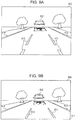
- FIGs. 9A and 9B are first diagrams illustrating a concrete example of the display image data generated by the display control apparatus 120 according to the first embodiment.
- the image data 400 transmitted from the imaging apparatus 110 is displayed as a comparison.
- Fig. 9B display image data 900 generated by the display control apparatus 120 based on the image data 400 of Fig. 9A is illustrated.
- the display control apparatus 120 may convert the image size of the image data 400 into a size suitable for display. Furthermore, according to the display image data 900 of Fig. 9B , the display control apparatus 120 avoids bending of the image elements 411 and 412 indicating the traffic lane lines and the image elements 413 and 414 indicating the step surfaces between the road and the sideways.
- Figs. 10A and 10B are second diagrams illustrating a concrete example of the display image data generated by the display control apparatus 120 according to the first embodiment. Note that Figs. 10A and 10B are different from Figs. 9A and 9B in image data to be used for generation of the display image data. As illustrated in Fig. 10A , image data 1000 includes an image element 1001 indicating a road surface sign between the image elements 411 and 412 indicating the traffic lane lines.
- the compression region to be compressed by the display control apparatus 120 is positioned only in a center of the image data 1000, and therefore, even if a boundary between the compression region and a non-compression region is discontinuous, influence thereof may be small or negligible. Therefore, the image element 1001 indicating the road surface sign does not bend (or does not bend to a degree in which at least the driver visually recognizes the bend).
- the display control apparatus 120 of this embodiment performs the following process.
- the display control apparatus 120 may reduce the feeling of strangeness caused by the display image data visually recognized through the electronic mirror.
- the position coordinates of the pixel region to be extracted as a compression region are determined in advance in accordance with a position where the imaging apparatus is disposed so that image elements indicating traffic lane lines are not incorporated.
- image elements indicating traffic lane lines are detected in image data and position coordinates of a pixel region to be extracted as a compression region are determined based on the detected image elements.
- portions of the second embodiment different from those of the first embodiment will be mainly described.
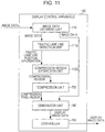
- Fig. 11 is a diagram illustrating an example of the functional configuration of the display control apparatus according to the second embodiment.
- the functional configuration of the display control apparatus of the second embodiment is different from that of the first embodiment illustrated in Fig. 7 in that the display control apparatus of the second embodiment additionally includes a traffic lane line detection unit 1110 and a compression region extraction unit 1120.
- Figs. 12A and 12B are first diagrams illustrating concrete examples of the traffic lane line detection process and the compression region extraction process.
- a state in which the compression region extraction unit 1120 determines the position coordinates for specifying a pixel region 1210 to be extracted as a compression region based on the traffic lane line position information transmitted from the traffic lane line detection unit 1110 is illustrated.
- the compression region extraction unit 1120 determines position coordinates of four apices for specifying the pixel region 1210 in accordance with the following process, for example.
- the compression region extraction unit 1120 extracts the pixel region 1210 in the image data 400 which is specified by the determined position coordinates of the four apices (a region sandwiched between the regions 1201 and 1202 in a lower region) as a compression region.
- Figs. 13A and 13B are second diagrams illustrating concrete examples of the traffic lane line detection process and the compression region extraction process.
- a concrete example of the traffic lane line detection process performed by the traffic lane line detection unit 1110 illustrated in Fig. 13A is the same as that in Fig. 12A , and therefore, a description thereof is omitted.
- a state in which the compression region extraction unit 1120 determines position coordinates for specifying pixel regions 1210, 1311, and 1312 to be extracted as compression regions based on traffic lane line position coordinates transmitted from the traffic lane line detection unit 1110 is illustrated.
- the compression region extraction unit 1120 determines position coordinates of four apices for each of the pixel regions 1210, 1311, and 1312 to be specified in accordance with the following process, for example.
- the compression region extraction unit 1120 extracts the pixel region 1311 in the image data 400 which is specified by the determined position coordinates of the four apices as a compression region.
- the compression region extraction unit 1120 extracts the pixel region 1312 in the image data 400 which is specified by the determined position coordinates of the four apices as a compression region.
- the image elements indicating the traffic lane lines do not bend.
- the display control apparatus 120 of this embodiment may reduce the feeling of strangeness caused by display image data visually recognized through an electronic mirror.
- the image elements indicating the traffic lane lines may be detected for each image data, and therefore, the possibility that the image elements indicating the traffic lane lines are incorporated in a compression region may be further reduced.
- Fig. 14B is a diagram illustrating the relationship between the projector 1410 and a projection mirror 1420.
- the projector 1410 is disposed on a ceiling portion in the vehicle.
- display image data emitted from the projector 1410 disposed on the ceiling portion is projected on the projection mirror 1420 disposed in a position of the in-vehicle rearview mirror.
- the driver may visually recognize the display image data through the projection mirror 1420.
- the upper limit position of the pixel region extracted as the compression region is fixed to the first reference position 401 according to the first and second embodiments described above, the upper limit position of the pixel region extracted as the compression region may be variable.
- a following-vehicle detection unit may be disposed to detect a following vehicle in image data and a lower end position of the following vehicle may be set as an upper limit position of a pixel region extracted as a compression region.
- a road surface sign detection unit may be disposed to detect a road surface sign in image data and a lower end position of the road surface sign may be set as an upper limit position of a pixel region to be extracted as a compression region.
- a shape of the pixel region to be extracted as the compression region is trapezoid according to the first and second embodiments described above, the shape of the pixel region to be extracted as the compression region is not limited to trapezoid.
- the traffic lane line detection unit 1110 may estimate traffic lane lines in image data of a current frame based on image data in a frame a predetermined number of frames before the current frame.
- traffic lane line position information transmitted from the traffic lane line detection unit 1110 includes position coordinates based on the image data of the current frame or position coordinates estimated based on the image data in the frame a predetermined number of frames before the current frame.
- a method for compressing a pixel region is not described in the first to third embodiments, an arbitrary method for compressing a pixel region may be employed. For example, predetermined lines in a pixel region to be extracted as a compression region are extracted for compression or an average value of a plurality of pixels arranged adjacent to each other may be calculated in a pixel region to be extracted as a compression region for compression.
- examples of image elements indicating straight objects extending along a vehicle traveling direction include the image elements indicating the traffic lane lines and the image elements indicating the step surfaces between the road and the sideways.
- the image elements indicating the straight objects extending along the vehicle traveling direction are not limited to these.
- the examples of the image elements indicating the straight objects extending along the vehicle traveling direction further include arbitrary image elements, such as image elements indicating guardrails and an image element indicating a center median.
- the embodiments are applicable to display image data visually recognized through an electronic mirror corresponding to a rearview mirror other than the in-vehicle rearview mirror.
- the process of horizontally inverting a captured image may be executed by the display control apparatus 120.
- the display apparatus 130 is disposed in a position of the in-vehicle rearview mirror according to the first embodiment.
- the configuration of the camera monitoring system 100 is not limited to this and a display apparatus including a movable half mirror on a front surface thereof may be disposed in a position of the in-vehicle rearview mirror, for example.
- the display apparatus 130 starts display of display image data when a mode for displaying display image data is turned on, whereas the display apparatus 130 terminates the display of the display image data when the mode is turned off.
- the driver visually recognizes the display image data displayed through the display apparatus 130 so as to check a rear side of the vehicle.
- a mode for functioning the half mirror as an in-vehicle rearview mirror is turned on and the half mirror is moved to a predetermined position.
- the driver checks the rear side of the vehicle through the half mirror.
Landscapes
- Engineering & Computer Science (AREA)
- Multimedia (AREA)
- Mechanical Engineering (AREA)
- Signal Processing (AREA)
- Closed-Circuit Television Systems (AREA)
- Traffic Control Systems (AREA)
- Image Processing (AREA)
- Image Analysis (AREA)
Abstract
Description
- The present invention relates to a display control apparatus, a display control method, and a camera monitoring system.
- In general, a display control technique of functioning a display apparatus or the like as an electronic mirror by installing a camera monitoring system in a vehicle and displaying images obtained by capturing a rear side of the vehicle in the display apparatus or the like in the vehicle has been known.
- In general, when the display apparatus or the like functions as an electronic mirror, a display size thereof is smaller than an image size of the captured image. Therefore, in such a camera monitoring system, a process of converting a size of a captured image into a size suitable for display is performed by deleting portions of a pixel region of the captured image, compressing a pixel region located in a lower portion of the captured image, or the like is performed, for example.
- Here, the pixel region located in the lower portion in the captured image corresponds to a position comparatively close to an own vehicle in a space on the rear side of the vehicle. Therefore, when a configuration in which the pixel region in the lower portion is compressed is employed, a larger region to be particularly checked by a driver may be incorporated in an image obtained after the conversion and a blind region of the driver may be efficiently reduced. The related technique is disclosed in
JP 2013-85142 A - However, when the configuration in which the pixel region in the lower portion is compressed is employed, the driver has a feeling of strangeness when the own vehicle is not followed by another vehicle or when a following vehicle is positioned far away from the own vehicle. In the captured image, if a boundary between a region to be compressed and a region not to be compressed is discontinuous, an object having a straight shape along a vehicle traveling direction, such as a traffic lane line, is seen to be bent in the boundary.
- The present invention is made in view of the foregoing situation and an object of the present invention is to reduce a feeling of strangeness in an image viewed and recognized through the electronic mirror.
- The invention relates to a display control apparatus, method and camera monitoring system according to the appended claims. Embodiments are disclosed in the dependent claims.
- According to an aspect of the present disclosure, a display control apparatus has the following configuration. That is, a display control apparatus configured to be connected to an imaging apparatus installed in a vehicle includes an obtaining unit configured to obtain image data obtained by the imaging apparatus capturing an image of a portion on a rear side of the vehicle, a specifying unit configured to specify, as a compression region, a pixel region which does not include image elements indicating straight objects extending along a traveling direction of the vehicle in a pixel region in a lower portion in the image data, a generation unit configured to generate display image data of a predetermined display size by compressing the specified compression region in the image data, and a controller configured to perform control so that the generated display image data is visually recognized through an electronic mirror disposed as a rearview mirror of the vehicle.
- A feeling of strangeness caused by an image visually recognized through an electronic mirror may be reduced.
-
Fig. 1 is a diagram illustrating an example of a configuration of a camera monitoring system according to a first embodiment; -
Fig. 2 is a diagram illustrating an example of installation of a display apparatus; -
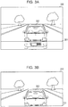
Figs. 3A and 3B are diagrams illustrating the relationship between an image size of image data and a display size of the display apparatus; -
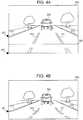
Figs. 4A and 4B are diagrams illustrating a state in which a pixel region in a lower portion of image data is compressed as a compression region and a size of the image data is changed so as to be suitable for the display size; -
Figs. 5A and 5B are diagrams schematically illustrating a method for generating display image data according to the first embodiment; -
Fig. 6 is a diagram illustrating an example of a hardware configuration of a display control apparatus; -
Fig. 7 is a diagram illustrating an example of a functional configuration of the display control apparatus according to the first embodiment; -
Fig. 8 is a flowchart of a flow of a display control process; -
Figs. 9A and 9B are first diagrams illustrating a concrete example of the display image data generated by the display control apparatus according to the first embodiment; -
Figs. 10A and 10B are second diagrams illustrating a concrete example of the display image data generated by the display control apparatus according to the first embodiment; -
Fig. 11 is a diagram illustrating an example of a functional configuration of the display control apparatus according to a second embodiment; -
Figs. 12A and 12B are first diagrams illustrating concrete examples of a traffic lane line detection process and a compression region extraction process; -
Figs. 13A and 13B are second diagrams illustrating concrete examples of the traffic lane line detection process and the compression region extraction process; and -
Figs. 14A and 14B are diagrams illustrating an example of a configuration of a camera monitoring system according to a third embodiment. - Hereinafter, embodiments will be described with reference to the accompanying drawings. Note that components having substantially the same functional configuration are denoted by the same reference numeral, and therefore, a redundant description thereof is omitted.
- First, a configuration of a camera monitoring system installed in a vehicle will be described.
Fig. 1 is a diagram illustrating an example of a configuration of a camera monitoring system according to a first embodiment. As illustrated inFig. 1 , acamera monitoring system 100 includes animaging apparatus 110, adisplay control apparatus 120, and adisplay apparatus 130. Note that, in this embodiment, thecamera monitoring system 100 is activated when an ignition switch of the vehicle is turned on and stops when the ignition switch is turned off. However, thecamera monitoring system 100 may be activated or stop in response to an instruction issued by a driver of the vehicle. - The
imaging apparatus 110 captures images of a rear side of the vehicle. Theimaging apparatus 110 transmits image data obtained by inverting the captured image in a horizontal direction to thedisplay control apparatus 120. Thedisplay control apparatus 120 specifies a compression region, in the image data, to be converted (compressed) to have an image size suitable for a display size of thedisplay apparatus 130 in the pixel region in a lower portion in the image data supplied from theimaging apparatus 110. Note that the compression region is specified such that the driver does not have a feeling of strangeness when generated display image data is displayed in the display apparatus 130 (a detailed description will be made hereinafter). Thedisplay control apparatus 120 extracts the specified compression region from the image data and compresses the extracted compression region so as to generate a compression pixel region which is a portion of the display image data. - The
display control apparatus 120 specifies a deletion region including image data to be converted (deleted) into an image size suitable for a display size of thedisplay apparatus 130 in the lower portion of the image data supplied from theimaging apparatus 110. Thedisplay control apparatus 120 deletes the specified deletion region. Thedisplay control apparatus 120 incorporates the compression pixel region in the image data which has been subjected to the deletion so as to generate display image data. Thedisplay control apparatus 120 transmits the generated display image data to thedisplay apparatus 130. - The
display apparatus 130 is an example of an output apparatus and is constituted by a liquid crystal display apparatus in this embodiment. Thedisplay apparatus 130 displays the display image data supplied from thedisplay control apparatus 120. - An example of installation of the
display apparatus 130 will now be described.Fig. 2 is a diagram illustrating an example of the installation of thedisplay apparatus 130. As illustrated inFig. 2 , thedisplay apparatus 130 is disposed in a position of an in-vehicle rearview mirror in the vehicle (a center position in a front window on a near side) and functions as an electronic mirror which is a substitute of the in-vehicle rearview mirror. - Next, the relationship between an image size of the image data transmitted from the
imaging apparatus 110 and the display size of thedisplay apparatus 130 will be described.Figs. 3A and 3B are diagrams illustrating the relationship between the image size of the image data and the display size of thedisplay apparatus 130. - Specifically,
Fig. 3A is a diagram illustrating an image size ofimage data 300. A horizontal line overlapping theimage data 300 inFig. 3A indicates alower limit position 301 of the display size of thedisplay apparatus 130. - It is assumed here that a process of converting the image size of the
image data 300 into a size suitable for the display size by deleting a pixel region on a lower side of thelower limit position 301 of the display size in theimage data 300 is performed. In this case, the image data subjected to the deletion is illustrated inFig. 3B . As illustrated inFig. 3B , in a case ofimage data 310 obtained by deleting the pixel region on the lower side of thelower limit position 301 so as to be suitable for the display size of thedisplay apparatus 130, a region corresponding to a position comparatively close to the own vehicle in a space on the rear side of the vehicle may not be displayed in thedisplay apparatus 130. - Therefore, in general camera monitoring systems, the process of converting a size of image data into a size suitable for a display size of is performed by compressing a pixel region in a predetermined lower portion in the
image data 300 as a compression region. -
Figs. 4A and 4B are diagrams illustrating a state in which a pixel region in a lower portion of image data is compressed as a compression region and a size of the image data is converted into a display size. InFig. 4A , afirst reference position 401 inimage data 400 indicates an upper limit position of the lower pixel region (the compression region) subjected to the compression. Furthermore, asecond reference position 402 in theimage data 400 indicates a lower limit position of the lower pixel region (the compression region) subjected to the compression. - Note that, in a case where a following vehicle is positioned far away from the own vehicle as illustrated in
Fig. 4A , theimage data 400 includes a large number of image elements indicating straight objects extending along (substantially in parallel to) a vehicle traveling direction. For example, theimage data 400 includesimage elements image elements -
Fig. 4B is a diagram illustrating an example of display image data generated by compressing the lower pixel region defined by the first andsecond reference positions image data 400. As illustrated inFig. 4B , in generateddisplay image data 420, a boundary between the compression region and a non-compression region is discontinuous, and therefore, theimage elements image elements display image data 420 is visually recognized through thedisplay apparatus 130, the driver of the vehicle has a feeling of strangeness. - Accordingly, the
display control apparatus 120 specifies a compression region so that theimage elements image elements display control apparatus 120 specifies only a portion of the lower pixel region in theimage data 400 as the compression region to be compressed. By this, thedisplay control apparatus 120 may reduce the feeling of strangeness of the driver of the vehicle when generated display image data is visually recognized through thedisplay apparatus 130. Hereinafter, thedisplay control apparatus 120 will be described in detail. - First, a method for generating display image data according to the first embodiment will be briefly described.
Figs. 5A and 5B are diagrams schematically illustrating a method for generating display image data according to the first embodiment. - In
Fig. 5A , apixel region 510 in theimage data 400 indicates a compression region. Thepixel region 510 is a portion of the lower pixel region (the general compression region) defined by thefirst reference position 401 and thesecond reference position 402. Specifically, thepixel region 510 is specified so as not to incorporate theimage elements - As illustrated in
Fig. 5A , thepixel region 510 is specified by position coordinates (x1, y1) to (x4, y4) of four apices in theimage data 400. The position coordinates (x1, y1) to (x4, y4) of the four apices in theimage data 400 are determined in advance in accordance with a position where theimaging apparatus 110 is disposed. Specifically, the position coordinates (x1, y1) to (x4, y4) of the four apices are determined as positions which do not include theimage elements - Furthermore, in
Fig. 5A ,deletion regions image data 400 which are to be deleted when display image data is generated. In theimage data 400, thedeletion regions image data 400 and a size of the display image data and are other than thepixel region 510 in a region on a lower side of thelower limit position 301. -
Fig. 5B is a diagram illustrating a state in which thepixel region 510 is compressed and thedeletion regions image data 400. As illustrated inFig. 5B , when thepixel region 510 is compressed, acompression pixel region 530 is generated. Furthermore, when thedeletion regions image data 400 may be converted into the display size. - Furthermore, as illustrated in
Fig. 5B , theimage elements image data 400, and therefore, theimage elements - Furthermore, since the region positioned comparatively in the vicinity of the own vehicle in the space on the rear side of the vehicle is compressed (refer to the compression pixel region 530) as illustrated in
Fig. 5B , a large region which is desired by the driver of the vehicle to be checked may be incorporated in an image obtained after the conversion. - Next, a hardware configuration of the
display control apparatus 120 will be described.Fig. 6 is a diagram illustrating an example of a hardware configuration of thedisplay control apparatus 120. Thedisplay control apparatus 120 includes a central processing unit (CPU) 601, a read only memory (ROM) 602, and a random access memory (RAM) 603 as illustrated inFig. 6 . Thedisplay control apparatus 120 further includes a graphic processing unit (GPU) 604 and an interface (I/F)device 605. Note that the units included in thedisplay control apparatus 120 are connected to one another through abus 606. - The
CPU 601 executes various programs (including a display control program) installed in theROM 602. TheROM 602 which is a nonvolatile memory functions as a main storage device which stores the various programs to be executed by theCPU 601. TheRAM 603 is a volatile memory, such as a dynamic random access memory (DRAM) or a static random access memory (SRAM). TheRAM 603 functions as the main storage device which provides a work area in which the various programs installed in theROM 602 are developed before being executed by theCPU 601. - The
GPU 604 is an integrated circuit dedicated for image processing and performs generation of display image data to be displayed in thedisplay apparatus 130 in response to an instruction issued by theCPU 601 which executes the display control program in this embodiment. The I/F device 605 is a connection device for connecting theimaging apparatus 110 and thedisplay apparatus 130 to thedisplay control apparatus 120. - Next, a functional configuration of the
display control apparatus 120 will be described.Fig. 7 is a diagram illustrating an example of a functional configuration of thedisplay control apparatus 120 according to the first embodiment. As described above, the display control program is installed in thedisplay control apparatus 120. When thecamera monitoring system 100 is activated, thedisplay control apparatus 120 executes the display control program. By this, thedisplay control apparatus 120 functions as an imagedata obtaining unit 710, a compressionregion extraction unit 720, acompression unit 730, ageneration unit 740, and acontroller 750. - The image
data obtaining unit 710 which is an example of an obtaining unit obtains image data transmitted from theimaging apparatus 110. The imagedata obtaining unit 710 transmits the obtained image data to the compressionregion extraction unit 720 and thegeneration unit 740 in a unit of frame. - The compression
region extraction unit 720 which is an example of a specifying unit specifies thepixel region 510 in theimage data 400 using the position coordinates (x1, y1) to (x4, y4) in theimage data 400 which are determined in advance in accordance with the position where theimaging apparatus 110 is disposed. Furthermore, the compressionregion extraction unit 720 extracts the specifiedpixel region 510 as a compression region to be transmitted to thecompression unit 730. - The
compression unit 730 compresses the compression region transmitted from the compressionregion extraction unit 720 so as to generate thecompression pixel region 530. Thecompression unit 730 compresses the compression region so that the lower limit position of the compression region matches thelower limit position 301 of theimage data 400 so as to generate thecompression pixel region 530. Furthermore, thecompression unit 730 transmits the generatedcompression pixel region 530 to thegeneration unit 740. - The
generation unit 740 deletes the region positioned on a lower side relative to thelower limit position 301 of theimage data 400 transmitted from the imagedata obtaining unit 710 before incorporating thecompression pixel region 530 transmitted from thecompression unit 730 into a corresponding position so as to generate display image data. Furthermore, thegeneration unit 740 transmits the generated display image data to thecontroller 750. - The
controller 750 causes thedisplay apparatus 130 to display the display image data transmitted from thegeneration unit 740. By this, the driver of the vehicle may visibly recognize the display image data through thedisplay apparatus 130. - Next, a flow of a display control process executed by the
display control apparatus 120 will be described.Fig. 8 is a flowchart of the flow of the display control process. When thecamera monitoring system 100 is activated, thedisplay control apparatus 120 executes the display control process illustrated inFig. 8 . - In step S801, the image
data obtaining unit 710 obtains image data transmitted from theimaging apparatus 110 and transmits the image data to the compressionregion extraction unit 720 and thegeneration unit 740 on a frame-by-frame basis. - In step S802, the compression
region extraction unit 720 extracts a compression region in the image data and transmits the compression region to thecompression unit 730. In step S803, thecompression unit 730 compresses the compression region transmitted from the compressionregion extraction unit 720 so as to generate a compression pixel region. - In step S804, the
generation unit 740 deletes the region positioned on a lower side relative to thelower limit position 301 of the image data transmitted from the imagedata obtaining unit 710 before incorporating the compression pixel region transmitted from thecompression unit 730 into a corresponding position so as to generate display image data. - In step S805, the
controller 750 transmits the display image data to thedisplay apparatus 130 and causes thedisplay apparatus 130 to display the display image data. In step S806, the imagedata obtaining unit 710 determines whether the display control process is to be terminated. When thecamera monitoring system 100 is not stopped, the imagedata obtaining unit 710 determines that the display control process is not to be terminated in step S806 (No) and the process returns to step S801. - On the other hand, when the
camera monitoring system 100 is stopped, the imagedata obtaining unit 710 determines that the display control process is to be terminated in step S806 (Yes) and the display control process is terminated. - Next, a concrete example of the display image data generated by the
display control apparatus 120 will be described.Figs. 9A and 9B are first diagrams illustrating a concrete example of the display image data generated by thedisplay control apparatus 120 according to the first embodiment. InFig. 9A , theimage data 400 transmitted from theimaging apparatus 110 is displayed as a comparison. InFig. 9B ,display image data 900 generated by thedisplay control apparatus 120 based on theimage data 400 ofFig. 9A is illustrated. - According to the
display image data 900 ofFig. 9B , thedisplay control apparatus 120 may convert the image size of theimage data 400 into a size suitable for display. Furthermore, according to thedisplay image data 900 ofFig. 9B , thedisplay control apparatus 120 avoids bending of theimage elements image elements -
Figs. 10A and 10B are second diagrams illustrating a concrete example of the display image data generated by thedisplay control apparatus 120 according to the first embodiment. Note thatFigs. 10A and 10B are different fromFigs. 9A and 9B in image data to be used for generation of the display image data. As illustrated inFig. 10A ,image data 1000 includes animage element 1001 indicating a road surface sign between theimage elements - Even in this case, the
display control apparatus 120 executes a similar generation process on theimage data 1000 so as to generatedisplay image data 1010. As illustrated in thedisplay image data 1010 ofFig. 10B , theimage element 1001 indicating the road surface sign is compressed in a vertical direction by thedisplay control apparatus 120. Therefore, although a length is reduced when compared with theimage element 1001 before the compression (theimage element 1001 indicating the road surface sign in theimage data 1000 ofFig. 10A ), the entire road surface sign may be incorporated in thedisplay image data 1010 obtained after the conversion. Furthermore, the compression region to be compressed by thedisplay control apparatus 120 is positioned only in a center of theimage data 1000, and therefore, even if a boundary between the compression region and a non-compression region is discontinuous, influence thereof may be small or negligible. Therefore, theimage element 1001 indicating the road surface sign does not bend (or does not bend to a degree in which at least the driver visually recognizes the bend). - As is apparent from the description above, the
display control apparatus 120 of this embodiment performs the following process. - The
display control apparatus 120 determines in advance position coordinates of a pixel region which does not include image elements indicating straight objects extending along a vehicle traveling direction, such as a traffic lane line, in image data obtained by the imaging apparatus capturing an image of a portion on a rear side of a vehicle based on an installation position of the imaging apparatus. - The
display control apparatus 120 compresses the pixel region in the image data specified based on the determined positional coordinates as a compression region so as to generate a compression pixel region. - The
display control apparatus 120 generates display image data by incorporating the generated compression pixel region in a position corresponding to the image data in which a region on a lower side relative to the lower limit position of the display size is deleted. - Accordingly, in the display image data generated by the
display control apparatus 120, the image elements indicating straight objects extending along the vehicle traveling direction, such as a traffic lane line, do not bend. Specifically, thedisplay control apparatus 120 of this embodiment may reduce the feeling of strangeness caused by the display image data visually recognized through the electronic mirror. - According to the first embodiment described above, the position coordinates of the pixel region to be extracted as a compression region are determined in advance in accordance with a position where the imaging apparatus is disposed so that image elements indicating traffic lane lines are not incorporated.
- On the other hand, according to a second embodiment, image elements indicating traffic lane lines are detected in image data and position coordinates of a pixel region to be extracted as a compression region are determined based on the detected image elements. Hereinafter, portions of the second embodiment different from those of the first embodiment will be mainly described.
- First, a functional configuration of a display control apparatus according to the second embodiment will be described.
Fig. 11 is a diagram illustrating an example of the functional configuration of the display control apparatus according to the second embodiment. The functional configuration of the display control apparatus of the second embodiment is different from that of the first embodiment illustrated inFig. 7 in that the display control apparatus of the second embodiment additionally includes a traffic laneline detection unit 1110 and a compressionregion extraction unit 1120. - The traffic lane
line detection unit 1110 detects image elements indicating traffic lane lines in image data transmitted from an imagedata obtaining unit 710. The traffic laneline detection unit 1110 transmits position coordinates indicating positions of the detected image elements indicating the traffic lane lines in the image data to the compressionregion extraction unit 1120 as traffic lane line position information. - The compression
region extraction unit 1120 determines position coordinates for specifying a pixel region to be extracted as a compression region based on the traffic lane line position information transmitted from the traffic laneline detection unit 1110. Specifically, the compressionregion extraction unit 1120 determines the position coordinates of the pixel region to be extracted as a compression region such that a region specified based on the traffic lane line position information in a lower pixel region in the image data is not incorporated in the compression region. Furthermore, the compressionregion extraction unit 1120 extracts the pixel region specified based on the determined position coordinates. Furthermore, the compressionregion extraction unit 1120 transmits the extracted pixel region to acompression unit 730 as a compression region. - Next, a traffic lane line detection process performed by the traffic lane
line detection unit 1110 and a compression region extraction process performed by the compressionregion extraction unit 1120 will be described in detail.Figs. 12A and 12B are first diagrams illustrating concrete examples of the traffic lane line detection process and the compression region extraction process. - As illustrated in
Fig. 12A , the traffic laneline detection unit 1110 detectsimage elements image data 400. Furthermore, the traffic laneline detection unit 1110 specifies aregion 1201 including theimage element 411 indicating the traffic lane line and aregion 1202 including theimage element 412 indicating the traffic lane line. Furthermore, the traffic laneline detection unit 1110 transmits traffic lane line position information indicating position coordinates of theregion 1201 in theimage data 400 and traffic lane line position information indicating position coordinates of theregion 1202 in theimage data 400 to the compressionregion extraction unit 1120. - In
Fig. 12B , a state in which the compressionregion extraction unit 1120 determines the position coordinates for specifying apixel region 1210 to be extracted as a compression region based on the traffic lane line position information transmitted from the traffic laneline detection unit 1110 is illustrated. As illustrated inFig. 12B , the compressionregion extraction unit 1120 determines position coordinates of four apices for specifying thepixel region 1210 in accordance with the following process, for example. - A point positioned on a
first reference position 401 and separated from theregion 1201 leftward by a distance L1 is determined as a position coordinate (x1, y1) of an upper right apex of thepixel region 1210. - A point positioned on a
second reference position 402 and separated from theregion 1201 leftward by a distance L2 is determined as a position coordinate (x2, y2) of a lower right apex of thepixel region 1210. - A point positioned on the
first reference position 401 and separated from theregion 1202 rightward by a distance L3 is determined as a position coordinate (x3, y3) of an upper left apex of thepixel region 1210. - A point positioned on the
second reference position 402 and separated from theregion 1202 rightward by a distance L4 is determined as a position coordinate (x4, y4) of a lower left apex of thepixel region 1210. - The compression
region extraction unit 1120 extracts thepixel region 1210 in theimage data 400 which is specified by the determined position coordinates of the four apices (a region sandwiched between theregions -
Figs. 13A and 13B are second diagrams illustrating concrete examples of the traffic lane line detection process and the compression region extraction process. A concrete example of the traffic lane line detection process performed by the traffic laneline detection unit 1110 illustrated inFig. 13A is the same as that inFig. 12A , and therefore, a description thereof is omitted. - In
Fig. 13B , a state in which the compressionregion extraction unit 1120 determines position coordinates for specifyingpixel regions line detection unit 1110 is illustrated. As illustrated inFig. 13B , the compressionregion extraction unit 1120 determines position coordinates of four apices for each of thepixel regions -
- Determination of the position coordinates of the
pixel region 1210 has been described with reference toFig. 12B , and therefore, the description thereof is omitted here. -
- A point positioned on the
first reference position 401 and separated from theregion 1201 rightward by a distance L5 is determined as a position coordinate (x5, y5) of an upper left apex of thepixel region 1311. - A point positioned on the
first reference position 401 and separated from the upper left apex of theregion 1311 rightward by a distance L6 is determined as a position coordinate (x6, y6) of an upper right apex of thepixel region 1311. - A point positioned on the
second reference position 402 and separated from theregion 1201 rightward by a distance L7 is determined as a position coordinate (x7, y7) of a lower left apex of thepixel region 1311. - A point positioned on the
second reference position 402 and separated from the lower left apex of theregion 1311 rightward by a distance L8 is determined as a position coordinate (x8, y8) of a lower right apex of thepixel region 1311. - The compression
region extraction unit 1120 extracts thepixel region 1311 in theimage data 400 which is specified by the determined position coordinates of the four apices as a compression region. -
- A point positioned on the
first reference position 401 and separated from theregion 1202 leftward by a distance L9 is determined as a position coordinate (x9, y9) of an upper right apex of thepixel region 1312. - A point positioned on the
first reference position 401 and separated from the upper right apex of theregion 1312 leftward by a distance L10 is determined as a position coordinate (x10, y10) of an upper left apex of thepixel region 1312. - A point positioned on the
second reference position 402 and separated from theregion 1202 leftward by a distance L11 is determined as a position coordinate (x11, y11) of a lower right apex of thepixel region 1312. - A point positioned on the
second reference position 402 and separated from the lower right apex of theregion 1312 leftward by a distance L12 is determined as a position coordinate (x12, y12) of a lower left apex of thepixel region 1312. - The compression
region extraction unit 1120 extracts thepixel region 1312 in theimage data 400 which is specified by the determined position coordinates of the four apices as a compression region. - As is apparent from the foregoing description, the
display control apparatus 120 of this embodiment performs the following process. - In the image data obtained by the imaging apparatus by capturing an image of a portion on a rear side of the vehicle, image elements indicating traffic lane lines are detected and position coordinates of pixel regions which do not include the detected image elements are determined.
- The pixel regions in the image data specified based on the determined positional coordinates are compressed as compression regions so as to generate compression pixel regions.
- Display image data is generated by incorporating the generated compression pixel regions in positions in the image data in which a lower region relative to a lower limit position of a display size is deleted.
- Accordingly, in the display image data generated by the
display control apparatus 120, the image elements indicating the traffic lane lines do not bend. Specifically, thedisplay control apparatus 120 of this embodiment may reduce the feeling of strangeness caused by display image data visually recognized through an electronic mirror. Note that, according to this embodiment, the image elements indicating the traffic lane lines may be detected for each image data, and therefore, the possibility that the image elements indicating the traffic lane lines are incorporated in a compression region may be further reduced. - According to the first and second embodiments described above, the
display apparatus 130 is disposed in a position of an in-vehicle rearview mirror and thedisplay apparatus 130 functions as an electronic mirror in thecamera monitoring system 100. However, a configuration of thecamera monitoring system 100 is not limited to this. For example, a projection mirror may be disposed in the position of the in-vehicle rearview mirror and display image data may be projected on the projection mirror through a projector so that the projection mirror functions as an electronic mirror. -
Figs. 14A and 14B are diagrams illustrating an example of a configuration of acamera monitoring system 1400 according to a third embodiment. Thecamera monitoring system 1400 ofFig. 14A is different from thecamera monitoring system 100 ofFig. 1 in that a projector (an image projection apparatus) 1410 is installed as an output apparatus instead of thedisplay apparatus 130. Note that, in a case of thecamera monitoring system 1400, display image data is projected on the projection mirror and is horizontally inverted in an optical manner by the projection mirror, and therefore, a captured image is not required to be horizontally inverted by animaging apparatus 110. Therefore, the display image data transmitted from adisplay control apparatus 120 to theprojector 1410 is generated based on image data transmitted in a state in which a captured image is not horizontally inverted. -
Fig. 14B is a diagram illustrating the relationship between theprojector 1410 and aprojection mirror 1420. In this embodiment, theprojector 1410 is disposed on a ceiling portion in the vehicle. As illustrated inFig. 14B , display image data emitted from theprojector 1410 disposed on the ceiling portion is projected on theprojection mirror 1420 disposed in a position of the in-vehicle rearview mirror. By this, the driver may visually recognize the display image data through theprojection mirror 1420. - Although the upper limit position of the pixel region extracted as the compression region is fixed to the
first reference position 401 according to the first and second embodiments described above, the upper limit position of the pixel region extracted as the compression region may be variable. Specifically, a following-vehicle detection unit may be disposed to detect a following vehicle in image data and a lower end position of the following vehicle may be set as an upper limit position of a pixel region extracted as a compression region. Alternatively, a road surface sign detection unit may be disposed to detect a road surface sign in image data and a lower end position of the road surface sign may be set as an upper limit position of a pixel region to be extracted as a compression region. Note that, although a shape of the pixel region to be extracted as the compression region is trapezoid according to the first and second embodiments described above, the shape of the pixel region to be extracted as the compression region is not limited to trapezoid. - Furthermore, although a method for detecting the
image elements image elements image elements image elements line detection unit 1110 may estimate traffic lane lines in image data of a current frame based on image data in a frame a predetermined number of frames before the current frame. Specifically, traffic lane line position information transmitted from the traffic laneline detection unit 1110 includes position coordinates based on the image data of the current frame or position coordinates estimated based on the image data in the frame a predetermined number of frames before the current frame. - Although a method for compressing a pixel region is not described in the first to third embodiments, an arbitrary method for compressing a pixel region may be employed. For example, predetermined lines in a pixel region to be extracted as a compression region are extracted for compression or an average value of a plurality of pixels arranged adjacent to each other may be calculated in a pixel region to be extracted as a compression region for compression.
- Furthermore, according to the first to third embodiments, examples of image elements indicating straight objects extending along a vehicle traveling direction include the image elements indicating the traffic lane lines and the image elements indicating the step surfaces between the road and the sideways. However, the image elements indicating the straight objects extending along the vehicle traveling direction are not limited to these. The examples of the image elements indicating the straight objects extending along the vehicle traveling direction further include arbitrary image elements, such as image elements indicating guardrails and an image element indicating a center median.
- Furthermore, although the display image data visually recognized through the electronic mirror corresponding to an in-vehicle rearview mirror is described in the first to third embodiments, the embodiments are applicable to display image data visually recognized through an electronic mirror corresponding to a rearview mirror other than the in-vehicle rearview mirror.
- Furthermore, although the image data obtained by horizontally inverting an image captured by the
imaging apparatus 110 is transmitted to thedisplay control apparatus 120 according to the first and second embodiments, the process of horizontally inverting a captured image may be executed by thedisplay control apparatus 120. - Furthermore, the
display apparatus 130 is disposed in a position of the in-vehicle rearview mirror according to the first embodiment. However, the configuration of thecamera monitoring system 100 is not limited to this and a display apparatus including a movable half mirror on a front surface thereof may be disposed in a position of the in-vehicle rearview mirror, for example. In this case, thedisplay apparatus 130 starts display of display image data when a mode for displaying display image data is turned on, whereas thedisplay apparatus 130 terminates the display of the display image data when the mode is turned off. During the mode is in the On state, the driver visually recognizes the display image data displayed through thedisplay apparatus 130 so as to check a rear side of the vehicle. - On the other hand, when the mode for displaying the display image data is in the Off state, a mode for functioning the half mirror as an in-vehicle rearview mirror is turned on and the half mirror is moved to a predetermined position. In this case, the driver checks the rear side of the vehicle through the half mirror.
- Note that the present disclosure is not limited to the configurations described herein including the configurations in the foregoing embodiments and combinations with other elements. Accordingly, the present invention may be changed without departing from the scope of the present invention and appropriately defined in accordance with an application form.
Claims (9)
- A display control apparatus configured to be connected to an imaging apparatus installed in a vehicle, the display control apparatus comprising:an obtaining unit (710) configured to obtain image data obtained by the imaging apparatus capturing an image of a portion on a rear side of the vehicle;a specifying unit (720, 1120) configured to specify, as a compression region, a pixel region which does not include image elements indicating straight objects extending along a traveling direction of the vehicle in a pixel region in a lower portion in the image data;a generation unit (740) configured to generate display image data of a predetermined display size by compressing the specified compression region in the image data; anda controller (750) configured to perform control so that the generated display image data is visually recognized through an electronic mirror disposed as a rearview mirror of the vehicle.
- The display control apparatus according to Claim 1, wherein the generation unit (740) is configured to delete a region determined in advance based on a difference between a size of the image data and a size of the display image data from the image data and a compression pixel region obtained by compressing the compression region is incorporated in a portion of the image data which has been subjected to the deletion so that the display image data is generated.
- The display control apparatus according to Claim 1 or 2, wherein the specifying unit (720, 1120) is configured to specifiy the compression region using position coordinates determined in advance based on an installation position of the imaging apparatus.
- The display control apparatus according to Claim 3, wherein the specifying unit (720, 1120) is configured to specifiy a pixel region corresponding to a portion in the vicinity of a center position in a width direction of the vehicle as a compression region.
- The display control apparatus according to one of Claims 1-4, wherein the specifying unit (720, 1120) is configured to detect image elements in the image data and to determine position coordinates of the pixel region which does not include the detected image elements so as to specify the compression region.
- The display control apparatus according to Claim 5,
wherein the straight objects extending along the traveling direction of the vehicle indicate traffic lane lines, and
the specifying unit (720, 1120) is configured to specify a pixel region sandwiched between image elements indicating a plurality of traffic lane lines as a compression region. - The display control apparatus according to any one of Claims 1 to 6, wherein an upper limit position of a pixel region in a lower portion in the image data corresponds to a lower end position of an image element indicating a following vehicle or a lower end position of an image element indicating a road surface sign.
- A display control method of a display control apparatus connected to an imaging apparatus installed in a vehicle, the display control method comprising:obtaining image data obtained by the imaging apparatus capturing an image of a portion on a rear side of the vehicle;specifying, as a compression region, a pixel region which does not include image elements indicating straight objects extending along a traveling direction of the vehicle in a pixel region in a lower portion in the image data;generating display image data of a predetermined display size by compressing the specified compression region in the image data; andperforming control so that the generated display image data is visually recognized through an electronic mirror disposed as a rearview mirror of the vehicle.
- A camera monitoring system comprising:an imaging apparatus configured to capture a rear side of a vehicle;a display control apparatus according to one of claims 1-7 configured to process image data obtained by the imaging apparatus; andan output apparatus connected to the display control apparatus.
Applications Claiming Priority (1)
| Application Number | Priority Date | Filing Date | Title |
|---|---|---|---|
| JP2017124635A JP6837931B2 (en) | 2017-06-26 | 2017-06-26 | Display control device, display control method and camera monitoring system |
Publications (2)
| Publication Number | Publication Date |
|---|---|
| EP3421295A1 true EP3421295A1 (en) | 2019-01-02 |
| EP3421295B1 EP3421295B1 (en) | 2021-03-24 |
Family
ID=62909329
Family Applications (1)
| Application Number | Title | Priority Date | Filing Date |
|---|---|---|---|
| EP18179554.3A Active EP3421295B1 (en) | 2017-06-26 | 2018-06-25 | Display control apparatus, display control method, and camera monitoring system |
Country Status (4)
| Country | Link |
|---|---|
| US (1) | US10464490B2 (en) |
| EP (1) | EP3421295B1 (en) |
| JP (1) | JP6837931B2 (en) |
| CN (1) | CN109120888B (en) |
Families Citing this family (4)
| Publication number | Priority date | Publication date | Assignee | Title |
|---|---|---|---|---|
| EP4131944A4 (en) * | 2020-03-27 | 2023-07-26 | JVCKENWOOD Corporation | Display control device, display control method, and program |
| CN112590670A (en) * | 2020-12-07 | 2021-04-02 | 安徽江淮汽车集团股份有限公司 | Three-lane environment display method, device, equipment and storage medium |
| CN116918320A (en) * | 2021-02-18 | 2023-10-20 | 松下知识产权经营株式会社 | Display control device and display control method |
| US12597345B2 (en) | 2024-05-17 | 2026-04-07 | Toyota Motor Engineering & Manufacturing North America, Inc. | Methods, systems, and devices for e-mirror traffic lane identification |
Citations (2)
| Publication number | Priority date | Publication date | Assignee | Title |
|---|---|---|---|---|
| US20070025637A1 (en) * | 2005-08-01 | 2007-02-01 | Vidya Setlur | Retargeting images for small displays |
| JP2013085142A (en) | 2011-10-11 | 2013-05-09 | Honda Motor Co Ltd | Drive support device for vehicle |
Family Cites Families (18)
| Publication number | Priority date | Publication date | Assignee | Title |
|---|---|---|---|---|
| US5670935A (en) * | 1993-02-26 | 1997-09-23 | Donnelly Corporation | Rearview vision system for vehicle including panoramic view |
| JP3084208B2 (en) * | 1995-05-18 | 2000-09-04 | 株式会社日立製作所 | Image processing device |
| JP4318571B2 (en) * | 2004-03-18 | 2009-08-26 | ソニー株式会社 | camera |
| JP4762698B2 (en) * | 2005-11-30 | 2011-08-31 | アルパイン株式会社 | Vehicle peripheral image display device |
| JP5194679B2 (en) * | 2007-09-26 | 2013-05-08 | 日産自動車株式会社 | Vehicle periphery monitoring device and video display method |
| DE102009000550B4 (en) * | 2009-02-02 | 2018-10-04 | Ford Global Technologies, Llc | Wide-angle imaging system for providing an image of the surroundings of a vehicle, in particular of a motor vehicle |
| JP4914458B2 (en) * | 2009-02-12 | 2012-04-11 | 株式会社日本自動車部品総合研究所 | Vehicle periphery display device |
| JP5619873B2 (en) * | 2010-03-26 | 2014-11-05 | 本田技研工業株式会社 | Device for supporting driving of a vehicle |
| JP2012222664A (en) * | 2011-04-11 | 2012-11-12 | Honda Elesys Co Ltd | On-vehicle camera system |
| CN103609101A (en) * | 2011-06-16 | 2014-02-26 | 爱信精机株式会社 | Vehicle periphery monitoring device |
| JP5741321B2 (en) * | 2011-08-23 | 2015-07-01 | 株式会社富士通ゼネラル | Driving assistance device |
| JP5811804B2 (en) * | 2011-11-24 | 2015-11-11 | トヨタ自動車株式会社 | Vehicle periphery monitoring device |
| JP6081247B2 (en) * | 2013-03-19 | 2017-02-15 | アルパイン株式会社 | Display switching device and display switching method for vehicle rear image |
| JP6142784B2 (en) * | 2013-11-27 | 2017-06-07 | 株式会社デンソー | Driving assistance device |
| WO2016024444A1 (en) * | 2014-08-12 | 2016-02-18 | ソニー株式会社 | Signal processing device, signal processing method and monitoring system |
| KR101646340B1 (en) * | 2014-08-27 | 2016-08-05 | 현대자동차주식회사 | Apparatus and method for displaying vehicle information |
| US10032249B2 (en) * | 2014-09-05 | 2018-07-24 | Sakai Display Products Corporation | Image generating apparatus, image generating method, and computer program |
| JP2018043643A (en) * | 2016-09-14 | 2018-03-22 | 株式会社東海理化電機製作所 | Vehicular visual confirmation device |
-
2017
- 2017-06-26 JP JP2017124635A patent/JP6837931B2/en active Active
-
2018
- 2018-05-17 US US15/982,179 patent/US10464490B2/en active Active
- 2018-05-23 CN CN201810498254.9A patent/CN109120888B/en active Active
- 2018-06-25 EP EP18179554.3A patent/EP3421295B1/en active Active
Patent Citations (2)
| Publication number | Priority date | Publication date | Assignee | Title |
|---|---|---|---|---|
| US20070025637A1 (en) * | 2005-08-01 | 2007-02-01 | Vidya Setlur | Retargeting images for small displays |
| JP2013085142A (en) | 2011-10-11 | 2013-05-09 | Honda Motor Co Ltd | Drive support device for vehicle |
Also Published As
| Publication number | Publication date |
|---|---|
| JP6837931B2 (en) | 2021-03-03 |
| US10464490B2 (en) | 2019-11-05 |
| CN109120888B (en) | 2021-05-18 |
| US20180370439A1 (en) | 2018-12-27 |
| CN109120888A (en) | 2019-01-01 |
| JP2019006282A (en) | 2019-01-17 |
| EP3421295B1 (en) | 2021-03-24 |
Similar Documents
| Publication | Publication Date | Title |
|---|---|---|
| EP3421295B1 (en) | Display control apparatus, display control method, and camera monitoring system | |
| KR101362324B1 (en) | System and Method for Lane Departure Warning | |
| CN100490530C (en) | Blind spot image display apparatus and method thereof for vehicle | |
| JP4544028B2 (en) | In-vehicle image processing apparatus and image processing method | |
| US20220166924A1 (en) | Image display apparatus | |
| EP2848475A1 (en) | Overhead view image display device | |
| US9877011B2 (en) | Image display apparatus and image display method | |
| CN109263557B (en) | Vehicle blind area detection method | |
| JP6543050B2 (en) | Obstacle detection device and obstacle detection method | |
| CN105453536A (en) | Image processing device, and image processing method | |
| US20190100144A1 (en) | Bird's-eye view video generation device, bird's-eye view video generation system, bird's-eye view video generation method, and non-transitory storage medium | |
| JP7354773B2 (en) | Object detection device, object detection method, and object detection program | |
| JP2011170568A (en) | Device and method for detecting obstacle | |
| KR101876032B1 (en) | Apparatus and Method for displaying parking zone | |
| JP5245471B2 (en) | Imaging apparatus, and image processing apparatus and method | |
| US20240062389A1 (en) | Monitoring apparatus, monitoring system, monitoring method, and computer-readable storage medium | |
| JP4404047B2 (en) | Obstacle collision determination system, determination apparatus, obstacle collision determination method, and computer program | |
| JP5040985B2 (en) | Alert system | |
| JP4799236B2 (en) | In-vehicle display system | |
| KR101724656B1 (en) | Apparatus and method for extracting obstacle extraction base on difference-image | |
| KR20250015499A (en) | Apparatus and method for recognizing an image of vehicle | |
| JP2019004340A (en) | Display control device, display control method, and camera monitoring system | |
| KR20180116603A (en) | Method of video image calibration for circumstances adaptive and system including the same | |
| JP2005202782A (en) | Image processing apparatus, image processing method, and image processing program |
Legal Events
| Date | Code | Title | Description |
|---|---|---|---|
| PUAI | Public reference made under article 153(3) epc to a published international application that has entered the european phase |
Free format text: ORIGINAL CODE: 0009012 |
|
| STAA | Information on the status of an ep patent application or granted ep patent |
Free format text: STATUS: THE APPLICATION HAS BEEN PUBLISHED |
|
| AK | Designated contracting states |
Kind code of ref document: A1 Designated state(s): AL AT BE BG CH CY CZ DE DK EE ES FI FR GB GR HR HU IE IS IT LI LT LU LV MC MK MT NL NO PL PT RO RS SE SI SK SM TR |
|
| AX | Request for extension of the european patent |
Extension state: BA ME |
|
| STAA | Information on the status of an ep patent application or granted ep patent |
Free format text: STATUS: REQUEST FOR EXAMINATION WAS MADE |
|
| 17P | Request for examination filed |
Effective date: 20190607 |
|
| RBV | Designated contracting states (corrected) |
Designated state(s): AL AT BE BG CH CY CZ DE DK EE ES FI FR GB GR HR HU IE IS IT LI LT LU LV MC MK MT NL NO PL PT RO RS SE SI SK SM TR |
|
| STAA | Information on the status of an ep patent application or granted ep patent |
Free format text: STATUS: EXAMINATION IS IN PROGRESS |
|
| 17Q | First examination report despatched |
Effective date: 20200109 |
|
| GRAP | Despatch of communication of intention to grant a patent |
Free format text: ORIGINAL CODE: EPIDOSNIGR1 |
|
| STAA | Information on the status of an ep patent application or granted ep patent |
Free format text: STATUS: GRANT OF PATENT IS INTENDED |
|
| INTG | Intention to grant announced |
Effective date: 20201014 |
|
| GRAS | Grant fee paid |
Free format text: ORIGINAL CODE: EPIDOSNIGR3 |
|
| GRAA | (expected) grant |
Free format text: ORIGINAL CODE: 0009210 |
|
| STAA | Information on the status of an ep patent application or granted ep patent |
Free format text: STATUS: THE PATENT HAS BEEN GRANTED |
|
| AK | Designated contracting states |
Kind code of ref document: B1 Designated state(s): AL AT BE BG CH CY CZ DE DK EE ES FI FR GB GR HR HU IE IS IT LI LT LU LV MC MK MT NL NO PL PT RO RS SE SI SK SM TR |
|
| REG | Reference to a national code |
Ref country code: GB Ref legal event code: FG4D |
|
| REG | Reference to a national code |
Ref country code: CH Ref legal event code: EP |
|
| REG | Reference to a national code |
Ref country code: IE Ref legal event code: FG4D |
|
| REG | Reference to a national code |
Ref country code: AT Ref legal event code: REF Ref document number: 1374172 Country of ref document: AT Kind code of ref document: T Effective date: 20210415 Ref country code: DE Ref legal event code: R096 Ref document number: 602018014253 Country of ref document: DE |
|
| REG | Reference to a national code |
Ref country code: LT Ref legal event code: MG9D |
|
| PG25 | Lapsed in a contracting state [announced via postgrant information from national office to epo] |
Ref country code: NO Free format text: LAPSE BECAUSE OF FAILURE TO SUBMIT A TRANSLATION OF THE DESCRIPTION OR TO PAY THE FEE WITHIN THE PRESCRIBED TIME-LIMIT Effective date: 20210624 Ref country code: HR Free format text: LAPSE BECAUSE OF FAILURE TO SUBMIT A TRANSLATION OF THE DESCRIPTION OR TO PAY THE FEE WITHIN THE PRESCRIBED TIME-LIMIT Effective date: 20210324 Ref country code: GR Free format text: LAPSE BECAUSE OF FAILURE TO SUBMIT A TRANSLATION OF THE DESCRIPTION OR TO PAY THE FEE WITHIN THE PRESCRIBED TIME-LIMIT Effective date: 20210625 Ref country code: FI Free format text: LAPSE BECAUSE OF FAILURE TO SUBMIT A TRANSLATION OF THE DESCRIPTION OR TO PAY THE FEE WITHIN THE PRESCRIBED TIME-LIMIT Effective date: 20210324 Ref country code: BG Free format text: LAPSE BECAUSE OF FAILURE TO SUBMIT A TRANSLATION OF THE DESCRIPTION OR TO PAY THE FEE WITHIN THE PRESCRIBED TIME-LIMIT Effective date: 20210624 |
|
| PG25 | Lapsed in a contracting state [announced via postgrant information from national office to epo] |
Ref country code: RS Free format text: LAPSE BECAUSE OF FAILURE TO SUBMIT A TRANSLATION OF THE DESCRIPTION OR TO PAY THE FEE WITHIN THE PRESCRIBED TIME-LIMIT Effective date: 20210324 Ref country code: LV Free format text: LAPSE BECAUSE OF FAILURE TO SUBMIT A TRANSLATION OF THE DESCRIPTION OR TO PAY THE FEE WITHIN THE PRESCRIBED TIME-LIMIT Effective date: 20210324 Ref country code: SE Free format text: LAPSE BECAUSE OF FAILURE TO SUBMIT A TRANSLATION OF THE DESCRIPTION OR TO PAY THE FEE WITHIN THE PRESCRIBED TIME-LIMIT Effective date: 20210324 |
|
| REG | Reference to a national code |
Ref country code: NL Ref legal event code: MP Effective date: 20210324 |
|
| REG | Reference to a national code |
Ref country code: AT Ref legal event code: MK05 Ref document number: 1374172 Country of ref document: AT Kind code of ref document: T Effective date: 20210324 |
|
| PG25 | Lapsed in a contracting state [announced via postgrant information from national office to epo] |
Ref country code: NL Free format text: LAPSE BECAUSE OF FAILURE TO SUBMIT A TRANSLATION OF THE DESCRIPTION OR TO PAY THE FEE WITHIN THE PRESCRIBED TIME-LIMIT Effective date: 20210324 |
|
| PG25 | Lapsed in a contracting state [announced via postgrant information from national office to epo] |
Ref country code: SM Free format text: LAPSE BECAUSE OF FAILURE TO SUBMIT A TRANSLATION OF THE DESCRIPTION OR TO PAY THE FEE WITHIN THE PRESCRIBED TIME-LIMIT Effective date: 20210324 Ref country code: AT Free format text: LAPSE BECAUSE OF FAILURE TO SUBMIT A TRANSLATION OF THE DESCRIPTION OR TO PAY THE FEE WITHIN THE PRESCRIBED TIME-LIMIT Effective date: 20210324 Ref country code: LT Free format text: LAPSE BECAUSE OF FAILURE TO SUBMIT A TRANSLATION OF THE DESCRIPTION OR TO PAY THE FEE WITHIN THE PRESCRIBED TIME-LIMIT Effective date: 20210324 Ref country code: EE Free format text: LAPSE BECAUSE OF FAILURE TO SUBMIT A TRANSLATION OF THE DESCRIPTION OR TO PAY THE FEE WITHIN THE PRESCRIBED TIME-LIMIT Effective date: 20210324 Ref country code: CZ Free format text: LAPSE BECAUSE OF FAILURE TO SUBMIT A TRANSLATION OF THE DESCRIPTION OR TO PAY THE FEE WITHIN THE PRESCRIBED TIME-LIMIT Effective date: 20210324 |
|
| PG25 | Lapsed in a contracting state [announced via postgrant information from national office to epo] |
Ref country code: IS Free format text: LAPSE BECAUSE OF FAILURE TO SUBMIT A TRANSLATION OF THE DESCRIPTION OR TO PAY THE FEE WITHIN THE PRESCRIBED TIME-LIMIT Effective date: 20210724 Ref country code: SK Free format text: LAPSE BECAUSE OF FAILURE TO SUBMIT A TRANSLATION OF THE DESCRIPTION OR TO PAY THE FEE WITHIN THE PRESCRIBED TIME-LIMIT Effective date: 20210324 Ref country code: RO Free format text: LAPSE BECAUSE OF FAILURE TO SUBMIT A TRANSLATION OF THE DESCRIPTION OR TO PAY THE FEE WITHIN THE PRESCRIBED TIME-LIMIT Effective date: 20210324 Ref country code: PT Free format text: LAPSE BECAUSE OF FAILURE TO SUBMIT A TRANSLATION OF THE DESCRIPTION OR TO PAY THE FEE WITHIN THE PRESCRIBED TIME-LIMIT Effective date: 20210726 Ref country code: PL Free format text: LAPSE BECAUSE OF FAILURE TO SUBMIT A TRANSLATION OF THE DESCRIPTION OR TO PAY THE FEE WITHIN THE PRESCRIBED TIME-LIMIT Effective date: 20210324 |
|
| REG | Reference to a national code |
Ref country code: DE Ref legal event code: R097 Ref document number: 602018014253 Country of ref document: DE |
|
| PG25 | Lapsed in a contracting state [announced via postgrant information from national office to epo] |
Ref country code: ES Free format text: LAPSE BECAUSE OF FAILURE TO SUBMIT A TRANSLATION OF THE DESCRIPTION OR TO PAY THE FEE WITHIN THE PRESCRIBED TIME-LIMIT Effective date: 20210324 Ref country code: MC Free format text: LAPSE BECAUSE OF FAILURE TO SUBMIT A TRANSLATION OF THE DESCRIPTION OR TO PAY THE FEE WITHIN THE PRESCRIBED TIME-LIMIT Effective date: 20210324 Ref country code: AL Free format text: LAPSE BECAUSE OF FAILURE TO SUBMIT A TRANSLATION OF THE DESCRIPTION OR TO PAY THE FEE WITHIN THE PRESCRIBED TIME-LIMIT Effective date: 20210324 Ref country code: DK Free format text: LAPSE BECAUSE OF FAILURE TO SUBMIT A TRANSLATION OF THE DESCRIPTION OR TO PAY THE FEE WITHIN THE PRESCRIBED TIME-LIMIT Effective date: 20210324 |
|
| REG | Reference to a national code |
Ref country code: CH Ref legal event code: PL |
|
| PLBE | No opposition filed within time limit |
Free format text: ORIGINAL CODE: 0009261 |
|
| STAA | Information on the status of an ep patent application or granted ep patent |
Free format text: STATUS: NO OPPOSITION FILED WITHIN TIME LIMIT |
|
| PG25 | Lapsed in a contracting state [announced via postgrant information from national office to epo] |
Ref country code: SI Free format text: LAPSE BECAUSE OF FAILURE TO SUBMIT A TRANSLATION OF THE DESCRIPTION OR TO PAY THE FEE WITHIN THE PRESCRIBED TIME-LIMIT Effective date: 20210324 |
|
| 26N | No opposition filed |
Effective date: 20220104 |
|
| REG | Reference to a national code |
Ref country code: BE Ref legal event code: MM Effective date: 20210630 |
|
| PG25 | Lapsed in a contracting state [announced via postgrant information from national office to epo] |
Ref country code: LU Free format text: LAPSE BECAUSE OF NON-PAYMENT OF DUE FEES Effective date: 20210625 |
|
| PG25 | Lapsed in a contracting state [announced via postgrant information from national office to epo] |
Ref country code: LI Free format text: LAPSE BECAUSE OF NON-PAYMENT OF DUE FEES Effective date: 20210630 Ref country code: IE Free format text: LAPSE BECAUSE OF NON-PAYMENT OF DUE FEES Effective date: 20210625 Ref country code: CH Free format text: LAPSE BECAUSE OF NON-PAYMENT OF DUE FEES Effective date: 20210630 |
|
| PG25 | Lapsed in a contracting state [announced via postgrant information from national office to epo] |
Ref country code: IS Free format text: LAPSE BECAUSE OF FAILURE TO SUBMIT A TRANSLATION OF THE DESCRIPTION OR TO PAY THE FEE WITHIN THE PRESCRIBED TIME-LIMIT Effective date: 20210724 |
|
| PG25 | Lapsed in a contracting state [announced via postgrant information from national office to epo] |
Ref country code: BE Free format text: LAPSE BECAUSE OF NON-PAYMENT OF DUE FEES Effective date: 20210630 |
|
| PG25 | Lapsed in a contracting state [announced via postgrant information from national office to epo] |
Ref country code: IT Free format text: LAPSE BECAUSE OF FAILURE TO SUBMIT A TRANSLATION OF THE DESCRIPTION OR TO PAY THE FEE WITHIN THE PRESCRIBED TIME-LIMIT Effective date: 20210324 |
|
| PG25 | Lapsed in a contracting state [announced via postgrant information from national office to epo] |
Ref country code: CY Free format text: LAPSE BECAUSE OF FAILURE TO SUBMIT A TRANSLATION OF THE DESCRIPTION OR TO PAY THE FEE WITHIN THE PRESCRIBED TIME-LIMIT Effective date: 20210324 |
|
| PG25 | Lapsed in a contracting state [announced via postgrant information from national office to epo] |
Ref country code: HU Free format text: LAPSE BECAUSE OF FAILURE TO SUBMIT A TRANSLATION OF THE DESCRIPTION OR TO PAY THE FEE WITHIN THE PRESCRIBED TIME-LIMIT; INVALID AB INITIO Effective date: 20180625 |
|
| PG25 | Lapsed in a contracting state [announced via postgrant information from national office to epo] |
Ref country code: MK Free format text: LAPSE BECAUSE OF FAILURE TO SUBMIT A TRANSLATION OF THE DESCRIPTION OR TO PAY THE FEE WITHIN THE PRESCRIBED TIME-LIMIT Effective date: 20210324 |
|
| PG25 | Lapsed in a contracting state [announced via postgrant information from national office to epo] |
Ref country code: MT Free format text: LAPSE BECAUSE OF FAILURE TO SUBMIT A TRANSLATION OF THE DESCRIPTION OR TO PAY THE FEE WITHIN THE PRESCRIBED TIME-LIMIT Effective date: 20210324 |
|
| PGFP | Annual fee paid to national office [announced via postgrant information from national office to epo] |
Ref country code: DE Payment date: 20250618 Year of fee payment: 8 |
|
| PGFP | Annual fee paid to national office [announced via postgrant information from national office to epo] |
Ref country code: GB Payment date: 20250618 Year of fee payment: 8 |
|
| PGFP | Annual fee paid to national office [announced via postgrant information from national office to epo] |
Ref country code: FR Payment date: 20250625 Year of fee payment: 8 |
|
| PG25 | Lapsed in a contracting state [announced via postgrant information from national office to epo] |
Ref country code: TR Free format text: LAPSE BECAUSE OF FAILURE TO SUBMIT A TRANSLATION OF THE DESCRIPTION OR TO PAY THE FEE WITHIN THE PRESCRIBED TIME-LIMIT Effective date: 20210324 |