EP3421197A1 - Razor handle - Google Patents
Razor handle Download PDFInfo
- Publication number
- EP3421197A1 EP3421197A1 EP18180003.8A EP18180003A EP3421197A1 EP 3421197 A1 EP3421197 A1 EP 3421197A1 EP 18180003 A EP18180003 A EP 18180003A EP 3421197 A1 EP3421197 A1 EP 3421197A1
- Authority
- EP
- European Patent Office
- Prior art keywords
- shaving razor
- depression
- razor handle
- depressions
- handle according
- Prior art date
- Legal status (The legal status is an assumption and is not a legal conclusion. Google has not performed a legal analysis and makes no representation as to the accuracy of the status listed.)
- Withdrawn
Links
- 239000000463 material Substances 0.000 claims description 15
- 239000000203 mixture Substances 0.000 claims description 9
- 238000002834 transmittance Methods 0.000 claims description 5
- 239000004793 Polystyrene Substances 0.000 claims description 4
- 239000004926 polymethyl methacrylate Substances 0.000 claims description 4
- 229920002223 polystyrene Polymers 0.000 claims description 4
- 229920003229 poly(methyl methacrylate) Polymers 0.000 claims description 3
- 229920002635 polyurethane Polymers 0.000 claims description 3
- 239000004814 polyurethane Substances 0.000 claims description 3
- 229920000089 Cyclic olefin copolymer Polymers 0.000 claims description 2
- WWNGFHNQODFIEX-UHFFFAOYSA-N buta-1,3-diene;methyl 2-methylprop-2-enoate;styrene Chemical compound C=CC=C.COC(=O)C(C)=C.C=CC1=CC=CC=C1 WWNGFHNQODFIEX-UHFFFAOYSA-N 0.000 claims description 2
- 230000001788 irregular Effects 0.000 claims description 2
- 239000004417 polycarbonate Substances 0.000 claims description 2
- 229920000515 polycarbonate Polymers 0.000 claims description 2
- 230000003746 surface roughness Effects 0.000 claims description 2
- 238000004891 communication Methods 0.000 abstract description 3
- 230000000007 visual effect Effects 0.000 abstract description 3
- 229920002725 thermoplastic elastomer Polymers 0.000 description 10
- 238000000034 method Methods 0.000 description 8
- 229920003171 Poly (ethylene oxide) Polymers 0.000 description 7
- -1 Hytrel) Polymers 0.000 description 5
- 239000003795 chemical substances by application Substances 0.000 description 5
- 238000000576 coating method Methods 0.000 description 5
- 239000011248 coating agent Substances 0.000 description 4
- 229920003023 plastic Polymers 0.000 description 4
- 239000002131 composite material Substances 0.000 description 3
- 238000013461 design Methods 0.000 description 3
- 238000004519 manufacturing process Methods 0.000 description 3
- 238000007655 standard test method Methods 0.000 description 3
- 229920001935 styrene-ethylene-butadiene-styrene Polymers 0.000 description 3
- 229920003169 water-soluble polymer Polymers 0.000 description 3
- 239000002202 Polyethylene glycol Substances 0.000 description 2
- 239000004743 Polypropylene Substances 0.000 description 2
- 239000000853 adhesive Substances 0.000 description 2
- 230000001070 adhesive effect Effects 0.000 description 2
- FACXGONDLDSNOE-UHFFFAOYSA-N buta-1,3-diene;styrene Chemical compound C=CC=C.C=CC1=CC=CC=C1.C=CC1=CC=CC=C1 FACXGONDLDSNOE-UHFFFAOYSA-N 0.000 description 2
- 239000003086 colorant Substances 0.000 description 2
- 238000009826 distribution Methods 0.000 description 2
- 230000002708 enhancing effect Effects 0.000 description 2
- 229920005669 high impact polystyrene Polymers 0.000 description 2
- 239000004797 high-impact polystyrene Substances 0.000 description 2
- 238000002347 injection Methods 0.000 description 2
- 239000007924 injection Substances 0.000 description 2
- 239000002184 metal Substances 0.000 description 2
- 229910052751 metal Inorganic materials 0.000 description 2
- 229920000728 polyester Polymers 0.000 description 2
- 229920001223 polyethylene glycol Polymers 0.000 description 2
- 229920001155 polypropylene Polymers 0.000 description 2
- 229920000468 styrene butadiene styrene block copolymer Polymers 0.000 description 2
- 239000000126 substance Substances 0.000 description 2
- 229920003176 water-insoluble polymer Polymers 0.000 description 2
- 238000003466 welding Methods 0.000 description 2
- 238000010146 3D printing Methods 0.000 description 1
- 101710141544 Allatotropin-related peptide Proteins 0.000 description 1
- BJRMDQLATQGMCQ-UHFFFAOYSA-N C=C.C=CC=C.C=CC1=CC=CC=C1.C=CC1=CC=CC=C1 Chemical compound C=C.C=CC=C.C=CC1=CC=CC=C1.C=CC1=CC=CC=C1 BJRMDQLATQGMCQ-UHFFFAOYSA-N 0.000 description 1
- 244000043261 Hevea brasiliensis Species 0.000 description 1
- 229920002153 Hydroxypropyl cellulose Polymers 0.000 description 1
- 229920002633 Kraton (polymer) Polymers 0.000 description 1
- 239000004909 Moisturizer Substances 0.000 description 1
- 229920000459 Nitrile rubber Polymers 0.000 description 1
- 229930182556 Polyacetal Natural products 0.000 description 1
- 239000004952 Polyamide Substances 0.000 description 1
- 229920002614 Polyether block amide Polymers 0.000 description 1
- 239000004698 Polyethylene Substances 0.000 description 1
- XECAHXYUAAWDEL-UHFFFAOYSA-N acrylonitrile butadiene styrene Chemical compound C=CC=C.C=CC#N.C=CC1=CC=CC=C1 XECAHXYUAAWDEL-UHFFFAOYSA-N 0.000 description 1
- 229920000122 acrylonitrile butadiene styrene Polymers 0.000 description 1
- 239000004676 acrylonitrile butadiene styrene Substances 0.000 description 1
- 239000000654 additive Substances 0.000 description 1
- 230000000996 additive effect Effects 0.000 description 1
- 229910052782 aluminium Inorganic materials 0.000 description 1
- XAGFODPZIPBFFR-UHFFFAOYSA-N aluminium Chemical compound [Al] XAGFODPZIPBFFR-UHFFFAOYSA-N 0.000 description 1
- 239000003963 antioxidant agent Substances 0.000 description 1
- 239000003212 astringent agent Substances 0.000 description 1
- 238000010560 atom transfer radical polymerization reaction Methods 0.000 description 1
- 229920005549 butyl rubber Polymers 0.000 description 1
- 238000006243 chemical reaction Methods 0.000 description 1
- 239000000701 coagulant Substances 0.000 description 1
- 230000003750 conditioning effect Effects 0.000 description 1
- 239000002826 coolant Substances 0.000 description 1
- 229920001577 copolymer Polymers 0.000 description 1
- 238000005260 corrosion Methods 0.000 description 1
- 230000007797 corrosion Effects 0.000 description 1
- 230000002951 depilatory effect Effects 0.000 description 1
- 229920001971 elastomer Polymers 0.000 description 1
- 239000005038 ethylene vinyl acetate Substances 0.000 description 1
- 230000002209 hydrophobic effect Effects 0.000 description 1
- 229920001600 hydrophobic polymer Polymers 0.000 description 1
- 239000001863 hydroxypropyl cellulose Substances 0.000 description 1
- 235000010977 hydroxypropyl cellulose Nutrition 0.000 description 1
- MTNDZQHUAFNZQY-UHFFFAOYSA-N imidazoline Chemical compound C1CN=CN1 MTNDZQHUAFNZQY-UHFFFAOYSA-N 0.000 description 1
- 238000001746 injection moulding Methods 0.000 description 1
- 238000003780 insertion Methods 0.000 description 1
- 230000037431 insertion Effects 0.000 description 1
- 239000012633 leachable Substances 0.000 description 1
- 239000007788 liquid Substances 0.000 description 1
- 230000001050 lubricating effect Effects 0.000 description 1
- 238000005461 lubrication Methods 0.000 description 1
- 238000003754 machining Methods 0.000 description 1
- 230000000873 masking effect Effects 0.000 description 1
- 239000002855 microbicide agent Substances 0.000 description 1
- 230000001333 moisturizer Effects 0.000 description 1
- 238000000465 moulding Methods 0.000 description 1
- 229920003052 natural elastomer Polymers 0.000 description 1
- 229920001194 natural rubber Polymers 0.000 description 1
- 230000003287 optical effect Effects 0.000 description 1
- 238000004375 physisorption Methods 0.000 description 1
- 239000004033 plastic Substances 0.000 description 1
- 238000005498 polishing Methods 0.000 description 1
- 229920001200 poly(ethylene-vinyl acetate) Polymers 0.000 description 1
- 229920002401 polyacrylamide Polymers 0.000 description 1
- 229920002647 polyamide Polymers 0.000 description 1
- 229920000573 polyethylene Polymers 0.000 description 1
- 229920002338 polyhydroxyethylmethacrylate Polymers 0.000 description 1
- 229920000098 polyolefin Polymers 0.000 description 1
- 229920006324 polyoxymethylene Polymers 0.000 description 1
- 229920001296 polysiloxane Polymers 0.000 description 1
- 229920000036 polyvinylpyrrolidone Polymers 0.000 description 1
- 239000001267 polyvinylpyrrolidone Substances 0.000 description 1
- 235000013855 polyvinylpyrrolidone Nutrition 0.000 description 1
- 239000003755 preservative agent Substances 0.000 description 1
- 230000002265 prevention Effects 0.000 description 1
- 238000007639 printing Methods 0.000 description 1
- 239000005060 rubber Substances 0.000 description 1
- 230000037067 skin hydration Effects 0.000 description 1
- 239000000344 soap Substances 0.000 description 1
- 239000007787 solid Substances 0.000 description 1
- 229920003048 styrene butadiene rubber Polymers 0.000 description 1
- 238000010998 test method Methods 0.000 description 1
- 229920002554 vinyl polymer Polymers 0.000 description 1
- 238000011179 visual inspection Methods 0.000 description 1
- XLYOFNOQVPJJNP-UHFFFAOYSA-N water Substances O XLYOFNOQVPJJNP-UHFFFAOYSA-N 0.000 description 1
- 238000010618 wire wrap Methods 0.000 description 1
Images




Classifications
-
- B—PERFORMING OPERATIONS; TRANSPORTING
- B26—HAND CUTTING TOOLS; CUTTING; SEVERING
- B26B—HAND-HELD CUTTING TOOLS NOT OTHERWISE PROVIDED FOR
- B26B21/00—Razors of the open or knife type; Safety razors or other shaving implements of the planing type; Hair-trimming devices involving a razor-blade; Equipment therefor
- B26B21/40—Details or accessories
- B26B21/52—Handles, e.g. tiltable, flexible
- B26B21/522—Ergonomic details, e.g. shape, ribs or rubber parts
Definitions
- the invention relates to the provision of a handle for a razor which provides both ergonomic handling, improved grip and visual communication cues to the consumer.
- a shaving razor handle (1) having a first portion (12) and a second portion (13) and a silhouette line (14) wherein said first (12) and second (13) portions are joined to one another at said silhouette line (14), wherein said handle (1) is substantially transparent and wherein each of said first (12) and second (13) portions comprises at least one depression (15).
- the handle (1) for a shaving razor comprises an elongated body (2) extending in a longitudinal direction (L) that extends between a proximal end (3) and a terminal end (4) of the handle (1).
- the handle (1) typically comprises a connecting means (5) to connect the handle (1) at the proximal end (3) to a hair removal head, or cartridge (5), described hereinafter.
- the connecting means (5) may connect the handle (1) to the hair removal head (5) such as a cartridge permanently or releasably to enable replacement with another hair removal head.
- the handle (1) may be provided in any shape or form, but is ergonomic to allow easy handling by the user.
- the handle (1) may be generally symmetrical or asymmetrical, and is preferably symmetrical in form about a given axis.
- the handle (1) is elongated shape and preferably has a curved elongated shape which is preferably ergonomically suited to a user's hand shape.
- the shaving razor handle (1) has a first portion (12) and a second portion (13) and a silhouette line (14) wherein said first (12) and second (13) portions are joined to one another at said silhouette line (14) and the silhouette line (14) separates the first (12) and second (13) portions.
- silhouette line (14) refers to the silhouette line formed on the handle surface when the handle is placed on a horizontal surface with the surface that will contain the blades facing towards the horizontal surface without any additional support.
- a portion of the handle facing the light source When light is shone perpendicularly to the horizontal surface a portion of the handle facing the light source will be lit whereas a portion facing away from the light source will be unlit.
- the closed line which separates the lit from the unlit portions which extends around the entire surface of the handle is referred to as the silhouette line herein.
- Each of said first (12) and second (13) portions independently comprises at least one, preferably at least two depressions (15, 115, 116).
- Said first portion (12) has an internal body (21) and an outer surface (10).
- Said second (13) portion has an internal body (22) and an outer surface (11). The first and second outer surfaces (10, 11) are joined at the silhouette line (14).
- the first portion (12,) independently comprises at least one depression (15, 115) extending from said first outer surface (10) into said first internal body (21).
- the outer surface (10) of the first portion (12) faces in the direction away from the consumer's skin.
- the second portion (13,) independently comprises at least one depression (15, 215) extending from said second outer surface (11) into said second internal body (22).
- the outer surface (11) of the second portion (13) faces in the opposing direction towards the consumer's skin.
- each depression (15, 115) on the first portion (12) is defined by a perimeter (16, 116) on said outer first surface (10) and a boundary (17, 117) in said respective body of said first portion (12).
- At least one depression (15, 115) on the first (10) surface independently forms a perimeter (16, 116) at the point of intersection on the outer surface (10).
- the perimeter (16, 116) defines the intersection points of each depression (15, 115) with the outer surface of the first portion (10).
- At least one depression (15, 115) on the first surface (10) further forms a boundary (17, 117) which defines the interface between the depressions within the handle body (2).
- the boundary (17, 117) extends from the perimeter (16, 116) on the first (10) outer surface of the handle (1) into the body (2) of the handle.
- At least one depression (15, 215) on the second (11) surface independently forms a perimeter (16, 216) at the point of intersection on the outer surface (11).
- the perimeter (16, 216) defines the intersection points of each depression (15, 215) with the outer surface of the second (11) portion.
- At least one depression (15, 215) on the second surface (11) further forms a boundary (17, 217) which defines the interface between the depressions within the handle body (2).
- the boundary (17, 217) extends from the perimeter (16, 216) on the second (11) outer surface of the handle (1) into the body (2) of the handle.
- Each depression perimeter (16, 116, 216) of each respective first and second portion (12, 13) may have any size or shape and may be regular or irregular. Suitable shapes include circles, ovals, stars, V shapes, leaves, cogs, droplets, waves, filigrees and hexagons and combinations thereof.
- depressions (15, 115, 215) extending from the first and second surfaces (10, 11) into the respective body portions thereof of a transparent handle enables an optical illusion to be formed by which the depression appears to be distributed through the internal body of the handle (1) and not just the surface of the handle. Such an illusion creates the appearance of depth which is maintained as the handle is observed from differing viewpoints.
- the transparent handle enables the user to more easily view the skin surface to be shaved.
- each depression boundary (17, 117, 217) in each first and second portion (12, 13) is not in direct contact with the depression boundary (17, 117, 217) of any adjacent depression (15, 115, 215). Adjacent depressions may however share a portion of their respective boundaries, whilst maintaining each depression's individual integrity.
- the boundary (17, 117, 217) may be curved, linear and or angular or a combination thereof.
- each depression perimeter (16, 116, 216) is not in direct contact with the depression perimeter (16) of any adjacent depression (15). Adjacent depressions may however share a portion of their respective perimeters, whilst maintaining each depression's individual integrity.
- each depression perimeter (15, 115, 215) is at least 0.1mm, preferably from 1.0mm to 5mm distance (d p ) apart from any adjacent perimeter (15, 115, 215).
- the distance (d b ) between the boundaries (17, 117, 217) of any adjacent depression (15, 115, 215) is at least 1.0mm.
- the handle may have a total number of depressions of from about 2 to about 200, preferably from about 4 to about 100, more preferably from about 10 to about 100, even more preferably from about 20 to about 100, most preferably from about 60 to about 90.
- the first upper surface comprises from about 10 to about 60 depressions and the second surface comprises from about 20 to about 80 depressions.
- the multiple depressions (15, 115, 215) may independently be positioned randomly or in a pattern on the first and second outer surface (10, 11) of the handle (1). In one embodiment a random distribution of depressions (15, 115, 215) is preferred. Whilst not wishing to be bound by theory, it believed that this reflects distributions observed in nature such as for example for water droplets. In one embodiment, as shown in figure 1a and 1b , the handle may have a defined area which is free of depressions (23).
- Each depression (15, 115, 215) may have any size and shape.
- each depression (15, 115, 215) may independently have a volume i.e. the cavity volume of each depression of from 2mm 3 to 32mm 3 , preferably from 5mm 3 to 20mm 3 .
- the depressions have a size and shape which does not allow the insertion of a finger therein, but enables the user to detect the depression by tactile or visual inspection.
- each depression may independently have a major width of from about 1mm to about 100mm, or from about 1mm to about 35mm, or from about 1mm to 10mm or from about 1mm to about 6mm.
- the major width of each of such circular depression perimeter (16) is independently not greater than about 7mm, preferably not greater than about 6mm and more preferably from about 1mm to about 6mm.
- it is preferred that the major width of any depression is substantially less, preferably less than 80%, more preferably less than 50%, than the major width of the handle.
- the handle comprises at least two sets of depressions, preferably at least three sets of depressions.
- Each set of depressions may comprise at least 2 depressions within the set.
- the depressions in each respective set may have substantially the same size and or shape or a feature common to each depression within the set.
- the first set of depressions comprising from about 1 to about 30 depressions
- said depressions may have perimeters in the shape of circles, ovals and ellipses, and each of said depressions independently may have a major width of about 2mm
- a second set of depressions comprising from about 20 to about 40 depressions each of said depressions independently may have a major width of greater than about 2mm and up to about 3mm
- a third set of depressions comprising from about 20 to about 50 depressions each independently may have a major width from greater than about 3mm to about 5mm or about 6mm.
- each depression perimeter (16, 116, 216) defines a depression surface area (118) on the outer surface of the handle and the total sum of all the depression surface areas is 5% to 70%, preferably from 10% to 50%, more preferably from 15% to 30% of the total surface area of the handle. This area excludes connection and or pivot points on the handle.
- At least one depression, preferably at least 60%, preferably at least 80%, most preferably at least 90% of the depressions comprises a fillet radius or chamfer (19) towards the perimeter of the depression,
- the width or diameter of the fillet radius or chamfer (19) is preferably from about 0.1mm to about 2mm, more preferably from about 0.1mm to about 0.5mm.
- At least one depression boundary (17, 117, 217) of the depression is coloured and transparent.
- the depressions may all be coloured with the same or different colours. Providing colour enables the depressions to be more readily observed by the consumer.
- the body of the handle may also be coloured provided that it retains transparency.
- the shaving razor handle may be provided from any suitable material which is transparent. Suitable materials include polymeric materials preferably selected from polystyrene, polycarbonate, polymethyl methacrylate, methyl methacrylate butadiene styrene, polyurethane, cyclo-olefin polymer and mixtures thereof. A particularly preferred material is polymethyl methacrylate such as Zylar TM available from INEOS Styrosolutions.
- the handle is transparent. Transparency may be determined according to ASTM D1003-13, Standard test method for haze and luminous transmittance of transparent plastics. The material utilised for the handle is tested according to this test method in the absence of depressions.
- the handle may have a transmittance of from 80% to 100%, preferably from 90% to 100% determined according to ASTM D1003-13 Standard test method for haze and luminous transmittance of transparent plastics.
- the handle may also have a haze of 20% or less, preferably of 10% or less as determined according to ASTM D1003-13 Standard test method for haze and luminous transmittance of transparent plastics.
- the selection of the roughness of the handle surface can be used to reinforce a desired tactile and or optical experience by the consumer. This roughness range may be achieved by known methods such as electro polishing. It may be desirable to provide distinct areas of the handle which have different degrees of roughness/polish for example to provide grip for the user.
- At least one depression preferably at least 50% of said depressions (15,115, 215) may be provided with a coating or surface texture.
- the coating or surface texture is provided on the surface area of the boundary extending from the perimeter to the boundary thereof.
- Such coatings or textures may assist in the reduction or prevention of the build-up of residues in the depressions which may be both unhygienic and result in an unsatisfactory skin feel i.e. to avoid soap scum etc. from sticking and may affect the optical illusion.
- hydrophobic or omniphobic surfaces would generally be chosen to provide this benefit. Any suitable route for creating this coating can be considered including chemical bonding (ionic or covalent) or physisorption of suitable moieties.
- the coating technique is chosen to be able to withstand the aggressive conditions that the skin contacting surface may be exposed to during use.
- the handles may be manufactured according to any method known in the art. For example injection moulding, 3D printing or additive layer manufacturing, direct machining or any combination thereof may be suitable. Colour may also be provided to the handle and or depressions by any method known in the art such as for example direct object printing techniques.
- the shaving razor system may include a shaving razor cartridge (6) mounted to a handle (1).
- the shaving razor cartridge (6) may be fixedly or pivotably mounted to the handle (1) depending on the overall desired cost and performance.
- the handle (1) may hold a power source, such as one or more batteries (not shown).
- the shaving razor cartridge (6) may be permanently attached or removably mounted from the handle 1, thus allowing the shaving razor cartridge (6) to be replaced.
- the shaving razor cartridge (6) may have a housing (38) with a guard (40), a cap (32) and one or more blades (34) mounted to the housing (38) between the cap (32) and the guard (40).
- the guard (40) may be toward a front portion of the housing 38 and the cap 32 may be toward a rear portion of the housing 38 (i.e., the guard (40) is in front of the blades (34) and the cap is behind the blades (34)).
- the guard (30) and the cap (32) may define a shaving plane that is tangent to the guard (30) and the cap (32).
- the guard (40) may be a solid or segmented bar that extends generally parallel to the blades (34).
- the guard (40) may comprise a skin-engaging member (36) (e.g., a plurality of fins) in front of the blades (34) for stretching the skin during a shaving stroke.
- the skin-engaging member (36) may be insert injection molded or co-injection molded to the housing (38).
- other known assembly methods may also be used such as adhesives, ultrasonic welding, or mechanical fasteners.
- the skin engaging member (36) may be molded from a softer material (i.e., lower durometer hardness) than the housing (38).
- the skin engaging member (36) may have a Shore A hardness of about 20, 30, or 40 to about 50, 60, or 70.
- the skin engaging member (36) may be made from thermoplastic elastomers (TPEs) or rubbers; examples may include, but are not limited to silicones, natural rubber, butyl rubber, nitrile rubber, styrene butadiene rubber, styrene butadiene styrene (SBS) TPEs, styrene ethylene butadiene styrene (SEBS) TPEs (e.g., Kraton), polyester TPEs (e.g., Hytrel), polyamide TPEs (Pebax), polyurethane TPEs, polyolefin based TPEs, and blends of any of these TPEs (e.g., polyester/SEBS blend).
- TPEs thermoplastic elastomers
- SBS nitrile rubber
- SEBS styrene ethylene butadiene styrene
- SEBS styrene ethylene butadiene styren
- skin engaging member (36) may comprise Kraiburg HTC 1028/96, HTC 8802/37, HTC 8802/34, or HTC 8802/11 (KRAIBURG TPE GmbH & Co. KG of Waldkraiburg, Germany).
- a softer material may enhance skin stretching, as well as provide a more pleasant tactile feel against the skin of the user during shaving.
- a softer material may also aid in masking the less pleasant feel of the harder material of the housing 18 and/or the fins against the skin of the user during shaving.
- the blades (34) may be mounted to the housing (38) and secured by one or more clips (42a and 42b). Other assembly methods known to those skilled in the art may also be used to secure and/or mount the blades (34) to the housing (38) including, but not limited to, wire wrapping, cold forming, hot staking, insert molding, ultrasonic welding, and adhesives.
- the clips (42a and 42b) may comprise a metal, such as aluminum for conducting heat and acting as a sacrificial anode to help prevent corrosion of the blades (34). Although five blades (34) are shown, the housing (38) may have more or fewer blades depending on the desired performance and cost of the shaving razor cartridge (6).
- the cap (32) may be a separate molded (e.g., a shaving aid filled reservoir) or extruded component (e.g., an extruded lubrication strip) that is mounted to the housing (38).
- the cap (32) may be a plastic or metal bar to support the skin and define the shaving plane.
- the cap 32 may be molded or extruded from the same material as the housing (38) or may be molded or extruded from a more lubricious shaving aid composite that has one or more water-leachable shaving aid materials to provide increased comfort during shaving.
- the shaving aid composite may comprise a water-insoluble polymer and a skin-lubricating water-soluble polymer.
- Suitable water-insoluble polymers which may be used include, but are not limited to, polyethylene, polypropylene, polystyrene, butadiene-styrene copolymer (e.g., medium and high impact polystyrene), polyacetal, acrylonitrile-butadiene-styrene copolymer, ethylene vinyl acetate copolymer and blends such as polypropylene/polystyrene blend, may have a high impact polystyrene (i.e., Polystyrene-butadiene), such as Mobil 4324 (Mobil Corporation).
- polystyrene i.e., Polystyrene-butadiene
- Mobil 4324 Mobil Corporation
- Suitable skin lubricating water-soluble polymers may include polyethylene oxide, polyvinyl pyrrolidone, polyacrylamide, hydroxypropyl cellulose, polyvinyl imidazoline, and polyhydroxyethylmethacrylate.
- Other water-soluble polymers may include the polyethylene oxides generally known as POLYOX (available from Union Carbide Corporation) or ALKOX (available from Meisei Chemical Works, Kyota, Japan). These polyethylene oxides may have molecular weights of about 100,000 to 6 million, for example, about 300,000 to 5 million.
- the polyethylene oxide may comprise a blend of about 40 to 80% of polyethylene oxide having an average molecular weight of about 5 million (e.g., POLYOX COAGULANT) and about 60 to 20% of polyethylene oxide having an average molecular weight of about 300,000 (e.g., POLYOX WSR-N-750).
- the polyethylene oxide blend may also contain up to about 10% by weight of a low molecular weight (i.e., MW ⁇ 10,000) polyethylene glycol such as PEG-100.
- the shaving aid composite may also optionally include an inclusion complex of a skin-soothing agent with a cylcodextrin, low molecular weight water-soluble release enhancing agents such as polyethylene glycol (e.g., 1-10% by weight), water-swellable release enhancing agents such as cross-linked polyacrylics (e.g., 2-7% by weight), colorants, antioxidants, preservatives, microbicidal agents, beard softeners, astringents, depilatories, medicinal agents, conditioning agents, moisturizers, cooling agents, etc.
- a skin-soothing agent with a cylcodextrin low molecular weight water-soluble release enhancing agents such as polyethylene glycol (e.g., 1-10% by weight), water-swellable release enhancing agents such as cross-linked polyacrylics (e.g., 2-7% by weight), colorants, antioxidants, preservatives, microbicidal agents, beard softeners, astringents, de
Landscapes
- Life Sciences & Earth Sciences (AREA)
- Forests & Forestry (AREA)
- Engineering & Computer Science (AREA)
- Mechanical Engineering (AREA)
- Cosmetics (AREA)
Abstract
Description
- The invention relates to the provision of a handle for a razor which provides both ergonomic handling, improved grip and visual communication cues to the consumer.
- There is a continuing desire to improve the aesthetic appearance of razor handles whilst ensuring desirable ergonomics, and grip during use. Manufacturers of such products also desire to utilise the aesthetics of the product to communicate and or reinforce benefits of the razor product itself to the consumer and or to provide a visual or tactile cue of the associated benefits of the razor to the consumer. A particular desirable communication area is skin hydration.
- There is also a desire to reduce the amount of materials used in the production of handles whilst not compromising on ergonomics, user grip and the desired weight of the handle and thereby improve the sustainability profile of these consumer products. There is also a need to improve the line of sight by the user of the skin area to be shaved which is obstructed by the razor itself.
- Many commercially available razors have handles that have aesthetically pleasing patterns on the handle surface and or patterns which are hollowed out from the handle to provide aesthetically pleasing designs such as flowers or angular patterns. Such designs are either primarily to improve the aesthetic appeal of the razor and or to reduce the amount of material used for handle manufacture. Such handles are typically opaque and the design can only be viewed from one surface of the handle. Products which are hollowed out are also opaque and are either hollowed out on one or each side or through the entire handle to aid grip and or rinsing performance.
US2013/0061481 describes a razor handle which has a concave recess on at least one side to facilitate secure grasping by the finger of the user. - Nevertheless there is still a need to provide a razor handle which offers both improved grip and ergonomics and reduces the overall amount of material required. There is also a need to visually communicate the performance benefits of the overall razor product to the consumer.
- A shaving razor handle (1) having a first portion (12) and a second portion (13) and a silhouette line (14) wherein said first (12) and second (13) portions are joined to one another at said silhouette line (14), wherein said handle (1) is substantially transparent and wherein each of said first (12) and second (13) portions comprises at least one depression (15).
- While the specification concludes with claims particularly pointing out and distinctly claiming the subject matter that is regarded as the present invention, it is believed that the invention will be more fully understood from the following description taken in conjunction with the accompanying drawings.
-
Figure 1a and 1b are a top and side view respectively of one embodiment of a shaving razor handle together with a cartridge. -
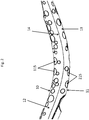
Figure 2 is an enlarged section of the side view offigure 1b . -
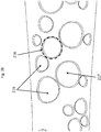
Figure 3a and3b are further enlarged sections of the top view offigure 1a . -
Figure 4 is an enlarged cross section of section offigure 1b -
Figure 5 is perspective view of the cartridge offigures 1a and 1b . - The invention relates to a handle (1) for use with a razor cartridge (6). According to the invention, the handle (1) for a shaving razor comprises an elongated body (2) extending in a longitudinal direction (L) that extends between a proximal end (3) and a terminal end (4) of the handle (1).
- The handle (1) typically comprises a connecting means (5) to connect the handle (1) at the proximal end (3) to a hair removal head, or cartridge (5), described hereinafter. The connecting means (5) may connect the handle (1) to the hair removal head (5) such as a cartridge permanently or releasably to enable replacement with another hair removal head.
- The handle (1) may be provided in any shape or form, but is ergonomic to allow easy handling by the user. The handle (1) may be generally symmetrical or asymmetrical, and is preferably symmetrical in form about a given axis. In one embodiment, the handle (1) is elongated shape and preferably has a curved elongated shape which is preferably ergonomically suited to a user's hand shape.
- Referring to
figures 1a, 1b and2 , the shaving razor handle (1) has a first portion (12) and a second portion (13) and a silhouette line (14) wherein said first (12) and second (13) portions are joined to one another at said silhouette line (14) and the silhouette line (14) separates the first (12) and second (13) portions. - The term silhouette line (14) as used herein refers to the silhouette line formed on the handle surface when the handle is placed on a horizontal surface with the surface that will contain the blades facing towards the horizontal surface without any additional support. When light is shone perpendicularly to the horizontal surface a portion of the handle facing the light source will be lit whereas a portion facing away from the light source will be unlit. The closed line which separates the lit from the unlit portions which extends around the entire surface of the handle is referred to as the silhouette line herein.
- Each of said first (12) and second (13) portions independently comprises at least one, preferably at least two depressions (15, 115, 116).
- Said first portion (12) has an internal body (21) and an outer surface (10). Said second (13) portion has an internal body (22) and an outer surface (11). The first and second outer surfaces (10, 11) are joined at the silhouette line (14).
- The first portion (12,) independently comprises at least one depression (15, 115) extending from said first outer surface (10) into said first internal body (21). The outer surface (10) of the first portion (12) faces in the direction away from the consumer's skin.
- The second portion (13,) independently comprises at least one depression (15, 215) extending from said second outer surface (11) into said second internal body (22). The outer surface (11) of the second portion (13) faces in the opposing direction towards the consumer's skin.
- Referring to
figure 3a and3b , each depression (15, 115) on the first portion (12) is defined by a perimeter (16, 116) on said outer first surface (10) and a boundary (17, 117) in said respective body of said first portion (12). - At least one depression (15, 115) on the first (10) surface independently forms a perimeter (16, 116) at the point of intersection on the outer surface (10). The perimeter (16, 116) defines the intersection points of each depression (15, 115) with the outer surface of the first portion (10).
- At least one depression (15, 115) on the first surface (10) further forms a boundary (17, 117) which defines the interface between the depressions within the handle body (2). The boundary (17, 117) extends from the perimeter (16, 116) on the first (10) outer surface of the handle (1) into the body (2) of the handle.
- At least one depression (15, 215) on the second (11) surface independently forms a perimeter (16, 216) at the point of intersection on the outer surface (11). The perimeter (16, 216) defines the intersection points of each depression (15, 215) with the outer surface of the second (11) portion.
- At least one depression (15, 215) on the second surface (11) further forms a boundary (17, 217) which defines the interface between the depressions within the handle body (2). The boundary (17, 217) extends from the perimeter (16, 216) on the second (11) outer surface of the handle (1) into the body (2) of the handle.
- Each depression perimeter (16, 116, 216) of each respective first and second portion (12, 13) may have any size or shape and may be regular or irregular. Suitable shapes include circles, ovals, stars, V shapes, leaves, cogs, droplets, waves, filigrees and hexagons and combinations thereof.
- Whilst not bound by theory the provision of depressions (15, 115, 215) extending from the first and second surfaces (10, 11) into the respective body portions thereof of a transparent handle enables an optical illusion to be formed by which the depression appears to be distributed through the internal body of the handle (1) and not just the surface of the handle. Such an illusion creates the appearance of depth which is maintained as the handle is observed from differing viewpoints. Moreover, the transparent handle enables the user to more easily view the skin surface to be shaved.
- In one embodiment each depression boundary (17, 117, 217) in each first and second portion (12, 13) is not in direct contact with the depression boundary (17, 117, 217) of any adjacent depression (15, 115, 215). Adjacent depressions may however share a portion of their respective boundaries, whilst maintaining each depression's individual integrity. The boundary (17, 117, 217) may be curved, linear and or angular or a combination thereof.
- In one embodiment each depression perimeter (16, 116, 216) is not in direct contact with the depression perimeter (16) of any adjacent depression (15). Adjacent depressions may however share a portion of their respective perimeters, whilst maintaining each depression's individual integrity. In one embodiment each depression perimeter (15, 115, 215) is at least 0.1mm, preferably from 1.0mm to 5mm distance (dp) apart from any adjacent perimeter (15, 115, 215).
- In another embodiment the distance (db) between the boundaries (17, 117, 217) of any adjacent depression (15, 115, 215) is at least 1.0mm.
- The handle may have a total number of depressions of from about 2 to about 200, preferably from about 4 to about 100, more preferably from about 10 to about 100, even more preferably from about 20 to about 100, most preferably from about 60 to about 90. In one embodiment the first upper surface comprises from about 10 to about 60 depressions and the second surface comprises from about 20 to about 80 depressions.
- The multiple depressions (15, 115, 215) may independently be positioned randomly or in a pattern on the first and second outer surface (10, 11) of the handle (1). In one embodiment a random distribution of depressions (15, 115, 215) is preferred. Whilst not wishing to be bound by theory, it believed that this reflects distributions observed in nature such as for example for water droplets. In one embodiment, as shown in
figure 1a and 1b , the handle may have a defined area which is free of depressions (23). - Each depression (15, 115, 215) may have any size and shape. Preferably each depression (15, 115, 215) may independently have a volume i.e. the cavity volume of each depression of from 2mm3 to 32mm3, preferably from 5mm3 to 20mm3. In one embodiment, the depressions have a size and shape which does not allow the insertion of a finger therein, but enables the user to detect the depression by tactile or visual inspection.
- In embodiments wherein the depression perimeters (16, 116, 216) are in the shape of a circle, oval or ellipse, each depression may independently have a major width of from about 1mm to about 100mm, or from about 1mm to about 35mm, or from about 1mm to 10mm or from about 1mm to about 6mm. In another embodiment the major width of each of such circular depression perimeter (16) is independently not greater than about 7mm, preferably not greater than about 6mm and more preferably from about 1mm to about 6mm. In one embodiment, it is preferred that the major width of any depression is substantially less, preferably less than 80%, more preferably less than 50%, than the major width of the handle.
- In one embodiment the handle comprises at least two sets of depressions, preferably at least three sets of depressions. Each set of depressions may comprise at least 2 depressions within the set. The depressions in each respective set may have substantially the same size and or shape or a feature common to each depression within the set. In one embodiment, the first set of depressions, comprising from about 1 to about 30 depressions, said depressions may have perimeters in the shape of circles, ovals and ellipses, and each of said depressions independently may have a major width of about 2mm, and a second set of depressions comprising from about 20 to about 40 depressions each of said depressions independently may have a major width of greater than about 2mm and up to about 3mm and a third set of depressions comprising from about 20 to about 50 depressions each independently may have a major width from greater than about 3mm to about 5mm or about 6mm.
- In one embodiment each depression perimeter (16, 116, 216) defines a depression surface area (118) on the outer surface of the handle and the total sum of all the depression surface areas is 5% to 70%, preferably from 10% to 50%, more preferably from 15% to 30% of the total surface area of the handle. This area excludes connection and or pivot points on the handle.
- In one embodiment, at least one depression, preferably at least 60%, preferably at least 80%, most preferably at least 90% of the depressions comprises a fillet radius or chamfer (19) towards the perimeter of the depression, The width or diameter of the fillet radius or chamfer (19) is preferably from about 0.1mm to about 2mm, more preferably from about 0.1mm to about 0.5mm. The provision of fillet radii or chamfer ensures that the perimeter edges of the depressions and the handle upper or lower surfaces are not sharp so as to cause the user discomfort whilst still providing sufficient delineation to provide a visible and or tactile grip feature.
- In another embodiment at least one depression boundary (17, 117, 217) of the depression is coloured and transparent. The depressions may all be coloured with the same or different colours. Providing colour enables the depressions to be more readily observed by the consumer.
- The body of the handle may also be coloured provided that it retains transparency.
- The shaving razor handle may be provided from any suitable material which is transparent. Suitable materials include polymeric materials preferably selected from polystyrene, polycarbonate, polymethyl methacrylate, methyl methacrylate butadiene styrene, polyurethane, cyclo-olefin polymer and mixtures thereof. A particularly preferred material is polymethyl methacrylate such as Zylar ™ available from INEOS Styrosolutions.
- According to the invention is the handle is transparent. Transparency may be determined according to ASTM D1003-13, Standard test method for haze and luminous transmittance of transparent plastics. The material utilised for the handle is tested according to this test method in the absence of depressions. The handle may have a transmittance of from 80% to 100%, preferably from 90% to 100% determined according to ASTM D1003-13 Standard test method for haze and luminous transmittance of transparent plastics. The handle may also have a haze of 20% or less, preferably of 10% or less as determined according to ASTM D1003-13 Standard test method for haze and luminous transmittance of transparent plastics.
- The shaving razor handle has a surface roughness ranging from Ra=0.080µm to Ra=0.012µm. The selection of the roughness of the handle surface can be used to reinforce a desired tactile and or optical experience by the consumer. This roughness range may be achieved by known methods such as electro polishing. It may be desirable to provide distinct areas of the handle which have different degrees of roughness/polish for example to provide grip for the user.
- In one embodiment at least one depression, preferably at least 50% of said depressions (15,115, 215) may be provided with a coating or surface texture. The coating or surface texture is provided on the surface area of the boundary extending from the perimeter to the boundary thereof. Such coatings or textures may assist in the reduction or prevention of the build-up of residues in the depressions which may be both unhygienic and result in an unsatisfactory skin feel i.e. to avoid soap scum etc. from sticking and may affect the optical illusion. In wet shaving, hydrophobic or omniphobic surfaces would generally be chosen to provide this benefit. Any suitable route for creating this coating can be considered including chemical bonding (ionic or covalent) or physisorption of suitable moieties. Examples of such techniques would be hydrophobic polymer brushes via ATRP reaction chemistry or liquid infused porous surface e.g. SLIPS. Preferably the coating technique is chosen to be able to withstand the aggressive conditions that the skin contacting surface may be exposed to during use.
- The handles may be manufactured according to any method known in the art. For example injection moulding, 3D printing or additive layer manufacturing, direct machining or any combination thereof may be suitable. Colour may also be provided to the handle and or depressions by any method known in the art such as for example direct object printing techniques.
- Referring to
figures 1a and 1b , one possible embodiment of the present disclosure is shown illustrating a shaving razor system. In certain embodiments, the shaving razor system may include a shaving razor cartridge (6) mounted to a handle (1). The shaving razor cartridge (6) may be fixedly or pivotably mounted to the handle (1) depending on the overall desired cost and performance. The handle (1) may hold a power source, such as one or more batteries (not shown). - The shaving razor cartridge (6) may be permanently attached or removably mounted from the
handle 1, thus allowing the shaving razor cartridge (6) to be replaced. - The shaving razor cartridge (6), (see
figure 5 ) may have a housing (38) with a guard (40), a cap (32) and one or more blades (34) mounted to the housing (38) between the cap (32) and the guard (40). The guard (40) may be toward a front portion of thehousing 38 and thecap 32 may be toward a rear portion of the housing 38 (i.e., the guard (40) is in front of the blades (34) and the cap is behind the blades (34)). The guard (30) and the cap (32) may define a shaving plane that is tangent to the guard (30) and the cap (32). The guard (40) may be a solid or segmented bar that extends generally parallel to the blades (34). - In certain embodiments, the guard (40) may comprise a skin-engaging member (36) (e.g., a plurality of fins) in front of the blades (34) for stretching the skin during a shaving stroke. In certain embodiments, the skin-engaging member (36) may be insert injection molded or co-injection molded to the housing (38). However, other known assembly methods may also be used such as adhesives, ultrasonic welding, or mechanical fasteners. The skin engaging member (36) may be molded from a softer material (i.e., lower durometer hardness) than the housing (38). For example, the skin engaging member (36) may have a Shore A hardness of about 20, 30, or 40 to about 50, 60, or 70. The skin engaging member (36) may be made from thermoplastic elastomers (TPEs) or rubbers; examples may include, but are not limited to silicones, natural rubber, butyl rubber, nitrile rubber, styrene butadiene rubber, styrene butadiene styrene (SBS) TPEs, styrene ethylene butadiene styrene (SEBS) TPEs (e.g., Kraton), polyester TPEs (e.g., Hytrel), polyamide TPEs (Pebax), polyurethane TPEs, polyolefin based TPEs, and blends of any of these TPEs (e.g., polyester/SEBS blend). In certain embodiments, skin engaging member (36) may comprise Kraiburg HTC 1028/96, HTC 8802/37, HTC 8802/34, or HTC 8802/11 (KRAIBURG TPE GmbH & Co. KG of Waldkraiburg, Germany). A softer material may enhance skin stretching, as well as provide a more pleasant tactile feel against the skin of the user during shaving. A softer material may also aid in masking the less pleasant feel of the harder material of the housing 18 and/or the fins against the skin of the user during shaving.
- In certain embodiments, the blades (34) may be mounted to the housing (38) and secured by one or more clips (42a and 42b). Other assembly methods known to those skilled in the art may also be used to secure and/or mount the blades (34) to the housing (38) including, but not limited to, wire wrapping, cold forming, hot staking, insert molding, ultrasonic welding, and adhesives. The clips (42a and 42b) may comprise a metal, such as aluminum for conducting heat and acting as a sacrificial anode to help prevent corrosion of the blades (34). Although five blades (34) are shown, the housing (38) may have more or fewer blades depending on the desired performance and cost of the shaving razor cartridge (6).
- The cap (32) may be a separate molded (e.g., a shaving aid filled reservoir) or extruded component (e.g., an extruded lubrication strip) that is mounted to the housing (38). In certain embodiments, the cap (32) may be a plastic or metal bar to support the skin and define the shaving plane. The
cap 32 may be molded or extruded from the same material as the housing (38) or may be molded or extruded from a more lubricious shaving aid composite that has one or more water-leachable shaving aid materials to provide increased comfort during shaving. The shaving aid composite may comprise a water-insoluble polymer and a skin-lubricating water-soluble polymer. Suitable water-insoluble polymers which may be used include, but are not limited to, polyethylene, polypropylene, polystyrene, butadiene-styrene copolymer (e.g., medium and high impact polystyrene), polyacetal, acrylonitrile-butadiene-styrene copolymer, ethylene vinyl acetate copolymer and blends such as polypropylene/polystyrene blend, may have a high impact polystyrene (i.e., Polystyrene-butadiene), such as Mobil 4324 (Mobil Corporation). - Suitable skin lubricating water-soluble polymers may include polyethylene oxide, polyvinyl pyrrolidone, polyacrylamide, hydroxypropyl cellulose, polyvinyl imidazoline, and polyhydroxyethylmethacrylate. Other water-soluble polymers may include the polyethylene oxides generally known as POLYOX (available from Union Carbide Corporation) or ALKOX (available from Meisei Chemical Works, Kyota, Japan). These polyethylene oxides may have molecular weights of about 100,000 to 6 million, for example, about 300,000 to 5 million. The polyethylene oxide may comprise a blend of about 40 to 80% of polyethylene oxide having an average molecular weight of about 5 million (e.g., POLYOX COAGULANT) and about 60 to 20% of polyethylene oxide having an average molecular weight of about 300,000 (e.g., POLYOX WSR-N-750). The polyethylene oxide blend may also contain up to about 10% by weight of a low molecular weight (i.e., MW< 10,000) polyethylene glycol such as PEG-100.
- The shaving aid composite may also optionally include an inclusion complex of a skin-soothing agent with a cylcodextrin, low molecular weight water-soluble release enhancing agents such as polyethylene glycol (e.g., 1-10% by weight), water-swellable release enhancing agents such as cross-linked polyacrylics (e.g., 2-7% by weight), colorants, antioxidants, preservatives, microbicidal agents, beard softeners, astringents, depilatories, medicinal agents, conditioning agents, moisturizers, cooling agents, etc.
- The dimensions and values disclosed herein are not to be understood as being strictly limited to the exact numerical values recited. Instead, unless otherwise specified, each such dimension is intended to mean both the recited value and a functionally equivalent range surrounding that value. For example, a dimension disclosed as "40 mm" is intended to mean "about 40 mm."
Claims (21)
- A shaving razor handle having a first portion and a second portion and a silhouette line, wherein said first and second portions are joined to one another at said silhouette line, wherein said handle is substantially transparent and wherein each of said first and second portions comprises at least one depression.
- A shaving razor handle according to claim 1, wherein each of said first and second portions has a respective body and outer surface and wherein each of said first and second portions independently comprise at least one depression extending from said respective first or second outer surface into said respective body.
- A shaving razor handle according to claim 2, wherein each of said depressions in said first and second portion are defined by a perimeter on said respective outer surfaces and a boundary in each of said respective body.
- A shaving razor handle according to claim 3, wherein each said depression boundary is not in direct contact with any adjacent depression boundary.
- A shaving razor handle according to claim 3, wherein each said depression perimeter is not in direct contact with any adjacent depression perimeter.
- A shaving razor handle according to claim 5, wherein each said depression perimeter is at least about 0.1mm from an adjacent perimeter.
- A shaving razor handle according to claim 1, wherein said handle has a total number of depressions of from about 2 to about 200.
- A shaving razor handle according to claim 1, wherein each of said depressions independently has a volume of from about 2mm3 to about 32mm3.
- A shaving razor handle according to claim 3, wherein each said depression perimeter forms a regular or irregular shape, preferably independently selected from circles, ovals, stars, V shapes, leaves, waves, cogs, droplets filigrees, hexagons and mixtures thereof.
- A shaving razor handle according to claim 3, wherein each depression perimeter forms an area on said respective outer surface and the total sum of the depression area is from about 5% to about 70% of the total outer surface area of the first and second surfaces.
- A shaving razor handle according to claim 7, wherein said depressions are independently positioned randomly or in a pattern on said first and said second portions.
- A shaving razor handle according to claim 1, wherein said first portion comprises from about 10 to about 60 depressions and said second portion comprises from about 20 to about 80 depressions.
- A shaving razor handle according to claim 3, wherein the maximum boundary depth of each of said depression is independently not greater than about 30mm.
- A shaving razor handle according to claim 3, wherein each depression perimeter is in the shape of a circle, oval or ellipse and has a major axis of from about 1mm to about 35mm.
- A shaving razor handle according to claim 14, comprising:a) from about 2 to about 50 depressions, wherein each of said depressions independently has a major axis diameter of 2mm, andb) from about 20 to about 40 depressions, wherein each of said depressions independently has a major axis diameter of greater than about 2mm and up to about 3mm andc) from about 1 to about 30 depressions wherein each of said depressions independently has a major axis diameter of from greater than about 3mm to about 6mm.
- A shaving razor handle according to claim 1, wherein said handle comprises a polymeric material preferably selected from polystyrene, polycarbonate, polymethyl methacrylate, methyl methacrylate butadiene styrene, polyurethane, cyclo-olefin polymer and mixtures thereof.
- A shaving razor handle according to claim 1, wherein said handle has a luminous transmittance of from about 80% to about 100%.
- A shaving razor handle according to claim 1, wherein said handle has a haze of about 20% or less.
- A shaving razor handle according to claim 1, wherein said handle has a surface roughness of from about Ra0.080µm to about Ra0.012µm.
- A shaving razor handle according to claim 3, wherein at least one boundary of said depression is coloured.
- A shaving razor handle according to claim 14, wherein at least one depression perimeter comprises a fillet radius of from about 0.1mm to about 2mm.
Applications Claiming Priority (1)
| Application Number | Priority Date | Filing Date | Title |
|---|---|---|---|
| EP17178114 | 2017-06-27 |
Publications (1)
| Publication Number | Publication Date |
|---|---|
| EP3421197A1 true EP3421197A1 (en) | 2019-01-02 |
Family
ID=59227623
Family Applications (1)
| Application Number | Title | Priority Date | Filing Date |
|---|---|---|---|
| EP18180003.8A Withdrawn EP3421197A1 (en) | 2017-06-27 | 2018-06-27 | Razor handle |
Country Status (2)
| Country | Link |
|---|---|
| EP (1) | EP3421197A1 (en) |
| WO (1) | WO2019005904A1 (en) |
Citations (4)
| Publication number | Priority date | Publication date | Assignee | Title |
|---|---|---|---|---|
| US5903978A (en) * | 1996-08-16 | 1999-05-18 | American Safety Razor Company | Razor handle and caddy |
| US20110174328A1 (en) * | 2008-10-10 | 2011-07-21 | Avon Products, Inc. | Ergonomic Mascara Applicator |
| US20130061481A1 (en) * | 2011-09-08 | 2013-03-14 | Sean Joseph Cooney | Safety razor |
| WO2015158382A1 (en) * | 2014-04-16 | 2015-10-22 | Bic-Violex Sa | Handles for shavers to be releasably connected to shaving cartridges |
-
2018
- 2018-06-27 WO PCT/US2018/039663 patent/WO2019005904A1/en not_active Ceased
- 2018-06-27 EP EP18180003.8A patent/EP3421197A1/en not_active Withdrawn
Patent Citations (4)
| Publication number | Priority date | Publication date | Assignee | Title |
|---|---|---|---|---|
| US5903978A (en) * | 1996-08-16 | 1999-05-18 | American Safety Razor Company | Razor handle and caddy |
| US20110174328A1 (en) * | 2008-10-10 | 2011-07-21 | Avon Products, Inc. | Ergonomic Mascara Applicator |
| US20130061481A1 (en) * | 2011-09-08 | 2013-03-14 | Sean Joseph Cooney | Safety razor |
| WO2015158382A1 (en) * | 2014-04-16 | 2015-10-22 | Bic-Violex Sa | Handles for shavers to be releasably connected to shaving cartridges |
Also Published As
| Publication number | Publication date |
|---|---|
| WO2019005904A1 (en) | 2019-01-03 |
Similar Documents
| Publication | Publication Date | Title |
|---|---|---|
| CN111757799B (en) | Shaving razor system including skin interconnect member | |
| JP6181142B2 (en) | Energized shaving razor | |
| US9511501B2 (en) | Shaving cartridges having lubrication members | |
| CA3091481C (en) | Shaving razor system including skin interconnect member | |
| EP3033204B1 (en) | Shaving cartridges having lubrication members | |
| JP2014531273A (en) | Shaving razor handle for energizing the shaving cartridge | |
| JP2014528290A (en) | Energized shaving razor | |
| US20250153378A1 (en) | Shaving razor system including skin interconnect member | |
| AU2022209273A1 (en) | Shaving razor system including skin interconnect member | |
| JP2014528278A (en) | Lubricating material for shaving razor | |
| EP3421197A1 (en) | Razor handle | |
| CA2898697C (en) | Shaving cartridges having lubrication members |
Legal Events
| Date | Code | Title | Description |
|---|---|---|---|
| PUAI | Public reference made under article 153(3) epc to a published international application that has entered the european phase |
Free format text: ORIGINAL CODE: 0009012 |
|
| AK | Designated contracting states |
Kind code of ref document: A1 Designated state(s): AL AT BE BG CH CY CZ DE DK EE ES FI FR GB GR HR HU IE IS IT LI LT LU LV MC MK MT NL NO PL PT RO RS SE SI SK SM TR |
|
| AX | Request for extension of the european patent |
Extension state: BA ME |
|
| 17P | Request for examination filed |
Effective date: 20190702 |
|
| RBV | Designated contracting states (corrected) |
Designated state(s): AL AT BE BG CH CY CZ DE DK EE ES FI FR GB GR HR HU IE IS IT LI LT LU LV MC MK MT NL NO PL PT RO RS SE SI SK SM TR |
|
| STAA | Information on the status of an ep patent application or granted ep patent |
Free format text: STATUS: THE APPLICATION HAS BEEN WITHDRAWN |
|
| 18W | Application withdrawn |
Effective date: 20201127 |