EP3421194A1 - Drive device - Google Patents
Drive device Download PDFInfo
- Publication number
- EP3421194A1 EP3421194A1 EP17756276.6A EP17756276A EP3421194A1 EP 3421194 A1 EP3421194 A1 EP 3421194A1 EP 17756276 A EP17756276 A EP 17756276A EP 3421194 A1 EP3421194 A1 EP 3421194A1
- Authority
- EP
- European Patent Office
- Prior art keywords
- input shaft
- reduction gear
- output shaft
- motor
- driving apparatus
- Prior art date
- Legal status (The legal status is an assumption and is not a legal conclusion. Google has not performed a legal analysis and makes no representation as to the accuracy of the status listed.)
- Withdrawn
Links
Images



Classifications
-
- F—MECHANICAL ENGINEERING; LIGHTING; HEATING; WEAPONS; BLASTING
- F16—ENGINEERING ELEMENTS AND UNITS; GENERAL MEASURES FOR PRODUCING AND MAINTAINING EFFECTIVE FUNCTIONING OF MACHINES OR INSTALLATIONS; THERMAL INSULATION IN GENERAL
- F16H—GEARING
- F16H57/00—General details of gearing
- F16H57/02—Gearboxes; Mounting gearing therein
- F16H57/029—Gearboxes; Mounting gearing therein characterised by means for sealing the gearboxes, e.g. to improve airtightness
-
- B—PERFORMING OPERATIONS; TRANSPORTING
- B25—HAND TOOLS; PORTABLE POWER-DRIVEN TOOLS; MANIPULATORS
- B25J—MANIPULATORS; CHAMBERS PROVIDED WITH MANIPULATION DEVICES
- B25J17/00—Joints
-
- F—MECHANICAL ENGINEERING; LIGHTING; HEATING; WEAPONS; BLASTING
- F16—ENGINEERING ELEMENTS AND UNITS; GENERAL MEASURES FOR PRODUCING AND MAINTAINING EFFECTIVE FUNCTIONING OF MACHINES OR INSTALLATIONS; THERMAL INSULATION IN GENERAL
- F16C—SHAFTS; FLEXIBLE SHAFTS; ELEMENTS OR CRANKSHAFT MECHANISMS; ROTARY BODIES OTHER THAN GEARING ELEMENTS; BEARINGS
- F16C35/00—Rigid support of bearing units; Housings, e.g. caps, covers
- F16C35/04—Rigid support of bearing units; Housings, e.g. caps, covers in the case of ball or roller bearings
- F16C35/06—Mounting or dismounting of ball or roller bearings; Fixing them onto shaft or in housing
-
- F—MECHANICAL ENGINEERING; LIGHTING; HEATING; WEAPONS; BLASTING
- F16—ENGINEERING ELEMENTS AND UNITS; GENERAL MEASURES FOR PRODUCING AND MAINTAINING EFFECTIVE FUNCTIONING OF MACHINES OR INSTALLATIONS; THERMAL INSULATION IN GENERAL
- F16H—GEARING
- F16H1/00—Toothed gearings for conveying rotary motion
- F16H1/28—Toothed gearings for conveying rotary motion with gears having orbital motion
-
- F—MECHANICAL ENGINEERING; LIGHTING; HEATING; WEAPONS; BLASTING
- F16—ENGINEERING ELEMENTS AND UNITS; GENERAL MEASURES FOR PRODUCING AND MAINTAINING EFFECTIVE FUNCTIONING OF MACHINES OR INSTALLATIONS; THERMAL INSULATION IN GENERAL
- F16H—GEARING
- F16H57/00—General details of gearing
- F16H57/02—Gearboxes; Mounting gearing therein
- F16H57/021—Shaft support structures, e.g. partition walls, bearing eyes, casing walls or covers with bearings
-
- F—MECHANICAL ENGINEERING; LIGHTING; HEATING; WEAPONS; BLASTING
- F16—ENGINEERING ELEMENTS AND UNITS; GENERAL MEASURES FOR PRODUCING AND MAINTAINING EFFECTIVE FUNCTIONING OF MACHINES OR INSTALLATIONS; THERMAL INSULATION IN GENERAL
- F16H—GEARING
- F16H57/00—General details of gearing
- F16H57/04—Features relating to lubrication or cooling or heating
- F16H57/0463—Grease lubrication; Drop-feed lubrication
- F16H57/0464—Grease lubrication
-
- F—MECHANICAL ENGINEERING; LIGHTING; HEATING; WEAPONS; BLASTING
- F16—ENGINEERING ELEMENTS AND UNITS; GENERAL MEASURES FOR PRODUCING AND MAINTAINING EFFECTIVE FUNCTIONING OF MACHINES OR INSTALLATIONS; THERMAL INSULATION IN GENERAL
- F16H—GEARING
- F16H57/00—General details of gearing
- F16H57/04—Features relating to lubrication or cooling or heating
- F16H57/048—Type of gearings to be lubricated, cooled or heated
- F16H57/0482—Gearings with gears having orbital motion
- F16H57/0486—Gearings with gears having orbital motion with fixed gear ratio
-
- H—ELECTRICITY
- H02—GENERATION; CONVERSION OR DISTRIBUTION OF ELECTRIC POWER
- H02K—DYNAMO-ELECTRIC MACHINES
- H02K11/00—Structural association of dynamo-electric machines with electric components or with devices for shielding, monitoring or protection
- H02K11/20—Structural association of dynamo-electric machines with electric components or with devices for shielding, monitoring or protection for measuring, monitoring, testing, protecting or switching
- H02K11/21—Devices for sensing speed or position, or actuated thereby
-
- H—ELECTRICITY
- H02—GENERATION; CONVERSION OR DISTRIBUTION OF ELECTRIC POWER
- H02K—DYNAMO-ELECTRIC MACHINES
- H02K5/00—Casings; Enclosures; Supports
- H02K5/04—Casings or enclosures characterised by the shape, form or construction thereof
- H02K5/10—Casings or enclosures characterised by the shape, form or construction thereof with arrangements for protection from ingress, e.g. water or fingers
-
- H—ELECTRICITY
- H02—GENERATION; CONVERSION OR DISTRIBUTION OF ELECTRIC POWER
- H02K—DYNAMO-ELECTRIC MACHINES
- H02K7/00—Arrangements for handling mechanical energy structurally associated with dynamo-electric machines, e.g. structural association with mechanical driving motors or auxiliary dynamo-electric machines
- H02K7/003—Couplings; Details of shafts
-
- H—ELECTRICITY
- H02—GENERATION; CONVERSION OR DISTRIBUTION OF ELECTRIC POWER
- H02K—DYNAMO-ELECTRIC MACHINES
- H02K7/00—Arrangements for handling mechanical energy structurally associated with dynamo-electric machines, e.g. structural association with mechanical driving motors or auxiliary dynamo-electric machines
- H02K7/08—Structural association with bearings
- H02K7/083—Structural association with bearings radially supporting the rotary shaft at both ends of the rotor
-
- H—ELECTRICITY
- H02—GENERATION; CONVERSION OR DISTRIBUTION OF ELECTRIC POWER
- H02K—DYNAMO-ELECTRIC MACHINES
- H02K7/00—Arrangements for handling mechanical energy structurally associated with dynamo-electric machines, e.g. structural association with mechanical driving motors or auxiliary dynamo-electric machines
- H02K7/10—Structural association with clutches, brakes, gears, pulleys or mechanical starters
- H02K7/116—Structural association with clutches, brakes, gears, pulleys or mechanical starters with gears
Definitions
- the present invention relates to a driving apparatus that is suitably used for industrial robots, for example.
- Patent Literature 1 proposes a driving apparatus including an input shaft that rotates with the power of a motor, a reduction gear that receives the power of the motor from the input shaft, and an output shaft that rotates with the power output from the reduction gear.
- the input shaft of the driving apparatus has a hollow space formed therein that penetrates through the input shaft in the axial direction, and the output shaft is inserted through the hollow space.
- the reduction gear is arranged on one side of the motor, and a detector, which detects information on the rotation of the input shaft and the output shaft, is arranged on the other side of the motor.
- Patent Literature 1 JP 2522495 Y2
- a structure may be adopted in which a coupling is attached to a tip end of the output shaft so as to transmit the power output from the reduction gear to the output shaft.
- a coupling is attached to a tip end of the output shaft so as to transmit the power output from the reduction gear to the output shaft.
- a driving apparatus including an input shaft with a hollow space; a motor configured to rotate the input shaft; a reduction gear arranged on one side of the motor, the reduction gear being configured to receive the power of the motor from the input shaft; an output shaft inserted through the hollow space of the input shaft, the output shaft being adapted to rotate about the rotation axis of the motor; a coupling connected to a tip end of the output shaft on the one side of the motor; and a detector provided on another side of the motor, the detector being configured to detect information on the rotation of the input shaft and information on the rotation of the output shaft, in which a first limiting member is arranged between the reduction gear and the coupling, the first limiting member being adapted to limit movement of foreign matter toward the coupling side.
- a driving apparatus including an input shaft with a hollow space formed therein, the hollow space penetrating through the input shaft in the axial direction; a motor configured to rotate the input shaft about the rotation axis along the axial direction; a reduction gear arranged on one side of the motor, the reduction gear being configured to receive the power of the motor from the input shaft; an output shaft inserted through the hollow space of the input shaft, the output shaft being adapted to rotate about the rotation axis with the power output from the reduction gear; a coupling connected to the output shaft on the one side of the motor so as to transmit the power output from the reduction gear to the output shaft; and a detector provided on another side of the motor, the detector being configured to detect information on the rotation of the input shaft and information on the rotation of the output shaft, in which the inside of the reduction gear is filled with grease, the input shaft being arranged such that the input shaft penetrates through the inside of the reduction gear, a first oil seal is arranged between the reduction gear and the coupling, the
- a driving apparatus including an input shaft with a hollow space formed therein; a motor configured to rotate the input shaft; a reduction gear arranged on one side of the input shaft, the reduction gear being configured to receive the power of the motor from the input shaft; an output shaft inserted through the hollow space of the input shaft, the output shaft being adapted to rotate with the power output from the reduction gear; a coupling connected to the output shaft on the one side of the input shaft; and a limiting member arranged between the reduction gear and the coupling, the limiting member being adapted to limit the intrusion of foreign matter into the coupling.
- Fig. 1 is a schematic cross-sectional view illustrating the entire configuration of a driving apparatus 100 in accordance with the first embodiment.
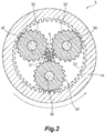
- Fig. 2 is a cross-sectional view taken along line A-A of Fig. 1 .
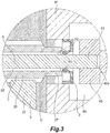
- Fig. 3 is an enlarged cross-sectional view of a region around a portion B illustrated in Fig. 1 .
- Fig. 4 is an enlarged cross-sectional view in accordance with a modified example of the driving apparatus illustrated in Fig. 3 .
- the driving apparatus 100 in accordance with this embodiment is an apparatus that is used for a robot, for example, and that has a configuration in which power from a motor 1 is input to a transmitter 3A including a reduction gear 3, for example, via an input shaft 2, and an output shaft 5 is rotationally driven via the transmitter 3A.
- the driving apparatus 100 includes at least the motor 1, the input shaft 2, the transmitter 3A, and the output shaft 5, and further includes a detector 6 as a more preferable configuration.
- the motor 1 is a servomotor of a synchronous motor that includes at least a rotor 11 having a permanent magnet arranged thereon, a stator 12 having a coil arranged thereon, and a casing 13 housing them.
- an electric motor is used for the motor 1, an air motor that uses air as power, a hydraulic motor that uses hydraulic pressure as power, or the like can also be used.
- the rotor 11 of the motor 1 has a first shaft 24 coupled thereto.
- a tip end of the first shaft 24, located on one side of the motor 1, has a second shaft 25 integrally attached thereto via an attachment 26.
- the first shaft 24 and the second shaft 25 form the input shaft 2 that inputs the power of the motor 1 to the reduction gear 3 of the transmitter 3A.
- the input shaft 2 is substantially cylindrical in shape, and rotates about the rotation axis L as the motor 1 is rotationally driven.
- the input shaft 2 has a hollow space 22 formed therein that penetrates through the input shaft 2 in the axial direction (the direction of the axis), and the output shaft 5 is inserted through the hollow space 22.
- the axial direction is the direction that serves as the central line of a rotational motion when the input shaft 2 rotates, and that coincides with the rotation axis L.
- the input shaft 2 through which the output shaft 5 is inserted is arranged such that the input shaft 2 penetrates through the opposite sides of the motor 1.
- the transmitter 3A which transmits the rotation of the input shaft 2 to the output shaft 5, is arranged on one side of the motor 1, that is, the other side of the input shaft 2.
- One side of the motor 1 may be rephrased as the transmitter 3A side of the motor 1.
- the transmitter 3A may include the reduction gear 3.
- the reduction gear 3 receives the power of the motor 1 from the input shaft 2.
- a planetary gear mechanism is used for the reduction gear 3 in this embodiment, a harmonic gear mechanism or a mechanical reduction gear may also be used, for example.
- the planetary gear mechanism in accordance with this embodiment includes a sun gear 31 that rotates about the rotation axis L, three planet gears 32 that rotate while meshing with the sun gear 31, and an internal gear 33 that rotates while meshing with the three planet gears 32.
- the sun gear 31 is formed on the input shaft 2 (specifically, the second shaft 25), and the internal gear 33 is formed on a cover 34 of the reduction gear 3.
- Each of the three planet gears 32 is coupled to a planet carrier 36 so as to be rotatable.
- the power of the motor 1 transmitted from the input shaft 2 is transmitted to the reduction gear 3, and with the transmitted power, the cover 34, which has the internal gear 33 formed thereon, rotates about the rotation axis L.
- Lubricant G such as grease or oil like oil mist, is housed within the reduction gear 3, and the input shaft 2 is connected to the reduction gear 3 as a tip end 27 of the input shaft 2 is inserted into the reduction gear 3.
- the input shaft 2 is supported by the planet gears 32 of the reduction gear 3.
- the sun gear 31 is formed on the input shaft 2 in this embodiment, the sun gear 31 and the input shaft 2 may be formed as separate members and coupled together.
- the planet carriers 36 and the cover 34 that partially form the reduction gear 3 can be selectively fixed.
- the planet gears 32 and the internal gear 33 can independently revolve about the sun gear 31.
- the planet gears 32 and the internal gear 33 can integrally revolve about the sun gear 31. In this manner, the reduction gear ratio of the reduction gear 3 can be changed.
- the cover 34 of the reduction gear 3 is coupled to one side of a coupling 45 via a plate-like first power transmission member 35, a cylindrical second power transmission member 41, and a third power transmission member 42. Accordingly, the rotation of the cover 34 of the reduction gear 3 can be transmitted to the output shaft 5.
- one of the first, second, and third power transmission members 35, 41, and 42 may partially form a robot body (not illustrated), or one of them may be connected to the robot body. Consequently, the robot can be operated as the cover 34 rotates.
- a joint housing chamber 46 for housing the coupling 45 is formed in an internal space that is formed by the second power transmission member 41 and the third power transmission member 42.
- the coupling 45 arranged in the joint housing chamber 46 couples the third power transmission member 42 to the output shaft 5 on one side of the input shaft 2 that is one side of the motor 1.
- the coupling 45 transmits the power output from the reduction gear 3 to the output shaft 5.
- the output shaft 5 can rotate about the rotation axis L.
- eccentricity of the output shaft 5 with respect to the rotation axis L can be adjusted.
- the transmitter 3A includes the reduction gear 3, the first, second, and third power transmission members 35, 41, 42, and the coupling 45
- the configuration of the transmitter 3A is not particularly limited as long as the transmitter 3A includes at least the reduction gear 3 and the coupling 45, and can transmit the rotation of the input shaft 2 to the output shaft 5.
- the output shaft 5 is an elongated cylindrical member, and is inserted through the hollow space 22 of the input shaft 2 without contacting the input shaft 2, so as to rotate with the power output from the reduction gear 3.
- the output shaft 5 is longer than the input shaft 2, and an end of the output shaft 5 protrudes beyond an end of the input shaft 2.
- the opposite ends of the output shaft 5 may protrude beyond the opposite ends of the input shaft 2. If the output shaft 5 protrudes on one side of the motor 1, the protruding portion (protrusion) that is the tip end 51 of the output shaft 5 protrudes beyond the reduction gear 3 and the hollow space 22 on the reduction gear 3 side, and this portion is coupled to the coupling 45.
- the tip end 51 on one side of the output shaft 5 may protrude beyond the hollow space 22 and be connected to the coupling 45 as described above.
- a portion on the other side of the output shaft 5 may also protrude beyond the hollow space 22 toward the detector 6 side.
- the output shaft 5 may be supported by a bearing (first bearing) 4, on the protrusion protruding beyond the hollow space 22 toward the detector 6.
- the detector 6, which detects rotation information (information on the rotation) of the input shaft and the output shaft, is arranged on the other side of the motor 1, that is, the other side of the input shaft 2.
- the other side of the motor 1 may be rephrased as the detector side of the motor 1.
- the detector 6 includes a first detector 61 and a second detector 65.
- the first detector 61 detects information on the rotation (for example, the direction of the rotation, the angular position, and the number of revolutions) of the input shaft 2.
- the first detector 61 includes a rotating hub 62, a scale 63, and a sensor (rotation detector) 64.
- the rotating hub 62 is fixed on an end of the input shaft 2, and the disk-like scale 63 is fixed on the rotating hub 62. Accordingly, the input shaft 2, the rotating hub 62, and the scale 63 are integrally rotatable.
- the rotation detector 64 is fixed at a position opposite the scale 63.
- the rotation detector 64 is a photodetector or a magnetic detector, for example.
- the rotation detector 64 is a photodetector
- the surface of the scale 63 is irradiated with a detection beam, and the detection beam reflected by an index pattern formed on the surface is received by light-receiving elements, such as photodiodes, for example.
- the rotation detector 64 can detect information on the rotation of the input shaft 2.
- the second detector 65 detects information on the rotation (for example, the direction of the rotation, the angular position, and the number of revolutions) of the output shaft 5.
- the second detector 65 includes a rotating hub 66, a scale 67, and a sensor (rotation detector) 68.
- the second detector 65 can detect information on the rotation of the output shaft 5 on the basis of the same principle as the first detector 61. It should be noted that the principle of detecting, with the first detector 61, information on the rotation of the input shaft 2 may differ from the principle of detecting, with the second detector 65, information on the rotation of the output shaft 5.
- a first limiting member 9 is arranged on one side of the motor 1.
- the first limiting member 9 is, for example, press-fitted into the second power transmission member 41.
- the first limiting member 9 is arranged between the reduction gear 3 and the coupling 45, and limits (suppresses) the movement (intrusion) of foreign matter from the reduction gear 3 into the joint housing chamber 46 of the coupling 45 (toward the coupling 45 side).
- Foreign matter is discharged from, for example, the reduction gear.
- the foreign matter include powder and a fluid, such as the lubricant G, in the reduction gear 3.
- the foreign matter is a contaminant, for example.
- the first limiting member 9 can prevent such adverse effect on the apparatus by suppressing the movement of foreign matter from the reduction gear 3 toward the coupling 45.
- the first limiting member 9 may be, for example, a first blocking member with a first seal.
- the first blocking member include an oil seal (first oil seal) illustrated in Fig. 3 .
- the blocking member is arranged such that it suppresses (blocks) the movement of foreign matter, such as the lubricant G, from the reduction gear 3 toward the coupling 45. If the first blocking member has a target sealing direction, it is arranged in an orientation such that it suppresses the movement of foreign matter, such as the lubricant G, from the reduction gear 3 toward the coupling 45.
- the first blocking member may be any element as long as it can seal oil, for example, an O-ring or a lip packing.
- the seal includes a lip 91, for example.
- the lip 91 is annular in shape, for example, and is in contact with the outer periphery 52 of the output shaft 5 at a position where the inside of the reduction gear 3 is separated from the coupling 45 by the first limiting member 9.
- the lip 91 is made of a flexible elastomer, for example, and is tightly attached to the outer periphery 52 of the output shaft 5. A tip end of the lip 91 is pressed against the outer periphery 52 of the output shaft 5, and has a function of sealing foreign matter.
- the lip 91 has, by maintaining the stable contact state between its tip end and the shaft surface, a function of sealing foreign matter even when machine vibration or fluctuation in the pressure of a sealed fluid occurs.
- the first limiting member 9 may also be a bearing.
- a second limiting member 7 may also be arranged on one side of the motor 1 in the hollow space 22 between the input shaft 2 and the output shaft 5.
- the second limiting member 7 may be a second blocking member, for example, and examples thereof include an oil seal (second oil seal) illustrated in Fig. 4 . If the second limiting member 7 is a second blocking member, the second limiting member 7 is arranged in an orientation such that it limits (blocks) the movement of foreign matter, such as powder or the lubricant G in the reduction gear 3, from the coupling 45 side toward the detector 6 side.
- the tip end 27 of the input shaft 2 has a housing recess 27a formed therein, and the second limiting member 7 is housed in the housing recess 27a.
- the second limiting member 7 may also be a second blocking member with a second seal, for example. If the second blocking member has a target sealing direction, it is arranged in an orientation such that it suppresses (blocks) the movement of foreign matter toward the detector side.
- the second seal has a lip 71, for example.
- the lip 71 is annular in shape, for example, and is in contact with the outer periphery 52 of the output shaft 5 at a position where the lip 71 separates the hollow space 22 from its outside.
- the lip 71 is made of a flexible elastomer, for example, and is tightly attached to the outer periphery 52 of the output shaft 5. A tip end of the lip is pressed against the outer periphery 52 of the output shaft 5, and has a function of sealing foreign matter.
- the second limiting member 7 may also be a bearing.
- each of the first limiting member 9 and the second limiting member 7 can specify the direction of intrusion of foreign matter, and thus limit (prevent) the intrusion of the foreign matter further reliably.
- a seal bearing or a labyrinth structure for example, can also be adopted as long as it can limit the intrusion of foreign matter in the aforementioned direction.
- the driving apparatus can be used for faster rotations as the first limiting member 9 is not in contact with the input shaft 2 or the output shaft 5.
- the first limiting member 9 is a labyrinth structure
- the first limiting member 9 has a plurality of protrusions and the second power transmission member 41 also as a plurality of protrusions.
- the protrusions of the first limiting member 9 and the protrusions of the second power transmission member 41 are arranged such that they are alternately combined with small gaps therebetween. With such a first limiting member 9, the movement of foreign matter, which has been discharged from the reduction gear 3, toward the coupling 45 can be limited.
- the input shaft 2 rotates about the rotation axis L.
- the power of the motor 1 is input to the reduction gear 3 from the input shaft 2.
- the cover 34 of the reduction gear 3 rotates the number of times corresponding to the reduction gear ratio.
- the output shaft 5, which is coupled to the cover 34 via the first, second, and third power transmission members 35, 41, and 42 and the coupling 45 rotates the same number of times as the cover 34.
- the rotating hub 62 and the scale 63 rotate with the rotation of the input shaft 2, and the rotation detector 64 detects information on the rotation of the input shaft 2.
- the rotating hub 66 and the scale 67 rotate with the rotation of the output shaft 5, and the rotation detector 68 detects information on the rotation of the output shaft 5.
- the driving apparatus 100 when the driving apparatus 100 is operated, a decrease in the rotation accuracy of the input shaft 2 and the output shaft 5 due to the intrusion of foreign matter, such as the lubricant G, can be suppressed.
- the lubricant G in the reduction gear 3 is grease
- viscous drag would be generated on the coupling 45 upon intrusion of the grease as foreign matter into the coupling side.
- using the first limiting member 9 can suppress such a phenomenon and thus enhance the rotation accuracy of the output shaft 5.
- the second limiting member 7 is arranged in the hollow space 22 between the input shaft 2 and the output shaft 5, the intrusion of foreign matter, such as the lubricant G, in the reduction gear 3 into the hollow space 22 of the input shaft 2 can be limited. Accordingly, contamination of the detector 6 can be prevented.
- using two limiting members including the first limiting member 9 and the second limiting member 7 can suppress the movement of foreign matter, such as the lubricant G, to an unwanted place from the reduction gear 3.
- Fig. 5 is a schematic cross-sectional view illustrating the entire configuration of a driving apparatus in accordance with the second embodiment.
- Fig. 6 is an enlarged view of a region around a portion C illustrated in Fig. 5 .
- Fig. 7 is an enlarged cross-sectional view in accordance with a modified example of the driving apparatus illustrated in Fig. 6 .
- the driving apparatus 100 in the second embodiment differs from that in the first embodiment in the position of the first limiting member 9. Therefore, in this embodiment, elements that are the same as or equivalent to those in the first embodiment are denoted by the same reference numerals, and the description thereof will be omitted or simplified.
- the first limiting member 9 is arranged between the reduction gear 3 and the coupling 45, so as to limit (suppress) the movement (intrusion) of foreign matter from the reduction gear 3 into the joint housing chamber 46 of the coupling 45 (toward the coupling 45 side).
- the first limiting member 9 may be, for example, a blocking member with a seal. If the blocking member has a target sealing direction, it is arranged in an orientation such that it limits the intrusion of foreign matter, such as the lubricant G, in the reduction gear 3 into the joint housing chamber 46 of the coupling 45 (toward the coupling 45 side). This point is similar to the first limiting member in accordance with the first embodiment.
- the first limiting member 9 is attached such that it contacts the outer periphery of the input shaft. Accordingly, the first limiting member 9 can suppress the flow of foreign matter, such as the lubricant G, from the inside of the reduction gear 3 into the hollow space 22 of the input shaft 2, without contacting the output shaft 5.
- the first limiting member 9 is a blocking member with a seal, for example, and the seal includes a lip 91, for example.
- the lip 91 is in contact with the outer periphery 28 of the input shaft 2 at a position where the inside of the reduction gear 3 is separated from the coupling 45 by the first limiting member 9.
- the lip 91 is made of a flexible elastomer, for example, and is tightly attached to the outer periphery 52 of the input shaft 2.
- the second limiting member 7 may also be provided.
- the driving apparatus 100 has a structure in which the first limiting member 9 and the second limiting member 7 are arranged in this order on a route through which foreign matter, such as the lubricant G, flows from the inside of the reduction gear 3 toward the hollow space 22 of the input shaft 2. Accordingly, the movement of foreign matter, which has been discharged from the inside of the reduction gear 3, to the detector 6 through the input shaft 2 can be further limited.
- the second limiting member 7 which is arranged on the tip end 27 of the input shaft 2 is present on the route.
- the first limiting member 9 prevents the flow of foreign matter, such as the lubricant G, from the inside of the reduction gear 3 to the tip end 27 of the input shaft 2. Therefore, foreign matter does not flow into the hollow space 22 of the input shaft 2 regardless of whether the seal property of the second limiting member 7 has deteriorated or not.
- the intrusion of foreign matter, such as the lubricant G, into the hollow space 22 of the input shaft 2 can be limited as long as the seal property of the other limiting member is ensured. Accordingly, contamination of the detector can be prevented.
- Fig. 8 is a schematic cross-sectional view illustrating the entire configuration of a driving apparatus in accordance with the third embodiment.
- Fig. 9 is an enlarged view of a region around a portion D illustrated in Fig. 8 .
- the driving apparatus 100 in the third embodiment differs from that in the second embodiment in that a second bearing 8 is further provided. Therefore, in this embodiment, elements that are the same as or equivalent to those in the second embodiment are denoted by the same reference numerals, and the description thereof will be omitted or simplified.
- the second bearing 8 that supports the output shaft 5 is further arranged on one side of the motor 1. More specifically, the second bearing 8 is arranged at a position adjacent to the second limiting member 7 such that the second bearing 8 is closer to the tip end 27b side of the input shaft 2 than is the second limiting member 7, in the hollow space 22 between the input shaft 2 and the output shaft 5.
- the output shaft 5 is supported by the first bearing 4 and the second bearing 8 with the motor 1 interposed therebetween, whirling of the output shaft 5 can be suppressed during operation of the driving apparatus 100. Accordingly, there is no possibility that the second limiting member 7 arranged in the hollow space 22 between the input shaft 2 and the output shaft 5 will deform excessively due to the whirling of the output shaft 5. Consequently, the seal property of the second limiting member can be maintained.
- the second bearing 8 is arranged at a position adjacent to the second limiting member 7, it is possible to suppress the excessive deformation of the second limiting member 7 and maintain the seal property of the second limiting member even more.
- the second bearing 8 is arranged closer to the tip end 27b side of the input shaft 2 than is the second limiting member 7, foreign matter, such as the lubricant G, which is about to intrude into the hollow space 22 of the input shaft 2, contacts the second limiting member 7 via the second bearing 8. Accordingly, even when excessive pressure is generated in the grease while the foreign matter is flowing, such pressure can be once received by the second bearing 8, and thus, positional deviation of the second limiting member 7 can be avoided. Consequently, the reliability of the second limiting member 7 can be maintained.
- the output shaft is supported only by the first bearing, but the second bearing may be further provided as illustrated in the third embodiment.
- the second bearing is arranged in the hollow space between the input shaft and the output shaft, but the second bearing may also be arranged between the tip end of the input shaft and the coupling, for example.
- the second bearing is arranged closer to the tip end side of the input shaft than is the second limiting member, but the second limiting member may be arranged closer to the tip end side of the input shaft than is the second bearing.
Landscapes
- Engineering & Computer Science (AREA)
- General Engineering & Computer Science (AREA)
- Power Engineering (AREA)
- Mechanical Engineering (AREA)
- Microelectronics & Electronic Packaging (AREA)
- Robotics (AREA)
- General Details Of Gearings (AREA)
- Connection Of Motors, Electrical Generators, Mechanical Devices, And The Like (AREA)
- Manipulator (AREA)
- Retarders (AREA)
- Sealing Of Bearings (AREA)
Abstract
Description
- The present invention relates to a driving apparatus that is suitably used for industrial robots, for example.
- Conventionally, driving apparatuses have been used to drive industrial robots. For example, Patent Literature 1 proposes a driving apparatus including an input shaft that rotates with the power of a motor, a reduction gear that receives the power of the motor from the input shaft, and an output shaft that rotates with the power output from the reduction gear.
- The input shaft of the driving apparatus has a hollow space formed therein that penetrates through the input shaft in the axial direction, and the output shaft is inserted through the hollow space. The reduction gear is arranged on one side of the motor, and a detector, which detects information on the rotation of the input shaft and the output shaft, is arranged on the other side of the motor.
- Patent Literature 1:
JP 2522495 Y2 - By the way, for this type of driving apparatus, a structure may be adopted in which a coupling is attached to a tip end of the output shaft so as to transmit the power output from the reduction gear to the output shaft. However, if foreign matter from the reduction gear intrudes into the coupling side, the rotation accuracy of the output shaft may be adversely affected.
- According to the first aspect of the present invention, there is provided a driving apparatus including an input shaft with a hollow space; a motor configured to rotate the input shaft; a reduction gear arranged on one side of the motor, the reduction gear being configured to receive the power of the motor from the input shaft; an output shaft inserted through the hollow space of the input shaft, the output shaft being adapted to rotate about the rotation axis of the motor; a coupling connected to a tip end of the output shaft on the one side of the motor; and a detector provided on another side of the motor, the detector being configured to detect information on the rotation of the input shaft and information on the rotation of the output shaft, in which a first limiting member is arranged between the reduction gear and the coupling, the first limiting member being adapted to limit movement of foreign matter toward the coupling side.
- According to the second aspect of the present invention, there is provided a driving apparatus including an input shaft with a hollow space formed therein, the hollow space penetrating through the input shaft in the axial direction; a motor configured to rotate the input shaft about the rotation axis along the axial direction; a reduction gear arranged on one side of the motor, the reduction gear being configured to receive the power of the motor from the input shaft; an output shaft inserted through the hollow space of the input shaft, the output shaft being adapted to rotate about the rotation axis with the power output from the reduction gear; a coupling connected to the output shaft on the one side of the motor so as to transmit the power output from the reduction gear to the output shaft; and a detector provided on another side of the motor, the detector being configured to detect information on the rotation of the input shaft and information on the rotation of the output shaft, in which the inside of the reduction gear is filled with grease, the input shaft being arranged such that the input shaft penetrates through the inside of the reduction gear, a first oil seal is arranged between the reduction gear and the coupling, the first oil seal being adapted to limit the intrusion of the grease in the reduction gear into the coupling side, and a second oil seal is arranged in the hollow space between the input shaft and the output shaft, the second oil seal being adapted to limit the intrusion of the grease into the hollow space.
- According to the third aspect of the present invention, there is provided a a driving apparatus including an input shaft with a hollow space formed therein; a motor configured to rotate the input shaft; a reduction gear arranged on one side of the input shaft, the reduction gear being configured to receive the power of the motor from the input shaft; an output shaft inserted through the hollow space of the input shaft, the output shaft being adapted to rotate with the power output from the reduction gear; a coupling connected to the output shaft on the one side of the input shaft; and a limiting member arranged between the reduction gear and the coupling, the limiting member being adapted to limit the intrusion of foreign matter into the coupling.
-
-
Fig. 1 is a schematic cross-sectional view illustrating the entire configuration of a driving apparatus in accordance with the first embodiment. -
Fig. 2 is a cross-sectional view taken along line A-A ofFig. 1 . -
Fig. 3 is an enlarged cross-sectional view of a region around a portion B illustrated inFig. 1 . -
Fig. 4 is an enlarged cross-sectional view in accordance with a modified example of the driving apparatus illustrated inFig. 3 . -
Fig. 5 is a schematic cross-sectional view illustrating the entire configuration of a driving apparatus in accordance with the second embodiment. -
Fig. 6 is an enlarged view of a region around a portion C illustrated inFig. 5 . -
Fig. 7 is an enlarged cross-sectional view in accordance with a modified example of the driving apparatus illustrated inFig. 6 . -
Fig. 8 is a schematic cross-sectional view illustrating the entire configuration of a driving apparatus in accordance with the third embodiment. -
Fig. 9 is an enlarged view of a region around a portion D illustrated inFig. 8 . - Hereinafter, several embodiments for carrying out the present invention will be described with reference to
Figs. 1 to 9 . It should be noted that the scope of the present invention is not limited to the following embodiments, and can be changed as appropriate within the spirit and scope of the present invention. -
Fig. 1 is a schematic cross-sectional view illustrating the entire configuration of adriving apparatus 100 in accordance with the first embodiment.Fig. 2 is a cross-sectional view taken along line A-A ofFig. 1 .Fig. 3 is an enlarged cross-sectional view of a region around a portion B illustrated inFig. 1 .Fig. 4 is an enlarged cross-sectional view in accordance with a modified example of the driving apparatus illustrated inFig. 3 . - As illustrated in
Fig. 1 , thedriving apparatus 100 in accordance with this embodiment is an apparatus that is used for a robot, for example, and that has a configuration in which power from a motor 1 is input to atransmitter 3A including areduction gear 3, for example, via aninput shaft 2, and anoutput shaft 5 is rotationally driven via thetransmitter 3A. Thedriving apparatus 100 includes at least the motor 1, theinput shaft 2, thetransmitter 3A, and theoutput shaft 5, and further includes adetector 6 as a more preferable configuration. - The motor 1 is a servomotor of a synchronous motor that includes at least a
rotor 11 having a permanent magnet arranged thereon, astator 12 having a coil arranged thereon, and acasing 13 housing them. In this embodiment, although an electric motor is used for the motor 1, an air motor that uses air as power, a hydraulic motor that uses hydraulic pressure as power, or the like can also be used. - The
rotor 11 of the motor 1 has afirst shaft 24 coupled thereto. A tip end of thefirst shaft 24, located on one side of the motor 1, has asecond shaft 25 integrally attached thereto via anattachment 26. In this embodiment, thefirst shaft 24 and thesecond shaft 25 form theinput shaft 2 that inputs the power of the motor 1 to thereduction gear 3 of thetransmitter 3A. - The
input shaft 2 is substantially cylindrical in shape, and rotates about the rotation axis L as the motor 1 is rotationally driven. Theinput shaft 2 has ahollow space 22 formed therein that penetrates through theinput shaft 2 in the axial direction (the direction of the axis), and theoutput shaft 5 is inserted through thehollow space 22. It should be noted that the axial direction is the direction that serves as the central line of a rotational motion when theinput shaft 2 rotates, and that coincides with the rotation axis L. Theinput shaft 2 through which theoutput shaft 5 is inserted is arranged such that theinput shaft 2 penetrates through the opposite sides of the motor 1. - The
transmitter 3A, which transmits the rotation of theinput shaft 2 to theoutput shaft 5, is arranged on one side of the motor 1, that is, the other side of theinput shaft 2. One side of the motor 1 may be rephrased as thetransmitter 3A side of the motor 1. Thetransmitter 3A may include thereduction gear 3. Thereduction gear 3 receives the power of the motor 1 from theinput shaft 2. Although a planetary gear mechanism is used for thereduction gear 3 in this embodiment, a harmonic gear mechanism or a mechanical reduction gear may also be used, for example. - As illustrated in
Fig. 2 , the planetary gear mechanism in accordance with this embodiment includes asun gear 31 that rotates about the rotation axis L, threeplanet gears 32 that rotate while meshing with thesun gear 31, and aninternal gear 33 that rotates while meshing with the threeplanet gears 32. Thesun gear 31 is formed on the input shaft 2 (specifically, the second shaft 25), and theinternal gear 33 is formed on acover 34 of thereduction gear 3. Each of the threeplanet gears 32 is coupled to aplanet carrier 36 so as to be rotatable. - With the aforementioned configuration, the power of the motor 1 transmitted from the
input shaft 2 is transmitted to thereduction gear 3, and with the transmitted power, thecover 34, which has theinternal gear 33 formed thereon, rotates about the rotation axis L. Lubricant G, such as grease or oil like oil mist, is housed within thereduction gear 3, and theinput shaft 2 is connected to thereduction gear 3 as atip end 27 of theinput shaft 2 is inserted into thereduction gear 3. When theinput shaft 2 is connected to thereduction gear 3, theinput shaft 2 is supported by theplanet gears 32 of thereduction gear 3. Although thesun gear 31 is formed on theinput shaft 2 in this embodiment, thesun gear 31 and theinput shaft 2 may be formed as separate members and coupled together. - The planet carriers 36 and the
cover 34 that partially form thereduction gear 3 can be selectively fixed. When theplanet carriers 36 and thecover 34 are not fixed, theplanet gears 32 and theinternal gear 33 can independently revolve about thesun gear 31. Meanwhile, when theplanet carriers 36 and thecover 34 are fixed, theplanet gears 32 and theinternal gear 33 can integrally revolve about thesun gear 31. In this manner, the reduction gear ratio of thereduction gear 3 can be changed. - The
cover 34 of thereduction gear 3 is coupled to one side of acoupling 45 via a plate-like firstpower transmission member 35, a cylindrical secondpower transmission member 41, and a thirdpower transmission member 42. Accordingly, the rotation of thecover 34 of thereduction gear 3 can be transmitted to theoutput shaft 5. It should be noted that one of the first, second, and thirdpower transmission members cover 34 rotates. - A
joint housing chamber 46 for housing thecoupling 45 is formed in an internal space that is formed by the secondpower transmission member 41 and the thirdpower transmission member 42. Thecoupling 45 arranged in thejoint housing chamber 46 couples the thirdpower transmission member 42 to theoutput shaft 5 on one side of theinput shaft 2 that is one side of the motor 1. With such a configuration, thecoupling 45 transmits the power output from thereduction gear 3 to theoutput shaft 5. With the power output from thereduction gear 3, theoutput shaft 5 can rotate about the rotation axis L. In addition, since atip end 51 of theoutput shaft 5 is coupled to thecoupling 45, eccentricity of theoutput shaft 5 with respect to the rotation axis L can be adjusted. Although thetransmitter 3A includes thereduction gear 3, the first, second, and thirdpower transmission members coupling 45, for example, the configuration of thetransmitter 3A is not particularly limited as long as thetransmitter 3A includes at least thereduction gear 3 and thecoupling 45, and can transmit the rotation of theinput shaft 2 to theoutput shaft 5. - The
output shaft 5 is an elongated cylindrical member, and is inserted through thehollow space 22 of theinput shaft 2 without contacting theinput shaft 2, so as to rotate with the power output from thereduction gear 3. Theoutput shaft 5 is longer than theinput shaft 2, and an end of theoutput shaft 5 protrudes beyond an end of theinput shaft 2. The opposite ends of theoutput shaft 5 may protrude beyond the opposite ends of theinput shaft 2. If theoutput shaft 5 protrudes on one side of the motor 1, the protruding portion (protrusion) that is thetip end 51 of theoutput shaft 5 protrudes beyond thereduction gear 3 and thehollow space 22 on thereduction gear 3 side, and this portion is coupled to thecoupling 45. Thetip end 51 on one side of theoutput shaft 5 may protrude beyond thehollow space 22 and be connected to thecoupling 45 as described above. In addition, a portion on the other side of theoutput shaft 5 may also protrude beyond thehollow space 22 toward thedetector 6 side. Theoutput shaft 5 may be supported by a bearing (first bearing) 4, on the protrusion protruding beyond thehollow space 22 toward thedetector 6. - More preferably, the
detector 6, which detects rotation information (information on the rotation) of the input shaft and the output shaft, is arranged on the other side of the motor 1, that is, the other side of theinput shaft 2. The other side of the motor 1 may be rephrased as the detector side of the motor 1. Thedetector 6 includes afirst detector 61 and asecond detector 65. Thefirst detector 61 detects information on the rotation (for example, the direction of the rotation, the angular position, and the number of revolutions) of theinput shaft 2. Thefirst detector 61 includes a rotatinghub 62, ascale 63, and a sensor (rotation detector) 64. The rotatinghub 62 is fixed on an end of theinput shaft 2, and the disk-like scale 63 is fixed on the rotatinghub 62. Accordingly, theinput shaft 2, the rotatinghub 62, and thescale 63 are integrally rotatable. - The
rotation detector 64 is fixed at a position opposite thescale 63. Therotation detector 64 is a photodetector or a magnetic detector, for example. For example, when therotation detector 64 is a photodetector, the surface of thescale 63 is irradiated with a detection beam, and the detection beam reflected by an index pattern formed on the surface is received by light-receiving elements, such as photodiodes, for example. Therotation detector 64 can detect information on the rotation of theinput shaft 2. - The
second detector 65 detects information on the rotation (for example, the direction of the rotation, the angular position, and the number of revolutions) of theoutput shaft 5. Thesecond detector 65 includes a rotatinghub 66, ascale 67, and a sensor (rotation detector) 68. Thesecond detector 65 can detect information on the rotation of theoutput shaft 5 on the basis of the same principle as thefirst detector 61. It should be noted that the principle of detecting, with thefirst detector 61, information on the rotation of theinput shaft 2 may differ from the principle of detecting, with thesecond detector 65, information on the rotation of theoutput shaft 5. - As illustrated in
Fig. 3 , a first limitingmember 9 is arranged on one side of the motor 1. The first limitingmember 9 is, for example, press-fitted into the secondpower transmission member 41. The first limitingmember 9 is arranged between thereduction gear 3 and thecoupling 45, and limits (suppresses) the movement (intrusion) of foreign matter from thereduction gear 3 into thejoint housing chamber 46 of the coupling 45 (toward thecoupling 45 side). Foreign matter is discharged from, for example, the reduction gear. Examples of the foreign matter include powder and a fluid, such as the lubricant G, in thereduction gear 3. In addition, the foreign matter is a contaminant, for example. If the foreign matter moves toward thecoupling 45 or thedetector 6, the rotation of the shafts or the operation of the apparatus, such as detection of information on the rotation, may be adversely affected. Therefore, the first limitingmember 9 can prevent such adverse effect on the apparatus by suppressing the movement of foreign matter from thereduction gear 3 toward thecoupling 45. - The first limiting
member 9 may be, for example, a first blocking member with a first seal. Examples of the first blocking member include an oil seal (first oil seal) illustrated inFig. 3 . The blocking member is arranged such that it suppresses (blocks) the movement of foreign matter, such as the lubricant G, from thereduction gear 3 toward thecoupling 45. If the first blocking member has a target sealing direction, it is arranged in an orientation such that it suppresses the movement of foreign matter, such as the lubricant G, from thereduction gear 3 toward thecoupling 45. It should be noted that the first blocking member may be any element as long as it can seal oil, for example, an O-ring or a lip packing. - The seal includes a
lip 91, for example. Thelip 91 is annular in shape, for example, and is in contact with theouter periphery 52 of theoutput shaft 5 at a position where the inside of thereduction gear 3 is separated from thecoupling 45 by the first limitingmember 9. Thelip 91 is made of a flexible elastomer, for example, and is tightly attached to theouter periphery 52 of theoutput shaft 5. A tip end of thelip 91 is pressed against theouter periphery 52 of theoutput shaft 5, and has a function of sealing foreign matter. Thelip 91 has, by maintaining the stable contact state between its tip end and the shaft surface, a function of sealing foreign matter even when machine vibration or fluctuation in the pressure of a sealed fluid occurs. In addition, the first limitingmember 9 may also be a bearing. - Further, as in a modified example illustrated in
Fig. 4 , a second limitingmember 7 may also be arranged on one side of the motor 1 in thehollow space 22 between theinput shaft 2 and theoutput shaft 5. The second limitingmember 7 may be a second blocking member, for example, and examples thereof include an oil seal (second oil seal) illustrated inFig. 4 . If the second limitingmember 7 is a second blocking member, the second limitingmember 7 is arranged in an orientation such that it limits (blocks) the movement of foreign matter, such as powder or the lubricant G in thereduction gear 3, from thecoupling 45 side toward thedetector 6 side. - Specifically, the
tip end 27 of theinput shaft 2 has ahousing recess 27a formed therein, and the second limitingmember 7 is housed in thehousing recess 27a. The second limitingmember 7 may also be a second blocking member with a second seal, for example. If the second blocking member has a target sealing direction, it is arranged in an orientation such that it suppresses (blocks) the movement of foreign matter toward the detector side. - The second seal has a
lip 71, for example. Thelip 71 is annular in shape, for example, and is in contact with theouter periphery 52 of theoutput shaft 5 at a position where thelip 71 separates thehollow space 22 from its outside. Thelip 71 is made of a flexible elastomer, for example, and is tightly attached to theouter periphery 52 of theoutput shaft 5. A tip end of the lip is pressed against theouter periphery 52 of theoutput shaft 5, and has a function of sealing foreign matter. In addition, the second limitingmember 7 may also be a bearing. - It should be noted that in the present modified example, using an oil seal as each of the first limiting
member 9 and the second limitingmember 7 can specify the direction of intrusion of foreign matter, and thus limit (prevent) the intrusion of the foreign matter further reliably. Further, a seal bearing or a labyrinth structure, for example, can also be adopted as long as it can limit the intrusion of foreign matter in the aforementioned direction. - If the first limiting
member 9 and/or the second limitingmember 7 are/is a labyrinth structure(s), the driving apparatus can be used for faster rotations as the first limitingmember 9 is not in contact with theinput shaft 2 or theoutput shaft 5. For example, if the first limitingmember 9 is a labyrinth structure, the first limitingmember 9 has a plurality of protrusions and the secondpower transmission member 41 also as a plurality of protrusions. The protrusions of the first limitingmember 9 and the protrusions of the secondpower transmission member 41 are arranged such that they are alternately combined with small gaps therebetween. With such a first limitingmember 9, the movement of foreign matter, which has been discharged from thereduction gear 3, toward thecoupling 45 can be limited. - Hereinafter, the operation of the driving
apparatus 100 in this embodiment will be described. - First, when the motor 1 is driven, the
input shaft 2 rotates about the rotation axis L. With the rotation of theinput shaft 2, the power of the motor 1 is input to thereduction gear 3 from theinput shaft 2. With the power input to thereduction gear 3, thecover 34 of thereduction gear 3 rotates the number of times corresponding to the reduction gear ratio. With the rotation of thecover 34, theoutput shaft 5, which is coupled to thecover 34 via the first, second, and thirdpower transmission members coupling 45, rotates the same number of times as thecover 34. - In the
first detector 61, the rotatinghub 62 and thescale 63 rotate with the rotation of theinput shaft 2, and therotation detector 64 detects information on the rotation of theinput shaft 2. Meanwhile, in thesecond detector 65, the rotatinghub 66 and thescale 67 rotate with the rotation of theoutput shaft 5, and therotation detector 68 detects information on the rotation of theoutput shaft 5. - Herein, during operation of the driving
apparatus 100, there may be cases where foreign matter, such as the lubricant G, in thereduction gear 3 may flow through a region between the secondpower transmission member 41 and theinput shaft 2. Even in such a case, since the first limitingmember 9 is arranged between thereduction gear 3 and thecoupling 45, the intrusion (movement) of foreign matter, such as the lubricant G, in thereduction gear 3 into the joint housing chamber 46 (toward thecoupling 45 side) can be limited. - Accordingly, when the driving
apparatus 100 is operated, a decrease in the rotation accuracy of theinput shaft 2 and theoutput shaft 5 due to the intrusion of foreign matter, such as the lubricant G, can be suppressed. In particular, if the lubricant G in thereduction gear 3 is grease, viscous drag would be generated on thecoupling 45 upon intrusion of the grease as foreign matter into the coupling side. However, using the first limitingmember 9 can suppress such a phenomenon and thus enhance the rotation accuracy of theoutput shaft 5. - In addition, since the second limiting
member 7 is arranged in thehollow space 22 between theinput shaft 2 and theoutput shaft 5, the intrusion of foreign matter, such as the lubricant G, in thereduction gear 3 into thehollow space 22 of theinput shaft 2 can be limited. Accordingly, contamination of thedetector 6 can be prevented. - As described above, using two limiting members including the first limiting
member 9 and the second limitingmember 7 can suppress the movement of foreign matter, such as the lubricant G, to an unwanted place from thereduction gear 3. -
Fig. 5 is a schematic cross-sectional view illustrating the entire configuration of a driving apparatus in accordance with the second embodiment.Fig. 6 is an enlarged view of a region around a portion C illustrated inFig. 5 .Fig. 7 is an enlarged cross-sectional view in accordance with a modified example of the driving apparatus illustrated inFig. 6 . The drivingapparatus 100 in the second embodiment differs from that in the first embodiment in the position of the first limitingmember 9. Therefore, in this embodiment, elements that are the same as or equivalent to those in the first embodiment are denoted by the same reference numerals, and the description thereof will be omitted or simplified. - As illustrated in
Fig. 6 , in thedriving apparatus 100 in accordance with the second embodiment, the first limitingmember 9 is arranged between thereduction gear 3 and thecoupling 45, so as to limit (suppress) the movement (intrusion) of foreign matter from thereduction gear 3 into thejoint housing chamber 46 of the coupling 45 (toward thecoupling 45 side). The first limitingmember 9 may be, for example, a blocking member with a seal. If the blocking member has a target sealing direction, it is arranged in an orientation such that it limits the intrusion of foreign matter, such as the lubricant G, in thereduction gear 3 into thejoint housing chamber 46 of the coupling 45 (toward thecoupling 45 side). This point is similar to the first limiting member in accordance with the first embodiment. - In this embodiment, the first limiting
member 9 is attached such that it contacts the outer periphery of the input shaft. Accordingly, the first limitingmember 9 can suppress the flow of foreign matter, such as the lubricant G, from the inside of thereduction gear 3 into thehollow space 22 of theinput shaft 2, without contacting theoutput shaft 5. The first limitingmember 9 is a blocking member with a seal, for example, and the seal includes alip 91, for example. Thelip 91 is in contact with theouter periphery 28 of theinput shaft 2 at a position where the inside of thereduction gear 3 is separated from thecoupling 45 by the first limitingmember 9. Thelip 91 is made of a flexible elastomer, for example, and is tightly attached to theouter periphery 52 of theinput shaft 2. - In this embodiment, since the first limiting
member 9 is not in contact with theoutput shaft 5, it will not become rotational resistance on theoutput shaft 5. Therefore, the rotation accuracy of theoutput shaft 5 can be further enhanced. - Further, as in the modified example illustrated in
Fig. 7 , the second limitingmember 7 may also be provided. In such a case, the drivingapparatus 100 has a structure in which the first limitingmember 9 and the second limitingmember 7 are arranged in this order on a route through which foreign matter, such as the lubricant G, flows from the inside of thereduction gear 3 toward thehollow space 22 of theinput shaft 2. Accordingly, the movement of foreign matter, which has been discharged from the inside of thereduction gear 3, to thedetector 6 through theinput shaft 2 can be further limited. For example, even when the seal property of the first limitingmember 9 has deteriorated and foreign matter, such as the lubricant G, has flowed out of the inside of thereduction gear 3 into the joint housing chamber 46 (toward thecoupling 45 side), the second limitingmember 7, which is arranged on thetip end 27 of theinput shaft 2, is present on the route. Meanwhile, even when the seal property of the second limitingmember 7 has deteriorated, the first limitingmember 9 prevents the flow of foreign matter, such as the lubricant G, from the inside of thereduction gear 3 to thetip end 27 of theinput shaft 2. Therefore, foreign matter does not flow into thehollow space 22 of theinput shaft 2 regardless of whether the seal property of the second limitingmember 7 has deteriorated or not. - As described above, in the driving apparatus provided with the first limiting
member 9 and the second limitingmember 7, even when the seal property of one of the second limitingmember 7 or the first limitingmember 9 has deteriorated, the intrusion of foreign matter, such as the lubricant G, into thehollow space 22 of theinput shaft 2 can be limited as long as the seal property of the other limiting member is ensured. Accordingly, contamination of the detector can be prevented. -
Fig. 8 is a schematic cross-sectional view illustrating the entire configuration of a driving apparatus in accordance with the third embodiment.Fig. 9 is an enlarged view of a region around a portion D illustrated inFig. 8 . The drivingapparatus 100 in the third embodiment differs from that in the second embodiment in that asecond bearing 8 is further provided. Therefore, in this embodiment, elements that are the same as or equivalent to those in the second embodiment are denoted by the same reference numerals, and the description thereof will be omitted or simplified. - As illustrated in
Figs. 8 and9 , in thedriving apparatus 100 in accordance with the third embodiment, thesecond bearing 8 that supports theoutput shaft 5 is further arranged on one side of the motor 1. More specifically, thesecond bearing 8 is arranged at a position adjacent to the second limitingmember 7 such that thesecond bearing 8 is closer to thetip end 27b side of theinput shaft 2 than is the second limitingmember 7, in thehollow space 22 between theinput shaft 2 and theoutput shaft 5. - As described above, since the
output shaft 5 is supported by thefirst bearing 4 and thesecond bearing 8 with the motor 1 interposed therebetween, whirling of theoutput shaft 5 can be suppressed during operation of the drivingapparatus 100. Accordingly, there is no possibility that the second limitingmember 7 arranged in thehollow space 22 between theinput shaft 2 and theoutput shaft 5 will deform excessively due to the whirling of theoutput shaft 5. Consequently, the seal property of the second limiting member can be maintained. - In particular, in this embodiment, since the
second bearing 8 is arranged at a position adjacent to the second limitingmember 7, it is possible to suppress the excessive deformation of the second limitingmember 7 and maintain the seal property of the second limiting member even more. - Further, since the
second bearing 8 is arranged closer to thetip end 27b side of theinput shaft 2 than is the second limitingmember 7, foreign matter, such as the lubricant G, which is about to intrude into thehollow space 22 of theinput shaft 2, contacts the second limitingmember 7 via thesecond bearing 8. Accordingly, even when excessive pressure is generated in the grease while the foreign matter is flowing, such pressure can be once received by thesecond bearing 8, and thus, positional deviation of the second limitingmember 7 can be avoided. Consequently, the reliability of the second limitingmember 7 can be maintained. - Although the embodiments of the present invention have been described in detail above, the specific configuration of the present invention is not limited thereto, and any design changes that are within the spirit and scope of the present invention are all included in the present invention.
- In the driving apparatus of the first embodiment, the output shaft is supported only by the first bearing, but the second bearing may be further provided as illustrated in the third embodiment. In the third embodiment, the second bearing is arranged in the hollow space between the input shaft and the output shaft, but the second bearing may also be arranged between the tip end of the input shaft and the coupling, for example. Further, in the third embodiment, the second bearing is arranged closer to the tip end side of the input shaft than is the second limiting member, but the second limiting member may be arranged closer to the tip end side of the input shaft than is the second bearing.
-
- 1
- Motor
- 2
- Input shaft
- 3
- Reduction gear
- 4
- First bearing
- 5
- Output shaft
- 6
- Detector
- 7
- Second limiting member
- 8
- Second bearing
- 9
- First limiting member
- 22
- Hollow space
- 45
- Coupling
- G
- Lubricant
- L
- Rotation axis
Claims (15)
- A driving apparatus comprising:an input shaft with a hollow space;a motor configured to rotate the input shaft;a reduction gear arranged on one side of the motor, the reduction gear being configured to receive power of the motor from the input shaft;an output shaft inserted through the hollow space of the input shaft, the output shaft being adapted to rotate about a rotation axis of the motor;a coupling connected to a tip end of the output shaft on the one side of the motor; anda detector provided on another side of the motor, the detector being configured to detect information on rotation of the input shaft and information on rotation of the output shaft,wherein:
a first limiting member is arranged between the reduction gear and the coupling, the first limiting member being adapted to limit movement of foreign matter toward the coupling side. - The driving apparatus according to claim 1,
wherein:the first limiting member is a first blocking member with a first seal, andthe first blocking member blocks movement of foreign matter in the reduction gear toward the coupling side. - The driving apparatus according to claim 2, wherein the first seal is in contact with an outer periphery of the input shaft at a position where the first seal separates an inside of the reduction gear from the coupling.
- The driving apparatus according to claim 2, wherein the first seal is in contact with an outer periphery of the output shaft at a position where the first seal separates an inside of the reduction gear from the coupling.
- The driving apparatus according to any one of claims 1 to 4, wherein a second limiting member is arranged in the hollow space between the input shaft and the output shaft, the second limiting member being adapted to limit movement of the foreign matter from the one side of the motor toward the other side of the motor.
- The driving apparatus according to claim 5,
wherein:the second limiting member is a second blocking member with a second seal, andthe second blocking member blocks movement of foreign matter discharged from the reduction gear toward the detector side. - The driving apparatus according to claim 6, wherein the second seal is in contact with an outer periphery of the output shaft in the hollow space.
- The driving apparatus according to any one of claims 1 to 7,
wherein:a first bearing adapted to support the output shaft is arranged on the other side of the motor, anda second bearing adapted to support the output shaft is arranged on the one side of the motor. - The driving apparatus according to any one of claims 5 to 7,
wherein:a first bearing adapted to support the output shaft is arranged on the other side of the motor, anda second bearing adapted to support the output shaft is arranged on the one side of the motor,wherein:
the second bearing is arranged at a position adjacent to the second limiting member in the hollow space between the input shaft and the output shaft. - A driving apparatus comprising:an input shaft with a hollow space formed therein, the hollow space penetrating through the input shaft in an axial direction;a motor configured to rotate the input shaft about a rotation axis along the axial direction;a reduction gear arranged on one side of the motor, the reduction gear being configured to receive power of the motor from the input shaft;an output shaft inserted through the hollow space of the input shaft, the output shaft being adapted to rotate about the rotation axis with power output from the reduction gear;a coupling connected to the output shaft on the one side of the motor so as to transmit the power output from the reduction gear to the output shaft; anda detector provided on another side of the motor, the detector being configured to detect information on rotation of the input shaft and information on rotation of the output shaft,wherein:an inside of the reduction gear is filled with grease, the input shaft being arranged such that the input shaft penetrates through the inside of the reduction gear,a first oil seal is arranged between the reduction gear and the coupling, the first oil seal being adapted to limit intrusion of the grease in the reduction gear into the coupling side, anda second oil seal is arranged in the hollow space between the input shaft and the output shaft, the second oil seal being adapted to limit intrusion of the grease into the hollow space.
- A driving apparatus comprising:an input shaft with a hollow space formed therein;a motor configured to rotate the input shaft;a reduction gear arranged on one side of the input shaft, the reduction gear being configured to receive power of the motor from the input shaft;an output shaft inserted through the hollow space of the input shaft, the output shaft being adapted to rotate with power output from the reduction gear;a coupling connected to the output shaft on the one side of the input shaft; anda limiting member arranged between the reduction gear and the coupling, the limiting member being adapted to limit intrusion of foreign matter into the coupling.
- The driving apparatus according to claim 11, wherein the limiting member includes an oil seal.
- The driving apparatus according to claim 11 or 12, further comprising a detector arranged on another side of the input shaft, the detector being configured to detect information on rotation of the input shaft and information on rotation of the output shaft.
- The driving apparatus according to any one of claims 11 to 13, wherein the output shaft has a protrusion on its reduction gear side, the protrusion protruding beyond the reduction gear and the hollow space.
- The driving apparatus according to any one of claims 11 to 14, wherein the limiting member is in contact with an outer periphery of the input shaft.
Applications Claiming Priority (2)
| Application Number | Priority Date | Filing Date | Title |
|---|---|---|---|
| JP2016033850 | 2016-02-25 | ||
| PCT/JP2017/005080 WO2017145835A1 (en) | 2016-02-25 | 2017-02-13 | Drive device |
Publications (2)
| Publication Number | Publication Date |
|---|---|
| EP3421194A1 true EP3421194A1 (en) | 2019-01-02 |
| EP3421194A4 EP3421194A4 (en) | 2019-09-11 |
Family
ID=59686500
Family Applications (1)
| Application Number | Title | Priority Date | Filing Date |
|---|---|---|---|
| EP17756276.6A Withdrawn EP3421194A4 (en) | 2016-02-25 | 2017-02-13 | Drive device |
Country Status (5)
| Country | Link |
|---|---|
| US (1) | US11339867B2 (en) |
| EP (1) | EP3421194A4 (en) |
| JP (1) | JP6785836B2 (en) |
| CN (1) | CN108698233B (en) |
| WO (1) | WO2017145835A1 (en) |
Family Cites Families (37)
| Publication number | Priority date | Publication date | Assignee | Title |
|---|---|---|---|---|
| JP2522495Y2 (en) | 1988-03-28 | 1997-01-16 | 株式会社 ハーモニック・ドライブ・システムズ | Output control device of reduction gear |
| US6155364A (en) * | 1996-02-21 | 2000-12-05 | Toyota Jidosha Kabushiki Kaisha | Hybrid drive system wherein planetary gear mechanism is disposed radially inwardly of stator coil of motor/generator |
| JP4286441B2 (en) * | 2000-09-14 | 2009-07-01 | ナブテスコ株式会社 | Transport device |
| KR100730661B1 (en) * | 2000-07-10 | 2007-06-21 | 티에스 코포레이션 | Traction drive speed reducer, Conveyance apparatus using traction drive speed reducer, and Arrangement of two-axis output encoder in conveyance apparatus |
| US7866444B2 (en) * | 2006-04-06 | 2011-01-11 | Fairfield Manufacturing Company, Inc. | Cascading oil flow bearing lubrication device |
| EP1923605B1 (en) * | 2006-11-10 | 2012-03-28 | GKN Driveline Torque Technology KK | Power transmission apparatus |
| FR2911917B1 (en) * | 2007-01-31 | 2013-05-17 | Hispano Suiza Sa | DISTRIBUTED GAS TURBINE GENERATOR-STARTER ARCHITECTURE |
| JP2009121550A (en) * | 2007-11-13 | 2009-06-04 | Honda Motor Co Ltd | Motor type power unit |
| DE102009000915A1 (en) * | 2009-02-17 | 2010-08-19 | Zf Friedrichshafen Ag | Hybrid drive for a motor vehicle |
| JP4987031B2 (en) * | 2009-04-27 | 2012-07-25 | 日立オートモティブシステムズ株式会社 | Valve timing control device for internal combustion engine |
| JP5440227B2 (en) * | 2009-06-19 | 2014-03-12 | 株式会社安川電機 | Hollow reducer built-in actuator |
| JP4998527B2 (en) * | 2009-09-08 | 2012-08-15 | 株式会社豊田自動織機 | Electric compressor |
| CN201533213U (en) * | 2009-10-30 | 2010-07-21 | 无锡新大力电机有限公司 | Encoder and brake all-in-one structure used for electric vehicle |
| US8456051B2 (en) * | 2010-05-05 | 2013-06-04 | Oeco, Llc | High reliability generator with dual drive path |
| CN103109112B (en) * | 2011-04-13 | 2015-10-14 | 日产自动车株式会社 | Lubrication control device for in-wheel motor unit for vehicles |
| JP2013176209A (en) * | 2012-02-24 | 2013-09-05 | Ntn Corp | Motor drive device for vehicle |
| JP5840995B2 (en) * | 2012-03-30 | 2016-01-06 | 株式会社デンソーウェーブ | Encoder system |
| WO2013146371A1 (en) * | 2012-03-30 | 2013-10-03 | 株式会社デンソーウェーブ | Encoder, encoder installation method, torque-limiting mechanism, drive unit and robotic device |
| US10617431B2 (en) * | 2012-06-26 | 2020-04-14 | DePuy Synthes Products, Inc. | Systems and apparatus for providing motor protection in a power tool and method of manufacturing the same |
| US8984972B2 (en) * | 2012-07-17 | 2015-03-24 | Cummins Ip, Inc. | Power take-off system for an internal combustion engine |
| WO2014179882A1 (en) * | 2013-05-06 | 2014-11-13 | Bionx Canada Inc. | Construction of motorized wheel for vehicle motorization |
| JP6132019B2 (en) * | 2013-05-17 | 2017-05-24 | 株式会社ニコン | Drive device and robot device |
| JP6119631B2 (en) * | 2014-02-18 | 2017-04-26 | 株式会社デンソー | Rotating electric machine |
| JP6246325B2 (en) * | 2014-03-19 | 2017-12-13 | 三菱電機株式会社 | Electric motor and electric power steering apparatus using the same |
| US10476342B2 (en) * | 2014-12-05 | 2019-11-12 | Nidec Motor Corporation | Shimless gear transmission |
| JP6459492B2 (en) * | 2014-12-22 | 2019-01-30 | 株式会社デンソー | DRIVE DEVICE AND ELECTRIC POWER STEERING DEVICE USING THE SAME |
| DE102015101885B4 (en) * | 2015-02-10 | 2016-10-27 | Schenck Rotec Gmbh | Transmission for a spin tester |
| JP6127308B2 (en) * | 2015-05-01 | 2017-05-17 | 株式会社明電舎 | Rotating machine |
| JP6934858B2 (en) * | 2015-08-03 | 2021-09-15 | オバロ ゲーエムベーハー | In particular, an actuator for connecting to the adjustment shaft of an internal combustion engine that adjusts the expansion stroke and / or compression ratio. |
| DE112017000741T5 (en) * | 2016-02-10 | 2018-11-15 | Magna Powertrain Of America, Inc. | Power transmission arrangement with an optimized pinion unit having hypoid gear |
| WO2017145833A1 (en) * | 2016-02-25 | 2017-08-31 | 株式会社ダイヘン | Drive device |
| EP3421842B1 (en) * | 2016-02-25 | 2022-11-30 | Daihen Corporation | Driving apparatus |
| DE102016205263B3 (en) * | 2016-03-31 | 2017-06-08 | Schaeffler Technologies AG & Co. KG | Drive unit with a rotor shaft of an electric motor drive and with a transmission |
| US10508727B2 (en) * | 2016-08-31 | 2019-12-17 | Spx Flow, Inc. | Drive system and drive sub-assembly for driving a shaft |
| EP3456568B1 (en) * | 2017-09-14 | 2020-04-08 | Volvo Car Corporation | Modular electric drive axle |
| US10680483B2 (en) * | 2018-01-05 | 2020-06-09 | Nidec Motor Corporation | Motor with sectional housing |
| JP6827437B2 (en) * | 2018-03-30 | 2021-02-10 | ファナック株式会社 | Drive unit for robot, robot and seal structure |
-
2017
- 2017-02-13 EP EP17756276.6A patent/EP3421194A4/en not_active Withdrawn
- 2017-02-13 CN CN201780011690.2A patent/CN108698233B/en active Active
- 2017-02-13 WO PCT/JP2017/005080 patent/WO2017145835A1/en not_active Ceased
- 2017-02-13 JP JP2018501592A patent/JP6785836B2/en active Active
-
2018
- 2018-08-23 US US16/110,907 patent/US11339867B2/en active Active
Also Published As
| Publication number | Publication date |
|---|---|
| US20180363757A1 (en) | 2018-12-20 |
| WO2017145835A1 (en) | 2017-08-31 |
| CN108698233A (en) | 2018-10-23 |
| CN108698233B (en) | 2022-02-18 |
| EP3421194A4 (en) | 2019-09-11 |
| JPWO2017145835A1 (en) | 2019-01-24 |
| JP6785836B2 (en) | 2020-11-18 |
| US11339867B2 (en) | 2022-05-24 |
Similar Documents
| Publication | Publication Date | Title |
|---|---|---|
| US11092228B2 (en) | Driving apparatus | |
| US11174931B2 (en) | Driving apparatus | |
| TWI655833B (en) | Reducer with motor | |
| US20190203825A1 (en) | Actuator | |
| US9850996B2 (en) | Motor incorporating reducer | |
| JP6132019B2 (en) | Drive device and robot device | |
| CN102372023A (en) | Electric Power Steering | |
| US9000643B2 (en) | Sealed rotational output unit and sealed motor assembly | |
| EP3889462B1 (en) | Gear motor | |
| US11339867B2 (en) | Driving apparatus | |
| KR101717513B1 (en) | Motor-incorporating reduction drive | |
| JP6602189B2 (en) | Actuator | |
| KR102162378B1 (en) | Close type driving modules with hollowness | |
| JP2019062637A (en) | Electric actuator | |
| CN113931977B (en) | Flexure mesh gearing | |
| CN119103355A (en) | An integrated vacuum transmission device |
Legal Events
| Date | Code | Title | Description |
|---|---|---|---|
| STAA | Information on the status of an ep patent application or granted ep patent |
Free format text: STATUS: THE INTERNATIONAL PUBLICATION HAS BEEN MADE |
|
| PUAI | Public reference made under article 153(3) epc to a published international application that has entered the european phase |
Free format text: ORIGINAL CODE: 0009012 |
|
| STAA | Information on the status of an ep patent application or granted ep patent |
Free format text: STATUS: REQUEST FOR EXAMINATION WAS MADE |
|
| 17P | Request for examination filed |
Effective date: 20180925 |
|
| AK | Designated contracting states |
Kind code of ref document: A1 Designated state(s): AL AT BE BG CH CY CZ DE DK EE ES FI FR GB GR HR HU IE IS IT LI LT LU LV MC MK MT NL NO PL PT RO RS SE SI SK SM TR |
|
| AX | Request for extension of the european patent |
Extension state: BA ME |
|
| DAV | Request for validation of the european patent (deleted) | ||
| DAX | Request for extension of the european patent (deleted) | ||
| A4 | Supplementary search report drawn up and despatched |
Effective date: 20190809 |
|
| RIC1 | Information provided on ipc code assigned before grant |
Ipc: F16H 57/04 20100101ALI20190805BHEP Ipc: H02K 7/116 20060101ALI20190805BHEP Ipc: F16H 57/021 20120101ALI20190805BHEP Ipc: H02K 7/08 20060101ALI20190805BHEP Ipc: B25J 17/00 20060101AFI20190805BHEP Ipc: H02K 7/00 20060101ALI20190805BHEP Ipc: H02K 5/10 20060101ALI20190805BHEP Ipc: H02K 11/21 20160101ALI20190805BHEP Ipc: F16H 1/28 20060101ALI20190805BHEP Ipc: F16C 35/06 20060101ALI20190805BHEP Ipc: F16H 57/029 20120101ALI20190805BHEP |
|
| STAA | Information on the status of an ep patent application or granted ep patent |
Free format text: STATUS: THE APPLICATION IS DEEMED TO BE WITHDRAWN |
|
| 18D | Application deemed to be withdrawn |
Effective date: 20200307 |