EP3421165A1 - Method of creating a cooling arrangement of a turbine component; turbine component with such cooling arrangement - Google Patents
Method of creating a cooling arrangement of a turbine component; turbine component with such cooling arrangement Download PDFInfo
- Publication number
- EP3421165A1 EP3421165A1 EP18175824.4A EP18175824A EP3421165A1 EP 3421165 A1 EP3421165 A1 EP 3421165A1 EP 18175824 A EP18175824 A EP 18175824A EP 3421165 A1 EP3421165 A1 EP 3421165A1
- Authority
- EP
- European Patent Office
- Prior art keywords
- insert
- turbine component
- cooling
- slot
- cooling arrangement
- Prior art date
- Legal status (The legal status is an assumption and is not a legal conclusion. Google has not performed a legal analysis and makes no representation as to the accuracy of the status listed.)
- Granted
Links
Images


Classifications
-
- F—MECHANICAL ENGINEERING; LIGHTING; HEATING; WEAPONS; BLASTING
- F01—MACHINES OR ENGINES IN GENERAL; ENGINE PLANTS IN GENERAL; STEAM ENGINES
- F01D—NON-POSITIVE DISPLACEMENT MACHINES OR ENGINES, e.g. STEAM TURBINES
- F01D5/00—Blades; Blade-carrying members; Heating, heat-insulating, cooling or antivibration means on the blades or the members
- F01D5/12—Blades
- F01D5/14—Form or construction
- F01D5/18—Hollow blades, i.e. blades with cooling or heating channels or cavities; Heating, heat-insulating or cooling means on blades
-
- B—PERFORMING OPERATIONS; TRANSPORTING
- B23—MACHINE TOOLS; METAL-WORKING NOT OTHERWISE PROVIDED FOR
- B23K—SOLDERING OR UNSOLDERING; WELDING; CLADDING OR PLATING BY SOLDERING OR WELDING; CUTTING BY APPLYING HEAT LOCALLY, e.g. FLAME CUTTING; WORKING BY LASER BEAM
- B23K1/00—Soldering, e.g. brazing, or unsoldering
- B23K1/0008—Soldering, e.g. brazing, or unsoldering specially adapted for particular articles or work
- B23K1/0018—Brazing of turbine parts
-
- B—PERFORMING OPERATIONS; TRANSPORTING
- B22—CASTING; POWDER METALLURGY
- B22F—WORKING METALLIC POWDER; MANUFACTURE OF ARTICLES FROM METALLIC POWDER; MAKING METALLIC POWDER; APPARATUS OR DEVICES SPECIALLY ADAPTED FOR METALLIC POWDER
- B22F10/00—Additive manufacturing of workpieces or articles from metallic powder
-
- B—PERFORMING OPERATIONS; TRANSPORTING
- B22—CASTING; POWDER METALLURGY
- B22F—WORKING METALLIC POWDER; MANUFACTURE OF ARTICLES FROM METALLIC POWDER; MAKING METALLIC POWDER; APPARATUS OR DEVICES SPECIALLY ADAPTED FOR METALLIC POWDER
- B22F10/00—Additive manufacturing of workpieces or articles from metallic powder
- B22F10/20—Direct sintering or melting
- B22F10/28—Powder bed fusion, e.g. selective laser melting [SLM] or electron beam melting [EBM]
-
- B—PERFORMING OPERATIONS; TRANSPORTING
- B22—CASTING; POWDER METALLURGY
- B22F—WORKING METALLIC POWDER; MANUFACTURE OF ARTICLES FROM METALLIC POWDER; MAKING METALLIC POWDER; APPARATUS OR DEVICES SPECIALLY ADAPTED FOR METALLIC POWDER
- B22F5/00—Manufacture of workpieces or articles from metallic powder characterised by the special shape of the product
- B22F5/009—Manufacture of workpieces or articles from metallic powder characterised by the special shape of the product of turbine components other than turbine blades
-
- B—PERFORMING OPERATIONS; TRANSPORTING
- B23—MACHINE TOOLS; METAL-WORKING NOT OTHERWISE PROVIDED FOR
- B23K—SOLDERING OR UNSOLDERING; WELDING; CLADDING OR PLATING BY SOLDERING OR WELDING; CUTTING BY APPLYING HEAT LOCALLY, e.g. FLAME CUTTING; WORKING BY LASER BEAM
- B23K26/00—Working by laser beam, e.g. welding, cutting or boring
- B23K26/34—Laser welding for purposes other than joining
- B23K26/342—Build-up welding
-
- B—PERFORMING OPERATIONS; TRANSPORTING
- B23—MACHINE TOOLS; METAL-WORKING NOT OTHERWISE PROVIDED FOR
- B23K—SOLDERING OR UNSOLDERING; WELDING; CLADDING OR PLATING BY SOLDERING OR WELDING; CUTTING BY APPLYING HEAT LOCALLY, e.g. FLAME CUTTING; WORKING BY LASER BEAM
- B23K31/00—Processes relevant to this subclass, specially adapted for particular articles or purposes, but not covered by any single one of main groups B23K1/00 - B23K28/00
- B23K31/02—Processes relevant to this subclass, specially adapted for particular articles or purposes, but not covered by any single one of main groups B23K1/00 - B23K28/00 relating to soldering or welding
-
- B—PERFORMING OPERATIONS; TRANSPORTING
- B33—ADDITIVE MANUFACTURING TECHNOLOGY
- B33Y—ADDITIVE MANUFACTURING, i.e. MANUFACTURING OF THREE-DIMENSIONAL [3D] OBJECTS BY ADDITIVE DEPOSITION, ADDITIVE AGGLOMERATION OR ADDITIVE LAYERING, e.g. BY 3D PRINTING, STEREOLITHOGRAPHY OR SELECTIVE LASER SINTERING
- B33Y10/00—Processes of additive manufacturing
-
- B—PERFORMING OPERATIONS; TRANSPORTING
- B33—ADDITIVE MANUFACTURING TECHNOLOGY
- B33Y—ADDITIVE MANUFACTURING, i.e. MANUFACTURING OF THREE-DIMENSIONAL [3D] OBJECTS BY ADDITIVE DEPOSITION, ADDITIVE AGGLOMERATION OR ADDITIVE LAYERING, e.g. BY 3D PRINTING, STEREOLITHOGRAPHY OR SELECTIVE LASER SINTERING
- B33Y80/00—Products made by additive manufacturing
-
- F—MECHANICAL ENGINEERING; LIGHTING; HEATING; WEAPONS; BLASTING
- F01—MACHINES OR ENGINES IN GENERAL; ENGINE PLANTS IN GENERAL; STEAM ENGINES
- F01D—NON-POSITIVE DISPLACEMENT MACHINES OR ENGINES, e.g. STEAM TURBINES
- F01D25/00—Component parts, details, or accessories, not provided for in, or of interest apart from, other groups
- F01D25/08—Cooling; Heating; Heat-insulation
- F01D25/14—Casings modified therefor
-
- F—MECHANICAL ENGINEERING; LIGHTING; HEATING; WEAPONS; BLASTING
- F01—MACHINES OR ENGINES IN GENERAL; ENGINE PLANTS IN GENERAL; STEAM ENGINES
- F01D—NON-POSITIVE DISPLACEMENT MACHINES OR ENGINES, e.g. STEAM TURBINES
- F01D5/00—Blades; Blade-carrying members; Heating, heat-insulating, cooling or antivibration means on the blades or the members
- F01D5/02—Blade-carrying members, e.g. rotors
- F01D5/08—Heating, heat-insulating or cooling means
- F01D5/085—Heating, heat-insulating or cooling means cooling fluid circulating inside the rotor
-
- F—MECHANICAL ENGINEERING; LIGHTING; HEATING; WEAPONS; BLASTING
- F01—MACHINES OR ENGINES IN GENERAL; ENGINE PLANTS IN GENERAL; STEAM ENGINES
- F01D—NON-POSITIVE DISPLACEMENT MACHINES OR ENGINES, e.g. STEAM TURBINES
- F01D5/00—Blades; Blade-carrying members; Heating, heat-insulating, cooling or antivibration means on the blades or the members
- F01D5/12—Blades
- F01D5/14—Form or construction
- F01D5/147—Construction, i.e. structural features, e.g. of weight-saving hollow blades
-
- F—MECHANICAL ENGINEERING; LIGHTING; HEATING; WEAPONS; BLASTING
- F01—MACHINES OR ENGINES IN GENERAL; ENGINE PLANTS IN GENERAL; STEAM ENGINES
- F01D—NON-POSITIVE DISPLACEMENT MACHINES OR ENGINES, e.g. STEAM TURBINES
- F01D5/00—Blades; Blade-carrying members; Heating, heat-insulating, cooling or antivibration means on the blades or the members
- F01D5/12—Blades
- F01D5/14—Form or construction
- F01D5/18—Hollow blades, i.e. blades with cooling or heating channels or cavities; Heating, heat-insulating or cooling means on blades
- F01D5/186—Film cooling
-
- F—MECHANICAL ENGINEERING; LIGHTING; HEATING; WEAPONS; BLASTING
- F01—MACHINES OR ENGINES IN GENERAL; ENGINE PLANTS IN GENERAL; STEAM ENGINES
- F01D—NON-POSITIVE DISPLACEMENT MACHINES OR ENGINES, e.g. STEAM TURBINES
- F01D5/00—Blades; Blade-carrying members; Heating, heat-insulating, cooling or antivibration means on the blades or the members
- F01D5/12—Blades
- F01D5/28—Selecting particular materials; Particular measures relating thereto; Measures against erosion or corrosion
-
- F—MECHANICAL ENGINEERING; LIGHTING; HEATING; WEAPONS; BLASTING
- F01—MACHINES OR ENGINES IN GENERAL; ENGINE PLANTS IN GENERAL; STEAM ENGINES
- F01D—NON-POSITIVE DISPLACEMENT MACHINES OR ENGINES, e.g. STEAM TURBINES
- F01D9/00—Stators
- F01D9/02—Nozzles; Nozzle boxes; Stator blades; Guide conduits, e.g. individual nozzles
- F01D9/023—Transition ducts between combustor cans and first stage of the turbine in gas-turbine engines; their cooling or sealings
-
- F—MECHANICAL ENGINEERING; LIGHTING; HEATING; WEAPONS; BLASTING
- F01—MACHINES OR ENGINES IN GENERAL; ENGINE PLANTS IN GENERAL; STEAM ENGINES
- F01D—NON-POSITIVE DISPLACEMENT MACHINES OR ENGINES, e.g. STEAM TURBINES
- F01D9/00—Stators
- F01D9/06—Fluid supply conduits to nozzles or the like
- F01D9/065—Fluid supply or removal conduits traversing the working fluid flow, e.g. for lubrication-, cooling-, or sealing fluids
-
- F—MECHANICAL ENGINEERING; LIGHTING; HEATING; WEAPONS; BLASTING
- F02—COMBUSTION ENGINES; HOT-GAS OR COMBUSTION-PRODUCT ENGINE PLANTS
- F02K—JET-PROPULSION PLANTS
- F02K1/00—Plants characterised by the form or arrangement of the jet pipe or nozzle; Jet pipes or nozzles peculiar thereto
- F02K1/78—Other construction of jet pipes
- F02K1/82—Jet pipe walls, e.g. liners
- F02K1/822—Heat insulating structures or liners, cooling arrangements, e.g. post combustion liners; Infrared radiation suppressors
-
- F—MECHANICAL ENGINEERING; LIGHTING; HEATING; WEAPONS; BLASTING
- F23—COMBUSTION APPARATUS; COMBUSTION PROCESSES
- F23R—GENERATING COMBUSTION PRODUCTS OF HIGH PRESSURE OR HIGH VELOCITY, e.g. GAS-TURBINE COMBUSTION CHAMBERS
- F23R3/00—Continuous combustion chambers using liquid or gaseous fuel
-
- F—MECHANICAL ENGINEERING; LIGHTING; HEATING; WEAPONS; BLASTING
- F23—COMBUSTION APPARATUS; COMBUSTION PROCESSES
- F23R—GENERATING COMBUSTION PRODUCTS OF HIGH PRESSURE OR HIGH VELOCITY, e.g. GAS-TURBINE COMBUSTION CHAMBERS
- F23R3/00—Continuous combustion chambers using liquid or gaseous fuel
- F23R3/002—Wall structures
-
- B—PERFORMING OPERATIONS; TRANSPORTING
- B23—MACHINE TOOLS; METAL-WORKING NOT OTHERWISE PROVIDED FOR
- B23K—SOLDERING OR UNSOLDERING; WELDING; CLADDING OR PLATING BY SOLDERING OR WELDING; CUTTING BY APPLYING HEAT LOCALLY, e.g. FLAME CUTTING; WORKING BY LASER BEAM
- B23K2101/00—Articles made by soldering, welding or cutting
- B23K2101/001—Turbines
-
- B—PERFORMING OPERATIONS; TRANSPORTING
- B23—MACHINE TOOLS; METAL-WORKING NOT OTHERWISE PROVIDED FOR
- B23K—SOLDERING OR UNSOLDERING; WELDING; CLADDING OR PLATING BY SOLDERING OR WELDING; CUTTING BY APPLYING HEAT LOCALLY, e.g. FLAME CUTTING; WORKING BY LASER BEAM
- B23K2103/00—Materials to be soldered, welded or cut
- B23K2103/18—Dissimilar materials
- B23K2103/26—Alloys of Nickel and Cobalt and Chromium
-
- F—MECHANICAL ENGINEERING; LIGHTING; HEATING; WEAPONS; BLASTING
- F01—MACHINES OR ENGINES IN GENERAL; ENGINE PLANTS IN GENERAL; STEAM ENGINES
- F01D—NON-POSITIVE DISPLACEMENT MACHINES OR ENGINES, e.g. STEAM TURBINES
- F01D25/00—Component parts, details, or accessories, not provided for in, or of interest apart from, other groups
- F01D25/08—Cooling; Heating; Heat-insulation
- F01D25/12—Cooling
-
- F—MECHANICAL ENGINEERING; LIGHTING; HEATING; WEAPONS; BLASTING
- F01—MACHINES OR ENGINES IN GENERAL; ENGINE PLANTS IN GENERAL; STEAM ENGINES
- F01D—NON-POSITIVE DISPLACEMENT MACHINES OR ENGINES, e.g. STEAM TURBINES
- F01D5/00—Blades; Blade-carrying members; Heating, heat-insulating, cooling or antivibration means on the blades or the members
- F01D5/12—Blades
- F01D5/14—Form or construction
- F01D5/18—Hollow blades, i.e. blades with cooling or heating channels or cavities; Heating, heat-insulating or cooling means on blades
- F01D5/187—Convection cooling
-
- F—MECHANICAL ENGINEERING; LIGHTING; HEATING; WEAPONS; BLASTING
- F05—INDEXING SCHEMES RELATING TO ENGINES OR PUMPS IN VARIOUS SUBCLASSES OF CLASSES F01-F04
- F05D—INDEXING SCHEME FOR ASPECTS RELATING TO NON-POSITIVE-DISPLACEMENT MACHINES OR ENGINES, GAS-TURBINES OR JET-PROPULSION PLANTS
- F05D2230/00—Manufacture
- F05D2230/20—Manufacture essentially without removing material
- F05D2230/22—Manufacture essentially without removing material by sintering
-
- F—MECHANICAL ENGINEERING; LIGHTING; HEATING; WEAPONS; BLASTING
- F05—INDEXING SCHEMES RELATING TO ENGINES OR PUMPS IN VARIOUS SUBCLASSES OF CLASSES F01-F04
- F05D—INDEXING SCHEME FOR ASPECTS RELATING TO NON-POSITIVE-DISPLACEMENT MACHINES OR ENGINES, GAS-TURBINES OR JET-PROPULSION PLANTS
- F05D2230/00—Manufacture
- F05D2230/30—Manufacture with deposition of material
- F05D2230/31—Layer deposition
-
- F—MECHANICAL ENGINEERING; LIGHTING; HEATING; WEAPONS; BLASTING
- F05—INDEXING SCHEMES RELATING TO ENGINES OR PUMPS IN VARIOUS SUBCLASSES OF CLASSES F01-F04
- F05D—INDEXING SCHEME FOR ASPECTS RELATING TO NON-POSITIVE-DISPLACEMENT MACHINES OR ENGINES, GAS-TURBINES OR JET-PROPULSION PLANTS
- F05D2230/00—Manufacture
- F05D2230/50—Building or constructing in particular ways
- F05D2230/51—Building or constructing in particular ways in a modular way, e.g. using several identical or complementary parts or features
-
- F—MECHANICAL ENGINEERING; LIGHTING; HEATING; WEAPONS; BLASTING
- F05—INDEXING SCHEMES RELATING TO ENGINES OR PUMPS IN VARIOUS SUBCLASSES OF CLASSES F01-F04
- F05D—INDEXING SCHEME FOR ASPECTS RELATING TO NON-POSITIVE-DISPLACEMENT MACHINES OR ENGINES, GAS-TURBINES OR JET-PROPULSION PLANTS
- F05D2240/00—Components
- F05D2240/10—Stators
- F05D2240/11—Shroud seal segments
-
- F—MECHANICAL ENGINEERING; LIGHTING; HEATING; WEAPONS; BLASTING
- F05—INDEXING SCHEMES RELATING TO ENGINES OR PUMPS IN VARIOUS SUBCLASSES OF CLASSES F01-F04
- F05D—INDEXING SCHEME FOR ASPECTS RELATING TO NON-POSITIVE-DISPLACEMENT MACHINES OR ENGINES, GAS-TURBINES OR JET-PROPULSION PLANTS
- F05D2240/00—Components
- F05D2240/80—Platforms for stationary or moving blades
- F05D2240/81—Cooled platforms
-
- F—MECHANICAL ENGINEERING; LIGHTING; HEATING; WEAPONS; BLASTING
- F05—INDEXING SCHEMES RELATING TO ENGINES OR PUMPS IN VARIOUS SUBCLASSES OF CLASSES F01-F04
- F05D—INDEXING SCHEME FOR ASPECTS RELATING TO NON-POSITIVE-DISPLACEMENT MACHINES OR ENGINES, GAS-TURBINES OR JET-PROPULSION PLANTS
- F05D2260/00—Function
- F05D2260/20—Heat transfer, e.g. cooling
- F05D2260/201—Heat transfer, e.g. cooling by impingement of a fluid
-
- F—MECHANICAL ENGINEERING; LIGHTING; HEATING; WEAPONS; BLASTING
- F05—INDEXING SCHEMES RELATING TO ENGINES OR PUMPS IN VARIOUS SUBCLASSES OF CLASSES F01-F04
- F05D—INDEXING SCHEME FOR ASPECTS RELATING TO NON-POSITIVE-DISPLACEMENT MACHINES OR ENGINES, GAS-TURBINES OR JET-PROPULSION PLANTS
- F05D2260/00—Function
- F05D2260/20—Heat transfer, e.g. cooling
- F05D2260/202—Heat transfer, e.g. cooling by film cooling
-
- F—MECHANICAL ENGINEERING; LIGHTING; HEATING; WEAPONS; BLASTING
- F05—INDEXING SCHEMES RELATING TO ENGINES OR PUMPS IN VARIOUS SUBCLASSES OF CLASSES F01-F04
- F05D—INDEXING SCHEME FOR ASPECTS RELATING TO NON-POSITIVE-DISPLACEMENT MACHINES OR ENGINES, GAS-TURBINES OR JET-PROPULSION PLANTS
- F05D2260/00—Function
- F05D2260/20—Heat transfer, e.g. cooling
- F05D2260/204—Heat transfer, e.g. cooling by the use of microcircuits
-
- F—MECHANICAL ENGINEERING; LIGHTING; HEATING; WEAPONS; BLASTING
- F23—COMBUSTION APPARATUS; COMBUSTION PROCESSES
- F23R—GENERATING COMBUSTION PRODUCTS OF HIGH PRESSURE OR HIGH VELOCITY, e.g. GAS-TURBINE COMBUSTION CHAMBERS
- F23R2900/00—Special features of, or arrangements for continuous combustion chambers; Combustion processes therefor
- F23R2900/00018—Manufacturing combustion chamber liners or subparts
-
- F—MECHANICAL ENGINEERING; LIGHTING; HEATING; WEAPONS; BLASTING
- F23—COMBUSTION APPARATUS; COMBUSTION PROCESSES
- F23R—GENERATING COMBUSTION PRODUCTS OF HIGH PRESSURE OR HIGH VELOCITY, e.g. GAS-TURBINE COMBUSTION CHAMBERS
- F23R2900/00—Special features of, or arrangements for continuous combustion chambers; Combustion processes therefor
- F23R2900/03042—Film cooled combustion chamber walls or domes
-
- F—MECHANICAL ENGINEERING; LIGHTING; HEATING; WEAPONS; BLASTING
- F23—COMBUSTION APPARATUS; COMBUSTION PROCESSES
- F23R—GENERATING COMBUSTION PRODUCTS OF HIGH PRESSURE OR HIGH VELOCITY, e.g. GAS-TURBINE COMBUSTION CHAMBERS
- F23R2900/00—Special features of, or arrangements for continuous combustion chambers; Combustion processes therefor
- F23R2900/03043—Convection cooled combustion chamber walls with means for guiding the cooling air flow
-
- F—MECHANICAL ENGINEERING; LIGHTING; HEATING; WEAPONS; BLASTING
- F23—COMBUSTION APPARATUS; COMBUSTION PROCESSES
- F23R—GENERATING COMBUSTION PRODUCTS OF HIGH PRESSURE OR HIGH VELOCITY, e.g. GAS-TURBINE COMBUSTION CHAMBERS
- F23R2900/00—Special features of, or arrangements for continuous combustion chambers; Combustion processes therefor
- F23R2900/03044—Impingement cooled combustion chamber walls or subassemblies
-
- Y—GENERAL TAGGING OF NEW TECHNOLOGICAL DEVELOPMENTS; GENERAL TAGGING OF CROSS-SECTIONAL TECHNOLOGIES SPANNING OVER SEVERAL SECTIONS OF THE IPC; TECHNICAL SUBJECTS COVERED BY FORMER USPC CROSS-REFERENCE ART COLLECTIONS [XRACs] AND DIGESTS
- Y02—TECHNOLOGIES OR APPLICATIONS FOR MITIGATION OR ADAPTATION AGAINST CLIMATE CHANGE
- Y02P—CLIMATE CHANGE MITIGATION TECHNOLOGIES IN THE PRODUCTION OR PROCESSING OF GOODS
- Y02P10/00—Technologies related to metal processing
- Y02P10/25—Process efficiency
-
- Y—GENERAL TAGGING OF NEW TECHNOLOGICAL DEVELOPMENTS; GENERAL TAGGING OF CROSS-SECTIONAL TECHNOLOGIES SPANNING OVER SEVERAL SECTIONS OF THE IPC; TECHNICAL SUBJECTS COVERED BY FORMER USPC CROSS-REFERENCE ART COLLECTIONS [XRACs] AND DIGESTS
- Y02—TECHNOLOGIES OR APPLICATIONS FOR MITIGATION OR ADAPTATION AGAINST CLIMATE CHANGE
- Y02T—CLIMATE CHANGE MITIGATION TECHNOLOGIES RELATED TO TRANSPORTATION
- Y02T50/00—Aeronautics or air transport
- Y02T50/60—Efficient propulsion technologies, e.g. for aircraft
Definitions
- the present invention is generally directed to a cooling arrangement and a method of creating a cooling arrangement. More specifically, the present invention is directed to a cooling arrangement in a turbine component and a method of creating a cooling arrangement for a turbine component.
- Cooling passages may be formed in gas turbine components to help circulate coolant for extending the service life of these components.
- incorporating cooling passages, such as by casting, is expensive.
- a method of creating a cooling arrangement for a turbine component having a surface is provided.
- the turbine component includes an interior cooling passage formed therein.
- the method comprises a step of forming a slot through a sidewall of the turbine component.
- the method further comprises a step of forming an insert having one or more cooling features, and a cavity.
- the method further comprises a step of positioning the insert within the slot.
- the method further comprises a step of securing the insert within the slot.
- the method further comprises a step of forming at least one passage in fluid communication with the internal cooling passage, the insert, and an exterior surface of the turbine component.
- a cooling arrangement in a turbine component having a surface is provided.
- the turbine component includes an interior cooling passage formed therein.
- the cooling arrangement comprises a slot formed through a sidewall of the turbine component.
- the cooling arrangement further comprises an insert secured within the slot.
- the insert has one or more cooling features, and a cavity.
- the cooling arrangement further comprises at least one passage in fluid communication with the internal cooling passage, the insert, and an exterior surface of the turbine component.
- Embodiments of the present disclosure in comparison to methods and platform cooling arrangements not utilizing one or more features disclosed herein, enable lower cost, increased heat transfer coefficients, higher engine performance and less cooling flow by allowing more complicated interior geometries.
- At least one means one or more and thus includes individual components as well as mixtures/combinations.
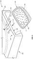
- a cooling arrangement 100 in a turbine component 101 having a surface in dissembled state is provided.
- Turbine component 101 includes an interior cooling passage (not shown) formed therein.
- Turbine component 101 further includes a hot side 110 and a cold side 109.
- Cooling arrangement 100 comprises a slot 102 formed through a sidewall 103 of turbine component 101.
- Cooling arrangement 100 further comprises a recessed insert 104 secured within slot 102.
- Insert 104 includes one or more cooling features 105 on an impingement surface 111, and a cavity 106 (pre-impingement).
- the cooling arrangement 100 further comprises at least one passage 107 in fluid communication with the internal cooling passage (not shown), insert 104, and an exterior surface 108 of turbine component 101.
- Recessed insert 104 is capable of sliding into slot 102 of turbine component 101 in a direction 113.
- FIG. 2 a partial sectional view of taken 2-2 of FIG. 1 in assembled state is provided.
- Insert 104 is secured to slot 102 of turbine 101.
- the outer contour of insert 104 is continuously and smoothly jointed to sidewall 103 of turbine component 101 so that an aerodynamic profile is maintained.
- Coolant gas path 203 flows from an internal cooling passage 201 through a high-pressure connector 202 into cavity 106 (pre-impingement). Coolant gas path 203 then impinges through one or more cooling features 105 of impingement surface 111 into another cavity 205 (post-impingement) formed between impingement surface 111 and cold side 109 comprising an inner surface 112 when assembled as shown.
- cavity 205 may not exist.
- cooling features 105 may include, but not be limited to, one or more impingement hole. In one embodiment, cooling features 105 are distributed uniformly on impingement surface 111. In another embodiment, cooling features 105 are distributed not uniformly on impingement surface 111. Coolant gas path 203 then flows outside cavity 205 through at least one passage 107. In one embodiment, passage 107 is aligned to induce maximized cooling effects. In one embodiment, coolant gas path 203 forms a cooling stream and/or film on the surface of turbine component 101, thereby protecting turbine component 101 from high temperature environments.
- sidewall 103 is a sidewall other than a slashface. In another embodiment, sidewall 103 is a slashface. In another embodiment, sidewall 103 is both a sidewall and a slashface.
- turbine component 101 includes more than one slot 102 to which more than one insert 104 is inserted or secured.
- pressure connector 202 is also directly connected to cavity 205 when assembled. In another embodiment, pressure connector 202 is connected to either cavity 205 or cavity 206 when assembled.
- insert 104 comprises a material including, but not limited to, a nickel based superalloy, a cobalt based superalloy, a titanium based super alloy, and combinations thereof.
- a person skilled in the art will appreciate other materials for insert 104.
- insert 104 is the same material as turbine component 101. In another embodiment, insert 104 is not the same material as turbine component 101.
- insert 104 is arranged and disposed to provide impingement cooling on inner surface 112 of slot 102.
- turbine component 101 includes, but not limited to, nozzle, blade, shroud, combustor liner, and combinations thereof. A person skilled in the art will appreciate other turbine components.
- Turbine component 101 includes an interior cooling passage 201 formed therein.
- Method 300 comprises a step of forming a slot 102 through a sidewall 103 of turbine component 101 (step 301).
- Method 300 further comprises a step of forming an insert 104 having one or more cooling features 105 and a cavity 106 (step 302).
- Method 300 further comprises a step of positioning insert 104 within slot 102 (step 303).
- Method 300 further comprises a step of securing insert 104 within slot 102 (step 304).
- Method 300 further comprises a step of forming at least one passage 107 in fluid communication with internal cooling passage 201, insert 104, and an exterior surface of turbine component 101(step 305).
- insert 104 is formed via an additive manufacturing process including direct metal laser melting (DMLM), direct metal laser sintering (DMLS), casting, 3D printing, fabrication, and combinations thereof.
- DMLM direct metal laser melting
- DMLS direct metal laser sintering
- casting 3D printing
- fabrication fabrication, and combinations thereof.
- insert 104 is secured to sidewall 103 via a process selected from the group consisting of mechanical joining, welding, and combinations thereof.
Landscapes
- Engineering & Computer Science (AREA)
- Mechanical Engineering (AREA)
- General Engineering & Computer Science (AREA)
- Chemical & Material Sciences (AREA)
- Manufacturing & Machinery (AREA)
- Materials Engineering (AREA)
- Physics & Mathematics (AREA)
- Plasma & Fusion (AREA)
- Combustion & Propulsion (AREA)
- Optics & Photonics (AREA)
- Architecture (AREA)
- Fluid Mechanics (AREA)
- Turbine Rotor Nozzle Sealing (AREA)
Abstract
Description
- The present invention is generally directed to a cooling arrangement and a method of creating a cooling arrangement. More specifically, the present invention is directed to a cooling arrangement in a turbine component and a method of creating a cooling arrangement for a turbine component.
- Certain components, such as gas turbine components operate at high temperatures and under harsh conditions. Cooling passages may be formed in gas turbine components to help circulate coolant for extending the service life of these components. However, incorporating cooling passages, such as by casting, is expensive.
- In an exemplary embodiment, a method of creating a cooling arrangement for a turbine component having a surface is provided. The turbine component includes an interior cooling passage formed therein. The method comprises a step of forming a slot through a sidewall of the turbine component. The method further comprises a step of forming an insert having one or more cooling features, and a cavity. The method further comprises a step of positioning the insert within the slot. The method further comprises a step of securing the insert within the slot. The method further comprises a step of forming at least one passage in fluid communication with the internal cooling passage, the insert, and an exterior surface of the turbine component.
- In another exemplary embodiment, a cooling arrangement in a turbine component having a surface is provided. The turbine component includes an interior cooling passage formed therein. The cooling arrangement comprises a slot formed through a sidewall of the turbine component. The cooling arrangement further comprises an insert secured within the slot. The insert has one or more cooling features, and a cavity. The cooling arrangement further comprises at least one passage in fluid communication with the internal cooling passage, the insert, and an exterior surface of the turbine component.
- Other features and advantages of the present invention will be apparent from the following more detailed description of the preferred embodiment, taken in conjunction with the accompanying drawings, which illustrate, by way of example, the principles of the invention.
-
-
FIG. 1 illustrates a perspective view of a turbine component and an insert in disassembled state according to an exemplary embodiment of the present disclosure. -
FIG. 2 illustrates a partial sectional view of taken 2-2 ofFIG. 1 in assembled state according to an exemplary embodiment of the present disclosure. -
FIG. 3 illustrates a method according to an exemplary embodiment of the present disclosure. - Wherever possible, the same reference numbers will be used throughout the drawings to represent the same parts.
- The detailed description set forth below in connection with the appended drawings where like numerals reference like elements is intended as a description of various embodiments of the disclosed subject matter and is not intended to represent the only embodiments. Each embodiment described in this disclosure is provided merely as an example or illustration and should not be construed as preferred or advantageous over other embodiments. The illustrative examples provided herein are not intended to be exhaustive or to limit the claimed subject matter to the precise forms disclosed.
- Provided are exemplary methods and platform cooling arrangements. Embodiments of the present disclosure, in comparison to methods and platform cooling arrangements not utilizing one or more features disclosed herein, enable lower cost, increased heat transfer coefficients, higher engine performance and less cooling flow by allowing more complicated interior geometries.
- All numbers expressing quantities of ingredients and/or reaction conditions are to be understood as being modified in all instances by the term "about", unless otherwise indicated.
- All percentages and ratios are calculated by weight unless otherwise indicated. All percentages are calculated based on the total weight of a composition unless otherwise indicated. All component or composition levels are in reference to the active level of that component or composition, and are exclusive of impurities, for example, residual solvents or by-products, which may be present in commercially available sources.
- The articles "a" and "an," as used herein, mean one or more when applied to any feature in embodiments of the present invention described in the specification and claims. The use of "a" and "an" does not limit the meaning to a single feature unless such a limit is specifically stated. The article "the" preceding singular or plural nouns or noun phrases denotes a particular specified feature or particular specified features and may have a singular or plural connotation depending upon the context in which it is used. The adjective "any" means one, some, or all indiscriminately of whatever quantity.
- The term "at least one," as used herein, means one or more and thus includes individual components as well as mixtures/combinations.
- The term "comprising" (and its grammatical variations), as used herein, is used in the inclusive sense of "having" or "including" and not in the exclusive sense of "consisting only of."
- With reference to
FIG. 1 , acooling arrangement 100 in aturbine component 101 having a surface in dissembled state is provided.Turbine component 101 includes an interior cooling passage (not shown) formed therein.Turbine component 101 further includes ahot side 110 and acold side 109.Cooling arrangement 100 comprises aslot 102 formed through asidewall 103 ofturbine component 101.Cooling arrangement 100 further comprises arecessed insert 104 secured withinslot 102. Insert 104 includes one or more cooling features 105 on animpingement surface 111, and a cavity 106 (pre-impingement). Thecooling arrangement 100 further comprises at least onepassage 107 in fluid communication with the internal cooling passage (not shown),insert 104, and anexterior surface 108 ofturbine component 101. Recessedinsert 104 is capable of sliding intoslot 102 ofturbine component 101 in adirection 113. - With reference to
FIG. 2 , a partial sectional view of taken 2-2 ofFIG. 1 in assembled state is provided. Insert 104 is secured toslot 102 ofturbine 101. The outer contour ofinsert 104 is continuously and smoothly jointed tosidewall 103 ofturbine component 101 so that an aerodynamic profile is maintained.Coolant gas path 203 flows from aninternal cooling passage 201 through a high-pressure connector 202 into cavity 106 (pre-impingement).Coolant gas path 203 then impinges through one or more cooling features 105 ofimpingement surface 111 into another cavity 205 (post-impingement) formed betweenimpingement surface 111 andcold side 109 comprising an inner surface 112 when assembled as shown. When disassembled,cavity 205 may not exist. In one embodiment,cooling features 105 may include, but not be limited to, one or more impingement hole. In one embodiment,cooling features 105 are distributed uniformly onimpingement surface 111. In another embodiment,cooling features 105 are distributed not uniformly onimpingement surface 111.Coolant gas path 203 then flows outsidecavity 205 through at least onepassage 107. In one embodiment,passage 107 is aligned to induce maximized cooling effects. In one embodiment,coolant gas path 203 forms a cooling stream and/or film on the surface ofturbine component 101, thereby protectingturbine component 101 from high temperature environments. - In one embodiment,
sidewall 103 is a sidewall other than a slashface. In another embodiment,sidewall 103 is a slashface. In another embodiment,sidewall 103 is both a sidewall and a slashface. - In one embodiment,
turbine component 101 includes more than oneslot 102 to which more than oneinsert 104 is inserted or secured. - In one embodiment, pressure connector 202 is also directly connected to
cavity 205 when assembled. In another embodiment, pressure connector 202 is connected to eithercavity 205 or cavity 206 when assembled. - In one embodiment, insert 104 comprises a material including, but not limited to, a nickel based superalloy, a cobalt based superalloy, a titanium based super alloy, and combinations thereof. A person skilled in the art will appreciate other materials for
insert 104. - In one embodiment, insert 104 is the same material as
turbine component 101. In another embodiment, insert 104 is not the same material asturbine component 101. - In one embodiment, insert 104 is arranged and disposed to provide impingement cooling on inner surface 112 of
slot 102. - In one embodiment,
turbine component 101 includes, but not limited to, nozzle, blade, shroud, combustor liner, and combinations thereof. A person skilled in the art will appreciate other turbine components. - With reference to
FIG. 3 , amethod 300 of creating acooling arrangement 100 for aturbine component 101 having a surface is provided.Turbine component 101 includes aninterior cooling passage 201 formed therein.Method 300 comprises a step of forming aslot 102 through asidewall 103 of turbine component 101 (step 301).Method 300 further comprises a step of forming aninsert 104 having one or more cooling features 105 and a cavity 106 (step 302).Method 300 further comprises a step ofpositioning insert 104 within slot 102 (step 303).Method 300 further comprises a step of securinginsert 104 within slot 102 (step 304).Method 300 further comprises a step of forming at least onepassage 107 in fluid communication withinternal cooling passage 201, insert 104, and an exterior surface of turbine component 101(step 305). - In one embodiment, insert 104 is formed via an additive manufacturing process including direct metal laser melting (DMLM), direct metal laser sintering (DMLS), casting, 3D printing, fabrication, and combinations thereof. A person skilled in the art will appreciate other additive manufacturing process.
- In one embodiment, insert 104 is secured to sidewall 103 via a process selected from the group consisting of mechanical joining, welding, and combinations thereof.
- While the invention has been described with reference to a preferred embodiment, it will be understood by those skilled in the art that various changes may be made and equivalents may be substituted for elements thereof without departing from the scope of the invention. In addition, many modifications may be made to adapt a particular situation or material to the teachings of the invention without departing from the essential scope thereof. Therefore, it is intended that the invention not be limited to the particular embodiment disclosed as the best mode contemplated for carrying out this invention, but that the invention will include all embodiments falling within the scope of the appended claims.
- Various aspects and embodiments of the present invention are defined by the following numbered clauses:
- 1. A method of creating a cooling arrangement for a turbine component having a surface, wherein the turbine component includes an interior cooling passage formed therein, the method comprising steps of:
- forming a slot through a sidewall of the turbine component;
- forming an insert having one or more cooling features and a cavity;
- positioning the insert within the slot;
- securing the insert within the slot; and
- forming at least one passage in fluid communication with the internal cooling passage, the insert, and an exterior surface of the turbine component.
- 2. The method of clause 1, wherein the sidewall is a sidewall other than a slashface.
- 3. The method of
clause 1 or 2, wherein the step of forming the insert comprises an additive manufacturing process selected from the group consisting of direct metal laser melting, direct metal laser sintering, casting, 3D printing, fabrication, and combinations thereof. - 4. The method of any preceding clause, wherein the step of securing the insert within the slot comprises a process selected from the group consisting of mechanical joining, brazing, welding, and combinations thereof.
- 5. The method of any preceding clause, wherein the insert comprises a metal selected from a nickel based superalloy, a cobalt based superalloy, a titanium based super alloy, and combinations thereof.
- 6. The method of any preceding clause, wherein the insert is the same material as the turbine component.
- 7. The method of any preceding clause, wherein the insert is arranged and disposed to provide impingement cooling on an inner surface of the slot.
- 8. The method of any preceding clause, wherein the insert comprises an impingement surface, the impingement surface comprising the one or more cooling features.
- 9. The method of any preceding clause, wherein the insert is in fluid communication with an exterior surface of the turbine component through at least one passage.
- 10. The method of any preceding clause, wherein the turbine component is selected from the group consisting of nozzle, blade, shroud, combustor liner, and combinations thereof.
- 11. A cooling arrangement in a turbine component having a surface, wherein the turbine component includes an interior cooling passage formed therein, the cooling arrangement comprising:
- a slot formed through a sidewall of the turbine component;
- an insert secured within the slot, the insert having one or more cooling features and a cavity; and
- at least one passage in fluid communication with the internal cooling passage, the insert, and an exterior surface of the turbine component.
- 12. The cooling arrangement of any preceding clause, wherein the sidewall is a sidewall other than a slashface.
- 13. The cooling arrangement of any preceding clause, wherein the insert is formed via an additive manufacturing process selected from the group consisting of direct metal laser melting, direct metal laser sintering, casting, 3D printing, fabrication, and combinations thereof.
- 14. The cooling arrangement of any preceding clause, wherein the insert is secured to the sidewall via a process selected from the group consisting of mechanical joining, welding, and combinations thereof.
- 15. The cooling arrangement of any preceding clause, wherein the insert comprises a metal selected from a nickel based superalloy, a cobalt based superalloy, a titanium based super alloy, and combinations thereof.
- 16. The cooling arrangement of any preceding clause, wherein the insert is the same material as the turbine component.
- 17. The cooling arrangement of any preceding clause, wherein the insert is arranged and disposed to provide impingement cooling on an inner surface of the slot.
- 18. The cooling arrangement of any preceding clause, wherein the insert comprises an impingement surface, the impingement surface comprising the one or more cooling features.
- 19. The cooling arrangement of any preceding clause, wherein insert is in fluid communication with an exterior surface of the turbine component through at least one passage.
- 20. The cooling arrangement of any preceding clause, wherein the turbine component is selected from the group consisting of nozzle, blade, shroud, combustor liner, and combinations thereof.
Claims (15)
- A method (300) of creating a cooling arrangement (100) for a turbine component (101) having a surface, wherein the turbine component (101) includes an interior cooling passage formed therein, the method (300) comprising steps of:forming a slot (102) through a side wall of the turbine component (101);forming an insert (104) having one or more cooling features (105) and a cavity (106);positioning the insert (104) within the slot (102);securing the insert (104) within the slot (102); andforming at least one passage (107) in fluid communication with the internal cooling passage (201), the insert (104), and an exterior surface (108) of the turbine component (101).
- The method (300) of claim 1, wherein the side wall is a side wall other than a slashface.
- The method (300) of claim 1 or 2, wherein the step of forming the insert (104) comprises an additive manufacturing process selected from the group consisting of direct metal laser melting, direct metal laser sintering, casting, 3D printing, fabrication, and combinations thereof.
- The method (300) of claim 1, 2 or 3, wherein the step of securing the insert (104) within the slot (102) comprises a process selected from the group consisting of mechanical joining, brazing, welding, and combinations thereof.
- The method (300) of any preceding claim, wherein the insert (104) comprises a metal selected from a nickel based superalloy, a cobalt based superalloy, a titanium based super alloy, and combinations thereof.
- The method (300) of any preceding claim, wherein the insert (104) is arranged and disposed to provide impingement cooling on an inner surface (112) of the slot (102).
- The method (300) of any preceding claim, wherein the insert (104) comprises an impingement surface (111), the impingement surface (111) comprising the one or more cooling features (105).
- The method (300) of claim 7, wherein the insert (104) is in fluid communication with an exterior surface (108) of the turbine component (101) through at least one passage (107).
- The method (300) of any preceding claim, wherein the turbine component (101) is selected from the group consisting of nozzle, blade, shroud, combustor liner, and combinations thereof.
- A cooling arrangement (100) in a turbine component (101) having a surface, wherein the turbine component (101) includes an interior cooling passage formed therein, the cooling arrangement (100) comprising:a slot (102) formed through a sidewall (103) of the turbine component (101);an insert (104) secured within the slot (102), the insert (104) having one or more cooling features (105) and a cavity (106); andat least one passage (107) in fluid communication with the internal cooling passage (201), the insert (104), and an exterior surface (108) of the turbine component (101).
- The cooling arrangement (100) of claim 10, wherein the side wall is a side wall other than a slashface.
- The cooling arrangement (100) of claim 10 or 11, wherein the insert (104) is arranged and disposed to provide impingement cooling on an inner surface (112) of the slot (102).
- The cooling arrangement (100) of claim 10, 11 or 12 wherein the insert (104) comprises an impingement surface (111), the impingement surface (111) comprising the one or more cooling features (105).
- The cooling arrangement (100) of claim 13, wherein insert (104) is in fluid communication with an exterior surface (108) of the turbine component (101) through at least one passage (107).
- The cooling arrangement (100) of any of claims 10 to 14, wherein the turbine component (101) is selected from the group consisting of nozzle, blade, shroud, combustor liner, and combinations thereof.
Applications Claiming Priority (1)
| Application Number | Priority Date | Filing Date | Title |
|---|---|---|---|
| US15/621,394 US20180355725A1 (en) | 2017-06-13 | 2017-06-13 | Platform cooling arrangement in a turbine component and a method of creating a platform cooling arrangement |
Publications (2)
| Publication Number | Publication Date |
|---|---|
| EP3421165A1 true EP3421165A1 (en) | 2019-01-02 |
| EP3421165B1 EP3421165B1 (en) | 2020-07-29 |
Family
ID=62530114
Family Applications (1)
| Application Number | Title | Priority Date | Filing Date |
|---|---|---|---|
| EP18175824.4A Active EP3421165B1 (en) | 2017-06-13 | 2018-06-04 | Method of creating a cooling arrangement of a turbine component; turbine component with such cooling arrangement |
Country Status (4)
| Country | Link |
|---|---|
| US (1) | US20180355725A1 (en) |
| EP (1) | EP3421165B1 (en) |
| JP (1) | JP2019023465A (en) |
| CN (1) | CN109083685B (en) |
Citations (4)
| Publication number | Priority date | Publication date | Assignee | Title |
|---|---|---|---|---|
| US20120082565A1 (en) * | 2010-09-30 | 2012-04-05 | General Electric Company | Apparatus and methods for cooling platform regions of turbine rotor blades |
| US20120134845A1 (en) * | 2010-11-29 | 2012-05-31 | Alexander Anatolievich Khanin | Blade for a gas turbine, method for manufacturing a turbine blade, and gas turbine with a blade |
| EP2728114A1 (en) * | 2012-10-31 | 2014-05-07 | Siemens Aktiengesellschaft | A platform cooling device for a blade of a turbomachine and a blade for a turbomachine |
| US20160177782A1 (en) * | 2013-08-05 | 2016-06-23 | United Technologies Corporation | Engine component having platform with passageway |
Family Cites Families (11)
| Publication number | Priority date | Publication date | Assignee | Title |
|---|---|---|---|---|
| JPS6363504U (en) * | 1986-10-15 | 1988-04-26 | ||
| JP3546135B2 (en) * | 1998-02-23 | 2004-07-21 | 三菱重工業株式会社 | Gas turbine blade platform |
| US6478540B2 (en) * | 2000-12-19 | 2002-11-12 | General Electric Company | Bucket platform cooling scheme and related method |
| EP1566519A1 (en) * | 2004-02-23 | 2005-08-24 | Siemens Aktiengesellschaft | High temperature resisting component for a fluidic machine and fluidic machine using this component. |
| US8109725B2 (en) * | 2008-12-15 | 2012-02-07 | United Technologies Corporation | Airfoil with wrapped leading edge cooling passage |
| US20100239409A1 (en) * | 2009-03-18 | 2010-09-23 | General Electric Company | Method of Using and Reconstructing a Film-Cooling Augmentation Device for a Turbine Airfoil |
| JP2011043118A (en) * | 2009-08-21 | 2011-03-03 | Ihi Corp | Cooling structure for turbine, and turbine |
| US8840369B2 (en) * | 2010-09-30 | 2014-09-23 | General Electric Company | Apparatus and methods for cooling platform regions of turbine rotor blades |
| US8684664B2 (en) * | 2010-09-30 | 2014-04-01 | General Electric Company | Apparatus and methods for cooling platform regions of turbine rotor blades |
| US8851845B2 (en) * | 2010-11-17 | 2014-10-07 | General Electric Company | Turbomachine vane and method of cooling a turbomachine vane |
| US9011079B2 (en) * | 2012-01-09 | 2015-04-21 | General Electric Company | Turbine nozzle compartmentalized cooling system |
-
2017
- 2017-06-13 US US15/621,394 patent/US20180355725A1/en not_active Abandoned
-
2018
- 2018-06-04 EP EP18175824.4A patent/EP3421165B1/en active Active
- 2018-06-08 JP JP2018109920A patent/JP2019023465A/en active Pending
- 2018-06-13 CN CN201810606966.8A patent/CN109083685B/en active Active
Patent Citations (4)
| Publication number | Priority date | Publication date | Assignee | Title |
|---|---|---|---|---|
| US20120082565A1 (en) * | 2010-09-30 | 2012-04-05 | General Electric Company | Apparatus and methods for cooling platform regions of turbine rotor blades |
| US20120134845A1 (en) * | 2010-11-29 | 2012-05-31 | Alexander Anatolievich Khanin | Blade for a gas turbine, method for manufacturing a turbine blade, and gas turbine with a blade |
| EP2728114A1 (en) * | 2012-10-31 | 2014-05-07 | Siemens Aktiengesellschaft | A platform cooling device for a blade of a turbomachine and a blade for a turbomachine |
| US20160177782A1 (en) * | 2013-08-05 | 2016-06-23 | United Technologies Corporation | Engine component having platform with passageway |
Also Published As
| Publication number | Publication date |
|---|---|
| CN109083685A (en) | 2018-12-25 |
| JP2019023465A (en) | 2019-02-14 |
| CN109083685B (en) | 2023-08-29 |
| US20180355725A1 (en) | 2018-12-13 |
| EP3421165B1 (en) | 2020-07-29 |
Similar Documents
| Publication | Publication Date | Title |
|---|---|---|
| US10619499B2 (en) | Component and method for forming a component | |
| CN102434287B (en) | There is component and the manufacture method thereof of membrane type Cooling Holes | |
| CN105378226B (en) | Turbine nozzle with impact baffle plate | |
| US6186741B1 (en) | Airfoil component having internal cooling and method of cooling | |
| US7448850B2 (en) | Closed loop, steam cooled turbine shroud | |
| EP2607624B1 (en) | Vane for a turbomachine | |
| EP3385621B1 (en) | Combustor panel cooling | |
| US10415394B2 (en) | Gas turbine engine blade with ceramic tip and cooling arrangement | |
| JP6400697B2 (en) | Gas turbine engine with liquid metal cooling | |
| EP3074606B1 (en) | Gas turbine engine airfoil with leading edge trench and impingement cooling | |
| CA2958049C (en) | Encapsulated cooling for turbine shrouds | |
| US8096751B2 (en) | Turbine engine component with cooling passages | |
| EP3822455A2 (en) | Airfoil with ribs defining shaped cooling channel | |
| EP3421165A1 (en) | Method of creating a cooling arrangement of a turbine component; turbine component with such cooling arrangement | |
| CN108798802B (en) | Method for providing a cooling structure for a component | |
| EP1245788B1 (en) | Methods and apparatus for preferential placement of turbine nozzles and shrouds based on inlet conditions | |
| JP7003265B2 (en) | Brazing heat transfer mechanism for cooling turbine parts | |
| EP2971582B1 (en) | Retention pin and method of forming | |
| US9109447B2 (en) | Combustion system including a transition piece and method of forming using a cast superalloy | |
| US10830072B2 (en) | Turbomachine airfoil | |
| EP2592226B1 (en) | Turbomachine component and method of connecting cooling circuits of a turbomacine component | |
| GB2518335A (en) | Vane for a gas turbine engine |
Legal Events
| Date | Code | Title | Description |
|---|---|---|---|
| PUAI | Public reference made under article 153(3) epc to a published international application that has entered the european phase |
Free format text: ORIGINAL CODE: 0009012 |
|
| STAA | Information on the status of an ep patent application or granted ep patent |
Free format text: STATUS: THE APPLICATION HAS BEEN PUBLISHED |
|
| AK | Designated contracting states |
Kind code of ref document: A1 Designated state(s): AL AT BE BG CH CY CZ DE DK EE ES FI FR GB GR HR HU IE IS IT LI LT LU LV MC MK MT NL NO PL PT RO RS SE SI SK SM TR |
|
| AX | Request for extension of the european patent |
Extension state: BA ME |
|
| STAA | Information on the status of an ep patent application or granted ep patent |
Free format text: STATUS: REQUEST FOR EXAMINATION WAS MADE |
|
| 17P | Request for examination filed |
Effective date: 20190702 |
|
| RBV | Designated contracting states (corrected) |
Designated state(s): AL AT BE BG CH CY CZ DE DK EE ES FI FR GB GR HR HU IE IS IT LI LT LU LV MC MK MT NL NO PL PT RO RS SE SI SK SM TR |
|
| RIC1 | Information provided on ipc code assigned before grant |
Ipc: B23K 26/342 20140101ALI20191121BHEP Ipc: F01D 25/08 20060101ALI20191121BHEP Ipc: B23K 103/18 20060101ALN20191121BHEP Ipc: F01D 5/18 20060101ALI20191121BHEP Ipc: F01D 9/02 20060101ALI20191121BHEP Ipc: B23K 31/02 20060101ALI20191121BHEP Ipc: B23K 101/00 20060101ALN20191121BHEP Ipc: B23K 1/00 20060101AFI20191121BHEP |
|
| RIC1 | Information provided on ipc code assigned before grant |
Ipc: B23K 101/00 20060101ALN20191127BHEP Ipc: B23K 31/02 20060101ALI20191127BHEP Ipc: F01D 5/18 20060101ALI20191127BHEP Ipc: B23K 26/342 20140101ALI20191127BHEP Ipc: F01D 9/02 20060101ALI20191127BHEP Ipc: B23K 103/18 20060101ALN20191127BHEP Ipc: F01D 25/08 20060101ALI20191127BHEP Ipc: B23K 1/00 20060101AFI20191127BHEP |
|
| RIC1 | Information provided on ipc code assigned before grant |
Ipc: F01D 9/02 20060101ALI20191206BHEP Ipc: B23K 103/18 20060101ALN20191206BHEP Ipc: B23K 26/342 20140101ALI20191206BHEP Ipc: F01D 25/08 20060101ALI20191206BHEP Ipc: B23K 1/00 20060101AFI20191206BHEP Ipc: B23K 31/02 20060101ALI20191206BHEP Ipc: B23K 101/00 20060101ALN20191206BHEP Ipc: F01D 5/18 20060101ALI20191206BHEP |
|
| GRAP | Despatch of communication of intention to grant a patent |
Free format text: ORIGINAL CODE: EPIDOSNIGR1 |
|
| STAA | Information on the status of an ep patent application or granted ep patent |
Free format text: STATUS: GRANT OF PATENT IS INTENDED |
|
| INTG | Intention to grant announced |
Effective date: 20200117 |
|
| GRAS | Grant fee paid |
Free format text: ORIGINAL CODE: EPIDOSNIGR3 |
|
| GRAA | (expected) grant |
Free format text: ORIGINAL CODE: 0009210 |
|
| STAA | Information on the status of an ep patent application or granted ep patent |
Free format text: STATUS: THE PATENT HAS BEEN GRANTED |
|
| AK | Designated contracting states |
Kind code of ref document: B1 Designated state(s): AL AT BE BG CH CY CZ DE DK EE ES FI FR GB GR HR HU IE IS IT LI LT LU LV MC MK MT NL NO PL PT RO RS SE SI SK SM TR |
|
| REG | Reference to a national code |
Ref country code: CH Ref legal event code: EP |
|
| REG | Reference to a national code |
Ref country code: DE Ref legal event code: R096 Ref document number: 602018006370 Country of ref document: DE |
|
| REG | Reference to a national code |
Ref country code: AT Ref legal event code: REF Ref document number: 1295220 Country of ref document: AT Kind code of ref document: T Effective date: 20200815 |
|
| REG | Reference to a national code |
Ref country code: IE Ref legal event code: FG4D |
|
| REG | Reference to a national code |
Ref country code: LT Ref legal event code: MG4D |
|
| REG | Reference to a national code |
Ref country code: NL Ref legal event code: MP Effective date: 20200729 |
|
| REG | Reference to a national code |
Ref country code: AT Ref legal event code: MK05 Ref document number: 1295220 Country of ref document: AT Kind code of ref document: T Effective date: 20200729 |
|
| PG25 | Lapsed in a contracting state [announced via postgrant information from national office to epo] |
Ref country code: NO Free format text: LAPSE BECAUSE OF FAILURE TO SUBMIT A TRANSLATION OF THE DESCRIPTION OR TO PAY THE FEE WITHIN THE PRESCRIBED TIME-LIMIT Effective date: 20201029 Ref country code: ES Free format text: LAPSE BECAUSE OF FAILURE TO SUBMIT A TRANSLATION OF THE DESCRIPTION OR TO PAY THE FEE WITHIN THE PRESCRIBED TIME-LIMIT Effective date: 20200729 Ref country code: AT Free format text: LAPSE BECAUSE OF FAILURE TO SUBMIT A TRANSLATION OF THE DESCRIPTION OR TO PAY THE FEE WITHIN THE PRESCRIBED TIME-LIMIT Effective date: 20200729 Ref country code: SE Free format text: LAPSE BECAUSE OF FAILURE TO SUBMIT A TRANSLATION OF THE DESCRIPTION OR TO PAY THE FEE WITHIN THE PRESCRIBED TIME-LIMIT Effective date: 20200729 Ref country code: PT Free format text: LAPSE BECAUSE OF FAILURE TO SUBMIT A TRANSLATION OF THE DESCRIPTION OR TO PAY THE FEE WITHIN THE PRESCRIBED TIME-LIMIT Effective date: 20201130 Ref country code: FI Free format text: LAPSE BECAUSE OF FAILURE TO SUBMIT A TRANSLATION OF THE DESCRIPTION OR TO PAY THE FEE WITHIN THE PRESCRIBED TIME-LIMIT Effective date: 20200729 Ref country code: HR Free format text: LAPSE BECAUSE OF FAILURE TO SUBMIT A TRANSLATION OF THE DESCRIPTION OR TO PAY THE FEE WITHIN THE PRESCRIBED TIME-LIMIT Effective date: 20200729 Ref country code: LT Free format text: LAPSE BECAUSE OF FAILURE TO SUBMIT A TRANSLATION OF THE DESCRIPTION OR TO PAY THE FEE WITHIN THE PRESCRIBED TIME-LIMIT Effective date: 20200729 Ref country code: BG Free format text: LAPSE BECAUSE OF FAILURE TO SUBMIT A TRANSLATION OF THE DESCRIPTION OR TO PAY THE FEE WITHIN THE PRESCRIBED TIME-LIMIT Effective date: 20201029 Ref country code: GR Free format text: LAPSE BECAUSE OF FAILURE TO SUBMIT A TRANSLATION OF THE DESCRIPTION OR TO PAY THE FEE WITHIN THE PRESCRIBED TIME-LIMIT Effective date: 20201030 |
|
| PG25 | Lapsed in a contracting state [announced via postgrant information from national office to epo] |
Ref country code: LV Free format text: LAPSE BECAUSE OF FAILURE TO SUBMIT A TRANSLATION OF THE DESCRIPTION OR TO PAY THE FEE WITHIN THE PRESCRIBED TIME-LIMIT Effective date: 20200729 Ref country code: PL Free format text: LAPSE BECAUSE OF FAILURE TO SUBMIT A TRANSLATION OF THE DESCRIPTION OR TO PAY THE FEE WITHIN THE PRESCRIBED TIME-LIMIT Effective date: 20200729 Ref country code: RS Free format text: LAPSE BECAUSE OF FAILURE TO SUBMIT A TRANSLATION OF THE DESCRIPTION OR TO PAY THE FEE WITHIN THE PRESCRIBED TIME-LIMIT Effective date: 20200729 Ref country code: IS Free format text: LAPSE BECAUSE OF FAILURE TO SUBMIT A TRANSLATION OF THE DESCRIPTION OR TO PAY THE FEE WITHIN THE PRESCRIBED TIME-LIMIT Effective date: 20201129 |
|
| PG25 | Lapsed in a contracting state [announced via postgrant information from national office to epo] |
Ref country code: NL Free format text: LAPSE BECAUSE OF FAILURE TO SUBMIT A TRANSLATION OF THE DESCRIPTION OR TO PAY THE FEE WITHIN THE PRESCRIBED TIME-LIMIT Effective date: 20200729 |
|
| PG25 | Lapsed in a contracting state [announced via postgrant information from national office to epo] |
Ref country code: IT Free format text: LAPSE BECAUSE OF FAILURE TO SUBMIT A TRANSLATION OF THE DESCRIPTION OR TO PAY THE FEE WITHIN THE PRESCRIBED TIME-LIMIT Effective date: 20200729 Ref country code: SM Free format text: LAPSE BECAUSE OF FAILURE TO SUBMIT A TRANSLATION OF THE DESCRIPTION OR TO PAY THE FEE WITHIN THE PRESCRIBED TIME-LIMIT Effective date: 20200729 Ref country code: EE Free format text: LAPSE BECAUSE OF FAILURE TO SUBMIT A TRANSLATION OF THE DESCRIPTION OR TO PAY THE FEE WITHIN THE PRESCRIBED TIME-LIMIT Effective date: 20200729 Ref country code: RO Free format text: LAPSE BECAUSE OF FAILURE TO SUBMIT A TRANSLATION OF THE DESCRIPTION OR TO PAY THE FEE WITHIN THE PRESCRIBED TIME-LIMIT Effective date: 20200729 Ref country code: CZ Free format text: LAPSE BECAUSE OF FAILURE TO SUBMIT A TRANSLATION OF THE DESCRIPTION OR TO PAY THE FEE WITHIN THE PRESCRIBED TIME-LIMIT Effective date: 20200729 Ref country code: DK Free format text: LAPSE BECAUSE OF FAILURE TO SUBMIT A TRANSLATION OF THE DESCRIPTION OR TO PAY THE FEE WITHIN THE PRESCRIBED TIME-LIMIT Effective date: 20200729 |
|
| REG | Reference to a national code |
Ref country code: DE Ref legal event code: R097 Ref document number: 602018006370 Country of ref document: DE |
|
| PG25 | Lapsed in a contracting state [announced via postgrant information from national office to epo] |
Ref country code: AL Free format text: LAPSE BECAUSE OF FAILURE TO SUBMIT A TRANSLATION OF THE DESCRIPTION OR TO PAY THE FEE WITHIN THE PRESCRIBED TIME-LIMIT Effective date: 20200729 |
|
| PLBE | No opposition filed within time limit |
Free format text: ORIGINAL CODE: 0009261 |
|
| STAA | Information on the status of an ep patent application or granted ep patent |
Free format text: STATUS: NO OPPOSITION FILED WITHIN TIME LIMIT |
|
| PG25 | Lapsed in a contracting state [announced via postgrant information from national office to epo] |
Ref country code: SK Free format text: LAPSE BECAUSE OF FAILURE TO SUBMIT A TRANSLATION OF THE DESCRIPTION OR TO PAY THE FEE WITHIN THE PRESCRIBED TIME-LIMIT Effective date: 20200729 |
|
| 26N | No opposition filed |
Effective date: 20210430 |
|
| PG25 | Lapsed in a contracting state [announced via postgrant information from national office to epo] |
Ref country code: SI Free format text: LAPSE BECAUSE OF FAILURE TO SUBMIT A TRANSLATION OF THE DESCRIPTION OR TO PAY THE FEE WITHIN THE PRESCRIBED TIME-LIMIT Effective date: 20200729 |
|
| PG25 | Lapsed in a contracting state [announced via postgrant information from national office to epo] |
Ref country code: MC Free format text: LAPSE BECAUSE OF FAILURE TO SUBMIT A TRANSLATION OF THE DESCRIPTION OR TO PAY THE FEE WITHIN THE PRESCRIBED TIME-LIMIT Effective date: 20200729 |
|
| REG | Reference to a national code |
Ref country code: CH Ref legal event code: PL |
|
| REG | Reference to a national code |
Ref country code: BE Ref legal event code: MM Effective date: 20210630 |
|
| PG25 | Lapsed in a contracting state [announced via postgrant information from national office to epo] |
Ref country code: LU Free format text: LAPSE BECAUSE OF NON-PAYMENT OF DUE FEES Effective date: 20210604 |
|
| PG25 | Lapsed in a contracting state [announced via postgrant information from national office to epo] |
Ref country code: LI Free format text: LAPSE BECAUSE OF NON-PAYMENT OF DUE FEES Effective date: 20210630 Ref country code: IE Free format text: LAPSE BECAUSE OF NON-PAYMENT OF DUE FEES Effective date: 20210604 Ref country code: CH Free format text: LAPSE BECAUSE OF NON-PAYMENT OF DUE FEES Effective date: 20210630 |
|
| PG25 | Lapsed in a contracting state [announced via postgrant information from national office to epo] |
Ref country code: FR Free format text: LAPSE BECAUSE OF NON-PAYMENT OF DUE FEES Effective date: 20210630 |
|
| PG25 | Lapsed in a contracting state [announced via postgrant information from national office to epo] |
Ref country code: BE Free format text: LAPSE BECAUSE OF NON-PAYMENT OF DUE FEES Effective date: 20210630 |
|
| GBPC | Gb: european patent ceased through non-payment of renewal fee |
Effective date: 20220604 |
|
| PG25 | Lapsed in a contracting state [announced via postgrant information from national office to epo] |
Ref country code: GB Free format text: LAPSE BECAUSE OF NON-PAYMENT OF DUE FEES Effective date: 20220604 |
|
| PG25 | Lapsed in a contracting state [announced via postgrant information from national office to epo] |
Ref country code: CY Free format text: LAPSE BECAUSE OF FAILURE TO SUBMIT A TRANSLATION OF THE DESCRIPTION OR TO PAY THE FEE WITHIN THE PRESCRIBED TIME-LIMIT Effective date: 20200729 |
|
| PG25 | Lapsed in a contracting state [announced via postgrant information from national office to epo] |
Ref country code: HU Free format text: LAPSE BECAUSE OF FAILURE TO SUBMIT A TRANSLATION OF THE DESCRIPTION OR TO PAY THE FEE WITHIN THE PRESCRIBED TIME-LIMIT; INVALID AB INITIO Effective date: 20180604 |
|
| REG | Reference to a national code |
Ref country code: DE Ref legal event code: R081 Ref document number: 602018006370 Country of ref document: DE Owner name: GENERAL ELECTRIC TECHNOLOGY GMBH, CH Free format text: FORMER OWNER: GENERAL ELECTRIC COMPANY, SCHENECTADY, NY, US |
|
| PG25 | Lapsed in a contracting state [announced via postgrant information from national office to epo] |
Ref country code: MK Free format text: LAPSE BECAUSE OF FAILURE TO SUBMIT A TRANSLATION OF THE DESCRIPTION OR TO PAY THE FEE WITHIN THE PRESCRIBED TIME-LIMIT Effective date: 20200729 |
|
| PG25 | Lapsed in a contracting state [announced via postgrant information from national office to epo] |
Ref country code: TR Free format text: LAPSE BECAUSE OF FAILURE TO SUBMIT A TRANSLATION OF THE DESCRIPTION OR TO PAY THE FEE WITHIN THE PRESCRIBED TIME-LIMIT Effective date: 20200729 |
|
| PG25 | Lapsed in a contracting state [announced via postgrant information from national office to epo] |
Ref country code: MT Free format text: LAPSE BECAUSE OF FAILURE TO SUBMIT A TRANSLATION OF THE DESCRIPTION OR TO PAY THE FEE WITHIN THE PRESCRIBED TIME-LIMIT Effective date: 20200729 |
|
| PGFP | Annual fee paid to national office [announced via postgrant information from national office to epo] |
Ref country code: DE Payment date: 20250520 Year of fee payment: 8 |