EP3421099B1 - Breathing apparatus for an aircrew member - Google Patents
Breathing apparatus for an aircrew member Download PDFInfo
- Publication number
- EP3421099B1 EP3421099B1 EP18188055.0A EP18188055A EP3421099B1 EP 3421099 B1 EP3421099 B1 EP 3421099B1 EP 18188055 A EP18188055 A EP 18188055A EP 3421099 B1 EP3421099 B1 EP 3421099B1
- Authority
- EP
- European Patent Office
- Prior art keywords
- breathing apparatus
- altitude
- air
- cabin
- sealing element
- Prior art date
- Legal status (The legal status is an assumption and is not a legal conclusion. Google has not performed a legal analysis and makes no representation as to the accuracy of the status listed.)
- Expired - Lifetime
Links
Images



Classifications
-
- A—HUMAN NECESSITIES
- A62—LIFE-SAVING; FIRE-FIGHTING
- A62B—DEVICES, APPARATUS OR METHODS FOR LIFE-SAVING
- A62B7/00—Respiratory apparatus
- A62B7/14—Respiratory apparatus for high-altitude aircraft
-
- A—HUMAN NECESSITIES
- A62—LIFE-SAVING; FIRE-FIGHTING
- A62B—DEVICES, APPARATUS OR METHODS FOR LIFE-SAVING
- A62B7/00—Respiratory apparatus
- A62B7/02—Respiratory apparatus with compressed oxygen or air
- A62B7/04—Respiratory apparatus with compressed oxygen or air and lung-controlled oxygen or air valves
-
- A—HUMAN NECESSITIES
- A62—LIFE-SAVING; FIRE-FIGHTING
- A62B—DEVICES, APPARATUS OR METHODS FOR LIFE-SAVING
- A62B9/00—Component parts for respiratory or breathing apparatus
- A62B9/02—Valves
- A62B9/022—Breathing demand regulators
Definitions
- the present invention relates to breathing apparatus for protecting crew members, in particular the technical flight crew, of an airplane against the risks associated with depressurization at high altitude and/or the occurrence of smoke in the cockpit.
- the invention relates to a breathing apparatus for providing a respiratory gas to a crew member in a cabin of an aircraft.
- Such a breathing apparatus generally comprises:
- the breathing apparatuses are supplied, at the inlet level, with additional gas delivered by pressurized oxygen cylinders, chemical generators, or OnBoard Oxygen Generator System (OBOGS) or more generally any sources of oxygen.
- OOGS OnBoard Oxygen Generator System
- the known breathing apparatuses may generally comprise a mask and a regulator for regulating the supply in respiratory gas.
- Such breathing apparatuses are known for example from patent applications US2003/084901 , FR 2,781,381 or FR 2,827,179 which disclose breathing apparatuses in accordance with the preamble of claim 1 and describe a breathing mask provided with a demand regulator.
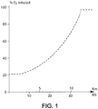
- the known regulators deliver a respiratory gas for which the oxygen enrichment must always be greater than the minimum physiologically required enrichment that depends upon the aircraft cabin altitude, as seen in dashed-line curve in FIG. 1 .
- cabin altitude one must understand the altitude corresponding to the pressurized atmosphere maintained within the cabin, thus the cabin altitude is equivalent to the cabin pressure. This value is different than the aircraft altitude which is its actual physical altitude.
- said regulator is capable of administrating the required respiratory gas volume according to the wearer's demand.
- the control is thus function of his/her respiratory demand which may be determined by the depression consecutive to the inhalation, by the volume or flowrate of the inhaled gas, by the change in thoracic cage volume, or any suitable data representative of the wearer's demand.
- the respiratory demand is nil, so is the breathable flowrate at the same moment. Beyond a respiratory demand threshold, additional gas is admitted into the demand regulator.
- known demand regulators are generally equipped with a "normal/100%" switch that closes the ambient air admission means when moved to the 100% position. This position allows the wearer of the mask to breath only highly oxygen enriched air, or pure oxygen provided thanks to the respiratory gas.
- regulators such as a continuous flowrate regulator.
- the additional gas i.e. oxygen
- an anti-suffocatory air intake is provided downstream the additional gas inlet that opens and let ambient air in upon reaching a given depression in the regulator.
- the respiratory gas comprising ambient air and/or the additional gas is supplied to the mask as a function of the cabin altitude.
- the need in oxygen might not correspond to the one given in FIG. 1 . Indeed the actual physiological needs of a crew member to ensure his safety require feeding him with pure oxygen beyond a given altitude. In other instances, for lower altitudes, it may also be interesting to feed the crewmember with ambient air as its content in oxygen is sufficient to ensure the wearer's needs.
- the known regulators are robust and reliable, and can be made in a relatively simple matter.
- the security margins taken for their dimensioning lead to the result that over a major portion of their operating range, they draw pure oxygen at the rate that is well above the rate that is absolutely necessary.
- the consequences are direct in terms of onboard volume of oxygen that the aircraft needs to carry in excess of real physiological needs, or else it requires the presence of oxygen sources of performances and volumes that are higher than absolutely essential.
- safety regulations do require a preventive wearing of the mask by at least one pilot when the aircraft is flying beyond a given altitude. Nevertheless it is not essential up until a second given altitude that the mask is fed with oxygen.
- An object of the present invention is to provide a breathing apparatus that does not present the drawbacks from the known apparatuses.
- a further object of this invention is to make available a breathing apparatus with which it is possible to reduce the supply in additional gas while still respecting the aviation regulations.
- a breathing apparatus as the known breathing apparatuses, and further comprising neutralizing means for neutralizing at least partially the admission of the additional gas below a predefined cabin altitude, as claimed in particular in claim 1.
- the neutralization means As long as the cabin is maintained pressurized, the wearer only breathes in ambient air whose content in oxygen is sufficient. The oxygen reserves are not solicited. In case a sudden pressure drop in the cabin due to the depressurization accident, the neutralization means are deactivated and additional gas is fed to the apparatus, so that a mixture of additional gas and ambient air, if not solely additional gas, is fed to the crew member.
- the invention will be illustrated here after for breathing apparatuses comprising a demand regulator or a continuous flowrate regulator.
- the invention remains suitable for any other types of breathing apparatuses.
- FIG. 2 A known breathing apparatus with a mask and a demand regulator is illustrated in FIG. 2 .
- the regulator 1 comprises a regulator body and a "normal/100%" switch 3, shown in FIG. 2 at position "100%" (air admission closed off).
- the regulator body is made up of several parts joined together and defining a circuit for fluids. It comprises several fluid communications with the outside of the regulator body: a connector piece 27 or inlet for supply/admission of additional gas, a tubing 4 connecting with the inside of a respiratory mask (not shown), an ambient air inlet 5, a passage 36 to the atmosphere, and an exhaled gases outlet 7. It also comprises an inlet 8 in communication with the additional gas supply, here pure oxygen O 2 .
- the regulator body additionally comprises several internal fluid communications: a primary conduit 9 comprising a calibrated constriction 22, and a secondary conduit 10 connecting compartments separated by a main flap valve 11 to a compartment 21 corresponding to a pilot flap valve 12.
- the regulator body also comprises several switching members for modifying the circulation of the fluids in the circuit defined by the regulator body. These switching members are the main flap valve 11 and the pilot flap valve 12; the regulator shown has in addition a valve 13 for connecting the compartment 21 of the pilot flap valve 12 to the atmosphere, and an altimetric capsule 14 provided within mixing chamber 145.
- the mixing chamber 145 is in fluid communication with connection tubing 4.
- the flap valves are of classical configuration.
- the main flap valve 11 is formed by a membrane 15 cooperating with a fixed seat 16.
- the membrane 15 separates a control chamber 17 from the inlet 8, the primary conduit 9 and the mixing chamber 145 (leading to the connection tubing 4).
- the control chamber 17 is connected to the inlet 8 via a calibrated constriction 18.
- the membrane 15 When it is subjected to the inlet pressure of the additional gas, the membrane 15 is pressed against the seat 16, closes the passage of the additional gas in this seat 16 and separates the inlet 8 from the tubing 4.
- the pilot flap valve 12 comprises a membrane 19 sensitive to the pressure.
- the membrane 19 carries an obturator 20 which cooperates with a fixed seat to bring the control chamber 17 into communication with the compartment 21 delimited by the membrane 19, or by contrast to separate the chamber 17 and the compartment 21.
- the compartment 21 also communicates with the inlet 8 via the constriction 22.
- the pilot flap valve 12 also constitutes a release valve permitting escape of the exhaled gases via the outlet 7 for exhaled gases.
- the pressure prevailing in the chamber 21 is limited by the venting valve 13 which ensures that the overpressure in the chamber 21 does not exceed a predetermined value.
- the altimetric capsule 14 cuts off or authorizes i.e. pilots, through its length varying as a function of the altitude, the entry of air into the mixing chamber 145, via the ambient air inlet 5 and through an ambient air feed pipe 52 leading to said mixing chamber. At high altitude, the altimetric capsule 14 cuts the entry of ambient air so that the mask is supplied only with the additional gas originating from the inlet 8. To that effect, capsule 14 cooperates with a seat 53 provided on feed pipe 52 as it opens into chamber 145.
- the functioning of the regulator 1 is known and is therefore not detailed here. For more details regarding its functioning, reference can be made to the documents FR-A-1 557 809 and FR-A-2 781 381 .
- neutralizing means are provided in said breathing apparatus for neutralizing at least partially the admission of said additional gas below a predefined cabin altitude Z 1 .
- FIGs. 4.1 to 4.4 show examples of different scenarios of additional gas supply to the breathing apparatus according to the invention.
- the regulatory minimum oxygen intake (in percentage of the respiratory gas) is plotted as in FIG. 1 in dashed line.
- a first scenario presented in full line on FIG. 4.1 no oxygen is fed to the breathing apparatus up until the cabin altitude Z 1 is reached.
- the neutralizing means are activated and the inhaled oxygen corresponds to the oxygen present in the ambient air.
- the neutralizing means are deactivated completely, and 100% additional gas is fed to the breathing apparatus.
- the pilot(s) must return the aircraft to a lower altitude which is called the diversion altitude, lower than the cruising altitude.
- the neutralizing means are reactivated when the plane descends below Z 1 . This scenario is symmetrical with regards to Z 1 .
- a third scenario is presented in full line on FIG. 4.3 , no oxygen is fed to the breathing apparatus up until the cabin altitude Z 1 is reached.
- the neutralizing means are activated and the inhaled oxygen corresponds to the oxygen present in the ambient air.
- the neutralizing means are deactivated, and the additional gas is fed to the breathing apparatus so that at least the minimum regulatory oxygen (shown in dashed line) is supplied.
- the neutralizing means are reactivated below Z 1 .
- This scenario is symmetrical with regards to Z 1 .
- a fourth scenario alternative to the third scenario and represented in FIG. 4.4 , the neutralizing means are kept deactivated below Z 1 to ensure proper supply in oxygen to the crew members.
- This scenario is asymmetrical with regards to Z 1 , and below Z1, the percentage of inhaled oxygen is at least equal to the regulatory minimum shown in dashed line.
- the neutralization of additional gas may be a direct neutralization by stopping the supply in said additional oxygen or indirect neutralization by reducing the pressure loss of the ambient air inlet.
- the invention will be illustrated with, but not limited to, a breathing apparatus comprising a mask with a demand regulator.
- a breathing apparatus comprising a mask with a demand regulator.
- the man skilled in the art will easily transpose the teachings hereafter to other types of breathing apparatuses.
- the indirect neutralization of the additional gas supply will be first described.
- the ambient air inlet 5 along with the ambient air feed pipe 52, are called here after the air circuit.
- the neutralizing means comprises an air circuit for feeding the mixing chamber 145 with the ambient air, the pressure loss of said air circuit depending upon the cabin altitude.
- the pressure loss of the air circuit is reduced beyond the predefined cabin altitude Z 1 .
- the membrane 19, driving the demand in respiratory gas is not actuated upon inhalation of the wearer unless the depression caused by the wearer inhalation is significant. In this instance the intake of additional gas is partially neutralized.
- the pressure loss reduction may be achieved by providing an air circuit with an enlarged cross section area for lower cabin altitudes.
- the air circuit is therefore characterized by a flow area that depends upon the cabin altitude.
- the neutralizing means comprises a sealing element, illustrated in the form of a lever 70 in FIGS 3.1 and 3.2 , movable between a first position, which corresponds to a resting position, wherein the pressure loss of the air circuit is minimal and a second position wherein the pressure loss of the air circuit is maximal.
- FIGS. 3.1 and 3.2 show lever 70 is in its first position. This first position corresponds to a cabin altitude below the predefined cabin altitude Z 1 ; the section of the air circuit is maximal. Lever 70 is in its second position when the cabin altitude is beyond the predefined altitude; the section of the air circuit is then minimal.
- the percentage of inhaled gas additional gas is nil. This corresponds to the horizontal line in FIGS. 4.1 to 4.4 and the common stage to all 4 illustrated scenarios.
- the section of the air circuit is increased thanks to a second ambient air inlet 6 connected to a second ambient air feed pipe 62 that opens onto mixing chamber 145.
- a neutralizing chamber 65 is provided with a lever 70.
- Lever 70 is articulated around an axis 71 provided within said chamber 65.
- a seal 74 is providing, and facing a seat 142 provided on feed pipe 62 as it opens into neutralizing chamber 65.
- the opposite and second end of lever 70 faces a second altimetric capsule 141 provided in a recess of chamber 65.
- the neutralizing means works as follows.
- the first altimetric capsule 141 is adapted to move the lever 70 into its second position when the cabin altitude is greater than the predefined altitude Z 1 . Below Z 1 , capsule 141 length is minimal and lever 70 is in its resting position, with its first end and seal 74 away from seat 142.
- Biasing means (not shown in FIG. 3.1 ), such as a spring placed between lever 70 and axis 71, may be provided to maintain lever 70 in this position.
- the air circuit section is large enough to ensure minimal pressure loss from this circuit: only ambient air is sucked into the mask.
- the neutralizing means further neutralize, at least partially the admission of ambient air.
- Capsule 141 expands and pushes lever 70 second end so that lever moves towards seat 142 to its second position wherein seal 74 comes into contact with said seat 142.
- Lever 70 in its second position blocks any ambient air from flowing through second feed pipe 62.
- the configuration of the demand regulator is equivalent to the configuration of the known demand regulator, such as the one shown in FIG.2 .
- the first altimetric capsule 14 pilots the entry of ambient air into the regulator as a function of the cabin altitude, and the pressure loss of the air circuit is increased.
- the respiratory gas fed to the mask as seen in FIGS. 4.3 and 4.4 moves to at least point A which corresponds to the minimum oxygen intake on the regulatory curve in dashed line. If the cabin altitude increases further, the oxygen is fed according to the minimum curve in dashed line. The third and fourth scenarios are ensured.
- the pilot(s) After a depressurization accident, the pilot(s) must return the aircraft to a lower altitude i.e. the diversion altitude of the aircraft, which is lower than the cruising altitude.
- the neutralization means in order to ensure an asymmetric return, the neutralization means needs to be deactivated definitively to ensure that additional gas is fed to the mask as the aircraft descends below altitude Z 1 . Indeed, in such a descent scenario, the regulator must be fed with breathing gas to comply with the aviation regulations.
- Non return means are provided within chamber 65 so that seal 74 remains in contact with seat 142, besides altimetric capsule 141 length reducing with the altitude.
- the non return means may be a beveled nib with its inclined face facing lever 70 to its resting position, its flat face opposing the return of said lever in its resting position after the seal of feed pipe 62.
- Switch 3 is adapted to close both air inlets 5 and 6 when switched to the 100% position.
- FIG. 3.2 shows a second implementation of the breathing apparatus according to the invention.
- the section of the air circuit is increased thanks to an enlarged air inlet 5 connected to an enlarged ambient air feed pipe 52.
- a lever 70 is provided within mixing chamber 145.
- a sealing element here a lever 70, is articulated around an axis 71 provided on a first wall of said chamber 145.
- First altimetric capsule 14 is provided on a first end of lever 70, said capsule 14 facing seat 53 provided in chamber 145.
- the opposite and second end of lever 70 faces a second altimetric capsule 141 provided in chamber 145, e.g. on a second wall opposed the first wall mentioned here before.
- the neutralizing means works as follows. Below the given altitude Z 1 , capsule 141 length is minimal and lever 70 is in its first position or resting position, with its first end and first capsule 14 away from seat 53. Biasing means (not shown in FIG. 3.2 ), such as a spring placed between lever 70 and axis 71, may be provided to maintain lever 70 in this position.
- the air circuit section is large enough to ensure minimal pressure loss from this circuit: only ambient air is sucked into the mask.
- capsule 141 expands and pushes lever 70 second end towards the second position of lever 70. Capsule 14 is moved towards seat 53.
- the neutralizing means further neutralizes the admission of ambient air as follows.
- Non return means 75 are provided within chamber 145 so that lever 70 is maintained in its second position after second capsule 141 has expanded. This second position is such that the first end of lever 70 that carries capsule 14 is closer to seat 53 when compared to the resting position of lever 70, as seen in FIG. 3.2 .
- capsule 14 length also expands due to the depressurization. Depending on the aircraft altitude, capsule 14 may eventually come into contact with seat 53 and block any ambient air from flowing through feed pipe 52. With this position of lever 70, the air circuit is closed, and only the respiratory gas is fed to the regulator.
- the non return means may be a beveled nib with its inclined face facing lever 70 in its resting position, its flat face opposing the return of said lever to its resting position after the seal of feed pipe 52.
- the asymmetrical fourth scenario is thus achieved.
- lever 70 is actuated through a capsule 141, i.e. mechanical means.
- capsule 141 may be replaced by a piston, e.g. an annular piston, subjected to the pressure difference between the atmospheric pressure and the pressure that exists inside a piston chamber.
- An additional remotely-controlled valve serves to connect the piston chamber either to the atmosphere or else to the pressurized respiratory gas. The remotely-controlled valve thus serves to vary the pressure losses of the air circuit.
- a spring holds the piston in a position wherein the lever 70 is not actuated, and hence kept in its first position.
- the electrically controlled valve may be controlled through an electronic circuit that receives a reading of the cabin altitude through a pressure or altimeter sensor.
- the piston chamber is thus connected to the atmosphere when the cabin altitude is below Z 1 and connected to the respiratory gas source beyond Z 1 .
- the fourth asymmetrical scenario may be achieved through the here above piston (through maintaining its second position during the aircraft descent), the use of a piston driven by an electrically-controlled valve is particularly well suited when trying to achieve the third symmetrical supply scenario.
- the piston allows a precise and rapid change from the first to the second position of the sealing element, and a return to the first position in the absence of non return means.
- a movable sealing element may be used to modify the pressure loss of the air circuit, in place of lever 70.
- a sealing element either carries the seal 74 of the first implementation of the breathing apparatus, or capsule 14 of the second implementation of the regulator.
- the sealing element itself may be carried by an altimetric capsule similar to capsule 141 seen in FIGS. 3.1 and 3.2 (e.g. for the fourth scenario), or the piston mentioned here before (e. g. for the third and fourth scenarios). Any other suitable altimetric device characterized by a length varying according to the cabin pressure or/and the cabin altitude may be used as well.
- the sealing element is further movable between a first position as defined before wherein the pressure losses of the air circuit is minimal, and a second position wherein such pressure losses are increased.
- the sealing element comprises a piston 70.
- the third implementation is illustrated as a variation to the second implementation with the section of the air circuit increased thanks to an enlarged air inlet 5 connected to an enlarged ambient air feed pipe 52.
- An altimetric capsule 14 is used in mixing chamber 145 as with the known regulator of FIG. 2 .
- Piston 70 is subjected to the pressure difference between the atmospheric pressure and the pressure that exists inside a piston chamber 73.
- An additional electrically-controlled valve 80 (specifically a solenoid valve) is connected to chamber 73 through pipe 81 and serves to connect said piston chamber either to the atmosphere through pipe 82 or else to the pressurized respiratory gas, through pipe 83.
- the electrically-controlled valve 80 thus serves to vary the pressure losses of the air circuit.
- the electrically controlled valve may be controlled through an electronic circuit (not shown) that receives a reading of the cabin altitude through a pressure or altimeter sensor.
- the piston chamber is thus connected to the atmosphere when the cabin altitude is below Z 1 and connected to the respiratory gas source beyond Z 1 .
- the electrically controlled valve 80 and the piston chamber 73 form an altimetric device that is operable as a function of the cabin altitude.
- the teachings of the third implementation as seen in FIG. 3.3 are transposed to the breathing apparatus with the two ambient air feed pipes described with FIG. 3.1 .
- the second feed pipe is sealable thanks to a piston as the one here before movable between a resting position wherein the second feed pipe is open and a second position wherein the second feed pipe is sealed.
- Third and fourth implementations result in a breathing apparatus which allows following the symmetrical fourth scenario (by returning the sealing element to its first position) and the asymmetrical third scenario (by maintaining the sealing element in its second position).
- a breathing apparatus comprising a mask and a regulator with a single air inlet may be used.
- Such an apparatus may correspond to the illustration of FIG. 3.3 with no altimetric capsule, and a movable piston 70 arranged to seal off totally the ambient air feed pipe.
- a movable piston 70 arranged to seal off totally the ambient air feed pipe.
- the additional gas, the regulation means may pilot directly the supply in additional gas.
- a piston such as the one described here above for the third and fourth implementations may be provided along the supply line of additional gas upstream the regulator to open or seal the supply as a function of the altitude.
- the ambient air and the additional gas are mixed downstream the ambient air intake.
Landscapes
- Health & Medical Sciences (AREA)
- Pulmonology (AREA)
- General Health & Medical Sciences (AREA)
- Business, Economics & Management (AREA)
- Emergency Management (AREA)
- Respiratory Apparatuses And Protective Means (AREA)
Description
- The present invention relates to breathing apparatus for protecting crew members, in particular the technical flight crew, of an airplane against the risks associated with depressurization at high altitude and/or the occurrence of smoke in the cockpit.
- More precisely, the invention relates to a breathing apparatus for providing a respiratory gas to a crew member in a cabin of an aircraft.
- Such a breathing apparatus generally comprises:
- an air inlet for admission of ambient air in said breathing apparatus,
- an additional gas inlet for admission of additional gas in said breathing apparatus,
- an outlet nozzle for feeding said crew member with the respiratory gas comprising said ambient air and/or additional gas,
- The breathing apparatuses are supplied, at the inlet level, with additional gas delivered by pressurized oxygen cylinders, chemical generators, or OnBoard Oxygen Generator System (OBOGS) or more generally any sources of oxygen. The known breathing apparatuses may generally comprise a mask and a regulator for regulating the supply in respiratory gas.
- Such breathing apparatuses are known for example from patent applications
US2003/084901 ,FR 2,781,381 FR 2,827,179 claim 1 and describe a breathing mask provided with a demand regulator. The known regulators deliver a respiratory gas for which the oxygen enrichment must always be greater than the minimum physiologically required enrichment that depends upon the aircraft cabin altitude, as seen in dashed-line curve inFIG. 1 . By cabin altitude, one must understand the altitude corresponding to the pressurized atmosphere maintained within the cabin, thus the cabin altitude is equivalent to the cabin pressure. This value is different than the aircraft altitude which is its actual physical altitude. - In pressurized aircrafts, from a given altitude depending upon the type of aircrafts, the pressure within the cabin is maintained at a given value P, while the pressure level outside the airplane decreases with the altitude. When a pressure difference ΔP has been reached between the cabin and the outside of the aircraft, the cabin pressure is then decreased so as to decrease ΔP between the cabin and the outside of the aircraft. With a depressurization accident in an aircraft, the cabin pressure suddenly drops to the outside pressure within a matter of seconds.
- In a known demand regulator, said regulator is capable of administrating the required respiratory gas volume according to the wearer's demand. The control is thus function of his/her respiratory demand which may be determined by the depression consecutive to the inhalation, by the volume or flowrate of the inhaled gas, by the change in thoracic cage volume, or any suitable data representative of the wearer's demand.
- If the respiratory demand is nil, so is the breathable flowrate at the same moment. Beyond a respiratory demand threshold, additional gas is admitted into the demand regulator.
- In case of emergency situations, known demand regulators are generally equipped with a "normal/100%" switch that closes the ambient air admission means when moved to the 100% position. This position allows the wearer of the mask to breath only highly oxygen enriched air, or pure oxygen provided thanks to the respiratory gas.
- Other types of regulators may be used, such as a continuous flowrate regulator. In such a regulator, the additional gas, i.e. oxygen, is fed continuously to the regulator, and an anti-suffocatory air intake is provided downstream the additional gas inlet that opens and let ambient air in upon reaching a given depression in the regulator.
- Furthermore, for most regulators, the respiratory gas comprising ambient air and/or the additional gas is supplied to the mask as a function of the cabin altitude.
- In some instances, the need in oxygen might not correspond to the one given in
FIG. 1 . Indeed the actual physiological needs of a crew member to ensure his safety require feeding him with pure oxygen beyond a given altitude. In other instances, for lower altitudes, it may also be interesting to feed the crewmember with ambient air as its content in oxygen is sufficient to ensure the wearer's needs. - The known regulators, specifically the demand regulators, are robust and reliable, and can be made in a relatively simple matter. However in order to be able to comply under all operating conditions with the oxygen minimum intake as seen in
FIG.1 , the security margins taken for their dimensioning lead to the result that over a major portion of their operating range, they draw pure oxygen at the rate that is well above the rate that is absolutely necessary. The consequences are direct in terms of onboard volume of oxygen that the aircraft needs to carry in excess of real physiological needs, or else it requires the presence of oxygen sources of performances and volumes that are higher than absolutely essential. - Furthermore, safety regulations do require a preventive wearing of the mask by at least one pilot when the aircraft is flying beyond a given altitude. Nevertheless it is not essential up until a second given altitude that the mask is fed with oxygen.
- Therefore the flow of respiratory gas delivered to the regulator, and consequently the breathing apparatus, is too high relative to the requirements and is the cause of the excessive consumption of said respiratory gas.
- An object of the present invention is to provide a breathing apparatus that does not present the drawbacks from the known apparatuses. A further object of this invention is to make available a breathing apparatus with which it is possible to reduce the supply in additional gas while still respecting the aviation regulations.
- To this end, there is provided a breathing apparatus as the known breathing apparatuses, and further comprising neutralizing means for neutralizing at least partially the admission of the additional gas below a predefined cabin altitude, as claimed in particular in
claim 1. - Thanks to the neutralization means, as long as the cabin is maintained pressurized, the wearer only breathes in ambient air whose content in oxygen is sufficient. The oxygen reserves are not solicited. In case a sudden pressure drop in the cabin due to the depressurization accident, the neutralization means are deactivated and additional gas is fed to the apparatus, so that a mixture of additional gas and ambient air, if not solely additional gas, is fed to the crew member.
- The above features, and others, will be better understood on reading the following description of particular embodiments, given as non-limiting examples. The description refers to the accompanying drawing.
-
FIG. 1 is a graph plotting a typical curve for variation in oxygen minimum content as a function of the cabin altitude as required by regulations; -
FIG. 2 shows a known breathing apparatus; -
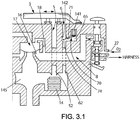
FIG. 3.1 shows a first implementation of the breathing apparatus according to the invention; -
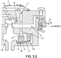
FIG. 3.2 shows a second implementation of the breathing apparatus according to the invention, -
FIG. 3.3 shows a third implementation of the breathing apparatus according to the invention; and, -
FIGS. 4.1 to 4.4 are graphs plotting exemplary scenarios of additional gas supply as a function of the cabin altitude achievable thanks to the breathing apparatus according to the invention. - The invention will be illustrated here after for breathing apparatuses comprising a demand regulator or a continuous flowrate regulator. The invention remains suitable for any other types of breathing apparatuses.
- A known breathing apparatus with a mask and a demand regulator is illustrated in
FIG. 2 . Theregulator 1 comprises a regulator body and a "normal/100%"switch 3, shown inFIG. 2 at position "100%" (air admission closed off). - The regulator body is made up of several parts joined together and defining a circuit for fluids. It comprises several fluid communications with the outside of the regulator body: a
connector piece 27 or inlet for supply/admission of additional gas, atubing 4 connecting with the inside of a respiratory mask (not shown), anambient air inlet 5, a passage 36 to the atmosphere, and an exhaled gases outlet 7. It also comprises aninlet 8 in communication with the additional gas supply, here pure oxygen O2. - The regulator body additionally comprises several internal fluid communications: a primary conduit 9 comprising a
calibrated constriction 22, and asecondary conduit 10 connecting compartments separated by a main flap valve 11 to acompartment 21 corresponding to apilot flap valve 12. - The regulator body also comprises several switching members for modifying the circulation of the fluids in the circuit defined by the regulator body. These switching members are the main flap valve 11 and the
pilot flap valve 12; the regulator shown has in addition avalve 13 for connecting thecompartment 21 of thepilot flap valve 12 to the atmosphere, and analtimetric capsule 14 provided withinmixing chamber 145. Themixing chamber 145 is in fluid communication withconnection tubing 4. - The flap valves are of classical configuration. In the case illustrated, the main flap valve 11 is formed by a
membrane 15 cooperating with a fixedseat 16. Themembrane 15 separates acontrol chamber 17 from theinlet 8, the primary conduit 9 and the mixing chamber 145 (leading to the connection tubing 4). Thecontrol chamber 17 is connected to theinlet 8 via acalibrated constriction 18. When it is subjected to the inlet pressure of the additional gas, themembrane 15 is pressed against theseat 16, closes the passage of the additional gas in thisseat 16 and separates theinlet 8 from thetubing 4. - The
pilot flap valve 12 comprises amembrane 19 sensitive to the pressure. Themembrane 19 carries anobturator 20 which cooperates with a fixed seat to bring thecontrol chamber 17 into communication with thecompartment 21 delimited by themembrane 19, or by contrast to separate thechamber 17 and thecompartment 21. Thecompartment 21 also communicates with theinlet 8 via theconstriction 22. - The
pilot flap valve 12 also constitutes a release valve permitting escape of the exhaled gases via the outlet 7 for exhaled gases. - The pressure prevailing in the
chamber 21 is limited by the ventingvalve 13 which ensures that the overpressure in thechamber 21 does not exceed a predetermined value. - The
altimetric capsule 14 cuts off or authorizes i.e. pilots, through its length varying as a function of the altitude, the entry of air into the mixingchamber 145, via theambient air inlet 5 and through an ambientair feed pipe 52 leading to said mixing chamber. At high altitude, thealtimetric capsule 14 cuts the entry of ambient air so that the mask is supplied only with the additional gas originating from theinlet 8. To that effect,capsule 14 cooperates with aseat 53 provided onfeed pipe 52 as it opens intochamber 145. - The functioning of the
regulator 1 is known and is therefore not detailed here. For more details regarding its functioning, reference can be made to the documentsFR-A-1 557 809 FR-A-2 781 381 - In the breathing apparatus according to the invention, neutralizing means are provided in said breathing apparatus for neutralizing at least partially the admission of said additional gas below a predefined cabin altitude Z1.
-
FIGs. 4.1 to 4.4 show examples of different scenarios of additional gas supply to the breathing apparatus according to the invention. The regulatory minimum oxygen intake (in percentage of the respiratory gas) is plotted as inFIG. 1 in dashed line. - In a first scenario presented in full line on
FIG. 4.1 , no oxygen is fed to the breathing apparatus up until the cabin altitude Z1 is reached. The neutralizing means are activated and the inhaled oxygen corresponds to the oxygen present in the ambient air. Beyond Z1, i.e. after a depressurization accident, the neutralizing means are deactivated completely, and 100% additional gas is fed to the breathing apparatus. After a depressurization accident, the pilot(s) must return the aircraft to a lower altitude which is called the diversion altitude, lower than the cruising altitude. In the first scenario, assuming the diversion altitude is low enough to ensure an ambient air rich enough in oxygen, the neutralizing means are reactivated when the plane descends below Z1. This scenario is symmetrical with regards to Z1. - In an alternative second scenario represented in
FIG. 4.2 , the neutralizing means are kept deactivated below Z1 to ensure proper supply in oxygen to the crew members. This scenario is asymmetrical with regards to Z1. - A third scenario is presented in full line on
FIG. 4.3 , no oxygen is fed to the breathing apparatus up until the cabin altitude Z1 is reached. The neutralizing means are activated and the inhaled oxygen corresponds to the oxygen present in the ambient air. Beyond Z1, i.e. after a depressurization accident, the neutralizing means are deactivated, and the additional gas is fed to the breathing apparatus so that at least the minimum regulatory oxygen (shown in dashed line) is supplied. As the aircraft returns to its diversion altitude (assuming the diversion altitude is low enough to ensure an ambient air rich enough in oxygen), the neutralizing means are reactivated below Z1. This scenario is symmetrical with regards to Z1. - In a fourth scenario alternative to the third scenario and represented in
FIG. 4.4 , the neutralizing means are kept deactivated below Z1 to ensure proper supply in oxygen to the crew members. This scenario is asymmetrical with regards to Z1, and below Z1, the percentage of inhaled oxygen is at least equal to the regulatory minimum shown in dashed line. - As described hereafter, the neutralization of additional gas may be a direct neutralization by stopping the supply in said additional oxygen or indirect neutralization by reducing the pressure loss of the ambient air inlet.
- In the hereafter description, the invention will be illustrated with, but not limited to, a breathing apparatus comprising a mask with a demand regulator. The man skilled in the art will easily transpose the teachings hereafter to other types of breathing apparatuses. Furthermore, the indirect neutralization of the additional gas supply will be first described.
- For simplification purposes, the
ambient air inlet 5, along with the ambientair feed pipe 52, are called here after the air circuit. - In the breathing apparatus according to the invention, the neutralizing means comprises an air circuit for feeding the mixing
chamber 145 with the ambient air, the pressure loss of said air circuit depending upon the cabin altitude. In order to neutralize the additional gas supply, the pressure loss of the air circuit is reduced beyond the predefined cabin altitude Z1. Thus themembrane 19, driving the demand in respiratory gas, is not actuated upon inhalation of the wearer unless the depression caused by the wearer inhalation is significant. In this instance the intake of additional gas is partially neutralized. - The pressure loss reduction may be achieved by providing an air circuit with an enlarged cross section area for lower cabin altitudes. The air circuit is therefore characterized by a flow area that depends upon the cabin altitude.
- To achieve such varying pressure losses of the air circuit, the neutralizing means comprises a sealing element, illustrated in the form of a
lever 70 inFIGS 3.1 and3.2 , movable between a first position, which corresponds to a resting position, wherein the pressure loss of the air circuit is minimal and a second position wherein the pressure loss of the air circuit is maximal.FIGS. 3.1 and3.2 show lever 70 is in its first position. This first position corresponds to a cabin altitude below the predefined cabin altitude Z1; the section of the air circuit is maximal.Lever 70 is in its second position when the cabin altitude is beyond the predefined altitude; the section of the air circuit is then minimal. - As the regulator is only fed with ambient air, the percentage of inhaled gas additional gas is nil. This corresponds to the horizontal line in
FIGS. 4.1 to 4.4 and the common stage to all 4 illustrated scenarios. - In the first implementation show in
FIG. 3.1 of the demand regulator according to the invention, the section of the air circuit is increased thanks to a secondambient air inlet 6 connected to a second ambientair feed pipe 62 that opens onto mixingchamber 145. With the resulting decreased pressure loss from the air circuit, only ambient air is sucked in by the mask wearer. In order to increase the pressure loss of the air circuit beyond the given altitude Z1, in case e.g. of a sudden or slow depressurization of the cabin, a neutralizingchamber 65 is provided with alever 70. -
Lever 70 is articulated around anaxis 71 provided within saidchamber 65. On a first end oflever 70, aseal 74 is providing, and facing aseat 142 provided onfeed pipe 62 as it opens into neutralizingchamber 65. The opposite and second end oflever 70 faces a secondaltimetric capsule 141 provided in a recess ofchamber 65. - In the first position of
lever 70, the pressure loss of the air circuit is minimal. - The neutralizing means works as follows. The first
altimetric capsule 141 is adapted to move thelever 70 into its second position when the cabin altitude is greater than the predefined altitude Z1. Below Z1,capsule 141 length is minimal andlever 70 is in its resting position, with its first end and seal 74 away fromseat 142. Biasing means (not shown inFIG. 3.1 ), such as a spring placed betweenlever 70 andaxis 71, may be provided to maintainlever 70 in this position. The air circuit section is large enough to ensure minimal pressure loss from this circuit: only ambient air is sucked into the mask. - When the cabin altitude increases beyond the given altitude Z1, either through a sudden or slow depressurization of the cabin, the neutralizing means further neutralize, at least partially the admission of ambient air.
Capsule 141 expands and pusheslever 70 second end so that lever moves towardsseat 142 to its second position whereinseal 74 comes into contact with saidseat 142.Lever 70 in its second position blocks any ambient air from flowing throughsecond feed pipe 62. - In the second position of
lever 70, the configuration of the demand regulator is equivalent to the configuration of the known demand regulator, such as the one shown inFIG.2 . In other words, when the lever is in its second position, the firstaltimetric capsule 14 pilots the entry of ambient air into the regulator as a function of the cabin altitude, and the pressure loss of the air circuit is increased. - The respiratory gas fed to the mask as seen in
FIGS. 4.3 and 4.4 moves to at least point A which corresponds to the minimum oxygen intake on the regulatory curve in dashed line. If the cabin altitude increases further, the oxygen is fed according to the minimum curve in dashed line. The third and fourth scenarios are ensured. - After a depressurization accident, the pilot(s) must return the aircraft to a lower altitude i.e. the diversion altitude of the aircraft, which is lower than the cruising altitude.
- In the fourth scenario, in order to ensure an asymmetric return, the neutralization means needs to be deactivated definitively to ensure that additional gas is fed to the mask as the aircraft descends below altitude Z1. Indeed, in such a descent scenario, the regulator must be fed with breathing gas to comply with the aviation regulations.
- Non return means (not shown) are provided within
chamber 65 so thatseal 74 remains in contact withseat 142, besidesaltimetric capsule 141 length reducing with the altitude. The non return means may be a beveled nib with its inclinedface facing lever 70 to its resting position, its flat face opposing the return of said lever in its resting position after the seal offeed pipe 62. -
Switch 3 is adapted to close bothair inlets -
FIG. 3.2 shows a second implementation of the breathing apparatus according to the invention. - To achieve an air circuit with pressure losses varying with the cabin altitude, the section of the air circuit is increased thanks to an
enlarged air inlet 5 connected to an enlarged ambientair feed pipe 52. With the resulting decreased pressure loss from the air circuit, only ambient air is sucked in by the mask wearer. In order to increase the pressure loss of the air circuit beyond the given altitude Z1, in case e.g. of a sudden or slow depressurization of the cabin, alever 70 is provided within mixingchamber 145. - A sealing element, here a
lever 70, is articulated around anaxis 71 provided on a first wall of saidchamber 145. Firstaltimetric capsule 14 is provided on a first end oflever 70, saidcapsule 14 facingseat 53 provided inchamber 145. The opposite and second end oflever 70 faces a secondaltimetric capsule 141 provided inchamber 145, e.g. on a second wall opposed the first wall mentioned here before. - The neutralizing means works as follows. Below the given altitude Z1,
capsule 141 length is minimal andlever 70 is in its first position or resting position, with its first end andfirst capsule 14 away fromseat 53. Biasing means (not shown inFIG. 3.2 ), such as a spring placed betweenlever 70 andaxis 71, may be provided to maintainlever 70 in this position. The air circuit section is large enough to ensure minimal pressure loss from this circuit: only ambient air is sucked into the mask. - When the cabin altitude increases beyond the given altitude Z1, either through a sudden or slow depressurization of the cabin,
capsule 141 expands and pusheslever 70 second end towards the second position oflever 70.Capsule 14 is moved towardsseat 53. - The neutralizing means further neutralizes the admission of ambient air as follows. Non return means 75 are provided within
chamber 145 so thatlever 70 is maintained in its second position aftersecond capsule 141 has expanded. This second position is such that the first end oflever 70 that carriescapsule 14 is closer toseat 53 when compared to the resting position oflever 70, as seen inFIG. 3.2 . This ensures an increase in the pressure loss of the air circuit, resulting in a functioning of the demand regulator similar to the known demand regulator ofFIG. 2 . Indeed,capsule 14 length also expands due to the depressurization. Depending on the aircraft altitude,capsule 14 may eventually come into contact withseat 53 and block any ambient air from flowing throughfeed pipe 52. With this position oflever 70, the air circuit is closed, and only the respiratory gas is fed to the regulator. - As mentioned before with the first implementation of the regulator according to the invention, the non return means may be a beveled nib with its inclined
face facing lever 70 in its resting position, its flat face opposing the return of said lever to its resting position after the seal offeed pipe 52. The asymmetrical fourth scenario is thus achieved. - In the illustrated implementations,
lever 70 is actuated through acapsule 141, i.e. mechanical means. In an alternative implementation,capsule 141 may be replaced by a piston, e.g. an annular piston, subjected to the pressure difference between the atmospheric pressure and the pressure that exists inside a piston chamber. An additional remotely-controlled valve (for instance a solenoid valve) serves to connect the piston chamber either to the atmosphere or else to the pressurized respiratory gas. The remotely-controlled valve thus serves to vary the pressure losses of the air circuit. When the piston chamber is connected to the atmosphere, a spring holds the piston in a position wherein thelever 70 is not actuated, and hence kept in its first position. When the chamber is connected to the pressurized source of respiratory gas, the piston presses against thelever 70 which is moved towards its second position. The electrically controlled valve may be controlled through an electronic circuit that receives a reading of the cabin altitude through a pressure or altimeter sensor. The piston chamber is thus connected to the atmosphere when the cabin altitude is below Z1 and connected to the respiratory gas source beyond Z1. - If the fourth asymmetrical scenario may be achieved through the here above piston (through maintaining its second position during the aircraft descent), the use of a piston driven by an electrically-controlled valve is particularly well suited when trying to achieve the third symmetrical supply scenario. Indeed, the piston allows a precise and rapid change from the first to the second position of the sealing element, and a return to the first position in the absence of non return means.
- In a more general approach, a movable sealing element may be used to modify the pressure loss of the air circuit, in place of
lever 70. Such a sealing element either carries theseal 74 of the first implementation of the breathing apparatus, orcapsule 14 of the second implementation of the regulator. The sealing element itself may be carried by an altimetric capsule similar tocapsule 141 seen inFIGS. 3.1 and3.2 (e.g. for the fourth scenario), or the piston mentioned here before (e. g. for the third and fourth scenarios). Any other suitable altimetric device characterized by a length varying according to the cabin pressure or/and the cabin altitude may be used as well. The sealing element is further movable between a first position as defined before wherein the pressure losses of the air circuit is minimal, and a second position wherein such pressure losses are increased. - In a third implementation of the breathing apparatus according to the invention, as shown in
FIG. 3.3 , the sealing element comprises apiston 70. The third implementation is illustrated as a variation to the second implementation with the section of the air circuit increased thanks to anenlarged air inlet 5 connected to an enlarged ambientair feed pipe 52. Analtimetric capsule 14 is used in mixingchamber 145 as with the known regulator ofFIG. 2 . -
Piston 70 is subjected to the pressure difference between the atmospheric pressure and the pressure that exists inside apiston chamber 73. An additional electrically-controlled valve 80 (specifically a solenoid valve) is connected tochamber 73 throughpipe 81 and serves to connect said piston chamber either to the atmosphere throughpipe 82 or else to the pressurized respiratory gas, throughpipe 83. The electrically-controlledvalve 80 thus serves to vary the pressure losses of the air circuit. When thepiston chamber 73 is connected to the atmosphere, as seen inFIG. 3.3 , aspring 76 holds the piston in a resting position away from ambientair feed pipe 52. Its cross section is maximal, and the resulting pressure losses minimal. When the chamber is connected to the pressurized source of respiratory gas, the piston is moved towards an extended position so that it obstructs partially feedpipe 52. The pressure losses of the air circuit are increased and the regulator displays a behavior similar to the known regulators. The electrically controlled valve may be controlled through an electronic circuit (not shown) that receives a reading of the cabin altitude through a pressure or altimeter sensor. The piston chamber is thus connected to the atmosphere when the cabin altitude is below Z1 and connected to the respiratory gas source beyond Z1. - The electrically controlled
valve 80 and thepiston chamber 73 form an altimetric device that is operable as a function of the cabin altitude. - In a fourth implementation of the breathing apparatus according to the invention, the teachings of the third implementation as seen in
FIG. 3.3 are transposed to the breathing apparatus with the two ambient air feed pipes described withFIG. 3.1 . The second feed pipe is sealable thanks to a piston as the one here before movable between a resting position wherein the second feed pipe is open and a second position wherein the second feed pipe is sealed. - Third and fourth implementations result in a breathing apparatus which allows following the symmetrical fourth scenario (by returning the sealing element to its first position) and the asymmetrical third scenario (by maintaining the sealing element in its second position).
- In order to achieve the first and second supply scenarios, a breathing apparatus comprising a mask and a regulator with a single air inlet may be used. Such an apparatus may correspond to the illustration of
FIG. 3.3 with no altimetric capsule, and amovable piston 70 arranged to seal off totally the ambient air feed pipe. Thus, below the given altitude Z1, only ambient air is sucked in by the mask wearer. Beyond the given altitude, as the ambient air feed pipe is sealed, only additional gas is fed to the mask wearer. The symmetrical first scenario may be achieved by moving the piston back to its first position for altitude lower than Z1. - For a continuous flowrate regulator, the additional gas, the regulation means may pilot directly the supply in additional gas. A piston such as the one described here above for the third and fourth implementations may be provided along the supply line of additional gas upstream the regulator to open or seal the supply as a function of the altitude. The ambient air and the additional gas are mixed downstream the ambient air intake.
Claims (10)
- A breathing apparatus for providing a respiratory gas to a crewmember in a cabin of an aircraft, said breathing apparatus comprising:- - an air inlet (5) for admission of ambient air in said breathing apparatus,- - an additional gas inlet (27) for admission of additional gas in said breathing apparatus,- - mixing means (145) for mixing the ambient air with the additional gas,- - an outlet nozzle (4) for feeding said crew member with the respiratory gas comprising said ambient air and/or additional gas, andwherein said breathing apparatus further comprises neutralizing means (70, 141) for neutralizing the admission of said additional gas below a predefined cabin altitude (Z1), the neutralizing means comprising:• an air circuit (52, 62) for feeding said mixing means with ambient air,• a sealing element (70, 141) movable between a first position wherein the pressure loss of the air circuit (52, 62) is minimal and a second position wherein the pressure loss of said air circuit (52, 62) is increased, said sealing element (70, 141) being in its first position when the cabin altitude is below the predefined cabin altitude (Z1), and said sealing element (70, 141) being in its second position when the cabin altitude is above said predefined altitude (Z1),characterized in that the neutralizing means further comprises non return means (75) to maintain the sealing element in its second position.
- The breathing apparatus according to the previous claim, wherein the neutralizing means (70, 141) further neutralize at least partially the admission of ambient air when the cabin altitude is above the predefined cabin altitude (Z1).
- The breathing apparatus according to one of the previous claims, wherein the air circuit (52, 62) is characterized by a flow area depending upon the cabin altitude.
- The breathing apparatus according to one of the previous claims, wherein the first position of the sealing element (70) is a resting position.
- The breathing apparatus according to one of previous claims, wherein the neutralizing means further comprises a first altimetric device (141, 73, 80) adapted to move the sealing element into its second position when the cabin altitude is greater than the predefined altitude.
- The breathing apparatus according to claim 5, wherein the first altimetric device is an altimetric capsule (141).
- The breathing apparatus according to one of the previous claims 5 or 6, wherein the first altimetric device comprises a piston (70).
- A breathing apparatus according to one of the previous claims, wherein the air circuit (52, 62) comprises the air inlet (5) and an air feed pipe (52), said air circuit (52, 62) further comprising a second altimetric means (14) provided to pilot the entry of dilution air into said apparatus as a function of the cabin altitude when the sealing element is in its second position.
- The breathing apparatus according to the previous claim, wherein the second altimetric means (14) is carried by the sealing element (70).
- The breathing apparatus according to one of the previous claims, wherein the air circuit further comprises a second air inlet (6) and a second air feed pipe (62), the sealing element closing said second air feed pipe in its second position.
Priority Applications (1)
| Application Number | Priority Date | Filing Date | Title |
|---|---|---|---|
| EP18188055.0A EP3421099B1 (en) | 2006-04-20 | 2006-04-20 | Breathing apparatus for an aircrew member |
Applications Claiming Priority (3)
| Application Number | Priority Date | Filing Date | Title |
|---|---|---|---|
| PCT/EP2006/004586 WO2007121770A1 (en) | 2006-04-20 | 2006-04-20 | Breathing apparatus for an aircrew member |
| EP18188055.0A EP3421099B1 (en) | 2006-04-20 | 2006-04-20 | Breathing apparatus for an aircrew member |
| EP06742931.6A EP2007480B1 (en) | 2006-04-20 | 2006-04-20 | Breathing apparatus for an aircrew member |
Related Parent Applications (2)
| Application Number | Title | Priority Date | Filing Date |
|---|---|---|---|
| EP06742931.6A Division EP2007480B1 (en) | 2006-04-20 | 2006-04-20 | Breathing apparatus for an aircrew member |
| EP06742931.6A Division-Into EP2007480B1 (en) | 2006-04-20 | 2006-04-20 | Breathing apparatus for an aircrew member |
Publications (2)
| Publication Number | Publication Date |
|---|---|
| EP3421099A1 EP3421099A1 (en) | 2019-01-02 |
| EP3421099B1 true EP3421099B1 (en) | 2019-12-11 |
Family
ID=37671047
Family Applications (2)
| Application Number | Title | Priority Date | Filing Date |
|---|---|---|---|
| EP18188055.0A Expired - Lifetime EP3421099B1 (en) | 2006-04-20 | 2006-04-20 | Breathing apparatus for an aircrew member |
| EP06742931.6A Expired - Lifetime EP2007480B1 (en) | 2006-04-20 | 2006-04-20 | Breathing apparatus for an aircrew member |
Family Applications After (1)
| Application Number | Title | Priority Date | Filing Date |
|---|---|---|---|
| EP06742931.6A Expired - Lifetime EP2007480B1 (en) | 2006-04-20 | 2006-04-20 | Breathing apparatus for an aircrew member |
Country Status (6)
| Country | Link |
|---|---|
| US (1) | US8261743B2 (en) |
| EP (2) | EP3421099B1 (en) |
| JP (1) | JP2009534238A (en) |
| CN (1) | CN101426554B (en) |
| CA (1) | CA2657995C (en) |
| WO (1) | WO2007121770A1 (en) |
Families Citing this family (7)
| Publication number | Priority date | Publication date | Assignee | Title |
|---|---|---|---|---|
| CN101932363B (en) | 2007-11-21 | 2012-05-23 | 联合技术公司 | Respiratory masks that reduce oxygen consumption |
| US9808655B2 (en) * | 2010-02-26 | 2017-11-07 | Zodiac Aerotechnics | Method for determining partial pressure of a gaseous constituent and regulator of breathing mask for aircraft occupant |
| EP2618893B1 (en) * | 2010-09-23 | 2014-12-03 | Zodiac Aerotechnics | Oxygen regulator to deliver breathing gas in an aircraft |
| FR3006900B1 (en) * | 2013-06-12 | 2015-05-29 | Air Liquide | RESPIRATORY PROTECTION EQUIPMENT |
| CN103656904B (en) * | 2013-11-29 | 2016-03-16 | 航宇救生装备有限公司 | With the electronic type oxygen regulator of multi-functional air valve |
| US11077323B2 (en) * | 2015-12-30 | 2021-08-03 | Scott Technologies, Inc. | Respirator mask with air-saver switch |
| US20230081989A1 (en) * | 2021-09-13 | 2023-03-16 | Avox Systems Inc. | Oxygen control system with improved pressure regulator |
Family Cites Families (12)
| Publication number | Priority date | Publication date | Assignee | Title |
|---|---|---|---|---|
| GB861720A (en) * | 1957-04-01 | 1961-02-22 | Bendix Corp | High altitude suit and mask oxygen regulator |
| US3526239A (en) * | 1964-11-25 | 1970-09-01 | Robertshaw Controls Co | Oxygen diluter system |
| FR1557809A (en) | 1967-12-19 | 1969-02-21 | ||
| US3875957A (en) * | 1972-09-19 | 1975-04-08 | Robertshaw Controls Co | Oxygen-air diluter device |
| FR2395890A1 (en) * | 1977-07-01 | 1979-01-26 | Intertechnique Sa | RESPIRATORY AND ACCELERATION PROTECTION SYSTEM FOR COMBAT AIRCRAFT |
| US4648397A (en) * | 1985-10-28 | 1987-03-10 | The United States Of America As Represented By The Secretary Of The Air Force | Electronically compensated pressure dilution demand regulator |
| FR2614118B1 (en) * | 1987-04-15 | 1989-07-13 | Intertechnique Sa | REGULATOR ON REQUEST FOR RESPIRATORY GAS SUPPLY |
| NO178529C (en) * | 1991-08-27 | 1996-04-17 | Ottestad Nils T | Self-contained emergency breathing device |
| FR2781381B1 (en) | 1998-07-24 | 2000-09-29 | Intertechnique Sa | ON-DEMAND REGULATOR FOR RESPIRATORY SYSTEM |
| FR2823180B1 (en) * | 2001-04-04 | 2003-07-25 | Air Liquide | PROCESS AND INSTALLATION FOR DISTRIBUTING OXYGEN-ENRICHED AIR TO OCCUPANTS OF AN AIRCRAFT |
| FR2827179B1 (en) * | 2001-07-10 | 2004-02-20 | Intertechnique Sa | BREATHING APPARATUS WITH FLOW LIMITER |
| FR2831825B1 (en) | 2001-11-08 | 2004-01-30 | Intertechnique Sa | DILUTION CONTROL METHOD AND DEVICE FOR RESPIRATORY APPARATUS |
-
2006
- 2006-04-20 CN CN2006800542831A patent/CN101426554B/en not_active Expired - Fee Related
- 2006-04-20 EP EP18188055.0A patent/EP3421099B1/en not_active Expired - Lifetime
- 2006-04-20 WO PCT/EP2006/004586 patent/WO2007121770A1/en not_active Ceased
- 2006-04-20 CA CA2657995A patent/CA2657995C/en not_active Expired - Fee Related
- 2006-04-20 JP JP2009505726A patent/JP2009534238A/en not_active Ceased
- 2006-04-20 EP EP06742931.6A patent/EP2007480B1/en not_active Expired - Lifetime
- 2006-04-20 US US12/297,453 patent/US8261743B2/en active Active
Non-Patent Citations (1)
| Title |
|---|
| None * |
Also Published As
| Publication number | Publication date |
|---|---|
| CN101426554A (en) | 2009-05-06 |
| EP2007480A1 (en) | 2008-12-31 |
| WO2007121770A1 (en) | 2007-11-01 |
| CA2657995A1 (en) | 2007-11-01 |
| CA2657995C (en) | 2013-09-17 |
| US8261743B2 (en) | 2012-09-11 |
| EP3421099A1 (en) | 2019-01-02 |
| EP2007480B1 (en) | 2018-11-14 |
| CN101426554B (en) | 2012-06-27 |
| JP2009534238A (en) | 2009-09-24 |
| US20090101149A1 (en) | 2009-04-23 |
Similar Documents
| Publication | Publication Date | Title |
|---|---|---|
| US10137318B2 (en) | Aircraft demand regulator and dilution regulation method | |
| US4148311A (en) | Gas mixing apparatus | |
| US20210093901A1 (en) | Oxygen system for parachuting | |
| GB1232425A (en) | ||
| EP2007480B1 (en) | Breathing apparatus for an aircrew member | |
| US9227091B2 (en) | Oxygen regulator to deliver breathing gas in an aircraft | |
| US6796306B2 (en) | Respiratory apparatus with flow limiter | |
| US8225791B2 (en) | Arespiratory gas supply circuit to feed crew members and passengers of an aircraft with oxygen | |
| CA2648974C (en) | System to deliver oxygen in an aircraft | |
| EP2038014B1 (en) | A respiratory gas supply circuit to feed crew members and passengers of an aircraft with oxygen | |
| GB1577943A (en) | Gas mixing apparatus | |
| US20230081989A1 (en) | Oxygen control system with improved pressure regulator | |
| Ernsting | BREATHING GAS REGULATORS AND MASKS FOR ADVANCED OXYGEN SYSTEMS |
Legal Events
| Date | Code | Title | Description |
|---|---|---|---|
| PUAI | Public reference made under article 153(3) epc to a published international application that has entered the european phase |
Free format text: ORIGINAL CODE: 0009012 |
|
| STAA | Information on the status of an ep patent application or granted ep patent |
Free format text: STATUS: THE APPLICATION HAS BEEN PUBLISHED |
|
| AC | Divisional application: reference to earlier application |
Ref document number: 2007480 Country of ref document: EP Kind code of ref document: P |
|
| AK | Designated contracting states |
Kind code of ref document: A1 Designated state(s): AT BE BG CH CY CZ DE DK EE ES FI FR GB GR HU IE IS IT LI LT LU LV MC NL PL PT RO SE SI SK TR |
|
| STAA | Information on the status of an ep patent application or granted ep patent |
Free format text: STATUS: REQUEST FOR EXAMINATION WAS MADE |
|
| 17P | Request for examination filed |
Effective date: 20190506 |
|
| RBV | Designated contracting states (corrected) |
Designated state(s): AT BE BG CH CY CZ DE DK EE ES FI FR GB GR HU IE IS IT LI LT LU LV MC NL PL PT RO SE SI SK TR |
|
| GRAP | Despatch of communication of intention to grant a patent |
Free format text: ORIGINAL CODE: EPIDOSNIGR1 |
|
| STAA | Information on the status of an ep patent application or granted ep patent |
Free format text: STATUS: GRANT OF PATENT IS INTENDED |
|
| RIC1 | Information provided on ipc code assigned before grant |
Ipc: A62B 9/02 20060101ALI20190607BHEP Ipc: A62B 7/04 20060101AFI20190607BHEP Ipc: A62B 7/14 20060101ALI20190607BHEP |
|
| INTG | Intention to grant announced |
Effective date: 20190703 |
|
| GRAS | Grant fee paid |
Free format text: ORIGINAL CODE: EPIDOSNIGR3 |
|
| GRAA | (expected) grant |
Free format text: ORIGINAL CODE: 0009210 |
|
| STAA | Information on the status of an ep patent application or granted ep patent |
Free format text: STATUS: THE PATENT HAS BEEN GRANTED |
|
| AC | Divisional application: reference to earlier application |
Ref document number: 2007480 Country of ref document: EP Kind code of ref document: P |
|
| AK | Designated contracting states |
Kind code of ref document: B1 Designated state(s): AT BE BG CH CY CZ DE DK EE ES FI FR GB GR HU IE IS IT LI LT LU LV MC NL PL PT RO SE SI SK TR |
|
| REG | Reference to a national code |
Ref country code: GB Ref legal event code: FG4D |
|
| REG | Reference to a national code |
Ref country code: CH Ref legal event code: EP |
|
| REG | Reference to a national code |
Ref country code: AT Ref legal event code: REF Ref document number: 1211595 Country of ref document: AT Kind code of ref document: T Effective date: 20191215 |
|
| REG | Reference to a national code |
Ref country code: DE Ref legal event code: R096 Ref document number: 602006058948 Country of ref document: DE |
|
| REG | Reference to a national code |
Ref country code: IE Ref legal event code: FG4D |
|
| REG | Reference to a national code |
Ref country code: NL Ref legal event code: MP Effective date: 20191211 |
|
| REG | Reference to a national code |
Ref country code: LT Ref legal event code: MG4D |
|
| PG25 | Lapsed in a contracting state [announced via postgrant information from national office to epo] |
Ref country code: BG Free format text: LAPSE BECAUSE OF FAILURE TO SUBMIT A TRANSLATION OF THE DESCRIPTION OR TO PAY THE FEE WITHIN THE PRESCRIBED TIME-LIMIT Effective date: 20200311 Ref country code: LT Free format text: LAPSE BECAUSE OF FAILURE TO SUBMIT A TRANSLATION OF THE DESCRIPTION OR TO PAY THE FEE WITHIN THE PRESCRIBED TIME-LIMIT Effective date: 20191211 Ref country code: FI Free format text: LAPSE BECAUSE OF FAILURE TO SUBMIT A TRANSLATION OF THE DESCRIPTION OR TO PAY THE FEE WITHIN THE PRESCRIBED TIME-LIMIT Effective date: 20191211 Ref country code: SE Free format text: LAPSE BECAUSE OF FAILURE TO SUBMIT A TRANSLATION OF THE DESCRIPTION OR TO PAY THE FEE WITHIN THE PRESCRIBED TIME-LIMIT Effective date: 20191211 Ref country code: GR Free format text: LAPSE BECAUSE OF FAILURE TO SUBMIT A TRANSLATION OF THE DESCRIPTION OR TO PAY THE FEE WITHIN THE PRESCRIBED TIME-LIMIT Effective date: 20200312 Ref country code: LV Free format text: LAPSE BECAUSE OF FAILURE TO SUBMIT A TRANSLATION OF THE DESCRIPTION OR TO PAY THE FEE WITHIN THE PRESCRIBED TIME-LIMIT Effective date: 20191211 |
|
| PGFP | Annual fee paid to national office [announced via postgrant information from national office to epo] |
Ref country code: FR Payment date: 20200319 Year of fee payment: 15 |
|
| PG25 | Lapsed in a contracting state [announced via postgrant information from national office to epo] |
Ref country code: CZ Free format text: LAPSE BECAUSE OF FAILURE TO SUBMIT A TRANSLATION OF THE DESCRIPTION OR TO PAY THE FEE WITHIN THE PRESCRIBED TIME-LIMIT Effective date: 20191211 Ref country code: RO Free format text: LAPSE BECAUSE OF FAILURE TO SUBMIT A TRANSLATION OF THE DESCRIPTION OR TO PAY THE FEE WITHIN THE PRESCRIBED TIME-LIMIT Effective date: 20191211 Ref country code: ES Free format text: LAPSE BECAUSE OF FAILURE TO SUBMIT A TRANSLATION OF THE DESCRIPTION OR TO PAY THE FEE WITHIN THE PRESCRIBED TIME-LIMIT Effective date: 20191211 Ref country code: EE Free format text: LAPSE BECAUSE OF FAILURE TO SUBMIT A TRANSLATION OF THE DESCRIPTION OR TO PAY THE FEE WITHIN THE PRESCRIBED TIME-LIMIT Effective date: 20191211 Ref country code: PT Free format text: LAPSE BECAUSE OF FAILURE TO SUBMIT A TRANSLATION OF THE DESCRIPTION OR TO PAY THE FEE WITHIN THE PRESCRIBED TIME-LIMIT Effective date: 20200506 Ref country code: NL Free format text: LAPSE BECAUSE OF FAILURE TO SUBMIT A TRANSLATION OF THE DESCRIPTION OR TO PAY THE FEE WITHIN THE PRESCRIBED TIME-LIMIT Effective date: 20191211 |
|
| PGFP | Annual fee paid to national office [announced via postgrant information from national office to epo] |
Ref country code: DE Payment date: 20200319 Year of fee payment: 15 |
|
| PG25 | Lapsed in a contracting state [announced via postgrant information from national office to epo] |
Ref country code: SK Free format text: LAPSE BECAUSE OF FAILURE TO SUBMIT A TRANSLATION OF THE DESCRIPTION OR TO PAY THE FEE WITHIN THE PRESCRIBED TIME-LIMIT Effective date: 20191211 Ref country code: IS Free format text: LAPSE BECAUSE OF FAILURE TO SUBMIT A TRANSLATION OF THE DESCRIPTION OR TO PAY THE FEE WITHIN THE PRESCRIBED TIME-LIMIT Effective date: 20200411 |
|
| REG | Reference to a national code |
Ref country code: DE Ref legal event code: R097 Ref document number: 602006058948 Country of ref document: DE |
|
| REG | Reference to a national code |
Ref country code: AT Ref legal event code: MK05 Ref document number: 1211595 Country of ref document: AT Kind code of ref document: T Effective date: 20191211 |
|
| PLBE | No opposition filed within time limit |
Free format text: ORIGINAL CODE: 0009261 |
|
| STAA | Information on the status of an ep patent application or granted ep patent |
Free format text: STATUS: NO OPPOSITION FILED WITHIN TIME LIMIT |
|
| PG25 | Lapsed in a contracting state [announced via postgrant information from national office to epo] |
Ref country code: DK Free format text: LAPSE BECAUSE OF FAILURE TO SUBMIT A TRANSLATION OF THE DESCRIPTION OR TO PAY THE FEE WITHIN THE PRESCRIBED TIME-LIMIT Effective date: 20191211 |
|
| 26N | No opposition filed |
Effective date: 20200914 |
|
| PG25 | Lapsed in a contracting state [announced via postgrant information from national office to epo] |
Ref country code: MC Free format text: LAPSE BECAUSE OF FAILURE TO SUBMIT A TRANSLATION OF THE DESCRIPTION OR TO PAY THE FEE WITHIN THE PRESCRIBED TIME-LIMIT Effective date: 20191211 Ref country code: AT Free format text: LAPSE BECAUSE OF FAILURE TO SUBMIT A TRANSLATION OF THE DESCRIPTION OR TO PAY THE FEE WITHIN THE PRESCRIBED TIME-LIMIT Effective date: 20191211 Ref country code: SI Free format text: LAPSE BECAUSE OF FAILURE TO SUBMIT A TRANSLATION OF THE DESCRIPTION OR TO PAY THE FEE WITHIN THE PRESCRIBED TIME-LIMIT Effective date: 20191211 |
|
| REG | Reference to a national code |
Ref country code: CH Ref legal event code: PL |
|
| PG25 | Lapsed in a contracting state [announced via postgrant information from national office to epo] |
Ref country code: IT Free format text: LAPSE BECAUSE OF FAILURE TO SUBMIT A TRANSLATION OF THE DESCRIPTION OR TO PAY THE FEE WITHIN THE PRESCRIBED TIME-LIMIT Effective date: 20191211 Ref country code: CH Free format text: LAPSE BECAUSE OF NON-PAYMENT OF DUE FEES Effective date: 20200430 Ref country code: LI Free format text: LAPSE BECAUSE OF NON-PAYMENT OF DUE FEES Effective date: 20200430 Ref country code: LU Free format text: LAPSE BECAUSE OF NON-PAYMENT OF DUE FEES Effective date: 20200420 |
|
| REG | Reference to a national code |
Ref country code: BE Ref legal event code: MM Effective date: 20200430 |
|
| PG25 | Lapsed in a contracting state [announced via postgrant information from national office to epo] |
Ref country code: BE Free format text: LAPSE BECAUSE OF NON-PAYMENT OF DUE FEES Effective date: 20200430 Ref country code: PL Free format text: LAPSE BECAUSE OF FAILURE TO SUBMIT A TRANSLATION OF THE DESCRIPTION OR TO PAY THE FEE WITHIN THE PRESCRIBED TIME-LIMIT Effective date: 20191211 |
|
| GBPC | Gb: european patent ceased through non-payment of renewal fee |
Effective date: 20200420 |
|
| PG25 | Lapsed in a contracting state [announced via postgrant information from national office to epo] |
Ref country code: GB Free format text: LAPSE BECAUSE OF NON-PAYMENT OF DUE FEES Effective date: 20200420 Ref country code: IE Free format text: LAPSE BECAUSE OF NON-PAYMENT OF DUE FEES Effective date: 20200420 |
|
| REG | Reference to a national code |
Ref country code: DE Ref legal event code: R119 Ref document number: 602006058948 Country of ref document: DE |
|
| PG25 | Lapsed in a contracting state [announced via postgrant information from national office to epo] |
Ref country code: DE Free format text: LAPSE BECAUSE OF NON-PAYMENT OF DUE FEES Effective date: 20211103 Ref country code: FR Free format text: LAPSE BECAUSE OF NON-PAYMENT OF DUE FEES Effective date: 20210430 |
|
| PG25 | Lapsed in a contracting state [announced via postgrant information from national office to epo] |
Ref country code: TR Free format text: LAPSE BECAUSE OF FAILURE TO SUBMIT A TRANSLATION OF THE DESCRIPTION OR TO PAY THE FEE WITHIN THE PRESCRIBED TIME-LIMIT Effective date: 20191211 Ref country code: CY Free format text: LAPSE BECAUSE OF FAILURE TO SUBMIT A TRANSLATION OF THE DESCRIPTION OR TO PAY THE FEE WITHIN THE PRESCRIBED TIME-LIMIT Effective date: 20191211 |