EP3421073A1 - Introducer for lumen support or dilation - Google Patents
Introducer for lumen support or dilation Download PDFInfo
- Publication number
- EP3421073A1 EP3421073A1 EP18275086.9A EP18275086A EP3421073A1 EP 3421073 A1 EP3421073 A1 EP 3421073A1 EP 18275086 A EP18275086 A EP 18275086A EP 3421073 A1 EP3421073 A1 EP 3421073A1
- Authority
- EP
- European Patent Office
- Prior art keywords
- balloon
- daughter
- main
- hole
- delivery
- Prior art date
- Legal status (The legal status is an assumption and is not a legal conclusion. Google has not performed a legal analysis and makes no representation as to the accuracy of the status listed.)
- Withdrawn
Links
- 230000010339 dilation Effects 0.000 title 1
- 238000004891 communication Methods 0.000 claims abstract description 15
- 238000003780 insertion Methods 0.000 claims description 30
- 230000037431 insertion Effects 0.000 claims description 30
- 239000012530 fluid Substances 0.000 claims description 28
- 230000000916 dilatatory effect Effects 0.000 abstract description 3
- 238000013459 approach Methods 0.000 description 29
- 239000000463 material Substances 0.000 description 12
- 210000004204 blood vessel Anatomy 0.000 description 10
- 238000000034 method Methods 0.000 description 8
- 230000003014 reinforcing effect Effects 0.000 description 5
- 210000002254 renal artery Anatomy 0.000 description 5
- 238000007789 sealing Methods 0.000 description 5
- 239000004753 textile Substances 0.000 description 5
- 210000005166 vasculature Anatomy 0.000 description 5
- 241001465754 Metazoa Species 0.000 description 4
- 210000003484 anatomy Anatomy 0.000 description 4
- 210000002434 celiac artery Anatomy 0.000 description 4
- -1 polyethylene terephthalate Polymers 0.000 description 4
- 238000011477 surgical intervention Methods 0.000 description 4
- 238000002399 angioplasty Methods 0.000 description 3
- 210000001367 artery Anatomy 0.000 description 3
- 230000017531 blood circulation Effects 0.000 description 3
- 238000002224 dissection Methods 0.000 description 3
- 238000012986 modification Methods 0.000 description 3
- 230000004048 modification Effects 0.000 description 3
- 229920000728 polyester Polymers 0.000 description 3
- 229920001343 polytetrafluoroethylene Polymers 0.000 description 3
- 239000004810 polytetrafluoroethylene Substances 0.000 description 3
- 208000002251 Dissecting Aneurysm Diseases 0.000 description 2
- 210000000709 aorta Anatomy 0.000 description 2
- 210000000702 aorta abdominal Anatomy 0.000 description 2
- 206010002895 aortic dissection Diseases 0.000 description 2
- 229920000249 biocompatible polymer Polymers 0.000 description 2
- 239000011248 coating agent Substances 0.000 description 2
- 238000000576 coating method Methods 0.000 description 2
- 238000013461 design Methods 0.000 description 2
- 239000000835 fiber Substances 0.000 description 2
- 229920002313 fluoropolymer Polymers 0.000 description 2
- 238000001727 in vivo Methods 0.000 description 2
- 229920002635 polyurethane Polymers 0.000 description 2
- 239000004814 polyurethane Substances 0.000 description 2
- 206010002329 Aneurysm Diseases 0.000 description 1
- HTTJABKRGRZYRN-UHFFFAOYSA-N Heparin Chemical compound OC1C(NC(=O)C)C(O)OC(COS(O)(=O)=O)C1OC1C(OS(O)(=O)=O)C(O)C(OC2C(C(OS(O)(=O)=O)C(OC3C(C(O)C(O)C(O3)C(O)=O)OS(O)(=O)=O)C(CO)O2)NS(O)(=O)=O)C(C(O)=O)O1 HTTJABKRGRZYRN-UHFFFAOYSA-N 0.000 description 1
- 241000282412 Homo Species 0.000 description 1
- 239000004677 Nylon Substances 0.000 description 1
- 239000004698 Polyethylene Substances 0.000 description 1
- 239000004743 Polypropylene Substances 0.000 description 1
- 208000007536 Thrombosis Diseases 0.000 description 1
- 239000000853 adhesive Substances 0.000 description 1
- 230000001070 adhesive effect Effects 0.000 description 1
- 230000000890 antigenic effect Effects 0.000 description 1
- 229920003235 aromatic polyamide Polymers 0.000 description 1
- 239000000560 biocompatible material Substances 0.000 description 1
- 229920002678 cellulose Polymers 0.000 description 1
- 239000001913 cellulose Substances 0.000 description 1
- 238000007385 chemical modification Methods 0.000 description 1
- 239000003795 chemical substances by application Substances 0.000 description 1
- 201000010099 disease Diseases 0.000 description 1
- 208000037265 diseases, disorders, signs and symptoms Diseases 0.000 description 1
- 230000009977 dual effect Effects 0.000 description 1
- 230000003073 embolic effect Effects 0.000 description 1
- 230000010102 embolization Effects 0.000 description 1
- 239000002657 fibrous material Substances 0.000 description 1
- 125000000524 functional group Chemical group 0.000 description 1
- 230000002496 gastric effect Effects 0.000 description 1
- 238000010559 graft polymerization reaction Methods 0.000 description 1
- 229960002897 heparin Drugs 0.000 description 1
- 229920000669 heparin Polymers 0.000 description 1
- 230000000642 iatrogenic effect Effects 0.000 description 1
- 238000002513 implantation Methods 0.000 description 1
- 231100000252 nontoxic Toxicity 0.000 description 1
- 230000003000 nontoxic effect Effects 0.000 description 1
- 229920001778 nylon Polymers 0.000 description 1
- 210000000056 organ Anatomy 0.000 description 1
- 229920002239 polyacrylonitrile Polymers 0.000 description 1
- 229920000573 polyethylene Polymers 0.000 description 1
- 229920000139 polyethylene terephthalate Polymers 0.000 description 1
- 239000005020 polyethylene terephthalate Substances 0.000 description 1
- 229920000642 polymer Polymers 0.000 description 1
- 239000002861 polymer material Substances 0.000 description 1
- 229920001155 polypropylene Polymers 0.000 description 1
- 230000002787 reinforcement Effects 0.000 description 1
- 230000000241 respiratory effect Effects 0.000 description 1
- 238000004513 sizing Methods 0.000 description 1
- 239000000126 substance Substances 0.000 description 1
- 238000011144 upstream manufacturing Methods 0.000 description 1
- 230000002792 vascular Effects 0.000 description 1
Images



Classifications
-
- A—HUMAN NECESSITIES
- A61—MEDICAL OR VETERINARY SCIENCE; HYGIENE
- A61M—DEVICES FOR INTRODUCING MEDIA INTO, OR ONTO, THE BODY; DEVICES FOR TRANSDUCING BODY MEDIA OR FOR TAKING MEDIA FROM THE BODY; DEVICES FOR PRODUCING OR ENDING SLEEP OR STUPOR
- A61M25/00—Catheters; Hollow probes
- A61M25/10—Balloon catheters
- A61M25/104—Balloon catheters used for angioplasty
-
- A—HUMAN NECESSITIES
- A61—MEDICAL OR VETERINARY SCIENCE; HYGIENE
- A61F—FILTERS IMPLANTABLE INTO BLOOD VESSELS; PROSTHESES; DEVICES PROVIDING PATENCY TO, OR PREVENTING COLLAPSING OF, TUBULAR STRUCTURES OF THE BODY, e.g. STENTS; ORTHOPAEDIC, NURSING OR CONTRACEPTIVE DEVICES; FOMENTATION; TREATMENT OR PROTECTION OF EYES OR EARS; BANDAGES, DRESSINGS OR ABSORBENT PADS; FIRST-AID KITS
- A61F2/00—Filters implantable into blood vessels; Prostheses, i.e. artificial substitutes or replacements for parts of the body; Appliances for connecting them with the body; Devices providing patency to, or preventing collapsing of, tubular structures of the body, e.g. stents
- A61F2/02—Prostheses implantable into the body
- A61F2/04—Hollow or tubular parts of organs, e.g. bladders, tracheae, bronchi or bile ducts
-
- A—HUMAN NECESSITIES
- A61—MEDICAL OR VETERINARY SCIENCE; HYGIENE
- A61M—DEVICES FOR INTRODUCING MEDIA INTO, OR ONTO, THE BODY; DEVICES FOR TRANSDUCING BODY MEDIA OR FOR TAKING MEDIA FROM THE BODY; DEVICES FOR PRODUCING OR ENDING SLEEP OR STUPOR
- A61M25/00—Catheters; Hollow probes
- A61M25/10—Balloon catheters
- A61M25/1011—Multiple balloon catheters
-
- A—HUMAN NECESSITIES
- A61—MEDICAL OR VETERINARY SCIENCE; HYGIENE
- A61M—DEVICES FOR INTRODUCING MEDIA INTO, OR ONTO, THE BODY; DEVICES FOR TRANSDUCING BODY MEDIA OR FOR TAKING MEDIA FROM THE BODY; DEVICES FOR PRODUCING OR ENDING SLEEP OR STUPOR
- A61M25/00—Catheters; Hollow probes
- A61M25/10—Balloon catheters
- A61M25/1027—Making of balloon catheters
- A61M25/1034—Joining of shaft and balloon
-
- A—HUMAN NECESSITIES
- A61—MEDICAL OR VETERINARY SCIENCE; HYGIENE
- A61F—FILTERS IMPLANTABLE INTO BLOOD VESSELS; PROSTHESES; DEVICES PROVIDING PATENCY TO, OR PREVENTING COLLAPSING OF, TUBULAR STRUCTURES OF THE BODY, e.g. STENTS; ORTHOPAEDIC, NURSING OR CONTRACEPTIVE DEVICES; FOMENTATION; TREATMENT OR PROTECTION OF EYES OR EARS; BANDAGES, DRESSINGS OR ABSORBENT PADS; FIRST-AID KITS
- A61F2/00—Filters implantable into blood vessels; Prostheses, i.e. artificial substitutes or replacements for parts of the body; Appliances for connecting them with the body; Devices providing patency to, or preventing collapsing of, tubular structures of the body, e.g. stents
- A61F2/95—Instruments specially adapted for placement or removal of stents or stent-grafts
- A61F2/954—Instruments specially adapted for placement or removal of stents or stent-grafts for placing stents or stent-grafts in a bifurcation
-
- A—HUMAN NECESSITIES
- A61—MEDICAL OR VETERINARY SCIENCE; HYGIENE
- A61F—FILTERS IMPLANTABLE INTO BLOOD VESSELS; PROSTHESES; DEVICES PROVIDING PATENCY TO, OR PREVENTING COLLAPSING OF, TUBULAR STRUCTURES OF THE BODY, e.g. STENTS; ORTHOPAEDIC, NURSING OR CONTRACEPTIVE DEVICES; FOMENTATION; TREATMENT OR PROTECTION OF EYES OR EARS; BANDAGES, DRESSINGS OR ABSORBENT PADS; FIRST-AID KITS
- A61F2/00—Filters implantable into blood vessels; Prostheses, i.e. artificial substitutes or replacements for parts of the body; Appliances for connecting them with the body; Devices providing patency to, or preventing collapsing of, tubular structures of the body, e.g. stents
- A61F2/95—Instruments specially adapted for placement or removal of stents or stent-grafts
- A61F2/958—Inflatable balloons for placing stents or stent-grafts
-
- A—HUMAN NECESSITIES
- A61—MEDICAL OR VETERINARY SCIENCE; HYGIENE
- A61M—DEVICES FOR INTRODUCING MEDIA INTO, OR ONTO, THE BODY; DEVICES FOR TRANSDUCING BODY MEDIA OR FOR TAKING MEDIA FROM THE BODY; DEVICES FOR PRODUCING OR ENDING SLEEP OR STUPOR
- A61M25/00—Catheters; Hollow probes
- A61M25/0043—Catheters; Hollow probes characterised by structural features
- A61M2025/0063—Catheters; Hollow probes characterised by structural features having means, e.g. stylets, mandrils, rods or wires to reinforce or adjust temporarily the stiffness, column strength or pushability of catheters which are already inserted into the human body
-
- A—HUMAN NECESSITIES
- A61—MEDICAL OR VETERINARY SCIENCE; HYGIENE
- A61M—DEVICES FOR INTRODUCING MEDIA INTO, OR ONTO, THE BODY; DEVICES FOR TRANSDUCING BODY MEDIA OR FOR TAKING MEDIA FROM THE BODY; DEVICES FOR PRODUCING OR ENDING SLEEP OR STUPOR
- A61M25/00—Catheters; Hollow probes
- A61M25/10—Balloon catheters
- A61M2025/1043—Balloon catheters with special features or adapted for special applications
- A61M2025/1045—Balloon catheters with special features or adapted for special applications for treating bifurcations, e.g. balloons in y-configuration, separate balloons or special features of the catheter for treating bifurcations
-
- A—HUMAN NECESSITIES
- A61—MEDICAL OR VETERINARY SCIENCE; HYGIENE
- A61M—DEVICES FOR INTRODUCING MEDIA INTO, OR ONTO, THE BODY; DEVICES FOR TRANSDUCING BODY MEDIA OR FOR TAKING MEDIA FROM THE BODY; DEVICES FOR PRODUCING OR ENDING SLEEP OR STUPOR
- A61M25/00—Catheters; Hollow probes
- A61M25/10—Balloon catheters
- A61M2025/1043—Balloon catheters with special features or adapted for special applications
- A61M2025/1081—Balloon catheters with special features or adapted for special applications having sheaths or the like for covering the balloon but not forming a permanent part of the balloon, e.g. retractable, dissolvable or tearable sheaths
-
- A—HUMAN NECESSITIES
- A61—MEDICAL OR VETERINARY SCIENCE; HYGIENE
- A61M—DEVICES FOR INTRODUCING MEDIA INTO, OR ONTO, THE BODY; DEVICES FOR TRANSDUCING BODY MEDIA OR FOR TAKING MEDIA FROM THE BODY; DEVICES FOR PRODUCING OR ENDING SLEEP OR STUPOR
- A61M25/00—Catheters; Hollow probes
- A61M25/10—Balloon catheters
- A61M2025/1043—Balloon catheters with special features or adapted for special applications
- A61M2025/1095—Balloon catheters with special features or adapted for special applications with perfusion means for enabling blood circulation while the balloon is in an inflated state or in a deflated state, e.g. permanent by-pass within catheter shaft
-
- A—HUMAN NECESSITIES
- A61—MEDICAL OR VETERINARY SCIENCE; HYGIENE
- A61M—DEVICES FOR INTRODUCING MEDIA INTO, OR ONTO, THE BODY; DEVICES FOR TRANSDUCING BODY MEDIA OR FOR TAKING MEDIA FROM THE BODY; DEVICES FOR PRODUCING OR ENDING SLEEP OR STUPOR
- A61M29/00—Dilators with or without means for introducing media, e.g. remedies
- A61M29/02—Dilators made of swellable material
Definitions
- This invention relates to endoluminal medical devices for introduction into the human or animal body for treatment of endovascular disease.
- the functional vessels of human and animal bodies such as blood vessels and ducts, occasionally weaken or even rupture.
- the aortic wall can weaken, resulting in an aneurysm, or it may develop a tear in one of the layers of the aortic wall resulting in an aortic dissection.
- One common surgical intervention for weakened, aneurysmal or ruptured passageways or ducts involves the introduction of a compliant balloon into the damaged blood vessel.
- PTA Percutaneous Transluminal Angioplasty
- Another type of surgical intervention involving balloons is a procedure where a balloon catheter is introduced toward a blood vessel, such as the aorta, to repair a dissection that has occurred.
- a compliant balloon is introduced to a location adjacent the tear in the vessel wall, and the balloon is inflated to block blood flow through the "true" lumen of the blood vessel, allowing the filling/thrombosis of the "false” lumen.
- the damaged or defected portion of the vasculature may include a branch vessel branching from the main vessel or may be near one of these branch vessels.
- branch vessel branching from the main vessel may be near one of these branch vessels.
- the abdominal aorta there are at least four major branch vessels, including the celiac, mesenteric, and two renal arteries, as well as other vessels, leading to various other body organs.
- the present invention seeks to provide an improved medical device system. There is also taught an improved method of supporting or dilating a body vessel.
- a medical device system including a balloon catheter having a shaft extending in a longitudinal direction and an inflatable main balloon attached to the catheter.
- An inflation lumen is defined by the shaft and extends longitudinally within the shaft and is in fluid communication with an interior cavity defined by the balloon for providing inflation fluid to the main balloon.
- a delivery lumen is defined by the shaft and extends longitudinally through the shaft. The delivery lumen is in fluid communication with the interior cavity of the balloon and is configured to allow additional medical devices to be delivered to the interior cavity of the main balloon.
- the system preferably further includes at least one inflatable daughter balloon sized and configured to be moveable through the delivery lumen and into the interior cavity of the main balloon.
- At least one hole is defined in an expandable wall portion of the main balloon. The hole is sized and configured to receive the daughter balloon. The daughter balloon is expandable into engagement with the at least one hole.
- the main balloon may be a compliant balloon, and the daughter balloon may be a minimally compliant balloon.
- the hole may be pre-defined in the wall of the balloon.
- the balloon may be reinforced in the area around the hole.
- the system may further include at least one wire extending through the delivery lumen and into the interior cavity of the main balloon from the delivery lumen.
- the wire may be pre-loaded in the system and may extend through the hole in the main balloon when preloaded.
- the daughter balloon may include a wire lumen and may be delivered over the wire into engagement with the hole in the main balloon.
- the delivery lumen through which the daughter balloon is delivered may have a tubular shape and may be wider than the inflation lumen.
- the daughter balloon may sealingly engage the hole when the daughter balloon is expanded such that the main balloon is inflatable after the daughter balloon is inflated.
- the hole may stretch in response to inflation of the daughter balloon.
- the daughter balloon may have an expanded width that is smaller than the expanded width of the main balloon.
- the daughter balloon may be expandable to a width that is greater than the hole of the main balloon.
- the system may further include a tubular delivery sheath that extends over the balloon catheter in a delivery configuration, with the main balloon in a retracted position relative to an insertion end of the delivery sheath and compressed within the delivery sheath.
- the system has a deployed configuration where the insertion end of the delivery sheath is retracted relative to the balloon catheter to expose the balloon catheter.
- the interior cavity of the main balloon may be in fluid communication with an exterior of the main balloon via the at least one hole, and the at least one daughter balloons is not engaged with the at least one hole.
- the at least one daughter balloon is engaged with the at least one hole of the main balloon and the at least one daughter balloon is inflated against the at least one hole and the interior cavity of the main balloon is sealed from the exterior of the main balloon.
- the wire or wires may extend through the delivery lumen and out of the hole in the delivery configuration.
- the hole may be pre-defined in the wall of the balloon when balloon is in the delivery configuration.
- the wire or wires may also or alternatively extend through the delivery lumen in the delivery configuration and terminate within the interior cavity in the delivery configuration.
- the daughter balloon may be outside of the delivery sheath and the balloon catheter in the delivery configuration.
- a medical device system including a balloon catheter having a shaft extending in a longitudinal direction and an inflatable main balloon attached to the catheter.
- the main balloon defines an interior cavity.
- a delivery lumen is defined by the shaft and extends longitudinally through the shaft. The delivery lumen is in fluid communication with the interior cavity of the balloon and is configured to allow additional medical devices to be delivered to the interior cavity of the main balloon.
- the system preferably further includes at least one inflatable daughter balloon sized and configured to be moveable through the delivery lumen and into the interior cavity of the main balloon.
- At least one hole is defined in an expandable wall portion of the main balloon.
- the at least one hole is sized and configured to receive individual ones of the at least one daughter balloon.
- a tubular delivery sheath extends over the balloon catheter.
- the balloon catheter may have a delivery configuration where the balloon catheter is in a retracted position relative to an insertion end of the delivery sheath and the balloon catheter is compressed within the delivery sheath.
- the balloon catheter may have a deployed configuration where the insertion end of the delivery sheath is retracted relative to the balloon catheter to expose the balloon catheter.
- the interior cavity of the main balloon is in fluid communication with an exterior of the main balloon via the at least one hole, and the at least one daughter balloons is not engaged with the at least one hole.
- the at least one daughter balloon is engaged with the at least one hole of the main balloon and the at least one daughter balloon is inflated against the at least one hole, and the interior cavity of the main balloon is sealed from the exterior of the main balloon.
- At least one wire extends through the delivery lumen and out of the at least one hole in the main balloon when then main balloon is in the delivery configuration, and the at least one hole is pre-defined in the wall of the main balloon when the main balloon is in the delivery configuration.
- At least one wire extends through the delivery lumen and into the interior cavity of the main balloon and terminates within the interior cavity of the balloon when the main balloon is in the delivery configuration.
- the at least one daughter balloon is outside of the delivery sheath and the balloon catheter when the balloon catheter and delivery sheath are in the delivery configuration.
- a method of supporting or dilating a body vessel includes delivering, to a body vessel, a balloon catheter having a main balloon attached to a shaft where the shaft includes a delivery lumen in fluid communication with an interior cavity of the main balloon, and the main balloon includes at least one hole through an outer wall thereof.
- the method preferably further includes delivering at least one daughter balloon through the delivery lumen and into the interior cavity of the main balloon.
- the daughter balloon is delivered at least partially through the at least one hole in the outer wall of the balloon.
- the method further includes inflating and expanding the daughter balloon and inflating the main balloon into engagement with a body vessel wall.
- the balloon may include at least one pre-loaded wire extending through the delivery lumen and into the interior cavity during delivery of the balloon catheter.
- the wire may extend through the hole in the balloon either before or after delivering the balloon.
- the daughter balloon may include a wire lumen, and the daughter balloon is delivered over the wire and into engagement with the hole after delivering the balloon.
- the method may further include inflating the daughter balloon into engagement with the hole and sealing the daughter balloon against the hole.
- the inflation of the main balloon is performed after sealing the hole with the daughter balloon.
- distal means a location or direction that is, or a portion of a device that when implanted is further downstream in the direction of or with respect to blood flow.
- distal means a location further away from the heart.
- the distal end of a device is the end that is closer to the operator.
- proximal means a location or direction that is, or a portion of a device that when implanted is further upstream in the direction of or with respect to blood flow. In the case of aortic intervention, proximal means a location closer to the heart. In a trans-femoral approach, the proximal end of a device is the insertion end of the device.
- fenestration means an opening provided through a surface of a prosthesis from the interior of the prosthesis to the exterior of the prostheses and may have a variety of geometries, including circular, semi-circular, oval, oblong, as well as other geometries.
- biocompatible refers to a material that is substantially non-toxic in the in vivo environment of its intended use, and that is not substantially rejected by the patient's physiological system (i.e., is non-antigenic).
- biocompatible materials from which textile graft material can be formed include, without limitation, polyesters, such as polyethylene terephthalate; fluorinated polymers, such as polytetrafluoroethylene (PTFE) and fibers of expanded PTFE, and polyurethanes.
- PTFE polytetrafluoroethylene
- materials that are not inherently biocompatible may be subjected to surface modifications in order to render the materials biocompatible.
- Examples of surface modifications include graft polymerization of biocompatible polymers on the materials surface, coating of the surface with a crosslinked biocompatible polymer, chemical modification with biocompatible functional groups, and immobilization of a compatibilizing agent such as heparin or other biocompatible substances.
- a compatibilizing agent such as heparin or other biocompatible substances.
- any fibrous material having sufficient strength to survive in the in vivo environment may be used to form a textile graft, provided the final textile is biocompatible.
- Fibers suitable for making textile grafts include polyethylene, polypropylene, polyaramids, polyacrylonitrile, nylon, and cellulose, in addition to the polyesters, fluorinated polymers, and polyurethanes as listed above.
- bioremodelable materials may also be used singly or in combination with the aforementioned polymer materials.
- the textile may be made of one or more polymers that do not require treatment or modification to be biocompatible.
- the graft may be constructed from woven multifilament polyester, for example and without limitation, DacronTM, produced by DuPONT. DacronTM is known to be sufficiently biologically inert, non-biodegradable, and durable to permit safe insertion inside the human body.
- prosthesis means any device for insertion or implantation into or replacement for a body part or function of that body part. It may also mean a device that enhances or adds functionality to a physiological system.
- prosthesis may include, for example and without limitation, a stent, stent-graft, filter, valve, balloon, embolization coil, and the like.
- tubular refers to the general shape of an endoluminal device which allows the module to carry fluid along a distance or fit within a tubular structure such as an artery.
- Tubular prosthetic devices include single, branched, and bifurcated devices.
- Tubular may refer to any shape including, but not limited to, tapered, cylindrical, curvilinear, or any combination thereof.
- a tubular device may have a cross-sectional shape that is, circular, substantially circular or the like. However, it should be understood that the cross-sectional shape is not limited thereto, and other shapes, such as, for example, hexagonal, pentagonal, octagonal, or the like are contemplated.
- endoluminal refers to or describes objects that can be placed inside a lumen or a body passageway in a human or animal body.
- a lumen or a body passageway can be an existing lumen or a lumen created by surgical intervention.
- the terms “lumen” or “body passageway” are intended to have a broad meaning and encompasses any duct (e.g., natural or iatrogenic) within the human body and can include a member selected from the group comprising: blood vessels, respiratory ducts, gastrointestinal ducts, and the like.
- Endoluminal device or “endoluminal prosthesis” thus describes devices that can be placed inside one of these lumens.
- branch vessel refers to a vessel that branches off from a main vessel.
- examples are the celiac and renal arteries which are branch vessels to the aorta (i.e., the main vessel in this context).
- the hypogastric artery is a branch vessel to the common iliac, which is a main vessel in this context.
- Longitudinally refers to a direction, position or length substantially parallel with a longitudinal axis of a reference, and is the length-wise component of the helical orientation.
- Circumferentially refers to a direction, position, or length that encircles a longitudinal axis of reference.
- the term “circumferential” is not restricted to a full 360° circumferential turn or to a constant radius.
- patient refers to any animal, especially humans.
- Figures 1-10 show a system 10 including a balloon catheter 12 and a delivery sheath 14 for delivering and deploying the balloon catheter 12 within a patient's vasculature at a desired location.
- references to an insertion end refer to the end of a device or component that is inserted first into the patient and that is opposite an operator end, which is the end that typically remains out of the body.
- Figure 1 is a schematic illustration of a balloon 18 in an expanded or partially expanded state that includes holes 34 allowing for additional balloons to pass through at least partially through a wall 30 of the balloon 18. These additional balloons are not shown in Figure 1 in order to illustrate the holes 34 and other structure. Figure 1 therefore illustrates the balloon 18 in an expanded condition, but in use, the balloon 18 typically remains in a compressed position prior to the additional balloons being delivered through the holes 34 to seal the holes 34. However, in some approaches, the balloon 18 may be expanded into a partially expanded state to aid in the introduction of the further balloons, as further described below.
- the delivery sheath 14 includes an insertion end 14a and an operator end 14b.
- the balloon catheter 12 likewise includes an insertion end 12a and an operator end 12b.
- the balloon catheter 12 includes a main tubular shaft 16 that extends longitudinally between an insertion end 16a and an operator end 16b, and an inflatable balloon 18 attached to the shaft 16 near the insertion end 16a of the shaft 16. As shown in Figure 1 , the insertion end 12a of the overall balloon catheter 12 is disposed further away from the operator than the insertion end 16a of the shaft 16.
- the shaft 16 defines an inflation lumen 20 that is in fluid communication with an interior cavity of the balloon 18.
- the inflation lumen 20 may be defined by the shaft 16 and a tube 21 that extends from the insertion end 16a of the shaft 16 and into the interior of the balloon 18 and to the insertion end 12a of the balloon catheter 12.
- the shaft 16 and the tube 21 may define an inflation port 21 a that delivers inflation fluid from the inflation lumen 20 into the interior of the balloon 18, as shown in Figure 1 .
- the tube 21 may be a separate component that attaches to the end of the shaft 16, as illustrated in Figure 1 .
- the tube 21 may be an integral extension of the shaft 16.
- the tube 21 may provide support for the balloon catheter 12, and may include the guidewire lumen W, but where inflation fluid is provided through another lumen such as a delivery lumen 22, as described below.
- the shaft 16 further defines a delivery lumen 22 extending longitudinally through the shaft 16 and configured to allow other system components to be housed therein or delivered therethrough.
- the catheter 12 and shaft 16 may be delivered with or without the use of a guidewire.
- the balloon catheter 12 may include a guidewire lumen W formed in the shaft 16 and extending through the tube 21 or other similar support structure that extends through the balloon 18, as shown in Figures 1-3 .
- the various lumens can be arranged in a variety of ways in the shaft 16 and the through the balloon 18, such that the delivery lumen 22 opens into the interior of the balloon 18 and the inflation lumen 20 can provide inflation fluid to the interior of the balloon, with the guidewire lumen W extending through the balloon 18 and isolated from the inflation lumen 20.
- Figure 2A shows a cross-section of the shaft 16 and the lumens extending therethrough, including guidewire lumen W, delivery lumen 22 and inflation lumen 20.
- Figure 2B illustrates an embodiment where the shaft 16 includes the delivery lumen 22 and a guidewire lumen W, but without a separate inflation lumen.
- inflation fluid may be delivered through the delivery lumen 22.
- the guidewire lumen W extends through the tube 21 in this embodiment, as shown in Figure 2C .
- the delivery lumen 22 is sized to be larger/wider than the inflation lumen 20.
- the delivery lumen 22 is sized to be wide enough to facilitate delivery of additional balloons through the delivery lumen 22, as well as multiple guidewires for each of the additional balloons, as further described below.
- the balloon 18, attached to the insertion end 12a of the catheter 12 as well as to the insertion end 16a of the shaft 16, is preferably in the form of a compliant balloon, meaning that the balloon 18 will typically take the shape of the vessel in which it is deployed once inflated.
- the balloon 18 is preferably sized to correspond generally to the size of the vessel to which the balloon 18 will be delivered and inflated.
- the balloon 18 being in the form of a compliant balloon allows the balloon 18 to be inflated to occlude or fill a target blood vessel while limiting instances where the balloon 18 may cause further damage to the vessel wall when inflated.
- the compliant balloon 18, when inflated will tend to take the shape of the blood vessel due to its compliant structure.
- the compliant, or semi-compliant in another approach, balloon 18 helps the balloon 18 accommodate variation in the vascular anatomy that may vary from patient to patient.
- the balloon wall is typically intact such that the balloon will retain the inflation fluid that is introduced into the cavity defined by the balloon to inflate the balloon.
- the balloon 18 includes the wall 30 that defines an interior cavity 32 therein.
- the interior cavity 32 is in fluid communication with the inflation lumen 20 of the catheter 12 and the delivery lumen 22 of the shaft 16, such that inflation fluid can be introduced into the interior cavity 32 via the inflation lumen 20 or the delivery lumen 22 to inflate and expand the balloon wall 30 in a manner known in the art, as well as allowing further medical devices to be introduced into the interior cavity 32 via the delivery lumen 22.
- the balloon 18 defines one or more holes 34, or punctures or passageways or the like, in the wall 30 that permit the passage of additional structure through the wall 30. Accordingly, with the holes 34 extending through the wall 30, the balloon 18 differs from a traditional balloon in that inflation fluid introduced in a balloon with holes would leak out of the balloon absent other structure that will seal the holes. In the present approach, such structure is provided in the form of additional balloons, which are further described below.
- the balloon wall 30 may include a reinforcing band 58, further described below, that surrounds each of the holes 34 to provide reinforcement to the holes 34 in response to additional balloons being inserted through the holes 34.
- the holes 34 are generally small. Exemplary holes may be about 2-4 mm in width.
- the size of the holes 34 are preferably selected to be smaller than the size of the ultimate structure that will be extended through the hole 34, such that after the structure is extended through the hole 34 and left in place, the holes 34 will be generally sealed due to the larger size of the inserted structure exerting a radially outward force on the holes 34, such that the interior cavity 32 within the balloon 18 may still be inflated in response to the introduction of inflation fluid.
- 2-4 mm sized holes are one preferred sizing to accommodate a further balloon that inflates to about 8 mm in width, for example.
- the balloon 18 may include four holes 34a, 34b, 34c, and 34d.
- the holes 34a-d are located on the balloon 18 such that their location will typically correspond to the general location of branch vessels in the target delivery and deployment area.
- the four-hole arrangement may be used in the abdominal aorta near the left and right renal arteries (LRA and RRA) and the supermesenteric artery (SMA) and celiac artery (CA).
- LRA and RRA left and right renal arteries
- SMA supermesenteric artery
- CA celiac artery
- the SMA and CA are typically disposed above a patient's renal arteries, such that they are between a patient's renal arteries and the heart.
- holes 34a and 34b can be arranged on laterally opposite sides of the balloon 18 to accommodate the LRA and RRA, with holes 34c and 34d being disposed longitudinally offset from the holes 34a and 34b and generally on the same lateral side of the balloon 18 as each other. Differing anatomy may result in altering the arrangement of the holes 34 as needed. Further, depending on the desired location for introduction and inflation of the balloon 18, additional holes or fewer holes may be used.
- the balloon 18 defines a first end 18a and a second end 18b.
- the first end 18a is preferably attached to the insertion end 16a of the shaft 16, with the second end 18b being attached to the insertion end 12a of the balloon catheter 12 at the opposite longitudinal end of the balloon 18 opposite the interface between the insertion end 16a of the shaft 16 and the first end 18a of the balloon 18.
- the delivery lumen 22 includes an opening 22a at the insertion end 16a of the shaft 16 that is in fluid communication with the interior cavity 32 of the balloon, such that wires or other structure can be passed through the delivery lumen 22 and into the interior cavity 32.
- the delivery lumen 22 therefore could be used for providing inflation fluid as an alternative to the inflation lumen 20 and tube 21, with the tube 21 being used for support rather than inflation, as described above, and the tube 21 may include the guidewire lumen W but remain fluidly isolated from the cavity 32 of the balloon 18, as shown in Figure 1B .
- the system 10 may further include one or more wires 40 for assisting in the delivery of additional structure to the holes 34.
- the wires 40 will act as guidewires for the additional structure to allow for the additional structure to be routed to the desired hole 34.
- the number of wires 40 preferably corresponds to the number of holes 34 in the balloon 18. However, it will be appreciated that the number of wires 40 could differ from the number of holes 34 in some cases.
- each hole 34 will have a corresponding wire 40 extending through the hole 34.
- the wires 40 extend through the delivery lumen 22 and out of the insertion end 16a of the shaft 16 and into the interior cavity 32 defined by the balloon 18.
- Each individual wire 40 may further extend through a corresponding hole 34 of the balloon 18 and out of the interior cavity 32 of the balloon 18, such that a terminal end 42 of the wire 40 is disposed outside of the interior cavity 32.
- the wires 40 are preferably arranged in a pre-loaded state, such that they extend though the holes 34 of the balloon while the balloon 18 is housed within the delivery sheath 14 prior to insertion into the body.
- the wires 40 may be preloaded as packaged and provided to the doctor in a pre-loaded state, or the wires 40 may be loaded by the doctor prior to delivery of the catheter 12 into the patient.
- the wires 40 are preloaded in the catheter 12 in a delivery configuration prior to insertion into the patient.
- the wires 40 may already extend out of the holes 34 and will not need to be routed through the generally small holes 34 of the balloon 18 after the balloon 18 is exposed from the sheath 14 and delivered to the desired delivery area. Accordingly, the wires 40 being pre-loaded will result in the wires 40 extending through the holes 34 prior to the balloon 18 being inflated.
- the pre-loaded wires 40 may terminate within the balloon cavity 32 when the balloon catheter 12 is delivered in the delivery configuration, and the wires 40 may be carefully routed through the holes 34 after the balloon 18 has been exposed within the body lumen.
- the balloon 18 may be partially inflated to increase the size of the cavity 32 to aid in routing the wires 40.
- the wires 40 may not be pre-loaded and may be introduced through the balloon catheter 12 and into and through the cavity 32 after the balloon 18 has been delivered.
- Figure 7 illustrates wires 40 both extending through the holes 34 in the preloaded state and terminating within the cavity 32 in the preloaded state.
- wires 40 extending from the delivery lumen 22 through the cavity 32 and out of the balloon 18 to the exterior of the balloon 18, additional components can be delivered along the wires 40 and will be routed to the corresponding hole 34 through which the wires 40 extend.
- the system 10 further includes one or more "additional,” “secondary,” or “daughter” balloons 50 that are configured to be delivered through the delivery lumen 22 over the wires 40 and into engagement with the holes 34 defined by the balloon 18.
- FIGs 3 and 4 shown examples of daughter balloons.
- the daughter balloons 50 may be attached to a shaft 52 having an inflation lumen 54 and a wire lumen 56 in the manner of a traditional balloon catheter.
- the inflation lumen 54 provides inflation fluid to the interior of the balloon 50 to inflate and expand the balloon 50 in a manner known in the art, and the balloon 50 and shaft 52 are deliverable over a wire via the wire lumen 56 in a known manner as well.
- Figure 4 illustrates one example of a lumen arrangement, showing the shaft 52 in cross-section. However, it will be appreciated that other arrangements of the lumens could be used, such as a dual lumen design for the inflation lumen 54, or a coaxial lumen design where the wire lumen 56 is disposed coaxially within the inflation lumen 54.
- individual daughter balloons 50 are deliverable over individual wires 40 through the delivery lumen 22 of the shaft 16 and into engagement with the hole 34 that corresponds to the wire 40 over which the particular individual balloon 50 was delivered.
- Figure 5 illustrates a first daughter balloon 50 being delivered to one of the holes 34 over the wire 40 that extends through the hole 34.
- Figure 5 further illustrates the other holes 34 having wires 40 extending therethrough.
- Figure 5 illustrates the balloon 18 in a partially inflated state, however delivery of the daughter balloons 50 may occur when the balloon 18 is still in a compressed state and prior to any inflation. It may be difficult to inflate the balloon 18 effectively prior to delivery of each of the daughter balloons 50 due to the holes 34 being present in the balloon 18.
- the daughter balloons 50 may be made from traditional medical balloon materials, and can be compliant or semi-compliant, depending on the needs of the user.
- the size of the daughter balloons 50 can also be selected to correspond to a patient's particular anatomy.
- the expanded width of the balloon 50 is preferably greater than the size of the hole 34, such that when the balloon 50 is expanded into engagement with the hole 34, the edge of the hole 34 will seal against the outer wall of the daughter balloon 50.
- the compliant nature of the balloon 18 will allow the hole 34 to stretch to accommodate the expanded outer width of the daughter balloon 18.
- the daughter balloons 50 are more rigid than the balloon 18, such that the daughter balloons 50 will stretch the holes 34 in the balloon 18, as shown in Figure 5 .
- the daughter balloons 50 may be less rigid, and in this case the holes 34 may not stretch, and instead the daughter balloons 50 would expand further on each side of the hole 34 than in the hole 34, such that the diameter of the daughter balloon 50 on either side of the hole 34 is greater than the diameter of the hole 34, thus taking on a somewhat hourglass shape, as shown in Figure 6 .
- the balloons 50 are preferably delivered over the wires 40 in a sequential manner, such that the delivery lumen 22 of the shaft 16 can be sized to accommodate the number of preloaded wires 40 in addition to allowing a single balloon 50 to be delivered through the lumen 22, which keeps the overall width of the shaft 16 small.
- Figure 6 illustrates the balloon 18 in a fully inflated state after each of the daughter balloons 50 have been delivered to the corresponding holes 34 over the corresponding wires 40.
- the balloons 50 have been inflated and have created a seal with the holes 34, thereby sealing off the cavity 32 inside the balloon 18 such that the balloon 18 may be inflated.
- Figure 6 illustrates the example of the daughter balloons 50 taking on an hourglass shape after inflation, as described above.
- the balloon 34 may also include the reinforcing band 58 disposed around the edge of the holes 34, as shown in Figure 5A .
- the reinforcing band 58 can help prevent tearing of the balloon 18 at the location of the holes 34 when the holes 34 are stretched, and can also help provide a seal against the expanded daughter balloon 50.
- the reinforcing band 58 can be in the form of an additional layer of balloon material that is bonded or adhered to the area surrounding the hole, or it could be in the form of an applied coating or curing adhesive.
- a mesh material 59 may be embedded in the wall 30 of the balloon 18 around the holes 34.
- the balloon 18 and the holes 34 thereof, the daughter balloons 50, and shaft 16, as well as other structure described above can each include radiopaque markers 61 disposed at various selected locations to aid in locating the balloon 18 and the various corresponding and cooperating structure at the desired location within the patient's anatomy.
- markers 61 may be located at each of the holes 34 to assist in positioning the balloon 18 so that the wires 40 and daughter balloons 50 may be routed to the desired branch vessels.
- the wires 40 may be made of a radiopaque material.
- the daughter balloons 50 can be used to cannulate various branch vessels adjacent the delivered location of the main balloon 18. This can be performed quickly and easily due to the pre-loaded wires 40 that extend through the balloon 18 in its delivery state.
- the wires 40 are moveable relative to the shaft 16 and the holes 34 of the balloon 18, such that after the balloon 18 and wires 40 have been delivered, the wires 40 can be individually extended into the desired branch vessel prior to delivering the daughter balloon 50. Accordingly, the daughter balloon 50 will enter the desired branch vessel along the wire 40.
- the system 10 has a delivery state and a deployed state.
- the balloon 18 and shaft 16 and wires 40 are disposed within the delivery sheath 14 and covered by the delivery sheath 14.
- the wires 40 are pre-loaded in the balloon 18.
- Figure 7 shows three wires 40 extending through the holes 34 in the balloon 34 such that they extend through the holes 34 and to the exterior of the balloon 18 while in the delivery state.
- Figure 7 also illustrates one wire 40 terminating within the balloon cavity 32. It will be appreciated that all of the wires 40 may extend out of the holes 34 in the delivery state, all of the wires 40 may terminate with the cavity 32 in the delivery state, or some of the wires 40 may extend out of the holes 34 and others of the wires 40 may terminate within the balloon cavity 32.
- the delivery sheath 14 is retracted relative to the balloon 18, shaft 16, and wires 40, thereby exposing the balloon 18 and the wires 14 to the surrounding vasculature.
- the wires 40 may be routed into the desired branch vessels, and the balloons 50 may be introduced as described above and the balloon 18 may be inflated.
- the wires 40 are routed into the desired adjacent branch vessels.
- the daughter balloons 50 are delivered over the wires 40 and into the branch vessels while also being disposed within the holes 34 of the balloon 18.
- the balloons 50 are preferably delivered sequentially. However, as described above, in another approach multiple balloons 50 may be delivered side-by-side or otherwise together if the delivery lumen 22 is wide enough to accommodate multiple daughter balloons 50 in that arrangement.
- the daughter balloons 50 After delivering the daughter balloons 50 over the wires 40 and into the holes 34 of the balloon 18, the daughter balloons 50 are inflated.
- the daughter balloons 50 can be inflated sequentially after delivering each individual balloon 50, or multiple balloons 50 may be inflated at the same time after delivering multiple balloons 50. In another approach, the balloons 50 could each be inflated at the same time after some or all of the balloons 50 have been delivered.
- the balloons 50 As the balloons 50 are inflated, they can be inflated to provide support to the branch vessels. In another approach, the balloons 50 may be positioned at different areas outside of the balloon 18 outside of a branch vessel. For example, one or more of the balloons 50 could be positioned against the main vessel wall.
- the main balloon 18 is inflated and expanded into engagement with the main vessel wall.
- the previous inflation of the daughter balloons 50 provides a sealing and filling of the holes 34, such that the main balloon 18 will sufficiently inflate.
- the balloon 18 is compliant, and the daughter balloons 50 are minimally compliant, meaning that the daughter balloons 50 can inflate to a predefined shape, causing the balloon 18 to stretch in response to inflation of the daughter balloons 50. Therefore, when the balloon 18 is inflated, it will tend to conform to the shape of the vessel wall as well as around the daughter balloons 50.
- the daughter balloons 18 may be compliant and will take the shape of the vessel in which they are deployed, and inflation of the balloon 18 may alter the shape of the daughter balloons 50, depending on whether the balloon 18 or daughter balloons 50 are more rigid relative to each other.
- the main balloon 18 can be cycled between an inflated and deflated position to open up a blocked blood vessel.
- the daughter balloons 50 provide support to the branch vessels as the main balloon 18 is inflated and deflated. While the balloon 18 has been described as being compliant and conforming to the shape of the vessel, it will be appreciated that the balloon 18 may still be arranged to have sufficient rigidity when inflated to open up a blocked vessel.
- the daughter balloons 50 in their inflated state provide support to the branch vessels, while the inflation of the main balloon 18 provides support within the true lumen, thereby allowing for filling the false lumen with embolic material.
Landscapes
- Health & Medical Sciences (AREA)
- Life Sciences & Earth Sciences (AREA)
- Heart & Thoracic Surgery (AREA)
- Pulmonology (AREA)
- Veterinary Medicine (AREA)
- Public Health (AREA)
- General Health & Medical Sciences (AREA)
- Engineering & Computer Science (AREA)
- Biomedical Technology (AREA)
- Animal Behavior & Ethology (AREA)
- Child & Adolescent Psychology (AREA)
- Biophysics (AREA)
- Anesthesiology (AREA)
- Hematology (AREA)
- Vascular Medicine (AREA)
- Transplantation (AREA)
- Oral & Maxillofacial Surgery (AREA)
- Cardiology (AREA)
- Gastroenterology & Hepatology (AREA)
- Media Introduction/Drainage Providing Device (AREA)
Abstract
Description
- This invention relates to endoluminal medical devices for introduction into the human or animal body for treatment of endovascular disease.
- The functional vessels of human and animal bodies, such as blood vessels and ducts, occasionally weaken or even rupture. For example, the aortic wall can weaken, resulting in an aneurysm, or it may develop a tear in one of the layers of the aortic wall resulting in an aortic dissection. One common surgical intervention for weakened, aneurysmal or ruptured passageways or ducts involves the introduction of a compliant balloon into the damaged blood vessel.
- One type of surgical intervention utilizing the insertion of a balloon into the patient's vasculature is Percutaneous Transluminal Angioplasty (PTA), often referred to simply as angioplasty, for opening up a blocked blood vessel. This procedures involves the insertion of a balloon catheter through the vasculature and to the desired location of the blockage. The balloon is inflated and deflated at the location of the blockage, thereby opening up the blood vessel.
- Another type of surgical intervention involving balloons is a procedure where a balloon catheter is introduced toward a blood vessel, such as the aorta, to repair a dissection that has occurred. In this procedure, a compliant balloon is introduced to a location adjacent the tear in the vessel wall, and the balloon is inflated to block blood flow through the "true" lumen of the blood vessel, allowing the filling/thrombosis of the "false" lumen.
- In many cases, however, the damaged or defected portion of the vasculature may include a branch vessel branching from the main vessel or may be near one of these branch vessels. For example, in the case of the abdominal aorta, there are at least four major branch vessels, including the celiac, mesenteric, and two renal arteries, as well as other vessels, leading to various other body organs.
- Thus, in the case of a vessel blockage, it can be difficult to open up the blockage near the branch vessel or in the branch vessel itself with a traditional balloon, and it may be undesirable to inflate a balloon across an opening of a branch vessel to repair a blockage in a main vessel. In the case of a vessel dissection, inflating the balloon across a branch vessel opening may not effectively block the true lumen.
- The present invention seeks to provide an improved medical device system. There is also taught an improved method of supporting or dilating a body vessel.
- According to an aspect of the present invention, there is provided a medical device system including a balloon catheter having a shaft extending in a longitudinal direction and an inflatable main balloon attached to the catheter. An inflation lumen is defined by the shaft and extends longitudinally within the shaft and is in fluid communication with an interior cavity defined by the balloon for providing inflation fluid to the main balloon. A delivery lumen is defined by the shaft and extends longitudinally through the shaft. The delivery lumen is in fluid communication with the interior cavity of the balloon and is configured to allow additional medical devices to be delivered to the interior cavity of the main balloon.
- The system preferably further includes at least one inflatable daughter balloon sized and configured to be moveable through the delivery lumen and into the interior cavity of the main balloon. At least one hole is defined in an expandable wall portion of the main balloon. The hole is sized and configured to receive the daughter balloon. The daughter balloon is expandable into engagement with the at least one hole.
- The main balloon may be a compliant balloon, and the daughter balloon may be a minimally compliant balloon. The hole may be pre-defined in the wall of the balloon. The balloon may be reinforced in the area around the hole.
- The system may further include at least one wire extending through the delivery lumen and into the interior cavity of the main balloon from the delivery lumen. The wire may be pre-loaded in the system and may extend through the hole in the main balloon when preloaded.
- The daughter balloon may include a wire lumen and may be delivered over the wire into engagement with the hole in the main balloon. The delivery lumen through which the daughter balloon is delivered may have a tubular shape and may be wider than the inflation lumen.
- The daughter balloon may sealingly engage the hole when the daughter balloon is expanded such that the main balloon is inflatable after the daughter balloon is inflated. The hole may stretch in response to inflation of the daughter balloon. The daughter balloon may have an expanded width that is smaller than the expanded width of the main balloon. The daughter balloon may be expandable to a width that is greater than the hole of the main balloon.
- The system may further include a tubular delivery sheath that extends over the balloon catheter in a delivery configuration, with the main balloon in a retracted position relative to an insertion end of the delivery sheath and compressed within the delivery sheath. The system has a deployed configuration where the insertion end of the delivery sheath is retracted relative to the balloon catheter to expose the balloon catheter.
- In the delivery configuration, the interior cavity of the main balloon may be in fluid communication with an exterior of the main balloon via the at least one hole, and the at least one daughter balloons is not engaged with the at least one hole. In the deployed configuration, the at least one daughter balloon is engaged with the at least one hole of the main balloon and the at least one daughter balloon is inflated against the at least one hole and the interior cavity of the main balloon is sealed from the exterior of the main balloon.
- The wire or wires may extend through the delivery lumen and out of the hole in the delivery configuration. The hole may be pre-defined in the wall of the balloon when balloon is in the delivery configuration. The wire or wires may also or alternatively extend through the delivery lumen in the delivery configuration and terminate within the interior cavity in the delivery configuration.
- The daughter balloon may be outside of the delivery sheath and the balloon catheter in the delivery configuration.
- According to another aspect of the present invention, there is provided a medical device system including a balloon catheter having a shaft extending in a longitudinal direction and an inflatable main balloon attached to the catheter. The main balloon defines an interior cavity. A delivery lumen is defined by the shaft and extends longitudinally through the shaft. The delivery lumen is in fluid communication with the interior cavity of the balloon and is configured to allow additional medical devices to be delivered to the interior cavity of the main balloon.
- The system preferably further includes at least one inflatable daughter balloon sized and configured to be moveable through the delivery lumen and into the interior cavity of the main balloon.
- At least one hole is defined in an expandable wall portion of the main balloon. The at least one hole is sized and configured to receive individual ones of the at least one daughter balloon. A tubular delivery sheath extends over the balloon catheter. The balloon catheter may have a delivery configuration where the balloon catheter is in a retracted position relative to an insertion end of the delivery sheath and the balloon catheter is compressed within the delivery sheath. The balloon catheter may have a deployed configuration where the insertion end of the delivery sheath is retracted relative to the balloon catheter to expose the balloon catheter.
- In the delivery configuration, the interior cavity of the main balloon is in fluid communication with an exterior of the main balloon via the at least one hole, and the at least one daughter balloons is not engaged with the at least one hole.
- In the deployed configuration, the at least one daughter balloon is engaged with the at least one hole of the main balloon and the at least one daughter balloon is inflated against the at least one hole, and the interior cavity of the main balloon is sealed from the exterior of the main balloon.
- In one approach, at least one wire extends through the delivery lumen and out of the at least one hole in the main balloon when then main balloon is in the delivery configuration, and the at least one hole is pre-defined in the wall of the main balloon when the main balloon is in the delivery configuration.
- In another approach, at least one wire extends through the delivery lumen and into the interior cavity of the main balloon and terminates within the interior cavity of the balloon when the main balloon is in the delivery configuration.
- In one approach, the at least one daughter balloon is outside of the delivery sheath and the balloon catheter when the balloon catheter and delivery sheath are in the delivery configuration.
- There is also disclosed a method of supporting or dilating a body vessel includes delivering, to a body vessel, a balloon catheter having a main balloon attached to a shaft where the shaft includes a delivery lumen in fluid communication with an interior cavity of the main balloon, and the main balloon includes at least one hole through an outer wall thereof.
- The method preferably further includes delivering at least one daughter balloon through the delivery lumen and into the interior cavity of the main balloon. The daughter balloon is delivered at least partially through the at least one hole in the outer wall of the balloon. The method further includes inflating and expanding the daughter balloon and inflating the main balloon into engagement with a body vessel wall.
- The balloon may include at least one pre-loaded wire extending through the delivery lumen and into the interior cavity during delivery of the balloon catheter. The wire may extend through the hole in the balloon either before or after delivering the balloon. The daughter balloon may include a wire lumen, and the daughter balloon is delivered over the wire and into engagement with the hole after delivering the balloon.
- The method may further include inflating the daughter balloon into engagement with the hole and sealing the daughter balloon against the hole. The inflation of the main balloon is performed after sealing the hole with the daughter balloon.
- The foregoing paragraphs have been provided by way of general introduction, and are not intended to limit the scope of the following claims. The presently preferred embodiments, together with further advantages, will be best understood by reference to the following detailed description taken in conjunction with the accompanying drawings.
- Embodiments of the present invention are described below, by way of example only, with reference to the accompanying drawings, in which:
-
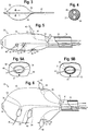
Figure 1 shows a balloon catheter having an inflatable balloon having holes formed in an outer wall, and a shaft having a delivery lumen in communication with the interior of the balloon, and wires extending out of the delivery lumen and through the interior of the balloon and out of the holes; -
Figure 2A is a cross-sectional view of one embodiment of the shaft, showing a delivery lumen, an inflation lumen for the balloon, and a wire lumen for delivering the balloon catheter over a guidewire; -
Figure 2B is another embodiment, where the shaft includes a delivery lumen and a guidewire lumen; -
Figure 2C is a schematic cross-sectional view illustrating a tube that extends from the insertion end of the shaft that is integral with the shaft, with the guidewire lumen extending through the tube; -
Figure 3 is a schematic view of a daughter balloon having a shaft and an inflation lumen; -
Figure 4 is a cross-sectional view of the shaft of the daughter balloon; -
Figure 5 is a schematic view of the daughter balloon delivered over the wire through the delivery lumen and into the balloon and out of the hole in the balloon, and inflated into engagement with the hole; -
Figure 5A illustrates a reinforcing band extending around the hole in the balloon; -
Figure 5B illustrates a mesh material embedded in the balloon wall around the hole in the balloon; -
Figure 6 is a view of multiple daughter balloons delivered into the holes of the balloon, and the balloon inflated after each of the daughter balloons have been delivered and inflated; -
Figure 7 is a cross-sectional view of the balloon catheter and the balloon in a compressed state within a delivery sheath, with wires preloaded in a delivery state; -
Figure 8 illustrates the balloon catheter delivered to a body vessel and exposed from the delivery sheath, with the wires being routed into adjacent branch vessels from the holes in the balloon; -
Figure 9 illustrates the daughter balloons delivered across the holes and inflated into engagement with the holes and extending into the branch vessels; and -
Figure 10 illustrates the balloon in an inflated condition and expanded into contact with the body vessel wall with the daughter balloons inflated into engagement with the branch vessels. - Unless specified otherwise, all technical and scientific terms used herein have the same meaning as commonly understood to one of ordinary skill in the art to which this invention belongs.
- The term "distal" means a location or direction that is, or a portion of a device that when implanted is further downstream in the direction of or with respect to blood flow. In the case of aortic intervention, distal means a location further away from the heart. In a trans-femoral approach, the distal end of a device is the end that is closer to the operator.
- The term "proximal" means a location or direction that is, or a portion of a device that when implanted is further upstream in the direction of or with respect to blood flow. In the case of aortic intervention, proximal means a location closer to the heart. In a trans-femoral approach, the proximal end of a device is the insertion end of the device.
- The term "fenestration" means an opening provided through a surface of a prosthesis from the interior of the prosthesis to the exterior of the prostheses and may have a variety of geometries, including circular, semi-circular, oval, oblong, as well as other geometries.
- The term "biocompatible" refers to a material that is substantially non-toxic in the in vivo environment of its intended use, and that is not substantially rejected by the patient's physiological system (i.e., is non-antigenic). Examples of biocompatible materials from which textile graft material can be formed include, without limitation, polyesters, such as polyethylene terephthalate; fluorinated polymers, such as polytetrafluoroethylene (PTFE) and fibers of expanded PTFE, and polyurethanes. In addition, materials that are not inherently biocompatible may be subjected to surface modifications in order to render the materials biocompatible. Examples of surface modifications include graft polymerization of biocompatible polymers on the materials surface, coating of the surface with a crosslinked biocompatible polymer, chemical modification with biocompatible functional groups, and immobilization of a compatibilizing agent such as heparin or other biocompatible substances. Thus, any fibrous material having sufficient strength to survive in the in vivo environment may be used to form a textile graft, provided the final textile is biocompatible. Fibers suitable for making textile grafts include polyethylene, polypropylene, polyaramids, polyacrylonitrile, nylon, and cellulose, in addition to the polyesters, fluorinated polymers, and polyurethanes as listed above. Furthermore, bioremodelable materials may also be used singly or in combination with the aforementioned polymer materials. The textile may be made of one or more polymers that do not require treatment or modification to be biocompatible. The graft may be constructed from woven multifilament polyester, for example and without limitation, Dacron™, produced by DuPONT. Dacron™ is known to be sufficiently biologically inert, non-biodegradable, and durable to permit safe insertion inside the human body.
- The term "prosthesis" means any device for insertion or implantation into or replacement for a body part or function of that body part. It may also mean a device that enhances or adds functionality to a physiological system. The term prosthesis may include, for example and without limitation, a stent, stent-graft, filter, valve, balloon, embolization coil, and the like.
- The term "tubular" refers to the general shape of an endoluminal device which allows the module to carry fluid along a distance or fit within a tubular structure such as an artery. Tubular prosthetic devices include single, branched, and bifurcated devices. Tubular may refer to any shape including, but not limited to, tapered, cylindrical, curvilinear, or any combination thereof. A tubular device may have a cross-sectional shape that is, circular, substantially circular or the like. However, it should be understood that the cross-sectional shape is not limited thereto, and other shapes, such as, for example, hexagonal, pentagonal, octagonal, or the like are contemplated. The term "endoluminal" refers to or describes objects that can be placed inside a lumen or a body passageway in a human or animal body. A lumen or a body passageway can be an existing lumen or a lumen created by surgical intervention. As used in this specification, the terms "lumen" or "body passageway" are intended to have a broad meaning and encompasses any duct (e.g., natural or iatrogenic) within the human body and can include a member selected from the group comprising: blood vessels, respiratory ducts, gastrointestinal ducts, and the like. "Endoluminal device" or "endoluminal prosthesis" thus describes devices that can be placed inside one of these lumens.
- The term "branch vessel" refers to a vessel that branches off from a main vessel. Examples are the celiac and renal arteries which are branch vessels to the aorta (i.e., the main vessel in this context). As another example, the hypogastric artery is a branch vessel to the common iliac, which is a main vessel in this context. Thus, it should be seen that "branch vessel" and "main vessel" are relative terms.
- "Longitudinally" refers to a direction, position or length substantially parallel with a longitudinal axis of a reference, and is the length-wise component of the helical orientation.
- "Circumferentially" refers to a direction, position, or length that encircles a longitudinal axis of reference. The term "circumferential" is not restricted to a full 360° circumferential turn or to a constant radius.
- The terms "patient," "subject," and "recipient" as used in this application refer to any animal, especially humans.
-
Figures 1-10 show asystem 10 including aballoon catheter 12 and adelivery sheath 14 for delivering and deploying theballoon catheter 12 within a patient's vasculature at a desired location. As used herein, references to an insertion end refer to the end of a device or component that is inserted first into the patient and that is opposite an operator end, which is the end that typically remains out of the body. -
Figure 1 is a schematic illustration of aballoon 18 in an expanded or partially expanded state that includesholes 34 allowing for additional balloons to pass through at least partially through awall 30 of theballoon 18. These additional balloons are not shown inFigure 1 in order to illustrate theholes 34 and other structure.Figure 1 therefore illustrates theballoon 18 in an expanded condition, but in use, theballoon 18 typically remains in a compressed position prior to the additional balloons being delivered through theholes 34 to seal theholes 34. However, in some approaches, theballoon 18 may be expanded into a partially expanded state to aid in the introduction of the further balloons, as further described below. - The
delivery sheath 14 includes aninsertion end 14a and anoperator end 14b. Theballoon catheter 12 likewise includes aninsertion end 12a and anoperator end 12b. - The
balloon catheter 12 includes a maintubular shaft 16 that extends longitudinally between aninsertion end 16a and anoperator end 16b, and aninflatable balloon 18 attached to theshaft 16 near theinsertion end 16a of theshaft 16. As shown inFigure 1 , theinsertion end 12a of theoverall balloon catheter 12 is disposed further away from the operator than theinsertion end 16a of theshaft 16. - The
shaft 16 defines aninflation lumen 20 that is in fluid communication with an interior cavity of theballoon 18. In one approach, theinflation lumen 20 may be defined by theshaft 16 and atube 21 that extends from theinsertion end 16a of theshaft 16 and into the interior of theballoon 18 and to theinsertion end 12a of theballoon catheter 12. Theshaft 16 and thetube 21 may define aninflation port 21 a that delivers inflation fluid from theinflation lumen 20 into the interior of theballoon 18, as shown inFigure 1 . In one approach, thetube 21 may be a separate component that attaches to the end of theshaft 16, as illustrated inFigure 1 . In another embodiment, as shown inFigure 2C , thetube 21 may be an integral extension of theshaft 16. In one approach, as shown inFigure 2C , thetube 21 may provide support for theballoon catheter 12, and may include the guidewire lumen W, but where inflation fluid is provided through another lumen such as adelivery lumen 22, as described below. - The
shaft 16 further defines adelivery lumen 22 extending longitudinally through theshaft 16 and configured to allow other system components to be housed therein or delivered therethrough. Thecatheter 12 andshaft 16 may be delivered with or without the use of a guidewire. In one another approach, theballoon catheter 12 may include a guidewire lumen W formed in theshaft 16 and extending through thetube 21 or other similar support structure that extends through theballoon 18, as shown inFigures 1-3 . It will be appreciated that the various lumens can be arranged in a variety of ways in theshaft 16 and the through theballoon 18, such that thedelivery lumen 22 opens into the interior of theballoon 18 and theinflation lumen 20 can provide inflation fluid to the interior of the balloon, with the guidewire lumen W extending through theballoon 18 and isolated from theinflation lumen 20. One example of a lumen arrangement is shown inFigure 2A , which shows a cross-section of theshaft 16 and the lumens extending therethrough, including guidewire lumen W,delivery lumen 22 andinflation lumen 20. -
Figure 2B illustrates an embodiment where theshaft 16 includes thedelivery lumen 22 and a guidewire lumen W, but without a separate inflation lumen. In this embodiment, inflation fluid may be delivered through thedelivery lumen 22. The guidewire lumen W extends through thetube 21 in this embodiment, as shown inFigure 2C . - In one embodiment, the
delivery lumen 22 is sized to be larger/wider than theinflation lumen 20. In particular, thedelivery lumen 22 is sized to be wide enough to facilitate delivery of additional balloons through thedelivery lumen 22, as well as multiple guidewires for each of the additional balloons, as further described below. - The
balloon 18, attached to theinsertion end 12a of thecatheter 12 as well as to theinsertion end 16a of theshaft 16, is preferably in the form of a compliant balloon, meaning that theballoon 18 will typically take the shape of the vessel in which it is deployed once inflated. Theballoon 18 is preferably sized to correspond generally to the size of the vessel to which theballoon 18 will be delivered and inflated. Theballoon 18 being in the form of a compliant balloon allows theballoon 18 to be inflated to occlude or fill a target blood vessel while limiting instances where theballoon 18 may cause further damage to the vessel wall when inflated. Thecompliant balloon 18, when inflated, will tend to take the shape of the blood vessel due to its compliant structure. The compliant, or semi-compliant in another approach,balloon 18 helps theballoon 18 accommodate variation in the vascular anatomy that may vary from patient to patient. - In the case of a traditional inflatable balloon, the balloon wall is typically intact such that the balloon will retain the inflation fluid that is introduced into the cavity defined by the balloon to inflate the balloon.
- As shown in
Figure 1 , theballoon 18 includes thewall 30 that defines aninterior cavity 32 therein. Theinterior cavity 32 is in fluid communication with theinflation lumen 20 of thecatheter 12 and thedelivery lumen 22 of theshaft 16, such that inflation fluid can be introduced into theinterior cavity 32 via theinflation lumen 20 or thedelivery lumen 22 to inflate and expand theballoon wall 30 in a manner known in the art, as well as allowing further medical devices to be introduced into theinterior cavity 32 via thedelivery lumen 22. - Furthermore, the
balloon 18 defines one ormore holes 34, or punctures or passageways or the like, in thewall 30 that permit the passage of additional structure through thewall 30. Accordingly, with theholes 34 extending through thewall 30, theballoon 18 differs from a traditional balloon in that inflation fluid introduced in a balloon with holes would leak out of the balloon absent other structure that will seal the holes. In the present approach, such structure is provided in the form of additional balloons, which are further described below. In one approach, theballoon wall 30 may include a reinforcingband 58, further described below, that surrounds each of theholes 34 to provide reinforcement to theholes 34 in response to additional balloons being inserted through theholes 34. - In one approach, the
holes 34 are generally small. Exemplary holes may be about 2-4 mm in width. The size of theholes 34 are preferably selected to be smaller than the size of the ultimate structure that will be extended through thehole 34, such that after the structure is extended through thehole 34 and left in place, theholes 34 will be generally sealed due to the larger size of the inserted structure exerting a radially outward force on theholes 34, such that theinterior cavity 32 within theballoon 18 may still be inflated in response to the introduction of inflation fluid. Accordingly, in one approach, 2-4 mm sized holes are one preferred sizing to accommodate a further balloon that inflates to about 8 mm in width, for example. - In one approach, the
balloon 18 may include fourholes holes 34a-d are located on theballoon 18 such that their location will typically correspond to the general location of branch vessels in the target delivery and deployment area. For example, the four-hole arrangement may be used in the abdominal aorta near the left and right renal arteries (LRA and RRA) and the supermesenteric artery (SMA) and celiac artery (CA). The SMA and CA are typically disposed above a patient's renal arteries, such that they are between a patient's renal arteries and the heart. - Thus, for a
balloon 18 that is designed and arranged to be delivered to this area of the patient, holes 34a and 34b can be arranged on laterally opposite sides of theballoon 18 to accommodate the LRA and RRA, withholes holes balloon 18 as each other. Differing anatomy may result in altering the arrangement of theholes 34 as needed. Further, depending on the desired location for introduction and inflation of theballoon 18, additional holes or fewer holes may be used. - The
balloon 18 defines afirst end 18a and asecond end 18b. Thefirst end 18a is preferably attached to theinsertion end 16a of theshaft 16, with thesecond end 18b being attached to theinsertion end 12a of theballoon catheter 12 at the opposite longitudinal end of theballoon 18 opposite the interface between theinsertion end 16a of theshaft 16 and thefirst end 18a of theballoon 18. Thedelivery lumen 22 includes anopening 22a at theinsertion end 16a of theshaft 16 that is in fluid communication with theinterior cavity 32 of the balloon, such that wires or other structure can be passed through thedelivery lumen 22 and into theinterior cavity 32. Thedelivery lumen 22 therefore could be used for providing inflation fluid as an alternative to theinflation lumen 20 andtube 21, with thetube 21 being used for support rather than inflation, as described above, and thetube 21 may include the guidewire lumen W but remain fluidly isolated from thecavity 32 of theballoon 18, as shown inFigure 1B . - As shown in
Figure 1 , thesystem 10 may further include one ormore wires 40 for assisting in the delivery of additional structure to theholes 34. Thewires 40 will act as guidewires for the additional structure to allow for the additional structure to be routed to the desiredhole 34. The number ofwires 40 preferably corresponds to the number ofholes 34 in theballoon 18. However, it will be appreciated that the number ofwires 40 could differ from the number ofholes 34 in some cases. Typically, eachhole 34 will have acorresponding wire 40 extending through thehole 34. - Thus, in one approach, the
wires 40 extend through thedelivery lumen 22 and out of theinsertion end 16a of theshaft 16 and into theinterior cavity 32 defined by theballoon 18. Eachindividual wire 40 may further extend through a correspondinghole 34 of theballoon 18 and out of theinterior cavity 32 of theballoon 18, such that aterminal end 42 of thewire 40 is disposed outside of theinterior cavity 32. Thewires 40 are preferably arranged in a pre-loaded state, such that they extend though theholes 34 of the balloon while theballoon 18 is housed within thedelivery sheath 14 prior to insertion into the body. Thewires 40 may be preloaded as packaged and provided to the doctor in a pre-loaded state, or thewires 40 may be loaded by the doctor prior to delivery of thecatheter 12 into the patient. In either case, thewires 40 are preloaded in thecatheter 12 in a delivery configuration prior to insertion into the patient. Thus, by being pre-loaded, thewires 40 may already extend out of theholes 34 and will not need to be routed through the generallysmall holes 34 of theballoon 18 after theballoon 18 is exposed from thesheath 14 and delivered to the desired delivery area. Accordingly, thewires 40 being pre-loaded will result in thewires 40 extending through theholes 34 prior to theballoon 18 being inflated. - In another approach, the
pre-loaded wires 40 may terminate within theballoon cavity 32 when theballoon catheter 12 is delivered in the delivery configuration, and thewires 40 may be carefully routed through theholes 34 after theballoon 18 has been exposed within the body lumen. In this approach, theballoon 18 may be partially inflated to increase the size of thecavity 32 to aid in routing thewires 40. In another approach, thewires 40 may not be pre-loaded and may be introduced through theballoon catheter 12 and into and through thecavity 32 after theballoon 18 has been delivered.Figure 7 illustrateswires 40 both extending through theholes 34 in the preloaded state and terminating within thecavity 32 in the preloaded state. - Thus, with the
wires 40 extending from thedelivery lumen 22 through thecavity 32 and out of theballoon 18 to the exterior of theballoon 18, additional components can be delivered along thewires 40 and will be routed to the correspondinghole 34 through which thewires 40 extend. - With reference now to
Figures 3-6 , thesystem 10 further includes one or more "additional," "secondary," or "daughter" balloons 50 that are configured to be delivered through thedelivery lumen 22 over thewires 40 and into engagement with theholes 34 defined by theballoon 18. -
Figures 3 and 4 shown examples of daughter balloons. The daughter balloons 50 may be attached to ashaft 52 having aninflation lumen 54 and awire lumen 56 in the manner of a traditional balloon catheter. Theinflation lumen 54 provides inflation fluid to the interior of theballoon 50 to inflate and expand theballoon 50 in a manner known in the art, and theballoon 50 andshaft 52 are deliverable over a wire via thewire lumen 56 in a known manner as well.Figure 4 illustrates one example of a lumen arrangement, showing theshaft 52 in cross-section. However, it will be appreciated that other arrangements of the lumens could be used, such as a dual lumen design for theinflation lumen 54, or a coaxial lumen design where thewire lumen 56 is disposed coaxially within theinflation lumen 54. - Thus, with reference to
Figure 5 , in one approach, individual daughter balloons 50 are deliverable overindividual wires 40 through thedelivery lumen 22 of theshaft 16 and into engagement with thehole 34 that corresponds to thewire 40 over which the particularindividual balloon 50 was delivered.Figure 5 illustrates afirst daughter balloon 50 being delivered to one of theholes 34 over thewire 40 that extends through thehole 34.Figure 5 further illustrates theother holes 34 havingwires 40 extending therethrough.Figure 5 illustrates theballoon 18 in a partially inflated state, however delivery of the daughter balloons 50 may occur when theballoon 18 is still in a compressed state and prior to any inflation. It may be difficult to inflate theballoon 18 effectively prior to delivery of each of the daughter balloons 50 due to theholes 34 being present in theballoon 18. - The daughter balloons 50 may be made from traditional medical balloon materials, and can be compliant or semi-compliant, depending on the needs of the user. The size of the daughter balloons 50 can also be selected to correspond to a patient's particular anatomy. As described above with respect to the
holes 34, the expanded width of theballoon 50 is preferably greater than the size of thehole 34, such that when theballoon 50 is expanded into engagement with thehole 34, the edge of thehole 34 will seal against the outer wall of thedaughter balloon 50. The compliant nature of theballoon 18 will allow thehole 34 to stretch to accommodate the expanded outer width of thedaughter balloon 18. In one approach, the daughter balloons 50 are more rigid than theballoon 18, such that the daughter balloons 50 will stretch theholes 34 in theballoon 18, as shown inFigure 5 . In another approach, the daughter balloons 50 may be less rigid, and in this case theholes 34 may not stretch, and instead the daughter balloons 50 would expand further on each side of thehole 34 than in thehole 34, such that the diameter of thedaughter balloon 50 on either side of thehole 34 is greater than the diameter of thehole 34, thus taking on a somewhat hourglass shape, as shown inFigure 6 . - The
balloons 50 are preferably delivered over thewires 40 in a sequential manner, such that thedelivery lumen 22 of theshaft 16 can be sized to accommodate the number ofpreloaded wires 40 in addition to allowing asingle balloon 50 to be delivered through thelumen 22, which keeps the overall width of theshaft 16 small. However, it would also be possible to increase the size of thedelivery lumen 22 to allow for delivery of more than oneballoon 50 at a time side-by-side, but this would also increase the width of theshaft 16 to a size larger than one where balloons 50 are delivered sequentially. -
Figure 6 illustrates theballoon 18 in a fully inflated state after each of the daughter balloons 50 have been delivered to the correspondingholes 34 over the correspondingwires 40. Theballoons 50 have been inflated and have created a seal with theholes 34, thereby sealing off thecavity 32 inside theballoon 18 such that theballoon 18 may be inflated.Figure 6 illustrates the example of the daughter balloons 50 taking on an hourglass shape after inflation, as described above. - Due to the expansion of the
balloons 50 while extending through theholes 34 to create the seal, theballoon 34 may also include the reinforcingband 58 disposed around the edge of theholes 34, as shown inFigure 5A . The reinforcingband 58 can help prevent tearing of theballoon 18 at the location of theholes 34 when theholes 34 are stretched, and can also help provide a seal against the expandeddaughter balloon 50. As shown inFigure 5A , the reinforcingband 58 can be in the form of an additional layer of balloon material that is bonded or adhered to the area surrounding the hole, or it could be in the form of an applied coating or curing adhesive. In another approach, as shown inFigure 5B , amesh material 59 may be embedded in thewall 30 of theballoon 18 around theholes 34. - When the daughter balloons 50 are expanded into a sealing engagement with the
holes 34 of theballoon 18, theballoon 18 will be generally sealed from inflation fluid leaking out of theballoon 18 when theballoon 18 is inflated. It has been found that the use of 8x20 mm sized daughter balloons 50 inserted into 2-4 mm holes 34 in theballoon 18 allows theballoon 18 to hold greater than 1 atm of pressure when inflation fluid is introduced into thecavity 32 to inflate theballoon 32. As shown inFigure 5 , theballoon 18 and theholes 34 thereof, the daughter balloons 50, andshaft 16, as well as other structure described above, can each includeradiopaque markers 61 disposed at various selected locations to aid in locating theballoon 18 and the various corresponding and cooperating structure at the desired location within the patient's anatomy. For example,markers 61 may be located at each of theholes 34 to assist in positioning theballoon 18 so that thewires 40 and daughter balloons 50 may be routed to the desired branch vessels. Similarly, thewires 40 may be made of a radiopaque material. - The daughter balloons 50 can be used to cannulate various branch vessels adjacent the delivered location of the
main balloon 18. This can be performed quickly and easily due to thepre-loaded wires 40 that extend through theballoon 18 in its delivery state. Thewires 40 are moveable relative to theshaft 16 and theholes 34 of theballoon 18, such that after theballoon 18 andwires 40 have been delivered, thewires 40 can be individually extended into the desired branch vessel prior to delivering thedaughter balloon 50. Accordingly, thedaughter balloon 50 will enter the desired branch vessel along thewire 40. - The
system 10 has a delivery state and a deployed state. With reference toFigure 7 , in the delivery state, theballoon 18 andshaft 16 andwires 40 are disposed within thedelivery sheath 14 and covered by thedelivery sheath 14. Thewires 40 are pre-loaded in theballoon 18.Figure 7 shows threewires 40 extending through theholes 34 in theballoon 34 such that they extend through theholes 34 and to the exterior of theballoon 18 while in the delivery state.Figure 7 also illustrates onewire 40 terminating within theballoon cavity 32. It will be appreciated that all of thewires 40 may extend out of theholes 34 in the delivery state, all of thewires 40 may terminate with thecavity 32 in the delivery state, or some of thewires 40 may extend out of theholes 34 and others of thewires 40 may terminate within theballoon cavity 32. - In the deployed state, shown in
Figure 8 , thedelivery sheath 14 is retracted relative to theballoon 18,shaft 16, andwires 40, thereby exposing theballoon 18 and thewires 14 to the surrounding vasculature. From this deployed state, thewires 40 may be routed into the desired branch vessels, and theballoons 50 may be introduced as described above and theballoon 18 may be inflated. - As shown in
Figure 8 , upon theballoon 18 being exposed by retracting thesheath 14 at the desired location, thewires 40 are routed into the desired adjacent branch vessels. As shown inFigure 9 , following positioning of thewires 40, the daughter balloons 50 are delivered over thewires 40 and into the branch vessels while also being disposed within theholes 34 of theballoon 18. Theballoons 50 are preferably delivered sequentially. However, as described above, in another approachmultiple balloons 50 may be delivered side-by-side or otherwise together if thedelivery lumen 22 is wide enough to accommodate multiple daughter balloons 50 in that arrangement. - After delivering the daughter balloons 50 over the
wires 40 and into theholes 34 of theballoon 18, the daughter balloons 50 are inflated. The daughter balloons 50 can be inflated sequentially after delivering eachindividual balloon 50, ormultiple balloons 50 may be inflated at the same time after deliveringmultiple balloons 50. In another approach, theballoons 50 could each be inflated at the same time after some or all of theballoons 50 have been delivered. - As the
balloons 50 are inflated, they can be inflated to provide support to the branch vessels. In another approach, theballoons 50 may be positioned at different areas outside of theballoon 18 outside of a branch vessel. For example, one or more of theballoons 50 could be positioned against the main vessel wall. - As shown in
Figure 10 , after each of the daughter balloons 50 have been inflated, themain balloon 18 is inflated and expanded into engagement with the main vessel wall. The previous inflation of the daughter balloons 50 provides a sealing and filling of theholes 34, such that themain balloon 18 will sufficiently inflate. - In one approach, the
balloon 18 is compliant, and the daughter balloons 50 are minimally compliant, meaning that the daughter balloons 50 can inflate to a predefined shape, causing theballoon 18 to stretch in response to inflation of the daughter balloons 50. Therefore, when theballoon 18 is inflated, it will tend to conform to the shape of the vessel wall as well as around the daughter balloons 50. In another approach, the daughter balloons 18 may be compliant and will take the shape of the vessel in which they are deployed, and inflation of theballoon 18 may alter the shape of the daughter balloons 50, depending on whether theballoon 18 or daughter balloons 50 are more rigid relative to each other. - The
main balloon 18 can be cycled between an inflated and deflated position to open up a blocked blood vessel. In this case, the daughter balloons 50 provide support to the branch vessels as themain balloon 18 is inflated and deflated. While theballoon 18 has been described as being compliant and conforming to the shape of the vessel, it will be appreciated that theballoon 18 may still be arranged to have sufficient rigidity when inflated to open up a blocked vessel. - In the case of aortic dissection, such as type B dissection, the daughter balloons 50 in their inflated state provide support to the branch vessels, while the inflation of the
main balloon 18 provides support within the true lumen, thereby allowing for filling the false lumen with embolic material. - It will be appreciated that the above arrangement may be used in various other situations where balloon support for a main vessel and branch vessels is desired.
- Throughout this specification various indications have been given as to preferred and alternative examples and aspects of the invention. However, the foregoing detailed description is to be regarded as illustrative rather than limiting and the invention is not limited to any one of the provided aspects. It should be understood that it is the appended claims, including all equivalents that are intended to define the spirit and scope of this invention.
- The disclosures in United States patent application number
US-15/631,759
Claims (16)
- A medical device system comprising:a balloon catheter including a shaft extending in a longitudinal direction and an inflatable main balloon attached to the catheter;an inflation lumen of the shaft extending longitudinally within the shaft, the inflation lumen in fluid communication with an interior cavity of the balloon for providing inflation fluid to the main balloon;a delivery lumen of the shaft extending longitudinally through the shaft, the delivery lumen in fluid communication with the interior cavity of the balloon and configured to allow additional medical devices to be delivered to the interior cavity of the main balloon;at least one inflatable daughter balloon sized and configured to be moveable through the delivery lumen and into the interior cavity of the main balloon; andat least one hole in an expandable wall portion of the main balloon, the at least one hole sized and configured to receive individual ones of the at least one daughter balloon;wherein the at least one daughter balloon is expandable into engagement with the at least one hole.
- A system according to claim 1, wherein the inflatable main balloon is a compliant balloon.
- A system according to claim 1 or 2, wherein the daughter balloon is a minimally compliant balloon.
- A system according to any preceding claim, wherein the at least one hole is pre-defined in the wall of the main balloon.
- A system according to any preceding claim, comprising at least one wire extending through the delivery lumen and into the interior cavity of the main balloon from the delivery lumen.
- A system according to claim 5, wherein the at least one wire is preloaded in the system and extends through the at least one hole when preloaded.
- A system according to claim 5 or 6, wherein the daughter balloon includes a wire lumen and is delivered over the wire into engagement with the hole.
- A system according to any preceding claim, wherein the delivery lumen has a tubular shape and is wider than the inflation lumen.
- A system according to any preceding claim, wherein the at least one daughter balloon sealingly engages the at least one hole when the at least one daughter balloon is expanded such that the main balloon is expandable via inflation after the at least one daughter balloon is inflated.
- A system according to any preceding claim, wherein the at least one hole stretches in response to inflation of the daughter balloon.
- A system according to any preceding claim, wherein the at least one daughter balloon has an expanded width that is smaller than an expanded width of the main balloon.
- A medical device system comprising:a balloon catheter including a shaft extending in a longitudinal direction and an inflatable main balloon attached to the catheter, the main balloon having an interior cavity;a delivery lumen of the shaft extending longitudinally through the shaft, the delivery lumen in fluid communication with the interior cavity of the balloon and configured to allow additional medical devices to be delivered to the interior cavity of the main balloon;at least one inflatable daughter balloon sized and configured to be moveable through the delivery lumen and into the interior cavity of the main balloon;at least one hole in an expandable wall portion of the main balloon, the at least one hole sized and configured to receive individual ones of the at least one daughter balloon; anda tubular delivery sheath extending over the balloon catheter, wherein the balloon catheter has a delivery configuration where the balloon catheter is in a retracted position relative to an insertion end of the delivery sheath and the balloon catheter compressed within the delivery sheath, and the balloon catheter has a deployed configuration where the insertion end of the delivery sheath is retracted relative to the balloon catheter to expose the balloon catheter;wherein, in the delivery configuration, the interior cavity of the main balloon is in fluid communication with an exterior of the main balloon via the at least one hole, and the at least one daughter balloons is not engaged with the at least one hole; andwherein, in the deployed configuration, the at least one daughter balloon is engaged with the at least one hole of the main balloon and the at least one daughter balloon is inflated against the at least one hole and the interior cavity of the main balloon is sealed from the exterior of the main balloon.
- A system according to claim 12, comprising at least one wire extending through the delivery lumen and out of the at least one hole in the main balloon when then main balloon is in the delivery configuration, wherein the at least one hole is pre-defined in the wall of the main balloon when the main balloon is in the delivery configuration.
- A system according to claim 12 or 13, comprising at least one wire extending through the delivery lumen and into the interior cavity of the main balloon and terminating within the interior cavity of the balloon when the main balloon is in the delivery configuration.
- A system according to claim 12, 13 or 14, wherein the at least one daughter balloon is outside of the delivery sheath and the balloon catheter when the balloon catheter and delivery sheath are in the delivery configuration.
- A system according to any preceding claim, wherein the main balloon is reinforced in an area around the at least one hole.
Applications Claiming Priority (1)
| Application Number | Priority Date | Filing Date | Title |
|---|---|---|---|
| US15/631,759 US10350395B2 (en) | 2017-06-23 | 2017-06-23 | Introducer for lumen support or dilation |
Publications (1)
| Publication Number | Publication Date |
|---|---|
| EP3421073A1 true EP3421073A1 (en) | 2019-01-02 |
Family
ID=62750901
Family Applications (1)
| Application Number | Title | Priority Date | Filing Date |
|---|---|---|---|
| EP18275086.9A Withdrawn EP3421073A1 (en) | 2017-06-23 | 2018-06-21 | Introducer for lumen support or dilation |
Country Status (2)
| Country | Link |
|---|---|
| US (1) | US10350395B2 (en) |
| EP (1) | EP3421073A1 (en) |
Families Citing this family (2)
| Publication number | Priority date | Publication date | Assignee | Title |
|---|---|---|---|---|
| US20230263629A1 (en) * | 2020-11-10 | 2023-08-24 | Edwards Lifesciences Corporation | Protected pressure-safe balloons |
| US20220370077A1 (en) * | 2021-05-19 | 2022-11-24 | The Cleveland Clinic Foundation | Jailed airway detection and airway stent hole cutting guide |
Citations (3)
| Publication number | Priority date | Publication date | Assignee | Title |
|---|---|---|---|---|
| US20120209368A1 (en) * | 2006-03-09 | 2012-08-16 | Abbott Laboratories | System and method for delivering a stent to a bifurcated vessel |
| WO2013026135A1 (en) * | 2011-08-19 | 2013-02-28 | Khalid Al-Saadon | Stent system, deployment apparatus and method for bifurcated lesion |
| WO2014029002A1 (en) * | 2012-08-20 | 2014-02-27 | Khalid Al-Saadon | Bifurcated dual-balloon catheter system for bifurcated vessels |
Family Cites Families (158)
| Publication number | Priority date | Publication date | Assignee | Title |
|---|---|---|---|---|
| US4403612A (en) | 1980-10-20 | 1983-09-13 | Fogarty Thomas J | Dilatation method |
| US4338942A (en) | 1980-10-20 | 1982-07-13 | Fogarty Thomas J | Dilatation catherter apparatus |
| US5061273A (en) * | 1989-06-01 | 1991-10-29 | Yock Paul G | Angioplasty apparatus facilitating rapid exchanges |
| US4744366A (en) | 1986-09-10 | 1988-05-17 | Jang G David | Concentric independently inflatable/deflatable multiple diameter balloon angioplasty catheter systems and method of use |
| US4748982A (en) * | 1987-01-06 | 1988-06-07 | Advanced Cardiovascular Systems, Inc. | Reinforced balloon dilatation catheter with slitted exchange sleeve and method |
| US5116318A (en) | 1989-06-06 | 1992-05-26 | Cordis Corporation | Dilatation balloon within an elastic sleeve |
| US5049132A (en) | 1990-01-08 | 1991-09-17 | Cordis Corporation | Balloon catheter for delivering therapeutic agents |
| US5163905A (en) * | 1990-01-12 | 1992-11-17 | Don Michael T Anthony | Regional perfusion dissolution catheter |
| US5342301A (en) | 1992-08-13 | 1994-08-30 | Advanced Polymers Incorporated | Multi-lumen balloons and catheters made therewith |
| DE69110467T2 (en) | 1990-06-15 | 1996-02-01 | Cortrak Medical Inc | DEVICE FOR DISPENSING MEDICINES. |
| US5318531A (en) | 1991-06-11 | 1994-06-07 | Cordis Corporation | Infusion balloon catheter |
| CA2074304C (en) * | 1991-08-02 | 1996-11-26 | Cyril J. Schweich, Jr. | Drug delivery catheter |
| US5569184A (en) * | 1992-04-29 | 1996-10-29 | Cardiovascular Dynamics, Inc. | Delivery and balloon dilatation catheter and method of using |
| US5447497A (en) | 1992-08-06 | 1995-09-05 | Scimed Life Systems, Inc | Balloon catheter having nonlinear compliance curve and method of using |
| US6623516B2 (en) | 1992-08-13 | 2003-09-23 | Mark A. Saab | Method for changing the temperature of a selected body region |
| US6217503B1 (en) | 1994-01-21 | 2001-04-17 | The Trustees Of Columbia University In The City Of New York | Apparatus and method to treat a disease process in a luminal structure |
| US5470313A (en) | 1994-02-24 | 1995-11-28 | Cardiovascular Dynamics, Inc. | Variable diameter balloon dilatation catheter |
| US5645560A (en) | 1995-12-15 | 1997-07-08 | Cardiovascular Dynamics, Inc. | Fixed focal balloon for interactive angioplasty and stent implantation |
| US6120523A (en) | 1994-02-24 | 2000-09-19 | Radiance Medical Systems, Inc. | Focalized intraluminal balloons |
| US5843116A (en) | 1996-05-02 | 1998-12-01 | Cardiovascular Dynamics, Inc. | Focalized intraluminal balloons |
| US5562620A (en) * | 1994-04-01 | 1996-10-08 | Localmed, Inc. | Perfusion shunt device having non-distensible pouch for receiving angioplasty balloon |
| US5810767A (en) * | 1994-05-11 | 1998-09-22 | Localmed, Inc. | Method and apparatus for pressurized intraluminal drug delivery |
| US5505700A (en) * | 1994-06-14 | 1996-04-09 | Cordis Corporation | Electro-osmotic infusion catheter |
| DE69626635T2 (en) | 1995-03-31 | 2003-12-18 | Boston Scientific Corp., Natick | BALLOON CATHETER WITH SEVERAL HOLES FOR DISPOSAL OF MEDICINAL PRODUCTS |
| US5865801A (en) | 1995-07-18 | 1999-02-02 | Houser; Russell A. | Multiple compartmented balloon catheter with external pressure sensing |
| US5576476A (en) | 1995-10-20 | 1996-11-19 | Asgrow Seed Company | Soybean cultivar A3732 |
| US6017363A (en) * | 1997-09-22 | 2000-01-25 | Cordis Corporation | Bifurcated axially flexible stent |
| US5823996A (en) | 1996-02-29 | 1998-10-20 | Cordis Corporation | Infusion balloon catheter |
| UA58485C2 (en) * | 1996-05-03 | 2003-08-15 | Медінол Лтд. | Method for manufacture of bifurcated stent (variants) and bifurcated stent (variants) |
| US5707358A (en) * | 1996-05-13 | 1998-01-13 | Wright; John T. M. | Dual concentric balloon catheter for retrograde cardioplegia perfusion |
| US5617878A (en) * | 1996-05-31 | 1997-04-08 | Taheri; Syde A. | Stent and method for treatment of aortic occlusive disease |
| US5833659A (en) | 1996-07-10 | 1998-11-10 | Cordis Corporation | Infusion balloon catheter |
| US5676697A (en) * | 1996-07-29 | 1997-10-14 | Cardiovascular Dynamics, Inc. | Two-piece, bifurcated intraluminal graft for repair of aneurysm |
| US6007517A (en) * | 1996-08-19 | 1999-12-28 | Anderson; R. David | Rapid exchange/perfusion angioplasty catheter |
| AU739710B2 (en) | 1996-08-23 | 2001-10-18 | Boston Scientific Limited | Stent delivery system having stent securement apparatus |
| US6077273A (en) | 1996-08-23 | 2000-06-20 | Scimed Life Systems, Inc. | Catheter support for stent delivery |
| US6123712A (en) | 1996-08-23 | 2000-09-26 | Scimed Life Systems, Inc. | Balloon catheter with stent securement means |
| US5792105A (en) | 1996-09-11 | 1998-08-11 | Boston Scientific Corporation | Multichannel balloon catheter for delivering fluid |
| US5725535A (en) | 1996-09-20 | 1998-03-10 | Hegde; Anant V. | Multiple balloon stent delivery catheter and method |
| US5924973A (en) | 1996-09-26 | 1999-07-20 | The Trustees Of Columbia University In The City Of New York | Method of treating a disease process in a luminal structure |
| US5797948A (en) | 1996-10-03 | 1998-08-25 | Cordis Corporation | Centering balloon catheter |
| EP0835673A3 (en) | 1996-10-10 | 1998-09-23 | Schneider (Usa) Inc. | Catheter for tissue dilatation and drug delivery |
| US6599316B2 (en) * | 1996-11-04 | 2003-07-29 | Advanced Stent Technologies, Inc. | Extendible stent apparatus |
| ES2273363T3 (en) * | 1996-11-04 | 2007-05-01 | Advanced Stent Technologies, Inc. | DOUBLE EXTENSIBLE STENT. |
| US6325826B1 (en) * | 1998-01-14 | 2001-12-04 | Advanced Stent Technologies, Inc. | Extendible stent apparatus |
| US6835203B1 (en) * | 1996-11-04 | 2004-12-28 | Advanced Stent Technologies, Inc. | Extendible stent apparatus |
| US6692483B2 (en) * | 1996-11-04 | 2004-02-17 | Advanced Stent Technologies, Inc. | Catheter with attached flexible side sheath |
| US7220275B2 (en) * | 1996-11-04 | 2007-05-22 | Advanced Stent Technologies, Inc. | Stent with protruding branch portion for bifurcated vessels |
| US8211167B2 (en) * | 1999-12-06 | 2012-07-03 | Boston Scientific Scimed, Inc. | Method of using a catheter with attached flexible side sheath |
| US5843027A (en) * | 1996-12-04 | 1998-12-01 | Cardiovascular Dynamics, Inc. | Balloon sheath |
| EP1009467A4 (en) | 1997-02-19 | 2001-07-25 | Condado Med Devices Corp | Multi-purpose catheters, catheter systems, and radiation treatment |
| US6096073A (en) * | 1997-02-25 | 2000-08-01 | Scimed Life Systems, Inc. | Method of deploying a stent at a lesion site located at a bifurcation in a parent vessel |
| US5833567A (en) | 1997-03-26 | 1998-11-10 | Fernandez; Angel | Inertial power transmission |
| US5868708A (en) | 1997-05-07 | 1999-02-09 | Applied Medical Resources Corporation | Balloon catheter apparatus and method |
| US5902299A (en) | 1997-07-29 | 1999-05-11 | Jayaraman; Swaminathan | Cryotherapy method for reducing tissue injury after balloon angioplasty or stent implantation |
| US6361544B1 (en) * | 1997-08-13 | 2002-03-26 | Advanced Cardiovascular Systems, Inc. | Stent and catheter assembly and method for treating bifurcations |
| US7753950B2 (en) | 1997-08-13 | 2010-07-13 | Advanced Cardiovascular Systems, Inc. | Stent and catheter assembly and method for treating bifurcations |
| US6165195A (en) | 1997-08-13 | 2000-12-26 | Advanced Cardiovascylar Systems, Inc. | Stent and catheter assembly and method for treating bifurcations |
| US6183492B1 (en) | 1997-08-28 | 2001-02-06 | Charles C. Hart | Perfusion-isolation catheter apparatus and method |
| DE19739086C1 (en) | 1997-09-06 | 1999-07-15 | Voelker Wolfram Priv Doz Dr Me | Balloon catheter |
| US6520988B1 (en) * | 1997-09-24 | 2003-02-18 | Medtronic Ave, Inc. | Endolumenal prosthesis and method of use in bifurcation regions of body lumens |
| US6330884B1 (en) * | 1997-11-14 | 2001-12-18 | Transvascular, Inc. | Deformable scaffolding multicellular stent |
| US6156053A (en) | 1998-05-01 | 2000-12-05 | Intella Interventional Systems, Inc. | Dual catheter assembly |
| US6547760B1 (en) * | 1998-08-06 | 2003-04-15 | Cardeon Corporation | Aortic catheter with porous aortic arch balloon and methods for selective aortic perfusion |
| US6196230B1 (en) * | 1998-09-10 | 2001-03-06 | Percardia, Inc. | Stent delivery system and method of use |
| US6605030B2 (en) | 1998-11-09 | 2003-08-12 | The Trustees Of Columbia University In The City Of New York | Apparatus and method for treating a disease process in a luminal structure |
| US6059824A (en) * | 1998-12-23 | 2000-05-09 | Taheri; Syde A. | Mated main and collateral stent and method for treatment of arterial disease |
| JP2003525065A (en) * | 1999-01-27 | 2003-08-26 | ボストン サイエンティフィック リミテッド | Bifurcation stent delivery system |
| US6290673B1 (en) * | 1999-05-20 | 2001-09-18 | Conor Medsystems, Inc. | Expandable medical device delivery system and method |
| US6575966B2 (en) | 1999-08-23 | 2003-06-10 | Cryocath Technologies Inc. | Endovascular cryotreatment catheter |
| US7527622B2 (en) | 1999-08-23 | 2009-05-05 | Cryocath Technologies Inc. | Endovascular cryotreatment catheter |
| US6682545B1 (en) | 1999-10-06 | 2004-01-27 | The Penn State Research Foundation | System and device for preventing restenosis in body vessels |
| US20120089220A1 (en) * | 2000-02-18 | 2012-04-12 | E.V.R. Endovascular Researches S.A. | Microcatheter |
| US8092511B2 (en) * | 2000-03-03 | 2012-01-10 | Endovascular Technologies, Inc. | Modular stent-graft for endovascular repair of aortic arch aneurysms and dissections |
| AU2001245283A1 (en) | 2000-10-11 | 2002-04-22 | Micro Thereapeutics, Inc. | Methods for treating aneurysms |
| US20020077651A1 (en) * | 2000-12-15 | 2002-06-20 | Holmes David R. | Side branch dilatation catheter |
| EP1351624B1 (en) * | 2001-01-19 | 2008-02-27 | Boston Scientific Limited | Introducer for deployment of branched prosthesis |
| US7799064B2 (en) * | 2001-02-26 | 2010-09-21 | Boston Scientific Scimed, Inc. | Bifurcated stent and delivery system |
| US20030097169A1 (en) * | 2001-02-26 | 2003-05-22 | Brucker Gregory G. | Bifurcated stent and delivery system |
| US6918925B2 (en) * | 2001-03-23 | 2005-07-19 | Hassan Tehrani | Branched aortic arch stent graft and method of deployment |
| US6605056B2 (en) | 2001-07-11 | 2003-08-12 | Scimed Life Systems, Inc. | Conformable balloon |
| AU2002350164A1 (en) * | 2001-11-08 | 2003-05-19 | William D. Hare | Rapid exchange catheter with stent deployment, therapeutic infusion, and lesion sampling features |
| US6723116B2 (en) * | 2002-01-14 | 2004-04-20 | Syde A. Taheri | Exclusion of ascending/descending aorta and/or aortic arch aneurysm |
| EP1551333A4 (en) * | 2002-06-13 | 2010-01-06 | Existent Inc | Guidewire system |
| US6858038B2 (en) * | 2002-06-21 | 2005-02-22 | Richard R. Heuser | Stent system |
| US7438722B1 (en) | 2002-09-20 | 2008-10-21 | Advanced Cardiovascular Systems, Inc. | Method for treatment of restenosis |
| US20060265043A1 (en) * | 2002-09-30 | 2006-11-23 | Evgenia Mandrusov | Method and apparatus for treating vulnerable plaque |
| US7066905B2 (en) | 2002-11-13 | 2006-06-27 | Squire James C | Method and apparatus for accurate positioning of a dual balloon catheter |
| US20040186349A1 (en) | 2002-12-24 | 2004-09-23 | Usgi Medical Corp. | Apparatus and methods for achieving endoluminal access |
| US6875220B2 (en) | 2002-12-30 | 2005-04-05 | Cybersonics, Inc. | Dual probe |
| US20040143286A1 (en) * | 2003-01-17 | 2004-07-22 | Johnson Eric G. | Catheter with disruptable guidewire channel |
| US8734501B2 (en) | 2003-10-10 | 2014-05-27 | Cook Medical Technologies Llc | Composite stent graft |
| US7553324B2 (en) | 2003-10-14 | 2009-06-30 | Xtent, Inc. | Fixed stent delivery devices and methods |
| US9278015B2 (en) * | 2003-10-16 | 2016-03-08 | Minvasys | Catheter system for stenting and drug treatment of bifurcated vessels |
| US7344557B2 (en) * | 2003-11-12 | 2008-03-18 | Advanced Stent Technologies, Inc. | Catheter balloon systems and methods |
| US7922753B2 (en) * | 2004-01-13 | 2011-04-12 | Boston Scientific Scimed, Inc. | Bifurcated stent delivery system |
| US7758572B2 (en) | 2004-05-20 | 2010-07-20 | Boston Scientific Scimed, Inc. | Medical devices and methods including cooling balloons having nanotubes |
| WO2006014819A1 (en) | 2004-07-27 | 2006-02-09 | The Cleveland Clinic Foundation | Apparatus for treating atherosclerosis |
| US8721592B2 (en) * | 2006-01-25 | 2014-05-13 | Thermopeutix, Inc. | Variable length catheter for drug delivery |
| EP1848272A2 (en) * | 2005-02-08 | 2007-10-31 | B-Balloon Ltd. | Devices and methods for treatment of vascular bifurcations |
| US9034025B2 (en) | 2005-05-23 | 2015-05-19 | Ostial Corporation | Balloon catheters and methods for use |
| US7862601B2 (en) | 2005-05-23 | 2011-01-04 | Incept Llc | Apparatus and methods for delivering a stent into an ostium |
| US8672990B2 (en) * | 2005-05-27 | 2014-03-18 | Boston Scientific Scimed, Inc. | Fiber mesh controlled expansion balloon catheter |
| US7578831B2 (en) * | 2005-06-24 | 2009-08-25 | Abbott Laboratories | Balloon catheter |
| US7942847B2 (en) | 2005-12-16 | 2011-05-17 | Interface Associates, Inc. | Multi-layer balloons for medical applications and methods for manufacturing the same |
| CN101378708B (en) * | 2006-02-09 | 2012-01-11 | 阿兰·迪比 | System for treating vascular bifurcation lesions |
| US20070208256A1 (en) * | 2006-03-03 | 2007-09-06 | Medtronic Vascular, Inc. | Multiple Branch Tubular Prosthesis and Methods |
| US20090292241A1 (en) * | 2006-06-23 | 2009-11-26 | Abbott Laboratories | Balloon catheter |
| WO2008024943A1 (en) * | 2006-08-23 | 2008-02-28 | Abbott Laboratories | Catheter system and method for delivering medical devices |
| US20080177370A1 (en) * | 2007-01-22 | 2008-07-24 | Adam Stys | Device and method for supporting a side branch of a vessel |
| ES2714583T3 (en) | 2007-02-09 | 2019-05-29 | B & D Medical Dev Llc | Pelvic balloon tamponade |
| US8814826B2 (en) | 2007-04-04 | 2014-08-26 | Abbott Cardiovascular Systems Inc. | Sequentially inflatable balloons for delivery of treatment agents |
| US20080300610A1 (en) | 2007-05-31 | 2008-12-04 | Cook Incorporated | Device for treating hardened lesions and method of use thereof |
| US8109904B1 (en) | 2007-06-25 | 2012-02-07 | Abbott Cardiovascular Systems Inc. | Drug delivery medical devices |
| US8211055B2 (en) | 2007-09-12 | 2012-07-03 | Cook Medical Technologies Llc | Drug eluting balloon |
| EP2195068B1 (en) | 2007-09-12 | 2017-07-26 | Cook Medical Technologies LLC | Balloon catheter for delivering a therapeutic agent |
| US8540758B2 (en) * | 2007-11-27 | 2013-09-24 | Vimal I. Nanavati | Bifurcation stent and delivery system |
| EP2242456A2 (en) * | 2007-12-31 | 2010-10-27 | Boston Scientific Scimed, Inc. | Bifurcation stent delivery system and methods |
| US9480826B2 (en) | 2008-03-21 | 2016-11-01 | Cagent Vascular, Llc | Intravascular device |
| US8034022B2 (en) | 2008-04-08 | 2011-10-11 | Cook Medical Technologies Llc | Weeping balloon catheter |
| US8377108B2 (en) * | 2008-06-02 | 2013-02-19 | Boston Scientific Scimed, Inc. | Staggered two balloon bifurcation catheter assembly and methods |
| WO2010024871A1 (en) | 2008-08-26 | 2010-03-04 | Med Institute, Inc. | Balloon catheters having a plurality of needles for the injection of one or more therapeutic agents |
| US8672919B2 (en) | 2008-09-18 | 2014-03-18 | Cook Medical Technologies Llc | Dual balloon catheter assembly |
| JP5577343B2 (en) | 2008-09-22 | 2014-08-20 | ボストン サイエンティフィック サイムド,インコーポレイテッド | Balloon catheter |
| US8162879B2 (en) | 2008-09-22 | 2012-04-24 | Tyco Healthcare Group Lp | Double balloon catheter and methods for homogeneous drug delivery using the same |
| US8821562B2 (en) | 2008-09-25 | 2014-09-02 | Advanced Bifurcation Systems, Inc. | Partially crimped stent |
| US8828071B2 (en) | 2008-09-25 | 2014-09-09 | Advanced Bifurcation Systems, Inc. | Methods and systems for ostial stenting of a bifurcation |
| CN102215780B (en) | 2008-09-25 | 2015-10-14 | 高级分支系统股份有限公司 | Part crimped stent |
| US9968727B2 (en) * | 2008-12-19 | 2018-05-15 | Cvdevices, Llc | Systems, devices, and methods for organ retroperfusion along with regional mild hypothermia |
| US8740843B2 (en) | 2009-04-13 | 2014-06-03 | Cook Medical Technologies Llc | Coated balloon catheter |
| WO2010127040A1 (en) * | 2009-04-28 | 2010-11-04 | Endologix, Inc. | Apparatus and method of placement of a graft or graft system |
| JP5567840B2 (en) * | 2009-09-22 | 2014-08-06 | オリンパス株式会社 | Cell injection device |
| DE102009047925A1 (en) | 2009-10-01 | 2011-06-16 | Qualimed Innovative Medizinprodukte Gmbh | Endoluminal tubular stent graft |
| US9375223B2 (en) | 2009-10-06 | 2016-06-28 | Cardioprolific Inc. | Methods and devices for endovascular therapy |
| CN102858272B (en) | 2009-12-15 | 2015-07-15 | 爱德华兹生命科学公司 | Expansion device for treatment of vascular passageways |
| ES2845398T3 (en) | 2009-12-30 | 2021-07-26 | Caliber Therapeutics Llc | Balloon catheter systems for delivery of dry drug delivery vesicles to a vessel in the body |
| US8926602B2 (en) | 2010-01-28 | 2015-01-06 | Medtronic Cryocath Lp | Triple balloon catheter |
| CN103037929B (en) * | 2010-03-06 | 2015-08-26 | 新融合血管系统有限公司 | Recovery Catheter Kit |
| WO2011119884A1 (en) | 2010-03-24 | 2011-09-29 | Advanced Bifurcation Systems, Inc | System and methods for treating a bifurcation |
| EP2549951B1 (en) | 2010-03-24 | 2017-05-10 | Advanced Bifurcation Systems, Inc. | Stent alignment during treatment of a bifurcation |
| CN103037815B (en) | 2010-03-24 | 2015-05-13 | 高级分支系统股份有限公司 | Method and system for treating furcations by temporarily opening side branches |
| US8668667B2 (en) | 2010-12-30 | 2014-03-11 | Surmodics, Inc. | Double wall catheter for delivering therapeutic agent |
| EP3449879B1 (en) | 2011-02-08 | 2020-09-23 | Advanced Bifurcation Systems Inc. | System for treating a bifurcation with a fully crimped stent |
| CA2826760A1 (en) | 2011-02-08 | 2012-08-16 | Advanced Bifurcation Systems, Inc. | Multi-stent and multi-balloon apparatus for treating bifurcations and methods of use |
| DE202011003097U1 (en) | 2011-02-23 | 2011-06-09 | Galden, Daniel, Dr. med., 56075 | Multi-balloon approximator for anastomosing hollow lumens |
| EP2517671B1 (en) * | 2011-04-28 | 2016-05-11 | Cook Medical Technologies LLC | Apparatus for facilitating deployment of an endoluminal prosthesis |
| US9937255B2 (en) | 2011-05-18 | 2018-04-10 | Nectero Medical, Inc. | Coated balloons for blood vessel stabilization |
| US9339384B2 (en) | 2011-07-27 | 2016-05-17 | Edwards Lifesciences Corporation | Delivery systems for prosthetic heart valve |
| US9730726B2 (en) * | 2011-10-07 | 2017-08-15 | W. L. Gore & Associates, Inc. | Balloon assemblies having controllably variable topographies |
| US8827953B2 (en) | 2013-01-15 | 2014-09-09 | Krishna Rocha-Singh | Apparatus and method for delivering intraluminal therapy |
| CA2909779A1 (en) * | 2013-04-16 | 2014-10-23 | Manish Mehta | Endovascular docking apparatus and method |
| US9724495B2 (en) | 2013-06-10 | 2017-08-08 | Cook Medical Technologies Llc | Weeping balloon catheter with drug delivery through dilation balloon |
| US9028443B2 (en) | 2013-07-01 | 2015-05-12 | Cook Medical Technologies Llc | Weeping balloon catheter with drug delivery balloon in fluid communication with combination lumen |
| WO2015016162A1 (en) | 2013-07-29 | 2015-02-05 | テルモ株式会社 | Biological lumen treatment device |
| US9486347B2 (en) * | 2013-12-18 | 2016-11-08 | Timothy A. M. Chuter | Balloon catheters and systems and methods for delivering stents using such catheters |
| US10940295B2 (en) * | 2015-10-13 | 2021-03-09 | Kurt W. Erickson | Multi-lumen catheter devices, systems, and methods of using the same |
| US9550046B1 (en) | 2016-02-16 | 2017-01-24 | Embolx, Inc. | Balloon catheter and methods of fabrication and use |
| US9707217B1 (en) | 2017-02-03 | 2017-07-18 | Osmotica Kereskedelmi Es Szolgaltato Kft | Dose-dumping resistant controlled release dosage form |
-
2017
- 2017-06-23 US US15/631,759 patent/US10350395B2/en active Active
-
2018
- 2018-06-21 EP EP18275086.9A patent/EP3421073A1/en not_active Withdrawn
Patent Citations (3)
| Publication number | Priority date | Publication date | Assignee | Title |
|---|---|---|---|---|
| US20120209368A1 (en) * | 2006-03-09 | 2012-08-16 | Abbott Laboratories | System and method for delivering a stent to a bifurcated vessel |
| WO2013026135A1 (en) * | 2011-08-19 | 2013-02-28 | Khalid Al-Saadon | Stent system, deployment apparatus and method for bifurcated lesion |
| WO2014029002A1 (en) * | 2012-08-20 | 2014-02-27 | Khalid Al-Saadon | Bifurcated dual-balloon catheter system for bifurcated vessels |
Also Published As
| Publication number | Publication date |
|---|---|
| US10350395B2 (en) | 2019-07-16 |
| US20180369544A1 (en) | 2018-12-27 |
Similar Documents
| Publication | Publication Date | Title |
|---|---|---|
| US5728131A (en) | Coupling device and method of use | |
| EP2564812B1 (en) | Delivery system for an endoluminal prosthesis | |
| EP2609895B1 (en) | Endoluminal prosthesis with valve arrangement | |
| US20150250481A1 (en) | Inflatable occlusion wire-balloon for aortic applications | |
| US20020177890A1 (en) | Stent graft loading and deployment device and method | |
| EP1839624A1 (en) | Prosthesis with coupling zone methods | |
| US20060206197A1 (en) | Endovascular balloon graft | |
| US20110160833A1 (en) | Implantable graft assembly | |
| US20140180393A1 (en) | Prosthesis having pivoting fenestration | |
| US20050234542A1 (en) | Endoluminal graft | |
| US20090270964A1 (en) | Toroidal balloon system and method of use | |
| US12350142B2 (en) | Systems and methods with graft body, inflatable fill channel, and filling structure | |
| US9486346B2 (en) | Balloon expandable stent graft and apparatus and method for expanding a balloon expandable stent graft | |
| EP3578136B1 (en) | Branched frozen elephant trunk device and method | |
| AU2002236790A1 (en) | Introducer for deployment of branched prosthesis | |
| US7815656B2 (en) | Method for endovascular bypass stent graft delivery | |
| EP3417904A1 (en) | Dual balloon for lumen support or dilation | |
| US10350395B2 (en) | Introducer for lumen support or dilation | |
| EP3417903A1 (en) | Offset balloons for lumen support or dilation | |
| EP3417834A1 (en) | Balloon and mesh for lumen support or dilation | |
| CN212213936U (en) | Stent implantation conveyor and implantation system | |
| US20150112418A1 (en) | Segmented Balloon Expandable Stent Graft With Reduced Foreshortening |
Legal Events
| Date | Code | Title | Description |
|---|---|---|---|
| PUAI | Public reference made under article 153(3) epc to a published international application that has entered the european phase |
Free format text: ORIGINAL CODE: 0009012 |
|
| STAA | Information on the status of an ep patent application or granted ep patent |
Free format text: STATUS: THE APPLICATION HAS BEEN PUBLISHED |
|
| AK | Designated contracting states |
Kind code of ref document: A1 Designated state(s): AL AT BE BG CH CY CZ DE DK EE ES FI FR GB GR HR HU IE IS IT LI LT LU LV MC MK MT NL NO PL PT RO RS SE SI SK SM TR |
|
| AX | Request for extension of the european patent |
Extension state: BA ME |
|
| STAA | Information on the status of an ep patent application or granted ep patent |
Free format text: STATUS: REQUEST FOR EXAMINATION WAS MADE |
|
| 17P | Request for examination filed |
Effective date: 20190613 |
|
| RBV | Designated contracting states (corrected) |
Designated state(s): AL AT BE BG CH CY CZ DE DK EE ES FI FR GB GR HR HU IE IS IT LI LT LU LV MC MK MT NL NO PL PT RO RS SE SI SK SM TR |
|
| GRAP | Despatch of communication of intention to grant a patent |
Free format text: ORIGINAL CODE: EPIDOSNIGR1 |
|
| STAA | Information on the status of an ep patent application or granted ep patent |
Free format text: STATUS: GRANT OF PATENT IS INTENDED |
|
| RIC1 | Information provided on ipc code assigned before grant |
Ipc: A61F 2/958 20130101ALI20190809BHEP Ipc: A61F 2/954 20130101ALI20190809BHEP Ipc: A61M 25/10 20130101AFI20190809BHEP |
|
| INTG | Intention to grant announced |
Effective date: 20190912 |
|
| RIN1 | Information on inventor provided before grant (corrected) |
Inventor name: ROEDER, BLAYNE A. |
|
| STAA | Information on the status of an ep patent application or granted ep patent |
Free format text: STATUS: THE APPLICATION IS DEEMED TO BE WITHDRAWN |
|
| 18D | Application deemed to be withdrawn |
Effective date: 20200123 |