EP3419494B1 - Dishwasher and conveying system therefor - Google Patents
Dishwasher and conveying system therefor Download PDFInfo
- Publication number
- EP3419494B1 EP3419494B1 EP16706386.6A EP16706386A EP3419494B1 EP 3419494 B1 EP3419494 B1 EP 3419494B1 EP 16706386 A EP16706386 A EP 16706386A EP 3419494 B1 EP3419494 B1 EP 3419494B1
- Authority
- EP
- European Patent Office
- Prior art keywords
- rack
- displaced
- dishwasher
- path
- conveying system
- Prior art date
- Legal status (The legal status is an assumption and is not a legal conclusion. Google has not performed a legal analysis and makes no representation as to the accuracy of the status listed.)
- Active
Links
Images



Classifications
-
- A—HUMAN NECESSITIES
- A47—FURNITURE; DOMESTIC ARTICLES OR APPLIANCES; COFFEE MILLS; SPICE MILLS; SUCTION CLEANERS IN GENERAL
- A47L—DOMESTIC WASHING OR CLEANING; SUCTION CLEANERS IN GENERAL
- A47L15/00—Washing or rinsing machines for crockery or tableware
- A47L15/42—Details
- A47L15/50—Racks ; Baskets
- A47L15/506—Arrangements for lifting racks for loading or unloading purposes
Definitions
- Embodiments herein relate to household appliances, such as dishwashers, subsystems thereof and the like.
- a dishwasher and a conveying system for conveying a rack of the dishwasher are disclosed.
- Household appliances are provided in a wide range of varieties, including dishwashers and the like.
- dishwashers any dishwasher, but maybe in particular for domestic dishwashers, a factor that is appealing to users thereof relate to user-friendliness of the dishwasher.
- a known dishwasher has been provided with an elevating rack. Thanks to that it is possible to elevate the rack, a user of the dishwasher may more comfortably load on and off articles to/from the rack. In this context, the user may more comfortably load on and off articles, since the user will not need reach downwards as much as if the rack was not possible to elevate.
- WO2014/033092 discloses a sliding and pivoting mechanism of a rack of a domestic appliance for extending and raising the rack out of a body of the domestic appliance.
- the sliding and pivoting mechanism has at least two pivoting arms which are fixed rotatably to at least one of the side walls of the body with a first end parallel to the plane of the side walls, and are arranged spaced apart parallel to each other, wherein a guide rail is fixed pivotably to respective second ends of the pivoting arms parallel to the plane of the side walls in such a manner that the guide rail can be pivoted out of a lower position within the body into a raised, upper position at least partially outside the body, and at least one running rail which is displaceable linearly in the guide rail and to which the rack is fastened, wherein the sliding and pivoting mechanism has a locking mechanism which is arranged on the guide rail and on one of the pivoting arms and is actuable by an activator fixed on the running rail in order to prevent a simultaneous pivot
- a predetermined position is defined - any pivoting of the rack not being possible until the predetermined position has been reached.
- the pivoting of the sliding and pivoting mechanism is thus locked in the raised, upper position and in the lower position, in sliding of the rack is possible, up until the activator actuates the pivoting arms at the predetermined position.
- WO2014/033092 further discloses a dishwasher in which the sliding and pivoting mechanism is installed to allow a rack of the dishwasher to be pivoted and slid to facilitate on/off-loading of articles to/from the rack.
- EP3085294A1 discloses a dishwasher with a conveying system comprising a rack elevating arrangement and a locking arrangement for releasably locking the rack in an intermediate position.
- a user of the dishwasher Upon access to an interior of the dishwasher in order to execute various maintenance tasks, a user of the dishwasher need to uncomfortably reach down under the pivoted rack. When reaching under the rack, the user may support her/him-self - to mitigate the discomfort of reaching down under the rack - by leaning on a door of the dishwasher.
- the door e.g. hinges of the door, may break due to weight of the user.
- the various maintenance tasks include e.g. cleaning of filters and re-filling of dishwasher consumables, such as salt and the like.
- a problem is hence how to improve user-friendliness of a dishwasher having an elevateable rack.
- a related problem is how to enable improved user-friendliness of a dishwasher having an elevateable rack by providing an improved system for conveying a rack of a dishwasher, such as the above mentioned sliding and pivoting mechanism.
- An object may be to improve user-friendliness of dishwashers of the above mentioned kind.
- this object is achieved by a dishwasher comprising a rack, and a below described conveying system for conveying the rack of the dishwasher.
- the dishwasher comprises a further rack, wherein an interior of the dishwasher is accessible via a space between the rack and the further rack when the rack is in the intermediate position.
- the space may be formed between the rack and an upper periphery of an aperture of the dishwasher.
- Another object may be to enable improved user-friendliness of the dishwashers of the above mentioned kind.
- this object is achieved by a conveying system for conveying a rack of a dishwasher between a displaced position and a start position along a path.
- the displaced position is defined by that the rack is displaced with respect to the start position in at least a first direction perpendicular to a main extension plane of the rack.
- the conveying system comprises an elevating arrangement arranged to bias the rack towards the displaced position when the rack is located at a portion of the path.
- the conveying system comprises a locking arrangement arranged to releasably lock the rack in an intermediate position between the displaced position and the start position when the rack is located at the portion of the path. In this manner, the rack is prevented from being biasedly retracted to the displaced position or the rack is prevented from being displaced away from the intermediate position due to weight of articles carried by the rack.
- the locking arrangement is arranged to releasably lock the rack in the intermediate position, the rack is temporarily, i.e. as long as the locking arrangement does not release the rack from the intermediate position, held steady without being displaced towards the displaced position or the start position.
- the path is at least partly described by a straight line continued by an arc, wherein the rack, when in the displaced position, is located at a first end of the path, wherein the portion of the path includes the first end and the arc, wherein the rack, when in the start position, is located at a second end of the path, wherein a further portion of the path includes the second end and the straight line.
- kitchenware loaded onto the rack avoids collision with an interior roof of the dishwasher, or any existing further rack, typically placed above the rack.
- the locking arrangement comprises a protruding element being displaceable between a first location and a second location
- the elevating arrangement comprises an opening arranged to receive the protruding element, wherein the protruding element and the opening move relatively each other when the rack is conveyed between the displaced position and the start position, wherein the first location is defined by that the protruding element is displaced to be received by the opening when the rack is in the intermediate position, wherein the second location is defined by that the protruding element is displaced to allow the rack to be freely conveyed between the displaced position and the start position.
- the locking arrangement may be realized efficiently using a small number of parts.
- An advantage is that the locking arrangement may be robust and not prone to break.
- Figure 1 depicts an exemplifying dishwasher 1 according to embodiments herein.
- the dishwasher 1 comprises a rack 2, which is conveyable between a displaced position and a start position.
- the displaced and start positions will be further illustrated with reference to e.g. Figure 2 and Figure 5 .
- the rack 2 has a main extension plane P1, along which the rack 2 is capable of carrying articles 3, such as dinnerware, plates, glasses, bowls, pots, kitchenware or the like.
- the articles 3 may thus be put at or on the main extension plane P1.
- the rack 2 may typically be provided with various supporting elements (not shown) for supporting the articles 3.
- the dishwasher 1 may comprise a further rack 4, which is slidable in and out of the dishwasher 1 according to known manners.
- the further rack 4 may similarly to the rack 2 carry further articles 5. No further known details of the further rack 4 are provided here for simplicity of description.
- the dishwasher 1 comprises a casing 6 .
- the casing 6 is provided with an aperture 7 for allowing the rack 2 and/or the further rack 4 to be conveyed in and out of the dishwasher for on/off loading of the articles 3, 5.
- the dishwasher 1 further comprises a door 8 hinged at a periphery of the aperture 7, whereby the aperture 7 may be closed or opened A1 by means of the door 8.
- the dishwasher 1 comprises a washtub 9 for housing the rack 2 and/or the further rack 4.
- a washtub 9 for housing the rack 2 and/or the further rack 4.
- 5 water is injected in to the washtub 9 by means of rotatable arms (not shown) according to known manners.
- the dishwasher 1 comprises a conveying system 100 for conveying the rack 2 of the dishwasher 1 between the displaced position and the start position along a path.
- a conveying system 100 for conveying the rack 2 of the dishwasher 1 between the displaced position and the start position along a path.
- the displaced and start positions as well as the path will be further illustrated with reference to e.g. Figure 2 .
- the rack 2 does not form part of the conveying system 100.
- the conveying system 100 comprises an elevating arrangement 110 arranged to bias the rack 2 towards the displaced position.
- the conveying system 100 further comprises a locking arrangement 121, 122 arranged to releasably lock the rack 2 in an intermediate position between the displaced position and the start position.
- the rack 2 is prevented from being biasedly retracted to the displaced position or the rack 2 is prevented from being displaced away from the intermediate position, i.e. displaced towards the start position, due to weight of articles 3 carried by the rack 2.
- the conveying system 100 may additionally comprise a rail 130 arranged to convey the rack 2 along the main extension plane P1 of the rack 2.
- the locking arrangement is releasably engagable onto the rack.
- improved user-friendliness may be provided to existing conveying system, should a suitable opening be provided, e.g. drilled, or exist in the elevating arrangement 110, such as in an elevating arm thereof as disclosed below.
- the elevating arrangement 110 may comprise a biasing member 111, such as a spring, helical spring, gas spring or the like.
- the biasing member 111 is arranged to bias the rack 2 towards the displaced position.
- the elevating arrangement 110 may further comprise an elevating arm 112 pivotably connected, directly or indirectly, to the rail 130 with respect to a rail pivoting point 113.
- the rail pivoting point 113 moves in relation to the dishwasher 1 as the rack 2 is conveyed between the displaced position and the start position.
- the elevating arrangement 110 may comprise a further elevating arm (not shown), which also may be pivotably connected to the rail 130.
- the further elevating arm may facilitate displacement of the rack, while ensuring that the main extension plane P1 of the rack 2 is not titled according to known manners.
- a first end of the biasing member 111 is pivotably connected, e.g. with respect to a first pivoting point 114, to the elevating arm 112.
- the first pivoting point 114 moves in relation to the dishwasher 1 as the rack 2 is conveyed between the displaced position and the start position.
- a second end of the biasing member 111 is pivotably connected, e.g. with respect to a second pivoting point 115, to a mounting structure 116 of the elevating arrangement 110.
- the mounting structure 116 is slidable along the main extension plane P1 of the rack 2.
- the second pivoting point 115 does not move relatively the dishwasher 1.
- the mounting structure 116 may be fixed with respect to the washtub 9, i.e. also with respect to the entire dishwasher 1.
- the elevating arm 112 has a longitudinal geometrical axis at which an elevating pivoting point 117 is located. Similarly to the second pivoting point 115, the elevating pivoting point 117 may be slidable along the main extension plane P1 of the rack 2, but during the displacement of the rack in the direction perpendicular to the main extension plane P1 the elevating pivoting point 117 does not move.
- the biasing member 111 is configured and arranged to provide biasing by means of pulling at the first pivoting point 114. In other examples (not shown), the biasing member 111 may be configured and arranged to provide biasing by means of pushing at a point below the elevating pivoting point 117.
- Figure 2 which illustrates the rack 2 of the dishwasher 1 when put, e.g. by a user of the dishwasher 1, in the displaced position, the start position and the intermediate position.
- the displaced position 201 is defined by that the rack 2 is displaced with respect to the start position 202 in at least a first direction P2 perpendicular to the main extension plane P1 of the rack 2.
- the first direction P2 points away from the main extension plane P1 from a side of the rack 2.
- the side of the rack 2 is adapted to carry the articles 3.
- the first direction P2 points upwards.
- the displaced position 201 may be further defined by that the rack 2 is displaced with respect to the start position 202 in a second direction P3 along the main extension plane P1 of the rack 2. With respect to the washtub 9, the second direction P3 points out of the washtub 9. In this manner, the rack 2 is brought further out of the dishwasher when moved from the start position 202 to the displaced position 201.
- the start position 202 may be defined by that the rack 2 is freely movable along a portion 203 of the path 204 (indicated by entire bold line) when the locking arrangement 121, 122 does not releasably lock the rack 2 in the intermediate position 207.
- the movement along the portion 204 of the path 203 may be caused by the user and/or weight of articles 3 and/or biasing achieved by means of the elevating arrangement 110.
- the path 203 may optionally comprise a further portion 205.
- the elevating arrangement 110 is arranged to bias the rack 2 towards the displaced position when the rack 2 is located at the portion 204 of the path 203. This means that the rack 2 is, as mentioned, freely movable 206 along the portion 204 when rack 2 is not locked in the intermediate position 207. However, the elevating arrangement 110 is still arranged to bias the rack 2 towards the displaced position 201 when the rack 2 is located at the further portion of the path 203, albeit movement due to the biasing is prevented since the elevating arrangement 110 is locked such as to keep the rack 2 along a plane including both the start position and a closed position 208 .
- the elevating arrangement 110 may be configured to lock the rack 2 in the displaced position 201 according to known manners. In this manner, the rack may be prevented from being displaced from the displaced position due to weight of the articles 3 loaded onto the rack 2.
- the biasing of the elevating arrangement 110 will typically force the rack to the displaced position 201, but as explained above when the user loads articles 3 onto the rack 2 the elevating arrangement 110 may be configured to lock the rack 2 such at to prevent the rack 2 from sinking downwards due to weight of articles 3.
- the closed position 208 may be defined by that the dishwasher 1 is operable for washing of articles 3 carried by the rack 2.
- the door 8 is closable when the rack 2 is in the closed position 208.
- the dishwasher 1 is configured to only allow operation for washing of at least the articles 3 when the door 8 is closed against the aperture 7.
- the path 204 is at least partly described by a straight line, e.g. drawn between the start position 202 and the closed position 208, wherein the straight line is continued by an arc, e.g. draw between the displaced position 201 and the start position 202.
- the portion 203 of the path 204 may comprise the arc.
- the further portion 205 of the path 204 may comprise the straight line.
- the portion 203 and/or the further portion 205 may be shaped differently.
- the portion 203 may assume a shape of a quarter of an arc, a bent line, a hyperbola, an exponential function or the like.
- the further portion 205 may assume a shape of a slightly bent line, either upwards or downwards, multiple tiny waves etc. In general, the further portion may assume a shape of a substantially straight line.
- the rack 2 when in the displaced position 201, may be located at a first end of the path 204, wherein the portion 203 of the path 204 includes the first end and the arc.
- the intermediate position 203 allows the interior of the dishwasher 1 to be access via a space between the rack 2 and the further rack 4. Alternatively, if no further rack exists, the space is between the rack 2 and an upper periphery of the aperture 7.
- the space may typically be adapted to receive a hand 8 of the user, i.e. the space may typically be large enough for the hand 8 to pass through. Moreover, the space may be large enough to allow e.g. a filter to pass through.
- the filter is normally removably mounted at a bottom of the washtub 9. The filter prevents food remains and the like from being exhausted out of the washtub as is known in the art.
- the space allows the user to easily access e.g. the interior of the dishwasher 1, whereby salt, or other materials/fluids that the dishwasher 1 may make use of, may be refilled for known purposes of treating water, such as decalcification of water.
- Figure 4 illustrates an exemplifying conveying arrangement 100 including the locking arrangement 121, 122, which is described in more detail with reference to Figure 7 and 8 .
- Figure 4 illustrates the exemplifying conveying arrangement 100 when the rack 2 is in the closed position 208.
- the elevating arrangement 110 assumes a number of locked positions, all being at substantially the same plane as the main extension plane P1 of the rack 2 when conveyed between the closed position and the start position.
- the elevating arrangement 110 is prevented from biasedly displace the rack 2 towards the displaced position 201, e.g. in order to raise the rack 2 above the main extension plane P1 of the rack 2 when the rack 2 is at the start and/or closed positions 202, 208.
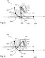
- Figure 5 illustrates the exemplifying conveying arrangement 100 when the rack 2 is in the start position 202.
- the elevating arrangement 220 is no longer prevented from biasedly displace the rack 2 towards the displaced position 201, should the rack 2 be empty or weight of articles 3 thereon so permit.
- Figure 6 illustrates the exemplifying conveying arrangement 100 when the rack 2 is in the intermediate position 207.
- the user manually releasably locks the rack 2 in the intermediate position 207.
- the intermediate position 207 may be reached from the displaced position 201, e.g. due to weight of articles 3 or due to pushing by the user.
- the intermediate position 207 may be reached from the start position 202 due to biasing provided by the elevating arrangement 110.
- the biasing member 111 has been retracted as compared to in Figure 5 .
- the locking arrangement 121, 122 may comprise a protruding element 801 being displaceable between a first location, illustrated in Figure 7 , and a second location, illustrated in Figure 8 .
- the elevating arrangement 110 i.e. the elevating arm 112 of the elevating arrangement 110, comprises an opening 121 arranged to receive the protruding element 801.
- the protruding element 801 and the opening 121 move relatively each other when the rack 2 is conveyed between the displaced position and the start position.
- the first location is defined by that the protruding element 801 is displaced to be received by the opening 121 when the rack 2 is in the intermediate position.
- the second location, as shown in Figure 8 is defined by that the protruding element 804 is displaced to allow the rack 2 to be freely conveyed, i.e. as determined by biasing, weight of articles or the user, between the displaced position and the start position.
- the common abbreviation "e.g.” which derives from the Latin phrase “exempli gratia,” may be used to introduce or specify a general example or examples of a previously mentioned item, and is not intended to be limiting of such item. If used herein, the common abbreviation “i.e.”, which derives from the Latin phrase “id est,” may be used to specify a particular item from a more general recitation.
- the common abbreviation “etc.”, which derives from the Latin expression “et cetera” meaning “and other things” or “and so on” may have been used herein to indicate that further features, similar to the ones that have just been enumerated, exist.
Landscapes
- Washing And Drying Of Tableware (AREA)
Description
- Embodiments herein relate to household appliances, such as dishwashers, subsystems thereof and the like. In particular, a dishwasher and a conveying system for conveying a rack of the dishwasher are disclosed.
- Household appliances are provided in a wide range of varieties, including dishwashers and the like. For any dishwasher, but maybe in particular for domestic dishwashers, a factor that is appealing to users thereof relate to user-friendliness of the dishwasher.
- In order to improve user-friendliness, a known dishwasher has been provided with an elevating rack. Thanks to that it is possible to elevate the rack, a user of the dishwasher may more comfortably load on and off articles to/from the rack. In this context, the user may more comfortably load on and off articles, since the user will not need reach downwards as much as if the rack was not possible to elevate.
- Many known systems for elevation of the rack of the dishwasher exist. For example,
WO2014/033092 discloses a sliding and pivoting mechanism of a rack of a domestic appliance for extending and raising the rack out of a body of the domestic appliance. The sliding and pivoting mechanism has at least two pivoting arms which are fixed rotatably to at least one of the side walls of the body with a first end parallel to the plane of the side walls, and are arranged spaced apart parallel to each other, wherein a guide rail is fixed pivotably to respective second ends of the pivoting arms parallel to the plane of the side walls in such a manner that the guide rail can be pivoted out of a lower position within the body into a raised, upper position at least partially outside the body, and at least one running rail which is displaceable linearly in the guide rail and to which the rack is fastened, wherein the sliding and pivoting mechanism has a locking mechanism which is arranged on the guide rail and on one of the pivoting arms and is actuable by an activator fixed on the running rail in order to prevent a simultaneous pivoting and sliding movement. Thanks to the activator a predetermined position is defined - any pivoting of the rack not being possible until the predetermined position has been reached. The pivoting of the sliding and pivoting mechanism is thus locked in the raised, upper position and in the lower position, in sliding of the rack is possible, up until the activator actuates the pivoting arms at the predetermined position. - Aforementioned
WO2014/033092 further discloses a dishwasher in which the sliding and pivoting mechanism is installed to allow a rack of the dishwasher to be pivoted and slid to facilitate on/off-loading of articles to/from the rack.EP3085294A1 discloses a dishwasher with a conveying system comprising a rack elevating arrangement and a locking arrangement for releasably locking the rack in an intermediate position. - Upon access to an interior of the dishwasher in order to execute various maintenance tasks, a user of the dishwasher need to uncomfortably reach down under the pivoted rack. When reaching under the rack, the user may support her/him-self - to mitigate the discomfort of reaching down under the rack - by leaning on a door of the dishwasher. The door, e.g. hinges of the door, may break due to weight of the user. The various maintenance tasks include e.g. cleaning of filters and re-filling of dishwasher consumables, such as salt and the like.
- A problem is hence how to improve user-friendliness of a dishwasher having an elevateable rack. A related problem is how to enable improved user-friendliness of a dishwasher having an elevateable rack by providing an improved system for conveying a rack of a dishwasher, such as the above mentioned sliding and pivoting mechanism.
- An object may be to improve user-friendliness of dishwashers of the above mentioned kind.
- According to an aspect, this object is achieved by a dishwasher comprising a rack, and a below described conveying system for conveying the rack of the dishwasher.
- In some embodiments, the dishwasher comprises a further rack, wherein an interior of the dishwasher is accessible via a space between the rack and the further rack when the rack is in the intermediate position. In other examples, the space may be formed between the rack and an upper periphery of an aperture of the dishwasher. In this manner, user-friendliness of the dishwasher is improved thanks to that the user may simply reach down into the interior through the space, when the user performs maintenance, e.g. empties a filter of the dishwasher or adds salt, for known purposes.
- Another object may be to enable improved user-friendliness of the dishwashers of the above mentioned kind.
- According to another aspect, this object is achieved by a conveying system for conveying a rack of a dishwasher between a displaced position and a start position along a path. The displaced position is defined by that the rack is displaced with respect to the start position in at least a first direction perpendicular to a main extension plane of the rack. The conveying system comprises an elevating arrangement arranged to bias the rack towards the displaced position when the rack is located at a portion of the path. Moreover, the conveying system comprises a locking arrangement arranged to releasably lock the rack in an intermediate position between the displaced position and the start position when the rack is located at the portion of the path. In this manner, the rack is prevented from being biasedly retracted to the displaced position or the rack is prevented from being displaced away from the intermediate position due to weight of articles carried by the rack.
- Thanks to that the locking arrangement is arranged to releasably lock the rack in the intermediate position, the rack is temporarily, i.e. as long as the locking arrangement does not release the rack from the intermediate position, held steady without being displaced towards the displaced position or the start position. Thus, enabling improved user-friendliness of the dishwasher as described above.
- In some embodiments, the path is at least partly described by a straight line continued by an arc, wherein the rack, when in the displaced position, is located at a first end of the path, wherein the portion of the path includes the first end and the arc, wherein the rack, when in the start position, is located at a second end of the path, wherein a further portion of the path includes the second end and the straight line.
- Thanks to the straight line, kitchenware loaded onto the rack avoids collision with an interior roof of the dishwasher, or any existing further rack, typically placed above the rack.
- In some embodiments, the locking arrangement comprises a protruding element being displaceable between a first location and a second location, and wherein the elevating arrangement comprises an opening arranged to receive the protruding element, wherein the protruding element and the opening move relatively each other when the rack is conveyed between the displaced position and the start position, wherein the first location is defined by that the protruding element is displaced to be received by the opening when the rack is in the intermediate position, wherein the second location is defined by that the protruding element is displaced to allow the rack to be freely conveyed between the displaced position and the start position.
- In this manner, the locking arrangement may be realized efficiently using a small number of parts. An advantage is that the locking arrangement may be robust and not prone to break.
- The various aspects of embodiments disclosed herein, including particular features and advantages thereof, will be readily understood from the following detailed description and the accompanying drawings, in which:
-
Figure 1 is a side view illustrating an embodiment of the dishwasher, -
Figure 2 is another side view illustrating the dishwasher ofFigure 1 , -
Figure 3 is a further side view illustrating the dishwasher ofFigure 1 , -
Figure 4 is a side view illustrating the conveying system of the dishwasher inFigure 1 , -
Figure 5 is another side view illustrating the conveying system, -
Figure 6 is a further side view illustrating the conveying system, -
Figure 7 is a perspective view illustrating an exemplifying locking arrangement of the conveying system, and -
Figure 8 is another perspective view illustrating the exemplifying locking arrangement. - Throughout the following description similar reference numerals have been used to denote similar features, such as parts, items, elements, units, protrusions, openings, apertures or the like, when applicable.
-
Figure 1 depicts anexemplifying dishwasher 1 according to embodiments herein. - The
dishwasher 1 comprises arack 2, which is conveyable between a displaced position and a start position. The displaced and start positions will be further illustrated with reference to e.g.Figure 2 andFigure 5 . - The
rack 2 has a main extension plane P1, along which therack 2 is capable of carryingarticles 3, such as dinnerware, plates, glasses, bowls, pots, kitchenware or the like. Thearticles 3 may thus be put at or on the main extension plane P1. Therack 2 may typically be provided with various supporting elements (not shown) for supporting thearticles 3. - Additionally, the
dishwasher 1 may comprise afurther rack 4, which is slidable in and out of thedishwasher 1 according to known manners. Thefurther rack 4 may similarly to therack 2 carryfurther articles 5. No further known details of thefurther rack 4 are provided here for simplicity of description. - Furthermore, the
dishwasher 1 comprises acasing 6. Thecasing 6 is provided with anaperture 7 for allowing therack 2 and/or thefurther rack 4 to be conveyed in and out of the dishwasher for on/off loading of thearticles dishwasher 1 further comprises adoor 8 hinged at a periphery of theaperture 7, whereby theaperture 7 may be closed or opened A1 by means of thedoor 8. - Typically, the
dishwasher 1 comprises awashtub 9 for housing therack 2 and/or thefurther rack 4. During washing of thearticles washtub 9 by means of rotatable arms (not shown) according to known manners. - Moreover, the
dishwasher 1 comprises a conveyingsystem 100 for conveying therack 2 of thedishwasher 1 between the displaced position and the start position along a path. As mentioned above, the displaced and start positions as well as the path will be further illustrated with reference to e.g.Figure 2 . Notably, therack 2 does not form part of the conveyingsystem 100. - The conveying
system 100 comprises an elevatingarrangement 110 arranged to bias therack 2 towards the displaced position. - The conveying
system 100 further comprises alocking arrangement rack 2 in an intermediate position between the displaced position and the start position. - In this manner, the
rack 2 is prevented from being biasedly retracted to the displaced position or therack 2 is prevented from being displaced away from the intermediate position, i.e. displaced towards the start position, due to weight ofarticles 3 carried by therack 2. - The conveying
system 100 may additionally comprise arail 130 arranged to convey therack 2 along the main extension plane P1 of therack 2. - It may here be noted that the locking arrangement is releasably engagable onto the rack. In this manner, improved user-friendliness may be provided to existing conveying system, should a suitable opening be provided, e.g. drilled, or exist in the elevating
arrangement 110, such as in an elevating arm thereof as disclosed below. - In more detail, the elevating
arrangement 110 may comprise a biasingmember 111, such as a spring, helical spring, gas spring or the like. The biasingmember 111 is arranged to bias therack 2 towards the displaced position. - The elevating
arrangement 110 may further comprise an elevatingarm 112 pivotably connected, directly or indirectly, to therail 130 with respect to arail pivoting point 113. Therail pivoting point 113 moves in relation to thedishwasher 1 as therack 2 is conveyed between the displaced position and the start position. The elevatingarrangement 110 may comprise a further elevating arm (not shown), which also may be pivotably connected to therail 130. The further elevating arm may facilitate displacement of the rack, while ensuring that the main extension plane P1 of therack 2 is not titled according to known manners. - A first end of the biasing
member 111 is pivotably connected, e.g. with respect to afirst pivoting point 114, to the elevatingarm 112. Thefirst pivoting point 114 moves in relation to thedishwasher 1 as therack 2 is conveyed between the displaced position and the start position. - A second end of the biasing
member 111 is pivotably connected, e.g. with respect to asecond pivoting point 115, to a mountingstructure 116 of the elevatingarrangement 110. Preferably, the mountingstructure 116 is slidable along the main extension plane P1 of therack 2. However, during displacement of the rack in a direction perpendicular to the main extension plane P1, thesecond pivoting point 115 does not move relatively thedishwasher 1. In other examples, it may be that the mountingstructure 116 may be fixed with respect to thewashtub 9, i.e. also with respect to theentire dishwasher 1. - The elevating
arm 112 has a longitudinal geometrical axis at which an elevatingpivoting point 117 is located. Similarly to thesecond pivoting point 115, the elevatingpivoting point 117 may be slidable along the main extension plane P1 of therack 2, but during the displacement of the rack in the direction perpendicular to the main extension plane P1 the elevatingpivoting point 117 does not move. - In
Figure 1 , the biasingmember 111 is configured and arranged to provide biasing by means of pulling at thefirst pivoting point 114. In other examples (not shown), the biasingmember 111 may be configured and arranged to provide biasing by means of pushing at a point below the elevatingpivoting point 117. - Now turning to
Figure 2 , which illustrates therack 2 of thedishwasher 1 when put, e.g. by a user of thedishwasher 1, in the displaced position, the start position and the intermediate position. - The displaced
position 201 is defined by that therack 2 is displaced with respect to thestart position 202 in at least a first direction P2 perpendicular to the main extension plane P1 of therack 2. The first direction P2 points away from the main extension plane P1 from a side of therack 2. The side of therack 2 is adapted to carry thearticles 3. When thedishwasher 1 stands in an upright position, which e.g. allows thedishwasher 1 to be operated normally, the first direction P2 points upwards. - The displaced
position 201 may be further defined by that therack 2 is displaced with respect to thestart position 202 in a second direction P3 along the main extension plane P1 of therack 2. With respect to thewashtub 9, the second direction P3 points out of thewashtub 9. In this manner, therack 2 is brought further out of the dishwasher when moved from thestart position 202 to the displacedposition 201. - The
start position 202 may be defined by that therack 2 is freely movable along aportion 203 of the path 204 (indicated by entire bold line) when thelocking arrangement rack 2 in theintermediate position 207. The movement along theportion 204 of thepath 203 may be caused by the user and/or weight ofarticles 3 and/or biasing achieved by means of the elevatingarrangement 110. - The
path 203 may optionally comprise afurther portion 205. - Returning to the elevating
arrangement 110, it may be noted that the elevatingarrangement 110 is arranged to bias therack 2 towards the displaced position when therack 2 is located at theportion 204 of thepath 203. This means that therack 2 is, as mentioned, freely movable 206 along theportion 204 whenrack 2 is not locked in theintermediate position 207. However, the elevatingarrangement 110 is still arranged to bias therack 2 towards the displacedposition 201 when therack 2 is located at the further portion of thepath 203, albeit movement due to the biasing is prevented since the elevatingarrangement 110 is locked such as to keep therack 2 along a plane including both the start position and aclosed position 208. - Moreover, the elevating
arrangement 110 may be configured to lock therack 2 in the displacedposition 201 according to known manners. In this manner, the rack may be prevented from being displaced from the displaced position due to weight of thearticles 3 loaded onto therack 2. When therack 2 is empty, i.e. not loaded witharticles 3 or loaded withfew articles 3, the biasing of the elevatingarrangement 110 will typically force the rack to the displacedposition 201, but as explained above when the user loadsarticles 3 onto therack 2 the elevatingarrangement 110 may be configured to lock therack 2 such at to prevent therack 2 from sinking downwards due to weight ofarticles 3. - The
closed position 208 may be defined by that thedishwasher 1 is operable for washing ofarticles 3 carried by therack 2. Typically, thedoor 8 is closable when therack 2 is in theclosed position 208. In many cases, thedishwasher 1 is configured to only allow operation for washing of at least thearticles 3 when thedoor 8 is closed against theaperture 7. - As an example, the
path 204 is at least partly described by a straight line, e.g. drawn between thestart position 202 and theclosed position 208, wherein the straight line is continued by an arc, e.g. draw between thedisplaced position 201 and thestart position 202. Theportion 203 of thepath 204 may comprise the arc. Thefurther portion 205 of thepath 204 may comprise the straight line. In other examples, theportion 203 and/or thefurther portion 205 may be shaped differently. For example, theportion 203 may assume a shape of a quarter of an arc, a bent line, a hyperbola, an exponential function or the like. Thefurther portion 205 may assume a shape of a slightly bent line, either upwards or downwards, multiple tiny waves etc. In general, the further portion may assume a shape of a substantially straight line. - The
rack 2, when in the displacedposition 201, may be located at a first end of thepath 204, wherein theportion 203 of thepath 204 includes the first end and the arc. Therack 2, when in thestart position 202, may be located at a second end of thepath 204, wherein thefurther portion 205 of thepath 204 includes the second end and the straight line. - Now, with reference to
Figure 3 , elaborating further on theintermediate position 207, which is located between thedisplaced position 201 and thestart position 202 when therack 2 is located at theportion 203 of thepath 204. - When the
rack 2 is located in the intermediate position, user-friendliness of thedishwasher 1 is improved thanks to that access to the interior of thedishwasher 1, such as thewashtub 9 is facilitated. Theintermediate position 203 allows the interior of thedishwasher 1 to be access via a space between therack 2 and thefurther rack 4. Alternatively, if no further rack exists, the space is between therack 2 and an upper periphery of theaperture 7. - The space may typically be adapted to receive a
hand 8 of the user, i.e. the space may typically be large enough for thehand 8 to pass through. Moreover, the space may be large enough to allow e.g. a filter to pass through. The filter is normally removably mounted at a bottom of thewashtub 9. The filter prevents food remains and the like from being exhausted out of the washtub as is known in the art. As a further advantage, the space allows the user to easily access e.g. the interior of thedishwasher 1, whereby salt, or other materials/fluids that thedishwasher 1 may make use of, may be refilled for known purposes of treating water, such as decalcification of water. -
Figure 4 illustrates anexemplifying conveying arrangement 100 including thelocking arrangement Figure 7 and 8 .Figure 4 illustrates theexemplifying conveying arrangement 100 when therack 2 is in theclosed position 208. In this position, and during extension of therack 2, in and out of thedishwasher 1, the elevatingarrangement 110 assumes a number of locked positions, all being at substantially the same plane as the main extension plane P1 of therack 2 when conveyed between the closed position and the start position. In the number of locked positions, the elevatingarrangement 110 is prevented from biasedly displace therack 2 towards the displacedposition 201, e.g. in order to raise therack 2 above the main extension plane P1 of therack 2 when therack 2 is at the start and/orclosed positions -
Figure 5 illustrates theexemplifying conveying arrangement 100 when therack 2 is in thestart position 202. At thestart position 202, the elevating arrangement 220 is no longer prevented from biasedly displace therack 2 towards the displacedposition 201, should therack 2 be empty or weight ofarticles 3 thereon so permit. -
Figure 6 illustrates theexemplifying conveying arrangement 100 when therack 2 is in theintermediate position 207. Upon reaching theintermediate position 207, the user manually releasably locks therack 2 in theintermediate position 207. Theintermediate position 207 may be reached from the displacedposition 201, e.g. due to weight ofarticles 3 or due to pushing by the user. Furthermore, theintermediate position 207 may be reached from thestart position 202 due to biasing provided by the elevatingarrangement 110. Notably, in this example the biasingmember 111 has been retracted as compared to inFigure 5 . - An
exemplifying locking arrangement Figure 7 . The lockingarrangement protruding element 801 being displaceable between a first location, illustrated inFigure 7 , and a second location, illustrated inFigure 8 . - In this exemplifying embodiment, the elevating
arrangement 110, i.e. the elevatingarm 112 of the elevatingarrangement 110, comprises anopening 121 arranged to receive theprotruding element 801. The protrudingelement 801 and theopening 121 move relatively each other when therack 2 is conveyed between the displaced position and the start position. - The first location is defined by that the protruding
element 801 is displaced to be received by theopening 121 when therack 2 is in the intermediate position. - The second location, as shown in
Figure 8 is defined by that the protruding element 804 is displaced to allow therack 2 to be freely conveyed, i.e. as determined by biasing, weight of articles or the user, between the displaced position and the start position. - As used herein, the expression "in some embodiments" has been used to indicate that the features of the embodiment described may be combined with any other embodiment disclosed herein.
- Further, as used herein, the common abbreviation "e.g.", which derives from the Latin phrase "exempli gratia," may be used to introduce or specify a general example or examples of a previously mentioned item, and is not intended to be limiting of such item. If used herein, the common abbreviation "i.e.", which derives from the Latin phrase "id est," may be used to specify a particular item from a more general recitation. The common abbreviation "etc.", which derives from the Latin expression "et cetera" meaning "and other things" or "and so on" may have been used herein to indicate that further features, similar to the ones that have just been enumerated, exist.
- Even though embodiments of the various aspects have been described, many different alterations, modifications and the like thereof will become apparent for those skilled in the art. The described embodiments are therefore not intended to limit the scope of the present disclosure.
Claims (7)
- A conveying system (100) for conveying a rack (2) of a dishwasher (1) between a displaced position (201) and a start position (202) along a path (204), wherein
the displaced position (201) is defined by that the rack (2) is displaced with respect to the start position (202) in at least a first direction perpendicular to a main extension plane (P1) of the rack (2), wherein the conveying system (100) comprises:an elevating arrangement (110) arranged to bias the rack (2) towards the displaced position (201) when the rack (2) is located at a portion (203) of the path (204), whereinthe conveying system (100) comprises:a locking arrangement (121, 122) arranged to releasably lock the rack (2) in an intermediate position (207) between the displaced position (201) and the start position (202) when the rack (2) is located at the portion (203) of the path (204), thereby preventing the rack (2) from being biasedly retracted to the displaced position (201) or preventing the rack (2) from being displaced away from the intermediate position (207) due to weight of articles (3) carried by the rack (2),characterized in that the locking arrangement (121, 122) is releasably engageable onto the rack (2). - The conveying system (100) according to the preceding claim, wherein the path (204) is at least partly described by a straight line continued by an arc, whereinthe rack (2), when in the displaced position (201), is located at a first end of the path (204), wherein the portion (203) of the path (204) includes the first end and the arc, whereinthe rack (2), when in the start position (202), is located at a second end of the path (204), wherein a further portion (205) of the path (204) includes the second end and the straight line.
- The conveying system (100) according to any one of the preceding claims, wherein the rack (2) is capable of carrying the articles (3) along the main extension plane (P1).
- The conveying system (100) according to any one of the preceding claims, wherein the displaced position (201) is further defined by that the rack (2) is displaced with respect to the start position (202) in a second direction along the main extension plane (P1) of the rack (2).
- The conveying system (100) according to any one of the preceding claims, wherein the locking arrangement (121, 122) comprises:
a protruding element (801) being displaceable between a first location and a second location, and wherein the elevating arrangement (110) comprises:an opening (121) arranged to receive the protruding element (801), wherein the protruding element (801) and the opening (121) move relatively each other when the rack (2) is conveyed between the displaced position (201) and the start position (202),wherein the first location is defined by that the protruding element (801) is displaced to be received by the opening (121) when the rack (2) is in the intermediate position (207),wherein the second location is defined by that the protruding element (801) is displaced to allow the rack (2) to be freely conveyed between the displaced position (201) and the start position (202). - A dishwasher (1) comprisinga rack (2), andthe conveying system (100) according to any one of claims 1-5.
- The dishwasher (1) according to claim 6, wherein the dishwasher (1) comprises a further rack (4), wherein an interior of the dishwasher (1) is accessible via a space between the rack (2) and the further rack (4) when the rack (2) is in the intermediate position.
Priority Applications (1)
| Application Number | Priority Date | Filing Date | Title |
|---|---|---|---|
| PL16706386.6T PL3419494T3 (en) | 2016-02-26 | 2016-02-26 | Dishwasher and conveying system therefor |
Applications Claiming Priority (1)
| Application Number | Priority Date | Filing Date | Title |
|---|---|---|---|
| PCT/EP2016/054139 WO2017144122A1 (en) | 2016-02-26 | 2016-02-26 | Dishwasher and conveying system therefor |
Publications (2)
| Publication Number | Publication Date |
|---|---|
| EP3419494A1 EP3419494A1 (en) | 2019-01-02 |
| EP3419494B1 true EP3419494B1 (en) | 2023-11-01 |
Family
ID=55436114
Family Applications (1)
| Application Number | Title | Priority Date | Filing Date |
|---|---|---|---|
| EP16706386.6A Active EP3419494B1 (en) | 2016-02-26 | 2016-02-26 | Dishwasher and conveying system therefor |
Country Status (6)
| Country | Link |
|---|---|
| US (1) | US10687688B2 (en) |
| EP (1) | EP3419494B1 (en) |
| CN (1) | CN108697299B (en) |
| BR (1) | BR112018015377B1 (en) |
| PL (1) | PL3419494T3 (en) |
| WO (1) | WO2017144122A1 (en) |
Citations (1)
| Publication number | Priority date | Publication date | Assignee | Title |
|---|---|---|---|---|
| EP3085294A1 (en) * | 2015-04-24 | 2016-10-26 | BSH Hausgeräte GmbH | Lifting device and dishwasher |
Family Cites Families (14)
| Publication number | Priority date | Publication date | Assignee | Title |
|---|---|---|---|---|
| US20040244825A1 (en) * | 2003-06-06 | 2004-12-09 | Ashton Robert H. | Dishwasher with drawer lifting mechanism |
| KR100739563B1 (en) * | 2003-08-20 | 2007-07-16 | 엘지전자 주식회사 | Rack height adjustment device of dishwasher |
| US8303053B2 (en) | 2004-09-30 | 2012-11-06 | Easy Lift, Llc | Shelf extending and lifting system |
| US7621605B2 (en) | 2004-09-30 | 2009-11-24 | Easy Lift Llc | Shelf extending and lifting system |
| DE102005047077A1 (en) * | 2005-09-30 | 2007-04-05 | BSH Bosch und Siemens Hausgeräte GmbH | Dish washer, has connecting unit rotatably supported at storage container, and two wheels, in which one wheel fastened at connecting unit in rotatable manner, where unit and wheels are formed as single piece from plastic molding |
| DE102006027196A1 (en) * | 2006-06-12 | 2007-12-13 | BSH Bosch und Siemens Hausgeräte GmbH | Fastening arrangement for a hose to a component of a household appliance |
| EP2215956B1 (en) * | 2009-02-10 | 2020-05-27 | Electrolux Home Products Corporation N.V. | Adjustable rack assembly for a dishwasher basket |
| DE202009004771U1 (en) | 2009-04-30 | 2010-09-09 | Paul Hettich Gmbh & Co. Kg | Device for adjusting the height of a guided in a household appliance via at least one pullout guide tray |
| DE102010043269A1 (en) * | 2010-11-03 | 2012-05-03 | BSH Bosch und Siemens Hausgeräte GmbH | dishwasher |
| WO2012089515A1 (en) * | 2010-12-29 | 2012-07-05 | Arcelik Anonim Sirketi | A dishwasher comprising a rack |
| CN201987517U (en) * | 2011-03-11 | 2011-09-28 | 北京万恩科技有限公司 | Locking structure for dish-washing basket of dish-washing machine |
| DE102012107993A1 (en) | 2012-08-29 | 2014-03-06 | Paul Hettich Gmbh & Co. Kg | Sliding swivel mechanism of a shelf of a furniture, furniture and dishwasher |
| WO2014102367A1 (en) * | 2012-12-31 | 2014-07-03 | Arcelik Anonim Sirketi | A dishwasher comprising a height adjustable lower rack |
| DE102014210721A1 (en) | 2014-06-05 | 2015-12-17 | BSH Hausgeräte GmbH | Dishwasher, in particular household dishwasher |
-
2016
- 2016-02-26 WO PCT/EP2016/054139 patent/WO2017144122A1/en not_active Ceased
- 2016-02-26 US US16/078,350 patent/US10687688B2/en active Active
- 2016-02-26 PL PL16706386.6T patent/PL3419494T3/en unknown
- 2016-02-26 EP EP16706386.6A patent/EP3419494B1/en active Active
- 2016-02-26 CN CN201680082090.0A patent/CN108697299B/en active Active
- 2016-02-26 BR BR112018015377-0A patent/BR112018015377B1/en active IP Right Grant
Patent Citations (1)
| Publication number | Priority date | Publication date | Assignee | Title |
|---|---|---|---|---|
| EP3085294A1 (en) * | 2015-04-24 | 2016-10-26 | BSH Hausgeräte GmbH | Lifting device and dishwasher |
Also Published As
| Publication number | Publication date |
|---|---|
| EP3419494A1 (en) | 2019-01-02 |
| BR112018015377A2 (en) | 2018-12-18 |
| PL3419494T3 (en) | 2024-04-02 |
| WO2017144122A1 (en) | 2017-08-31 |
| CN108697299B (en) | 2021-11-30 |
| US10687688B2 (en) | 2020-06-23 |
| BR112018015377B1 (en) | 2022-08-16 |
| US20190191961A1 (en) | 2019-06-27 |
| CN108697299A (en) | 2018-10-23 |
Similar Documents
| Publication | Publication Date | Title |
|---|---|---|
| CN110464282B (en) | Dish washing machine | |
| US9579009B2 (en) | Dishwasher with vertically adjustable dish rack | |
| EP2292140B1 (en) | Silverware container, especially silverware tray and/or silverware basket, as well as dishwasher with such a silverware container | |
| US8104628B2 (en) | Dishwasher rack having slidably coupled tine holder and tine rack | |
| KR101315619B1 (en) | Dishwasher and a water tank adapted for a dishwasher | |
| US7731805B2 (en) | Dishwasher rack lift system | |
| EP2818092B1 (en) | Dishwasher | |
| US10022037B2 (en) | Dishwasher with vertically adjustable dish rack | |
| US8714371B2 (en) | Dishwasher basket with a cup support | |
| AU2008247768B2 (en) | Rack handle member for a dishwasher | |
| ITTO20121172A1 (en) | CUTLERY TRAY FOR A DISHWASHER | |
| CN105249914A (en) | Cup holder assembly of dishwasher bowl basket and dishwasher bowl basket with cup holder assembly | |
| KR20210137571A (en) | Sliding-rotating appliances for shelves of furniture or household appliances and furniture or household appliances | |
| EP4048130B1 (en) | Dishwasher | |
| KR20200055460A (en) | Rack assembly and dishwasher having the same | |
| US10687688B2 (en) | Dishwasher and conveying system therefor | |
| US10478042B2 (en) | Baskets for use in a dishwasher appliance | |
| EP2988651B1 (en) | Rail assembly for a dishwasher basket | |
| EP1413241A1 (en) | Household dishwasher with upper rack partially housed in a recess of the front loading door and frontally equipped with tipping shelf | |
| KR20080044078A (en) | Rack of dishwashers | |
| KR101844220B1 (en) | Dishwasher | |
| KR20190080401A (en) | Shower faucet | |
| EP1982633A1 (en) | Dishwasher with rack mounted on rails and roller chains associated thereto | |
| CN223143461U (en) | Household appliances | |
| KR200163204Y1 (en) | Tray for a sink |
Legal Events
| Date | Code | Title | Description |
|---|---|---|---|
| STAA | Information on the status of an ep patent application or granted ep patent |
Free format text: STATUS: THE INTERNATIONAL PUBLICATION HAS BEEN MADE |
|
| PUAI | Public reference made under article 153(3) epc to a published international application that has entered the european phase |
Free format text: ORIGINAL CODE: 0009012 |
|
| STAA | Information on the status of an ep patent application or granted ep patent |
Free format text: STATUS: REQUEST FOR EXAMINATION WAS MADE |
|
| 17P | Request for examination filed |
Effective date: 20180926 |
|
| AK | Designated contracting states |
Kind code of ref document: A1 Designated state(s): AL AT BE BG CH CY CZ DE DK EE ES FI FR GB GR HR HU IE IS IT LI LT LU LV MC MK MT NL NO PL PT RO RS SE SI SK SM TR |
|
| AX | Request for extension of the european patent |
Extension state: BA ME |
|
| DAV | Request for validation of the european patent (deleted) | ||
| DAX | Request for extension of the european patent (deleted) | ||
| STAA | Information on the status of an ep patent application or granted ep patent |
Free format text: STATUS: EXAMINATION IS IN PROGRESS |
|
| 17Q | First examination report despatched |
Effective date: 20200312 |
|
| GRAP | Despatch of communication of intention to grant a patent |
Free format text: ORIGINAL CODE: EPIDOSNIGR1 |
|
| STAA | Information on the status of an ep patent application or granted ep patent |
Free format text: STATUS: GRANT OF PATENT IS INTENDED |
|
| INTG | Intention to grant announced |
Effective date: 20230626 |
|
| GRAS | Grant fee paid |
Free format text: ORIGINAL CODE: EPIDOSNIGR3 |
|
| GRAA | (expected) grant |
Free format text: ORIGINAL CODE: 0009210 |
|
| STAA | Information on the status of an ep patent application or granted ep patent |
Free format text: STATUS: THE PATENT HAS BEEN GRANTED |
|
| P01 | Opt-out of the competence of the unified patent court (upc) registered |
Effective date: 20230901 |
|
| AK | Designated contracting states |
Kind code of ref document: B1 Designated state(s): AL AT BE BG CH CY CZ DE DK EE ES FI FR GB GR HR HU IE IS IT LI LT LU LV MC MK MT NL NO PL PT RO RS SE SI SK SM TR |
|
| REG | Reference to a national code |
Ref country code: GB Ref legal event code: FG4D |
|
| REG | Reference to a national code |
Ref country code: CH Ref legal event code: EP |
|
| REG | Reference to a national code |
Ref country code: DE Ref legal event code: R096 Ref document number: 602016083791 Country of ref document: DE |
|
| REG | Reference to a national code |
Ref country code: IE Ref legal event code: FG4D |
|
| REG | Reference to a national code |
Ref country code: LT Ref legal event code: MG9D |
|
| REG | Reference to a national code |
Ref country code: NL Ref legal event code: MP Effective date: 20231101 |
|
| PG25 | Lapsed in a contracting state [announced via postgrant information from national office to epo] |
Ref country code: GR Free format text: LAPSE BECAUSE OF FAILURE TO SUBMIT A TRANSLATION OF THE DESCRIPTION OR TO PAY THE FEE WITHIN THE PRESCRIBED TIME-LIMIT Effective date: 20240202 |
|
| PG25 | Lapsed in a contracting state [announced via postgrant information from national office to epo] |
Ref country code: IS Free format text: LAPSE BECAUSE OF FAILURE TO SUBMIT A TRANSLATION OF THE DESCRIPTION OR TO PAY THE FEE WITHIN THE PRESCRIBED TIME-LIMIT Effective date: 20240301 |
|
| PG25 | Lapsed in a contracting state [announced via postgrant information from national office to epo] |
Ref country code: LT Free format text: LAPSE BECAUSE OF FAILURE TO SUBMIT A TRANSLATION OF THE DESCRIPTION OR TO PAY THE FEE WITHIN THE PRESCRIBED TIME-LIMIT Effective date: 20231101 |
|
| REG | Reference to a national code |
Ref country code: AT Ref legal event code: MK05 Ref document number: 1626238 Country of ref document: AT Kind code of ref document: T Effective date: 20231101 |
|
| PG25 | Lapsed in a contracting state [announced via postgrant information from national office to epo] |
Ref country code: NL Free format text: LAPSE BECAUSE OF FAILURE TO SUBMIT A TRANSLATION OF THE DESCRIPTION OR TO PAY THE FEE WITHIN THE PRESCRIBED TIME-LIMIT Effective date: 20231101 |
|
| PG25 | Lapsed in a contracting state [announced via postgrant information from national office to epo] |
Ref country code: AT Free format text: LAPSE BECAUSE OF FAILURE TO SUBMIT A TRANSLATION OF THE DESCRIPTION OR TO PAY THE FEE WITHIN THE PRESCRIBED TIME-LIMIT Effective date: 20231101 |
|
| PG25 | Lapsed in a contracting state [announced via postgrant information from national office to epo] |
Ref country code: ES Free format text: LAPSE BECAUSE OF FAILURE TO SUBMIT A TRANSLATION OF THE DESCRIPTION OR TO PAY THE FEE WITHIN THE PRESCRIBED TIME-LIMIT Effective date: 20231101 |
|
| PG25 | Lapsed in a contracting state [announced via postgrant information from national office to epo] |
Ref country code: NL Free format text: LAPSE BECAUSE OF FAILURE TO SUBMIT A TRANSLATION OF THE DESCRIPTION OR TO PAY THE FEE WITHIN THE PRESCRIBED TIME-LIMIT Effective date: 20231101 Ref country code: LT Free format text: LAPSE BECAUSE OF FAILURE TO SUBMIT A TRANSLATION OF THE DESCRIPTION OR TO PAY THE FEE WITHIN THE PRESCRIBED TIME-LIMIT Effective date: 20231101 Ref country code: IS Free format text: LAPSE BECAUSE OF FAILURE TO SUBMIT A TRANSLATION OF THE DESCRIPTION OR TO PAY THE FEE WITHIN THE PRESCRIBED TIME-LIMIT Effective date: 20240301 Ref country code: GR Free format text: LAPSE BECAUSE OF FAILURE TO SUBMIT A TRANSLATION OF THE DESCRIPTION OR TO PAY THE FEE WITHIN THE PRESCRIBED TIME-LIMIT Effective date: 20240202 Ref country code: ES Free format text: LAPSE BECAUSE OF FAILURE TO SUBMIT A TRANSLATION OF THE DESCRIPTION OR TO PAY THE FEE WITHIN THE PRESCRIBED TIME-LIMIT Effective date: 20231101 Ref country code: BG Free format text: LAPSE BECAUSE OF FAILURE TO SUBMIT A TRANSLATION OF THE DESCRIPTION OR TO PAY THE FEE WITHIN THE PRESCRIBED TIME-LIMIT Effective date: 20240201 Ref country code: AT Free format text: LAPSE BECAUSE OF FAILURE TO SUBMIT A TRANSLATION OF THE DESCRIPTION OR TO PAY THE FEE WITHIN THE PRESCRIBED TIME-LIMIT Effective date: 20231101 Ref country code: PT Free format text: LAPSE BECAUSE OF FAILURE TO SUBMIT A TRANSLATION OF THE DESCRIPTION OR TO PAY THE FEE WITHIN THE PRESCRIBED TIME-LIMIT Effective date: 20240301 |
|
| PG25 | Lapsed in a contracting state [announced via postgrant information from national office to epo] |
Ref country code: SE Free format text: LAPSE BECAUSE OF FAILURE TO SUBMIT A TRANSLATION OF THE DESCRIPTION OR TO PAY THE FEE WITHIN THE PRESCRIBED TIME-LIMIT Effective date: 20231101 Ref country code: RS Free format text: LAPSE BECAUSE OF FAILURE TO SUBMIT A TRANSLATION OF THE DESCRIPTION OR TO PAY THE FEE WITHIN THE PRESCRIBED TIME-LIMIT Effective date: 20231101 Ref country code: NO Free format text: LAPSE BECAUSE OF FAILURE TO SUBMIT A TRANSLATION OF THE DESCRIPTION OR TO PAY THE FEE WITHIN THE PRESCRIBED TIME-LIMIT Effective date: 20240201 Ref country code: LV Free format text: LAPSE BECAUSE OF FAILURE TO SUBMIT A TRANSLATION OF THE DESCRIPTION OR TO PAY THE FEE WITHIN THE PRESCRIBED TIME-LIMIT Effective date: 20231101 Ref country code: HR Free format text: LAPSE BECAUSE OF FAILURE TO SUBMIT A TRANSLATION OF THE DESCRIPTION OR TO PAY THE FEE WITHIN THE PRESCRIBED TIME-LIMIT Effective date: 20231101 |
|
| PG25 | Lapsed in a contracting state [announced via postgrant information from national office to epo] |
Ref country code: DK Free format text: LAPSE BECAUSE OF FAILURE TO SUBMIT A TRANSLATION OF THE DESCRIPTION OR TO PAY THE FEE WITHIN THE PRESCRIBED TIME-LIMIT Effective date: 20231101 |
|
| PG25 | Lapsed in a contracting state [announced via postgrant information from national office to epo] |
Ref country code: CZ Free format text: LAPSE BECAUSE OF FAILURE TO SUBMIT A TRANSLATION OF THE DESCRIPTION OR TO PAY THE FEE WITHIN THE PRESCRIBED TIME-LIMIT Effective date: 20231101 |
|
| PG25 | Lapsed in a contracting state [announced via postgrant information from national office to epo] |
Ref country code: SK Free format text: LAPSE BECAUSE OF FAILURE TO SUBMIT A TRANSLATION OF THE DESCRIPTION OR TO PAY THE FEE WITHIN THE PRESCRIBED TIME-LIMIT Effective date: 20231101 |
|
| PG25 | Lapsed in a contracting state [announced via postgrant information from national office to epo] |
Ref country code: SM Free format text: LAPSE BECAUSE OF FAILURE TO SUBMIT A TRANSLATION OF THE DESCRIPTION OR TO PAY THE FEE WITHIN THE PRESCRIBED TIME-LIMIT Effective date: 20231101 Ref country code: SK Free format text: LAPSE BECAUSE OF FAILURE TO SUBMIT A TRANSLATION OF THE DESCRIPTION OR TO PAY THE FEE WITHIN THE PRESCRIBED TIME-LIMIT Effective date: 20231101 Ref country code: RO Free format text: LAPSE BECAUSE OF FAILURE TO SUBMIT A TRANSLATION OF THE DESCRIPTION OR TO PAY THE FEE WITHIN THE PRESCRIBED TIME-LIMIT Effective date: 20231101 Ref country code: EE Free format text: LAPSE BECAUSE OF FAILURE TO SUBMIT A TRANSLATION OF THE DESCRIPTION OR TO PAY THE FEE WITHIN THE PRESCRIBED TIME-LIMIT Effective date: 20231101 Ref country code: DK Free format text: LAPSE BECAUSE OF FAILURE TO SUBMIT A TRANSLATION OF THE DESCRIPTION OR TO PAY THE FEE WITHIN THE PRESCRIBED TIME-LIMIT Effective date: 20231101 Ref country code: CZ Free format text: LAPSE BECAUSE OF FAILURE TO SUBMIT A TRANSLATION OF THE DESCRIPTION OR TO PAY THE FEE WITHIN THE PRESCRIBED TIME-LIMIT Effective date: 20231101 |
|
| REG | Reference to a national code |
Ref country code: DE Ref legal event code: R097 Ref document number: 602016083791 Country of ref document: DE |
|
| PLBE | No opposition filed within time limit |
Free format text: ORIGINAL CODE: 0009261 |
|
| STAA | Information on the status of an ep patent application or granted ep patent |
Free format text: STATUS: NO OPPOSITION FILED WITHIN TIME LIMIT |
|
| PG25 | Lapsed in a contracting state [announced via postgrant information from national office to epo] |
Ref country code: MC Free format text: LAPSE BECAUSE OF FAILURE TO SUBMIT A TRANSLATION OF THE DESCRIPTION OR TO PAY THE FEE WITHIN THE PRESCRIBED TIME-LIMIT Effective date: 20231101 |
|
| REG | Reference to a national code |
Ref country code: CH Ref legal event code: PL |
|
| 26N | No opposition filed |
Effective date: 20240802 |
|
| PG25 | Lapsed in a contracting state [announced via postgrant information from national office to epo] |
Ref country code: LU Free format text: LAPSE BECAUSE OF NON-PAYMENT OF DUE FEES Effective date: 20240226 |
|
| PG25 | Lapsed in a contracting state [announced via postgrant information from national office to epo] |
Ref country code: CH Free format text: LAPSE BECAUSE OF NON-PAYMENT OF DUE FEES Effective date: 20240229 |
|
| PG25 | Lapsed in a contracting state [announced via postgrant information from national office to epo] |
Ref country code: SI Free format text: LAPSE BECAUSE OF FAILURE TO SUBMIT A TRANSLATION OF THE DESCRIPTION OR TO PAY THE FEE WITHIN THE PRESCRIBED TIME-LIMIT Effective date: 20231101 |
|
| PG25 | Lapsed in a contracting state [announced via postgrant information from national office to epo] |
Ref country code: SI Free format text: LAPSE BECAUSE OF FAILURE TO SUBMIT A TRANSLATION OF THE DESCRIPTION OR TO PAY THE FEE WITHIN THE PRESCRIBED TIME-LIMIT Effective date: 20231101 Ref country code: LU Free format text: LAPSE BECAUSE OF NON-PAYMENT OF DUE FEES Effective date: 20240226 Ref country code: CH Free format text: LAPSE BECAUSE OF NON-PAYMENT OF DUE FEES Effective date: 20240229 |
|
| REG | Reference to a national code |
Ref country code: BE Ref legal event code: MM Effective date: 20240229 |
|
| PG25 | Lapsed in a contracting state [announced via postgrant information from national office to epo] |
Ref country code: BE Free format text: LAPSE BECAUSE OF NON-PAYMENT OF DUE FEES Effective date: 20240229 |
|
| PG25 | Lapsed in a contracting state [announced via postgrant information from national office to epo] |
Ref country code: IE Free format text: LAPSE BECAUSE OF NON-PAYMENT OF DUE FEES Effective date: 20240226 |
|
| PG25 | Lapsed in a contracting state [announced via postgrant information from national office to epo] |
Ref country code: IE Free format text: LAPSE BECAUSE OF NON-PAYMENT OF DUE FEES Effective date: 20240226 Ref country code: BE Free format text: LAPSE BECAUSE OF NON-PAYMENT OF DUE FEES Effective date: 20240229 |
|
| PG25 | Lapsed in a contracting state [announced via postgrant information from national office to epo] |
Ref country code: CY Free format text: LAPSE BECAUSE OF FAILURE TO SUBMIT A TRANSLATION OF THE DESCRIPTION OR TO PAY THE FEE WITHIN THE PRESCRIBED TIME-LIMIT; INVALID AB INITIO Effective date: 20160226 |
|
| PG25 | Lapsed in a contracting state [announced via postgrant information from national office to epo] |
Ref country code: HU Free format text: LAPSE BECAUSE OF FAILURE TO SUBMIT A TRANSLATION OF THE DESCRIPTION OR TO PAY THE FEE WITHIN THE PRESCRIBED TIME-LIMIT; INVALID AB INITIO Effective date: 20160226 |
|
| PG25 | Lapsed in a contracting state [announced via postgrant information from national office to epo] |
Ref country code: FI Free format text: LAPSE BECAUSE OF FAILURE TO SUBMIT A TRANSLATION OF THE DESCRIPTION OR TO PAY THE FEE WITHIN THE PRESCRIBED TIME-LIMIT Effective date: 20231101 |
|
| PGFP | Annual fee paid to national office [announced via postgrant information from national office to epo] |
Ref country code: GB Payment date: 20260223 Year of fee payment: 11 |
|
| PGFP | Annual fee paid to national office [announced via postgrant information from national office to epo] |
Ref country code: DE Payment date: 20260220 Year of fee payment: 11 |
|
| PGFP | Annual fee paid to national office [announced via postgrant information from national office to epo] |
Ref country code: IT Payment date: 20260220 Year of fee payment: 11 |
|
| PGFP | Annual fee paid to national office [announced via postgrant information from national office to epo] |
Ref country code: FR Payment date: 20260224 Year of fee payment: 11 |
|
| PGFP | Annual fee paid to national office [announced via postgrant information from national office to epo] |
Ref country code: TR Payment date: 20260216 Year of fee payment: 11 |
|
| PGFP | Annual fee paid to national office [announced via postgrant information from national office to epo] |
Ref country code: PL Payment date: 20260216 Year of fee payment: 11 |