EP3419152A1 - Switched-mode power supply and method of operation - Google Patents
Switched-mode power supply and method of operation Download PDFInfo
- Publication number
- EP3419152A1 EP3419152A1 EP17177120.7A EP17177120A EP3419152A1 EP 3419152 A1 EP3419152 A1 EP 3419152A1 EP 17177120 A EP17177120 A EP 17177120A EP 3419152 A1 EP3419152 A1 EP 3419152A1
- Authority
- EP
- European Patent Office
- Prior art keywords
- output
- rectifier
- power supply
- switching controller
- transformer
- Prior art date
- Legal status (The legal status is an assumption and is not a legal conclusion. Google has not performed a legal analysis and makes no representation as to the accuracy of the status listed.)
- Withdrawn
Links
- 238000000034 method Methods 0.000 title claims description 12
- 238000004804 winding Methods 0.000 claims abstract description 53
- 230000001360 synchronised effect Effects 0.000 claims abstract description 51
- 230000000694 effects Effects 0.000 description 3
- 238000012360 testing method Methods 0.000 description 3
- 230000007423 decrease Effects 0.000 description 2
- 238000010586 diagram Methods 0.000 description 2
- 230000005611 electricity Effects 0.000 description 2
- 239000008186 active pharmaceutical agent Substances 0.000 description 1
- 230000005669 field effect Effects 0.000 description 1
- 238000010438 heat treatment Methods 0.000 description 1
- 239000004973 liquid crystal related substance Substances 0.000 description 1
- 238000004519 manufacturing process Methods 0.000 description 1
- 229910044991 metal oxide Inorganic materials 0.000 description 1
- 150000004706 metal oxides Chemical class 0.000 description 1
- 238000012986 modification Methods 0.000 description 1
- 230000004048 modification Effects 0.000 description 1
- 238000011076 safety test Methods 0.000 description 1
- 239000004065 semiconductor Substances 0.000 description 1
Images

Classifications
-
- H—ELECTRICITY
- H02—GENERATION; CONVERSION OR DISTRIBUTION OF ELECTRIC POWER
- H02M—APPARATUS FOR CONVERSION BETWEEN AC AND AC, BETWEEN AC AND DC, OR BETWEEN DC AND DC, AND FOR USE WITH MAINS OR SIMILAR POWER SUPPLY SYSTEMS; CONVERSION OF DC OR AC INPUT POWER INTO SURGE OUTPUT POWER; CONTROL OR REGULATION THEREOF
- H02M1/00—Details of apparatus for conversion
- H02M1/32—Means for protecting converters other than automatic disconnection
-
- H—ELECTRICITY
- H02—GENERATION; CONVERSION OR DISTRIBUTION OF ELECTRIC POWER
- H02M—APPARATUS FOR CONVERSION BETWEEN AC AND AC, BETWEEN AC AND DC, OR BETWEEN DC AND DC, AND FOR USE WITH MAINS OR SIMILAR POWER SUPPLY SYSTEMS; CONVERSION OF DC OR AC INPUT POWER INTO SURGE OUTPUT POWER; CONTROL OR REGULATION THEREOF
- H02M3/00—Conversion of DC power input into DC power output
- H02M3/22—Conversion of DC power input into DC power output with intermediate conversion into AC
- H02M3/24—Conversion of DC power input into DC power output with intermediate conversion into AC by static converters
- H02M3/28—Conversion of DC power input into DC power output with intermediate conversion into AC by static converters using discharge tubes with control electrode or semiconductor devices with control electrode to produce the intermediate AC
- H02M3/325—Conversion of DC power input into DC power output with intermediate conversion into AC by static converters using discharge tubes with control electrode or semiconductor devices with control electrode to produce the intermediate AC using devices of a triode or a transistor type requiring continuous application of a control signal
- H02M3/335—Conversion of DC power input into DC power output with intermediate conversion into AC by static converters using discharge tubes with control electrode or semiconductor devices with control electrode to produce the intermediate AC using devices of a triode or a transistor type requiring continuous application of a control signal using semiconductor devices only
- H02M3/33561—Conversion of DC power input into DC power output with intermediate conversion into AC by static converters using discharge tubes with control electrode or semiconductor devices with control electrode to produce the intermediate AC using devices of a triode or a transistor type requiring continuous application of a control signal using semiconductor devices only having more than one ouput with independent control
-
- H—ELECTRICITY
- H02—GENERATION; CONVERSION OR DISTRIBUTION OF ELECTRIC POWER
- H02M—APPARATUS FOR CONVERSION BETWEEN AC AND AC, BETWEEN AC AND DC, OR BETWEEN DC AND DC, AND FOR USE WITH MAINS OR SIMILAR POWER SUPPLY SYSTEMS; CONVERSION OF DC OR AC INPUT POWER INTO SURGE OUTPUT POWER; CONTROL OR REGULATION THEREOF
- H02M3/00—Conversion of DC power input into DC power output
- H02M3/22—Conversion of DC power input into DC power output with intermediate conversion into AC
- H02M3/24—Conversion of DC power input into DC power output with intermediate conversion into AC by static converters
- H02M3/28—Conversion of DC power input into DC power output with intermediate conversion into AC by static converters using discharge tubes with control electrode or semiconductor devices with control electrode to produce the intermediate AC
- H02M3/325—Conversion of DC power input into DC power output with intermediate conversion into AC by static converters using discharge tubes with control electrode or semiconductor devices with control electrode to produce the intermediate AC using devices of a triode or a transistor type requiring continuous application of a control signal
- H02M3/335—Conversion of DC power input into DC power output with intermediate conversion into AC by static converters using discharge tubes with control electrode or semiconductor devices with control electrode to produce the intermediate AC using devices of a triode or a transistor type requiring continuous application of a control signal using semiconductor devices only
- H02M3/33569—Conversion of DC power input into DC power output with intermediate conversion into AC by static converters using discharge tubes with control electrode or semiconductor devices with control electrode to produce the intermediate AC using devices of a triode or a transistor type requiring continuous application of a control signal using semiconductor devices only having several active switching elements
- H02M3/33576—Conversion of DC power input into DC power output with intermediate conversion into AC by static converters using discharge tubes with control electrode or semiconductor devices with control electrode to produce the intermediate AC using devices of a triode or a transistor type requiring continuous application of a control signal using semiconductor devices only having several active switching elements having at least one active switching element at the secondary side of an isolation transformer
- H02M3/33592—Conversion of DC power input into DC power output with intermediate conversion into AC by static converters using discharge tubes with control electrode or semiconductor devices with control electrode to produce the intermediate AC using devices of a triode or a transistor type requiring continuous application of a control signal using semiconductor devices only having several active switching elements having at least one active switching element at the secondary side of an isolation transformer having a synchronous rectifier circuit or a synchronous freewheeling circuit at the secondary side of an isolation transformer
-
- H—ELECTRICITY
- H02—GENERATION; CONVERSION OR DISTRIBUTION OF ELECTRIC POWER
- H02M—APPARATUS FOR CONVERSION BETWEEN AC AND AC, BETWEEN AC AND DC, OR BETWEEN DC AND DC, AND FOR USE WITH MAINS OR SIMILAR POWER SUPPLY SYSTEMS; CONVERSION OF DC OR AC INPUT POWER INTO SURGE OUTPUT POWER; CONTROL OR REGULATION THEREOF
- H02M1/00—Details of apparatus for conversion
- H02M1/0003—Details of control, feedback or regulation circuits
- H02M1/0009—Devices or circuits for detecting current in a converter
-
- H—ELECTRICITY
- H02—GENERATION; CONVERSION OR DISTRIBUTION OF ELECTRIC POWER
- H02M—APPARATUS FOR CONVERSION BETWEEN AC AND AC, BETWEEN AC AND DC, OR BETWEEN DC AND DC, AND FOR USE WITH MAINS OR SIMILAR POWER SUPPLY SYSTEMS; CONVERSION OF DC OR AC INPUT POWER INTO SURGE OUTPUT POWER; CONTROL OR REGULATION THEREOF
- H02M1/00—Details of apparatus for conversion
- H02M1/32—Means for protecting converters other than automatic disconnection
- H02M1/327—Means for protecting converters other than automatic disconnection against abnormal temperatures
-
- Y—GENERAL TAGGING OF NEW TECHNOLOGICAL DEVELOPMENTS; GENERAL TAGGING OF CROSS-SECTIONAL TECHNOLOGIES SPANNING OVER SEVERAL SECTIONS OF THE IPC; TECHNICAL SUBJECTS COVERED BY FORMER USPC CROSS-REFERENCE ART COLLECTIONS [XRACs] AND DIGESTS
- Y02—TECHNOLOGIES OR APPLICATIONS FOR MITIGATION OR ADAPTATION AGAINST CLIMATE CHANGE
- Y02B—CLIMATE CHANGE MITIGATION TECHNOLOGIES RELATED TO BUILDINGS, e.g. HOUSING, HOUSE APPLIANCES OR RELATED END-USER APPLICATIONS
- Y02B70/00—Technologies for an efficient end-user side electric power management and consumption
- Y02B70/10—Technologies improving the efficiency by using switched-mode power supplies [SMPS], i.e. efficient power electronics conversion e.g. power factor correction or reduction of losses in power supplies or efficient standby modes
Definitions
- the present disclosure relates to a switched-mode power supply and a method of operating a switched-mode power supply.
- a switched-mode power supply (also known variously as a switching-mode power supply, switch-mode power supply, switched power supply, SMPS, or switcher) is an electronic power supply that incorporates a switching controller to convert electrical power efficiently.
- a switched-mode power supply may have a transformer for varying an input voltage to a different output voltage. In many applications, it is necessary to ensure that the output power from the transformer does not exceed some threshold and/or to ensure that the temperature of the transformer does not exceed some threshold.
- a switched-mode power supply comprising:
- the active switch of the synchronous rectifier comprises at least one transistor and the output of the rectifier switching controller is arranged to drive the gate of the transistor.
- the switched-mode power supply comprises a square wave generator arranged to provide the reference in the form of a square wave.
- the square wave generator is arranged to synchronise the output square wave with operation of the synchronous rectifier.
- the transformer comprises a plurality of secondary windings each for providing a respective output alternating current; and the switched-mode power supply comprises:
- the switched-mode power supply comprises a corresponding plurality of square wave generators arranged to provide the references to the respective comparators.
- a switched-mode power supply comprising:
- a switched-mode power supply is an electronic power supply that incorporates a switching controller to convert electrical power efficiently.
- a switched-mode power supply may have a transformer for varying an input voltage to a different output voltage.
- the switching controller controls the voltage of an alternating current which is input to a primary winding of the transformer.
- the switched-mode power supply is operated so that the output power of the transformer is at a maximum and the temperature of the transformer is monitored. The temperature must remain below some threshold in order for the switched-mode power supply to pass the test.
- some protection such as maximum power protection, maximum current protection or maximum voltage protection, whereby the output power or current or voltage respectively is monitored and the switched-mode power supply is shut down if the maximum is exceeded. This is however a rather simple "brute force" way of protecting the transformer and/or switched-mode power supply as a whole.
- the switched-mode power supply often has a rectifier which receives an AC (alternating current) which is output from a secondary winding of the transformer and converts it to DC.
- the DC output may be used to drive a device.
- the device may be one of many different types, including for example a component of a computer or other electronics device, including for example a television set, a DVD player, a set-top box, a display device (such as an LCD (liquid crystal display) screen, an OLED (organic light emitting diode) display screen, etc.), etc.
- the component may be for example a hard disk drive, one or more processors or integrated circuits, memory (e.g. RAM), a display device, an audio amplifier, etc.
- a switched-mode power supply may therefore have a transformer that has plural secondary windings each connected to provide an output to a corresponding rectifier. In such a case, having a protection based on the maximum power, maximum current or maximum voltage output for the transformer as a whole may not be adequate and/or may not be most efficient. For example, such overall protection does not protect each of the multiple outputs separately.
- synchronous rectification also known as active rectification
- the or each rectifier uses one or more active switches to carry out the rectification from AC to DC.
- the active switch or switches may be for example transistors, including for example (power) MOSFETs (metal-oxide semiconductor field-effect transistors) and (power) bipolar transistors such as BJTs (bipolar junction transistors).
- a MOSFET for example has a very low on-resistance R DS(on) , meaning that the voltage drop across the MOSFET is low when conducting.
- R DS(on) the on-resistance
- a controller provides a drive voltage to the gate of the or each MOSFET to control the switching of the MOSFET and therefore the rectification of AC to DC.
- the controller is usually synchronised with the input AC to ensure that the or each MOSFET is switched on and off at the correct times to achieve the desired rectification.
- FIG. 1 there is show a schematic block diagram of an example of a switched-mode power supply 10 in accordance with an aspect described herein.
- the power supply 10 has a transformer 20.
- the transformer 20 has a primary winding 22 and at least one secondary winding 24.
- the transformer 20 has several secondary windings 24, indicated by the numerals 1, 2, 3...
- a description will be given of a circuit arrangement relating to the first secondary winding 24, it being understood that the same or similar circuit arrangement may be provided for each secondary winding 24.
- an example circuit arrangement for the secondary windings 24 is only shown in full in Figure 1 for the first secondary winding 24.
- the output of the secondary winding 24 is passed to a rectifier switching controller 30.
- the rectifier switching controller 30 may be provided in the form of for example an integrated circuit.
- the rectifier switching controller 30 provides an output to control a synchronous rectifier 40.
- the synchronous rectifier 40 rectifies the AC output by the secondary winding 24 to DC which is provided to an output 50 which, in turn in use is connected to a device or component that is to be powered by the power supply 10.
- the output of the synchronous rectifier 40 may be smoothed or filtered to provide a steady DC output.
- the synchronous rectifier 40 comprises one or more active switches that carry out the rectification under control of the rectifier switching controller 30.
- the or each active switch may comprise a transistor.
- the transistors may be selected from for example (power) MOSFETs and (power) bipolar transistors such as BJTs.
- the output of the rectifier switching controller 30 in this case is a drive voltage which drives the gate of the or each transistor to control the switching of the transistor and therefore the rectification of AC to DC.
- this shows schematically an example of variation of the gate voltage 100 of a transistor of the synchronous rectifier 40 with current 200 flowing through the transistor of the synchronous rectifier 40.
- the current that is flowing through the transistor of the synchronous rectifier 40 is sensed by the rectifier switching controller 30 which sets the gate voltage accordingly.
- the rectifier switching controller 30 which sets the gate voltage accordingly.
- the gate voltage 100 increases, the current 200 flowing through the transistor correspondingly increases, and as the gate voltage 100 decreases, the current 200 flowing through the transistor correspondingly decreases.
- a comparator 60 is provided to compare the output of the rectifier switching controller 30, which is provided to the active switch of the synchronous rectifier 40, with a reference.
- the active switch of the synchronous rectifier 40 is a transistor and the output of the rectifier switching controller 30 is a voltage that is applied to the gate of the transistor.
- the reference is in effect a maximum gate voltage that should be applied to the gate of the transistor of the synchronous rectifier 40. That reference, in this case the maximum gate voltage that should be applied, may be determined previously by testing the power supply 10 in use and finding the maximum that may be used whilst keeping the temperature of the power supply 10, and more specifically the transformer 20, below a desired or specified maximum.
- the comparator 60 is arranged such that if the output of the rectifier switching controller 30 exceeds the reference, then the comparator 60 outputs a corresponding control signal to a transformer switching controller 70.
- the control signal is such as to cause the transformer switching controller 70 to operate such that the voltage of the alternating current which is input to the primary winding 22 of the transformer 20 to be reduced, optionally to zero (i.e. in effect to switch off the transformer 20 and therefore the power supply 10 a whole). This provides a simple and effective way of controlling the output of the power supply 10.
- a switched-mode power supply 10 which is for connection to an AC input power source, such as a mains electricity power supply, it is common for the input AC first to be rectified and filtered to provide a DC signal. That DC signal is then passed to a high frequency switch which inverts the DC signal to a high frequency AC signal. This process is principally to avoid an audible mains hum which can otherwise occur if for example a 50Hz mains electricity power supply is provided directly to the primary winding 22 of the transformer 10.
- the high frequency AC signal may be at a frequency above 20kHz and may typically be from 50kHz to 200kHz or so and is therefore outside the normal range of human hearing.
- the transformer switching controller 70 controls the operation of the high frequency switch which is used to invert the DC signal to the high frequency AC signal to achieve the desired frequency and voltage level for the AC signal that is provided to the primary winding 22 of the transformer 20.
- the high frequency switch may use one or more transistors, including for example MOSFETs and BJTs, which are controlled by the transformer switching controller 70 in this example.
- the transformer switching controller 70 may be provided in the form of for example an integrated circuit (IC).
- transformer switching controller IC 70 may have a protection pin which receives the control signal which is output by the comparator 60 if the output of the rectifier switching controller 30 exceeds the reference as discussed above.
- the circuit arrangement discussed above for the first secondary winding 24, namely the rectifier switching controller 30, the synchronous rectifier 40 and its output 50, the comparator 60 and its reference, may be duplicated or repeated for one or more others of the secondary windings 24 of the transformer 20 in the case that the transformer 20 has plural secondary windings 24 and corresponding outputs.
- the circuit arrangement discussed above is provided for each of the plural secondary windings 24.
- this enables the voltage or power that is ultimately output to each output 50 of the switched-mode power supply 10 to be monitored and controlled separately and independently. This is not possible with known switched-mode power supplies which only have "simple" protection such as maximum power protection, maximum current protection or maximum voltage protection.
- this arrangement enables different references to be set for each output of the switched-mode power supply 10, which can reflect the different expected power and/or voltage requirements of that different outputs.
- the reference to the comparator 60 is provided by a square wave generator 80.
- the square wave generator 80 in this example is arranged to provide a square wave.
- the square wave is generated to have an amplitude that corresponds to the maximum gate voltage that is to be applied by the rectifier switching controller 30 to the transistor(s) of the synchronous rectifier 40 or, equivalently, an amplitude that corresponds to the maximum current that is to pass through the transistor(s) of the synchronous rectifier 40 under control of the rectifier switching controller 30.
- the frequency and/or duty cycle of the square wave is such as to correspond to the frequency and/or duty cycle of the output of the rectifier switching controller 30 which is provide to control the synchronous rectifier 40.
- each circuit arrangement may have its own square wave generator 80 which may therefore be used to set a reference for the corresponding comparator 60 that is appropriate for the load that is being supplied by the corresponding output 50.
- processor or processing system or circuitry referred to herein may in practice be provided by a single chip or integrated circuit or plural chips or integrated circuits, optionally provided as a chipset, an application-specific integrated circuit (ASIC), field-programmable gate array (FPGA), digital signal processor (DSP), graphics processing units (GPUs), etc.
- the chip or chips may comprise circuitry (as well as possibly firmware) for embodying at least one or more of a data processor or processors and a digital signal processor or processors, which are configurable so as to operate in accordance with the exemplary embodiments.
- the exemplary embodiments may be implemented at least in part by computer software stored in (non-transitory) memory and executable by the processor, or by hardware, or by a combination of tangibly stored software and hardware (and tangibly stored firmware).
Landscapes
- Engineering & Computer Science (AREA)
- Power Engineering (AREA)
- Dc-Dc Converters (AREA)
Abstract
Description
- The present disclosure relates to a switched-mode power supply and a method of operating a switched-mode power supply.
- A switched-mode power supply (also known variously as a switching-mode power supply, switch-mode power supply, switched power supply, SMPS, or switcher) is an electronic power supply that incorporates a switching controller to convert electrical power efficiently. A switched-mode power supply may have a transformer for varying an input voltage to a different output voltage. In many applications, it is necessary to ensure that the output power from the transformer does not exceed some threshold and/or to ensure that the temperature of the transformer does not exceed some threshold.
- According to a first aspect disclosed herein, there is provided a switched-mode power supply comprising:
- a transformer, the transformer comprising a primary winding and at least one secondary winding;
- a transformer switching controller arranged to control the voltage of an alternating current which is input to the primary winding of the transformer;
- a synchronous rectifier comprising an active switch for rectifying an alternating current which is output from the secondary winding to a direct current which is to be output by the power supply;
- a rectifier switching controller arranged to provide an output to control the active switch of the synchronous rectifier; and
- a comparator, the comparator being arranged to compare the output of the rectifier switching controller to the active switch of the synchronous rectifier with a reference, the comparator being arranged to output a control signal to the transformer switching controller to cause the voltage of the alternating current which is input to the primary winding of the transformer to be reduced in the case that the output of the rectifier switching controller exceeds the reference.
- In an example, the active switch of the synchronous rectifier comprises at least one transistor and the output of the rectifier switching controller is arranged to drive the gate of the transistor.
- In an example, the switched-mode power supply comprises a square wave generator arranged to provide the reference in the form of a square wave. In an example, the square wave generator is arranged to synchronise the output square wave with operation of the synchronous rectifier.
- In an example, the transformer comprises a plurality of secondary windings each for providing a respective output alternating current; and
the switched-mode power supply comprises: - a corresponding plurality of synchronous rectifiers, each synchronous rectifier being arranged to receive an output from a respective secondary winding, each synchronous rectifier comprising an active switch for rectifying an alternating current which is output from the respective secondary winding to a direct current which is to be output by the power supply;
- a corresponding plurality of rectifier switching controllers, each rectifier switching controller being arranged to provide an output to control the active switch of the respective synchronous rectifier; and
- a corresponding plurality of comparators, each comparator being arranged to compare the output of a respective rectifier switching controller to the active switch of the synchronous rectifier with a respective reference, the comparator being arranged to output a control signal to the transformer switching controller to cause the voltage of the alternating current which is input to the primary winding of the transformer to be reduced in the case that the output of the rectifier switching controller exceeds the reference.
- In an example, the switched-mode power supply comprises a corresponding plurality of square wave generators arranged to provide the references to the respective comparators.
- According to a second aspect disclosed herein, there is provided a method of operating a switched-mode power supply, the method comprising:
- controlling the voltage of an alternating current which is input to a primary winding of a transformer of the switched-mode power supply;
- controlling an active switch of a synchronous rectifier with an output of a rectifier switching controller to rectify an alternating current which is output from a secondary winding to a direct current which is to be output by the power supply; and
- comparing the output of the rectifier switching controller to the active switch of the synchronous rectifier with a reference, and outputting a control signal to cause the voltage of the alternating current which is input to the primary winding of the transformer to be reduced in the case that the output of the rectifier switching controller exceeds the reference.
- To assist understanding of the present disclosure and to show how embodiments may be put into effect, reference is made by way of example to the accompanying drawings in which:
-
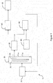
Figure 1 shows a schematic block diagram of an example of a switched-mode power supply in accordance with an aspect described herein; and -
Figure 2 shows schematically an example of variation of the gate voltage of a transistor of a synchronous rectifier with current flowing through the transistor of the synchronous rectifier. - As mentioned, a switched-mode power supply is an electronic power supply that incorporates a switching controller to convert electrical power efficiently. A switched-mode power supply may have a transformer for varying an input voltage to a different output voltage. The switching controller controls the voltage of an alternating current which is input to a primary winding of the transformer.
- In many applications, it is necessary to ensure that the output power from the transformer does not exceed some threshold and/or to ensure that the temperature of the transformer during operation does not exceed some threshold. In one standard safety test, the switched-mode power supply is operated so that the output power of the transformer is at a maximum and the temperature of the transformer is monitored. The temperature must remain below some threshold in order for the switched-mode power supply to pass the test. To ensure that the transformer passes the test, it is known to provide the switched-mode power supply with some protection such as maximum power protection, maximum current protection or maximum voltage protection, whereby the output power or current or voltage respectively is monitored and the switched-mode power supply is shut down if the maximum is exceeded. This is however a rather simple "brute force" way of protecting the transformer and/or switched-mode power supply as a whole.
- For many applications, a DC (direct current) output from the switched-mode power supply is required. Accordingly, the switched-mode power supply often has a rectifier which receives an AC (alternating current) which is output from a secondary winding of the transformer and converts it to DC. The DC output may be used to drive a device. The device may be one of many different types, including for example a component of a computer or other electronics device, including for example a television set, a DVD player, a set-top box, a display device (such as an LCD (liquid crystal display) screen, an OLED (organic light emitting diode) display screen, etc.), etc. The component may be for example a hard disk drive, one or more processors or integrated circuits, memory (e.g. RAM), a display device, an audio amplifier, etc.
- In addition, in many applications, plural DC outputs are required from the switched-mode power supply. This is common in applications where the switched-mode power supply is supplying a complex product, which has a number of components which require different operating voltages (such as 3.3V, 5V, 12V, etc.). This includes for example computers and other electronics devices mentioned above, which will typically have numerous electronic components that require different input operating voltages. A switched-mode power supply may therefore have a transformer that has plural secondary windings each connected to provide an output to a corresponding rectifier. In such a case, having a protection based on the maximum power, maximum current or maximum voltage output for the transformer as a whole may not be adequate and/or may not be most efficient. For example, such overall protection does not protect each of the multiple outputs separately.
- Where a switched-mode power supply is to provide one or more DC outputs and therefore has one or more rectifiers, synchronous rectification (also known as active rectification) may be used. In such a case, instead of using diodes, the or each rectifier uses one or more active switches to carry out the rectification from AC to DC. This can lead to much greater efficiency for the rectification and therefore the switched-mode power supply as a whole as it can significantly reduce power losses during the rectification. The active switch or switches may be for example transistors, including for example (power) MOSFETs (metal-oxide semiconductor field-effect transistors) and (power) bipolar transistors such as BJTs (bipolar junction transistors). As known, a MOSFET for example has a very low on-resistance RDS(on), meaning that the voltage drop across the MOSFET is low when conducting. The contrasts with the relatively high voltage drop across a diode, which leads to high power loss, which is undesirable of itself but also leads to (over)heating of the transformer. A controller provides a drive voltage to the gate of the or each MOSFET to control the switching of the MOSFET and therefore the rectification of AC to DC. The controller is usually synchronised with the input AC to ensure that the or each MOSFET is switched on and off at the correct times to achieve the desired rectification.
- Referring now to
Figure 1 , there is show a schematic block diagram of an example of a switched-mode power supply 10 in accordance with an aspect described herein. Thepower supply 10 has atransformer 20. Thetransformer 20 has aprimary winding 22 and at least onesecondary winding 24. In this example, thetransformer 20 has severalsecondary windings 24, indicated by thenumerals secondary winding 24, it being understood that the same or similar circuit arrangement may be provided for eachsecondary winding 24. Likewise, an example circuit arrangement for thesecondary windings 24 is only shown in full inFigure 1 for the firstsecondary winding 24. - The output of the
secondary winding 24 is passed to arectifier switching controller 30. Therectifier switching controller 30 may be provided in the form of for example an integrated circuit. Therectifier switching controller 30 provides an output to control asynchronous rectifier 40. Thesynchronous rectifier 40 rectifies the AC output by the secondary winding 24 to DC which is provided to anoutput 50 which, in turn in use is connected to a device or component that is to be powered by thepower supply 10. The output of thesynchronous rectifier 40 may be smoothed or filtered to provide a steady DC output. - The
synchronous rectifier 40 comprises one or more active switches that carry out the rectification under control of therectifier switching controller 30. The or each active switch may comprise a transistor. The transistors may be selected from for example (power) MOSFETs and (power) bipolar transistors such as BJTs. In a manner known per se, the output of therectifier switching controller 30 in this case is a drive voltage which drives the gate of the or each transistor to control the switching of the transistor and therefore the rectification of AC to DC. - Referring briefly to
Figure 2 , this shows schematically an example of variation of thegate voltage 100 of a transistor of thesynchronous rectifier 40 with current 200 flowing through the transistor of thesynchronous rectifier 40. The current that is flowing through the transistor of thesynchronous rectifier 40 is sensed by therectifier switching controller 30 which sets the gate voltage accordingly. As can be seen inFigure 2 , as thegate voltage 100 increases, the current 200 flowing through the transistor correspondingly increases, and as thegate voltage 100 decreases, the current 200 flowing through the transistor correspondingly decreases. - In accordance with the present disclosure, a
comparator 60 is provided to compare the output of therectifier switching controller 30, which is provided to the active switch of thesynchronous rectifier 40, with a reference. As mentioned, in this example, the active switch of thesynchronous rectifier 40 is a transistor and the output of therectifier switching controller 30 is a voltage that is applied to the gate of the transistor. Accordingly, in this example, the reference is in effect a maximum gate voltage that should be applied to the gate of the transistor of thesynchronous rectifier 40. That reference, in this case the maximum gate voltage that should be applied, may be determined previously by testing thepower supply 10 in use and finding the maximum that may be used whilst keeping the temperature of thepower supply 10, and more specifically thetransformer 20, below a desired or specified maximum. Thecomparator 60 is arranged such that if the output of therectifier switching controller 30 exceeds the reference, then thecomparator 60 outputs a corresponding control signal to atransformer switching controller 70. The control signal is such as to cause thetransformer switching controller 70 to operate such that the voltage of the alternating current which is input to the primary winding 22 of thetransformer 20 to be reduced, optionally to zero (i.e. in effect to switch off thetransformer 20 and therefore the power supply 10 a whole). This provides a simple and effective way of controlling the output of thepower supply 10. - In a switched-
mode power supply 10 which is for connection to an AC input power source, such as a mains electricity power supply, it is common for the input AC first to be rectified and filtered to provide a DC signal. That DC signal is then passed to a high frequency switch which inverts the DC signal to a high frequency AC signal. This process is principally to avoid an audible mains hum which can otherwise occur if for example a 50Hz mains electricity power supply is provided directly to the primary winding 22 of thetransformer 10. The high frequency AC signal may be at a frequency above 20kHz and may typically be from 50kHz to 200kHz or so and is therefore outside the normal range of human hearing. In such a case, thetransformer switching controller 70 controls the operation of the high frequency switch which is used to invert the DC signal to the high frequency AC signal to achieve the desired frequency and voltage level for the AC signal that is provided to the primary winding 22 of thetransformer 20. The high frequency switch may use one or more transistors, including for example MOSFETs and BJTs, which are controlled by thetransformer switching controller 70 in this example. - The
transformer switching controller 70 may be provided in the form of for example an integrated circuit (IC). In such case, transformer switchingcontroller IC 70 may have a protection pin which receives the control signal which is output by thecomparator 60 if the output of therectifier switching controller 30 exceeds the reference as discussed above. - The circuit arrangement discussed above for the first secondary winding 24, namely the
rectifier switching controller 30, thesynchronous rectifier 40 and itsoutput 50, thecomparator 60 and its reference, may be duplicated or repeated for one or more others of thesecondary windings 24 of thetransformer 20 in the case that thetransformer 20 has pluralsecondary windings 24 and corresponding outputs. In an example, the circuit arrangement discussed above is provided for each of the pluralsecondary windings 24. Importantly, this enables the voltage or power that is ultimately output to eachoutput 50 of the switched-mode power supply 10 to be monitored and controlled separately and independently. This is not possible with known switched-mode power supplies which only have "simple" protection such as maximum power protection, maximum current protection or maximum voltage protection. Moreover, importantly, this arrangement enables different references to be set for each output of the switched-mode power supply 10, which can reflect the different expected power and/or voltage requirements of that different outputs. - In the example shown, the reference to the
comparator 60 is provided by asquare wave generator 80. Thesquare wave generator 80 in this example is arranged to provide a square wave. The square wave is generated to have an amplitude that corresponds to the maximum gate voltage that is to be applied by therectifier switching controller 30 to the transistor(s) of thesynchronous rectifier 40 or, equivalently, an amplitude that corresponds to the maximum current that is to pass through the transistor(s) of thesynchronous rectifier 40 under control of therectifier switching controller 30. The frequency and/or duty cycle of the square wave is such as to correspond to the frequency and/or duty cycle of the output of therectifier switching controller 30 which is provide to control thesynchronous rectifier 40. This therefore provides a simple yet efficient arrangement for generating the reference for thecomparator 60. Moreover, the value of the reference is easily amended or adapted as necessary, for example during manufacture of the switched-mode power supply 10, by appropriate adjustment of thesquare wave generator 80. Finally, in the case that there are pluralsecondary windings 24 in thetransformer 20 and corresponding circuit arrangements which may be providing different output voltages, each circuit arrangement may have its ownsquare wave generator 80 which may therefore be used to set a reference for thecorresponding comparator 60 that is appropriate for the load that is being supplied by the correspondingoutput 50. - It will be understood that the processor or processing system or circuitry referred to herein may in practice be provided by a single chip or integrated circuit or plural chips or integrated circuits, optionally provided as a chipset, an application-specific integrated circuit (ASIC), field-programmable gate array (FPGA), digital signal processor (DSP), graphics processing units (GPUs), etc. The chip or chips may comprise circuitry (as well as possibly firmware) for embodying at least one or more of a data processor or processors and a digital signal processor or processors, which are configurable so as to operate in accordance with the exemplary embodiments. In this regard, the exemplary embodiments may be implemented at least in part by computer software stored in (non-transitory) memory and executable by the processor, or by hardware, or by a combination of tangibly stored software and hardware (and tangibly stored firmware).
- The examples described herein are to be understood as illustrative examples of embodiments of the invention. Further embodiments and examples are envisaged. Any feature described in relation to any one example or embodiment may be used alone or in combination with other features. In addition, any feature described in relation to any one example or embodiment may also be used in combination with one or more features of any other of the examples or embodiments, or any combination of any other of the examples or embodiments. Furthermore, equivalents and modifications not described herein may also be employed within the scope of the invention, which is defined in the claims.
Claims (12)
- A switched-mode power supply (10) comprising:a transformer (20), the transformer (20) comprising a primary winding (22) and at least one secondary winding (24);a transformer switching controller (70) arranged to control the voltage of an alternating current which is input to the primary winding (22) of the transformer (20);a synchronous rectifier (40) comprising an active switch for rectifying an alternating current which is output from the secondary winding (24) to a direct current which is to be output by the power supply (10);a rectifier switching controller (30) arranged to provide an output to control the active switch of the synchronous rectifier (40); anda comparator (60), the comparator (60) being arranged to compare the output of the rectifier switching controller (30) to the active switch of the synchronous rectifier (40) with a reference, the comparator (60) being arranged to output a control signal to the transformer switching controller (70) to cause the voltage of the alternating current which is input to the primary winding (22) of the transformer (20) to be reduced in the case that the output of the rectifier switching controller (30) exceeds the reference.
- A switched-mode power supply (10) according to claim 1, wherein the active switch of the synchronous rectifier (40) comprises at least one transistor and the output of the rectifier switching controller (30) is arranged to drive the gate of the transistor.
- A switched-mode power supply (10) according to claim 1 or claim 2, comprising a square wave generator (80) arranged to provide the reference in the form of a square wave.
- A switched-mode power supply (10) according to claim 3, wherein the square wave generator (80) is arranged to synchronise the output square wave with operation of the synchronous rectifier (40).
- A switched-mode power supply (10) according to any of claims 1 to 4, wherein:the transformer (20) comprises a plurality of secondary windings (24) each for providing a respective output alternating current;the switched-mode power supply (10) comprising:a corresponding plurality of synchronous rectifiers (40), each synchronous rectifier (40) being arranged to receive an output from a respective secondary winding (24), each synchronous rectifier (40) comprising an active switch for rectifying an alternating current which is output from the respective secondary winding (24) to a direct current which is to be output by the power supply (10);a corresponding plurality of rectifier switching controllers (30), each rectifier switching controller (30) being arranged to provide an output to control the active switch of the respective synchronous rectifier (40); anda corresponding plurality of comparators (60), each comparator (60) being arranged to compare the output of a respective rectifier switching controller (30) to the active switch of the synchronous rectifier (40) with a respective reference, the comparator (60) being arranged to output a control signal to the transformer switching controller (70) to cause the voltage of the alternating current which is input to the primary winding (22) of the transformer (20) to be reduced in the case that the output of the rectifier switching controller (30) exceeds the reference.
- A switched-mode power supply (10) according to claim 5, comprising a corresponding plurality of square wave generators (80) arranged to provide the references to the respective comparators (60).
- A method of operating a switched-mode power supply (10), the method comprising:controlling the voltage of an alternating current which is input to a primary winding (22) of a transformer (20) of the switched-mode power supply (10);controlling an active switch of a synchronous rectifier (40) with an output of a rectifier switching controller (30) to rectify an alternating current which is output from a secondary winding (24) to a direct current which is to be output by the power supply (10); andcomparing the output of the rectifier switching controller (30) to the active switch of the synchronous rectifier (40) with a reference, and outputting a control signal to cause the voltage of the alternating current which is input to the primary winding (22) of the transformer (20) to be reduced in the case that the output of the rectifier switching controller (30) exceeds the reference.
- A method according to claim 7, wherein the active switch of the synchronous rectifier (40) comprises at least one transistor and the output of the rectifier switching controller (30) drives the gate of the transistor.
- A method according to claim 7 or claim 8, comprising providing the reference in the form of a square wave.
- A method according to claim 9, wherein the square wave is synchronised with operation of the synchronous rectifier (40).
- A method according to any of claims 7 to 10, wherein:the transformer (20) comprises a plurality of secondary windings (24) each for providing a respective output alternating current; andthe switched-mode power supply (10) comprises:a corresponding plurality of synchronous rectifiers (40), each synchronous rectifier (40) receiving an output from a respective secondary winding (24), each synchronous rectifier (40) comprising an active switch for rectifying an alternating current which is output from the respective secondary winding (24) to a direct current which is to be output by the power supply (10);a corresponding plurality of rectifier switching controllers (30), each rectifier switching controller (30) providing an output to control the active switch of the respective synchronous rectifier (40); anda corresponding plurality of comparators (60), each comparator (60) comparing the output of a respective rectifier switching controller (30) to the active switch of the synchronous rectifier (40) with a respective reference, the comparator (60) outputting a control signal to cause the voltage of the alternating current which is input to the primary winding (22) of the transformer (20) to be reduced in the case that the output of the rectifier switching controller (30) exceeds the reference.
- A method according to claim 11, comprising providing each reference in the form of a square wave.
Priority Applications (2)
| Application Number | Priority Date | Filing Date | Title |
|---|---|---|---|
| EP17177120.7A EP3419152A1 (en) | 2017-06-21 | 2017-06-21 | Switched-mode power supply and method of operation |
| TR2017/09645A TR201709645A2 (en) | 2017-06-21 | 2017-06-30 | SWITCHING MODE POWER SUPPLY AND OPERATION METHOD |
Applications Claiming Priority (1)
| Application Number | Priority Date | Filing Date | Title |
|---|---|---|---|
| EP17177120.7A EP3419152A1 (en) | 2017-06-21 | 2017-06-21 | Switched-mode power supply and method of operation |
Publications (1)
| Publication Number | Publication Date |
|---|---|
| EP3419152A1 true EP3419152A1 (en) | 2018-12-26 |
Family
ID=59101337
Family Applications (1)
| Application Number | Title | Priority Date | Filing Date |
|---|---|---|---|
| EP17177120.7A Withdrawn EP3419152A1 (en) | 2017-06-21 | 2017-06-21 | Switched-mode power supply and method of operation |
Country Status (2)
| Country | Link |
|---|---|
| EP (1) | EP3419152A1 (en) |
| TR (1) | TR201709645A2 (en) |
Citations (3)
| Publication number | Priority date | Publication date | Assignee | Title |
|---|---|---|---|---|
| EP1199792A2 (en) * | 2000-10-20 | 2002-04-24 | SMK Corporation | Intermittent switching power supply circuit |
| US20070115700A1 (en) * | 2005-11-02 | 2007-05-24 | Nigel Springett | Transformer with current sensing means |
| US20140241018A1 (en) * | 2013-02-26 | 2014-08-28 | Champion Microelectronic Corporation | System and method for limiting output current in a switching power supply |
-
2017
- 2017-06-21 EP EP17177120.7A patent/EP3419152A1/en not_active Withdrawn
- 2017-06-30 TR TR2017/09645A patent/TR201709645A2/en unknown
Patent Citations (3)
| Publication number | Priority date | Publication date | Assignee | Title |
|---|---|---|---|---|
| EP1199792A2 (en) * | 2000-10-20 | 2002-04-24 | SMK Corporation | Intermittent switching power supply circuit |
| US20070115700A1 (en) * | 2005-11-02 | 2007-05-24 | Nigel Springett | Transformer with current sensing means |
| US20140241018A1 (en) * | 2013-02-26 | 2014-08-28 | Champion Microelectronic Corporation | System and method for limiting output current in a switching power supply |
Also Published As
| Publication number | Publication date |
|---|---|
| TR201709645A2 (en) | 2019-01-21 |
Similar Documents
| Publication | Publication Date | Title |
|---|---|---|
| CN108206634B (en) | Insulating synchronous rectification DC/DC converter, controller, adapter and equipment | |
| JP4975166B2 (en) | Multi-output synchronous flyback converter | |
| US9391525B2 (en) | Power system switch protection using output driver regulation | |
| US20160118900A1 (en) | Power supply adaptor | |
| US9991788B2 (en) | Power factor correction circuit for regulating operating frequency control circuit of power factor correction circuit and control method thereof, electronic apparatus, and power adapter | |
| US8300437B2 (en) | Multi-output DC-to-DC conversion apparatus with voltage-stabilizing function | |
| US20140192563A1 (en) | Dual-mode switching power control device | |
| CN104660024B (en) | Noise suppression method and voltage converter | |
| US10418906B2 (en) | High efficiency primary and secondary bias flyback converter with dual outputs | |
| US9973100B2 (en) | Synchronous rectifier applied to a power converter and operation method thereof | |
| US6809939B1 (en) | Synchronous rectifying control circuit of flyback switching power supply | |
| EP2953252B1 (en) | Systems and methods for controlling active rectifiers | |
| KR101227374B1 (en) | Motor circuit including an overcurrent detecting circuit for inverter and power supporting method of an overcurrent detecting circuit | |
| EP2690750B1 (en) | Uninterruptible power supply apparatus for receiving power from different electrical utility configurations | |
| JP2013516157A (en) | Device to disable synchronous rectifier | |
| US20180254696A1 (en) | Power Supply for Welding and Cutting Apparatus | |
| US20130100566A1 (en) | Power supply device | |
| US9391526B2 (en) | Power supply apparatus with auxiliary winding switching circuit | |
| US9564812B2 (en) | Power supply device and method for supplying power to the electronic device | |
| CN220754412U (en) | Uninterruptible power supply | |
| KR101145551B1 (en) | Synchronous rectifier | |
| CN109217674B (en) | Switching power supply device and switching control circuit | |
| KR20180073856A (en) | Switching driving circuit using urtit using isolated power source | |
| EP3422549A1 (en) | Switching power supply device and switching control circuit | |
| KR20170141393A (en) | Ac to dc converter and power supply device using the same |
Legal Events
| Date | Code | Title | Description |
|---|---|---|---|
| PUAI | Public reference made under article 153(3) epc to a published international application that has entered the european phase |
Free format text: ORIGINAL CODE: 0009012 |
|
| STAA | Information on the status of an ep patent application or granted ep patent |
Free format text: STATUS: THE APPLICATION HAS BEEN PUBLISHED |
|
| AK | Designated contracting states |
Kind code of ref document: A1 Designated state(s): AL AT BE BG CH CY CZ DE DK EE ES FI FR GB GR HR HU IE IS IT LI LT LU LV MC MK MT NL NO PL PT RO RS SE SI SK SM TR |
|
| AX | Request for extension of the european patent |
Extension state: BA ME |
|
| STAA | Information on the status of an ep patent application or granted ep patent |
Free format text: STATUS: REQUEST FOR EXAMINATION WAS MADE |
|
| 17P | Request for examination filed |
Effective date: 20190624 |
|
| RBV | Designated contracting states (corrected) |
Designated state(s): AL AT BE BG CH CY CZ DE DK EE ES FI FR GB GR HR HU IE IS IT LI LT LU LV MC MK MT NL NO PL PT RO RS SE SI SK SM TR |
|
| STAA | Information on the status of an ep patent application or granted ep patent |
Free format text: STATUS: EXAMINATION IS IN PROGRESS |
|
| 17Q | First examination report despatched |
Effective date: 20190822 |
|
| STAA | Information on the status of an ep patent application or granted ep patent |
Free format text: STATUS: THE APPLICATION HAS BEEN WITHDRAWN |
|
| 18W | Application withdrawn |
Effective date: 20200227 |